

Page 1
Operating
M
0
-
r
C
o
3
anual
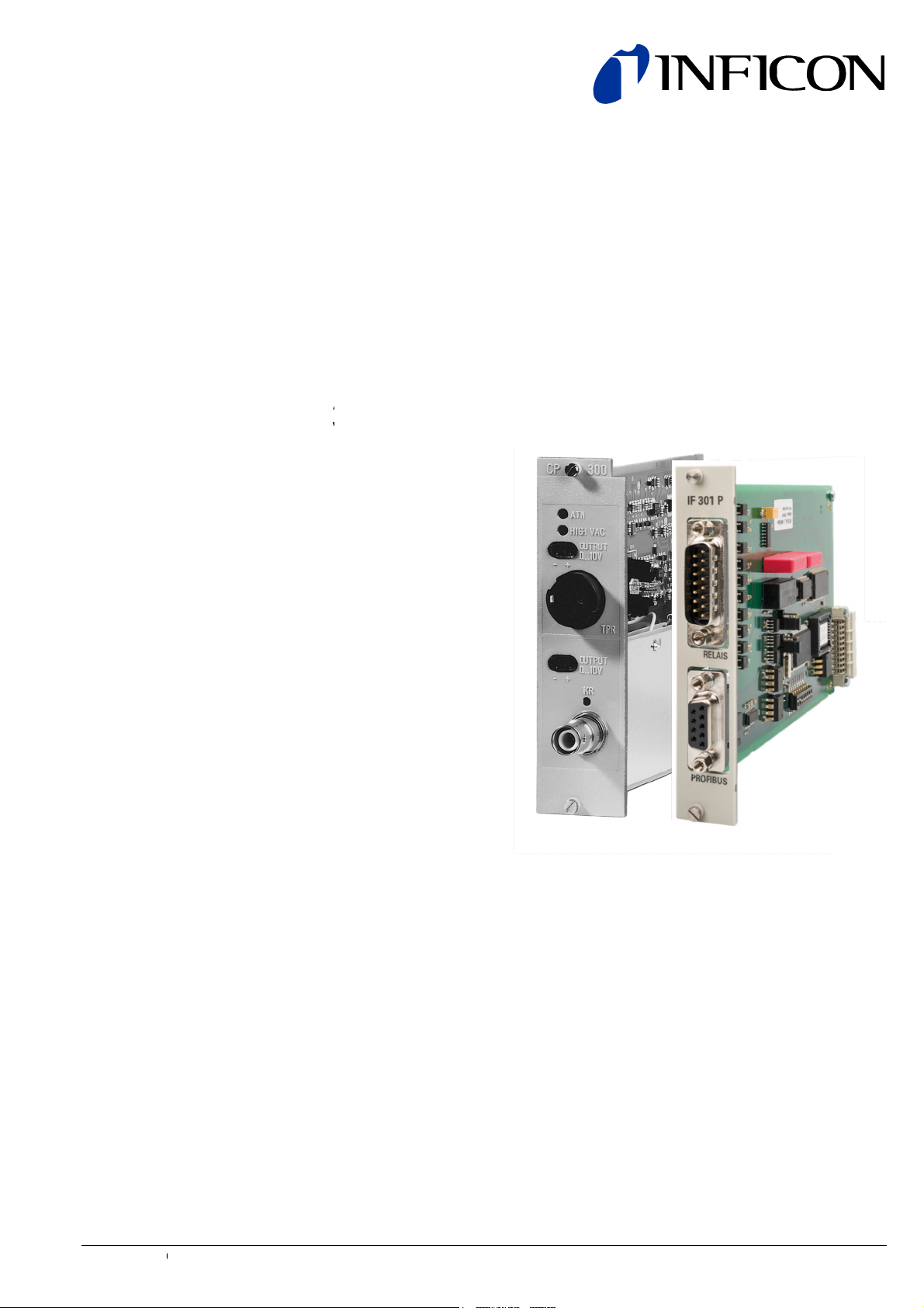
Plug
Cont
CP300
IF300P
In B
oller
9,
ards
TPG
for T
00
otal Pressure Gauge
IG9972BEN (2
017-09)
1
Page 2
About this Document
Validity
This document describes the plug-in boards for the total pressure gauge controller TPG300, intended as a supplement to the documentation of the basic unit
TPG300 (→ [1]).
This document applies to plug-in boards listed below
Type Description Part number
CP300C9 Pirani / cold cathode measurement board IO441000
IF300P Interface and relay Board (Profibus) IO441395
The part number (No) can be taken from the product nameplate.
2 IG9972BEN (2017-09) Plug-In Boards.om
Page 3

Contents
About this Document 2
Validity 2
1 Safety 4
1.1 General Safety Information 4
1.2 Symbols Used 4
1.3 General Stipulations 4
2 Description 5
2.1 Pirani / Cold Cathode Measurement Board CP300C9 5
2.2 Interface and Relay Board IF300P 5
2.3 Pirani Measurement 5
2.4 Cold Cathode Measurement 5
3 Technical Data 6
3.1 Pirani / Cold Cathode Measurement Board CP300C9 6
3.2 Interface and Relay Board IF300P 7
4 Installation 8
4.1 Installing / Removing the Plug-In Boards 8
4.2 Connecting the Pirani Gauge 8
4.3 Connecting the Cold Cathode Gauge 9
4.4 Connecting the <OUTPUT> Analog Signal 10
4.5 Connecting the Relays of the IF300P 10
4.6 Connecting the Profibus-DP Interface to the IF300P 11
5 Adjustment 12
5.1 Adjusting the Pirani Measurement Circuit 12
6 Troubleshooting 13
6.1 Operating and Adjustment Problems 13
6.2 Defects 13
6.3 Problems with the RS232C Interface 13
6.4 Problems with the Profibus-DP Interface 14
7 Accessories 15
7.1 Gauges 15
7.2 Measurement Cables and Cable Connectors 15
Appendix 17
A: Output Signals of the Measurement Boards 17
B: Gas Type Dependence 19
C: Literature 21
IG9972BEN (2017-09) Plug-In Boards.om 3
Page 4
1 Safety
1.1 General Safety
Information
1.2 Symbols Used
a) Take the necessary precautions when doing installation work.
It may be necessary implement additional protective measures in the system.
b) Before connecting any external elements, check that they are compatible with
the technical data in this document.
c) Take the necessary precautions when doing maintenance or repair work.
Danger:
Information on preventing any kind of personal injury or extensive
equipment damage.
Caution:
Special information on damage prevention.
Note:
Special information on cost-effective use.
1.3 General Stipulations
Skilled Personnel:
This work may only be carried out by persons with suitable technical
training and the necessary experience.
Waiting time, reaction time, duration of test
<
… > Marking
→ See page …
→ See document …
Since the individual components are delicate, appropriate measures must be taken
to protect them from static electricity. Store modules in antistatic bags or containers.
Damage resulting from incorrect handling may lead to a revocation of the
guarantee.
INFICON accepts no responsibility nor warranty if the user or third parties
• utilize the product not according to the defined use
• make any kind of changes (modifications, alterations, etc.) to the product.
4 IG9972BEN (2017-09) Plug-In Boards.om
Page 5

2 Description
2.1 Pirani / Cold Cathode
Measurement Board
CP300C9
Pirani measurement circuit
Cold cathode measurement
circuit
2.2 Interface and Relay
Board IF300P
2.3 Pirani Measurement
2.4 Cold Cathode
Measurement
The CP300C9 board is a combined board containing one Pirani and one cold
cathode measurement circuit.
The Pirani measurement circuit has one gauge cable connector, two trimmer potentiometers and one analog signal output. When the control unit is on, the Pirani
measurement circuit is in continuous operation. The analog signal is constantly
available, independent of what is shown on the pressure display.
The cold cathode measurement circuit for the measurement of high and ultra high
vacuum has one gauge cable connector and one analog signal output. When the
gauge is turned on, the analog signals are constantly available, independent of
what is shown on the pressure display.
This measurement board contains special electronics to limit the measurement
current to 100 µA, a feature that considerably extends the lifetime of the gauge.
The IF300P board contains a RS232C interface and a Profibus-DP interface. The
board has five relays with one floating changeover contact each.
Within certain limits the thermal conductivity of gases is a function of the pressure.
Pirani thermal conductivity vacuum gauges exploit this phenomenon for pressure
measurements.
The measurement element consists of a thin filament with a high temperature coefficient. The resistance of the wire and consequently its temperature are maintained at a constant value by means of a suitable control circuit. The electrical
power supplied to the filament is, therefore, a measure of the thermal conductivity
and consequently the gas pressure.
The current flowing in a self-sustained gas discharge with a cold cathode (inverted
magnetron) depends on the applied voltage, the gas composition, and the pressure. A magnetic field that penetrates the measurement chamber has the effect
that the electrons move along a spiral trajectory from the cathode to the anode and
thereby cause even at low gas densities a sufficient number of ionizing impacts for
maintaining the discharge. If (with a known gas type) the anode voltage and magnetic field are kept constant, the discharge current is a measure of the pressure.
IG9972BEN (2017-09) Plug-In Boards.om 5
Page 6

3 Technical Data
3.1 Pirani / Cold Cathode
Measurement Board
CP300C9
Number of measurement circuits 1 each
Gauges TPR018, IKR085 (both ITER)
Display range (signal output) 1)
Pirani
Cold cathode
mbar
mbar
5×10⁻⁴ … 1000
-9
… 1×10⁻²
5×10
Measurement range 1)
Pirani
Cold cathode
mbar
mbar
1×10⁻² … 100
-8
… 5×10⁻³
1×10
Cable length
Pirani, max.
Cold cathode, max.
m
m
100
60
2)
… 100
Power supply cold cathode gauges
Operating voltage
Measurement current
kV
µA
3.3
≤600
Signal output
Measured value, analog
Error message
Current, max.
Output resistance
Reaction time (10 90%) for sudden
V
V
mA
Ω
0 … +10
>11.5
2
400
pressure step
Pirani
-3
<10
103 mbar
Cold cathode
-9
⇔ 10-6 mbar
10
ms
ms
<50
<100
Connection, equipment side
Pirani gauge
Cold cathode gauge
Signal output
Weight kg
female
female
female
Amphenol C91E, 6-pin
SHV coaxial
ø2 mm
≈0.21
1)
N2-equivalent
2)
when using the lower measurement range limit (→ 9)
6 IG9972BEN (2017-09) Plug-In Boards.om
Page 7
3.2 Interface and Relay
Board IF300P
Relay
Number 5
Contact type 1 change over contact each
floating
max. 50 V (ac) relative to other
contacts and ground
Characteristic data (ac)
Switching voltage, max.
Switching current, max.
Switching power, max.
30 V (dc), 50 V (ac)
1.5 A
45 W, 75 VA
Characteristic data (dc)
Switching current, max. switching voltages >50 V (dc) are
inadmissible for safety reasons
0.6 A at 50 V (dc)
0.8 A at 40 V (dc)
1.5 A at 30 V (dc)
Connection, equipment side
Type D-sub connector, 15-pin, male
Transition resistance with socket
125 mΩ
Interface
Type Profibus-DP
Baud rates <12Mbaud
Data format
Profibus-DP interface → [2]
Connection, equipment side D-sub connector, 9 pin, male
Cable length, max.
Weight
→ [2]
≈0.16 kg
Before connecting any external elements, check that they conform to the
above technical data and the controller is switched off for at least
15 seconds.
IG9972BEN (2017-09) Plug-In Boards.om 7
Page 8

4 Installation
General
4.1 Installing / Removing
the Plug-In Boards
Use screened cables only (connect screen to barrel of connector). If both
ends of the screen are connected to ground, compensating currents must
be prevented (e.g. by connecting all involved units to a common power
distributor).
In a Profibus-DP installation (IF300P board), use the recommended special
cable only (→ [2]).
For safety reasons, vacant slots should always be covered with blank
panels.
Disconnect all cables from the unit before installing / removing any plugin modules.
Procedure
4.2 Connecting the Pirani
Gauge
Modules should only be handled on an ESD protected bench.
• Switch off the unit and wait one minute
• Remove all cables (power cable last)
• Unscrew the blind plate / plug-in module
• Insert / remove plug-in module
• Screw on the plug-in module / blind plate
• Connect the cables (mains cable first)
• Switch on the unit again
To ensure correct operation, check that the screws of the plug-in
modules are tightened.
Additional protective measures must be taken if certain processes in the
vacuum system (e.g. flashovers) can cause hazardous voltages on the
gauge terminals.
Although the gauge cables are screened, they should not be routed in
parallel to lines producing strong electrical noise.
Connect the gauge to the <TPR> connector on the rear panel. The connectors are
locked so that they cannot be separated accidentally.
8 IG9972BEN (2017-09) Plug-In Boards.om
Page 9

4.3 Connecting the Cold
Cathode Gauge
Additional protective measures must be taken if certain processes in the
vacuum system (e.g. flashovers) can cause hazardous voltages on the
gauge terminals.
Although the gauge cables are screened, they should not be routed in
parallel to lines producing strong electrical noise.
Connect the gauge to the <IKR> connector. Coaxial cables normally suffice. The
following diagram indicates the conditions under which a triaxial cable is required.
The maximum length of 100 m for coaxial cables is specified by
EN 61010. Greater lengths are not admissible without additional protective measures.
If the gauge is not grounded via the vacuum chamber, it must be
grounded separately.
If the cable length is >100 m (only admissible with triaxial cable), the
connectors must be protected against unintentional separation and
contact of the center conductor. The cable must only be plugged in or
detached while the unit is switched off for at least 15 seconds.
IG9972BEN (2017-09) Plug-In Boards.om 9
Page 10

4.4 Connecting the
<OUTPUT>
Analog Signal
4.5 Connecting the Relays
of the IF300P
Pin Assignment
Protection against unintentional separation of the triaxial connector.
Each measurement circuit is equipped with an analog
signal output. Matching connectors are included with
each measurement board.
The relay connector on the rear of the IF300P has the following pin assignment:
15
Relay 1
8
(Switching function 1)
7
14
Relay 2
6
(Switching function 2)
13
5
Relay 3
12
(Switching function 3)
4
11
Relay 4
3
(Switching function 4)
10
2
Relay 5
1
(Error status)
9
15
9
IF 300P
1
8
Screen
Contacts shown de-energized
Pin location
10 IG9972BEN (2017-09) Plug-In Boards.om
Page 11

4.6 Connecting the
Profibus-DP Interface to
the IF300P
Pin Assignment
In a Profibus-DP installation, use the recommended special cable only
(→ [2]).
The interface connector on the rear of the IF300P has the following pin assignment:
Pin
1
Screen
2
3
4
5
6
Do not connect
RxD/TxD-P (B wire)
CNTR-P (optional)
DGND
VP (Only necessary
IF 300P
a bus end devices)
7
8
9
Do not connect
RxD/TxD-N (A wire)
Do not connect
9
6
5
1
IG9972BEN (2017-09) Plug-In Boards.om 11
Page 12

5 Adjustment
5.1 Adjusting the Pirani
Measurement Circuit
Pirani measurement circuits are factory-adjusted to the standard gauge. Due to
manufacturing tolerances, contamination of the gauges, and different cable
lengths, deviations are inevitable.
Cold cathode measurement circuits are factory-adjusted and require no readjustment.
Two trimmer potentiometers are available for compensating the gauge tolerances, gauge contamination, or
different cable lengths, within certain limits.
Adjustment at High Vacuum
Adjustment at Atmospheric
Pressure
The adjustment should only be performed
after the equipment has attained operating
temperature (≈10 minutes).
• With gauge connected, lower the vacuum chamber pressure to <1×10⁻⁴ hPa
• Select the measurement circuit to be adjusted (»sensor« mode)
-4
• With the <HIGH VAC> potentiometer adjust the display to 8.0×10
hPa
• Turn the potentiometer clockwise by 90°
• «ur 10-4» should now be displayed (→ [1]).
• Expose the gauge to atmospheric pressure (vent the vacuum chamber)
• Turn the <ATM> potentiometer to obtain a reading of 1.0×10³ hPa
• Decrease the pressure to <1×10⁻⁴ hPa
• Check the high vacuum reading and readjust, if necessary.
12 IG9972BEN (2017-09) Plug-In Boards.om
Page 13

6 Troubleshooting
6.1 Operating and
Adjustment Problems
6.2 Defects
6.3 Problems with the
RS232C Interface
In addition to the guidelines below, take the documentation of the other system
components into account (→ Literature 21).
Problem Possible cause Correction
Pirani reading too high Pirani gauge contami-
nated
Adjust Pirani measurement circuit (→ 12)
Clean gauge (→ [3])
Replace gauge
Cold cathode reading
too high
Air humidity
Connector insulation
contaminated or moist
Clean insulation or replace connector
Keep the air humidity low
( leakage current)
Keep the equipment in
constant operation
Cold cathode reading
too low
Cold cathode gauge
contaminated
Clean gauge
(→ [4])
Replace ionization
chamber
Pirani can not be
adjusted
Incorrect combination
measurement board –
Select correct
combination (→ 8)
gauge – cable
Gauge severely contami-
nated
Clean or replace gauge
(→ [3])
Problem Possible cause Correction
Cold cathode constantly
indicates « »
Short circuit in the cold
cathode cable / gauge
Replace or repair the
cable / gauge
(overrange), (even
though
the pressure is within the
measuring range)
Cold cathode measurement board defective
Replace the cold cathode
measurement
board(→ 8)
Cold cathode indicates
No IKR gauge connected Connect the gauge
« » (underrange),
even though the pressure
is within the measuring
range
Cold cathode gauge
Cold cathode measure-
Interruption in cold
cathode cable
defective
ment board defective
Replace or repair the
cable
Replace the gauge
(→ [4])
Replace the cold cathode
measurement board
(→ 8)
Problem Possible cause Correction
No communication Pin 2 and 3 of the inter-
Use the correct cable
face cable not crossed
Incorrect Baud rate Match Baud rate
Incorrect data format Adhere to the format
specified for the TPG300
(→ [1])
IG9972BEN (2017-09) Plug-In Boards.om 13
Page 14

6.4 Problems with the
Profibus-DP Interface
Problem Possible cause Correction
No communication Incorrect Baud rate 1) Set Baud rate to
19200 Baud
Incorrect data format Adhere to the standardized
Profibus-DP data format
(→ [2])
Cycle time >100 ms Incorrect firmware Firmware TPG300:
302-654
Firmware Profibus: V1.5
Incorrect Baud rate
1)
Set Baud rate to
19200 Baud
1)
At the controller TPG300, firmware 302-654 or higher
14 IG9972BEN (2017-09) Plug-In Boards.om
Page 15

7 Accessories
A
7.1 Gauges
7.2 Measurement Cables
and Cable Connectors
Pirani Measurement cables
Pirani cable connectors
controller side
Pirani cable connectors
gauge head side
Gauge Compatible to
Vacuum connection Ordering number
measurement board:
TPR018
→ [3]
IKR085
→ [4]
CP300C9 DN 16 ISO-KF
DN 40 CF-F
CP300C9 DN 40 ISO-KF
DN 40 CF-F
IO G15 020
IO G15 024
PT R18 772
PT R18 773
With Amphenol C91 and Lemo (standard plugs on each side).
Length [m] 80 °C
Pirani Measurement
cables for TPR018
Measurement cables, high
temperature version for TPR0181)
250 °C
3 ITC548308 ITC548414
5 – ITC548465
10 ITC548456 ITC448047
15 ITC548457 ITC448043
20 ITC548458 ITC448044
25 ITC548459 ITC120025
30 ITC548460 ITC120030
35 ITC548461 ITC120035
40 ITC548462 ITC120040
45 ITC548463 ITC120045
50 ITC548464 ITC120050
1)
Pirani measurement cable for TPR018:
4
2
1
5
LEMO
female
mphenol C91E
male
4
2
1
5
3
Connectors controller side Ordering Number
Amphenol C91 IT4722125
Crimp contact C91 plug connector IT4722841
Connectors gauge head side Ordering Number
Lemo 4.3 – 5.2 mm IT4722062
Lemo 5.3 – 6.2 mm IT4722063
IG9972BEN (2017-09) Plug-In Boards.om 15
Page 16

Cold Cathode Measurment
Cables
Cold cathode cable
connectors controller side
Cold cathode cable
connectors gauge head side
With SHV and Triax Lemo (standard plugs on each side).
(Test voltage: 6 kV (dc))
Length
[m]
80 °C
Pirani Measurement
cables for IKR085
250 °C
Measurement cables, high
temperature version for IKR0851)
3 ITC220003 ITC230003
5 ITC220005 ITC230005
10 ITC220010 ITC230010
15 ITC220015 ITC230015
20 ITC220020 ITC230020
25 ITC220025 ITC230025
30 ITC220030 ITC230030
35 ITC220035 ITC230035
40 ITC220040 ITC230040
45 ITC220045 ITC230045
50 ITC220050 ITC230050
Connectors controller side Ordering Number
SHV-50-Peek IT4726605
SHV-50-Capton IT4728606
Connectors gauge head side Ordering Number
Triax IT1001030
Coax IT100103116
16 IG9972BEN (2017-09) Plug-In Boards.om
Page 17

Appendix
A: Output Signals of the
Measurement Boards
Pirani Gauge
TPR018 with CP300C9
IG9972BEN (2017-09) Plug-In Boards.om 17
Page 18

Cold Cathode Gauge
IKR085 with CP300C9
18 IG9972BEN (2017-09) Plug-In Boards.om
Page 19

B: Gas Type Dependence
Pirani Gauge TPR018
Indicated pressure (instrument calibrated for air)
IG9972BEN (2017-09) Plug-In Boards.om 19
Page 20

Cold Cathode Gauge IKR085
Indicated pressure (Instrument calibrated for air)
(Mean values, deviations possible depending on degree of contamination).
Reference gauge: Hot cathode ionization gauge
20 IG9972BEN (2017-09) Plug-In Boards.om
Page 21

C: Literature
[1] www.inficon.com
Operating Manual
Total Pressure Gauge Controller TPG300
IG9970BEN
INFICON AG, LI–9496 Balzers, Liechtenstein
[2] www.inficon.com
Communication Protocol
Profibus-DP Interface Board IF300P
IG9973BEN
INFICON AG, LI–9496 Balzers, Liechtenstein
[3] www.inficon.com
Operating Manual
Pirani Gauge TPR018
BG9976BEN
INFICON AG, LI–9496 Balzers, Liechtenstein
[4] www.inficon.com
Operating Manual
Cold Cathode Gauge IKR085
IG9048BEN
INFICON AG, LI–9496 Balzers, Liechtenstein
IG9972BEN (2017-09) Plug-In Boards.om 21
Page 22

LI–9496 Balzers
Liechtenstein
Tel +423 / 388 3111
Fax +423 / 388 3700
Original: English reachus@inficon.com
i g9972ben
www.inficon.com
 Loading...