

Page 1
TECHNICAL HANDBOOK
kina40e1-g (1007)
Catalog No.
510-010
510-015
510-016
510-017
510-018
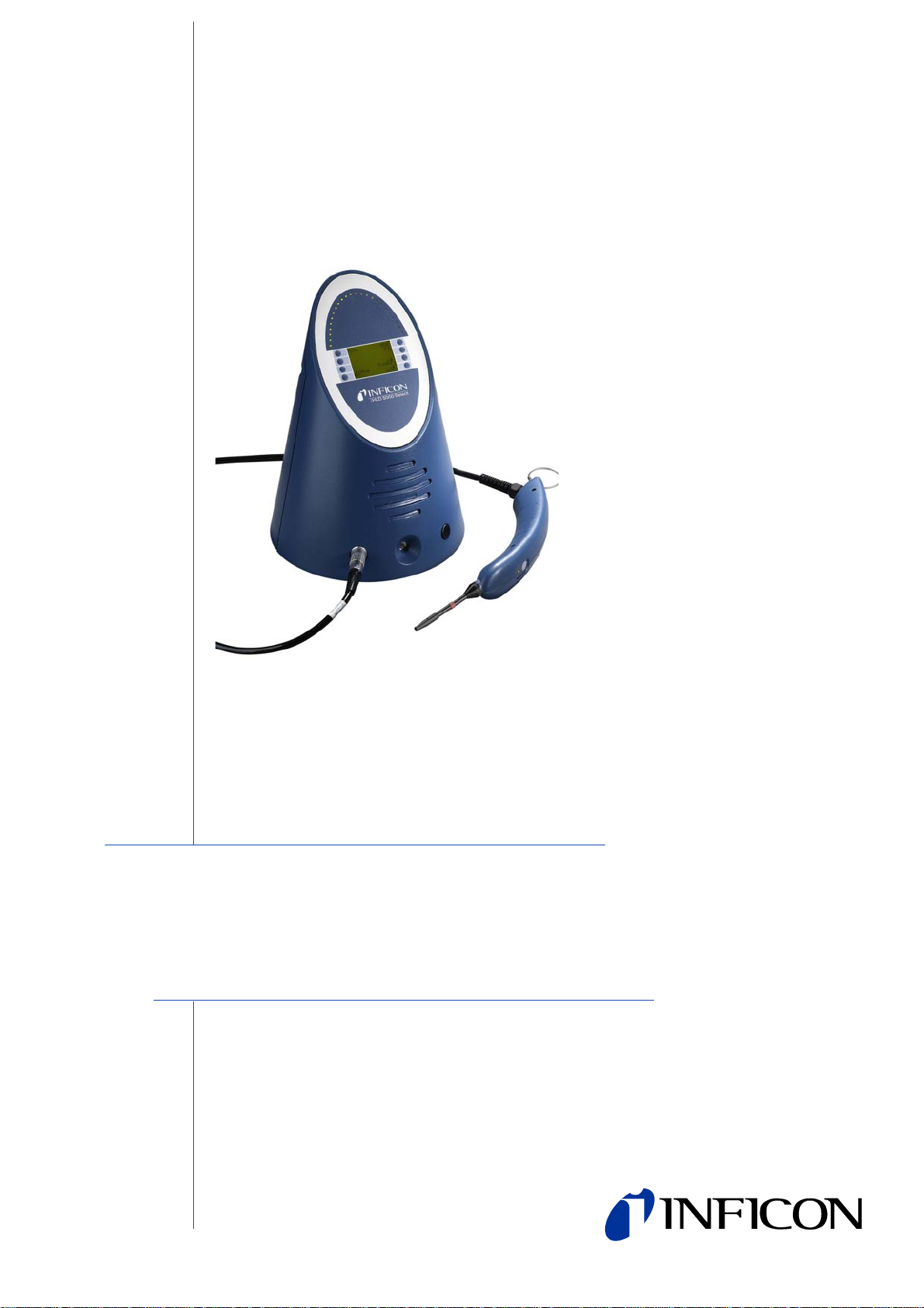
HLD5000
Refrigerant Sniffer Leak Detector
from software version V 4.1
Page 2

0-2
kina40e IVZ.fm technical handbook(1007)
Page 3
Content
1 General 1-1
1.1 Introduction 1-1
1.1.1 Purpose 1-1
1.2 Technical Data 1-2
1.2.1 Physical Data 1-2
1.2.2 Electrical Data 1-2
1.2.3 Other Data 1-2
1.2.4 Ordering Information 1-3
1.3 Supplied Equipment 1-3
1.3.1 Replacement parts / Accessories 1-4
1.4 Service 1-5
1.4.1 Service Centers 1-6
1.5 Notes on How to Read this Manual 1-8
1.5.1 Definition of Terms 1-8
1.6 Installation 1-9
1.6.1 Unpacking 1-9
1.6.2 Mechanical Connections 1-9
1.6.3 Electrical Connection 1-9
1.6.4 Wall Mounting 1-9
1.6.5 RS232 Interface 1-10
1.6.6 The Sniffer Tip 1-10
1.6.6.1 Changing the sniffer tip 1-10
1.6.6.2 Use of the flexible sniffer tip 1-11
1.6.6.3 Use of the sniffer tip extension 1-11
1.6.6.4 Use of water protection tip 1-11
2 Principle of Operation 2-1
2.1 Description 2-1
2.2 HLD5000 Overview 2-2
3 Operating the HLD5000 3-1
3.1 Start-up 3-1
3.2 Working with the HLD5000 3-2
3.3 Controls and their Function 3-3
3.3.1 Overview of the Controls and Display Components 3-3
3.3.2 Mains Switch 3-3
3.3.3 LED Display of the HLD5000 3-3
3.3.4 LC Display 3-3
3.3.5 Probe 3-5
4 HLD5000 Settings (Menu Structure) 4-1
4.1 Description of the Menu "Program” 4-1
4.1.1 TRIGGER 4-2
4.1.2 VOLUME 4-3
kina40e IVZ.fm technical handbook(1007)
4.1.3 CONTRAST 4-3
Content 0-3
Page 4

4.1.4 OPTIONS 4-4
4.1.5 CAL 4-6
4.1.6 LIST ERRORS 4-6
4.1.7 INFO 4-6
4.2 Description of the Menu Item INFO 4-8
4.3 Menu Item STANDBY 4-9
4.4 Selecting the gas type 4-9
4.5 Calibration 4-9
4.5.1 Checking the Calibration 4-10
4.5.2 Calibrating the HLD5000
with the COOL-Check 4-10
4.5.3 Calibrated leak (COOL-Check) 4-11
4.6 Shutting Down 4-11
4.7 Switching probes 4-11
5 Messages 5-1
6 Maintenance 6-1
6.1 INFICON Service 6-1
6.2 Maintenance Work 6-1
6.2.1 Replacing the Filters 6-1
6.2.1.1 Exchanging the filters in the sniffer line 6-1
6.2.2 Cleaning the Opening of the Calibrated Leak 6-3
6.2.3 Cleaning 6-3
6.2.4 Replacing Fuses 6-3
6.2.5 Replacing the Calibrated Leak
(not for SF6 / CO2 version) 6-3
Appendix A-1
kina40e IVZ.fm technical handbook(1007)
0-4 Content
Page 5
General Safety Precautions
Warning
Caution
Warning
Warning
Warning
Indicates procedures that must be strictly observed to prevent hazards to persons.
Indicates procedures that must strictly be observed to prevent damage to or
destruction of the HLD5000 leak detector.
Notice Indicates special technical requirements that the user must comply with.
The INFICON HLD5000 leak detector has been designed for safe and efficient
operation when used properly and in accord ance with this Te chnical Handbo ok. It is
the responsibility of the user to carefully read and strictly observe all safety
precautions described in this chapter and throughout this Technical Handbook. The
HLD5000 must only be operated in the proper condition and under the conditions
described in this Technical Handbook. It must be operated and maintained by trained
personal only. Consult local, state, and national agencies regarding specific
requirements and regulations. Adress any further safety, operation and / or
maintenance questions to our nearest office.
Failure to observe the following precautions could result in serious personal
injury:
The HLD5000 must not be operated while standing in water or under running or
dripping water. The same applies to all other kinds of liquids.
The HLD5000 should only be used indoors.
The HLD5000 must not be operated in explosion hazard areas.
Do not use the HLD5000 on hot surfaces.
Only mains cords having three conductors with a protective ground conductor may
be used. The HLD5000 must never be operated with a disconnected protective
kina40e IVZ.fm technical handbook(1007)
ground conductor.
General Safety Precautions 0-5
Page 6
Warning
Danger of electric shock.
Warning
Caution
Caution
Caution
Caution
Caution
• Don’t touch live parts with the sniffer tip.
• Test samples need to be disconnected from electricity before leak testing.
To replace the fuses remove the mains cord first.
Failure to observe the following precautions could result in damage to the
equipment:
Avoid contact of the HLD5000 with bases, acids or solvents and also avoid
exposure to extreme climatic conditions.
Before loosening the connecting nut, you must switch off the HLD5000 first. When
exchanging the sniffer tip make sure th at no dust or particles of dirt enter into the
opening.
The HLD5000 will only operate after having connected the sniffer line first.
Do not place the HLD5000 on hot surfaces.
During warm-up the sniffer tip must not be inserted in the test leak opening.
Otherwise, the internal calibration will be disabled and an error message will be
displayed.
0-6 General Safety Precautions
kina40e IVZ.fm technical handbook(1007)
Page 7

Caution
Under all circumstances the intake of liquids which may still be present on the
Caution
Caution
Caution
surface of the test object has to be avoided.
In the case of moist test objects (e.g. condensed water) the use of the water
protection tip is recommended (see Chapter 1.6.6).
Under all circumstances memorize the new PIN!
The PIN can only be reset by INFICON’s service organization.
Before exchanging any of the sniffer line filters please switch off the HLD5000.
When replacing filters please make sure that no particles enter into the intake
opening.
Before replacing the air filter at the bottom of the housing please disconnect the
HLD5000.
kina40e IVZ.fm technical handbook(1007)
General Safety Precautions 0-7
Page 8

0-8 General Safety Precautions
kina40e IVZ.fm technical handbook(1007)
Page 9
1 General
Warning
Caution
Warning
The refrigerant leak detector HLD5000 is delivered ready for use. Even so, we
strongly recommend that you carefully read this manual so as to ensure optimum
operating conditions right from the start.
1.1 Introduction
1.1.1 Purpose
The HLD5000 is suited for running sniffer leak tests on air conditioning and
automotive air-conditioning systems (overpressure method). Its area of application is
within the air-conditioning industry and it is used to check air-conditioners as well as
components these contain.
The HLD5000 must not be operated while standing in water or under running or
dripping water. The same applies to all other kinds of liquids.
The HLD5000 should only be used indoors.
Avoid contact of the HLD5000 with bases, acids or solvents and also avoid
exposure to extreme climatic conditions.
The HLD5000 must not be operated in explosion hazard areas.
Do not use the HLD5000 on hot surfaces.
Applied guide lines, harmonized standards and applied national standards in
languages and specifications:
EN 50081-1 electromagnetical compatibility
EN 61000-6-2 electromagnetical compatibility
EN 61010-1 electrical safety
kina40e 01.fm technical handbook(1007)
General 1-1
Page 10
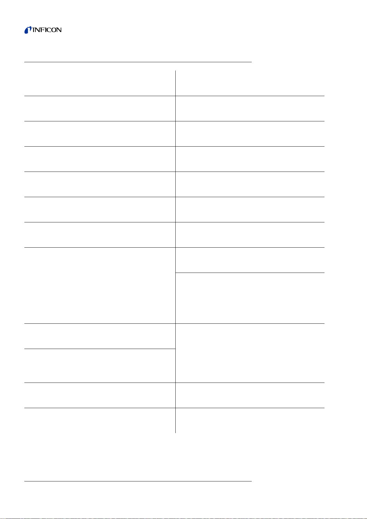
1.2 Technical Data
1.2.1 Physical Data
Lowest trigger level setting
Maximum trigger level setting 50 g/a (1.76 oz/yr)
Measurement range
Detectable refrigerants
Response time 1 s
Time until ready for operation 30 s
Recovery time approx. 2 s
Gross leak recovery time approx. 8 s
For single gas probes 1.0 g/a (0.04 oz/yr)
For universal Smart probe 0.5 g/a (0.02 oz/yr)
For single gas probes 0 - 100 g/a (3.57 oz/yr)
For universal Smart probe 0 - 300 g/a (10.7 oz/yr)
Single gas probe
(depending on the instrument version)
Universal Smart probe all halogens
R134a,
R744 (CO
), SF
2
6
1.2.2 Electrical Data
Mains supply voltage 100 V ... 230 V ± 10 %
Power consumption
in standby
Protection IP 30
Overvoltage category II
Gas flow at the intake 320 sccm
1.2.3 Other Data
Dimensions (height, diameter) 365 mm; 260 mm
Weight of the main unit 4.5 kg (10 lb.)
Weight of the probe 390 g (0.9 lb.)
Permissible ambient temperatur e ra ng e
(during operation)
Max. rel. humidity of the air 80 % at +31 °C, decreasing
Length of the sniffer line 4.8 m (15.5 ft.)
50/60 Hz
< 60 VA
< 40 VA
(14.4 in.; 10.25 in.)
5 – 50 °C; 40 – 120 °F
to 50% at 40°C (104°F)
1-2 General
kina40e 01.fm technical handbook(1007)
Page 11

Visual leak rate indication LED display, 24 pcs.;
Noise level <50 dBA
Pollution degree 2
Audio alarm 100 dBA
Max. permissible height above sea level
(during operation)
1.2.4 Ordering Information
HLD5000 for R134a Cat. No. 510-010
HLD5000 for R744 (CO
HLD5000 for SF
HLD5000 with Smart Probe Cat. No. 510-017
HLD5000 for R600a/R290 Cat. No. 510-018
1.3 Supplied Equipment
0 – 200 %;
(trigger level = 100 %)
2000 m
) Cat. No. 510-015
2
6
Cat. No. 510-016
The HLD5000 is delivered ready for operation. Before installing the HLD5000 please
read Chapter 1.6. The following items have been included with the leak detector:
• Probe with line
• Sniffer tip, 100 mm long
• Flexible extension for sniffer tip with adapter
• 2 mains cords EU version, US version
• Documentation
– Operating Instructions of the HLD5000 kima40e2
– Technical Handbook HLD5000 kina40e1
– Interface Description HLD5000 kins40e1
– Spare Parts List HLD5000 kiua40e1
– Repair Instructions kipa40e1
– HEX Code
• Set of spare fuses
• Set of replacement filter holders (5 pieces)
• Set of replacement silicone filter cartridges (4 pieces)
For R744 (CO
• Adapter for CO
) version (510-015) only:
2
calibration
2
kina40e 01.fm technical handbook(1007)
General 1-3
Page 12

1.3.1 Replacement parts / Accessories
Sniffer tips
Probe tip, 100 mm long 511-021
Probe tip, 400 mm long, flexible 511-024
Extension line, 400 mm long (flexible) for the
probe tip (20 pieces)
Extension (flexible) for sniffer tip,
angled by 45° (20 pieces) 511-029
Water protection tip 511-025
Filters
Filter holders (20 pieces) 511-027
Filter cartridge (20 pcs.) 511-018
COOL-Check 511-010
Cat.-No.
511-020
Sniffer lines including
handle (for conversion to
other refrigerants)
R134a 511-030
R744 (CO
SF
6
Smart probe 511-037
R600a/R290 511-018
Sniffer line extension, 5 m 511-040
Adapter for CO
) 511-035
2
511-036
calibration 511-042
2
1-4 General
kina40e 01.fm technical handbook(1007)
Page 13
1.4 Service
INFICON GmbH
Bonner Str. 498,50968 Cologne, Germany
Tel: +49 221 3474 2222 Fax: +49 221 3474 2221
m
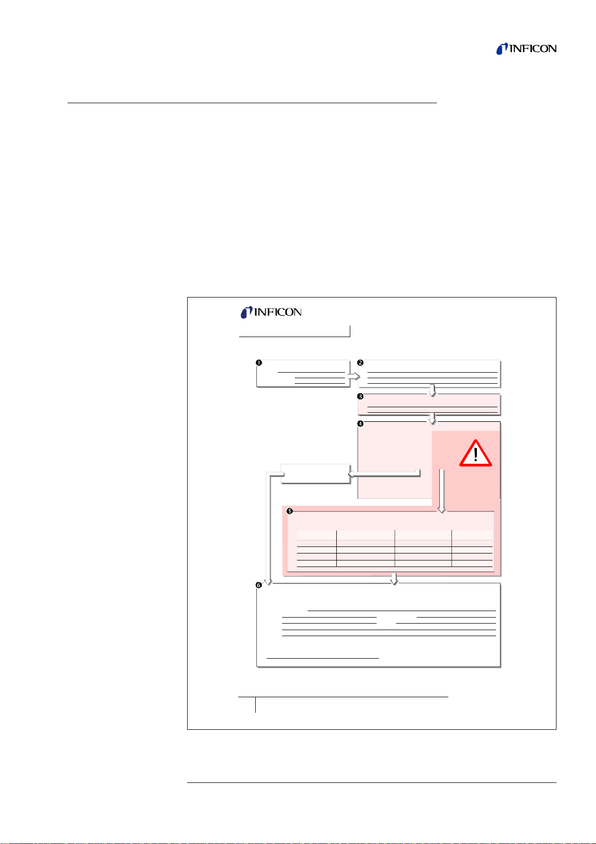
zisa01e1-a
Declaration of Contamination
Legally binding declaration:
I/we hereby declare that the information on this form is complete and accurate and that I/we will assume any further costs that may
arise. The contaminated product will be dispatched in accordance with the applicable regulations.
Organization/company
Address Post code, place
Phone Fax
Email
Name
Date and legally binding signature Company stamp
1) or not containing any amount
of hazardous residues that
exceed the permissible ex posure limits
Process related contamination of product:
toxic no 1) yes
caustic no 1) yes
biological hazard no yes 2)
explosive no yes 2)
radioactive no yes 2)
other harmful substances no1) yes
The service, repair, and/or disposal of vacuum equipment and components will only be carried out if a correctly completed declaration has
been submitted. Non-completion will result in delay.
This declaration may only be completed (in block letters) and signed by authorized and qualified staff.
Copies:
Original for addressee - 1 copy for accompanying documents - 1 copy for file of sender
Harmful substances, gases and/or by-products
Please list all substances, gases, and by-products which the product may have come into contact with:
Trade/product name
Chemical name
(or symbol)
Precautions associated
with substance
Action if human contact
Description of product
Type
Article Number
Serial Number
Reason for return
Operating fluid(s) used (Must be drained before shipping.)
The product is free of any substances which are damaging to
health yes
This form can be downloaded
from our website.
2) Products thus contami nated will not be ac cepted without written
evidence of decontami nation!
If the HLD5000 is returned to INFICON, indicate whether the leak detector is free of
substances damaging to hea lth or whether it is contamin ated. If it is contaminated
also indicate the nature of the hazard. INFICON will return any leak detector without
a "Declaration of Contamination” to the sender’s address.
Before returning any equipment, please get in touch with the Service Center for the
purpose of discussing the issue (RMA number, for example).
General
We reserve the right to modify the design and the specified data. The illustrations are
not binding.
Please refer to national shipping requirements - Dangerous Goods - due to
pressurized calibrated leak.
kina40e 01.fm technical handbook(1007)
Fig. 1-1 Declaration of Contamination (original size see attachment)
www.inficon.com leakdetection.service@inficon.co
General 1-5
Page 14
1.4.1 Service Centers
Algeria jhj@agramkow.dk Finland jhj@agramkow.dk
Agramkow
Sonderborg
Belarus akhlestine@gertnergroup.de France Christophe.Zaffanella@oerlikon.com
Gertner Service
Moscow
Belgium leakdetection.service@inficon.com Germany leakdetection.service@inficon.com
INFICON GmbH
Cologne
Brazil fernandoz@prestvacuo.com.br Hungary adam.lovics@kon-trade.hu
PV Pest Vácuo Ltda.
Santa de Parnaíba
Bulgaria leakdetection.service@inficon.com India asdash@hotmail.com
INFICON GmbH
Cologne
Canada reachus@vpcinc.ca Ireland reach.unitedkingdom@inficon.com
Vacuum Products Canada Ltd.
Ontario
Central America infoqro@meisa.com Italy davide.giovanetti@inficon.com
MEISA S.a. de C.V.
Querètaro
China reach.china@inficon.com Israel urimark@mark-tec.co.il
INFICON LTD
Hong Kong
INFICON LTD
Beijing
INFICON LTD
Guangzhou
INFICON LTD
Shanghai
Czech Republic filip.lisec@inficon.com Korea reach.korea@inficon.com
INFICON GmbH
Pilsen
Denmark jhj@agramkow.dk INFICON Ltd.
Agramkow
Sonderborg
Egypt jhj@agramkow.dk Latvia leakdetection.service@inficon.com
Agramkow
Sonderborg
Estonia leakdetection.service@inficon.com Lithuania leakdetection.service@inficon.com
INFICON GmbH
Cologne
Phone: +45 741 236 36
Fax: +45 744 336 46
Phone: +7 959 319 646
Fax: +7 959 319 645
Phone: +49 221 34742222
Fax: +49 221 347 42221
Phone: +55 114 154 4888
Fax: +55 114 154 4888
Phone: +49 221 34742222
Fax: +49 221 347 42221
Phone: +905.672.7704
Fax: +905.672.2249
Phone: +52 44 22 25 42 80
Fax: +52 44 22 25 41 57
Phone: +852.2862.8863
Fax: +852.2865.6883
Phone: +86.10.6590.0164
Fax: +86.10.6590.0521
Phone: +86.20.8723.6889
Fax: +86.20.8723.6003
Phone: +86.21.6209.3094
Fax: +86.21.6295.2852
Phone +420 734 331 758
Fax: +420 604 203 037
Phone: +45 744 336 36
Fax: +45 744 336 46
Phone: +45 741 236 36
Fax: +45 744 336 46
Phone: +49 221 34742222
Fax: +49 221 347 42221
Agramkow
Sonderborg
OLV France
Orsay
INFICON GmbH
Cologne
Kontrade
Budaörs
Dashpute
400 064
INFICON
Blackburn
INFICON GmbH
Castelnuovo
Mark Technologies Ltd.
Kiriat Ono
Japan reach.japan@inficon.com
INFICON Co. Ltd.
Yokohama
INFICON Ltd.
Sungnam city
Suwon City
INFICON Ltd.
Cheonan City
INFICON GmbH
Cologne
INFICON GmbH
Cologne
Phone: +45 741 236 36
Fax: +45 744 336 46
Phone: +33 476 351 584
Fax: +33 476 351 584
Phone: +49 221 34742222
Fax: +49 221 347 42221
Phone: +36 23 50 38 80
Fax: +36 23 50 38 96
Phone: +91 22 888 0324
Fax: +91 22 888 0324
Phone: +44 1254 678 250
Fax: +44 1254 698 577
Phone: +39 045 6 40 25 56
Fax: +39 045 6 40 24 21
Phone: +972 35 34 68 22
Fax: +972 35 34 25 89
Phone: +81.45.471.3396
Fax: +81.45.471.3387
Phone: +82 312 062 890
Fax: +82 312 063 058
Phone: +82 312 062 890
Fax: +82 312 063 058
Phone: +82 312 062 890
Fax: +82 312 063 058
Phone: +49 221 34742222
Fax: +49 221 347 42221
Phone: +49 221 34742222
Fax: +49 221 347 42221
1-6 General
kina40e 01.fm technical handbook(1007)
Page 15
Mexico infoqro@meisa.com Spain richard.cunill@leyboldoptics.com
MEISA S.a. de C.V.
Querètaro
Phone: +52 442 225 42 80
Fax: +52 442 225 41 57
Leybold Optics Ibérica
Barcelona
Phone: +34 93 66 60 778
Fax: +34 93 66 64 612
Netherlands leakdetection.service@inficon.com Sweden jhj@agramkow.dk
INFICON GmbH
Cologne
Phone: +49 221 347 42222
Fax: +49 221 347 42221
Agramkow
Sonderborg
Phone: +45 741 236 36
Fax: +45 744 336 46
Norway jhj@agramkow.dk Syria leakdetection.service@inficon.com
Agramkow
Sonderborg
Phone: +45 741 236 36
Fax: +45 744 336 46
INFICON GmbH
Cologne
Phone: +49 221 34742222
Fax: +49 221 347 42221
Poland kamola@vakpol.com Taiwan Susan.Chang@inficon.com
VAK-POL & GAZ Sp. zo.o
Pulawy
Phone: +48 60 23 15 212
Fax: +48 60 23 15 212
INFICON Company Limited
Chupei City, HsinChu Hsien
Phone: +886.3.5525.828
Fax: +886.3.5525.829
Portugal ana.correia@zickermann.pt Tunisia leakdetection.service@inficon.com
Sociedade Zickermann
S.A.R.L, Lissabon
Phone: +351 21 322 41 60
Fax: +351 21 346 91 29
INFICON GmbH
Cologne
Phone: +49 221 34742222
Fax: +49 221 347 42221
Republic of South Africa vacuquip@hotmail.com Turkey jhj@agramkow.dk
Vacuquip
Randburg
Phone: +27 73 15 78 355 Agramkow
Sonderborg
Phone: +45 741 236 36
Fax: +45 744 336 46
Russia leakdetection.service@inficon.com Ukraine leakdetection.service@inficon.com
INFICON GmbH
Cologne
Phone: +49 221 34742222
Fax: +49 221 347 42221
INFICON GmbH
Cologne
Phone: +49 221 34742222
Fax: +49 221 347 42221
Singapore reach.singapore@inficon.com United Kingdom reach.unitedkingdom@inficon.com
INFICON PTE LTD.
Singapur
Phone: +65.890.6250
Fax: +65.890.6266
INFICON
Blackburn
Phone: +44 1254 678 250
Fax: +44 1254 698 577
Slovakia filip.lisec@inficon.com United Arab Emirates leakdetection.service@inficon.com
INFICON GmbH
Pilsen
Phone +420 734 331 758
Fax: +420 604 203 037
INFICON GmbH
Cologne
Phone: +49 221 34742222
Fax: +49 221 347 42221
Slovenia medivak@siol.net USA service.usa@inficon.com
Medivac
Ljubljani
South America except Brazil infoqro@meisa.com Inficon Inc.
MEISA S.a. de C.V.
Querètaro
Phone: +386 15 63 91 50
Fax: +386 17 22 04 51
Phone: +52 44 22 12 36 15
Fax: +52 44 22 12 19 40
Inficon Inc.
East Syracuse, NY
San Jose, CA
Inficon Inc.
Austin, TX
Phone: +1.315.434.1167
Fax: +1.315.434.2551
Phone: +1.408.361.1200
Fax: +1.408.362.1556
Phone: +1.512.448.0488
Fax: +1.512.448.0398
kina40e 01.fm technical handbook(1007)
General 1-7
Page 16
1.5 Notes on How to Read this Manual
Caution
Warning
Important remarks concerning operational safety and protection are emphazised as
follows:
Indicates procedures that must strictly be observed to prevent damage to or
destruction of the HLD5000 leak detector.
Indicates procedures that must be strictly observed to prevent haza rd s to per sons.
Notice Indicates special technical requirements that the user must comply with.
The references to diagrams, e.g. (2-2/1) consist of the Chapter No., Fig. No. and the
Item No. in that order. For example: (2-2/1) refers to item 1 in the second figure of
chapter 2, i.e. the calibration port for the calibrated leak.
1.5.1 Definition of Terms
Rejection leak rate Trigger level or leak rate limit setting at which the test sample
Default status State the HLD5000 is in when leaving the factory.
Main menu This is the first menu which is displayed after switching on the
Submenus All further menus which can be accessed from the main
Menu item A single menu line.
Standby mode Resting status of the HLD5000. The pump and valve system
PIN Personal password number so as to be able to prevent
reaches the limit between good and bad. If the reject le ak rate
is exceeded, in the measurement mode the HLD5000 will
output a visually and audibly apparent alarm.
HLD5000.
menu.
is off in this mode.
unauthorised changes to leak detector settings.
1-8 General
kina40e 01.fm technical handbook(1007)
Page 17

1.6 Installation
Warning
1.6.1 Unpacking
Unpack the HLD5000 immediately after delivery, even if it is to be installed later on.
Examine the shipping container for any external damage. Completely remove the
packaging materials.
Notice Retain the shipping container and the packaging materials in the event of
complaints about damage.
Check that the HLD5000 is complete and carefully examine the HLD5000 visually.
If any damage is discovered, report it immediately to the forwarding agent and
insurer. If the damaged part has to be replaced, please contact the orders
department.
Remove the protection foil from the display.
After switching on the HLD5000 the programmed type of gas has to appear in the
upper left corner of the display and has to match with the sticker on the probe.
1.6.2 Mechanical Connections
In order to operate the HLD5000, a sniffer line must be connected. The connection
(Fig. 2-1/2) is located on the left side on the front of the main unit. Insert the plug into
the opening until it engages. For this the red ma rk o n the p l ug must cor re spon d with
the mark on the main unit.
To disconnect the plug, retract the coupling and remove the probe’s line.
1.6.3 Electrical Connection
The HLD5000 is equipped with a wide voltage ra nge power supply unit cover ing 100
V to 230 V (± 10 %, 50/60 Hz). The mains cord is connected to the mains socket (Fig.
2-1/7) on the rear of the main unit. A fuse (Fig. 2-1/8) for each conductor of the mains
cord has been integrated in the mains socket (Fig. 2-1/7) of the main unit.
Only mains cords having three conductors with a protective ground conductor may
be used. The HLD5000 must never be operated with a disconnected protective
ground conductor.
1.6.4 Wall Mounting
kina40e 01.fm technical handbook(1007)
A fixture at the bottom of the HLD5000 (Fig. 2-2/7) allows mounting the leak detector
on walls, (for example due to space restrictions). It is recommended to place the
HLD5000 high enough (at least 2 m) so that the display points down wards.
General 1-9
Page 18

1.6.5 RS232 Interface
Caution
The HLD5000 is equipped with a RS232 in terface which is located on the rear of the
main unit under the mains connection (Fig. 1-2). This interface is of the DCE type
(Data Communications Equipment) and allows the connection of a PC for mo nitoring
and data logging. The connection is provided through a commercially available SubD plug. For further information see "Interface Description HLD5000” (kins40e1).
Fig. 1-2 RS232 Interface
Pos. Description Pos. Description
1. Mains Socket 3. RS232 Interface
2. Mains Fuses
1.6.6 The Sniffer Tip
1.6.6.1 Changing the sniffer tip
To change the complete sniffer tip (see Fig. 1-3) loosen the nut connection (Fig. 1-3 )
and pull off the sniffer tip. Insert the new sniffer tip with the guide pin (Fig. 1-3/2)
running in the groove, and firmly retighten the nut.
Ensure, that the filter cartridge (Fig. 1-3/1) is clean, and replace it as required.
Before loosening the connecting nut, you must switch off the HLD5000 first. When
exchanging the sniffer tip make sure th at no dust or particles of dirt enter into the
opening.
1-10 General
kina40e 01.fm technical handbook(1007)
Page 19

Fig. 1-3 Sniffer tip with accessories
Pos. Description Pos. Description
1 filter cartridge 5 filter holder
2 guide pin 6 extension
3 connecting nut 7 water protection tip
4 sniffer tip 8 holder for extension
1.6.6.2 Use of the flexible sniffer tip
In addition to the rigid sniffer tip included with th e HLD5000, also a 400 mm long
flexible tip (Cat. No. 511-024) may be used. By correspondingly bendin g the flexible
tip, areas which are hard to access can be reached.
1.6.6.3 Use of the sniffer tip extension
For the purpose of measuring refrigerant concentrations (e.g. in the case of already
packaged test objects in the package), for reaching points which are difficult to
access or for finding large leaks quickly a flexible extension (Cat. No. 511-020) may
be screwed onto the filter holder (see Fig. Fig. 1- 3/5). Make sure that the plastic hose
surrounds holder and filter holder. The 400 mm long extension (Fig. 1-3/6) may be
pulled out after pressing down the ring of th e h older ( Fig . 1- 3/8) ; if required , you ca n
cut the extension down to the required length. The tip facing the test object must
always be cut at an angle of approximately 45°.
1.6.6.4 Use of water protection tip
In order to avoid sucking in liquids, the water protection tip (Fig. 1- 3/7) (Cat. No. 511-
025) may be screwed onto the filter holder. The water protection tip will prevent
liquids in up to about 3 mm in he ight (the e.g. puddles of condensed water) fr om
being sucked.
kina40e 01.fm technical handbook(1007)
Fig. 1-4 Water protection tip fitted
General 1-11
Page 20

In order to prevent the entry of liquids when working on moist test objects, the handle
should not be held vertically with the sniffer tip facing up, this avoids liquids in the
water protection tip from flowing back into the sensor. If, even so, liquid has been
sucked into the sensor system, let the HLD5000 run for about 10 minutes (n ot in the
standby mode) to pump out the liquid from the sensor system via th e supply pump in
the main unit.
1-12 General
kina40e 01.fm technical handbook(1007)
Page 21

2 Principle of Operation
2.1 Description
The HLD5000 is capable of detecting, measuring and displaying quantitatively the
refrigerant, C0
analyzer.
The important subassemblies of the HLD5000 are:
• the sensor system subassembly located in the probe
• the pump system together with the electric and electronic subassemblies
accommodated in the main unit
Infrared light from a corresponding source is made to pass through a cell through
which also the gas taken in by the HLD5000 flows. This light is filtered so that only
light having a specific wavelength is allowed to pass on to an infrared light detector.
If in the presence of a leak, refrigerant, SF
cell, the infrared light is partly absorbed by the refrigerant. The intensity of the light
arriving at the detector is thus reduced.
The change in the intensity of the light is amplified electronically, converted from
analogue to digital and is displayed visually and audibly after processing by the
microprocessor in the main unit. By means of a reference measurement based on
the ambient air, the background concentration of the test gas or other interfering
gases is taken into account when processing the measured data.
or SF6 sucked in through the probe’s line by means of its infrared gas
2
or CO2 enters with the air taken into the
6
Fig. 2-1 Flow of the gas within the HLD5000
kina40e 02.fm technical handbook(1007)
Principle of Operation 2-1
Page 22

2.2 HLD5000 Overview
Fig. 2-2 Overview
Pos. Description Pos. Description
1 Calibration port 9 RS232 Interface
2 Connection for the probe’s line 10 Mount
3 Keys for operating the menu 11 Built-in calibrated leak
4 LC display (not for SF
5 LED display 12 Air filter
6 Mains switch 13 Probe
7 Mains socket 14 Sniffer tip
8Mains fuses 15Eye
/CO2 version)
6
2-2 Principle of Operation
kina40e 02.fm technical handbook(1007)
Page 23

3 Operating the HLD5000
Caution
Caution
Caution
3.1 Start-up
Put the HLD5000 in place (see also chapter wall installation), connect the sniffer line
and the mains cord.
The HLD5000 will only operate after having connected the sniffer line first.
Do not place the HLD5000 on hot surfaces.
Notice In the default setting the serial numbers of the main unit and the probe has
to match.
Press the mains switch (Fig. 3-2/6) to switch on the HLD5000. The HLD5000 will take
about 30 seconds to warm up as indicated by the display.
During warm-up the sniffer tip must not be inserted in the test leak opening.
Otherwise, the internal calibration will be disabled and an error message will be
displayed.
In the default setting, the HLD5000 uses English menu text. To switch to another
language press the keys
the chosen language and confirm with “OK”.
After the warm-up phase of the HLD5000, an audible signal is produced and the leak
detector will be ready to make measurements. The green LED (Fig. 3-3/2) in the
probe indicates that the HLD5000 is ready to make measurements. The type of gas
to which the HLD5000 has been programmed as well as the un it of measurement for
the leak rate (factory default: g/a) is indicated on the display (Fig. 3-2/4). Moreover,
the type of probe (detectable gas) to which the HLD5000 has been set up is indicate d
on the sticker on the probe.
The main unit is usable for all refrigerants, the detectable refrigerant is determined
by the probe.
kina40e 03.fm technical handbook(1007)
PROGRAMM, OPTIONS AND LANGUAGE. Press the button for
Operating the HLD5000 3-1
Page 24

3.2 Working with the HLD5000
Warning
Caution
Provided the HLD5000 has been adapted to the specific requirements of the
application (see Chapter 4) and calibrate d accordingly, a le ak test can be per formed
as follows:
Lead the probe tip as close as possible to the locations that are to be tested. If
needed, the tip may even touch the unit under test.
Danger of electric shock.
• Do not touch live parts with the sniffer tip.
• Test samples need to be disconnected from electricity before leak testing.
Under all circumstances the intake of liquids which may still be present on the
surface of the test object has to be avoided.
In the case of moist test objects (e.g. condensed water) the use of the water
protection tip is recommended (see Chapter 1.6.6).
If a welded seam or a joint needs to be tested, the tip of the probe should be moved
no faster than 2.5 cm/s (1 inch/s) across the location which is to be tested. The
distance between probe tip and unit under test should be kept as small as possible.
In the case of probing a specific location, the tip should remain in place briefly (at
least 1 s).
The HLD5000 compares the measured leak rates with the rejection leak rates
(trigger levels) set up as described in Chapter 4.1. If the measured leak rate exceed s
the rejection leak rate, then more than half of the yellow lamps (LED) on the arcshaped display (Fig. 3-2/5) will come on and an audible alarm is released.
Due to its working principle (see Chapter 2.1) background concentrations in the
environment are suppressed and do not cause an alarm. Refrigerant clouds in front
of large leaks will also be considered a background concentration. Different from the
behavior of its predecessor HLD4000, the HLD5000 will not alarm when only
approaching leaks from a larger distance. Larger leaks will also only be detected
when close to the leak and thus, can be localized reliably.
Notice If you can not guarantee getting close enough to the leak (as described
above) larger leaks may be missed. In this case, please use the flexible
sniffer tip extension (Cat. no. 511-020) which is delivered with the
HLD5000. For this application the extension tip can be cut down to 100 mm
(4 in.) length for easier handling. (see Chapter 1.6.6.3)
Depending on the measurement mode (see Chapter 4.1) the test should be repeated
with the key of the probe pres sed to precis ely pinpoint the location of the leak or to
double check the rejection leak rate.
3-2 Operating the HLD5000
kina40e 03.fm technical handbook(1007)
Page 25

3.3 Controls and their Function
3.3.1 Overview of the Controls and Display Components
The controls and display components of the HLD5000, with the exception of the
button and the LED at the probe, are all located at the main unit (Fig. 3-2).
3.3.2 Mains Switch
The HLD5000 is switched on and off via the mains switch (Fig. 3-2/6). In addition, it
can enter a standby mode which can be activated automatically or manually.
3.3.3 LED Display of the HLD5000
The arc-shaped LED display (Fig. 3-2/5) is divided into a green half (on the left) and
a yellow half (on the right). The relative leak rates as detected are indicated here. The
center of the arc of LEDs where the LEDs change from green to yellow indica tes the
rejection leak rate which has been set up. Leak rates which remain below the
rejection leak rate are indicated by the green LEDs, higher leak rates are indicated
by the yellow LEDs. The last yellow LED corresponds to approximately 200% of the
trigger level entered.
3.3.4 LC Display
In its default setting the LC display (Fig. 3-2/4) will show the measuring screen after
switching on:
• The type of gas, for example R134a, which is detected is indicated at the top on
the left side.
• If a universal Smart probe is connected the designation “Smart” is displayed
below the gas type.
• The currently entered rejection leak rate (trigger level), for example 09.0 g/a is
indicated at the top on the right
• The actual leak rate currently detected is displayed in the center of the display.
(The lower display limit is 0.3 g/a (0.02 oz / yr) for single gas probes, and 0.2 g/a
(0.02 oz / yr) for the Smart probe.)
kina40e 03.fm technical handbook(1007)
Operating the HLD5000 3-3
Page 26

Fig. 3-1
Pos. Description Pos. Description
1 Gas type of probe 4 Info button
2 Trigger 5 Display of leak rate
3 Standby button 6 Menu button
• The left lower button opens the main menu.
• The right lower button opens the info page HLD5000 to sleep mode.
3-4 Operating the HLD5000
kina40e 03.fm technical handbook(1007)
Page 27

Fig. 3-2 Main unit
Pos. Description Pos. Description
1 Calibration port 4 LC display
2 Connection for the probe 5 LED display (leak rate display)
3 Keys to operate the menuto 4 and on
the right from 5 to 8)
(Key numbering on the left side is from
top to bottom from 1
6 mains switch
3.3.5 Probe
The probe (see Fig. 3-3) is firmly attached to the probe’s line; only the sniffer, tip
which is available in different lengths, can be exchanged.
Located on the probe are an LED (Fig. 3-3/2) and a button (Fig. 3-3/3). The LED
indicates the following operating modes:
Operating condition Description
off: HLD5000 not ready to measure
green (steady): normal operating mode / no errors
green, flashing: error / measurement not possible or
accuracy of the measurements can not be
guaranteed.
kina40e 03.fm technical handbook(1007)
Operating the HLD5000 3-5
Page 28

Operating condition Description
yellow (steady): measured leak rate >40% but below the
rejection leak rate.
yellow, flashing fast: the measured leak rate has exceeded the
rejection leak rate.
yellow / green, flashing: after a restart no link between probe and
main unit has yet been established.
Fig. 3-3 hand unit
Pos. Description Pos. Description
1 filter holder 3 button
2LED 4 eye
The button is provided to select the different testing modes, see Chapter 4 and to
calibrate the HLD5000, see Chapter 4.5.
The eye (see Fig. 3-3/4) serves the purpose of hanging the handle, for example,
when not being used.
3-6 Operating the HLD5000
kina40e 03.fm technical handbook(1007)
Page 29

4 HLD5000 Settings (Menu Structure)
Fig. 4-1 Structure of the menu
Via the menu, the HLD5000 may be adapted to the specific operating conditions or
requirements in each case.
The menu opens by pressing the
PROGRAM key.
Operating
STANDBY sets the HLD5000 into the standby mode in which the valve and
pump are switched off.
INFO contains set-up information on important parameters and settings.
The entries for the parameters are made according to th e same scheme. After having
selected the menupoint which is to be set up, for example
desired numerical value is selected. If, for example, an 8 is to be entered, press the
key next to the numbers 8 and 9, thereafter the number 8 may be selected. In order
to skip a setting or to return, the keys next to the arrows ← and → can be pressed.
In order to save changed entries into the menu, these must be acknowledged by
"OK”. Entries may be cancelled at any time by pressing "ESC”. In such a case the
new entries are not saved.
All parameters necessary to operate the HLD5000 are saved even after powering
down the HLD5000.
4.1 Description of the Menu "Program”
This menu consists of the following items:
TRIGGER
VOLUME
CONTRAST
OPTIONS
TRIGGER → LEVEL, the
CAL
LIST
ERRORS
kina40e 04.fm technical handbook(1007)
INFO
HLD5000 Settings (Menu Structure) 4-1
Page 30

4.1.1 TRIGGER
LEVEL (rejection leak rate)
Through this menu item the following settings can be entered:
LEVEL (rejection leak rate)
ALT LEVEL
GAS TYPE (with Smart probe only)
BUTTON
UNIT
These settings are described in the following:
The "
LEVEL” menu item is selected when wanting to enter the leak rate at which the
units under test shall be rejected. The level may be set 1 g/a (0.04 oz/yr) (depending
on type of gas) and 50 g/a (1.76 oz/yr). For further units please refer to the following
table:
Unit Lower display limit Upper display limit
g/a (0.5) 1.0 50.0
mbar l/s
lb/yr (1) 2 x 10
oz/yr (0.02) 0.04 1.76
Pa m
-1
3xs-1
4x10
4x10
-6
-3
-7
3.9 x 10
1.0 x 10
3.9 x 10
-4
-1
-5
(Values in parenthesis are for Smart probe only)
ALT LEVEL
Entry of the alternative rejection rate. This rejection rate is used only when the key
on the handle has been programmed to "
entered representing a percen tage of the value for
absolute terms, for example 10 g/a.
GAS TYPE (For Smart
probe only)
The HLD5000 with Smart probe offers 5 pre-programmed gases to choose from.
When opening the gas type menu a list of these five gases plus three user-definable
gases is displayed. The bottom two buttons on the left side of the display allow to
scroll the list. The currently selected gas is highlighted by inverted colors.
When switching between the pre-programmed gases the HLD50 00 does not re quire
to be recalibrated. The HLD5000 will automatically adjust for the different sensitivities
the Smart probe has for the different gases. However, the trigger value will stay the
same.
When choosing a user definable gas the HLD5000 can either be calibrated externally
or a calibration factor can be entered to enable a calibration with the built-in
calibrated leak. These factors have to be determined for each additional gas and may
be obtained from INFICON on request in most cases. When not entering a calibration
ALT” (see below). This setting may be
LEVEL, for example 50 %, or in
4-2 HLD5000 Settings (Menu Structure)
kina40e 04.fm technical handbook(1007)
Page 31

BUTTON
factor a request for external calibration will be issued after selecting this gas. If a
calibration factor is entered the HLD5000 may be calibrated with the internal
calibrated leak as for all other gases from the list.
The HLD5000 permits the entry of different configurations as to the operation of the
button in the probe so as to allow different working and test methods to be
implemented:
UNIT
"OFF" "
OFF” means that the button in the probe is disabled ( except du ring the
calibration process, see Chapter 4.5.2). The rejection leak rate (
set up under the menu item "
TRIGGER” is used, the alternative rejection
LEVEL)
leak rate does not apply here.
"ALT" "
ALT” should be selected if a unit under test is to be tested at two
different points at differing sensitivities. If the button on the probe is not
pressed the rejection leak rate set up under "
LEVEL” will apply. When
operating the button, then the alternative rejection leak rate will apply
(as set up under "
"SEARCH" With the setting "
ALT LEVEL”).
SEARCH” selected it is possible to quickly sniff the unit
under test at a high sensitivity defined by the HLD5000 with the button
on the probe not pressed. As soon as the HLD5000 has detected a
leak, the button may then be pressed to determine if the leak found
exceeds the rejection leak rate as set up under "
LEVEL”. The alternative
rejection leak rate is not available in this mode. In the main menu and
with this setting, Search (Test) will be displayed when button on at the
handle is not pressed.
Here the unit of measurement required for the measurements can be selected. One
may select from g/a; mbar x l /s; lb/yr; oz/yr and Pa x m
3
/s.
For the Smart probe only g/a, oz/yr and lb/yr are available. When switching from a
pre-programmed gas to a user-definable gas the HLD5000 will default to g/a.
4.1.2 VOLUME
Here the loudspeaker may be switched "OFF” or "ON”. When selecting "ON” the
volume may be adjusted from 1 (quiet) to 20 (loud) with the aid of the arrows ↑ and ↓.
With the Test button the selected volume can be checked.
The error sound is a two-tone sound.
4.1.3 CONTRAST
Through this function one may set up the contrast for the LC display. For this press
the keys "brighter” or "darker” as required until the desired level of brightness has
kina40e 04.fm technical handbook(1007)
been attained. The range spans from 1 to 99.
HLD5000 Settings (Menu Structure) 4-3
Page 32

4.1.4 OPTIONS
Caution
LANGUAGE
If by accident the display has been set too bright or too dark so that it can not be re ad
anymore, this may be changed as follows:
Switch off the HLD5000 and switch it on again. During the warm up phase hold the
menu key 3 or 7 pressed (see Fig. 3-2) until the display can be read properly again.
(Keys are numbered beginning at the top left side with No. 1, going down and end
with No. 8 at the button on the right side.) This value is saved permanently on ly after
having acknowledged it through the menu item "
confirmed, the former setting will apply once again after switching on the HLD5000
once more.
Under "OPTIONS” the following parameters can be set up:
Here one may select the language for the menus and messages which are displayed.
Choose between English, Spanish, French, German, Chinese and Japanese
(Katakana) language.
If by accident Chinese or Katakana language is chosen, press the buttons 2 and 6 to
get back to the english menu.
CONTRAST”. If this setting is not
CLOCK
CHANGE PIN
Here date and time may be set. The date setting format is day, month and year
(DD.MM.YY), the time format is the 24 hour format in hours and minutes (HH.MM).
Through this function it is possible to define or change the PIN (password).
The PIN (password) protects the program menu from unauthorized access.
A new PIN is defined by entering a four digit number twice in succession.
The PIN function can be disabled by entering 0000 as the PIN, using the steps
defined above. Enabling is possible at any time by proceeding as described above.
Under all circumstances memorize the new PIN!
The PIN can only be reset by INFICON’s service organization.
4-4 HLD5000 Settings (Menu Structure)
kina40e 04.fm technical handbook(1007)
Page 33

REQUEST
AUTO STANDBY
Request for
calibration
Request for calibration. The HLD5000 can be set up to remind the
operator at regular intervals to run a calibration. Through this function
the automatic request to calibrate can be sw itched on o r off wher eby
the time interval can be selected in increments of 30 minutes. The
setting is entered through the keys ↑ and ↓, and a period ranging
between 30 minutes and 24 hours may be selected. After the entered
time span has elapsed, the HLD5000 will sound an alarm and indicate
on the display a request to recalibrate.
Request for
filter
replacement
The HLD5000 can be set up to remind the operator at regular intervals
to replace the filter holder at the sniffer tip. By selecting
ON or OFF the
function can be enabled or disabled. When enabled the message
„Please replace filter holder!“ will be displayed every 40 hours of
operation. In this case please r eplace the filter holder (see Chapter
6.2.1) and acknowledge the message. The next request for filter
replacement will pop up after further 40 hours of operation. As factory
default the function is enabled.
The HLD5000 offers the possibility of automatically reverting to the standby mode
during pauses or periods during which it is not used. A time span ranging between 1
and 15 minutes may be entered. If the HLD5000 is not used for a period of time
longer than the one set up here, the leak detector will thereafter revert automatically
to the standby mode.
When lifting the probe, the HLD5000 will automatically revert to normal operation and
will be ready to make measurements within 2 seconds.
RS232
Through this menu, the settings for the RS232 interface of the HLD5000 can be
entered.
Protocol Selection of the interface protocol: "OFF”, "Normal” or "Simple”.
If the RS232 interface is not used, the "OFF” setting is recommend ed
to exclude the possibility of any interference.
For further details on the interface protocol refer to "Interface
Description HLD5000 (kins40e1)”.
Baud rate Entry of the baud rate for the RS232 interface. Available settings are
300, 600 1200, 2400, 4800 or 9600 baud. The default setting is 9600
baud.
External Calibrated Leak
Here the setting for the leak rate of the external leak can be entered.
The setting is performed as described on Chapter 4.4 and has to be confirmed with
“OK“. If for example the external leak rate is entered in g/a and cha nged into another
unit of measurement, the HLD5000 converts the leak rate g/a into the new unit of
kina40e 04.fm technical handbook(1007)
measurement.
HLD5000 Settings (Menu Structure) 4-5
Page 34

4.1.5 CAL
Through this menu item the HLD5000 may be calibrated with an external test leak.
The SF
calibrated leak. When pushing the „
the display: “Sniff external test leak“, the appointed leak rate and the type of
refrigerant of the external test leak.
The calibration is performed as follows:
• Enter the leak rate of the external test leak under the menu item “Ext. Test leak“.
• Go back to menu item “CAL“.
• Hold the sniffer tip against the gas outlet of the external leak until the LED signal
• Confirm with probe button.
• Keep the sniffer tip on the outlet until the information “calibration successful“ or a
The HLD5000 is calibrated now.
4.1.6 LIST ERRORS
Here a list containing the 12 most recent error messag es and the acknowledge ment
of error messages is displayed. The time, date and an error code is displayed, and
via the key "View” the error with time and date can be displayed in plain text.
and CO2 version of the HLD5000 can only be calibrated using an external
6
is stable.
beep is displayed.
CAL“ button the following information appears in
4.1.7 INFO
Main Unit Info
The error code consists of a letter and a two digit number.
Meaning of the letter:
• E: Error / warning was displayed
• R: Error / warning has been removed (remove)
• M: General message, for example "power up” (message)
The two digit number in the error code corresponds to th e number given in the table ,
found in the repair instruction (doc. no. kipa40e).
The INFO key provides important information to the user relating to the entered
parameters and the operating modes of the HLD5000. By scrolling forward and
backward using the arrow keys the 6 different information pages can be displayed.
Detailed in the following is the information which can be accessed:
• Internal housing temperature
• Number of operating hours of the main unit
• Software version number for the main unit
4-6 HLD5000 Settings (Menu Structure)
kina40e 04.fm technical handbook(1007)
Page 35

Probe Info 1
Probe Info 2
CAL Info
• Internal sensitivity factor S for monitoring the sensor circuitry
• Differential pressures Δp1and Δp2 to monitor the gas flows in the measurement
and reference lines
• Channel used by the AD converter
• Number of operating hours for the probe
• Software version number for the probe
• HEX Code of probe
• Contains information for service people
•CAL factor
• Phase
• Sensor factor e.g. R134a → R404A
• Factor which is multiplied with the internal test leak to get the equivalent leak rate
for the measured gas.
Test leak info
U / I-Info
• Leak rate for the calibrated leak normalized to 20 °C
• Leak rate of the calibrated leak compensated for temperature and type of gas
• + 12 Volt supply voltage (U+)
• - 12 Volt supply voltage (U-)
• Supply voltage for the infrared light source in the probe (U light)
• Current flow through the infrared light source in the probe (I light)
• Probe test voltage to monitor the voltage supply (U probe)
kina40e 04.fm technical handbook(1007)
HLD5000 Settings (Menu Structure) 4-7
Page 36

4.2 Description of the Menu Item INFO
The INFO menu item contains set-up information relating to the following
parameters. By scrolling back and forth you can switch between „Setup-Info 1“ and
„Setup-Info 2“.
Setup-Info 1: Trigger level
Alt. trigger level
Button
Volume
Setup-Info 2: Date
Time
Next calibration
TRIGGER LEVEL
Displays the selected rejection leak rate, for example 10 g/a.
ALT. TRIGGER LEVEL
Displays the selected alternative rejection leak rate. Values which were entered in %
are converted to absolute values.
BUTTON
Informs about the selected setting (
VOLUME
Indicates the volume setting for the loudspeaker.
DATE
Indicates the current date as day, month and year.
TIME
Indicates the current time as hours, minutes and seconds.
NEXT CALIBRATION
Indicates how long it will be (hours and minutes) until the reminder to calibrate will be
displayed.
OFF, ALT, TEST) for the button in the probe.
4-8 HLD5000 Settings (Menu Structure)
kina40e 04.fm technical handbook(1007)
Page 37

4.3 Menu Item STANDBY
Pressing the standby key makes the HLD5000 enter the standby mode during which
the valve in the handle is disabled and the diaphragm pump is shut down.
In this mode, no leak rate measurements can be run.
When letting the HLD5000 enter the standby mode by operating the key "Standby”
and not through the automatic shut down feature (can be configured through the
menu item "
reactivated by pressing any key.
After this time, operating any key on the HLD5000 or moving the handle will reset the
leak detector back to the measurement mode.
AUTO STANDBY”) during the first 25 seconds, the HLD5000 can only be
4.4 Selecting the gas type
For selective, single gas probes (Cat. No. 510-010 through 510-016 or sniffer line
Cat. No. 511-030 to 511-036) the detected gas type can be changed by connecting
a different, selective sniffer line.
For the Smart probe the detectable gas can be selected from a list of 5 preprogrammed gases plus three user-definable gases. (See „Gas Type“ in Chapter
4.1.1)
4.5 Calibration
The HLD5000 is equipped with a built-in calibrated leak by means of which the leak
detector may be calibrated. The service life of the calibrated leak is about 2 years.
Three months before expiration of the calibrated leak a message will be displayed
reminding the operator to replace it.
Notice The SF
calibrated leak. Calibration will only be possible using an external
calibrated leak (see „Gas Type“ in Chapter 4.1.1).
Notice When operating the Smart probe user definable gases will require to be
calibrated with an external test leak until a calibration factor is entered for
this gas type.
Notice Replacement leaks should not be purchased in advance of their need as
they have a limited lifetime. Any leaks being held in stock should be kept in
a cool place.
Notice In order to ensure accurate measurements wait for at least five minutes
after switching on before running a calibration .
and CO2 version of the HLD5000 is not equipped with its own
6
kina40e 04.fm technical handbook(1007)
HLD5000 Settings (Menu Structure) 4-9
Page 38

4.5.1 Checking the Calibration
A calibration can be checked by inserting the probe tip into the calibration port
without depressing the button on the probe. A message will be displayed indicating
whether or not the calibration is still OK (refer also to Chapter 4.1.4, manual
calibration).
On the leak rate display, two LEDs to the left and right of the 100% mark will flash. If
the measured value is outside this mark, a recalibration will be required. The
currently measured value is indicated by two moving LEDs just like during the
calibration process. Moreover, the calibration status is indicated on the display.
A recalibration can be started immediately by pressing the button, and the probe tip
does not have to be removed from the calibration port.
If a recalibration is required, this is indicated on the display and by an audible tone.
During the check, the probe must be held still and straight.
4.5.2 Calibrating the HLD5000 with the COOL-Check
To calibrate the HLD5000, press the button on the probe and insert the sniffer tip into
the calibration port at the front of the main unit. The HLD5000 will then start the
calibration process automatically. During the calibration process it is not necessary
to keep the button on the probe pressed. The individual phases of the calibration
process are indicated on the display which also informs the user about a successful
calibration.
Notice During the calibration process, the probe must be held still and straight,
otherwise no calibration will be possible.
Notice During the calibration, the opening for the calibrated leak should not be
exposed to strong air flows (from air-conditioning units, for example).
Notice When performing the calibration using the extension tip Cat. No. 511-020
the insert should be used in the opening of the calib r at ed leak so as to
ensure that the tip is properly centered in the opening.
Fig. 4-2 Opening at the calibration port
4-10 HLD5000 Settings (Menu Structure)
kina40e 04.fm technical handbook(1007)
Page 39

Fig. 4-3 Calibrated leak
4.5.3 Calibrated leak (COOL-Check)
The calibrated leak is located in the bottom of the main unit. It consists of a gas
canister with a printed circuit board attached to the bottom.
When the calibrated leak is nearly empty, the message "Leak nearly empty. Please
replace!” will be displayed.
The user will have to replace the calibrated leak within two to three months before
the calibrated leak will be completely empty.
How to replace the COOL-Check is described in Chapter 6.2.5.
Notice Replacement leaks should not be purchased in advance of their need as
they have a limited lifetime.
4.6 Shutting Down
The HLD5000 may be switched off at any time by operating the mains switch
independently of the operating mode it is in.
All parameters are saved when the HLD5000 is powered down.
4.7 Switching probes
To convert the HLD5000 to a different probe shut down the HLD5000, unplug the
current sniffer line and connect a different sniffer line with a different probe. The
probe type will be indicated in the upper left corner of the display after restarting the
HLD5000.
kina40e 04.fm technical handbook(1007)
HLD5000 Settings (Menu Structure) 4-11
Page 40

4-12 HLD5000 Settings (Menu Structure)
kina40e 04.fm technical handbook(1007)
Page 41

5 Messages
While operating in the leak detection mode, the display will provide information which
will support the operator using the HLD5000. Besides messages relating to leak
detector settings also warnings and error messages may be displayed.
The HLD5000 is equipped with comprehensive self-diagnostic means. If a fault
condition is detected by the controller board this is indicated via the display to the
operator.
Errors are events which force an interruption to the measurement sequence and
which the HLD5000 is not capable of remedying on its own. Errors are displayed in
plain text on the display. The error sound is a two-tone sound.
The error message can be erased by pressing the "OK” key.
As long as an error status exists, a warning triangle comes up in the lower line of the
display.
An overview over the error messages which may occur while the machine is in use
and possible remedies are listed below.
A list of all error messages as well a notes for troubleshooting is provided in the
Repair Instructions (kipa40e1).
Displayed message Explanation/possible cause Remedies
Leak nearly empty
Please replace!
Probe not connected! There is no data connection to the sniffer
Leak temperature is too high! Main Unit is standing on a hot surface
Leak temperature too low! Ambient temperature too low Increase temperature around the main
Housing temperature too high! Ambient temperature too high
Flow at measuring line too low! Measuring line is blocked
Leak at measuring line! Measuring line is leaking
Service life of the Cool Check is less than
3 months
Cool Check is nearly empty
Set on wrong date
probe
Sniffer Probe is not connected
If LED at Sniffer Probe is off:
processor in the Sniffer Probe does not
run
Ambient temperature too high
Fan defect or blocked
Differential sensor is broken
One of the hoses to differential sensor is
leaking
Differential sensor is broken
Replace Cool Check
Program Main Unit with new date
Check the sniffer line
Check the LEMO plug or change sniffer
line
Decrease the temperature around the
main unit
unit
Decrease temperature around the main
unit
Change the fan
Change the filters of the sniffer tip
Change the CPU-Board (Sniffer Probe)
Check the gasket of sniffer tip
Check or change the hoses to
differential sensor
Change the CPU-Board (Sniffer Probe)
Flow at reference line too low! Reference line is blocked
Filter is clogged
kina40e 05.fm technical handbook(1007)
Differential sensor is broken
Check the sniffer line, change the sniffer
tip
Change the filters of the sniffer tip
Change the CPU-Board (Sniffer Probe)
Messages 5-1
Page 42

Displayed message Explanation/possible cause Remedies
Leak at reference line! Reference line is leaking
One of the hoses to differential sensor is
leaking
Differential sensor is broken
Leak empty. Please replace! Cool Check empty
Wrong date (main unit)
Change the sniffer line
Check or change the hoses to the
differential sensor
Change the CPU-Board (Sniffer Probe)
Change the Cool Check
Adjust new date (main unit)
Change Cool Check
Sensor sensitivity too low! Optical cell is contaminated with water Depending on the quantity of water let
run the HLD5000 from 1 minute to 2
hours
Light barrier dirty Dust has accumulated in the test leak
opening and is interrupting the light
barrier.
Turn off HLD5000. Blow out the test leak
opening with compressed air. Restart
HLD5000.
Calibration with internal test leak can be
started from the main menu manually.
Calibration proof not possible
Wrong gas type in internal test leak
Calibration not possible
Wrong gas type in internal test leak
Smart probe programmed to userdefinable gas
or SF6 probe connected
CO
2
Smart probe programmed to userdefinable gas
or SF6 probe connected
CO
2
Check calibration with external test leak
Check calibration with external test leak
Warning 02: light barrier dirty Light barrier dirty Clean test port of calibrated leak
If problem persists confirm and calibrate
with external leak until light barrier is
replaced
Calibration time out limit exceeded Light barrier dirty Clean test port of calibrated leak
If problem persists shut down the
HLD5000 and restart. Calibrate with
external leak afterwards until light
barrier is replaced
5-2 Messages
kina40e 05.fm technical handbook(1007)
Page 43

6 Maintenance
6.1 INFICON Service
If an the HLD5000 is returned to INFICON, please indicate whether it is free of
substances damaging to hea lth or whether it is contamin ated. If it is contaminated
also indicate the nature of the hazard. For this you must use a form pre-prepared,
which we will send to you upon request or which you may copy from this manual.
The form is called: "Declaration of Contamination of Vacuum Equipment and
Components”.
Affix this form to the HLD5000 or enclose it with the leak detector. This Declaration
of Contamination is required by us to meet the requirements of the laws and to
protect our staff.
INFICON will return any leak detectors without a "Declaration of Contamination" to
the sender’s address.
6.2 Maintenance Work
No fixed maintenance intervals have been specified for the HLD5000. The work
described in the following will only have to be done as required.
6.2.1 Replacing the Filters
The filters serve the purpose of filtering the air taken in. In order not to obstruct the
airflow and to prevent the HLD5000 from being contaminated all filters should be
exchanged preventatively.
There are three filters in the HLD5000, two within the sniffer tip filtering the air intake
through the sniffer line and one air filter at the bottom of the housing.
6.2.1.1 Exchanging the filters in the sniffer line
We recommend to exchange the filter holder at the probe tip preventatively at least
once a week and the filter cartridg e at the bottom of the sniffer tip at least once a
month.
If the function “Request for filter replacement“ is enabled, the message „Please
replace filter holder!“ will be displayed every 40 hours of operation. After replacing
the filter holder and acknowledging the message the internal counter for this function
will be reset and the message will pop up after another 40 hours of operation. Any
dirty or clogged filter in the sniffer line will lead to the same error message as a dirty
tip filter holder. In dirty conditions the error message “flow at measuring line too low”
or “flow at reference line too low” may occur before expiration of these time limits. On
occurrence of these error messages please exchange the tip filter holder first. If this
does not fix the problem, please also exchange the filter cartridge.
kina40e 06.fm technical handbook(1007)
Maintenance 6-1
Page 44

Caution
Before exchanging any of the sniffer line filters please switch off the HLD5000.
Caution
When replacing filters please make sure that no particles enter into the intake
opening.
The fine filters at the probe tip are firmly built into the filter holder. To replace the filter
holder please:
1 Unscrew the filter holder from the probe tip
2 Screw on a new filter holder.
Replacement filter holders are available for order in sets of 20 pieces as
Cat. No. 511-027.
The fine filters at the bottom of the sniffer tip are firmly built into the filter cartridge.
To exchange the filter cartridge please:
1 Loosen the screw at the bottom of the sniffer tip and detach the sniffer tip from the
probe handle
2 Take off the filter cartridge from the bottom of the sniffer tip
3 Place a new one on the two ends of the measurement and reference line
4 Attach the sniffer tip back onto the probe handle and retighten the screw at the
bottom of the sniffer tip.
Replacement filter cartridges are available for order in sets of 20 pieces as Cat. No.
511-018.
5 Exchanging the air filter at the bottom of the housing.
The air filter at the bottom of the housing sh ould be replaced once it has turned dark
gray or deposits of dirt are clearly visible on the filter.
Before replacing the air filter at the bottom of the housing please disconnect the
HLD5000.
1 Switch off the HLD5000 off and pull the mains plug
2 Unscrew the screws in the middle of the filter
3 Remove the filter and depending on how dirty it is either replace it or clean it (for
example with compressed air or a brush)
4 Insert the filter once more
5 Tighten the screw
Replacement air filters are available for order as Cat.No. 200 000 086.
kina40e 06.fm technical handbook(1007)
6-2 Maintenance
Page 45

6.2.2 Cleaning the Opening of the Calibrated Leak
Warning
In order to prevent the light barrier in the opening of the calibrated leak from being
interrupted by dirt, the opening should be blown out with clean compressed air
regularly.
6.2.3 Cleaning
The housing of the HLD5000 is made of plastic. Therefore to clean the housing use
cleaning only agents which are recommended to clean plastic surfaces (for example
mild household cleaning agents). Do not use any solvents which attack plastic
materials.
6.2.4 Replacing Fuses
To replace the fuses remove the mains cord first.
The fuse holder (Fig. 2-2/8) of the HLD5000 is located below the ma ins socket on the
rear of the main unit. To replace the fuses proceed as follows:
1 Press down the pin in center and pull the fuse holder out.
2 Pull the fuses out and check these.
3 If required insert a new fuse. In any case two fuses of the same rating will have to be
inserted. The mains fuses required are slow-blow T 1 A (Ø 5 x 20 mm).
4 Insert the fuse holder once more and press it home until the securing pin engages.
After having replaced the fuses, reconnect the mains cord to the HLD5000 and
switch on the leak detector.
6.2.5 Replacing the Calibrated Leak (not for SF6 / CO2 version)
The calibrated leak should be rep laced two to three months at the latest after the
message " Leak nearly empty. Please replace!” has been displayed. The calibrated
leak is replaced as follows:
1 Switch off the HLD5000 off and pull the mains plug.
2 Turn the main unit on its side to expose the base.
3 Turn the yellow plastic screw back completely.
4 Carefully remove the calibrated leak. Don’t damage the cable.
5 Pull off the plug (blue) from the calibrated leak’s printed circuit board.
kina40e 06.fm technical handbook(1007)
6 Take a new calibrated leak and insert the plug into the socket.
Maintenance 6-3
Page 46

7 Insert the new calibrated leak and feed the cable with the plug through the hole.
8 Secure with the screw. Please make sure that the rubber seal is firmly in place and
that the outlet opening of the calibrated leak is positioned approximately at the
middle of the opening for the calibrated leak.
9 Switch off the HLD5000 on and run a new calibration after about 5 minutes.
A residual amount of refrigerant might be left un der pressure (more than 5 bar) in the
canister of the empty leak standard. Therefore the COOL-Check must be disposed
PROPERLY - following the local, state and national regulations - or must be sent
back to INFICON / your supplier.
6-4 Maintenance
kina40e 06.fm technical handbook(1007)
Page 47

INFICON GmbH
Bonner Str. 498,50968 Cologne, Germany
Tel: +49 221 3474 2222 Fax: +49 221 3474 2221
m
zisa01e1-a
Declaration of Contamination
Legally binding declaration:
I/we hereby declare that the information on this form is complete and accurate and that I/we will assume any further costs that may
arise. The contaminated product will be dispatched in accordance with the applicable regulations.
Organization/company
Address Post code, place
Phone Fax
Email
Name
Date and legally binding signature Company stamp
1) or not containing any amount
of hazardous residues that
exceed the permissible ex posure limits
Process related contamination of product:
toxic no 1) yes
caustic no 1) yes
biological hazard no
yes 2)
explosive no
yes 2)
radioactive n o
yes 2)
other harmful substances no1) yes
The service, repair, and/or disposal of vacuum equipment and components will only be carried out if a correctly completed declaration has
been submitted. Non-completion will result in delay.
This declaration may only be completed (in block letters) and signed by authorized and qualified staff.
Copies:
Original for addressee - 1 copy for accompanying documents - 1 copy for file of sender
Harmful substances, gases and/or by-products
Please list all substances, gases, and by-products which the product may have come into contact with:
Trade/product name
Chemical name
(or symbol)
Precautions associated
with substance
Action if human contact
Description of product
Type
Article Number
Serial Number
Reason for return
Operating fluid(s) used (Must be drained before shipping.)
The product is free of any substances which are damaging to
health yes
This form can be downloaded
from our website.
2) Products thus contam i nated will not be ac cepted without written
evidence of decontam i nation!
Fig. 6-1 Declaration of contamination
kina40e 06.fm technical handbook(1007)
www.inficon.com leakdetection.service@inficon.co
Maintenance 6-5
Page 48

Fig. 6-2 Declaration of Conformity
6-6 Maintenance
kina40e 06.fm technical handbook(1007)
Page 49

Appendix
A
alarm 1-3
alarm, audible 3-2
B
baud rate 4-5
BUTTON 4-8
button 4-3
C
calibrated leak 4-11, 6-3
calibrated leak, external 4-5
calibration 4-5–4-6, 4-8–4-9
calibration factor 4-2, 4-9
checking the calibration 4-10
control component 3-3
COOL-Check 4-10
D
G
gas type 1-9
gases 2-1, 4-2, 4-9
I
installation 1-9
interface 1-10, 4-5
interface description 1-3, 1-10
L
language 4-4
leak test 3-2
LED 3-3, 3-5, 4-10
LED, green 3-1
LED, yellow 3-2
level (ALT) 4-2
loudspeaker 4-3
M
data communications equipment 1-10
data, electrical 1-2
data, other 1-2
data, physical 1-2
dimensions 1-2
display component 3-3
display limit, lower 4-2
display limit, upper 4-2
E
error 4-6
extension 1-11, 3-2
F
filter 1-3, 6-1
Filter cartridge 1-4
filter cartridge 6-1
filter holder 6-2
filter replacement 4-5
kina40eSIX.fm technical handbook(1007)
mains supply voltage 1-2
mains switch 3-3
maintenance 6-1
measured leak rate 3-2
measurement range 1-2
menu 1-8
menu structure 4-1
P
Pin, change 4-4
power supply unit 1-9
probe 3-1, 3-5
R
refrigerant 1-2
rejection leak rate 4-2
replacing fuses 6-3
request 4-5
request to calibrate 4-5
response time 1-2
Appendix A-1
Page 50

RS232 1-10, 4-5
S
sensitivity 4-3, 4-7
Settings HLD5000 4-1
shipping container 1-9
sniffer tip 0-6, 1-10, 4-6, 6-2
solvent 6-3
standby 1-2, 4-1, 4-5, 4-9
T
test leak, internal 4-10
trigger 3-3, 4-1–4-2, 4-8
trigger level setting 1-2
U
unit 3-1, 4-3, 4-5
V
volume 4-3, 4-8
W
warm-up phase 3-1
water protection tip 0-7, 3-2
Weight 1-2
A-2 Appendix
kina40eSIX.fm technical handbook(1007)
Page 51

kina40eSIX.fm technical handbook(1007)
Appendix A-3
Page 52

INFICON GmbH, Bonner Strasse 498, D-50968 Cologne, Germany
Phone: +49 (0)221 347-40 Fax: +49 (0)221 347-41429 E-mail: leakdetection@inficon.com
UNITED STATES TAIWAN JAPAN KOREA SINGAPORE GERMANY FRANCE UNITED KINGDOM HONG KONG
Visit our website for contact information and other sales offices worldwide. www.inficon.com
Dokument: kina22e1-g (1007)
 Loading...