

Page 1
OPERATING MANUAL
jinb80e1-h (1011) Translation of the original manual
Catalog-No.
550-300
550-310
550-330
from software version 1.7
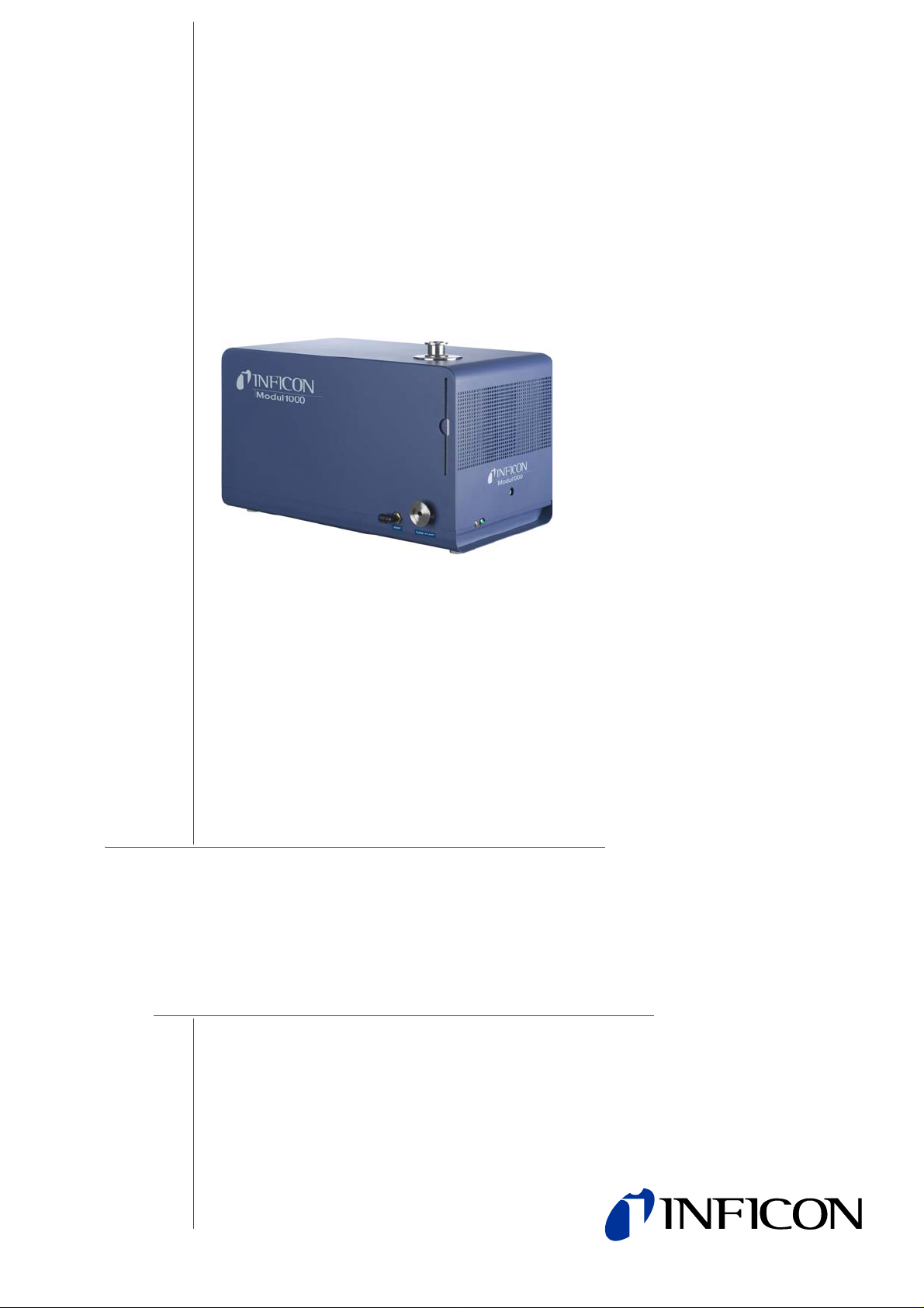
Modul1000
Modular Leak Detector
Page 2

Legal notice
INFICON GmbH
Bonner Straße 498
50968 Cologne
Germany
0-2
Copyright
©
2010 INFICON GmbH, Cologne. This document may only be reproduced
in any form with the permission of INFICON GmbH, Cologne.
jinb80e1-h Operating Manual(1011)
Page 3

Content
1 Operating instructions 1-5
1.1 How to use this manual 1-5
1.2 Warning and danger symbols 1-5
1.3 Graphic conventions 1-6
1.4 Definition of Terms 1-6
2 Important safety instructions 2-1
2.1 Intended use 2-1
2.2 User requirements 2-1
2.3 Restrictions of use 2-2
2.4 Hazards in the event of intended use 2-2
3 Description of equipment 3-1
3.1 The housing 3-1
3.2 Interfaces 3-3
3.3 Operating options 3-3
3.3.1 Desktop operation 3-4
3.3.2 Installation in switch cabinet 3-4
3.3.3 Remote control RC1000 3-5
3.4 Scope of delivery 3-6
3.5 Accessories 3-6
3.5.1 Sniffer line SL200 3-6
3.5.2 Test chamber TC1000 3-6
3.5.3 Set of male connectors for Interfaces 3-7
4 Installation 4-1
4.1 Mechanical Installation 4-1
4.2 Electrical installation 4-1
4.2.1 Mains socket 4-1
4.2.2 Electrical interfaces 4-2
4.2.3 Vacuum connections 4-6
5 Working Modes 5-1
5.1 Vacuum 5-1
5.2 Partial Flow Mode 5-2
5.3 Auto Leak Test 5-3
5.3.1 Auto Leak Test Settings 5-3
5.4 Commander mode 5-4
5.4.1 Design of a leak detector system 5-5
5.4.2 Test sequence of events 5-6
jinb80e1-h Operating Manual(1011)
5.5 Sniff mode tips 5-8
Content 1-1
Page 4

6 Operation 6-1
6.1 Switching ON 6-1
6.2 Status LED 6-1
6.3 Control 6-2
6.4 Control commands 6-3
6.5 Display 6-6
6.6 Calibration in Vacuum mode 6-9
6.7 Calibration in Sniff mode 6-10
6.8 Calibration in Auto Leak Test 6-11
6.9 Calibration in Commander mode 6-11
6.10 Machine factor 6-12
6.11 Menu structure 6-13
6.12 Explanation of Menu Items 6-15
6.12.1 Main menu
6.12.2 Main menu
6.12.3 Main menu
6.12.4 Main menu
6.12.5 Main Menu
6.12.6 Main menu
6.12.6.1 Main menu
6.12.6.2 Main menu
6.12.6.3 Main menu
6.12.6.4 Main menu
6.12.6.5 Main menu
6.12.6.6 Main menu
6.12.6.7 Main menu
6.12.7 Main menu
6.12.8 Main menu
→
Return 6-15
→
View 6-15
→
Mode 6-16
→
Trigger & Alarms 6-16
→
Calibration (CAL) Mode Vacuum 6-18
→
Settings 6-20
→
Settings→ Vacuum settings 6-20
→
Settings→ Zero & Background 6-23
→
Settings→ Mass 6-23
→
Settings→ Interfaces 6-23
→
Settings→ Miscellaneous 6-26
→
Settings→ Load/Save Parameters 6-27
→
Settings→Monitoring 6-28
→
Info 6-30
→
Access Control 6-31
7 Maintenance tasks 7-1
7.1 Maintenance and service at INFICON 7-1
7.2 General Maintenance Instructions 7-1
7.3 Maintenance schedule 7-3
7.4 Maintenance intervals 7-3
7.5 Description of the maintenance work 7-5
7.5.1 Opening of the Device 7-6
7.6 TMH 071 Replace the Lubricant Reservoir 7-7
7.7 Fuse replacement 7-10
7.7.1 Overview on Electrical Fuses 7-10
7.7.2 Replace mains fuse 7-11
7.7.3 Replace fuses on interface board 7-12
7.8 Replacing of parameter memory (I•STICK) 7-13
7.9 Replace Vent Filter 7-14
jinb80e1-h Operating Manual(1011)
1-2 Content
Page 5

8 Transport and disposal 8-1
8.1 Transporting after Contamination 8-1
8.2 Disposal 8-2
9 Technical Data 9-1
9.1 Technical data of components 9-1
9.1.1 Power supply 9-1
9.1.2 Weight / dimensions 9-1
9.1.3 Characteristics 9-1
9.1.4 Environmental Conditions 9-2
9.2 Control via the PLC inputs and outputs 9-3
9.2.1 PLC inputs 9-3
9.2.2 PLC Outputs 9-6
9.3 The digital valve outputs 9-9
9.4 Analogue Output 9-10
9.4.1 Configuration of the analogue outputs 9-10
9.5 Pin Assignments 9-13
9.5.1 PLC IN / AUDIO 9-13
9.5.2 PLC OUT 9-15
9.5.3 Pressure Gauge 9-16
9.5.4 Valves 9-19
9.5.5 Recorder 9-21
9.6 Installation diagram of the control unit for rackinstallation 9-22
9.7 Commander mode 9-23
9.8 CE-Certificate 9-24
10 Error Messages and Warnings 10-1
11 Ordering Information 11-1
11.1 Service Centres World Wide 11-3
INDEX 11-5
jinb80e1-h Operating Manual(1011)
Content 1-3
Page 6

1-4 Content
jinb80e1-h Operating Manual(1011)
Page 7
1 Operating instructions
STO P
Danger
Warning
Caution
1.1 How to use this manual
• Read this manual before using Modul1000.
• Keep the manual so that you can use it anytime.
• Enclose the operating manual if the device is ever passed on to third parties.
1.2 Warning and danger symbols
This symbol refers to an immediate hazard, which may result in fatal or serious
injuries (crippling).
This symbol refers to a possibly hazardous situation, which may result in fatal or
serious injuries.
This symbol refers to a possibly hazardous situation, which may result in slight
injuries.
This symbol is also used to alert you to the risk of material or environmental
damage.
jinb80e1-h Operating Manual(1011)
Operating instructions 1-5
Page 8

1.3 Graphic conventions
Notice: Points to very useful pieces of information.
1 Points to an operation that you have to perform.
⇒ Points to the result of an operation you accomplished.
→ Points to the button you have to press.
• Shows a listing.
1.4 Definition of Terms
Autotune / Mass alignment
The Modul1000 adjusts its tuning voltage to determine the optimal voltage for peak
efficiency.
Autoranging
The range of the pre-amplifier is selected automatically. The Autoranging feature of
the Modul1000 covers the entire range or leak rate s depending on the selected operating mode. Vacuum mode or Sniff mode Not only the leak rate signal, but also the
pressure in the test sample (inlet pressure PE) and the fore-vacuum pressure (PV)
are used for control purposes.
Auto zero
Determination and automatic adaptation of the helium background in the Vacuum
mode. Through this function, the internal zero level of the instrument is determined
which is then subtracted from the current leak rate signal. Th is functio n is run dur ing
the calibration process or when operating the start push-button, provided the
Modul1000 has been running previously for at least 20 seconds in the Standby or
Vent mode. If the helium background previously suppressed should drop, the zero
level will be adapted automatically.
Fore pressure
Fore pressure between turbo pump and fore pressure pump.
Internal helium background
The existing helium partial pressure in the measurement system. The level of the
internal helium background is measured in the Stand-by mode and subtracted from
the measured signal. (see above: Auto zero)
jinb80e1-h Operating Manual(1011)
1-6 Operating instructions
Page 9

Minimum detectable leak rate
The smallest leak rate the Modul1000 is able to detect.
-12
(5x10
mbar l/s).
Menu
The menu allows the user to program the Modul1000 accord ing to the requirements.
The menu has a tree structure.
As-delivered condition
The default settings of the Modul1000 are as delivered by the factory.
Standby
The Modul1000 is ready for operation.
MEASURE
MEASURE mode is when the Modul1000 has achieved a pressure better than the
crossover and the unit is sampling the gas load for helium leak rate.
jinb80e1-h Operating Manual(1011)
Operating instructions 1-7
Page 10

1-8 Operating instructions
jinb80e1-h Operating Manual(1011)
Page 11

2 Important safety instructions
2.1 Intended use
The Modul1000 is intended to be used for the leak test under vacuum. With the
sniffer version of Modul1000 (Catalogue-No. 550-310), it is also possible to locate
leaks in the test sample.
The Modul1000 may only be use d for leak tests with helium and hydrogen. It may
only be used in dry rooms and on dry surfaces.
Only use INFICON accessories.
The intended use includes:
• the compliance with the technical data and the ambient conditions,
• the use of standard and original accessories,
• consideration of this documentation and the observation of the included
instructions and directives.
2.2 User requirements
The Modul1000 must only be connected and operated by properly trained staff.
• Get used to the functioning of the device. Only connect and operate the device
after reading and understanding the manual.
• Consult local, State, and national agencies regarding specific requirements and
regulations.
• Address any further safety, operation and / or maintenance questions to our
nearest office.
jinb80e1-h Operating Manual(1011)
Important safety instructions 2-1
Page 12
2.3 Restrictions of use
STO P
Danger
STO P
Danger
STO P
Danger
STO P
Danger
STO P
Danger
Danger of fatal injuries due to explosion.
Switch on and operate the Modul1000 only outside of explosive areas.
Risk of dangerous gases.
The device is not suitable for caustic, toxic and explosive substances.
Only use this device for detecting harmless substances.
2.4 Hazards in the event of intended use
Before installing the Modul1000, carefully read all safety instructions and make sure
that you have properly understood them.
Danger
Danger of fatal injuries due to explosion.
When explosive gases are used as test gas, the gas container could explode.
Avoid flames and sparks, keep ignition sources far away from the device.
Danger of fatal injuries due to electric shock.
Keep the sniffer tip away from live parts.
Danger of fatal injuries due to electric shock!
Connect the Modul1000 properly with the 3-core power cable and then connect the
PE-line to earth.
2-2 Important safety instructions
jinb80e1-h Operating Manual(1011)
Page 13
STO P
Danger
Danger of fatal injuries due to electric shock!
STO P
Danger
STO P
Danger
STO P
Danger
Disconnect the Modul1000 from the power supply before the you open it.
Risk of injury and contamination caused by toxic gases.
Only use the Modul1000 for detecting harmless substances.
The device is not suitable for toxic, caustic, micro-biologic, explosive, radioactive or
other hazardous substances.
Contact the manufacturer if you plan to use the device for such substances.
Danger of fatal injuries due to implosion.
Components which are not pressure-resistant, can burst cause through implosion .
Only connect containers and pa rts to the inlet f lang e of M odu l1000 whic h are s uit-
able for vacuum.
Danger of fatal injuries due to strong permanent magnets.
Magnets can impact the functioning of pacemakers.
If you wear a pacemaker, keep away from the device as far as it is specified in the
manufacturer's instructions.
jinb80e1-h Operating Manual(1011)
Important safety instructions 2-3
Page 14
Warning
Warning
Warning
Warning
Warning
Warning
Warning
Risk of injuries through rotating parts
Before a transport leave the Modul1000 switch ed off fo r at lea st 20 min ut es .
Danger of injury through dropping devices.
Two people should carry the Modul1000 or use a lifting device.
Back injury through heavy loads.
Two people should carry the Modul1000 or use a lifting device.
Injury to health due to emissions and fumes of oil-sealed pumps.
Before it is operated in closed rooms, the oil sealed fore-pressure pump, if used,
has to be connected to an exhaust gas pipe.
Danger of fatal injuries due to electric shock!
Only operate the Modul1000 in buildings and on dry surfaces.
Risk of injury due to sucking inlet flange
If the vacuum function of the Modul1000 is activated, body parts which are close to
the inlet flange can be sucked in.
Keep your body away from the inlet flange.
2-4 Important safety instructions
jinb80e1-h Operating Manual(1011)
Page 15

Warning
Supposed risk
If it can be supposed that safe operation is not ensured any more, the device must
be switched off and must be secured against accidental switching on.
If this happens, contact the INFICON service people.
Notice: Such a problem could occur,
• when the device has visible damages,
• when liquid has penetrated into the dev ice,
• when the device does not operate any mo re ,
• after long storage time under unfavourable conditions,
• after strong transport conditions
jinb80e1-h Operating Manual(1011)
Important safety instructions 2-5
Page 16
Caution
Caution
Caution
Caution
Caution
Caution
Caution
The Modul1000 is destructed by aggressive substances.
Avoid contact to bases, acids, solvents and do not expose it to extreme climatic
conditions.
The Modul1000 may be damaged by improper transport conditions.
Only use this device for detecting helium and hydrogen.
Use a filter in the inlet of the Modul1000 to avoid dirt from getting into the vacuum
system.
The electronic system of the Modul1000 may be damaged by the wrong supply
voltage.
Check, if the local power supply voltage complies with the required supply voltag e
of the device.
The electronic system of the Modul1000 may be damaged by too high voltages.
The digital inputs are designed for maximum 30 V.
The electronic system of the Modul1000 may be damaged by too high electric
loads.
The relay outputs should be connected to maximum 60V DC or 25 V AC / 1A at
ohmic load. The semiconductor outputs should only be connected to 30V / 1A.
The electronic system of the Modul1000 can be destroyed when devices are
connected to the Modul1000 whose electronic circuitr y is not safely separated from
the mains.
Only connect devices to the Modul1000 whose connections are safely separated
from the power system.
jinb80e1-h Operating Manual(1011)
2-6 Important safety instructions
Page 17
Caution
The turbo-molecular pump may be damaged by jerky movements.
Caution
Caution
Caution
Caution
Caution
During operation, move the Modul1000 only carefully and smoothly.
Risk of damage.
The Modul1000 may be damaged by excess heat.
Pay attention to the serve messages and replace the dirty air filters.
Risk of damage.
The Modul1000 can overheat and fail when the openings are plugged.
Provide for free openings for air inlet and outlet.
The Modul1000 can be damaged when liquid gets into it.
If liquid has entered the Modul1000, do not switch it on and contact the INFICON-
Service.
The Modul1000 may be damaged by being stored in unfavourable conditions (too
damp, too hot, too cold, too high above sea level) for months or years. (refer to
Technical Data!)
If the Modul1000 has been store d und er su ch cond itions , leav e it swit ched off a nd
contact the INFICON Service Department.
Risk of damage.
The Modul1000 may be damaged by improper transport conditions.
Always transport the Modul1000 in its original pack ag ing .
jinb80e1-h Operating Manual(1011)
Important safety instructions 2-7
Page 18

2-8 Important safety instructions
jinb80e1-h Operating Manual(1011)
Page 19
3 Description of equipment
1
2
3
4
5
6
7
8
The Modul1000 is a helium leak detector which has been designed to be insta lled in
leak test work stations or integrated machines.
The analysis system with turbo-molecularpump and a complete control unit are integrated in a compact housing. Depending on the set operating mode, the Mo dul100 0
can execute overriding control functions in a leak test system.
Multiple signal and status outputs allow the universal integration in existing or new
system versions.
The operating parameters set by the user are stored in a separate memory module
(I•STICK) which can be withdrawn easily.
All device configurations and the necessary maintenance works can be performed
without opening the device.
To generate the fore-vacuum required for the operation of the turbo-molecula r pump,
as well as for evacuation of th e conn ected test sample, a fore-vacuum pump with a
pumping speed of >2 m³/h has to be connected. It must be able to generate a final
pressure of <1x10
3.1 The housing
-2
mbar.
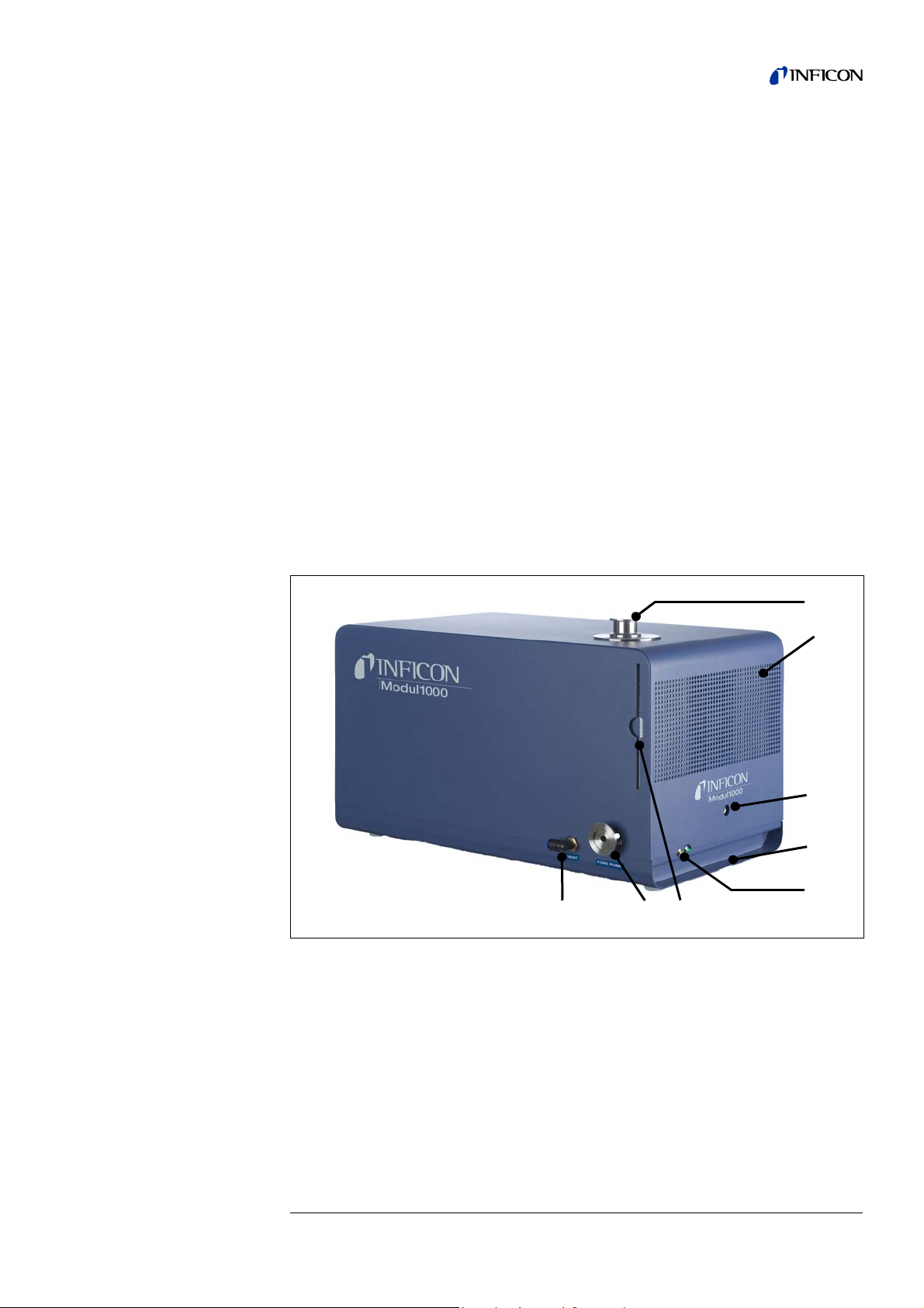
Fig. 3-1 Left side view and front view.
Item Description Item Description
1 Inlet flange DN25 KF 6 air filter
2 Loudspeaker / Air inlet Mains fuses
3 Openings for unlocking 7 Connection DN25 KF for
the cover Backing Pump
4 Recess handles 8 Vent connection FESTO coupling
jinb80e1-h Operating Manual(1011)
5 Status LED Hose 8 mm
Description of equipment 3-1
Page 20
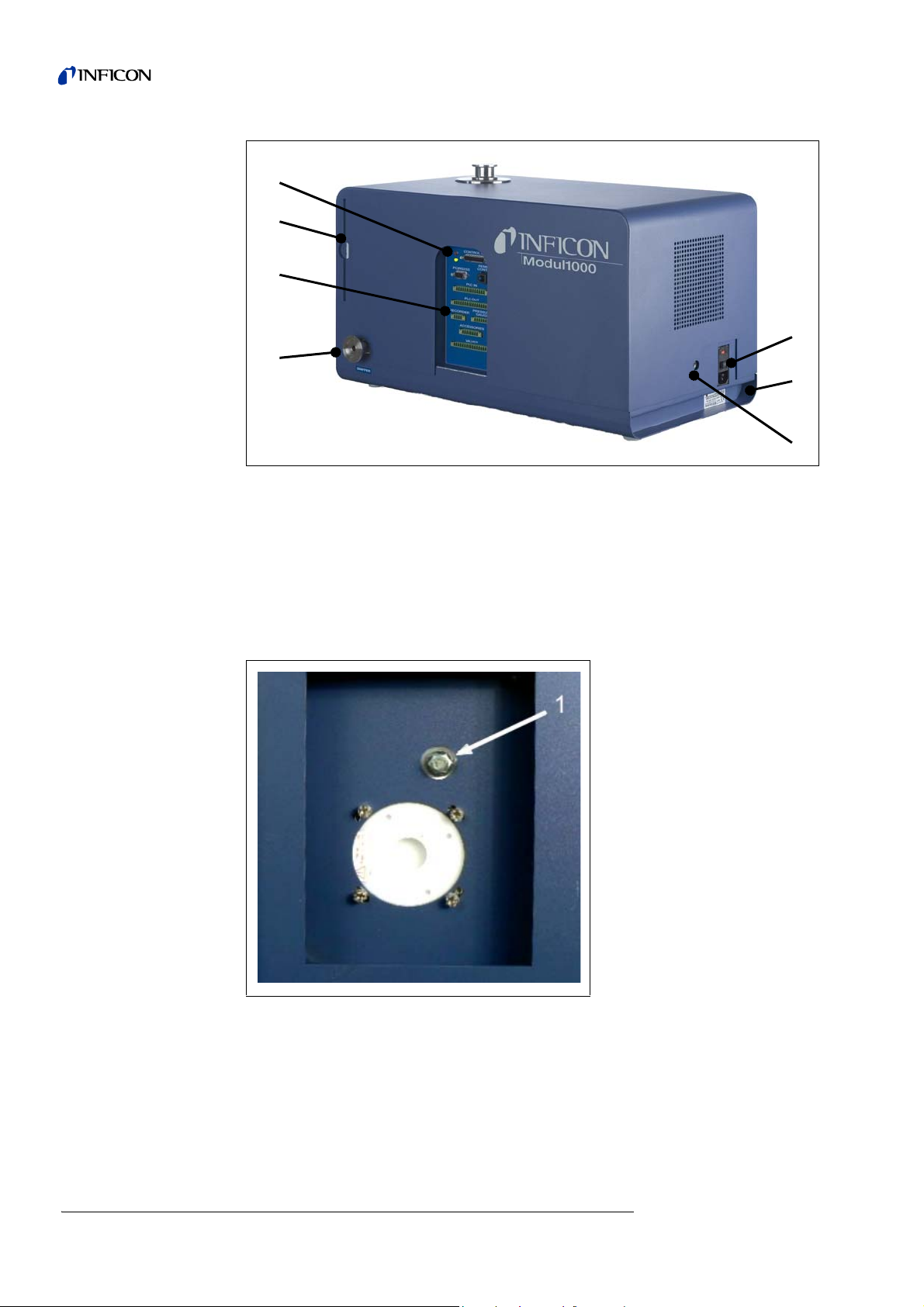
Fig. 3-2 Right side view and back view
9
10
11
6
5
4
3
Item Description Item Description
3 Openings for unlocking 9 Mains socket with main switch and
the cover Mains fuses
4 Recess handles 10 Connection DN25 KF for
5 Status LED Fore-vacuum pump or sniffer line
6 air filter 11 Electrical interfaces
Fig. 3-3 Cut-out in the bottom side of Modul1000
Item Description
3-2 Description of equipment
1 Connection for the fore-vacuum pump (screwed flange)
jinb80e1-h Operating Manual(1011)
Page 21
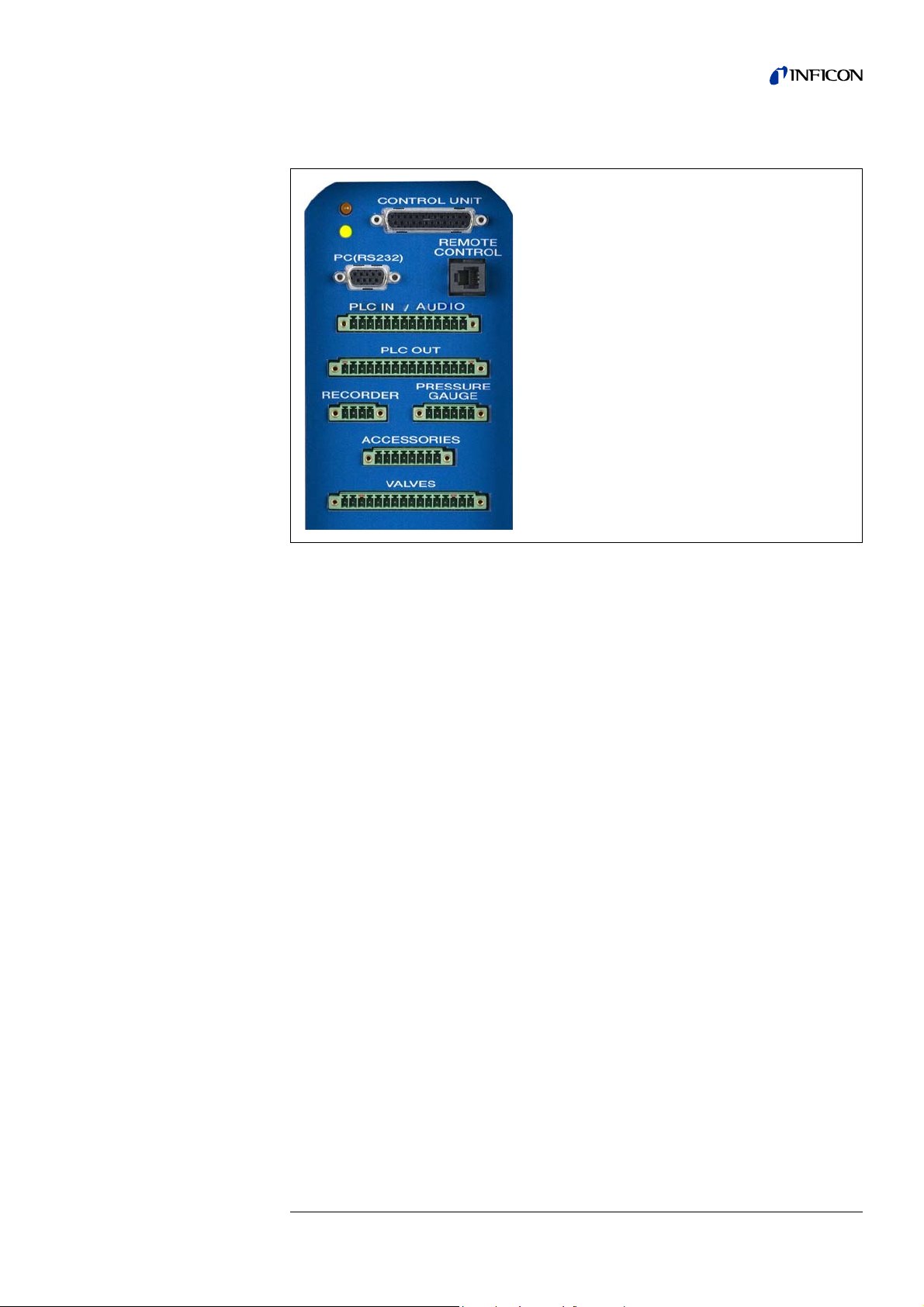
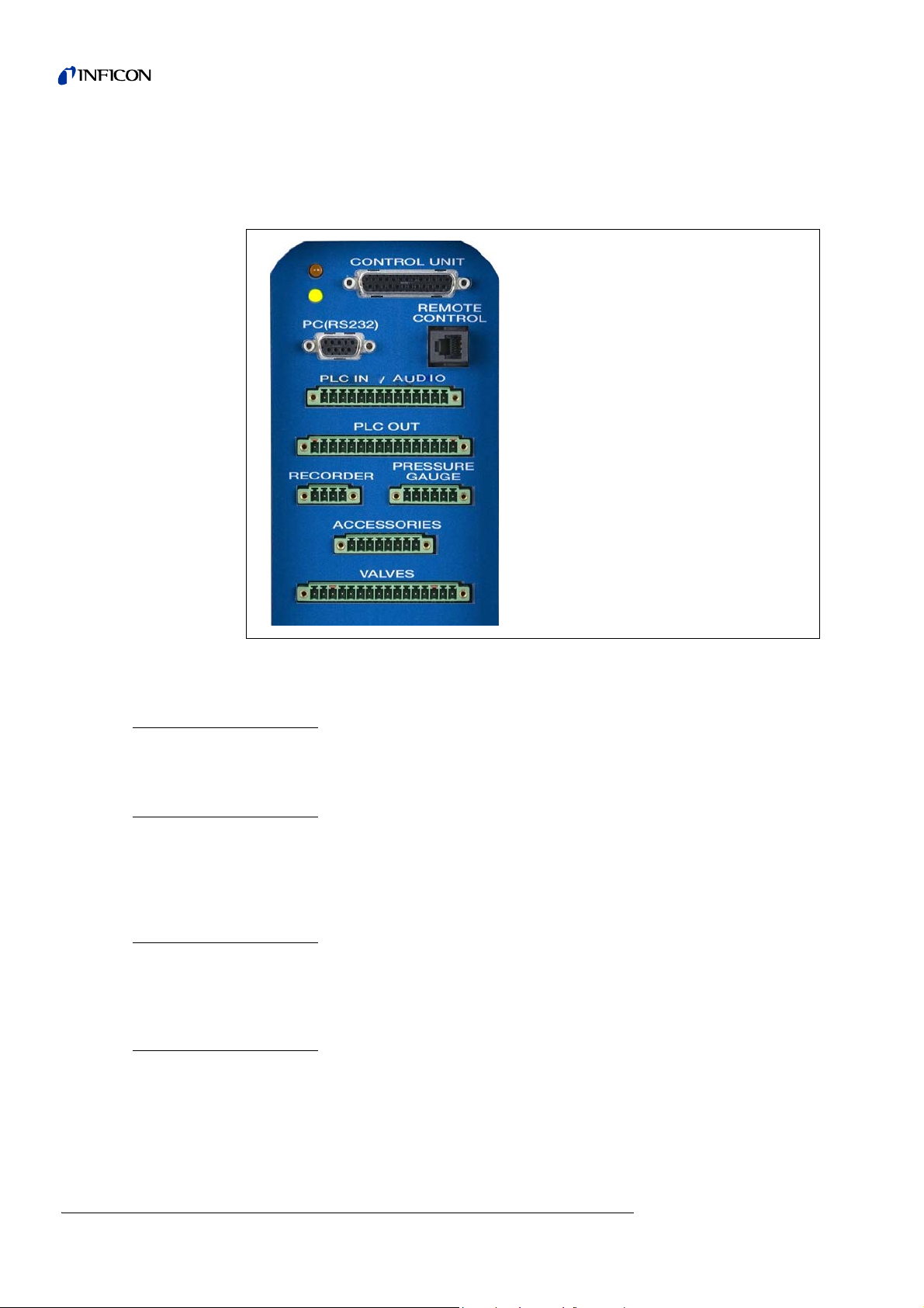
3.2 Interfaces
Connectors:
LED yellow, LED green, CONTROL UNIT
(PC) RS232, REMOTE CONTROL
PLC IN / AUDIO
PLC OUT
RECORDER, PRESSURE GAUGE
ACCESSORIES
VALVES,
Fig. 3-4
The two 16-pin plug connectors PLC OUT and VALVES are keyed so they cannot be
interchanged. For the PLC OUT, coding tongues are inserted on the pins 1 and 16,
for the VALVES connector, the tongues are on the pins 3 and 14.
3.3 Operating options
The Modul1000 can be operated via the control unit for desktop operation or the
control panel for the installation in a switch cabinet.
The Modul1000 provides an extensive software menu which serve s for operation and
configuration (refer to 6.11 Menu structure). This control unit offers access to the
menu structure.
The control unit can optionally be connected to the Modul1000 via 1 m or 5 m long
connecting cables.
The control unit is for configuring and controlling the Modul1000 individually and
parameters as well as measured values can be read out.
jinb80e1-h Operating Manual(1011)
Description of equipment 3-3
Page 22
3.3.1 Desktop operation
1
6
5
4
3
2
7
8
9
10
11
12
13
14
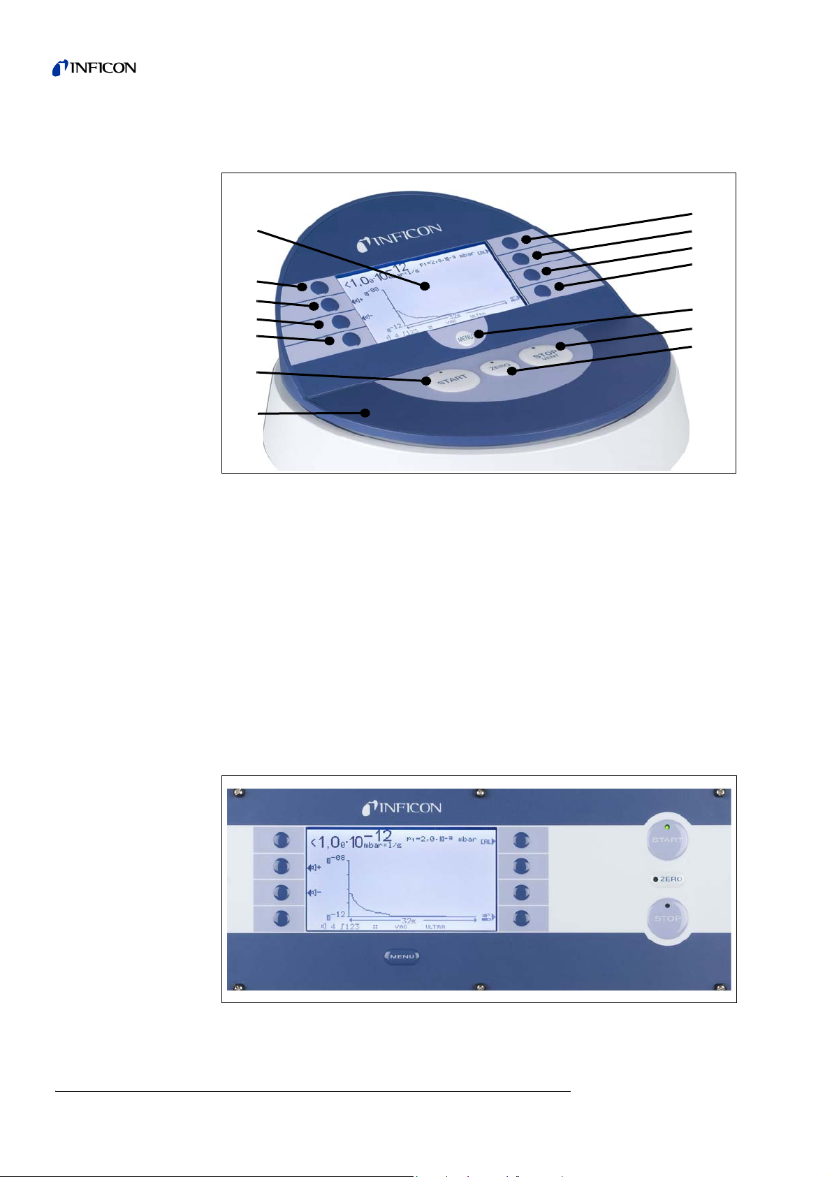
The control unit can be placed on even desktops and does not slip.
Fig. 3-5 Control Unit for Desktop Operation
Item Description Item Description
1 LCD display 8 Soft Key no. 5
2 Soft Key no. 1 9 Soft Key no. 6
3 Soft Key no. 2 10 Soft Key no. 7
4 Soft Key no. 3 11 Soft Key no. 8
5 Soft Key no. 4 12 Menu button
6 START button with LED 12 STOP / Vent button with LED
7 Control Unit 14 ZERO button with LED
3.3.2 Installation in switch cabinet
The control panel (Control unit as mounting version) is intended to be integrated in
the front of a 19’' rack system.
3-4 Description of equipment
Fig. 3-6 Control panel for the installation in a switch cabinet
jinb80e1-h Operating Manual(1011)
Page 23
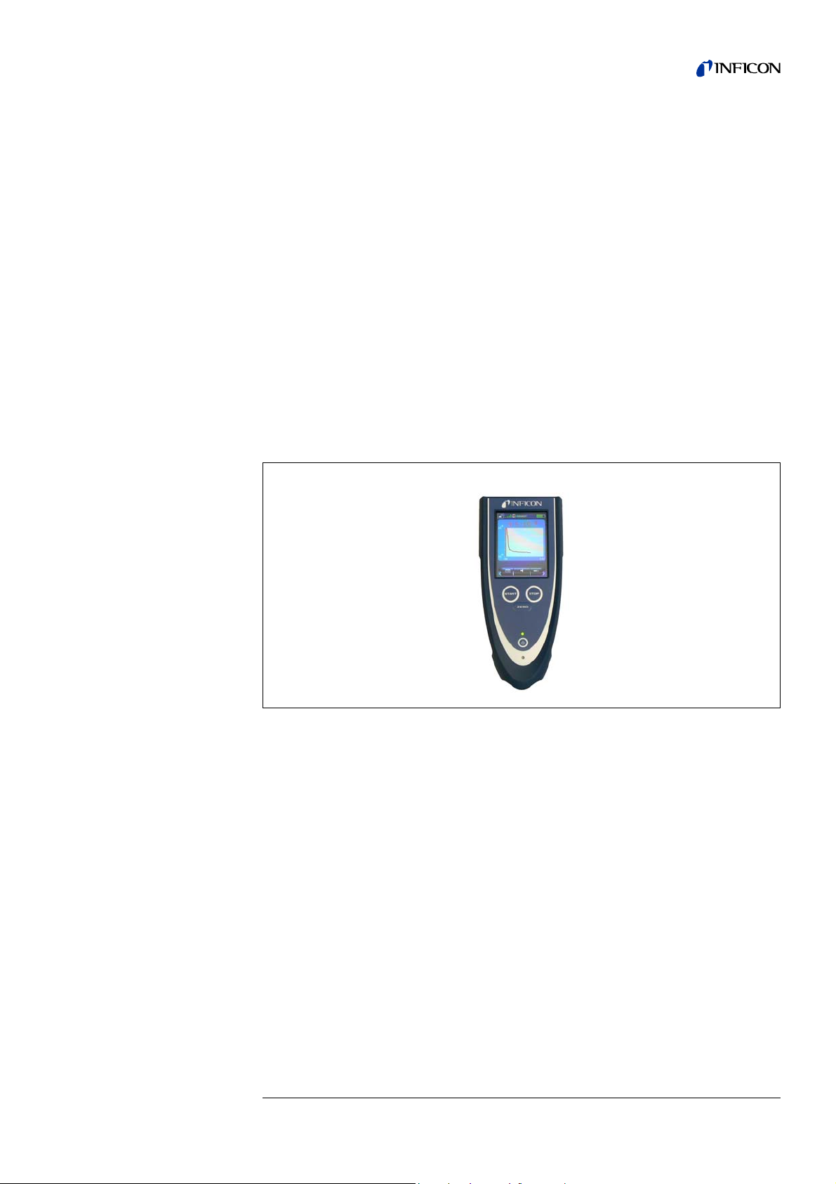
3.3.3 Remote control RC1000
The wireless remote control RC1000 allows the operation of the Modul1000 from a
distance of maximum 100 m. The remote control can serve for controlling the functions START, STOP/VENT (STOP/Vent), ZERO (Background). It shows the measured leak rate on the display as bar graph, a s digits, or as diagram (refer to Technical
Manual of RC1000).
The measured values can be stored in the internal memory of the RC1000 for a
recorded period of maximum 24 hours. Then the data can easily be transferred to a
USB stick.
An internal trigger can be set to provide a warning if the limit leak rates are exceeded.
An optical warning is shown on the display and an acoustic warning signal is
sounded on the integrated loudspeaker or the connected headphones.
The RC1000 remote control is housed in a robust housing to ena ble ergonomic working. Magnets on the underside of the unit enab le it to be attached to horizontal or vertical metal surfaces.
With the remote control RC1000, the leak test device Modul1000 ca n also be controlled via a 28 m long cable.
Fig. 3-7 RC1000 wireless remote control
jinb80e1-h Operating Manual(1011)
Description of equipment 3-5
Page 24

3.4 Scope of delivery
• Leak test device for helium and hydrogen, Modul1000
• Power cords EU, US
• Set of spare fuses
• Folder with documents
• Tools for opening the cover 8 mm Allen-key
• Metering orifice DN25, 2 mm
3.5 Accessories
Accessories Cat. No. / Ref. No.
Sniffer line SL200 140 05
Test chamber TC1000 551-005
Set of male connectors for Interfaces 551-110
Control unit (desktop version) 551-100
Control unit (mounting version 19 inches) 551-101
Connecting cable for control unit, 1 m 551-103
Connecting cable for control unit, 5 m 551-102
Remote control 20099022
- Cable for remote control (required) 20099027
- Extension cable 14090
RC1000 remote control
- RC1000WL wireless 551-015
- RC1000WL - cable version 551-010
- Extension cable, 8 m, for RC1000C 14022
3.5.1 Sniffer line SL200
The Modul1000, in the version as vacuum or sniffer leak detector needs the sniffer
line SL200 to be able to work in sniffer mode.
3.5.2 Test chamber TC1000
The vacuum chamber TC1000 serves for integrated testing of helium-filled parts. The
test procedure can be configured individually in the software m enu of Modul1000 and
runs automatically after the chamber has bee n clos ed .
3-6 Description of equipment
jinb80e1-h Operating Manual(1011)
Page 25

3.5.3 Set of male connectors for Interfaces
The connector kit includes the following plugs:
PLC IN / AUDIO,
PLC OUT,
RECORDER,
PRESSURE GAUGE,
VALVES,
ACCESSORIES
jinb80e1-h Operating Manual(1011)
Description of equipment 3-7
Page 26

3-8 Description of equipment
jinb80e1-h Operating Manual(1011)
Page 27
4 Installation
Warning
Caution
Back injury through heavy loads.
Two people should carry the Modul1000 or use a lifting device.
4.1 Mechanical Installation
The Modul1000 can be mounted on and below desktop workplaces. The leak test
device may only be operated on horizontal surfaces. During the installation, make
sure that the Modul1000 gets enough fresh air, especially the air inlet and outlet
openings on the front and the back side have to be free. The maximum permissible
ambient temperature of the Modul1000 may not be exceeded during operation!
4.2 Electrical installation
4.2.1 Mains socket
The device is connected to the power system via th e deliv er ed po we r ca ble . Please
find the respective socket on the back of the device. (refer to Fig. 3-2/9).
Place the device in a way that you can always reach the power plug.
jinb80e1-h Operating Manual(1012)
Installation 4-1
Page 28
4.2.2 Electrical interfaces
All electrical interfaces of the Modul1000 are clearly visible arranged in a connecting
area on the right side of the device (refer to Fig. 3-2).
Connectors:
LED yellow, LED green, CONTROL UNIT
(PC) RS232, REMOTE CONTROL
PLC IN / AUDIO
PLC OUT
RECORDER, PRESSURE GAUGE
ACCESSORIES
VALVES,
Fig. 4-1 Electrical interfaces
Valves
The connection VALVES is for controlling external valves.
PLC Inputs and outputs
To connect the control inputs and outputs (PLC IN /PLC OUT) use the connector kit.
The connectors are not included in the scope of delivery, b ut are available as accessories (see 3.5, Set of male connectors for Interfaces, Part-No. 551-110)
Graphical control unit
A graphical control unit is connected to CONTROL UNIT via an appropriate connecting cable.
Hand set
The remote control is connected to REMOTE CONTROL.
4-2 Installation
jinb80e1-h Operating Manual(1012)
Page 29
Sniffer line SL200 or test chamber
STO P
Danger
TC1000 (ACCESSORIES)
The connection ACCESSORIES serves for connecting the sniffer line SL200 or the
test chamber TC1000.
External Pressure gauge
If the Modul1000 is used in Commander mode, an additional pressure gauge has to
be connected to PRESSURE GAUGE. Connect the pressure gauge as follows with
the 8-pin Phoenix-plug "PRESSURE GAUGE".
Pin Assignment
1
2GND
3 Input 1
4 GND to input 1
5 Input 2 (is not supported by the current software)
6 GND to input 2
24V fuse-protected with F3 on the interface board (0.8A, maximum output current,
on this pin together with the pin 1 on connection PLC IN)
Notice: The pressure transmitters to be connected can be supplied via the contacts
1 and 2 of the Modul1000.
If they are supplied by external power supply units, ensure th at the contacts
4 and 6 may only have a maximal potential of ±4V compared to contact 2.
Otherwise it could be damaged.
Notice: The sensor is adjusted correctly, when the zero point and the full-scale
deflection comply with the output characteristic.
Danger of fatal injuries due to electric shock!
First, disconnect the leak test device from the power supply network and then
remove the housing.
The Modul1000 can process measured current or voltage values. When delivered,
the Input 1 is configured for current measurement 4... 20 mA, Input 2 for voltage
measurement 0... 10 V.
To change the configuration of the input of the pressure gauge, the respective jumper
on the interface card in Modul1000 has to be placed onto another position. To do
that, open the device.
The jumpers are located on the interface board and are accessible a fter opening the
cover.
By changing the position of the jumper on the connector XP5, the se tting of the Input
1 can be changed. For a current signal, Pin 1 and Pin 2 of XP5 are connected, for a
voltage signal, connect Pin 2 and 3.
By changing the jumper position on the connector XP4, the setting of the Input 2 will
be changed. However, this input is not supported in the current software.
jinb80e1-h Operating Manual(1012)
Installation 4-3
Page 30
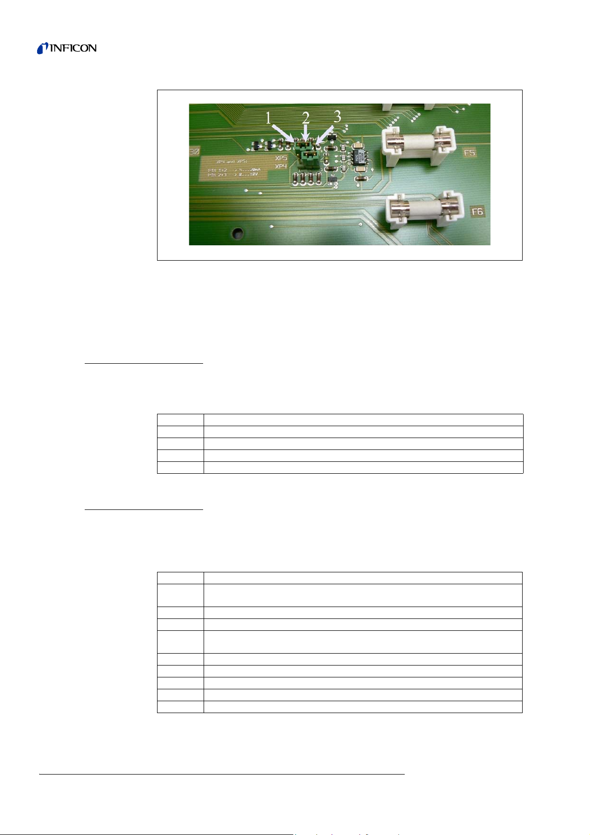
Fig. 4-2 Jumper XP5 and XP4
Item Description Item Description
1Pin 1 3Pin 3
2Pin 2
Recorder Output (analogue)
The two Recorder outputs (analogue outputs) may be used to log the leak rate, the
inlet pressure or the fore-vacuum pressure.
The output voltage is updated every 50 ms.
Pin Assignment
1
2GND
3GND
4
RS232 Interface
The RS232 interface serves for connecting a PC directly to the Modul1000.
The Modul1000 is then directly controlled by the respective instruction sets as
described in the interface description.
Recorder Output 1 (analogue output)
Recorder Output 2 (analogue output)
4-4 Installation
Pin Assignment
1
2TxD
3RxD
4
5 GND RS232
6 not used
7 not used
8 not used
9 not used
24V can tied-in via the jumper XT2, maximum current consumption 0.3 A (Pin 2
and 3 connected). As delivered, 24 V are not tied-in, Pin 1 and 2 connected.
GND 24 V can be tied-in via jumper XT1 (Pin 2 and 3 connected). On delivery,
GND 24 V is not tied-in (Pin 1 and 2 connected).
jinb80e1-h Operating Manual(1012)
Page 31

Using the jumpers XT1 or XT2, Earth or 24 V can be connected to the RS232 inter-
STO P
Danger
face by changing the positions of the jumper (Pin 2 an d 3). On deliver y: XT1 or XT2,
Pin 1 and 2 bridged ≅ "default setting (Standard) RS232“.
Danger of fatal injuries due to electric shock!
First, disconnect the leak test device from the power supply network and then
remove the housing.
The jumpers are located on the interface board and are accessible a fter opening the
cover.
Fig. 4-3 Jumper XT2 and XT1
Item Description
1Pin 1
2Pin 2
3Pin 3
jinb80e1-h Operating Manual(1012)
Installation 4-5
Page 32

4.2.3 Vacuum connections
Fore-vacuum pump
The connection for the required fore-vacuum pump is on the left front side or on the
bottom of the device. Alternatively, the pump connection of the vacuum version of the
Modul1000 can also be on the right side.
1 Unscrew the connecting flange using the jaw-wrench SW13, to modify it and remove
the sealing.
2 Unscrew the locking plug of the connection you want to use
Make sure you save the sealing.
.
3 Screw the locking plug with the sealing into the opening of the removed connection
flange.
4 Screw in the connecting flange with the sealing.
Notice: For the sniffer version of the Modul1000, only the pump connections on the
left side or on the bottom side can be used.
The used fore-vacuum pump must meet the following specifications:
• The connecting hose should have a minimal diameter of 15 mm.
• The fore-vacuum pump should provide a pumping speed of >2 m³/h
• and a possible ultimate pressure of <1x10
-2
mbar.
If the fore-vacuum pump is equipped with a solenoid gas ballast valve or purge gas
valve, it can be controlled via the valve output V22 of the Modul1000.
Test sample/Test Equipment
The test sample or the test equipment are connected using the DN25 KF inlet flange
on the top of the Modul1000.
To be able to measure with the leak test device also in case of pressures higher th an
0.4 mbar, the metering orifice, which is in the scope of delivery, can be mounted
before the inlet of the leak test device. If the metering orifice is installed in the suction
line of the leak test device, the maximum inlet pressure will be 3 mbar.
Because the pumping speed is greatly reduced when a metering orifice is inserted,
it will be reasonable to use a partial flow pump for evacuation.
To achieve short signal response times of the Modul1000, the orifice should be
mounted as close as possible to test sample, test equipment.
In Modul1000b, the metering orifice has already been in stalled and can also measure
until 3 mbar.
Notice: The maximum permissible load vertically on the flange is 400 N.
4-6 Installation
jinb80e1-h Operating Manual(1012)
Page 33

Ventilation
Sniffer line
Fig. 4-4 Installation of metering orifice
Usually the parts under test are vented with ambient air after the test has been
finished. If it is required, the parts can be vented with an different gas type (i. e. fresh
air, dry air, nitrogen, …) at a pressure of max. 1050 mbar. In these cases, the gas
supply has to be connected to flood connection (8 mm hose connection) on the left
side of the device. The gas pressure on the flood connection may not exceed
1100 mbar (absolute).
It is also possible to connect an additional external ventilating valve to the valve
output V21.
The connection for the sniffer line exists only for the sniffer version of the Modul 1000
(catalogue number 550-310). This connection is for the optional sniffer line SL200.
The SL200 is connected to the power system via the connector socket ACCESSORIES.
jinb80e1-h Operating Manual(1012)
Installation 4-7
Page 34

5 Working Modes
There are the following vacuum modes:
• Vacuum,
• Commander,
• Auto Leak Test.
In this operating mode, it is possible to use a partial flow pump.
The sniffer version of the Modul1000 also provides the operating mode:
•Sniff.
5.1 Vacuum
In standard Vacuum mode, the Modul1000 id operated as „Stand Alone“ leak detector.
The unit under test or the vacuum chamber ar e only evacuated via the inlet flang e of
the leak detector. The pumping speed on the inlet of the leak detector depends on
the used fore-vacuum pump and on the conductivity ratios of the device.
If the pressure is lower than 0.4 mbar, the device will switch over to the Measuring
mode and display the measured leak rate.
When measuring, the pumping speed at the inlet is 2.5 l/s.
The effective pumping speed at your chamber is dependent o n the integration of the
Modul1000.
5-1 Working Modes
jinb80e1-h Operating Manual(1012)
Page 35

5.2 Partial Flow Mode
To increase the effective pumping speed on the vacuum chamber or the test sample,
an external partial flow valve can be connected to the valve output V20. The
increased pumping speed accelerates the evacuation processes and the signal
response time of the Modul1000.
Depending on the settings, the partial flow pump can optionally be added via an
external partial flow valve only for evacua tio n or fo r eva cu a tio n du rin g the me as ur ement.
If the partial flow pump is also added during the measurement, the pumping speed
of the partial flow pump for helium has to be considered. In this case, adjust the
machine factor as required (refer to chapter 6.9). Furthermore, an external calib ration
is recommended (refer to chapter 6.6).
For fast venting of the device, the connection of an additional external vent valve V21
will be possible.
Fig. 5-1 Partial flow mode
Item Description Item Description
V20 Partial flow valve V21 Ventilating valve
jinb80e1-h Operating Manual(1012)
Working Modes 5-2
Page 36

5.3 Auto Leak Test
In Auto Leak Test mode, parts prefilled with helium can be tested integrated in a
vacuum chamber. In this case, the Modul1000 does all control functions completely
for the test run.
The test run is divided into the following steps:
Evacuation of the vacuum chamber,
Measurement of leak rate and
then venting of the vacuum chamber.
At the end of the test, the device displays „PASS“ on the control panel provided that
the leak rate did not exceed the set trigger value during the measuring time. If the
trigger value is exceeded, the device will display the message „FAIL“.
Optionally, the test can also be carried out in Partial Flow mode.
After pressing the START button, the whole test runs automatically. When using the
optional test chamber TC1000, the test cycle starts automatically as soon as the
chamber cover is closed.
5.3.1 Auto Leak Test Settings
Select the Auto Leak Test mode via the control panel or the RS232 interface.
The test run can be adapted to your special application of the leak detector. The
corresponding settings can be entered via the control panel or the RS232 interface
(refer to Interface Description).
Measuring time
The measuring time starts as soon as the Modul1000 switches over from the evacuation phase to the Measuring mode. The possible time settings range from 1 second
to 30 minutes.
At the end of the measuring time, the measured value is displayed.
Trigger level
If the set trigger level 1 is exceeded at the end of the measurement cycle, the
Modul1000 indicates the message „FAIL“ and hence, it signals a leaky test sample.
Part number
In the software menu, the parts counter can be enabled, which assigns a number to
the individual measurement cycles. On the menu screen "Test report", the last 12
measured results can be displayed with date and test result.
Series error message
The menu provides a setting, with which a series error message can be displayed
when a certain number of consecutive errors with the "FAIL" result occur. The set
number of consecutive measuremen ts after which the Mo dul1000 disp lays a series
error message can vary between 2 and 9. If not required, it can be disabled.
jinb80e1-h Operating Manual(1012)
5-3 Working Modes
Page 37

To ensure that such an abundance of consecutive „FAIL“- messages is not caused
by the helium background of the test equipment, a reference measurement is recommended.
Reference measurement
If the ambient helium emitted by the chamber is significant in relation to the target
leak rate, it is possible to perform a reference measurement.
In the software menu, it is possible to enable a reference measurement. If it is
enabled, it can be called via the Measurement screen.
During the reference measurement, the Modul1000 determines the internal helium
background of the test equipment and then it deducts this values from the values of
following measuring cycles.
The reduce the background of the test equipment in case of a reference measurement, the vacuum system of the device is evacuated and vented for three times.
5.4 Commander mode
If the Modul1000 is integrated in a leak detector system, in Commander mode, it can
control the whole test in the integrated chamber. All necessary valves for filling the
test sample with helium as well as the necessary pressure gauge can directly be
connected to the Modul1000. The test run can only includ e a device for helium recovery.
Optionally, the test can also be carried out in Partial Flow mode to accelerate the leak
detection.
jinb80e1-h Operating Manual(1012)
Working Modes 5-4
Page 38

5.4.1 Design of a leak detector system
Design of a leak detector system with Modul1000- - -Commander function is mainly
the same as that of the conventional integrated leak test system.
The vacuum chamber is evacuated by the Modul1000, optionally also in partial flow
mode (Fig. 5-1 Partial flow mode). The test sample in the vacuum chamber is
connected to the helium filling station through the chamber walls and is filled with
helium after the chamber has been evacuated.
Due to the difference between the helium pressure in the test sample and the
vacuum in the vacuum chamber, the helium of a leaky part flows out of the leak into
the vacuum chamber and into the leak test device whe re it can be me asured as ga s
leak.
5-5 Working Modes
Fig. 5-2 Leak detector system
Item Description Item Description
V30 Valve evacuation (test sample) 1 Vacuum chamber
V31 Flood valve (test sample) 2 Test sample
V32 Valve for helium recovery 3 Pressure gauge
V33 Filling valve (test sample) 4 Vacuum valve (test sample)
V34
Emergency valve (de-energized
open)
5 Fore-p ump (Modul1000)
jinb80e1-h Operating Manual(1012)
Page 39

Helium filling station
The helium filling station consists of a vacuum pump, the valves V30- V34, a pressure gauge and the helium supply unit.
Valves V30, V31, V32, V33, V34
The test run of the Commander software includes the control of all valve s necessary
for the helium filling procedure of the test sample. The valves are controlled via the
„VALVES“ connection.
Notice: We recommend using pressure activated valves.
Pressure gauge
The test sample is filled with helium and the gross leak test are pressure controlled
and therefore, they need a pressure gauge which has a measuring range of <
50 mbar reaching to the maximum filling pressure of the test sample. The characteristics and the measuring range of the used measuring point can be set on the
Modul1000. The pressure gauge is connected to the „PRESSURE GAUGE“ terminal
on the right side of the device.
Vacuum pump
The vacuum pump evacuates the test sample before it is filled with helium to remove
the air from the part as well as possible. We recommend using a pump with a final
pressure of < 50 mbar.
5.4.2 Test sequence of events
1 The test sample is in the vacuum chamber which is connected to the inlet of
Modul1000. The unit under test is in the vacuum chamber which is connected to the
inlet of Modul1000.
2 After the START signal, the Modul1000 starts evacuating the vacuum chamber. If a
partial flow pump is connected with Modul1000, the partial flow valve V20 (Fig. 5-1)
will be actuated and the test run is accordingly supported by the partial flow pump.
3 Before the actual helium test is executed, a gross leak test is carries out, to detect
gross leaks in the test sample or in the leak detector. When a chamber pressure of
100 mbar is reached, it will be checked, whether the pressure of the test sample has
dropped and is lower than the set pressure p_A_ for the gr oss leak test. If this is the
case, the measuring cycle will be interrupted indicating the error message 91.
4 If the system passes the gross leak test, valve V30 will be opened and the test
sample will be evacuated. If the systems passes the gross leak test, the valve V30
will open and the test sample will be evacuated. Otherwise, the measuring cycle will
be interrupted indicating the error messa g e 92 .
5 If the chamber pressure drops within the set time t_F_Readiness_for_measurement
down to the change-over pressure, the device will switch over to Measuring mode.
This change-over pressure can be set in the following menu:
Main menu --> Settings --> Monitoring --> Pressure limits for vacuum areas"
between 0.2 mbar and 0.4 mbar.
Depending on the settings in "Background suppression", an automatic background
jinb80e1-h Operating Manual(1012)
subtraction will be carried out, if necessary:
Working Modes 5-6
Page 40

• When "OFF" is set: no zeroing is carried out
• When "ON" is set: zeroing is carried out after the t_B_zeroing delay time
• When "STABLE" is set: zeroing will be carried out within the t_B_zero delay time
provided that the leak rate signal is stable enough to indicate a leak of the set
trigger level 1. If this condition is not complied with within the t_B_zero delay time,
the measuring cycle will be stopped and error message 98 will be generated.
If the chamber pressure is not low enough within the set time
t_F_Readiness_for_measurement to switch over to the measuring mode, the test
procedure will be interrupted indicating the error message 94.
6 After the evacuation of the test sample, the valve V33 is opened and the filling
process of the part with helium can start. If the pressure in the test sample reaches
the set filing pressure p_C_Filling_pressure within the set time t_C_Filling_time, the
valve V33 will be closed again and the filling process will be completed. If the filling
pressure is not reached on time, the measuring cycle will be interrupted indicating
the error message 93.
7 The actual leak test is now started. The measured leak rate is displayed when the
set time t_G_ Measuring_time has expired. If the pressure of the test sample drops
below the pressure p_E_Pressure_drop_threshold during the leak test due to a leak
in the system, the measuring cycle will be interrupted indicating the error message
99.
8 At the end of the measuring time, the valve V32 is opened.
Helium is returned from the test sample to the helium filling facility until the pressure
in the sample has reached the depressurizing pressure
p_D_Depressurizing_pressure. After that, V32 is closed again.
If this does not happen within the set time t_D_Depressurizing _time, the measuring
cycle will be interrupted indicating the error message 95.
9 To remove the residual helium from the test sample, valve V30 opens and the test
sample is evacuated by the pump 4 until the pressure p_B_ Evacuation_pressure is
reached.
This has to be done within the set time t_A_Evacuating _time, othe rwise the measuring cycle will be interrupted indicating the error message 96.
10 Valve V30 will be closed. The unit under test is vented to reach atmospheric pressure
via valve V31.
If the set filling pressure for the test sample p_A_Gross_leak_test is not reached
within the time t_E_Ventilation_time, the measuring cycle will be interrupted indicating the error message 97.
11 After that, the vacuum chamber is ventilated by the Modul1000 (and the external
flood valve V21 (Fig. 5-1), if connected) to reach the atmospheric pressure.
jinb80e1-h Operating Manual(1012)
5-7 Working Modes
Page 41

5.5 Sniff mode tips
The Modul1000 Sniffer version can be used as vacuum leak detector or as sniffer
leak detector.
To use it as sniffer leak detector, the optimized sniffer line SL200 has to be
connected to „Sniff“ on the right side of the Modul1000. In Measuring mode, the
module draws a constant gas flow through the sniffer line. The helium in the gas flow
is indicated as leak rate.
In Sniff mode, the detection limit is restricted to 1×10
pheric helium background.
The gas flow rate though the sniffer line is approximately 25 sccm.
It is electrically connected by the "ACCESSORIES“ connector.
The operating mode must be set to "Sniff mode".
In "SNIFF"-mode, the red LED on the sniffer handle indicates a bad test sample and
the green LED indicates a good test sample.
The active push-button on the sniffer handle of the sniffer line can be used for switch-
ing on the external background suppression. If the push-button is pressed for a
longer time (3 seconds), the external background suppression is switched off again.
-7
mbarl/s due to the high atmos-
jinb80e1-h Operating Manual(1012)
Working Modes 5-8
Page 42

6 Operation
6.1 Switching ON
Install the device as described in the Installation chapter. Connect the power cable.
Switch the device ON. The mains switch and the connection for the power cab le a re
at the back of the device.
After the mains switch has been actuated the devices runs up automatically.
In run-up mode (≤ 3 Min.) the following items appear on the display:
• Speed of the turbo-molecular pump
• Fore-vacuum pressure
• State of emission
• Active filament
• A bar graph which shows the run-up progress
After the run-up has been completed, the Modul1000 is in „Standby“ mode.
6.2 Status LED
The LEDs show the operating mode of the device:
Operating mode: LED, green LED, yellow
Run-up Flashes Flashes
Standby/Vent On Off
Evacuate On Flashes slowly
Measuring On On
Calibrating Flashes synchronously Flashes synchronously
Error / Warnings /
Maintenance messages
Off Flashes fast
6-1 Operation
jinb80e1-h Operating Manual(1012)
Page 43

6.3 Control
Control Panel
Hand set
The Modul1000 can be controlled via the control unit, the remote control, the PLC
inputs or via the RS232-interface. These options can be selected in the menu item
„Control location“.
(refer to: Main menu → Settings → Interfaces → Control location)
The optional control unit can be used for programming and controlling of all device
functions and information can be read out.
The functions and the menu structures of the control unit for desktop operation (refer
to chapt. 3.3.1) and the control panel for the rack installation (refer to chapt. 3.3.2)
are the same.
The optional remote control (refer to chapt. 3.3.3) includes the main functions Start,
Stop, Vent, and Zero. Additionally the volume can be controlled.
If „LOCK“ is displayed, the control of the Modul1000 via the remote control was disabled in the menu item „Control location".
RS232 Interface
The RS232 interface serves for connecting a PC directly to the Modul1000.
Then, the control commands will be sent by appropriate interface commands to the
device, as described in the interface description.
PLC Inputs and outputs
The most important control commands can also be sent to the Modul1000 via a PLC.
The functions of the inputs and outputs can be configured.
jinb80e1-h Operating Manual(1012)
Operation 6-2
Page 44

6.4 Control commands
The following control commands can optionally be sent to the Modul1000 to the
control unit / remote control via the PLC control inputs or via the RS232 interface.
START
If the control unit is connected, the LED in the START-button will flash during the
evacuation process.
During the measurement, it will light up continuously.
If the START button on the control unit is pressed during the measurement, the maximum leak rate display will be enabled (Hold function). This is the highest leak rate
which has been measured since the start.
If the START button is repeatedly pressed, this Hold function will be initialized.
The LED in the button indicates the status:
LED flashes: Evacuate
LED ON: Measuring operation:
By pressing the START button, the Modul1000 starts to evacuate the connected test
sample.
If the pressure on the inlet of the leak test device reaches < 0.4 mbar , the Modul1000
will automatically switch over to the Measuring mode.
This pressure limit can be set in the following menu:
Settings
.
→
Monitoring → Pressure limit for the vacuum area
STOP / VENT
ZERO
The STOP command stops the measurement and the leak test device switches over
to the Standby mode.
If you press the STOP button briefly, the measurements are interrupted.
If the button is pressed longer, the inlet is vented according to the conditions defined
in the menu "Vent delay".
LED ON: Inlet vented
Pressing the ZERO button activates the background suppression. To disable the
background suppression again, it will be enough to keep the ZERO push button
pressed for about 3 seconds.
The status of the ZERO-button is indicated by the LED:
LED ON: ZERO enabled
Notice: The ZERO function should be started only when the background signal is
stable. In the I-ZERO setting, the ZERO function can be used only then
when the dropping background signal beco mes constant.
jinb80e1-h Operating Manual(1012)
6-3 Operation
Page 45

Menu
Display-buttons
Fig. 6-3 Zero function (background suppression)
Item Description Item Description
1 Leak rate signal without ZERO 5 Leak 5E-10 mbarl/s with ZERO
2 ZERO is enabled 6 Floating Zero adjustment
3 Suppression of two decades 7 No Zero-adjustment
4 Leak 5E-10 mbarl/s without ZERO
Pressing the MENU button displays the selection menu.
The functions of the eight buttons on the left or on the right of the display depend on
the selected menu. Please find the description of relating functions on the display.
Numerical Entries
If you have opened a menu screen for numerical entries please proceed as follows:
• If you do not want to change any digits, press key „Cancel“ to abort.
• The digit that can be changed is displayed shaded. Use the keys No. 8 and No. 4
and go to the position to be changed.
• To change a digit to a specific number press the corresponding pair of numbers.
A sub-menu opens and the desired number can be se lect ed .
The sub-menu closes automatically and the next whole number will be displayed
with inverted colours and can be changed.
Having reached the last digit all corrections have to be confirmed by OK.
jinb80e1-h Operating Manual(1012)
Operation 6-4
Page 46

Fig. 6-4 Examples for a numeric input of Trigger Level 1
To change the trigger level from 1.0x10⁻⁹mbarl/s to 3x10⁻⁹mbarl/s please press 2/3
(button No. 3). A sub-menu is opened, in which the desired value 3 (button 4) can be
selected.
6-5 Operation
jinb80e1-h Operating Manual(1012)
Page 47

6.5 Display
Run up
Status line
The display shows measuring values, operating modes, device parameters and their
values, as well as functions of the eight buttons on the left and o n the right side of the
display.
After it has been switched on, the Modul1000 displays so me sta tu s info rm a tion .
The following details on the device are shown in the status line at the bottom of the
display after the Modul1000 has run up.
Standby
Evacuation
Display
symbols
S1, 2, 3 Trigger Level 1, 2, 3
• • Detected mass
VAC Operating Mode
ZERO ZERO Indicates if ZERO-function is active.
COR Corrected leak rate
Meaning Explanation
Sound volume Refer to chapter Volume for the audible signal
If the trigger values are exceeded these signs are
inverted. (White on black background.)
The number of dots stands for the mass number
(4 dots = helium, 2 dots = hydrogen).
Warning triangle Refer to chapter 4.4.2
VAC, SNIFF, COMMAND or AUTO LEAK TEST
stand for the selected operating mode.
It shows if the leak rate is corrected with the
machines factor.
After the run-up has been completed, the Modul10 00 a utomatica lly switches over to
Standby mode and is ready for measurement.
Pressing the START button causes the Modul1000 to evacuate the inlet.
The evacuation time depends on the volume connected the M odul1000 and the forevacuum pump or the partial flow pump.
jinb80e1-h Operating Manual(1012)
Operation 6-6
Page 48

Measuring
p
2
V2
MS
V6
V7
p
1
V1
V4
V22
Fig. 6-5 Evacuate
When the pressure on the inlet of the Modul1000 drops below the set lo wer pressure
limit, the device will change over to measuring mode.
6-7 Operation
Fig. 6-6 Measuring
jinb80e1-h Operating Manual(1012)
Page 49

Display of measured values
In Measuring mode, two ways of displaying the measured values are available.
• Numeric display with big sized numbers as bar graph.
Fig. 6-7
• Graphic display as function of the measuring time
Fig. 6-8
You can switch over between the numeric display and the graphic display using the
button No. 8. It is labelled with the symbols for numeric and graphic display.
jinb80e1-h Operating Manual(1012)
Operation 6-8
Page 50

6.6 Calibration in Vacuum mode
The Modul1000 can be calibrated in two different ways: For each calibration, calibrate the mass spectrometer to achieve maximum sensitivity (Autotune).
Depending on the applied test leak, internal or external calibration is required.
No matter, which control location is used, the calibration can be started in the following ways:
Set control location
Internal manual LOCAL, RS232 ASCII
Internal automatic LOCAL, RS232 ASCII, RS232 BINARY, PLC
External manual LOCAL, RS232 ASCII, RS232 BINARY, PLC
External automatic LOCAL, RS232 ASCII
For the internal calibration, the test leak integrated in Modul1000 is used.
For the external calibration, a separate test leak is required. External calibrations
have the advantage that they can be carried out under boundary conditions (pressure, measuring time) similar or equal to the later measurements.
If a control unit is connected to the Modul1000, the LEDs in the buttons START,
STOP / VENT and ZERO light up during the calibration.
Notice: To get an optimized calibration the machine has to warm up for at least 20
minutes before use.
Internal Calibration
If a partial flow pump is used in measuring mode, set the correct machine factor
before the 1st calibration.
The internal calibration is not done in partial flow mode, not even if it is set to „Partial
flow in measuring mode“. It will be corrected via the set machine factor.
Automatic Internal Calibration
After starting the calibration, the whole calibration procedure runs automatically.
In this case, the signal transient time of the test leak (CAL-transient time) is used
which can be set in the menu. Before, it must be adjusted to th e vo lum e at the inle t.
The CAL-transient time increases depending on the volume enclosed at the inlet.
Manual Internal Calibration
After starting the Calibration, the Modul1000 opens the internal test leak and evacuates the inlet. The signal transient time stretches depending on the connected
volume stretches.
Therefore the user has to confirm that the signal has become constant.
6-9 Operation
jinb80e1-h Operating Manual(1012)
Page 51

External Calibration
The external calibration has the advantage that it considers the application-specific
measuring conditions. The external calibration leak can b e connected to the vacuu m
chamber.
Calibration leaks with solenoid valves can be connected to the terminal VALVES at
the back of the device. Then, the Modul1000 automatically controls the valve.
Before the calibration, enter the corresponding value of the calibration leak which
shall be used for calibrating the Modul1000 in the settings of the Modul1000. This
can be done via the optional control unit or the RS232 interface.
The external calibration in the Partial Flow mode is carried out with the setting „Fore
and partial flow pump“ in the item „Measure mode". (see chapt. 6.12.6.1)
Automatic External Calibration
The automatic external calibration requires a calibration leak with solenoid valve.
It is electrically connected via the VALVES connector.
After starting the automatic external calibration, the Modul1000 runs through the
complete calibration sequence.
In this case, the signal transient time of the test leak (CAL-transient time) is used
which can be set in the menu. Before, it must be adjusted to the volume at the inlet.
The CAL-transient time increases depending on the volume enclosed at the inlet.
Manual external Calibration
In case of the manual external calibration, the test leak has to be opened and close d
manually.
Also acknowledge the steady-state test leak signal manually.
The control unit or the control panel guides the user through the calibration routine
via the display.
6.7 Calibration in Sniff mode
It only applies for devices with the catalogue No. 550-310 and 550-330.
In Sniff mode, calibration is done in the same way as it is don e for the exter nal man -
ual calibration in Vacuum mode.
With the optional sniffer line connected to the Mo dul1000, it is required to measure
a sniffer test leak and a helium background.
Acknowledge the steady-state test leak signal and the steady-state background
value manually.
jinb80e1-h Operating Manual(1012)
Operation 6-10
Page 52

6.8 Calibration in Auto Leak Test
There are four different ways of calibration:
• Internal automatic
• Internal manual
• External automatic
• External manual
For the external calibration, a separa te test leak is required , which is mounted on the
chamber.
In Partial Flow mode, always perform an external calibration.
Sequence of calibration:
1 open the test leak or it opens automatically,
2 evacuate,
3 acknowledge steady-state signal when calibrate manually,
4 autotune (Calibration to maximum sensitivity),
5 vent to atmospheric pressure,
6 evacuate, after the measuring time is over, take the signal with open test leak,
7 vent to atmospheric pressure,:
8 close the test leak, evacuate, after the measuring time take the background signal,
9 vent to atmospheric pressure.
6.9 Calibration in Commander mode
During the calibration, the test gas supply is not enabled.
There are four different ways of calibration:
• Internal automatic
• Internal manual
• External automatic
• External manual
For the external calibration, a separa te test leak is required , which is mounted on the
chamber.
The calibration procedure is the same as it is for the vacuum mode.
6-11 Operation
jinb80e1-h Operating Manual(1012)
Page 53

6.10 Machine factor
The machine factor takes into account that the Modul1000 is used in parallel with a
pumping system.(partial flow method).
Because in such a system configuration only a part of the leak gas flow reaches the
leak test device and is detected, first. the Modul1000 displays measured values on
the basis of the internal calibration which are smaller due to the partial flow ratio.
To avoid this, the machine factor can be saved in the software menu of the
Modul1000. Then, after an internal calibration, the measured leak rates are displayed
multiplied by the machine factor.
The machine factor can be estimated considering the Helium pumping speed of the
Modul1000 and of the external pump .
The measurement of an external test leak on a test sample is more accurate when it
is measured with and without an added external pump. The ratio of both results is the
machine factor.
The machine factor can also be used to correct the leak rate display referred to the
air equivalent.
The machine factor for this correction is: 3.7 x 10
When this setting is used, this status will be displayed by „COR“.
-1
.
jinb80e1-h Operating Manual(1012)
Operation 6-12
Page 54

6.11 Menu structure
Scale linear/logarithmic
Display range auto/manual
View
Mode
Trigger & Alarms
CAL Calibration
Main menu Modul1000
Settings
Time axis
Contrast
Background in standby
Lower display unit
Trigger level 1
Trigger level 2
Trigger level 3
Volume
Units
Alarm delay
Audio alarm type
Internal automatic
Internal manual
External automatic
External manual
Vacuum settings
Zero & Background
Mass
Interface
Others
Purge / Automatic gas ballast
Vent delay
Partial flow
Measuring time
Trigger level 1
Automatic Leak Test Settings
Commander functions Commander pressure threshold
Machine factor
Leak rate internal test leak
Background suppression
zero
Control location
RS232
External pressure gauge
Define PLC outputs
Define PLC inputs
Recorder Recorder output
Output gas ballast
Time/date
Language
Leak rate filter
Part Number
CAL setting time
Maintenance interval
Series Error Messages
Part Number
Reference Measurement
Commander Timing
Background suppression
Trigger level 1
Characteristics
Zero point
Full scale
Scale recorder output
Reset maintenance interval TMP
Maintenance interval TMP
Maintenance interval fan filter
Maintenance message fan filter
6-13 Operation
jinb80e1-h Operating Manual(1012)
Page 55

Settings
Main menu Modul1000
Info
Access control
Parameter load/save
Monitoring functions
View settings
View internal data
Vacuum diagram
Interface
Logged data
Calibration factors
Services
Access to CAL function
Change device PIN
Change menu PIN
Save as PARA SET 1
Save as PARA SET 2
Save as PARA SET 3
Load default
Load PARA SET 1
Load PARA SET 2
Load PARA SET 3
Calibration request
Paging function RC1000
Contamination protection
Pressure limits for vacuum
ranges
Pressure limits for sniff mode
Maximum evacuation time
View error list
Maintenance history
Calibration history
Test log
Clear test log
jinb80e1-h Operating Manual(1012)
Operation 6-14
Page 56

6.12 Explanation of Menu Items
The menu items on which the explanation refers to are written in bold letters.
Pressing the MENU button displays the selection menu. The software menu opens
the menu level which was left before.
If you press the MENU button once more, you can leave the software menu again.
With pressing the MENU button for 2 seconds the display changes to the upper menu
level, the Main Menu.
6.12.1 Main menu → Return
Returns to the previous page, does not alter any setting.
6.12.2 Main menu→ View
→
Scale linear / logarithmic
This setting is for changing the scales of the bar graph and the Y-axis (refer to the
chapter Display of Measured Values).
There is the choice of linear and logarithmic presentation. Only in the logarithmic
view, the number of shown decades can be chang ed by pressing the keys "↑" and
"↓".
→
Display range auto / manual
The upper limit of the displayed bar graph and the diagram can be set manually or
automatically.
• Manually:
If selected manually, any upper detecting limit between 10
8
mbarl/s can be set for the bar graph or the Y-axis to show the leak rate
graphically.
The lower detecting limit results from the scale setting (refer to chapter "Scale
linear/logarithmic"
• Automatically:
In the "Automatic"-setting, the bar graph and the Y-axis are automatically
adjusted when the value for graphic leak rate presentation is higher or lower.
→
Time axis
The length of the time axis in trend mode can be changed in steps from 16 to 960s.
+3
mbarl/s and 10
-
6-15 Operation
jinb80e1-h Operating Manual(1012)
Page 57

→
Contrast
The contrast of the display can be changed. The changes of the contrast are immediately visible. The recommended value under regular conditions is 50 (or close to it).
If the display setting is too light or too dark, so that the menu items cannot be read,
the contrast can be reset to the default setting as follows:
1 Shut off the Modul1000 and restart it again.
2 During the run-up phase, press the key No. 3 or 7 until the display is clearly readable.
This setting is only saved permanently after confirmation in the Contrast menu. If this
setting is not confirmed, the former setting will be used for the next start of the
Modul1000.
→
Background in Standby
In Standby mode, the internal helium background can be displayed.
→
Lower display limit
This parameter defines the lower leak rate limit in the measurement ranges. Th is is
valid for vacuum modes only. The lower display limit applies for the graphical
diagram of the leak rate and for the numeric output of the leak rate as well. The
Modul1000 does not display leak rates below the lower display limit.
The lower display limit can be selected between 1x10
-5
and 1x10
-11
mbar l/s.
6.12.3 Main menu→ Mode
The operating mode can only be changed in Standby mode.
The following operating modes can be selected:
→
Commander (refer to chapt. 5.4)
→
Sniffer (refer to chapt. 5.5)
→
Auto leak test (refer to chapt. 5.3)
→
Vacuum (refer to chapt. 5.1)
6.12.4 Main menu→ Trigger & Alarms
→
Trigger Level 1 (2 or 3)
In this menu item, you have the choice of up to thr ee leak rate trigge r thresholds. If
the measured leak rate exceeds the set trigger threshold, the Modul1000 reacts as
follows:
Display: At the bottom of the display, the symbols for the trigger 1,2, or 3 are
displayed in inverted colours.
Relay output: The trigger relay of the PLC-outputs switches over.
Alarm/Loudspeaker: If the trigger threshold 1 is exceeded, an audible alar m signal is
generated by the loudspeaker of the Modul1000.
jinb80e1-h Operating Manual(1012)
Operation 6-16
Page 58

→
Warning
Volume
The hearing may be damaged by the alarm signal.
The noise level of the Modul1000 alarm can exceed 85dB(A).
Only expose yourself to the alarm signal for a short time or use ear protection.
In the menu item "Volume", it is possible to adjust the volume of the alarm signals by
pressing the buttons "↑" and "↓" on the left and on the right of the displayed value. In
addition, the volume can also be adjusted during the measurement in the
measurement screen using the keys labelled with a loudspeaker sign.
If a minimum sound level is set in the menu item "Volume", it will not be possible to
set a lower sound level in the measurement screen or in the menu item "Loudspeaker".
Beep sound: The "Beep On" or "Beep Off" buttons serve for switching On/Off the
beep sound of the Modul1000. If the beep is switched on, the Modul1000 indicates
certain changes of status by short audio sign als.
→
Units
The units which are measured by the Modul1000 can be altered .
There is the choice of several pressure units, e.g. m bar, Pa, atm and Tor r as well as
the leak rate units, e.g. mbar l/s, Pa m3/s, Torr l/s, atm cc/m and atm cc/s.
In Sniff mode, the following additional units are selectable: ppm, g/a, oz/yr.
→
Alarm delay
To avoid a trigger alarm due to high background levels, e.g. during the evacuation
process, an alarm delay can be set. The alarm delay time will start, after the
Modul1000 has changed from the Evacuation mode to the Measurement mo de. Trigger 1 will release only then when the set alarm delay time has expired or the measured leak rate was below the set trigger value for a short time.
The alarm delay can vary between zero and ten minutes. If the set time exceeds 10
minutes, the alarm delay time is automatically set to unlimited.
→
Audio Alarm Type
There are three optional alarm types.
• Pinpoint:
The audio signal changes its frequency only within a leak rate window which
reaches from one decade below the trigger threshold 1 to one deca de above the
trigger threshold 1. Below this window, the audio signal frequency remains
constantly low and above this range it remains constantly high.
For example: The trigger limit is 4×10
from 4×10
• Leak rate prop.:
The frequency of the acoustic output is proportional to the reading on the
bargraph display. The frequency ranges from 300 Hz to 3300 Hz.
-8
mbar l/s to 4×10⁻⁶ mbar l/s.
-7
mbar l/s. With this, the window reaches
6-17 Operation
jinb80e1-h Operating Manual(1012)
Page 59

• Setpoint:
The frequency of the audio signal is proportional to the valu e of the leak rate. The
audio signal is only generated when the leak rate exceeds the Trigger 1 level.
• Trigger alarm:
If the Trigger level 1 is exceeded an audio signal will be generated.
6.12.5 Main Menu→ Calibration (CAL) Mode Vacuum
→
Internal automatic
If the internal automatic calibration method is selected, the Modul1000 will perform
the complete calibration procedure automatically.
In the automatic calibration processes, the Modul1000 runs the following sequences
automatically:
• The internal test leak is automatically opened, The inlet is evacuated.
• Measurement of test leak
• Autotune (Calibration to maximum sensitivity of the mass spectrometer)
• The internal test leak is automatically closed, the helium background is
measured.
• The newly determined calibration factor is displayed
→
Internal manual
If a manual calibration method has been selected, several entries have to be made
during the calibration procedure.
1 Only for the external manual calibration method, the test leak value has to be
entered, when the displayed leak rate does not match with the value of the used test
leak. The internal manual calibration already starts with selecting the calibration
method.
The value of the used test leak can be entered by pressing the "Change leak rate"
button (also refer to chapter "Change values").
After the test leak value has been entered, start the calibration process by pressi ng
the "Start" button.
2 After starting the calibration process, the Modul1000 evacuates the inlet area.
3 As soon as the maximum intake pressure of the Modul1000 has been reached, first,
the Modul1000 displays a varying measuring signal in the shape of a bar display.
After a certain time period, which depends on the volume connected to the inlet, the
display will stabilize.
As soon as the bar displays a constant value, it has to be acknowledg ed by pressing
"OK".
4 In the next step, the Modul1000 adjusts the mass spectrometer to maximum
sensitivity.
5 Only in case the external manual calibration is required, the Modul1000 will prompt
you to close the external test leak.
As soon as the external test leak has been closed, it has to be acknowledged by
pressing "OK".
jinb80e1-h Operating Manual(1012)
No action will be required for manual internal calibration.
Operation 6-18
Page 60

6 No entries are required during the running calibration phase.
7 In the last step, the Modul1000 saves the newly determined calibration factor.
If the newly determined calibration factor deviates from the prior ca libration facto r by
the factor 2, the new value has to be acknowledged by acceptance.
Press "Yes" and the newly determined calibration factor will be taken over.
Press "No" and the newly determined calibration factor will not be taken over. The
Modul1000 will further use the calibration factor determined in the prior calibration
procedure.
→
External automatic
This requires the connection of an external test leak with solenoid valve.
Once this procedure is started the entire procedure is performed automatically. At the
end (after about 25 s) a beep is released. Thereafte r the leak detector is rea dy for
further use.
It is possible to set the time before the test leak is opened/closed to receive a
constant measuring signal.
→
External manual
1 Make sure that the test leak is connected and opened.
2 Check the leak rate printed on the test leak and compare it with the leak rate at the
display. If the leak rates are not identical press Edit leak rate and correct the value.
If the leak rates are the same, press START.
3 The bargraph display shows a signal which must not vary much. If so, please press
OK.
4 Close the external test leak and confirm with OK.
5 The bargraph display shows a signal which must not decrease any more. There
might be a small fluctuation which is okay. There If so please press OK (Soft Key no.
8).
⇒ The Modul1000 displays the old and the newly calculated calibration factor.
6-19 Operation
jinb80e1-h Operating Manual(1012)
Page 61

6.12.6 Main menu→Settings
6.12.6.1 Main menu→Settings→ Vacuum settings
→
Purge & Gas ballast
The following functions are provided in the "Purge & Gas Balla st " menu :
• Manual purge
• Automatic purge
• Manual gas ballast
→
Vent delay
Short pressing of "Stop/Vent" causes the Mo du l1 000 to swit ch ba ck fr om th e Me asuring mode to the Standby mode. If you press the "Stop/Vent" button for a longer
time, the inlet of the device will be vented additionally.
How long the Stop/Vent button must be pressed to vent the inlet of the Modul1000,
depends on the time set in the Delay/Vent menu.
By pressing the respective buttons, you can select one of the optional time periods,
"no ventilation", or "immediately". If "no ventilation" is selected, the inlet cannot be
ventilated via the Stop-button. If "immediately" is selecte d, activating the "Stop/Vent"
button will immediately switch over to Standby mode.
→
Partial flow
In the Partial Flow menu, the Partial Flow mode can be set and configured. It is possible to add the partial flow pump separately only for the Measuring mode and for the
evacuation phase.
Main menu→Settings→ Vacuum settings→Auto Leak Test Settings
→
Measuring time
This software menu serves for specifying the measuring time in Auto Leak Test. The
possible time settings range from 1 second to 30 minutes.
→
Trigger Level 1
The software menu Trigger level 1 is for setting the rejection leak rate for the Auto
Leak Test.
→
Series error messages
In the software menu "Series error me ssages" serv es for activating th e series error
message and the number of consecutive "FAIL" messages which shall cause the
series error message.
→
Part number
In the Part number menu, the part counter ca n be activate d and a start valu e can b e
set from which the counting will start after each test cycle.
jinb80e1-h Operating Manual(1012)
Operation 6-20
Page 62

→
Reference measurement
In this menu, the reference measurement can be started.
Main menu→Settings→ Vacuum settings→Commander Functions
In the menu item „Commander Functions“, all parameters of the command er function
can be configured.
→
Commander Timing
The individual process times can be set here.
The adjustment range is from 0.1 to 95 seconds
t_A evacuation time
Maximum time to achieve the set sample pressure "p_B evacuation pressure"
Default setting: 30 seconds
t_B zero delay
Time delay until ZEROING (if zero "enabled") or time in which I·ZERO is carried out
(if I·ZERO has been activated);
Default setting: 10 seconds
t_C filling time
Maximum time to achieve the filling pressure "p_C Filling pressure" in the unit under
test
→
Default setting: 30 seconds
t_D depressurising time
Maximum time to achieve the set depressurising pressure "p_B evacuation pressure"
; factory setting: 30 seconds
t_E flooding time
Maximum time to achieve the set flooding pressure p_A gross leak test
; factory setting: 10 seconds
t_F readiness for measuring
Maximum time to achieve the Measuring mode
; factory setting: 10 seconds
t_G measuring time
Time, after which the leak rate signal has been balanced.
; factory setting: 10 seconds
jinb80e1-h Operating Manual(1012)
6-21 Operation
Page 63

→
Commander Pressure Threshold
p_A initial leak test
Lowest pressure to which the unit under test may drop
; factory setting: 900 mbar
p_B evacuation pressure
Pressure to which the unit under test is evacuated
; factory setting: 40 mbar
p_C fill pressure
Pressure to which the unit under test is filled with helium
; factory setting: 2000 mbar
p_D depressurising pressure
Pressure to which the helium is released from the unit under test
; factory setting: 1100 mbar
p_E pressure fall threshold
Minimum permissible pressure of the unit under test during leakage rate measurement
; factory setting: 1800 mbar
Main menu→Settings→ Vacuum settings→Machine factor
After internal calibration, the machine factor considers the relation between the effective pumping speed of the Modul1000 and of the system pump stand in measuring
mode.
The machine factor takes into account that an additional external pumping system is
used.
Because internal calibration does not take into account the sharing of helium in
partial flow mode, all measured leak rate would be measured too small.
The measured leak rates are multiplied with the machine factor and the result is
displayed. This factor is only used for vacuum mode (not for sniff mode).
The machine factor can be estimated under consid eration of bo th, th e helium pump ing speed of the Modul1000 and the external pump.
The measurement of an external test leak on a unit under test is mo re accurate when
it is measured with and without an added external pump. The machine factor is
defined by the difference between the res ult s.
The machine factor can also be used to correct the leak rate display referred to the
air equivalent. The machine factor for this correction is
3.7 x 10
-1
.
When the machine factor does not equal 1,this status will be displayed by „COR“.
Main menu→Settings→ Vacuum settings→ Leak rate internal test leak
jinb80e1-h Operating Manual(1012)
The value of the internal test leak can be set here.
Operation 6-22
Page 64

6.12.6.2 Main menu→Settings→ Zero & Background
→
Background suppression
Inlet area: In addition to the internal background, after activating the START button
also the background of the inlet area will be deducted from the measured signal. The
value has to be determined using the „Background definition of inlet area“ function in
the „Zero & Background“ menu.
Internal only: The internal background is measured with the activation of th e ST ART
button and is deducted from the measured signal.
→
Background definition Inlet Area
The device must comply with the following conditions for this function:
• Vacuum mode
• Vented status (at least 1 minute)
• Inlet port blanked off
• At least 20 minutes have passed since the device was switched on.
→
Zero
The function I•Zero allows to enable the ZERO button only when the leak rate signals
are stable. In this setting, the inclination of the decreasing background signal is
measured. The leak rate signal must be stable enough to detect a leak of the
programmed size of Trigger 1. The I•Zero function is locked as long as the leak rate
signal is not stable enough. (The inclination of the dropping background signal
is > 0.5 x set Trigger level 1.)
6.12.6.3 Main menu→ Settings→ Mass
In the "Mass" menu, the tracer gas used for leak detection can be changed. The
following gases are available:
→
H2 (hydrogen)
→
He (helium)
3
→
He (helium isotop with mass 3)
6.12.6.4 Main menu→Settings→ Interfaces
In the "Interfaces" menu, the electric interfaces of the Modul1000 can be configured .
Main Menu→Settings→Interfaces→Control location
→
PLC
The Modul1000 is controlled via the digital input. The START, STOP and ZERO
buttons of the device are disabled.
jinb80e1-h Operating Manual(1012)
6-23 Operation
Page 65

→
RS232
The Modul1000 is controlled via RS232 interface by an external computer. In this
mode, the Modul1000 cannot be controlled via the keyboard.
→
All
Control interfaces PLC, RS232 and Local
→
Local and PLC
The Modul1000 is controlled via the START, STOP and ZERO buttons on the device
and via the digital inputs.
→
Local and RS232
The Modul1000 is controlled via the START, STOP and ZERO buttons on the device
and via the digital inputs.
→
Local
The Modul1000 is controlled via the START, STOP and ZEROR buttons.
Main menu→Settings→Interfaces→RS232
→
Local
Without request, the leak detector continuously sends the status and the leak rate.
→
Binary
Allows reading of equipment parameters, e.g. during maintenance.
→
UL2xxLeak Ware
Allows controlling and reading of measured values when connected to a computer.
(For operation of the Leak Ware refer to the corresponding operating instructions).
Notice: The calibration function of the Leak Ware cannot be used for the
Modul1000. Please execute the function „STORE DATE“ in the operating
mode „Single Part Measurement“ for recording the measured values.
→
ASCII
Enables the operation of the Modul1000 via an RS232 terminal. For further details
refer to Interface Description.
jinb80e1-h Operating Manual(1012)
Operation 6-24
Page 66

Main Menu→Settings→Interfaces→ External Pressure Gauge
In Commander mode, the Modul1000 has to be connected to an external pressure
gauge. In the "External pressure gauge" mode is for setting the characteristics and
the zero-point, as well as full scale of the used pressure gauge.
→
Characteristics:The following characteristics can be set: current linear, voltage
linear, current logarithmic, voltage logarithmic.
→
Zero point: The zero point (pressure value) of the conne cted sensors can be
assigned with the corresponding current or voltage value.
→
Full scale: The full scale (pressure value) of the connected sensors can be
assigned with the corresponding current or voltage value.
Main Menu→Settings→Interfaces→ Define PLC Outputs
In this sub-menu, the pin assignment of the PLC output connector (PLC-OUT) can
be changed.
To assign the PLC outputs proceed as follows:
1 Select the connecting pin of the connector PLC-OUT to be changed using the left
arrow key
2 The right arrow key serves for assigning the selected pin to one of the listed
functions.
3 After the PLC outputs have been assigned as desired, confirm the settings by
pressing the OK button.
Main Menu→Settings→Interfaces→ Define PLC Inputs
In this sub-menu, the pin assignment of the PLC input connector (PLC-IN) can be
changed.
To assign the PLC inputs proceed as follows:
1 Select the connecting pin of the connector PLC-IN to be changed using the left arrow
key
2 The right arrow key serves for assigning the selected pin to one of the listed
functions.
3 After the PLC inputs have been assigned as desired, confirm the settings by pressing
the OK button.
The PLC inputs and the PLC outputs can be inverted in the menu via the serial interface. The inverting is also be saved in the parameter sets.
Main Menu→Settings→Interfaces→ Recorder
In this sub-menu, the signals to be recorded by the recorder can be assigned to the
two recorder outputs (analogue outputs).
→
Recorder output
Refer to chapt. 9.4 Analogue output (Recorder output).
6-25 Operation
jinb80e1-h Operating Manual(1012)
Page 67

→
Scaling Recorder Output
Here the scaling of the recorder output can be adjusted. This adjustment is only valid
for the setting of “LR lin” or ”LR log”.
By pressing the arrow keys on the right and on the left of the value for the "Upper
limit", the upper display limit of the analogue output can be set.
By pressing the arrow keys on the right and on the left of the value for "scaling", the
scale division can be set in steps of 0.5, 1, 2, 2.5, 5, 10 V/decade, whereby the full
scale will be 10V. (For "LRlog" only)
Example for signal LRlog:
1 The upper limit value is set to 10
-5
(=10 V)
2 Scaling is set to 5 V/decade
With this,⇒ the lower limit is at 10
Main Menu→Settings→Interfaces→ Gas ballast output →
• inverted:
Output level HIGH with closed gas ballast/purge valve
• Standard:
Output level HIGH with opened gas ballast/purge valve
-3
(= 0 V)
6.12.6.5 Main menu→ Settings→ Miscellaneous
→
Date / Time
Set time and date, if necessary.
→
Language
The optional languages German, English, Italian, French, Polish, Katakana,
Chinese, Spanish can be selected.
The default language is English.
If accidentally a wrong language has been set, English can be set during the run-up
of the Modul1000 after it has been switched on, when the buttons 2 and 6 are simul taneously pressed.
The settings are not saved automatically but have to be saved via this menu item.
→
Leak rate filter
The kind of the leak rate filter can be chosen. The default value is I•CAL.
The abbreviation I•CAL stands for Intelligent Calculation Algorithm for Leak rates. It
makes sure that the signals are averaged in optimized time intervals, based on the
leak rate intensity. I•CAL also eliminates noise peaks which are not related to leak
rate signals and provides unexpected short response times for low leak rate signals.
The algorithm used provide excellent sensitivity and response time and is there for
the recommended setting.
The filter type Fixed uses a fixed time for averaging of 0.2 seconds.
jinb80e1-h Operating Manual(1012)
Operation 6-26
Page 68

→
Warning
Partnumber
This menu serves for enabling the automatic counting of parts to be tested.
→
CAL Transient time
This menu is used to set how long it takes from the opening the test leak valve to the
measuring of the steady-state signal when it is automatically calibrated internally and
externally. This times depends on the volume which is on th e inlet during calibr ation.
→
Maintenance intervals
→
Reset the mainte-
nance interval TMP
It resets the maintenance interval of the turbo-molecular
pump
(refer to chapter 7 Maintenance Works)
→
Maintenance
message
for TMP
→
Maintenance Inter-
val Fan Filter
→
Maintenance
message Fan Filter
If the maintenance message is ignored and the contaminated filter is not replaced,
there will be the risk of overheating for the Modul1000.
This menu item „maintenance message for TMP“ serves for
resetting the maintenance messages, which appear
automatically after the maintenance interval has expired.
In the Maintenance Interval Fan Filter menu, the
maintenance interval can be defined in steps of 500 h. The
highest value is 4000 hours. If the percentage of dust in the
air at the measured site very high, the interval should be
short.
This menu item „Maintenance Message Fan Filter“ serves
for resetting the maintenance messages, which appear
automatically after the maintenance interval has expired.
6.12.6.6 Main menu→Settings→ Load/Save Parameters
6-27 Operation
→
Save in “PARA SET 1”
→
Save in “PARA SET 2”
→
Save in “PARA SET 3”
By pressing the buttons "Save in PARA SET 1" to "Save in PARA SET 3", the current
menu settings can be saved in the Modul1000.
On the now appearing menu screen, the saved parameter set can be renamed by
pressing the "Edit name" button.
→
Load in “PARA SET 1”
→
Load in “PARA SET 2”
→
Load in “PARA SET 3”
Pressing the buttons "Load PARA SET 1" to "Load PARA SET 3" loads the before
saved parameter sets and enables them.
jinb80e1-h Operating Manual(1012)
Page 69

→
Load default values
The "Load default values" button serves for loading of one of the four factoryprovided parameter sets
Default
Parameter set 1
PLC IN Pin 3 START START_STOP START START/STOP
PLC IN Pin 4 STOP GAS BALLAST STOP CAL
PLC IN Pin 5 ZERO ZERO ZERO ZERO ON
PLC IN Pin 6 CAL CAL INV GAS BALLAST ON
PLC IN Pin 7 CAL INTERN CLEAR GAS BALLAST OFF
PLC IN Pin 8 CAL EXTERN NOT USED NOT USED
PLC IN Pin 9 CLEAR NOT USED NOT USED
PLC IN Pin 10 GAS BALLAST NOT USED NOT USED
PLC OUT Pin 3 TRIGGER 1 Error MEASURE EMISSION ON
PLC OUT Pin 4 TRIGGER 2 WARNING Error INV TRIGGER1
PLC OUT Pin 5 TRIGGER 3 EMISSION ON MEASURE INV TRIGGER2
PLC OUT Pin 6 ZERO ACTIVE CAL ACTIVE EMISSION ON INV ERROR
PLC OUT Pin 7 EMISSION ON GAS BALLAST GAS BALLAST
PLC OUT Pin 8 Error CAL REQUEST TRIGGER 1
PLC OUT Pin 9 CAL ACTIVE MEASURE TRIGGER 2
PLC OUT Pin 10 CAL REQUEST ZERO ACTIVE TRIGGER 3
PLC OUT Pin 11 OPEN TRIGGER 1 OPEN
PLC OUT Pin 12 OPEN TRIGGER 2 OPEN
PLC OUT Pin 13 OPEN TRIGGER 3 OPEN
PLC OUT Pin 14 OPEN REC STROBE OPEN
Default
Parameter set 2
Default
Parameter set 3
Default
Parameter set 4
RECORDER Pin 2 LR MANTISSA LR MANTISSA LR MANTISSA
RECORDER Pin 3 LR EXPONENT LR EXPONENT LR EXPONENT
LR-UNIT mbarl/s Pa m³/s Pa m³/s Pa m³/s
Pressure Unit mbar Pa Pa Pa
Control location LOCAL LOCAL, PLC LOCAL, PLC LOCAL, PLC
Default setting: Parameter set 1
6.12.6.7 Main menu→Settings→Monitoring
→
Calibration Request
It can be selected whether the operator is reminded of the fact that a calibration may
has become necessary or not. The default setting is "Off".
If the calibration request is switched on, a corresponding message will appear when
30 minutes have elapsed after power on or if the temperature of th e Mod ul1000 has
changed by more than 5°C since the last calibration.
→
Paging Function
If the Modul1000 has a wireless remote control RC1000WL, an audio signal can be
jinb80e1-h Operating Manual(1012)
enabled which sounds on the remote control to find it and to identify it.
Operation 6-28
Page 70

→
Contamination protection
If this mode is switched on, the Modul1000 closes all valves as soon as the measur ed
leak rate exceeds the value limited by the contamination pr otection. Thus no mor e
Helium gets into the mass spectrometer . Helium contamin ation of the leak detector
will be avoided.
→
Pressure limit for vacuum area
In this menu, the factory-set switching point from evacuation to measurement mode
ULTRA can be programmed. This can be necessary when the Modul1000 shall evacuate other gases than air. The pressure signal of the gas-type-depending Inlet pressure indication (Pirani) can then provide other values to the process control for
switching over. This can be adjusted by changing the switching points.
Default setting: 0.4 mbar (Modul1000) or 3 mbar (Modul1000b)
→
Pressure limit for Sniff mode
This function is automatically activated in sniff mode. The pressure limits define an
upper and lower limit of the inlet pressure. If the pressure is not in this range, the
following error messages/warnings will be generated:
Fore-vacuum pressure > Maximum pressure: Error message E63 (Capillaries defective)
Fore-vacuum pressure > Minimum pressure: Warning W62 (Gas flow through capillaries too low).
→
Maximum Evacuation time
This menu item is used to define when the gross leak message is to occur. The gross
leak detection process operates in two steps and the limits can be adapted as
required.
This menu item is particularly useful in series testing under the same conditions at
all times.
After pressing the start button the test sample is evacuated.
If the required pressure conditions are not achie ved within the time to be set he re, or
they are not below the set values (p1< 100 mbar or p1 < pressure limit for vacuum
areas), the evacuation process will be interrupted and a warning message will
appear on the display. (W75 or W76)
On the one hand, the selected periods depend on the desired reaction time for the
gross leak message, and on the other hand, they depend on the volume of the test
sample and the effective pumping speed.
If the evacuation time was set to endless, the oil level of the rotary vane pump should
be checked more frequently.
6-29 Operation
jinb80e1-h Operating Manual(1012)
Page 71

6.12.7 Main menu→ Info
→
View settings
In this screen, you can see the most important measurement settings.
→
View internal Data
This menu point spans across several pages to show all kinds of internal data.
→
Vacuum diagram
The vacuum diagram of the Modul1000 is displayed. Opened and closed valves are
also shown. In Partial Flow mode and when the Commander functions are used, the
corresponding vacuum diagrams ar e disp laye d on the men u screen .
→
Interfaces
This menu item includes an overview over the interfaces (configuration and status).
→
Recorded Data
This screen can display the history of errors, maintenance works and tests.
(Refer to 6.8)
→
Calibration Factors
The calibration factors for the several masses or operating modes and the machine
factor are displayed.
→
Service
This menu item is only accessible for authorized INFICON service personnel.
Main menu→ Info→ Recorded Data
→
View error list
The last 12 occurred errors are listed.
→
Maintenance List
The dates of the last 12 maintenance services are displayed.
→
View Calibration History
Data of the last 12 calibration procedures is displayed.
→
Test Log
The test log are saved in case the part number has been enabled.
→
Clear Test Log
The saved test logs can be deleted.
jinb80e1-h Operating Manual(1012)
Operation 6-30
Page 72

6.12.8 Main menu
→
Access Control
→
Access to CAL-Function
Here, you can lock and unlock the access to the calibration function.
→
Change DevicePIN
The access to the Modul1000 can be restricted by entering or e diting the Device-PIN.
Is the Devise-PIN not 0000, the Modul1000 will request this PIN immediately after
switching on. Without Device-PIN the Modul1000 cannot be started.
→
Change Menu PIN
Here, you can set and change a 4 digit PIN to lock the access to the menu via the
control unit.
6-31 Operation
jinb80e1-h Operating Manual(1012)
Page 73

7 Maintenance tasks
STO P
Danger
Caution
The Modul1000 is a measuring device specifically designed and built for industrial
use. The components and assemblies used correspond with the highest quality
standards and are generally need low-maintenance.
However, to maintain the warranty claim for the Modul1000 it is required, to keep the
maintenance intervals as listed below:
It is recommended signing a maintenance contract for the Modul1000 with INFICON
or a service partner authorized by INFICON.
7.1 Maintenance and service at INFICON
If an equipment is returned to INFICON, indicate if the equipment is free of
substances damaging to health or if it is contaminated. If it is contaminated, indicate
the nature of the hazard. Use a form prepared by us for "contamination declaration",
which we will submit to you upon request. You will find a copy of the form at the end
of the technical manual. Copies of the form are also permitted.
Attach the form directly to the equipment or put it into the packaging with the equipment!
Notice: The "contamination declaration" is required to meet legal requirements and
protect our employees. If the equipment has no Declaration of
Contamination attached, INFICON must return any equipment to the
sender’s address.
7.2 General Maintenance Instructions
Maintenance work for the Standards is divided into 3 service segments:
• Service segment ICustomer
• Service segment IICustomer with technical education
• Service segment IIIauthorized INFICON service technician
Maintenance work of service segment III may only be performed by persons author-
ized and trained by INFICON GmbH in Cologne.
Please observe the following safety instruction for all maintenance work on the
Standards!
For all maintenance works on the Modul1000, the leak detector must be
disconnected from the power supply.
jinb80e1-h Operating Manual(1012)
Make sure the tools and the vicinity by working on vacuum systems are kept clean.
Maintenance tasks 7-1
Page 74

Fore Pump
The Modul1000 has three maintenance counters which run indepen dently from each
other. In detail:
1 Maintenance counter for air filter:
The default setting is 2500 operating hours. The maintena nce counter can var y or it
can be switched off. In this way, it can be adjusted to the operating con ditions of the
device.
2 Maintenance counter 5000 operating hours:
It serve for the inspection and cleaning of valve drives and the valve block.
3 Maintenance counter for 2 years
It is intended for the maintenance of the turbo-molecular pump TMH 071.
When the before mentioned maintenance intervals have expired, the control unit of
the Modul1000 will display a warning every time the device is switched on. The
message appears as long as the maintenance interval has been a cknowledged. The
maintenance counter 2 is only enabled for the service steps II and III in the service
menu.
Notice: To be able to claim for compensation for damage, the maintenance
schedule of the Modul1000 has to be observed. If necessary maintenance
works were not done, the claim for compensation for this component will
expire.
The fore-vacuum pump is not included in the scope of delivery for the equipment.
Therefore, the maintenance intervals and the instructions required by the manufacturer of the fore-pump will be applied.
Damages on the Modul1000, which are cle arly tracea ble to a mal functio n of the fo re
pump, cannot be claimed for compensation.
7-2 Maintenance tasks
jinb80e1-h Operating Manual(1012)
Page 75

7.3 Maintenance schedule
Assembly Maintenance tasks Operating hours/Years Service
Standards 1500 5000 15000 Part No.
1/4 1 2 3
Vacuum system
Valve block Clean the valves, replace seals for valves X
Take apart the valve bloc and clean it X
Replace the filter of the flood gas line 1 X
Adjust the Pirani X III
Recalibrate the internal test leak X
TMH 071 Replace the lubricant reservoir X
Change the bearings (recommended) X
Electric
Fans assembly Replace the filter inserts of the cover 1 X
Clean the fan, chassis and turbo-molecular
pump
1 X
1
1
1
2
2
2
1
1
Legend for the Maintenance
Schedule
Spare
segment
III 200000594
III 200002002
I, II,III 200000683
I, II and III 200000577
III
I 200001552
I
• IService segment ICustomer
• IIService segment IICustomer with INFINICON training
• IIIService segment IIIauthorized INFICON service technician
• XPerform maintenance work according to operating hours or time
•X
•X
Perform maintenance work according to operating hours
1
Perform maintenance work according to time
2
• 1 depending on the environment and use
• 2 Relevant to the process
7.4 Maintenance intervals
The maintenance schedule for the Modul1000 can be subdivided in 4 maintenance
groups.
• 1500 hours maintenance
• 5000 hours maintenance
• Maintenance every two years
jinb80e1-h Operating Manual(1012)
Maintenance tasks 7-3
Page 76

1500 hours -Maintenance
The 1500 hours maintenance can be performed by an operator or a maintenance
person. The maintenance intervals can be adapted to the ambient conditions of the
device and are variable.
If desired, the maintenance interval can be switched off.
Within the 1500-hours maintenance, the filter inse rts in the chassis cover ha ve to be
inspected and if contaminated , replace them. The filter inserts can be replaced on
the running device without the need to open it.
For replacement refer to Fig. 7-1.
Fig. 7-1 Remove the filters form the chassis housing.
Item Description Item Description
1 Filter insert 2 Chassis Modul1000
Work to be performed Required materials P/N
Check/replace air filters • Spare Filter Cell for the fans 200001552
5000 hours -Maintenance
The 5000 hours maintenance should be performed by an INFICON service
technician or an other person authorized by INFICON.
The valve drives have to be inspected and cleaned every 5000 operating hours and
the valve seals or the valve caps have to be replaced. The flood filter needs to be
inspected after 5000 hours depending on the application, however it will be necessary to replace it after 15000 operating hours.
After 15000 operating hours, a complete cleaning of the valve block will be required.
This requires the disassembly of the valve block.
jinb80e1-h Operating Manual(1012)
7-4 Maintenance tasks
Page 77

Notice: The certificate of the internal helium standard leak is valid for one year after
delivery. The annual refurbishing of the internal Helium standard leak is
recommended and an other certificate will be delivered. In the procedure,
all functions of the internal helium standard leak are checked and a new
certificate is released for the next year.
Work to be performed Required materials P/N
Clean the valve drives, replace
the valve seals and the valve caps
(5000 hours)
Check/replace vent filters (5000/
15000 h)
Clean the valve block completely
(15000 h)
Recalibrate the internal test leak
(recommended yearly)
Inspection and recalibration of
Pirani sensors (15000 h)
2-years Maintenance Operating
fluid reservoir TMH 071
• Set of seals for valves 200000594
• Spare filter for venting and
purge line
• Sealing set of detection
system complete
200000683
200002002
The 2-years-maintenance of the operating fluid reservoir of the turbo-molecular
pump TMH 071 should be performed by a INFICON service technician or by a person
authorized by INFICON. Customers who have received pertinent instructions from
an authorized person can perform maintenance at their own responsibility.
The operating fluid reservoir of the turbo-molecular p ump TMH 071 must be replaced
after 2 years, regardless of the operating hours achieved. Please follow the instructions in 7.6 when replacing the operating fluid reservoir.
Work to be performed Required materials P/N
Replace the operating fluid reser-
voir TMH 071
• Operating fluid reservoir for
TMH 071
7.5 Description of the maintenance work
Only trained specialist staff may modify the Modul1000 in a way that exceeds the
standard scope of maintenance.
For maintenance works described in this chapter it will not be required to remove the
cover of the device. However the replacement of fuses requires the device to be
opened. To exclude possible danger in this case, follow the described procedure:
200000577
jinb80e1-h Operating Manual(1012)
Maintenance tasks 7-5
Page 78

7.5.1 Opening of the Device
STO P
Danger
Required Tools
Allen wrench 8 mm
Before removing the cover of the device you must disconnect the leak test device
from the mains cord.
Open the Modul1000 as follows:
1 Switch off the line switch and remove the power cable.
2 Remove the clamp ring for quick release.
3 Use the Allen wrench SW 8 mm and open the locks (ROTO-LOCK) on both sides of
the device cover. Refer to Fig. 7-2.
7-6 Maintenance tasks
Fig. 7-2 Open the cover
1 Turn the Roto-Locks until they reach their end positions „OPEN“.
2 Carefully lift the cover.
3 The cover is reassembled in reverse order. When a ttaching the cover ensure th at no
electrical wires reach between the cover and the chassis.
4 To secure the cover, turn the Roto-Locks until they reach their end positions
„CLOSE“.
jinb80e1-h Operating Manual(1012)
Page 79

7.6 TMH 071 Replace the Lubricant Reservoir
Warning
The turbomolecular pump TMH 071 is filled with operating fluid for the lubrication of
the ball bearings. The lubricant reservoir has to be replaced every two years, no
matter if the operating hours are reached. The lubricant reservoir must be replaced
at shorter intervals under extreme loads of the TMH 071 or in unclean processes.
Required Tools
Special tool - calliper face spanner
Required material
operating fluid reservoir P/N: 200 000 577
Prior to starting maintenance work, please verify that the mass spectrometer and
the turbo-molecular pump are completely flooded. The cover for the lubricant
reservoir can only be removed in the flooded state.
1 For flooding the TMH 071 disconnect the fore vacuum connection to the Standa rds
and switch the device on for about 10 to 25 s. After about 10 s, valve V2 opens and
the mass spectrometer and the turbo-molecular pump are flooded. Further wait for
at least 10 s until the high vacuum system is completely flooded.
2 Switch the mains switch Off again and disconnect the device from the power supply.
3 Turn the device and place it on its long side to access the inspection port on the
bottom.
Notice: Make sure not to damage the fore-vacuum co nn ec tio ns .
4 To be able to replace the lubricant reservoir of the tur bo-mo lecular pum p, the cover
at the bottom of the TMH 071 has to be unscrewed. Refer to Fig. 7-3/3.
jinb80e1-h Operating Manual(1012)
Maintenance tasks 7-7
Page 80

Fig. 7-3 Cover of the lubricant reservoir TMH 071
1
2
3
4
Caution
Item Description Item Description
1 Fore-vacuum connection 3 Cover of the lubricant reservoir
TMH 071
2 Pocket for special tool 4 Inspection port
5 Unscrew the cover on the bottom of the TMH71 using a special tool (calliper face
spanner).
6 After removing the cover, the lubricant reservoir will be accessible. Pull out the
lubricant reservoir using a screwdriver and dispose it off according to local
regulations.
7 Insert new lubricant reservoir.
Refer to Fig. 7-4.
Do not press the lubricant reservoir completely in. The lubricant reservoir is properly
positioned by twisting in the cover. Also refer to the Operating Manual Differer PM
800 504 BN.
8 Replace the O seal (Fig. 7-4/2) by a new O-seal. Verify that the new O-ring is inserted
in the proper position. An incorrectly inserted O-ring may cause large leaks and the
malfunction of the equipment.
9 Then assemble and tighten the cover.
7-8 Maintenance tasks
jinb80e1-h Operating Manual(1012)
Page 81

Fig. 7-4 Replace the Lubricant Reservoir
1
2
Item Description Item Description
1 Operating fluid reservoir 2 O-Ring
jinb80e1-h Operating Manual(1012)
Maintenance tasks 7-9
Page 82

7.7 Fuse replacement
7.7.1 Overview on Electrical Fuses
Mains switch housing chassis:
Designation Technical data Fuse for
Mains switch 2 x T 6.3 A Power supply unit fuse (2-phase OFF)
Wiring plane:
Designation Technical data Fuse for
F10 T 6,3 A Power supply unit TC 600
F11 T 0,8 A Fans
Power supply unit ZWS240PAF-24/TA:
Designation Technical data Fuse for
F1 F 6.3 A Fuse power supply unit
I/O PCB:
Designation Technical data Fuse for
F1; F2 T 0,8 A not used
F3 T 0,315 A not used
Circuit board MSV:
Designation Technical data Fuse for
F1 T 2 A 24 V main fuse for MSV card
F2 T 3,15 A Anode heater (no use)
F3 T 1 A 15 V; +5V DC/DC transformer
F4 M 0.032 A Anode- cathode voltage (85 V)
Interface board:
Designation Technical data
F1 T 1 A 24 V CONTROL UNIT
F2 T 0,8 A 24 V REMOTE CONTROL; PC RS232
F3 T 0,8 A 24 V PRESSURE GAUGE, PLC IN
F4 T 1,6 A 24 V PLC OUT; VALVES; ACESSORIES
F5 T 1,0 A VALVES V30...V33 supply voltage (max.
30 V)
F6 T 1,0 A VALVES V34...V37 supply voltage (max.
30 V)
Notice: Please note that this work is only performed by skilled electricians, since
generally a cover of an electric module may have to be opened.
jinb80e1-h Operating Manual(1012)
7-10 Maintenance tasks
Page 83

7.7.2 Replace mains fuse
STO P
Danger
1
2
3
4
Danger of fatal injuries due to electric shock.
Before replacing the fuse, disconnect the power plug of the Modul1000.
Only insert fuses with the specified values in the Modul1000.
Required Tools
• Screwdriver size 1
Required material
• Safety fuse 2xT 6.3A
The main fuses of the Modul1000 are housed in the mains switch of the equipment.
• For replacing the main fuses, open the cover of the fuse insert using a screwdrive r
For this, insert the screwdriver into the respective groove and open the cover.
Refer to Fig. 7-5.
jinb80e1-h Operating Manual(1012)
Fig. 7-5 Fuse replacement
Item Description Item Description
1 Cover 3 Fuse insert
2 Safety fuse T 6.3A 4 Groove openings
Maintenance tasks 7-11
Page 84

7.7.3 Replace fuses on interface board
F 1
F 2
F 3
F 4
F 5
F 6
1
2
The interface board (SSK) includes the fuses for the inputs and outputs on the board.
Please find an overview on the fuses and their purpose in 7.7.1 Overview on Electri-
cal Fuses.
Required Tools
• Allen key SW 8
Required material
• Complete set of fusesOrder No.: 200 000 641
Access to the fuses is only possible when the cover of the Modul1000 has been
removed. Follow the instructions in 7.5.1 Opening of the Device.
Notice: Please observe the safety instructions in this chapter.
• After the cover has been removed, the fuses on the interface board are
accessible. Refer to Fig. 7-6.
Fig. 7-6 Fuses on interface board (SSK)
Item Description Item Description
1 Interface board SSK 2 I•STICK
jinb80e1-h Operating Manual(1012)
7-12 Maintenance tasks
Page 85

7.8 Replacing of parameter memory (I•STICK)
1
2
The customer's application parameters are also stored in I•STICK If a backup unit is
required, the application parameters can easily be transferred by connecting the
I•STICK to the backup unit.
Required Tools
• Allen key SW 8
• Screwdriver size 1
Required material
• I•STICK
Access to the I•STICK is only possible when the cover of the Modul1000 has been
removed. Follow the instructions in 7.5.1 Opening of the Devi ce.
Notice: Please observe the safety instructions in this chapter.
• To replace the I•STICK, release the two screws with which the I•STICK is
screwed on the connector. See the Fig. 7-7 below.
Fig. 7-7 I•STICK replacement
Item Description Item Description
1I•STICK 2Fixing screws
After the screws have been released, pull the I•STICK out of the socket and insert
the I•STICK of the defect device.
The installation is performed in reverse order.
jinb80e1-h Operating Manual(1012)
Maintenance tasks 7-13
Page 86

7.9 Replace Vent Filter
a
1
a
The flood filter is checked and replaced in the course of the 5000-hours maintenance. In case of extreme operating conditions shorter maintenance times could be
reasonable.
Required Tools
• Allen key SW 8
Required material
• Replacement filter (2 pcs.) Order No.: 200 000 683
Access to the flood filter is only possible when the cover of the Modul1000 has been
removed. Follow the instructions in 7.5.1 Opening of the Device.
Notice: Please observe the safety instructions in this chapter.
• To dismantle the vent filter, disconnect the hose connectio ns of the filter from the
quick-connecting couplings. By pressing on the outside ring on the quick
connecting couplings, the hose can be pulled off. Please find the mounting
positions in the following Fig. 7-8.
Fig. 7-8 Flood filter replacement in Modul1000
Item Description Item Description
1 Vent filter 2 Hose routing
7-14 Maintenance tasks
jinb80e1-h Operating Manual(1012)
Page 87

8 Transport and disposal
Caution
Declaration of Contamination
Legally binding declaration:
I/we hereby declare that the information on this form is complete and accurate and that I/we will assume any further costs that may
arise. The contaminated product will be dispatched in accordance with the applicable regulations.
Organization/company
Address Post code, place
Phone Fax
Email
Name
Date and legally binding signature Company stamp
1) or not containing any amount
of hazardous residues that
exceed the permissible ex posure limits
Process related contamination of product:
toxic no 1) yes
caustic no 1) yes
biological hazard no yes 2)
explosive no yes 2)
radioactive no yes 2)
other harmful substances no1) yes
The service, repair, and/or disposal of vacuum equipment and components will only be carried out if a correctly completed declaration has
been submitted. Non-completion will result in delay.
This declaration may only be completed (in block letters) and signed by authorized and qualified staff.
Copies:
Original for addressee - 1 copy for accompanying documents - 1 copy for file of sender
Harmful substances, gases and/or by-products
Please list all substances, gases, and by-products which the product may have come into contact with:
Trade/product name
Chemical name
(or symbol)
Precautions associated
with substance
Action if human contact
Description of product
Type
Article Number
Serial Number
Reason for return
Operating fluid(s) used (Must be drained before shipping.)
The product is free of any substances which are damaging to
health yes
This form can be downloaded
from our website.
2) Products thus contami natedwill not be ac cepted without written
evidence of decontami nation!
Risk of damage.
The Modul1000 may be damaged by improper transport conditions.
Always transport the Modul1000 in its original pack ag ing .
8.1 Transporting after Contamination
If equipment is returned to INFICON or an authorized INFICON representative, indicate whether the equipment is free of substances damaging to health or whether it is
contaminated. If it is contaminated, als o ind ica te the na ture of th e h az ar d. INF ICO N
must return any equipment without a Declaration of Contamination to the sender’s
address.
You will find an example of the form below. The appropriate form is attached to the
Modul1000.
Fig. 8-1 Sample of form for declaring contamination
jinb80e1-h Operating Manual(1011)
Transport and disposal 8-1
Page 88

8.2 Disposal
When disposing the Modul1000, consider your federal law concerning the disposal
of electronic devices.
8-2 Transport and disposal
jinb80e1-h Operating Manual(1011)
Page 89

9 Technical Data
9.1 Technical data of components
9.1.1 Power supply
Mains voltage and frequencies 100 V…240 V, 50/60 Hz
Power consumption < 400 VA
Protective system - basic device IP20
Protective system - control panel IP40
9.1.2 Weight / dimensions
Dimensions (L x W x H) 535 x 350 x 339 mm
Weight 30 kg
Noise level dB(A) < 70
Noise level dB(A) < 56
Noise level dB (A) 0.5 m distance < 56
Audio alarm dB(A) 90
Contamination level (to IEC 60664-1) 2
Overvoltage category (to IEC 60664-1) II
Mains connection line 3 m
9.1.3 Characteristics
Max. inlet pressure (Modul1000)
Max. inlet pressure (Modul1000b)
Minimum detectable Helium leak rates
in vacuum mode (ULTRA) < 5×10
Minimum detection limit in sniff mode < 5×10
Maximum allowed gas flow in the sniffer line 25 sccm
Maximum Helium leak rate which can be displayed
Measurement range 12 decades
Maximum pumping speed (helium) at inlet
ULTRA mode 2.5 l/s
Time constant of leak rate signal (63% of the final value) < 1 s
Detectable masses 2, 3 and 4
Run-up time (after starting) ≤ 3min.
Mass spectrometer 180° magn. Sector range
Ion source (2-cathodes) Iridium/Yttrium oxide
Inlet Port DN25 KF
Valves solenoid
jinb80e1-h Operating Manual(1011)
0.4 mbar
3.0 mbar
-12
-8
mbar l/s
0.1 mbar l/s
mbar l/s
Technical Data 9-1
Page 90

9.1.4 Environmental Conditions
For use within buildings
Permissible ambient temperature (d ur in g op er at ion ) +10° C … +40° C
Permissible storage temperature 0° C … +60° C
Maximum relative humidity 80% at 31°C / 88°F,
Max. permissible height above sea level
(during operation)
50°F…104°F
32°F…140°F
linearly decreasing to
50 % at 40 °C / 104 °F
2000 m
9-2 Technical Data
jinb80e1-h Operating Manual(1011)
Page 91

9.2 Control via the PLC inputs and outputs
Caution
If the Modul100 shall be controlle d via the PLC inputs and output, select one of the
control location "PLC", "All" or "Local and PLC" (refer to chapter or SB).
9.2.1 PLC inputs
The electronic system of the Modul1000 may be damaged by too high input
voltages.
The maximum permissible input direct voltage is 30V.
The 14-pin Phönix-connector box is located at the back of the device an d is marked
with PLC In / Audio. The pin assignment of the connector box is freely selectable
(Also refer to Interface Description).
Pin Assignment
1
2GND
3 Freely configurable PLC input e.g. START (default setting)
4 Freely configurable PLC input e.g. STOP (default setting)
5 Freely configurable PLC input e.g. ZERO (default setting)
6 Freely configurable PLC input e.g. CAL (default setting)
7 Freely configurable PLC input e.g. CAL INTERN(default setting)
8 Freely configurable PLC input e.g. CAL EXTERN (default setting)
9 Freely configurable PLC input e.g. CLEAR (default setting)
10 Freely configurable PLC input e.g. GAS BALLAST (default setting)
11 PLC GND (reference potential)
12 free
13 AUDIO_OUT 5V level, PWM-output
14 GND (24 V)
24V fuse-protected with F3 on the interface board (0.8 A, maximum output
current, on this pin together with Pin 1 on connection PRESSURE GAUGE)
jinb80e1-h Operating Manual(1011)
The pins are numbered from the left to the right side.
Error or warning messages may occur when the conne ction cable is disconnected or
connected during operation.
Description of operation mode of the Digital In.
A signal between 0 V and 7 V is recognized to be LOW, a signal >13V is recognized
to be HIGH. The maximum signal level of direct voltage is 3 0V. All functions are also
selectable as inverted functions.
Notice: Signals at these inputs are only accepted if the location of control is set to
PLC or Local and PLC.
Technical Data 9-3
Page 92

ZERO
Edge-controlled input
Change from LOW to HIGH: Activate ZERO.
Change from HIGH to LOW: Deactivate ZERO
START/STOP
Edge-controlled input
Change from LOW to HIGH: activate START
Change from HIGH to LOW: activate STOP
START
Edge-controlled input
Change from LOW to HIGH: carry out START
STOP
Edge-controlled input
Change from LOW to HIGH: activate STOP
If this input is HIGH for a longer period than it is set in "Ventilation Delay", ventilate
additionally.
VENT
Edge-controlled input
Change from LOW to HIGH: Flooding
GAS BALLAST
Edge-controlled input
Change from LOW to HIGH: Activate Gas Ballast/Purge.
Change from HIGH to LOW: Deactivate Gas Ballast/Purge.
CLEAR
Edge-controlled input
Change from LOW to HIGH: Acknowledge error message or a bortion of a calibration.
CAL
Edge-controlled input
Change from LOW to HIGH:
In case the device is in Standby mode: Start internal automatic calibration. In case
the machine is in Measurement mode: Start manual calibration. (Precondition: external test leak has to be open and leak rate signal is constant)
Change from HIGH to LOW:
External calibration: approve that external test leak is closed and leak rate signal is
stable.
jinb80e1-h Operating Manual(1011)
9-4 Technical Data
Page 93

CAL INT
Edge-controlled input
Change from LOW to HIGH: start internal automatic calibration.
CAL EXT
Edge-controlled input
Change from LOW to HIGH: Start external manual calibration.
CYCLE (inverted START / STOP input)
Status-controlled input
Change from LOW to HIGH: In the Standby status, START will be executed and in
the Measurement status, STOP will be executed.
GAS BALLAST ON
Edge-controlled input
Change from LOW to HIGH: The gas ballast valve is opened.
GAS BALLAST OFF
Edge-controlled input
Change from LOW to HIGH: The gas ballast valve is closed.
ZERO ON
Edge-controlled input
Change from LOW to HIGH: Activate ZERO
ZERO is switched off, when the devices switches over to Standby.
SNIFF
Status-controlled input
Change from LOW to HIGH in Standby mode:
Switching over to the SNIFF mode.
Change from HIGH to LOW in Standby mode:
Switching over to the set operating mode.
jinb80e1-h Operating Manual(1011)
Technical Data 9-5
Page 94

9.2.2 PLC Outputs
The 16-pin Phönix-connector box is located at the back of the device and is marked
with PLC Out. The pin assignment of the connector box is freely selectable.
Notice: Relay outputs (pin 3-12): Maximum load 60V DC / 25V AC / 1A ohmic load,
for maximum 500,000 switching operations.
Semiconductor-relay outputs (pin 13, 14): maximum load 30 V, 1 A for frequent
switching operations.
For frequent switching operations (more than 500,000 within the planned operating
time), only the semiconductor-relay outputs should be used.
Pin Assignment
1
2GND
3
4
5
6
7
8
9
10
11
12
13
14
15 „COM_DIGOUT“ common reference potential for all outputs
16 Not used
24V fuse-protected with F4 on the interface board
(1.6A, maximum output current, on this pin together with pin 1 on pin VALVES)
Normally-open contact to pin
15
Normally-open contact to pin
15
Normally-open contact to pin
15
Normally-open contact to pin
15
Normally-open contact to pin
15
Normally-open contact to pin
15
Normally-open contact to pin
15
Normally-open contact to pin
15
Normally-open contact to pin
15
Normally-open contact to pin
15
Normally-open contact to pin
15
Normally-open contact to pin
15
e.g. TRIGGER1 (default setting)
e.g. TRIGGER2 (default setting)
e.g. TRIGGER3 (default setting)
e.g. ZERO ACTIVE (default setting)
e.g. EMISSION ON (default setting)
e.g. ERROR (default setting)
e.g. CAL ACTIVE (default setting)
e.g. CAL REQUEST (default setting)
e.g. OPEN (default setting)
e.g. OPEN (default setting)
e.g. OPEN (default setting)
e.g. OPEN (default setting)
9-6 Technical Data
All functions are also selectable as inverted functions. All relay outputs are open
when the device has been switched off.
OPEN:
If not triggered, the relay contact is open.
CLOSE:
If not triggered, the relay contact is closed.
jinb80e1-h Operating Manual(1011)
Page 95

TRIGGER 1, 2, 3
Closed, when the lower trigger level has not been reached and the device is in Measurement mode.
ZERO ACTIVE
Closed when the ZERO-function has been switched on.
READY
Closed, when the device is ready for measurement (Emission ON, no error).
STANDBY
Closed, when the device is in STANDBY mode.
MEASURE
Closed, in case the device is in Measurement mode.
VENTED
Closed, when the inlet is ventilated.
ERROR
Closed, when no error occurs.
Open, when an error occurs.
WARNING
Closed, when no warning occurs.
Open, when a warning appears.
CAL ACTIVE
Closed, when a calibration routine is run.
CAL REQUEST
External, manual calibration active:
Open if the external test leak has to be closed.
External, manual calibration not active:
Open, when a calibration request is still active.
REC STROBE
Open, when the recorder output value becomes invalid during the change of the
decade. Only used when the recorder output is set on „leak rate“.
GAS BALLAST
Closed, when the Gas Ballast function is used.
jinb80e1-h Operating Manual(1011)
Technical Data 9-7
Page 96

EMISSION ON
Closed when emission has been switched on.
CYCLE ACTIVE
Closed when the device is in evacuation, measuring or calibration mode.
PUMP DOWN
Closed when the device is in evacuation mode.
SNIFF
Closed, when the device is in SNIFF mode.
This output has a feedback function for the PLC input "SNIFF".
9-8 Technical Data
jinb80e1-h Operating Manual(1011)
Page 97

9.3 The digital valve outputs
The 16-pin Phönix-connector box is at the back of the device and marked with
"VALVES".
This connector box is used to control external valves.
They can be divided in 2 groups:
1 The pins 13, 14 and 15 are for the connection of a 24 V-valve; maximum
withdrawable current per output 1A. Their common reference point is pin 16 (GND).
2 8 valves can be connected to the contacts 5 to 12. To be more flexible, these
switched outputs are designed to be floating: the user can connect an external direct
voltage source. It must safely be separated from the power supply network and may
apply maximum 30 V.
The 24V-power supply unit of the Modul1000 can be used for supplying the valves.
The valve switches connect to the 24 V-power supply unit on pin 3. Each valve switch
may be loaded with maximum 0.2 A.
Via this pin, the following valves can be controlled by the Modul1000.
Pin Assignment
24V fuse-protected with F4 (1.6 A) on the interface board. The sum of the
1
2GND
3 Supply voltage external (24V / 30V max.)
4 Not used - can be used as support pin for the external wiring.
5 Output 1 (V30 Commander mode -evacuate test sample)
6 Output 2 (V31 Commander mode - flood test sample)
7 Output 3 (V32 Commander mode - valve empty test sample)
8 Output 4 (V33 Commander mode - valve fill test sample)
9 Output 5 (V34 Commander mode Emergency valve)
10 Output 6 (V35)
11 Output 7 (V36)
12 Output 8 (V37 external test leak valve 24V / <0,2A)
13 Output 9 (V20 partial flow valve, 24V / <1A) *
14 Output 10 (V21 Flooding valve, 24V / <1A) *
15 Output 11 (V22 Gas ballast valve, 24V / <1A) *
16 GND
maximum supplied current to this pin and the received current from pin 1 on the
outputs PLC OUT and ACCESSORIES has to be lower than 1.6 A.
)
)
)
*) If control inputs are connected (e.g. valves with integrated electronic circuitry)
instead of solenoid valves, a resistance of 10 kOhm ± 5 % (0.5 W)has to be shunted.
jinb80e1-h Operating Manual(1011)
Technical Data 9-9
Page 98

9.4 Analogue Output
The 4-pin Phönix-connector box is located at the back of the device and is marked
with "RECORDER".
The analogue recorder outputs may be used to log the leak rate, the inlet pressure
and the fore-vacuum pressure. The recorder output values are updated ever y 50 ms.
Both recorder outputs can be set individually for the output of leak rates and pressures. The measured values are provided as an analogue signal in the range of 0 V
… 10 V. The resolution is limited to 10 mV. The instrument which is connected to the
recorder output (e. g. an X(t) recorder) should have an input resistance of > 2.5
kOhm. The test voltages are applied to pins 1 and 4. The reference potential (GND)
is connected to the pins 2 and 3. The pins are numbered consecutively from the left
to the right side.
Accuracy of the plotter outputs:
± 50mV offset plus
± 1% from the measured value (current output voltage) as linearity deviation
(at 25°C)
Notice: The chart recorder outputs are electrically isolated from other plugs. If, in
spite of this, hum interference occurs, we recommend supplying the
Modul1000 and the recorder by the same mains phase. If this is not
possible, you must make sure that the frame ground of both instrume nts is
kept at the same potential.
Pin Assignment
1 Analog 1
2 GND (reference potential)
3 GND (reference potential)
4 Analog 2
9.4.1 Configuration of the analogue outputs
Various types of presentations are provided for displaying the measured values
(assignments) for the analogue output. The different assignments can be selected
via the optional control unit.
OFF
The recorder output is switched off.
p1 (inlet pressure) / p2 (fore-vacuum pressure)
The output voltage of the pressure gauges for the Inlet pressure p1 or the forevacuum pressure p2 is displayed.
The leak rate is recorded on a logarithmic scale.
The signals p1 and p2 behave like the characteristics of the TPR265.
9-10 Technical Data
jinb80e1-h Operating Manual(1011)
Page 99

Fig. 9-1 TPR-characteristics (P1, P2; Recorder Output)
p1 (Inlet pressure) / p2 (Fore-vacuum pressure) UL200
The inlet pressure p1 or the fore-vacuum pressure p2 is displayed. This assignment
refers to the logarithmic recorder output of the leak detector UL200.
Pressure logarithmic:
U = 1 to 10 V; 0.5 V/decade starting with
1 V = 1·10
-3 mbar / 1·10-3 Pa
LR lin
The leak rate output voltage is linearly scaled. The output voltage is 0 - 10V. The
upper limit (refers to 10 V) and the scale division (in Volt/decade) is set via the
optional control unit in "Scale recorder output".
LR log
The leak rate output is logarithmically scaled. The output voltage is 1 … 10 V in
optional steps from 0.5 to 10 volts per decade. The scale (in volts/decades) is set via
the optional control unit in "Scale recorder output".
Example for signal LR log:
The upper limit value is set to 10
-5
mbarl/s (= 10 V)
Scale division is set to 5 V/decade.
The lower limit is at 10
-3
mbarl/s (= 0 V)
LR mantissa:
The leak rate mantissa is linearly displayed from 1…10V.
jinb80e1-h Operating Manual(1011)
Technical Data 9-11
Page 100

LR exponent
The leak rate exponent is displayed as step function:
U = 1…10 V with steps of 0.5 V per decade, starting with 1 V = 1×10
LR log. H.
Voltages between 1 V to 1.1 V, 2 V to 2.1 V, 3 V to 3.1 V etc. are not displayed.
LR=10(V-E)*10
LR = leak rate
V = output voltage
E = output voltage values rounded-up (1V, 2V, 3V, 4V, ...)
-(11-E)
-12
.
9-12 Technical Data
jinb80e1-h Operating Manual(1011)
 Loading...