

Page 1

OPERATING MANUAL
®
HAPSITE
Chemical Identification System
IPN 074-472-P1C
Smart Plus
Page 2

Page 3

OPERATING MANUAL
www.inficon.com reachus@inficon.com
©2008 INFICON
®
HAPSITE
Smart Plus
Chemical Identification System
IPN 074-472-P1C
Page 4

Trademarks
The trademarks of the products mentioned in this manual are held by the companies that
produce them.
ConFlat® is a registered trademark of Varian, Inc.
Dell™ is a trademark of Dell Inc.
INFICON® and HAPSITE® are registered trademarks of INFICON.
Loctite® is a registered trademark of Henkel Technologies.
LEMO® is a registered trademark of LEMO SA.
MicroDuster® is a registered trademark of Acctech LLC.
Microsoft®, Windows® and Excel® are either registered trademarks or trademarks of Microsoft Corporation in
the United States and/or other countries
PEEK™ is a trademarks of Victrex plc.
Swagelok® is a registered trademark of Swagelok Co.
Tedlar® and DuPont™ and Vespel® are trademarks of E. I. du Pont de Nemours and Company or its affiliate
Viton® is a registered trademark of DuPont Performance Elastomers
All other brand and product names are trademarks or registered trademarks of their respective companies.
The HAPSITE Smart Plus runs a Linux® Operating System. The source code for the Operating System is
available from INFICON by request for a nominal operating fee.
Linux® is the registered trademark of Linus Torvalds in the U.S. and other countries.
Disclaimer
The information contained in this manual is believed to be accurate and reliable. However, INFICON assumes
no responsibility for its use and shall not be liable for any special, incidental, or consequential damages related
to the use of this product.
Due to our continuing program of product improvements, specifications are subject to change without notice.
Copyright
©2008 All rights reserved.
Reproduction or adaptation of any part of this document without permission is unlawful.
Page 5

DECLARATION
OF
CONFORMITY
This is to certify that this equipment, designed and manufactured by:
INFICON Inc.
Two Technology Place
East Syracuse, NY 13057
USA
meets the essential safety requirements of the European Union and is placed on the market accordingly. It has
been constructed in accordance with good engineering practice in safety matters in force in the Community and
does not endanger the safety of persons, domestic animals or property when properly installed and maintained and
used in applications for which it was made.
In addition, this is to certify that this equipment has also been designed and manufactured, having regard to the
state of the art, to ensure complies with the Protection Requirements of EMC directive 2004/108/EC.
A Technical Documentation File is also available for review by competent authorities and will be maintained for a
period of ten years after the date on which the equipment was last manufactured. In additional to this file technical,
safety, installation, maintenance and application related information concerning this equipment can also be found in
the Operating Manual(s) for this product or product family.
Equipment Description: HAPSITE Smart Plus Portable GC/MS with or without wireless communications,
including the HAPSITE Service Module, NEG Pump, Battery and AC to DC
HAPSITE Adapter.
Applicable Directives: 2006/95/EC (LVD)
1999/5/EC (R&TTE / EMC)
(The required compliance statement concerning this directive can be found in
Chapter 4 of this manual.)
2004/108/EC (General EMC)
2002/95/EC (RoHS)
Applicable Standards – Units with wireless communications:
Safety: EN 61010-1:2001
Emissions: ETSI EN 300 328-2 V1.4.1: 2003 (R&TTE Emissions)
(ERM for equipment operating in the 2.4 GHz ISM band)
ETSI EN 301 489-17 V1.2.1: 2002 (Flicker & Harmonics)
(ERM - Specific conditions for 2.4 GHz)
EN 61326-1:1997/A1: 1998/A2: 2001 (Radiated & Conducted Emissions)
Class A: Emissions per Table 3
(EMC – Measurement, Control & Laboratory Equipment)
Page 6
Immunity: ETSI EN 301 489-17 V1.2.1: 2002 (General EMI)
(ERM - EMC - Specific conditions for 2.4 GHz)
RoHS: Due to the classification of this product it is currently exempt from the RoHS
directive.
Wireless Restrictions:
Countries Restrictions
France Outdoor use limited to 10mW e.i.r.p. within the band
2454 to 2483.5 MHz.
Italy If used outside of own premises, general
authorization is required.
Luxembourg General authorization is required for public service.
Romania On a secondary basis. Individual license required.
Austria, Denmark, Finland,
None
Germany, Greece, Iceland,
Ireland, Liechtenstein,
Luxembourg, The Netherlands,
Norway, Portugal, Spain,
Sweden, Switzerland, The
United Kingdom
Applicable Standards – Units without wireless communications:
Safety: EN 61010-1:2001
Emissions: EN 61326-1:1997/A1: 1998/A2: 2001 (Radiated & Conducted Emissions)
Class A: Emissions per Table 3
(EMC – Measurement, Control & Laboratory Equipment)
EN 61000-3-2: 2000 (Harmonics)
EN 61000-3-3: 1995/A1: 2001 (Flicker)
Immunity: EN 61326-1:1997/A1: 1998/A2: 2001 (General EMC)
Class A: Immunity per Table A.1
(EMC – Measurement, Control & Laboratory Equipment)
RoHS: Due to the classification of this product it is currently exempt from the RoHS
directive.
CE Implementation Date: May 1, 2008
Authorized Representative: Duane H. Wright
Operations Quality Manager, ISS
INFICON Inc.
ANY QUESTIONS RELATIVE TO THIS DECLARATION OR TO THE SAFETY OF INFICON'S PRODUCTS SHOULD BE DIRECTED, IN
WRITING, TO THE VICE-PRESIDENT OF OPERATIONS AT THE ABOVE ADDRESS.
Revised 11/04/08 (Rev C)
Page 7

DECLARATION
OF
CONFORMITY
This is to certify that this equipment, designed and manufactured by:
INFICON Inc.
Two Technology Place
East Syracuse, NY 13057
USA
meets the essential safety requirements of the European Union and is placed on the market accordingly. It has
been constructed in accordance with good engineering practice in safety matters in force in the Community and
does not endanger the safety of persons, domestic animals or property when properly installed and maintained and
used in applications for which it was made.
In addition, this is to certify that this equipment has also been designed and manufactured, having regard to the
state of the art, to ensure complies with the Protection Requirements of EMC directive 2004/108/EC.
A Technical Documentation File is also available for review by competent authorities and will be maintained for a
period of ten years after the date on which the equipment was last manufactured. In additional to this file,
technical, installation, maintenance and application information concerning this equipment can also be found in the
Operating Manual(s) for this product or product family.
Equipment Description: SituProbe
(when used with the HAPSITE Smart Portable GC/MS System)
Applicable Directives: 2006/95/EC (LVD)
2004/108/EC (General EMC)
2002/95/EC (RoHS)
Applicable Standards:
Safety: EN 61010-1:2001
Emissions: EN 61326-1:1997/A1: 1998/A2: 2001 (Radiated & Conducted Emissions)
Class A: Emissions per Table 3
(EMC – Measurement, Control & Laboratory Equipment)
Immunity: EN 61326-1:1997/A1: 1998/A2: 2001 (General EMC)
Class A: Immunity per Table A.1
(EMC – Measurement, Control & Laboratory Equipment)
RoHS: Due to the classification of this product it is currently exempt from the RoHS
directive.
Page 8

CE Implementation Date: March 31, 2006
Authorized Representative: Duane H. Wright
Operations Quality Manager, ISS
INFICON Inc.
ANY QUESTIONS RELATIVE TO THIS DECLARATION OR TO THE SAFETY OF INFICON'S PRODUCTS SHOULD BE DIRECTED, IN
WRITING, TO THE VICE-PRESIDENT OF OPERATIONS AT THE ABOVE ADDRESS.
Revised 11/04/08 (Rev C)
Page 9

DECLARATION
OF
CONFORMITY
This is to certify that this equipment, designed and manufactured by:
INFICON Inc.
Two Technology Place
East Syracuse, NY 13057
USA
meets the essential safety requirements of the European Union and is placed on the market accordingly. It has
been constructed in accordance with good engineering practice in safety matters in force in the Community and
does not endanger the safety of persons, domestic animals or property when properly installed and maintained and
used in applications for which it was made.
In addition, this is to certify that this equipment has also been designed and manufactured, having regard to the
state of the art, to ensure complies with the Protection Requirements of EMC directive 2004/108/EC.
A Technical Documentation File is also available for review by competent authorities and will be maintained for a
period of ten years after the date on which the equipment was last manufactured. In additional to this file,
technical, installation, maintenance and application information concerning this equipment can also be found in the
Operating Manual(s) for this product or product family.
Equipment Description: Headspace
(when used with the HAPSITE Smart Portable GC/MS System)
Applicable Directives: 2006/95/EC (LVD)
2004/108/EC (General EMC)
2002/95/EC (RoHS)
Applicable Standards:
Safety: EN 61010-1:2001
Emissions: EN 61326-1:1997/A1: 1998/A2: 2001 (Radiated & Conducted Emissions)
Class A: Emissions per Table 3
(EMC – Measurement, Control & Laboratory Equipment)
Immunity: EN 61326-1:1997/A1: 1998/A2: 2001 (General EMC)
Class A: Immunity per Table A.1
(EMC – Measurement, Control & Laboratory Equipment)
RoHS: Due to the classification of this product it is currently exempt from the RoHS
directive.
Page 10

CE Implementation Date: October 2004
Authorized Representative: Duane H. Wright
Operations Quality Manager, ISS
INFICON Inc.
ANY QUESTIONS RELATIVE TO THIS DECLARATION OR TO THE SAFETY OF INFICON'S PRODUCTS SHOULD BE DIRECTED, IN
WRITING, TO THE VICE-PRESIDENT OF OPERATIONS AT THE ABOVE ADDRESS.
Revised 11/04/08 (Rev B)
Page 11

Warranty
WARRANTY AND LIABILITY - LIMITATION: Seller warrants the products
manufactured by it, or by an affiliated company and sold by it, and described on
the reverse hereof, to be, for the period of warranty coverage specified below, free
from defects of materials or workmanship under normal proper use and service.
The period of warranty coverage is specified for the respective products in the
respective Seller instruction manuals for those products but shall not be less than
two (2) years from the date of shipment thereof by Seller. Seller's liability under
this warranty is limited to such of the above products or parts thereof as are
returned, transportation prepaid, to Seller's plant, not later than thirty (30) days
after the expiration of the period of warranty coverage in respect thereof and are
found by Seller's examination to have failed to function properly because of
defective workmanship or materials and not because of improper installation or
misuse and is limited to, at Seller's election, either (a) repairing and returning the
product or part thereof, or (b) furnishing a replacement product or part thereof,
transportation prepaid by Seller in either case. In the event Buyer discovers or
learns that a product does not conform to warranty, Buyer shall immediately notify
Seller in writing of such non-conformity, specifying in reasonable detail the nature
of such non-conformity. If Seller is not provided with such written notification,
Seller shall not be liable for any further damages which could have been avoided if
Seller had been provided with immediate written notification.
THIS WARRANTY IS MADE AND ACCEPTED IN LIEU OF ALL OTHER
WARRANTIES, EXPRESS OR IMPLIED, WHETHER OF MERCHANTABILITY OR
OF FITNESS FOR A PARTICULAR PURPOSE OR OTHERWISE, AS BUYER'S
EXCLUSIVE REMEDY FOR ANY DEFECTS IN THE PRODUCTS TO BE SOLD
HEREUNDER. All other obligations and liabilities of Seller, whether in contract or
tort (including negligence) or otherwise, are expressly EXCLUDED. In no event
shall Seller be liable for any costs, expenses or damages, whether direct or
indirect, special, incidental, consequential, or other, on any claim of any defective
product, in excess of the price paid by Buyer for the product plus return
transportation charges prepaid.
No warranty is made by Seller of any Seller product which has been installed,
used or operated contrary to Seller's written instruction manual or which has been
subjected to misuse, negligence or accident or has been repaired or altered by
anyone other than Seller or which has been used in a manner or for a purpose for
which the Seller product was not designed nor against any defects due to plans or
instructions supplied to Seller by or for Buyer.
This manual is intended for private use by INFICON® Inc. and its customers.
Contact INFICON before reproducing its contents.
NOTE: These instructions do not provide for every contingency that may arise in
connection with the installation, operation or maintenance of this equipment.
Should you require further assistance, please contact INFICON.
www.inficon.com reachus@inficon.com
Page 12

Page 13
HAPSITE Smart Plus Operating Manual
DANGER
WARNING
WARNING - Risk Of Electric Shock
CAUTION
Definition of
Note, Hint, Danger, Warning and Caution Paragraphs
NOTE: This is a note paragraph. Notes provide additional information about the
current topic.
HINT: This is a hint paragraph. Hints provide insight into product usage
This is a Danger paragraph. Failure to heed these
messages has a high likelihood of resulting in serious
personal injury or even death!
This is a Warning paragraph. It warns of actions that may
cause physical injury.
This Warning paragraph warns of the presence of
electrical voltages which may cause physical injury.
IPN 074-472-P1C
This is a Caution paragraph. It cautions against actions
which may damage the instrument or lead to the loss of
data.
Page 14

HAPSITE Smart Plus Operating Manual
Operating Manual Style Conventions
The following information describes the conventions used throughout this manual.
When holding down a key and then pressing another key, this is expressed as (for
example) Press Ctrl+C
It is assumed that the hard drive used is drive c. If using another drive, substitute
the hard drive letter being used for “c:”.
Left-click means to press and release the left mouse button (LMB) and right-click
means to press and release the right mouse button (RMB).
The HAPSITE software operates in the Windows environment using the Windows®
Graphical User Interface (GUI). Actions in the HAPSITE software GUI that are
common to the Windows GUI are not explained in detail in this manual. Refer to
the Windows documentation supplied by Microsoft®.
IPN 074-472-P1C
Page 15

HAPSITE Smart Plus Operating Manual
Table Of Contents
Trademarks
Definition of Note, Hint, Danger, Warning and Caution Paragraphs
Operating Manual Style Conventions
Chapter 1
Introduction
1.1
1.2 Performance Specifications . . . . . . . . . . . . . . . . . . . . . . . . . . . . . . . . . . . . .1-2
1.3 Serial Number Location . . . . . . . . . . . . . . . . . . . . . . . . . . . . . . . . . . . . . . . . 1-3
1.4 Theory of Operation . . . . . . . . . . . . . . . . . . . . . . . . . . . . . . . . . . . . . . . . . . .1-3
1.5 Instrument Overview. . . . . . . . . . . . . . . . . . . . . . . . . . . . . . . . . . . . . . . . . . .1-4
1.6 Description Of Subsystems . . . . . . . . . . . . . . . . . . . . . . . . . . . . . . . . . . . . .1-5
1.6.1 Gas Chromatograph. . . . . . . . . . . . . . . . . . . . . . . . . . . . . . . . . . . . . . . . . . . 1-5
1.6.1.1 Membrane Isolation Valve . . . . . . . . . . . . . . . . . . . . . . . . . . . . . . . . . . . . . . 1-6
1.6.2 Mass Spectrometer . . . . . . . . . . . . . . . . . . . . . . . . . . . . . . . . . . . . . . . . . . . 1-7
1.6.3 Vacuum System . . . . . . . . . . . . . . . . . . . . . . . . . . . . . . . . . . . . . . . . . . . . . . 1-8
1.6.4 Electronic Systems. . . . . . . . . . . . . . . . . . . . . . . . . . . . . . . . . . . . . . . . . . . . 1-9
1.6.4.1 Mass Spectrometer Control . . . . . . . . . . . . . . . . . . . . . . . . . . . . . . . . . . . . .1-9
The HAPSITE Smart Plus System . . . . . . . . . . . . . . . . . . . . . . . . . . . . . . . . 1-1
1.6.4.2 Gas Chromatograph Control . . . . . . . . . . . . . . . . . . . . . . . . . . . . . . . . . . . 1-10
1.6.4.3 Main Processor. . . . . . . . . . . . . . . . . . . . . . . . . . . . . . . . . . . . . . . . . . . . . .1-10
1.6.4.4 Interfaces . . . . . . . . . . . . . . . . . . . . . . . . . . . . . . . . . . . . . . . . . . . . . . . . . .1-10
1.6.5 Software Systems. . . . . . . . . . . . . . . . . . . . . . . . . . . . . . . . . . . . . . . . . . . .1-10
Chapter 2
HAPSITE Components and Assemblies
2.1 Ship Kit Packing Lists. . . . . . . . . . . . . . . . . . . . . . . . . . . . . . . . . . . . . . . . . . 2-1
2.2 930-850-G9, G12 Ship Kit Contents. . . . . . . . . . . . . . . . . . . . . . . . . . . . . . .2-1
IPN 074-472-P1C
2.3 930-850-G10, G11 Ship Kit Contents. . . . . . . . . . . . . . . . . . . . . . . . . . . . . .2-3
2.3.1 Ship Kits Box 3 and 4 . . . . . . . . . . . . . . . . . . . . . . . . . . . . . . . . . . . . . . . . . .2-5
2.4 Basic Assembly . . . . . . . . . . . . . . . . . . . . . . . . . . . . . . . . . . . . . . . . . . . . . .2-5
2.4.1 Attaching the Probe . . . . . . . . . . . . . . . . . . . . . . . . . . . . . . . . . . . . . . . . . . . 2-6
2.4.2 Remove Exhaust (Vent) Cap . . . . . . . . . . . . . . . . . . . . . . . . . . . . . . . . . . . .2-7
2.4.3 Installing the Gas Canisters . . . . . . . . . . . . . . . . . . . . . . . . . . . . . . . . . . . . .2-8
2.4.3.1 How to Change or Remove a Gas Canister . . . . . . . . . . . . . . . . . . . . . . . . .2-9
2.4.4 Install Battery . . . . . . . . . . . . . . . . . . . . . . . . . . . . . . . . . . . . . . . . . . . . . . .2-10
2.4.5 Connect the AC To DC Power Converter Power Supply . . . . . . . . . . . . . . 2-10
2.4.6 Connect Laptop (if desired) . . . . . . . . . . . . . . . . . . . . . . . . . . . . . . . . . . . .2-10
2.4.6.1 Connect Laptop with Yellow Crossover Cable . . . . . . . . . . . . . . . . . . . . . . 2-11
TOC - 1
Page 16

HAPSITE Smart Plus Operating Manual
2.4.6.2 Connect Laptop with Wireless Connection. . . . . . . . . . . . . . . . . . . . . . . . . 2-11
2.5 Helpful Guidelines . . . . . . . . . . . . . . . . . . . . . . . . . . . . . . . . . . . . . . . . . . . 2-12
2.6 HAPSITE Configurations . . . . . . . . . . . . . . . . . . . . . . . . . . . . . . . . . . . . . . 2-13
2.7 Headspace Sampling System . . . . . . . . . . . . . . . . . . . . . . . . . . . . . . . . . . 2-13
2.7.1 Headspace Sampling System - Components Received. . . . . . . . . . . . . . . 2-13
2.7.2 Installing the Headspace Sampling System. . . . . . . . . . . . . . . . . . . . . . . . 2-15
2.8 Service Module. . . . . . . . . . . . . . . . . . . . . . . . . . . . . . . . . . . . . . . . . . . . . . 2-19
2.8.1 Setting Up the Service Module. . . . . . . . . . . . . . . . . . . . . . . . . . . . . . . . . . 2-19
2.8.2 Placing the HAPSITE on the Service Module . . . . . . . . . . . . . . . . . . . . . . 2-24
2.8.3 Detaching the HAPSITE from the Service Module. . . . . . . . . . . . . . . . . . . 2-26
2.9 SituProbe . . . . . . . . . . . . . . . . . . . . . . . . . . . . . . . . . . . . . . . . . . . . . . . . . . 2-27
2.10 Sample Collection Modes. . . . . . . . . . . . . . . . . . . . . . . . . . . . . . . . . . . . . . 2-31
2.10.1 Installing the Sample Loop. . . . . . . . . . . . . . . . . . . . . . . . . . . . . . . . . . . . . 2-31
2.10.2 Removing the Sample Loop. . . . . . . . . . . . . . . . . . . . . . . . . . . . . . . . . . . . 2-34
2.10.3 Installing the Tri-Bed or Tenax Concentrator . . . . . . . . . . . . . . . . . . . . . . . 2-34
2.10.4 Removing the Concentrator . . . . . . . . . . . . . . . . . . . . . . . . . . . . . . . . . . . . 2-41
2.11 Probe Sampling Options and Attachments . . . . . . . . . . . . . . . . . . . . . . . . 2-42
2.11.1 Probe Nut Assembly. . . . . . . . . . . . . . . . . . . . . . . . . . . . . . . . . . . . . . . . . . 2-42
2.11.2 Attaching a Bag Sample. . . . . . . . . . . . . . . . . . . . . . . . . . . . . . . . . . . . . . . 2-43
2.11.3 VX / R-33 Conversion Tube . . . . . . . . . . . . . . . . . . . . . . . . . . . . . . . . . . . . 2-44
2.11.3.1 VX / R-33 Conversion Tube Installation . . . . . . . . . . . . . . . . . . . . . . . . . . . 2-44
2.11.3.2 VX / R-33 Conversion Tube Removal . . . . . . . . . . . . . . . . . . . . . . . . . . . . 2-46
2.12 Batteries . . . . . . . . . . . . . . . . . . . . . . . . . . . . . . . . . . . . . . . . . . . . . . . . . . . 2-47
2.12.1 How to Remove a Battery . . . . . . . . . . . . . . . . . . . . . . . . . . . . . . . . . . . . . 2-47
2.12.2 Battery Charger . . . . . . . . . . . . . . . . . . . . . . . . . . . . . . . . . . . . . . . . . . . . . 2-48
2.12.2.1 Battery Charger Components. . . . . . . . . . . . . . . . . . . . . . . . . . . . . . . . . . . 2-49
2.12.2.2 Battery Charger Connections and Startup . . . . . . . . . . . . . . . . . . . . . . . . . 2-49
2.12.2.3 Loading the Battery Charger . . . . . . . . . . . . . . . . . . . . . . . . . . . . . . . . . . . 2-49
2.12.2.4 Understanding the Battery Charger Indicators. . . . . . . . . . . . . . . . . . . . . . 2-50
2.13 Portable Accessories . . . . . . . . . . . . . . . . . . . . . . . . . . . . . . . . . . . . . . . . . 2-51
2.13.1 HAPSITE and Headspace Sampling System Strap . . . . . . . . . . . . . . . . . . 2-51
2.13.2 HAPSITE Backpack . . . . . . . . . . . . . . . . . . . . . . . . . . . . . . . . . . . . . . . . . . 2-52
2.13.2.1 Adjustment of the Backpack. . . . . . . . . . . . . . . . . . . . . . . . . . . . . . . . . . . . 2-52
2.13.2.2 Care of the Backpack. . . . . . . . . . . . . . . . . . . . . . . . . . . . . . . . . . . . . . . . . 2-53
2.14 Hot Swap Cable (IPN 930-246-G1) . . . . . . . . . . . . . . . . . . . . . . . . . . . . . . 2-53
2.14.1 Connecting the Hot Swap Cable . . . . . . . . . . . . . . . . . . . . . . . . . . . . . . . . 2-53
2.14.2 Storing the Hot Swap Cable. . . . . . . . . . . . . . . . . . . . . . . . . . . . . . . . . . . . 2-55
2.14.3 Use as an Additional Battery Source . . . . . . . . . . . . . . . . . . . . . . . . . . . . . 2-55
IPN 074-472-P1C
TOC - 2
Page 17

HAPSITE Smart Plus Operating Manual
Chapter 3
Operating HAPSITE in Portable Mode
3.1 Starting the HAPSITE in Portable Mode. . . . . . . . . . . . . . . . . . . . . . . . . . . .3-1
3.1.1 Emergency Mode (EMER MODE) . . . . . . . . . . . . . . . . . . . . . . . . . . . . . . . .3-6
3.1.2 Concentrator Options (CONC OPTIONS) . . . . . . . . . . . . . . . . . . . . . . . . . .3-8
3.1.2.1 Concentrator Cleanout . . . . . . . . . . . . . . . . . . . . . . . . . . . . . . . . . . . . . . . . . 3-8
3.1.2.2 Skip Cleanout . . . . . . . . . . . . . . . . . . . . . . . . . . . . . . . . . . . . . . . . . . . . . . .3-10
3.1.3 Concentrator Cleanout Failure . . . . . . . . . . . . . . . . . . . . . . . . . . . . . . . . . . 3-11
3.1.4 Quick Reference SOP — Heat-up and Tune . . . . . . . . . . . . . . . . . . . . . . .3-12
3.2 Selecting a Different Method Using the SELECT METHOD Icon. . . . . . . . 3-13
3.2.1 Changing the Default Method. . . . . . . . . . . . . . . . . . . . . . . . . . . . . . . . . . .3-16
3.2.2 Show All . . . . . . . . . . . . . . . . . . . . . . . . . . . . . . . . . . . . . . . . . . . . . . . . . . .3-17
3.3 Survey Mode . . . . . . . . . . . . . . . . . . . . . . . . . . . . . . . . . . . . . . . . . . . . . . . 3-17
3.3.1 Quick Reference SOP — Survey Method . . . . . . . . . . . . . . . . . . . . . . . . . 3-24
3.4 ANALYZE (GC/MS) Mode with the Concentrator. . . . . . . . . . . . . . . . . . . .3-25
3.4.1 The Tri- Bed Concentrator . . . . . . . . . . . . . . . . . . . . . . . . . . . . . . . . . . . . . 3-25
3.4.2 The Tenax Concentrator. . . . . . . . . . . . . . . . . . . . . . . . . . . . . . . . . . . . . . .3-25
3.4.3 Procedure for Running Concentrator Methods. . . . . . . . . . . . . . . . . . . . . .3-25
3.4.4 Quick Reference SOP—Concentrator Methods. . . . . . . . . . . . . . . . . . . . . 3-30
3.5 Detecting Hazardous Chemicals . . . . . . . . . . . . . . . . . . . . . . . . . . . . . . . .3-31
3.5.1 View Results/View Reports . . . . . . . . . . . . . . . . . . . . . . . . . . . . . . . . . . . . 3-32
3.6 The Help Icon . . . . . . . . . . . . . . . . . . . . . . . . . . . . . . . . . . . . . . . . . . . . . . .3-42
3.7 The Info Icon. . . . . . . . . . . . . . . . . . . . . . . . . . . . . . . . . . . . . . . . . . . . . . . .3-43
3.7.1 System Parameters . . . . . . . . . . . . . . . . . . . . . . . . . . . . . . . . . . . . . . . . . . 3-50
3.7.1.1 Battery Icon . . . . . . . . . . . . . . . . . . . . . . . . . . . . . . . . . . . . . . . . . . . . . . . . 3-51
3.7.1.2 Carrier Gas Icon . . . . . . . . . . . . . . . . . . . . . . . . . . . . . . . . . . . . . . . . . . . . .3-51
3.7.1.3 Internal Standard Icon . . . . . . . . . . . . . . . . . . . . . . . . . . . . . . . . . . . . . . . .3-52
3.7.1.4 HEATERS Icon. . . . . . . . . . . . . . . . . . . . . . . . . . . . . . . . . . . . . . . . . . . . . .3-52
IPN 074-472-P1C
3.7.1.4.1 HEATERS Button . . . . . . . . . . . . . . . . . . . . . . . . . . . . . . . . . . . . . . . . . . . .3-53
3.7.1.4.2 NEG Button . . . . . . . . . . . . . . . . . . . . . . . . . . . . . . . . . . . . . . . . . . . . . . . . 3-53
3.7.1.4.3 CONC Button . . . . . . . . . . . . . . . . . . . . . . . . . . . . . . . . . . . . . . . . . . . . . . .3-54
3.7.1.5 TUNE STATUS Icon. . . . . . . . . . . . . . . . . . . . . . . . . . . . . . . . . . . . . . . . . .3-55
3.7.1.5.1 TUNE REPORTS . . . . . . . . . . . . . . . . . . . . . . . . . . . . . . . . . . . . . . . . . . . . 3-56
3.7.1.6 GPS Icon . . . . . . . . . . . . . . . . . . . . . . . . . . . . . . . . . . . . . . . . . . . . . . . . . .3-57
3.7.1.7 HAPSITE SYSTEM Icon. . . . . . . . . . . . . . . . . . . . . . . . . . . . . . . . . . . . . . . 3-57
3.7.1.7.1 HAPS Button . . . . . . . . . . . . . . . . . . . . . . . . . . . . . . . . . . . . . . . . . . . . . . . 3-58
3.7.1.7.2 FIRMWARE Button. . . . . . . . . . . . . . . . . . . . . . . . . . . . . . . . . . . . . . . . . . .3-58
3.7.1.7.3 DATE TIME Button. . . . . . . . . . . . . . . . . . . . . . . . . . . . . . . . . . . . . . . . . . . 3-59
3.7.1.7.4 NET Button. . . . . . . . . . . . . . . . . . . . . . . . . . . . . . . . . . . . . . . . . . . . . . . . . 3-59
TOC - 3
Page 18

HAPSITE Smart Plus Operating Manual
3.7.2 Accessories . . . . . . . . . . . . . . . . . . . . . . . . . . . . . . . . . . . . . . . . . . . . . . . . 3-60
3.8 EXIT Menu . . . . . . . . . . . . . . . . . . . . . . . . . . . . . . . . . . . . . . . . . . . . . . . . . 3-61
3.8.1 Extended Standby . . . . . . . . . . . . . . . . . . . . . . . . . . . . . . . . . . . . . . . . . . . 3-63
3.8.1.1 End Standby. . . . . . . . . . . . . . . . . . . . . . . . . . . . . . . . . . . . . . . . . . . . . . . . 3-66
3.9 Analyze (GC/MS) Mode with Headspace Sampling System
in Portable Mode . . . . . . . . . . . . . . . . . . . . . . . . . . . . . . . . . . . . . . . . . . . . 3-67
3.9.1 Quick Reference SOP —
GC/MS Mode with HSS in Portable Mode . . . . . . . . . . . . . . . . . . . . . . . . . 3-72
3.10 SituProbe . . . . . . . . . . . . . . . . . . . . . . . . . . . . . . . . . . . . . . . . . . . . . . . . . . 3-73
3.10.1 Procedure for SituProbe Operation . . . . . . . . . . . . . . . . . . . . . . . . . . . . . . 3-73
3.10.2 Quick Reference SOP —
GC/MS Mode with SituProbe in Portable Mode . . . . . . . . . . . . . . . . . . . . . 3-77
Chapter 4
Wireless and Touch Screen Options
4.1 Wireless Option . . . . . . . . . . . . . . . . . . . . . . . . . . . . . . . . . . . . . . . . . . . . . . 4-1
4.1.1 Introduction. . . . . . . . . . . . . . . . . . . . . . . . . . . . . . . . . . . . . . . . . . . . . . . . . . 4-1
4.1.2 Regulatory Compliance Information for UNITED STATES Users . . . . . . . . 4-1
4.1.2.1 FCC Statement. . . . . . . . . . . . . . . . . . . . . . . . . . . . . . . . . . . . . . . . . . . . . . . 4-2
4.1.2.2 FCC RF Exposure Statement. . . . . . . . . . . . . . . . . . . . . . . . . . . . . . . . . . . . 4-2
4.1.3 Regulatory Compliance Information for CANADIAN Users . . . . . . . . . . . . . 4-3
4.1.3.1 Industry Canada (IC) Notices. . . . . . . . . . . . . . . . . . . . . . . . . . . . . . . . . . . . 4-3
4.1.4 Regulatory Compliance Information for EUROPEAN Users . . . . . . . . . . . . 4-3
4.1.4.1 European Usage Restrictions. . . . . . . . . . . . . . . . . . . . . . . . . . . . . . . . . . . . 4-4
4.1.4.2 European EMC Compliance Statement . . . . . . . . . . . . . . . . . . . . . . . . . . . . 4-5
4.1.4.3 European Safety Compliance Statement . . . . . . . . . . . . . . . . . . . . . . . . . . . 4-6
4.1.5 Wireless Range . . . . . . . . . . . . . . . . . . . . . . . . . . . . . . . . . . . . . . . . . . . . . . 4-6
4.1.6 Turning On the Radio. . . . . . . . . . . . . . . . . . . . . . . . . . . . . . . . . . . . . . . . . . 4-7
4.1.7 Establishing Communication . . . . . . . . . . . . . . . . . . . . . . . . . . . . . . . . . . . . 4-8
4.1.7.1 Setting the User Access Level . . . . . . . . . . . . . . . . . . . . . . . . . . . . . . . . . . . 4-8
4.1.7.2 Setting Up Plus IQ for Communication with the HAPSITE. . . . . . . . . . . . . . 4-9
4.1.8 Wireless Module Indicator Lights . . . . . . . . . . . . . . . . . . . . . . . . . . . . . . . . 4-10
4.1.9 Turning Off the Radio. . . . . . . . . . . . . . . . . . . . . . . . . . . . . . . . . . . . . . . . . 4-10
4.2 The MAIN Menu . . . . . . . . . . . . . . . . . . . . . . . . . . . . . . . . . . . . . . . . . . . . . 4-12
4.2.1 Smart Interface. . . . . . . . . . . . . . . . . . . . . . . . . . . . . . . . . . . . . . . . . . . . . . 4-12
4.2.2 Adjust Brightness . . . . . . . . . . . . . . . . . . . . . . . . . . . . . . . . . . . . . . . . . . . . 4-14
4.3 Touch Screen Options . . . . . . . . . . . . . . . . . . . . . . . . . . . . . . . . . . . . . . . . 4-17
4.3.1 Calibrating The Touch Screen . . . . . . . . . . . . . . . . . . . . . . . . . . . . . . . . . . 4-17
4.3.2 Enabling/ Disabling the Touch Screen . . . . . . . . . . . . . . . . . . . . . . . . . . . . 4-20
4.3.2.1 Disabling the Touch Screen . . . . . . . . . . . . . . . . . . . . . . . . . . . . . . . . . . . . 4-20
4.3.2.2 Enabling the Touch Screen . . . . . . . . . . . . . . . . . . . . . . . . . . . . . . . . . . . . 4-22
IPN 074-472-P1C
TOC - 4
Page 19

HAPSITE Smart Plus Operating Manual
4.4 The USB Drive . . . . . . . . . . . . . . . . . . . . . . . . . . . . . . . . . . . . . . . . . . . . . .4-23
4.4.1 Copying Files to the USB . . . . . . . . . . . . . . . . . . . . . . . . . . . . . . . . . . . . . . 4-23
4.4.2 Copying Files From the USB . . . . . . . . . . . . . . . . . . . . . . . . . . . . . . . . . . . 4-27
4.4.3 Updating the Front Panel Software from the USB . . . . . . . . . . . . . . . . . . . 4-30
4.4.4 Retrieving Files from the USB . . . . . . . . . . . . . . . . . . . . . . . . . . . . . . . . . .4-33
Chapter 5
Operating HAPSITE in Laptop Mode
5.1 Starting the HAPSITE in Laptop Mode. . . . . . . . . . . . . . . . . . . . . . . . . . . . . 5-1
5.2 Survey Mode . . . . . . . . . . . . . . . . . . . . . . . . . . . . . . . . . . . . . . . . . . . . . . . . 5-2
5.2.1 Quick Reference SOP — Running Survey Mode. . . . . . . . . . . . . . . . . . . . . 5-6
5.3 Selecting a New Method. . . . . . . . . . . . . . . . . . . . . . . . . . . . . . . . . . . . . . . .5-7
5.4 Analyze (GC/MS) Mode with Loop . . . . . . . . . . . . . . . . . . . . . . . . . . . . . . .5-10
5.4.1 Quick Reference SOP — Running Analyze (GC/MS) Loop Method . . . . . 5-14
5.5 Analyze (GC/MS) Mode with Concentrator . . . . . . . . . . . . . . . . . . . . . . . . 5-15
5.5.1 Tri- Bed Concentrator. . . . . . . . . . . . . . . . . . . . . . . . . . . . . . . . . . . . . . . . . 5-15
5.5.2 The Tenax Concentrator. . . . . . . . . . . . . . . . . . . . . . . . . . . . . . . . . . . . . . .5-15
5.5.3 Quick Reference SOP — Tri-Bed Concentrator Method . . . . . . . . . . . . . . 5-18
5.6 Analyze (GC/MS) Mode with Headspace Sampling System . . . . . . . . . . .5-19
5.6.1 Quick Reference SOP — GC/MS Mode with HSS. . . . . . . . . . . . . . . . . . . 5-24
5.7 SituProbe Methods. . . . . . . . . . . . . . . . . . . . . . . . . . . . . . . . . . . . . . . . . . . 5-25
5.7.1 Procedure for SituProbe Operation . . . . . . . . . . . . . . . . . . . . . . . . . . . . . .5-25
5.7.2 Quick Reference SOP — Analyze Mode with SituProbe . . . . . . . . . . . . . .5-27
Chapter 6
Methods
6.1 Introduction to Methods . . . . . . . . . . . . . . . . . . . . . . . . . . . . . . . . . . . . . . . . 6-1
6.1.1 Sensitivity . . . . . . . . . . . . . . . . . . . . . . . . . . . . . . . . . . . . . . . . . . . . . . . . . . . 6-1
6.2 Survey Method . . . . . . . . . . . . . . . . . . . . . . . . . . . . . . . . . . . . . . . . . . . . . . . 6-1
6.2.1 Building a Survey Method Library File . . . . . . . . . . . . . . . . . . . . . . . . . . . . .6-3
IPN 074-472-P1C
6.2.1.1 Creating Survey Methods for Target Compounds . . . . . . . . . . . . . . . . . . . . 6-3
6.2.1.2 Building a Survey Target Compound Library . . . . . . . . . . . . . . . . . . . . . . . .6-3
6.3 Analyze (GC/MS) Methods. . . . . . . . . . . . . . . . . . . . . . . . . . . . . . . . . . . . . .6-7
6.3.1 Building an Analyze (GC/MS) Method and
Target Compound Library File . . . . . . . . . . . . . . . . . . . . . . . . . . . . . . . . . . .6-8
Chapter 7
Tune
7.1 Introduction to AutoTune and Manual Tune . . . . . . . . . . . . . . . . . . . . . . . . .7-1
7.2 AutoTune . . . . . . . . . . . . . . . . . . . . . . . . . . . . . . . . . . . . . . . . . . . . . . . . . . . 7-2
7.2.1 Starting AutoTune from the Manual Tune Screen
on the Laptop Computer. . . . . . . . . . . . . . . . . . . . . . . . . . . . . . . . . . . . . . . .7-3
7.3 Viewing a Tune Report. . . . . . . . . . . . . . . . . . . . . . . . . . . . . . . . . . . . . . . . . 7-4
TOC - 5
Page 20

HAPSITE Smart Plus Operating Manual
7.4 AutoTune Failure . . . . . . . . . . . . . . . . . . . . . . . . . . . . . . . . . . . . . . . . . . . . . 7-6
7.5 Manual Tune Settings and Controls. . . . . . . . . . . . . . . . . . . . . . . . . . . . . . . 7-9
7.5.1 Tool Bar . . . . . . . . . . . . . . . . . . . . . . . . . . . . . . . . . . . . . . . . . . . . . . . . . . . 7-10
7.5.2 Tune Drop Down Menu . . . . . . . . . . . . . . . . . . . . . . . . . . . . . . . . . . . . . . . 7-11
7.5.2.1 Tune Properties Window . . . . . . . . . . . . . . . . . . . . . . . . . . . . . . . . . . . . . . 7-12
7.5.3 Tune Control Panel . . . . . . . . . . . . . . . . . . . . . . . . . . . . . . . . . . . . . . . . . . 7-14
7.5.3.1 Tune Parameters . . . . . . . . . . . . . . . . . . . . . . . . . . . . . . . . . . . . . . . . . . . . 7-15
7.5.4 Peak Scan Window . . . . . . . . . . . . . . . . . . . . . . . . . . . . . . . . . . . . . . . . . . 7-17
7.5.4.1 Peak Scan Window Controls . . . . . . . . . . . . . . . . . . . . . . . . . . . . . . . . . . . 7-17
7.5.5 Full Scan Window. . . . . . . . . . . . . . . . . . . . . . . . . . . . . . . . . . . . . . . . . . . . 7-19
7.5.6 Tune and Mass Calibration Status . . . . . . . . . . . . . . . . . . . . . . . . . . . . . . . 7-20
7.5.7 Mass Calibration Status . . . . . . . . . . . . . . . . . . . . . . . . . . . . . . . . . . . . . . . 7-22
7.5.8 Right Mouse Button (RMB) Menus. . . . . . . . . . . . . . . . . . . . . . . . . . . . . . . 7-23
7.5.8.1 RMB in Scan Window. . . . . . . . . . . . . . . . . . . . . . . . . . . . . . . . . . . . . . . . . 7-23
7.5.8.2 RMB in Tune Status Window . . . . . . . . . . . . . . . . . . . . . . . . . . . . . . . . . . . 7-24
7.5.8.3 RMB on Y Axis . . . . . . . . . . . . . . . . . . . . . . . . . . . . . . . . . . . . . . . . . . . . . . 7-25
7.6 Performing Manual Tune . . . . . . . . . . . . . . . . . . . . . . . . . . . . . . . . . . . . . . 7-25
7.6.1 Adjusting Base Peak Gain . . . . . . . . . . . . . . . . . . . . . . . . . . . . . . . . . . . . . 7-26
7.6.2 Adjusting Resolution. . . . . . . . . . . . . . . . . . . . . . . . . . . . . . . . . . . . . . . . . . 7-29
7.6.3 Adjusting the Ion Energy . . . . . . . . . . . . . . . . . . . . . . . . . . . . . . . . . . . . . . 7-31
Chapter 8
Plus IQ Software
8.1 The HAPSITE Software - Plus IQ. . . . . . . . . . . . . . . . . . . . . . . . . . . . . . . . . 8-1
8.2 Computer System Requirements . . . . . . . . . . . . . . . . . . . . . . . . . . . . . . . . . 8-2
8.3 Installing and Updating the HAPSITE Smart Plus
and Plus IQ Software . . . . . . . . . . . . . . . . . . . . . . . . . . . . . . . . . . . . . . . . . . 8-2
8.3.1 Updating the HAPSITE Smart Plus Software. . . . . . . . . . . . . . . . . . . . . . . . 8-2
8.4 Installing/Updating NIST and AMDIS . . . . . . . . . . . . . . . . . . . . . . . . . . . . . . 8-3
8.5 Reloading Default HAPSITE Methods . . . . . . . . . . . . . . . . . . . . . . . . . . . . . 8-8
8.5.1 Locating Default Methods. . . . . . . . . . . . . . . . . . . . . . . . . . . . . . . . . . . . . . . 8-8
8.5.2 Loading a Default Method to the HAPSITE . . . . . . . . . . . . . . . . . . . . . . . . 8-10
8.6 Establishing Communications between the HAPSITE and
Laptop Computer . . . . . . . . . . . . . . . . . . . . . . . . . . . . . . . . . . . . . . . . . . . . 8-13
8.6.1 Setting Up Communications. . . . . . . . . . . . . . . . . . . . . . . . . . . . . . . . . . . . 8-13
8.6.2 Configuring the HAPSITE for Communications . . . . . . . . . . . . . . . . . . . . . 8-15
8.6.3 Establishing Communication with the Service Module. . . . . . . . . . . . . . . . 8-20
8.7 Establishing Communications between the HAPSITE and
Laptop Computer Using the Wireless Connection . . . . . . . . . . . . . . . . . . . 8-22
8.8 Setting the HAPSITE Time Zone . . . . . . . . . . . . . . . . . . . . . . . . . . . . . . . . 8-22
8.9 Access Levels . . . . . . . . . . . . . . . . . . . . . . . . . . . . . . . . . . . . . . . . . . . . . . 8-23
IPN 074-472-P1C
TOC - 6
Page 21

HAPSITE Smart Plus Operating Manual
8.9.1 Changing Access Levels . . . . . . . . . . . . . . . . . . . . . . . . . . . . . . . . . . . . . .8-24
8.9.2 Setting or Changing the Access Level Password. . . . . . . . . . . . . . . . . . . .8-25
8.10 Plus IQ Controls . . . . . . . . . . . . . . . . . . . . . . . . . . . . . . . . . . . . . . . . . . . . . 8-26
8.10.1 System Setup Main Menu . . . . . . . . . . . . . . . . . . . . . . . . . . . . . . . . . . . . . 8-27
8.10.1.1 File . . . . . . . . . . . . . . . . . . . . . . . . . . . . . . . . . . . . . . . . . . . . . . . . . . . . . . .8-27
8.10.1.2 Functions . . . . . . . . . . . . . . . . . . . . . . . . . . . . . . . . . . . . . . . . . . . . . . . . . . 8-27
8.10.1.3 System . . . . . . . . . . . . . . . . . . . . . . . . . . . . . . . . . . . . . . . . . . . . . . . . . . . .8-27
8.10.1.4 Tools Menu. . . . . . . . . . . . . . . . . . . . . . . . . . . . . . . . . . . . . . . . . . . . . . . . . 8-28
8.10.1.5 View Menu . . . . . . . . . . . . . . . . . . . . . . . . . . . . . . . . . . . . . . . . . . . . . . . . .8-28
8.10.1.6 Window Menu. . . . . . . . . . . . . . . . . . . . . . . . . . . . . . . . . . . . . . . . . . . . . . .8-28
8.10.1.7 Help Menu . . . . . . . . . . . . . . . . . . . . . . . . . . . . . . . . . . . . . . . . . . . . . . . . .8-28
8.11 Software Versions for the HAPSITE and Laptop . . . . . . . . . . . . . . . . . . . .8-29
8.12 HAPSITE Icons. . . . . . . . . . . . . . . . . . . . . . . . . . . . . . . . . . . . . . . . . . . . . . 8-30
Chapter 9
Data Review
9.1 Introduction to Data Review . . . . . . . . . . . . . . . . . . . . . . . . . . . . . . . . . . . . . 9-1
9.2 Accessing the Data Review Feature . . . . . . . . . . . . . . . . . . . . . . . . . . . . . . 9-2
9.3 Data Review Toolbar . . . . . . . . . . . . . . . . . . . . . . . . . . . . . . . . . . . . . . . . . . 9-5
9.4 RMB (Right Mouse Button) Menus within Data Review . . . . . . . . . . . . . . . . 9-7
9.4.1 RMB in the TIC/RIC Window . . . . . . . . . . . . . . . . . . . . . . . . . . . . . . . . . . . . 9-7
9.4.2 RMB in the Spectrum Display Window. . . . . . . . . . . . . . . . . . . . . . . . . . . . . 9-9
9.5 The TIC/RIC Display Functions . . . . . . . . . . . . . . . . . . . . . . . . . . . . . . . . . 9-11
9.5.1 How to Access the Scan Cursor. . . . . . . . . . . . . . . . . . . . . . . . . . . . . . . . . 9-11
9.5.2 How to Use Background Subtraction . . . . . . . . . . . . . . . . . . . . . . . . . . . . .9-12
9.5.2.1 Steps Required to Perform a One Point Background Subtraction . . . . . . .9-12
9.5.2.2 Background Subtraction Using a Range of Points . . . . . . . . . . . . . . . . . . . 9-14
9.5.2.3 Additional Features of the Background Tool . . . . . . . . . . . . . . . . . . . . . . . 9-15
9.5.3 Utilizing the Range Tool . . . . . . . . . . . . . . . . . . . . . . . . . . . . . . . . . . . . . . . 9-15
IPN 074-472-P1C
9.5.3.1 Steps Required to Range Acquisition. . . . . . . . . . . . . . . . . . . . . . . . . . . . .9-16
9.5.3.2 Additional Features of the Range Tool. . . . . . . . . . . . . . . . . . . . . . . . . . . . 9-17
9.6 Using the Zoom Function . . . . . . . . . . . . . . . . . . . . . . . . . . . . . . . . . . . . . . 9-17
9.6.1 Using the Zoom Function in the TIC/RIC Window . . . . . . . . . . . . . . . . . . .9-18
9.6.2 Using The Zoom Spectrum Function . . . . . . . . . . . . . . . . . . . . . . . . . . . . .9-19
9.7 Displaying Reconstructed Ion Chromatograms (RIC) . . . . . . . . . . . . . . . . 9-20
9.7.1 RIC Plot to Locate Specific Compounds . . . . . . . . . . . . . . . . . . . . . . . . . . 9-21
9.8 NIST Library Searches . . . . . . . . . . . . . . . . . . . . . . . . . . . . . . . . . . . . . . . .9-24
9.8.1 Searching Peaks . . . . . . . . . . . . . . . . . . . . . . . . . . . . . . . . . . . . . . . . . . . . 9-26
9.8.2 Analyzing Data Using AMDIS. . . . . . . . . . . . . . . . . . . . . . . . . . . . . . . . . . .9-30
9.8.3 How To Access AMDIS . . . . . . . . . . . . . . . . . . . . . . . . . . . . . . . . . . . . . . .9-30
TOC - 7
Page 22

HAPSITE Smart Plus Operating Manual
9.8.3.1 Accessing NIST from AMDIS . . . . . . . . . . . . . . . . . . . . . . . . . . . . . . . . . . . 9-32
9.8.4 Analyzing Data Using NIST . . . . . . . . . . . . . . . . . . . . . . . . . . . . . . . . . . . . 9-33
9.8.5 How to Grab Spectra/Utilize the Full NIST Program . . . . . . . . . . . . . . . . . 9-34
9.9 Reporting and Printing Data. . . . . . . . . . . . . . . . . . . . . . . . . . . . . . . . . . . . 9-36
9.9.1 Method Generated Reports . . . . . . . . . . . . . . . . . . . . . . . . . . . . . . . . . . . . 9-36
9.10 Plus IQ Hot Keys . . . . . . . . . . . . . . . . . . . . . . . . . . . . . . . . . . . . . . . . . . . . 9-38
Chapter 10
Saving and Managing Files
10.1 Saving Files on the HAPSITE . . . . . . . . . . . . . . . . . . . . . . . . . . . . . . . . . . 10-1
10.1.1 Method Files. . . . . . . . . . . . . . . . . . . . . . . . . . . . . . . . . . . . . . . . . . . . . . . . 10-1
10.1.2 Event Log Files. . . . . . . . . . . . . . . . . . . . . . . . . . . . . . . . . . . . . . . . . . . . . . 10-3
10.1.3 Data Files . . . . . . . . . . . . . . . . . . . . . . . . . . . . . . . . . . . . . . . . . . . . . . . . . . 10-3
10.1.4 Tune Files. . . . . . . . . . . . . . . . . . . . . . . . . . . . . . . . . . . . . . . . . . . . . . . . . . 10-4
10.1.5 Data Review. . . . . . . . . . . . . . . . . . . . . . . . . . . . . . . . . . . . . . . . . . . . . . . . 10-7
10.2 Saving Files to the Laptop . . . . . . . . . . . . . . . . . . . . . . . . . . . . . . . . . . . . . 10-9
10.2.1 Method Files. . . . . . . . . . . . . . . . . . . . . . . . . . . . . . . . . . . . . . . . . . . . . . . 10-10
10.2.2 Event Log Files. . . . . . . . . . . . . . . . . . . . . . . . . . . . . . . . . . . . . . . . . . . . . 10-11
10.2.3 Data Files . . . . . . . . . . . . . . . . . . . . . . . . . . . . . . . . . . . . . . . . . . . . . . . . . 10-12
10.2.4 Tune Files. . . . . . . . . . . . . . . . . . . . . . . . . . . . . . . . . . . . . . . . . . . . . . . . . 10-12
10.2.5 Report Files . . . . . . . . . . . . . . . . . . . . . . . . . . . . . . . . . . . . . . . . . . . . . . . 10-12
10.3 Transferring Files Between the HAPSITE and Laptop. . . . . . . . . . . . . . . 10-12
Chapter 11
Method Editor
11.1 The Method Editor . . . . . . . . . . . . . . . . . . . . . . . . . . . . . . . . . . . . . . . . . . . 11-1
11.2 Accessing Method Editor . . . . . . . . . . . . . . . . . . . . . . . . . . . . . . . . . . . . . . 11-4
11.3 Description Page . . . . . . . . . . . . . . . . . . . . . . . . . . . . . . . . . . . . . . . . . . . . 11-5
11.3.1 Full Scan Method . . . . . . . . . . . . . . . . . . . . . . . . . . . . . . . . . . . . . . . . . . . . 11-6
11.3.2 SIM Method . . . . . . . . . . . . . . . . . . . . . . . . . . . . . . . . . . . . . . . . . . . . . . . . 11-7
11.4 Startup Page . . . . . . . . . . . . . . . . . . . . . . . . . . . . . . . . . . . . . . . . . . . . . . . 11-9
11.4.1 Headspace . . . . . . . . . . . . . . . . . . . . . . . . . . . . . . . . . . . . . . . . . . . . . . . . 11-12
11.4.2 SituProbe . . . . . . . . . . . . . . . . . . . . . . . . . . . . . . . . . . . . . . . . . . . . . . . . . 11-13
11.5 Inlet Page . . . . . . . . . . . . . . . . . . . . . . . . . . . . . . . . . . . . . . . . . . . . . . . . . 11-14
11.5.1 Inlet States . . . . . . . . . . . . . . . . . . . . . . . . . . . . . . . . . . . . . . . . . . . . . . . . 11-16
11.5.2 GC Temperature Profile . . . . . . . . . . . . . . . . . . . . . . . . . . . . . . . . . . . . . . 11-22
11.5.3 Use Internal Standard . . . . . . . . . . . . . . . . . . . . . . . . . . . . . . . . . . . . . . . 11-23
11.5.4 Scan Events . . . . . . . . . . . . . . . . . . . . . . . . . . . . . . . . . . . . . . . . . . . . . . . 11-23
11.5.5 Concentrator Selection. . . . . . . . . . . . . . . . . . . . . . . . . . . . . . . . . . . . . . . 11-24
11.5.6 Headspace Flow Parameter. . . . . . . . . . . . . . . . . . . . . . . . . . . . . . . . . . . 11-24
11.5.7 SituProbe Flow Parameter . . . . . . . . . . . . . . . . . . . . . . . . . . . . . . . . . . . . 11-25
IPN 074-472-P1C
TOC - 8
Page 23

HAPSITE Smart Plus Operating Manual
11.6 Tune Page . . . . . . . . . . . . . . . . . . . . . . . . . . . . . . . . . . . . . . . . . . . . . . . . 11-25
11.6.1 Param Page . . . . . . . . . . . . . . . . . . . . . . . . . . . . . . . . . . . . . . . . . . . . . . .11-25
11.6.2 Report Page . . . . . . . . . . . . . . . . . . . . . . . . . . . . . . . . . . . . . . . . . . . . . . . 11-25
11.7 Full Scan Page . . . . . . . . . . . . . . . . . . . . . . . . . . . . . . . . . . . . . . . . . . . . .11-29
11.8 SIM Page . . . . . . . . . . . . . . . . . . . . . . . . . . . . . . . . . . . . . . . . . . . . . . . . .11-30
11.8.1 SIM for Analyze (GC/MS) . . . . . . . . . . . . . . . . . . . . . . . . . . . . . . . . . . . . . 11-31
11.8.2 SIM for Survey . . . . . . . . . . . . . . . . . . . . . . . . . . . . . . . . . . . . . . . . . . . . .11-33
11.9 Search Page. . . . . . . . . . . . . . . . . . . . . . . . . . . . . . . . . . . . . . . . . . . . . . .11-35
11.9.1 Setting Up a Qualitative Search . . . . . . . . . . . . . . . . . . . . . . . . . . . . . . . . 11-36
11.9.2 Setting Up a Quantitative Search . . . . . . . . . . . . . . . . . . . . . . . . . . . . . . .11-41
11.10 Data Page. . . . . . . . . . . . . . . . . . . . . . . . . . . . . . . . . . . . . . . . . . . . . . . . .11-46
11.11 Summary Page. . . . . . . . . . . . . . . . . . . . . . . . . . . . . . . . . . . . . . . . . . . . .11-49
11.12 How to Create a Method. . . . . . . . . . . . . . . . . . . . . . . . . . . . . . . . . . . . . .11-50
11.12.1 Creating a New Custom Method from an Existing Method. . . . . . . . . . . . 11-50
11.13 How to Sequence Methods . . . . . . . . . . . . . . . . . . . . . . . . . . . . . . . . . . . 11-53
Chapter 12
Target Compound Methods
12.1 Introduction To Quantitative Analysis. . . . . . . . . . . . . . . . . . . . . . . . . . . . . 12-1
12.2 Definition of Terms in the Calibrate Window . . . . . . . . . . . . . . . . . . . . . . . 12-2
12.2.1 Method . . . . . . . . . . . . . . . . . . . . . . . . . . . . . . . . . . . . . . . . . . . . . . . . . . . .12-2
12.2.2 Data Files . . . . . . . . . . . . . . . . . . . . . . . . . . . . . . . . . . . . . . . . . . . . . . . . . . 12-2
12.2.3 Peak Search. . . . . . . . . . . . . . . . . . . . . . . . . . . . . . . . . . . . . . . . . . . . . . . . 12-3
12.2.4 Analytes . . . . . . . . . . . . . . . . . . . . . . . . . . . . . . . . . . . . . . . . . . . . . . . . . . .12-4
12.2.5 Reports. . . . . . . . . . . . . . . . . . . . . . . . . . . . . . . . . . . . . . . . . . . . . . . . . . . . 12-4
12.2.6 Extracted Mass Peaks . . . . . . . . . . . . . . . . . . . . . . . . . . . . . . . . . . . . . . . .12-5
12.2.7 Calibration . . . . . . . . . . . . . . . . . . . . . . . . . . . . . . . . . . . . . . . . . . . . . . . . . 12-5
12.3 Definition of Terms in the ID Unknowns Window . . . . . . . . . . . . . . . . . . . . 12-6
12.3.1 Method . . . . . . . . . . . . . . . . . . . . . . . . . . . . . . . . . . . . . . . . . . . . . . . . . . . .12-6
IPN 074-472-P1C
12.3.2 Data Files . . . . . . . . . . . . . . . . . . . . . . . . . . . . . . . . . . . . . . . . . . . . . . . . . . 12-6
12.3.3 Peak Search. . . . . . . . . . . . . . . . . . . . . . . . . . . . . . . . . . . . . . . . . . . . . . . . 12-7
12.3.4 Analytes . . . . . . . . . . . . . . . . . . . . . . . . . . . . . . . . . . . . . . . . . . . . . . . . . . .12-7
12.3.5 Reports. . . . . . . . . . . . . . . . . . . . . . . . . . . . . . . . . . . . . . . . . . . . . . . . . . . . 12-7
12.3.6 Extracted Mass Peaks . . . . . . . . . . . . . . . . . . . . . . . . . . . . . . . . . . . . . . . .12-8
12.3.7 Calibration . . . . . . . . . . . . . . . . . . . . . . . . . . . . . . . . . . . . . . . . . . . . . . . . . 12-8
12.4 Display Function. . . . . . . . . . . . . . . . . . . . . . . . . . . . . . . . . . . . . . . . . . . . . 12-9
12.5 Using the Calibrate Function . . . . . . . . . . . . . . . . . . . . . . . . . . . . . . . . . .12-10
12.6 Using the ID Unknown Function. . . . . . . . . . . . . . . . . . . . . . . . . . . . . . . . 12-18
TOC - 9
Page 24

HAPSITE Smart Plus Operating Manual
Chapter 13
Headspace Sampling System
13.1 Introduction. . . . . . . . . . . . . . . . . . . . . . . . . . . . . . . . . . . . . . . . . . . . . . . . . 13-1
13.1.1 How the HSS Operates . . . . . . . . . . . . . . . . . . . . . . . . . . . . . . . . . . . . . . . 13-2
13.1.2 Performance Specifications . . . . . . . . . . . . . . . . . . . . . . . . . . . . . . . . . . . . 13-3
13.1.3 HSS Indicators . . . . . . . . . . . . . . . . . . . . . . . . . . . . . . . . . . . . . . . . . . . . . . 13-3
13.1.4 Consumables Required . . . . . . . . . . . . . . . . . . . . . . . . . . . . . . . . . . . . . . . 13-4
13.1.5 Connecting the HSS to the HAPSITE . . . . . . . . . . . . . . . . . . . . . . . . . . . . 13-5
13.1.6 Providing Power to the HSS. . . . . . . . . . . . . . . . . . . . . . . . . . . . . . . . . . . . 13-5
13.1.6.1 If AC Power is Available. . . . . . . . . . . . . . . . . . . . . . . . . . . . . . . . . . . . . . . 13-5
13.1.6.2 If AC Power is Not Available . . . . . . . . . . . . . . . . . . . . . . . . . . . . . . . . . . . 13-5
13.2 Using the HAPSITE with HSS . . . . . . . . . . . . . . . . . . . . . . . . . . . . . . . . . . 13-6
13.2.1 Powering on the HSS. . . . . . . . . . . . . . . . . . . . . . . . . . . . . . . . . . . . . . . . . 13-6
13.2.2 Loading the Vials . . . . . . . . . . . . . . . . . . . . . . . . . . . . . . . . . . . . . . . . . . . . 13-7
13.2.3 Loading the Wells. . . . . . . . . . . . . . . . . . . . . . . . . . . . . . . . . . . . . . . . . . . 13-11
13.2.4 Cycling the Vials. . . . . . . . . . . . . . . . . . . . . . . . . . . . . . . . . . . . . . . . . . . . 13-13
13.2.5 Making the Measurement. . . . . . . . . . . . . . . . . . . . . . . . . . . . . . . . . . . . . 13-13
13.3 Maintenance of HSS . . . . . . . . . . . . . . . . . . . . . . . . . . . . . . . . . . . . . . . . 13-13
13.3.1 Clean Out after a High Concentration Sample. . . . . . . . . . . . . . . . . . . . . 13-14
13.3.1.1 Purge Procedure . . . . . . . . . . . . . . . . . . . . . . . . . . . . . . . . . . . . . . . . . . . 13-14
13.3.2 Cleaning Up a High Background . . . . . . . . . . . . . . . . . . . . . . . . . . . . . . . 13-14
13.3.2.1 Flush Procedure. . . . . . . . . . . . . . . . . . . . . . . . . . . . . . . . . . . . . . . . . . . . 13-14
13.3.3 Cleaning the HSS Wells. . . . . . . . . . . . . . . . . . . . . . . . . . . . . . . . . . . . . . 13-15
13.3.4 Decontaminating the HSS . . . . . . . . . . . . . . . . . . . . . . . . . . . . . . . . . . . . 13-16
13.3.5 Replacing The HSS Battery . . . . . . . . . . . . . . . . . . . . . . . . . . . . . . . . . . . 13-17
13.3.6 Replacing The HSS Nitrogen Canister. . . . . . . . . . . . . . . . . . . . . . . . . . . 13-18
13.4 Shipping the HSS. . . . . . . . . . . . . . . . . . . . . . . . . . . . . . . . . . . . . . . . . . . 13-18
13.5 Charging the HAPSITE Battery using the HSS . . . . . . . . . . . . . . . . . . . . 13-19
Chapter 14
14.1 SituProbe . . . . . . . . . . . . . . . . . . . . . . . . . . . . . . . . . . . . . . . . . . . . . . . . . . 14-1
14.2 Theory . . . . . . . . . . . . . . . . . . . . . . . . . . . . . . . . . . . . . . . . . . . . . . . . . . . . 14-1
14.3 Physical Specifications. . . . . . . . . . . . . . . . . . . . . . . . . . . . . . . . . . . . . . . . 14-2
14.4 Operating Specifications . . . . . . . . . . . . . . . . . . . . . . . . . . . . . . . . . . . . . . 14-3
14.5 Consumables . . . . . . . . . . . . . . . . . . . . . . . . . . . . . . . . . . . . . . . . . . . . . . . 14-4
14.5.1 Compressed Nitrogen . . . . . . . . . . . . . . . . . . . . . . . . . . . . . . . . . . . . . . . . 14-4
14.6 Heated Zones. . . . . . . . . . . . . . . . . . . . . . . . . . . . . . . . . . . . . . . . . . . . . . . 14-5
14.7 Valves and Sequences. . . . . . . . . . . . . . . . . . . . . . . . . . . . . . . . . . . . . . . . 14-6
14.7.1 Headspace . . . . . . . . . . . . . . . . . . . . . . . . . . . . . . . . . . . . . . . . . . . . . . . . . 14-6
TOC - 10
IPN 074-472-P1C
SituProbe
Page 25

HAPSITE Smart Plus Operating Manual
14.7.2 Purge . . . . . . . . . . . . . . . . . . . . . . . . . . . . . . . . . . . . . . . . . . . . . . . . . . . . . 14-6
14.7.3 Dry Purge . . . . . . . . . . . . . . . . . . . . . . . . . . . . . . . . . . . . . . . . . . . . . . . . . . 14-7
14.8 SituProbe Operation. . . . . . . . . . . . . . . . . . . . . . . . . . . . . . . . . . . . . . . . . . 14-7
14.8.1 Headspace Creation. . . . . . . . . . . . . . . . . . . . . . . . . . . . . . . . . . . . . . . . . .14-7
14.8.2 Purge Rate Adjustment . . . . . . . . . . . . . . . . . . . . . . . . . . . . . . . . . . . . . . . 14-7
14.8.3 Method Events . . . . . . . . . . . . . . . . . . . . . . . . . . . . . . . . . . . . . . . . . . . . . .14-8
14.9 Background Cleanup . . . . . . . . . . . . . . . . . . . . . . . . . . . . . . . . . . . . . . . . . 14-9
14.9.1 Introduction. . . . . . . . . . . . . . . . . . . . . . . . . . . . . . . . . . . . . . . . . . . . . . . . .14-9
14.9.2 Cleanup Steps . . . . . . . . . . . . . . . . . . . . . . . . . . . . . . . . . . . . . . . . . . . . . . 14-9
14.9.2.1 Probe Head . . . . . . . . . . . . . . . . . . . . . . . . . . . . . . . . . . . . . . . . . . . . . . . . 14-9
14.9.2.2 HAPSITE . . . . . . . . . . . . . . . . . . . . . . . . . . . . . . . . . . . . . . . . . . . . . . . . . .14-9
14.9.2.3 SituProbe FLUSH. . . . . . . . . . . . . . . . . . . . . . . . . . . . . . . . . . . . . . . . . . . . 14-9
14.10 Operating Tips . . . . . . . . . . . . . . . . . . . . . . . . . . . . . . . . . . . . . . . . . . . . . 14-10
14.10.1 Reducing Background . . . . . . . . . . . . . . . . . . . . . . . . . . . . . . . . . . . . . . .14-10
14.10.1.1 Sampling Precautions. . . . . . . . . . . . . . . . . . . . . . . . . . . . . . . . . . . . . . . .14-10
14.10.1.2 Expected Concentration . . . . . . . . . . . . . . . . . . . . . . . . . . . . . . . . . . . . . .14-10
14.10.2 Nitrogen Usage. . . . . . . . . . . . . . . . . . . . . . . . . . . . . . . . . . . . . . . . . . . . .14-10
14.11 Calibration Standards. . . . . . . . . . . . . . . . . . . . . . . . . . . . . . . . . . . . . . . . 14-11
14.11.1 Introduction. . . . . . . . . . . . . . . . . . . . . . . . . . . . . . . . . . . . . . . . . . . . . . . .14-11
14.11.2 Standard Preparation . . . . . . . . . . . . . . . . . . . . . . . . . . . . . . . . . . . . . . . . 14-11
14.11.3 Calculations . . . . . . . . . . . . . . . . . . . . . . . . . . . . . . . . . . . . . . . . . . . . . . . 14-13
14.12 Calibration Curves . . . . . . . . . . . . . . . . . . . . . . . . . . . . . . . . . . . . . . . . . . 14-13
14.13 Maintenance. . . . . . . . . . . . . . . . . . . . . . . . . . . . . . . . . . . . . . . . . . . . . . . 14-14
14.13.1 Surface Cleaning . . . . . . . . . . . . . . . . . . . . . . . . . . . . . . . . . . . . . . . . . . . 14-14
Chapter 15
Service Module
15.1
Introduction. . . . . . . . . . . . . . . . . . . . . . . . . . . . . . . . . . . . . . . . . . . . . . . . .15-1
15.2 Service Module Input Power. . . . . . . . . . . . . . . . . . . . . . . . . . . . . . . . . . . .15-2
IPN 074-472-P1C
15.2.1 Service Module 110/220 V(ac) Input . . . . . . . . . . . . . . . . . . . . . . . . . . . . .15-2
15.2.2 Service Module 24 V(dc) Input . . . . . . . . . . . . . . . . . . . . . . . . . . . . . . . . . .15-2
15.3 Components of the Service Module . . . . . . . . . . . . . . . . . . . . . . . . . . . . . . 15-3
15.3.1 Backup Batteries . . . . . . . . . . . . . . . . . . . . . . . . . . . . . . . . . . . . . . . . . . . . 15-3
15.3.2 MDP/Turbo Pump. . . . . . . . . . . . . . . . . . . . . . . . . . . . . . . . . . . . . . . . . . . .15-3
15.3.3 Manifold Vent Valve . . . . . . . . . . . . . . . . . . . . . . . . . . . . . . . . . . . . . . . . . .15-3
15.3.4 Foreline Vent Valve . . . . . . . . . . . . . . . . . . . . . . . . . . . . . . . . . . . . . . . . . .15-4
15.3.5 Roughing Pump . . . . . . . . . . . . . . . . . . . . . . . . . . . . . . . . . . . . . . . . . . . . .15-4
15.3.6 Vacuum Interconnect Valve Actuator . . . . . . . . . . . . . . . . . . . . . . . . . . . . .15-4
15.3.7 Battery Charger . . . . . . . . . . . . . . . . . . . . . . . . . . . . . . . . . . . . . . . . . . . . .15-4
15.3.8 Power Supply . . . . . . . . . . . . . . . . . . . . . . . . . . . . . . . . . . . . . . . . . . . . . . . 15-5
TOC - 11
Page 26

HAPSITE Smart Plus Operating Manual
15.3.9 Communications. . . . . . . . . . . . . . . . . . . . . . . . . . . . . . . . . . . . . . . . . . . . . 15-5
15.4 When to Use the Service Module. . . . . . . . . . . . . . . . . . . . . . . . . . . . . . . . 15-6
15.5 Plus IQ Software for the Service Module . . . . . . . . . . . . . . . . . . . . . . . . . . 15-7
15.5.1 The Service Module Tab in Properties Window . . . . . . . . . . . . . . . . . . . . . 15-8
15.6 Starting Up HAPSITE on the Service Module . . . . . . . . . . . . . . . . . . . . . 15-11
15.7 Attaching the HAPSITE to the Service Module . . . . . . . . . . . . . . . . . . . . 15-12
15.7.1 Attaching the HAPSITE to the Service Module using the
Plus IQ Software . . . . . . . . . . . . . . . . . . . . . . . . . . . . . . . . . . . . . . . . . . . 15-13
15.7.2 Attaching the HAPSITE to the Service Module using the
HAPSITE Front Panel Controls . . . . . . . . . . . . . . . . . . . . . . . . . . . . . . . . 15-15
15.8 Detaching the HAPSITE. . . . . . . . . . . . . . . . . . . . . . . . . . . . . . . . . . . . . . 15-17
15.8.1 Using Plus IQ Software to Detach . . . . . . . . . . . . . . . . . . . . . . . . . . . . . . 15-17
15.8.2 Using the Front Panel Display to Detach . . . . . . . . . . . . . . . . . . . . . . . . . 15-19
15.9 Physically Removing the HAPSITE from the Service Module . . . . . . . . . 15-19
15.10 Storing the Service Module . . . . . . . . . . . . . . . . . . . . . . . . . . . . . . . . . . . 15-20
15.11 When Power to the Service Module is Lost . . . . . . . . . . . . . . . . . . . . . . . 15-23
Chapter 16
Maintenance
16.1 Introduction. . . . . . . . . . . . . . . . . . . . . . . . . . . . . . . . . . . . . . . . . . . . . . . . . 16-1
16.2 Safety Considerations . . . . . . . . . . . . . . . . . . . . . . . . . . . . . . . . . . . . . . . . 16-2
16.3 HAPSITE Symptom - Cause - Remedy Chart . . . . . . . . . . . . . . . . . . . . . . 16-3
16.4 Required Environment for General Maintenance. . . . . . . . . . . . . . . . . . . . 16-7
16.5 Contamination . . . . . . . . . . . . . . . . . . . . . . . . . . . . . . . . . . . . . . . . . . . . . . 16-7
16.5.1 Contamination of the Mass Spectrometer . . . . . . . . . . . . . . . . . . . . . . . . . 16-8
16.5.1.1 Symptoms . . . . . . . . . . . . . . . . . . . . . . . . . . . . . . . . . . . . . . . . . . . . . . . . . 16-8
16.5.1.2 Decontamination . . . . . . . . . . . . . . . . . . . . . . . . . . . . . . . . . . . . . . . . . . . . 16-8
16.5.2 Contamination of the Gas Chromatograph. . . . . . . . . . . . . . . . . . . . . . . . . 16-8
16.5.2.1 Symptoms . . . . . . . . . . . . . . . . . . . . . . . . . . . . . . . . . . . . . . . . . . . . . . . . . 16-8
16.5.2.2 Decontamination . . . . . . . . . . . . . . . . . . . . . . . . . . . . . . . . . . . . . . . . . . . . 16-8
16.5.3 Contamination of the Probe and Probe Line . . . . . . . . . . . . . . . . . . . . . . . 16-9
16.5.3.1 Symptoms . . . . . . . . . . . . . . . . . . . . . . . . . . . . . . . . . . . . . . . . . . . . . . . . . 16-9
16.5.3.2 Decontaminate . . . . . . . . . . . . . . . . . . . . . . . . . . . . . . . . . . . . . . . . . . . . . . 16-9
16.5.4 Decontaminating the Outside of the Analytical Module . . . . . . . . . . . . . . 16-11
16.6 NEG Pump Troubleshooting . . . . . . . . . . . . . . . . . . . . . . . . . . . . . . . . . . 16-15
16.6.1 NEG Pump Bakeout Procedure . . . . . . . . . . . . . . . . . . . . . . . . . . . . . . . . 16-17
16.6.1.1 Bakeout Using the Laptop . . . . . . . . . . . . . . . . . . . . . . . . . . . . . . . . . . . . 16-17
16.6.1.2 Bakeout From Front Panel . . . . . . . . . . . . . . . . . . . . . . . . . . . . . . . . . . . . 16-18
16.6.2 Reactivating the NEG Pump . . . . . . . . . . . . . . . . . . . . . . . . . . . . . . . . . . 16-19
16.6.2.1 Reactivation Using the Laptop . . . . . . . . . . . . . . . . . . . . . . . . . . . . . . . . . 16-19
TOC - 12
IPN 074-472-P1C
Page 27

HAPSITE Smart Plus Operating Manual
16.6.2.2 Reactivation Using the Front Panel . . . . . . . . . . . . . . . . . . . . . . . . . . . . . 16-20
16.7 NEG Pump Removal, Installation and Activation . . . . . . . . . . . . . . . . . . . 16-21
16.7.1 Required Tools and Equipment . . . . . . . . . . . . . . . . . . . . . . . . . . . . . . . . 16-22
16.7.2 Part 1: NEG Pump Removal. . . . . . . . . . . . . . . . . . . . . . . . . . . . . . . . . . .16-23
16.7.3 Part 2: Service Module Vacuum Interconnect (VI) Valve Cleaning . . . . . 16-26
16.7.4 Part 3: Install the New NEG Pump . . . . . . . . . . . . . . . . . . . . . . . . . . . . . .16-29
16.7.5 Part 4: Leak Check of the Vacuum System . . . . . . . . . . . . . . . . . . . . . . .16-34
16.7.6 Part 5: Activation of the NEG Pump . . . . . . . . . . . . . . . . . . . . . . . . . . . . .16-40
16.8 Replacing the Ionizer of the Mass Spectrometer . . . . . . . . . . . . . . . . . . .16-41
16.8.1 Required Tools and Equipment . . . . . . . . . . . . . . . . . . . . . . . . . . . . . . . . 16-41
16.9 Replacing the Headspace Sampling System Needle. . . . . . . . . . . . . . . . 16-47
16.10 Battery Charger Maintenance and Troubleshooting. . . . . . . . . . . . . . . . . 16-49
16.10.1 Cleaning The Battery Charger . . . . . . . . . . . . . . . . . . . . . . . . . . . . . . . . .16-49
16.10.2 Troubleshooting The Battery Charger . . . . . . . . . . . . . . . . . . . . . . . . . . .16-50
16.10.2.1 If No Indicators are Illuminated. . . . . . . . . . . . . . . . . . . . . . . . . . . . . . . . .16-50
16.10.2.2 If the Red Indicator is Flashing. . . . . . . . . . . . . . . . . . . . . . . . . . . . . . . . . 16-50
16.10.2.3 If a Battery Does Not Accept a Charge . . . . . . . . . . . . . . . . . . . . . . . . . . 16-50
Chapter 17
Glossary
17.1 Glossary . . . . . . . . . . . . . . . . . . . . . . . . . . . . . . . . . . . . . . . . . . . . . . . . . . . 17-1
Chapter 18
Customer Support
18.1 How To Contact Customer Support . . . . . . . . . . . . . . . . . . . . . . . . . . . . . .18-1
18.2 Returning Your Instrument to INFICON . . . . . . . . . . . . . . . . . . . . . . . . . . .18-1
Chapter 19
Part Numbers
19.1 HAPSITE Smart Plus System Configuration . . . . . . . . . . . . . . . . . . . . . . . 19-1
19.2 HAPSITE Smart Plus Accessories . . . . . . . . . . . . . . . . . . . . . . . . . . . . . . . 19-2
IPN 074-472-P1C
19.3 HAPSITE Smart Plus Spare Parts . . . . . . . . . . . . . . . . . . . . . . . . . . . . . . . 19-2
19.4 HAPSITE Smart Plus Consumables. . . . . . . . . . . . . . . . . . . . . . . . . . . . . . 19-3
19.5 Headspace Spare Parts . . . . . . . . . . . . . . . . . . . . . . . . . . . . . . . . . . . . . . . 19-4
19.6 Service Module Spare Parts. . . . . . . . . . . . . . . . . . . . . . . . . . . . . . . . . . . .19-5
19.7 HAPSITE SituProbe Spare Parts . . . . . . . . . . . . . . . . . . . . . . . . . . . . . . . .19-5
Appendix A
HAPSITE Target Compounds
A.1 Compounds In Order Of Elution . . . . . . . . . . . . . . . . . . . . . . . . . . . . . . . . . .A-1
Appendix B
B.1
Calibrating Gas Mixtures
Acquisition, Preparation, and Handling . . . . . . . . . . . . . . . . . . . . . . . . . . . .B-1
TOC - 13
Page 28

HAPSITE Smart Plus Operating Manual
B.1.1 How to Establish the Desired Concentrations . . . . . . . . . . . . . . . . . . . . . . .B-2
B.1.1.1 Using Cylinders Charged with Each Concentration . . . . . . . . . . . . . . . . . . .B-2
B.1.1.2 Diluting the Gas On SIte. . . . . . . . . . . . . . . . . . . . . . . . . . . . . . . . . . . . . . . .B-3
B.1.2 Correct Delivery of the Mix to the Inlet of the HAPSITE. . . . . . . . . . . . . . . .B-3
B.1.2.1 Free Flow of Gas . . . . . . . . . . . . . . . . . . . . . . . . . . . . . . . . . . . . . . . . . . . . .B-4
B.1.2.2 Inert Sample Bag . . . . . . . . . . . . . . . . . . . . . . . . . . . . . . . . . . . . . . . . . . . . .B-4
B.1.3 Gas Cylinder Safety, Contamination Checks, and Corrective Steps . . . . . .B-6
Appendix C
Shipping the HAPSITE and Consumables
C.1 Introduction. . . . . . . . . . . . . . . . . . . . . . . . . . . . . . . . . . . . . . . . . . . . . . . . . .C-1
C.2 Shipping the Canisters . . . . . . . . . . . . . . . . . . . . . . . . . . . . . . . . . . . . . . . . .C-1
C.3 Empty Canisters. . . . . . . . . . . . . . . . . . . . . . . . . . . . . . . . . . . . . . . . . . . . . .C-3
Index
TOC - 14
IPN 074-472-P1C
Page 29

HAPSITE Smart Plus Operating Manual
1.1 The HAPSITE Smart Plus System
The HAPSITE® Smart Plus Portable Gas Chromatograph and Mass Spectrometer
(GC/MS) is designed to measure volatile organic hazardous air pollutants at
parts-per-trillion (PPT) levels, using pre-programmed sets of instructions known as
"methods". By operating on battery power using self-contained Carrier Gas and
Internal Standard Gas supplies, the HAPSITE Smart Plus is specifically designed
to collect and analyze samples while in the field. Results can be viewed on-site, as
they are displayed on the front panel and saved on the system’s hard drive.
Through the use of a USB drive, crossover cable or wireless connection, results
can also be downloaded to a separate Laptop (PC) for analysis.
NOTE: This manual is specifically for the HAPSITE Smart Plus. The terms
"HAPSITE" and "HAPSITE Smart Plus" are used throughout this manual
to refer to the HAPSITE Smart Plus.
Chapter 1
Introduction
Several hardware modules comprise the HAPSITE Smart Plus system:
HAPSITE . . . . . . . . . . . . . . . . . . . . . Often referred to as the Analytical Module
(AM). The AM contains the Gas
Chromatograph, Mass Spectrometer,
cylinders of Carrier Gas and Internal
Standard Gas, High-vacuum Chemical Pump
(for portable operation), control electronics,
Battery, Keypad, Display, and a Battery
Charger.
Probe . . . . . . . . . . . . . . . . . . . . . . . . Also known as the Hand Control Unit, this
consists of a hand piece and a heated inlet
IPN 074-472-P1C
Service Module . . . . . . . . . . . . . . . . Also known as the SM, the Service Module
line. The hand piece contains a small display
and buttons. The inlet line connects to the
HAPSITE and provides a flexible heated
sample flow path to the HAPSITE.
contains the turbo-molecular high-vacuum
pump, the roughing pump, the mechanism
for operating the interconnecting valve, a
battery-charger and a power supply.
1 - 1
Page 30

HAPSITE Smart Plus Operating Manual
Headspace Sampling System . . . Also known as the HSS, the HSS is an
SituProbe™. . . . . . . . . . . . . . . . . . . The SituProbe accessory is a water purging
1.2 Performance Specifications
The performance specifications for the HAPSITE are shown below:
Mass range . . . . . . . . . . . . . . . . . . . . . . . 1-300 AMU
Scan Rate . . . . . . . . . . . . . . . . . . . . . . . . as much as 1000 AMU/sec @
Ionization Mode . . . . . . . . . . . . . . . . . . . . 70 eV electron impact
Vacuum System . . . . . . . . . . . . . . . . . . . . 15 l/sec NEG pump;
Operating temperature range. . . . . . . . . . 0
accessory to the HAPSITE that allows testing
for volatile compounds in solids and liquids,
including soil and water.
device that provides continuous testing of
water samples in the field.
10 points per AMU
0.2 l/sec sputter-ion pump
o
C to 45oC (32oF to 113oF)
Humidity . . . . . . . . . . . . . . . . . . . . . . . . . . . .95% RH, non-condensing
Dimensions (LxWxH) . . . . . . . . . . . . . . . . 46 x 43 x 18 (cm); 18 x 17x 7 (in)
Weight . . . . . . . . . . . . . . . . . . . . . . . . . . . 16 Kg (35 lb) without the battery
Internal Power Consumption . . . . . . . . . . 30 watts average, 24 V(dc)
Carrier Gas . . . . . . . . . . . . . . . . . . . . . . . Nitrogen
o
Column Temperature Range . . . . . . . . . . 60
C to 180oC
Maximum Sample Moisture Content. . . . . 8% by weight
pH Range of Sample . . . . . . . . . . . . . . . . 2 - 11
o
Boiling Point of Sample . . . . . . . . . . . . . . <250
C
Chemical Composition of Sample . . . . . . 1 - 12 Carbon atoms
GC Column . . . . . . . . . . . . . . . . . . . . . . . 100% methyl silicone phase,
30 m x 0.32 mm ID x 1.0 film
SIM Channels . . . . . . . . . . . . . . . . . . . . . 10
External Communications . . . . . . . . . . . . Ethernet Port, Wireless
Carrier Gas Use-Rate . . . . . . . . . . . . . . . 1 canister per 8 hours of operation
(This depends on the details of the
method being used.)
IPN 074-472-P1C
1 - 2
Page 31

Internal Standards Gas Use-Rate . . . . . . . 1 canister per 24 hours of operation
Battery Life . . . . . . . . . . . . . . . . . . . . . . . . Approximately 2 to 3 hours.
1.3 Serial Number Location
The serial number of the HAPSITE is located on the inside of the front panel and
on the touchscreen. Touch the HAPSITE icon, followed by the HAPSITE System
icon, and then touch HAPS to locate it.
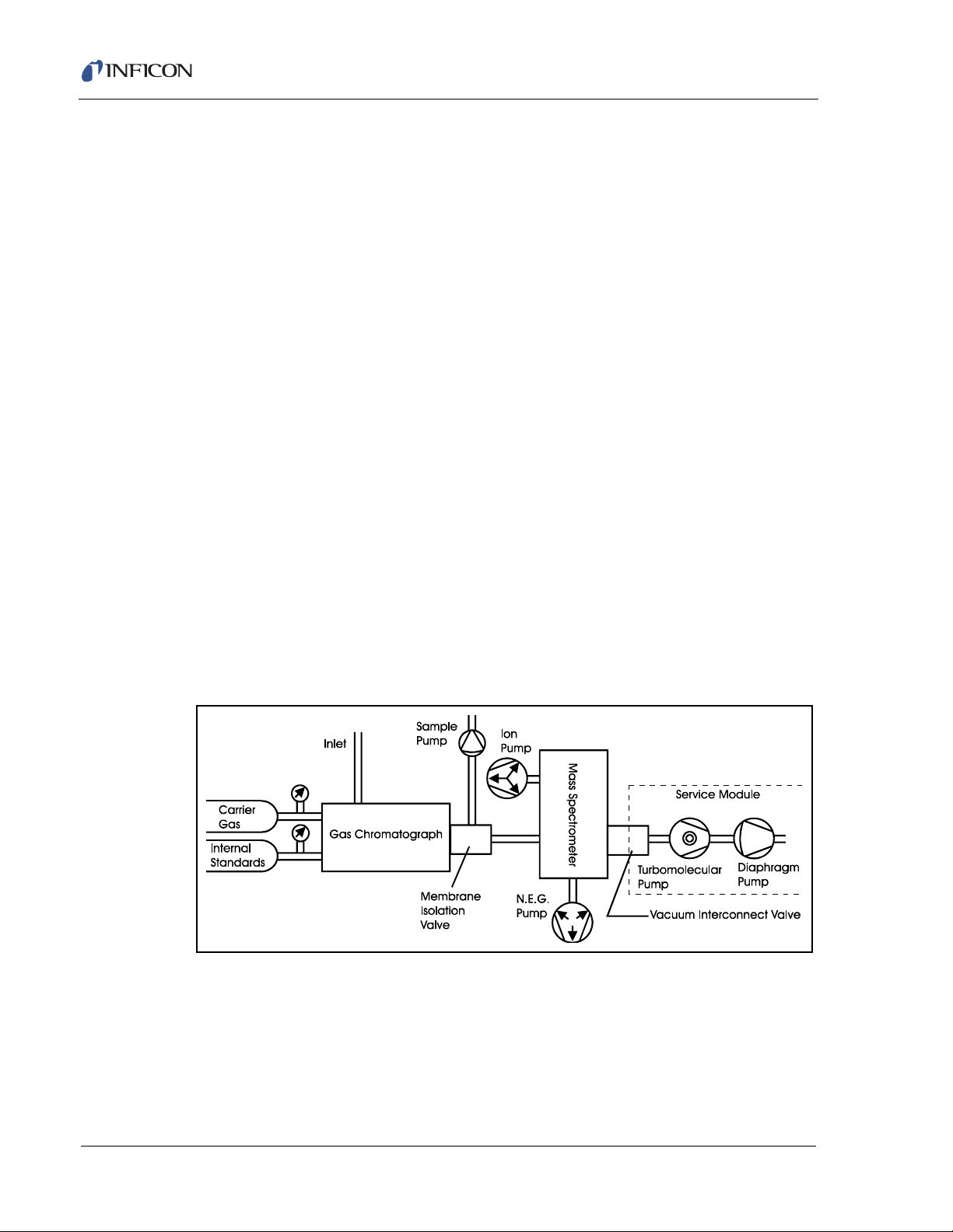
1.4 Theory of Operation
The HAPSITE combines two analytical techniques, Gas Chromatography and
Mass Spectrometry, to separate, identify, and measure the organic components in
a gas phase sample. Using a flow of inert Nitrogen Carrier Gas, the Gas
Chromatograph (GC) performs a time separation (Retention Time) of the sample
compounds. The separation order is primarily based on increasing compound
boiling point. The Mass Spectrometer (MS) detects and identifies the eluting
compounds by breaking the molecules apart and detecting the fragments. The
resulting mass spectrum is compared to a library of mass spectra to identify the
compound.
HAPSITE Smart Plus Operating Manual
(This depends on the details of the
method being used.)
The Gas Chromatography technique cannot always separate compound mixtures
into individually eluting compounds. Some of the eluting responses or peaks may
contain two, three, or more compounds which have taken the same time to
progress (elute) through the Gas Chromatograph. GC identification of compounds
is limited to matching the retention time of the unknown compound to that of a
known standard. See section 1.6.1, Gas Chromatograph, on page 1-5 for more
information on how the GC works. In order to further identify and measure the
individual components of such mixtures, the gas stream is directed into the Mass
Spectrometer.
IPN 074-472-P1C
In the Mass Spectrometer, the gas stream of eluting compounds is bombarded with
electrons. The electrons fracture the molecules into a characteristic combination of
smaller molecules or mass fragments. The Mass Spectrometer (MS) measures
and plots the response of these mass fragments to display a mass spectrum. See
section 1.6.2, Mass Spectrometer, on page 1-7 for more information on how the
MS works.
The introduction of a mixture of many compounds directly to the MS would produce
a very complex and uncharacteristic mass spectrum. However, because the GC
has largely separated the gases, the MS can usually differentiate between the few
co-eluting compounds. This differentiation provides very precise identification and
measurement of the quantity of each compound. Qualitative identification can be
made by comparing the unknown compound spectrum to the NIST mass spectral
1 - 3
Page 32
HAPSITE Smart Plus Operating Manual
library (included with the Plus IQ software). See section 9.8, NIST Library
Searches, on page 9-24 for more information. Quantitative identifications can be
made by analyzing standards of known concentration and creating a target
compound library of concentration response curves. See Chapter 12, Target
Compound Methods for more information.
In summary, the GC first separates the gaseous compounds by time. Then the MS
identifies and measures the gases contained in each of the time-separated peaks.
This enables the GC/MS system to report the specific identity and concentration of
each of the compounds present in the initial pulse of gas analyzed.
1.5 Instrument Overview
The HAPSITE system is comprised of two modules:
the HAPSITE, also known as the Analytical Module, and
the Service Module.
The HAPSITE is comprised of many systems and subsystems. Figure 1-1 shows
a diagram of the major subsystems. These subsystems include the several pumps
used to provide flow and vacuum.
The Service Module components are identified in Figure 1-1, everything else is
housed in the HAPSITE. The Service Module and the HAPSITE module contain a
Vacuum Interconnect Valve and electrical connectors through which their vacuum
systems join. The modules communicate when the two modules are coupled
together.
Figure 1-1 Major HAPSITE Subsystems
IPN 074-472-P1C
1 - 4
Page 33

1.6 Description Of Subsystems
The HAPSITE is comprised of the following subsystems:
Gas Chromatograph
Mass Spectrometer
Vacuum System
Electronic Systems
Software Systems
1.6.1 Gas Chromatograph
The HAPSITE’s GC system utilizes Nitrogen as the Carrier Gas to transport
analytes through a column, a narrow-bore fused silica tube 30 meters in length,
and then on to the detector. The Nitrogen is referred to as the mobile phase.
The inside of the column is coated with a thin layer of a material known as the
stationary phase. The stationary phase is a chemical which can selectively attract
components in a sample mixture. The mixture of sample compounds in the mobile
phase interact with the chemicals of the stationary phase. The chemicals which
have the fastest interactions will elute (exit) off the column first. The HAPSITE also
utilizes a temperature programmable GC. The oven is programmed to increase the
temperature gradually (called ramping) to improve compound separation while
decreasing analysis time. As the temperature increases, the compounds with the
lowest boiling points will elute first with the standard non-polar phase coated
column installed. More selective columns may be ordered for specific applications.
HAPSITE Smart Plus Operating Manual
The time taken by an individual compound to travel from injection into the system
until the compound elutes from the column is referred to as the Retention Time
(RT). If the GC conditions remain constant, the same compound will elute from the
column at nearly the same retention time for each injection.
An important part of the operation of the HAPSITE is the use of Internal Standards.
IPN 074-472-P1C
They verify the performance of the Gas Chromatograph, as well as, the tuning and
sensitivity of the mass spectrometer. The Internal Standards are two volatile
organic gases at low concentrations which are added to the sample inlet flow. The
Internal Standards’ Retention Times and responses are used as references for
instrument performance.
Figure 1-2 is a graph of eluting organic gases from the Gas Chromatograph that is
plotted as a function of time from the injection of a pulse of mixed compounds. The
graph demonstrates the separation of the various compounds from each other by
the action of the Gas Chromatograph, as described above. This plot is called a
Total Ion Chromatogram (TIC).
1 - 5
Page 34
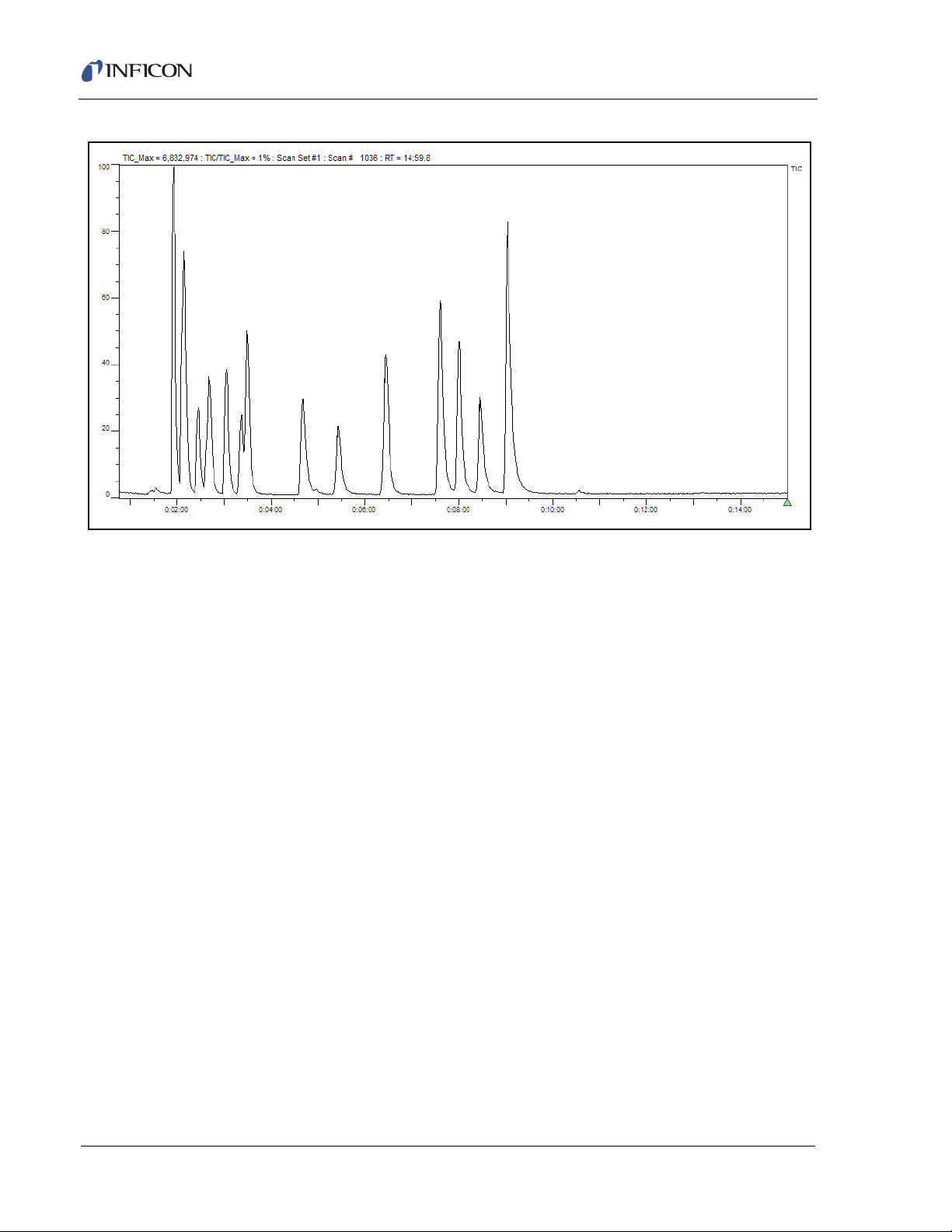
HAPSITE Smart Plus Operating Manual
Figure 1-2 Total Ion Chromatogram
The performance of the column is affected by temperature, therefore, the column
is housed in a temperature controlled oven.
The gas chromatograph performs many operational functions, including injecting
the sample, analyzing the sample, flushing the system, and tuning the system.
GC/MS measurement begins with the Sample Pump drawing the gas to be
analyzed into the Sample Loop. It then uses the pressure of the Carrier Gas to flush
the sample from the Sample Loop on to the pre-column and the analytical column.
This step is termed injection.
When the analytes have passed through the pre-column, the Carrier Gas is
directed to the junction of the two columns where the Carrier Gas continues to
transport the analytes through the analytical column while back-flushing the
pre-column to prepare the pre-column for the next analysis sequence. This
back-flush continues throughout the next filling of the Sample Loop.
1.6.1.1 Membrane Isolation Valve
Gas exiting the analytical column crosses the face of a membrane mounted in the
membrane isolation valve. This membrane has the special characteristic of
transmitting the flow of organic compounds to the Mass Spectrometer, while
effectively blocking the flow of inorganic gases (such as the Nitrogen Carrier Gas).
When the membrane isolation valve is opened, the appropriate gases are
permitted to enter the Mass Spectrometer for analysis while the Mass
Spectrometer remains under vacuum. The membrane’s performance is affected by
temperature fluctuations and requires housing in a temperature-controlled zone.
IPN 074-472-P1C
1 - 6
Page 35
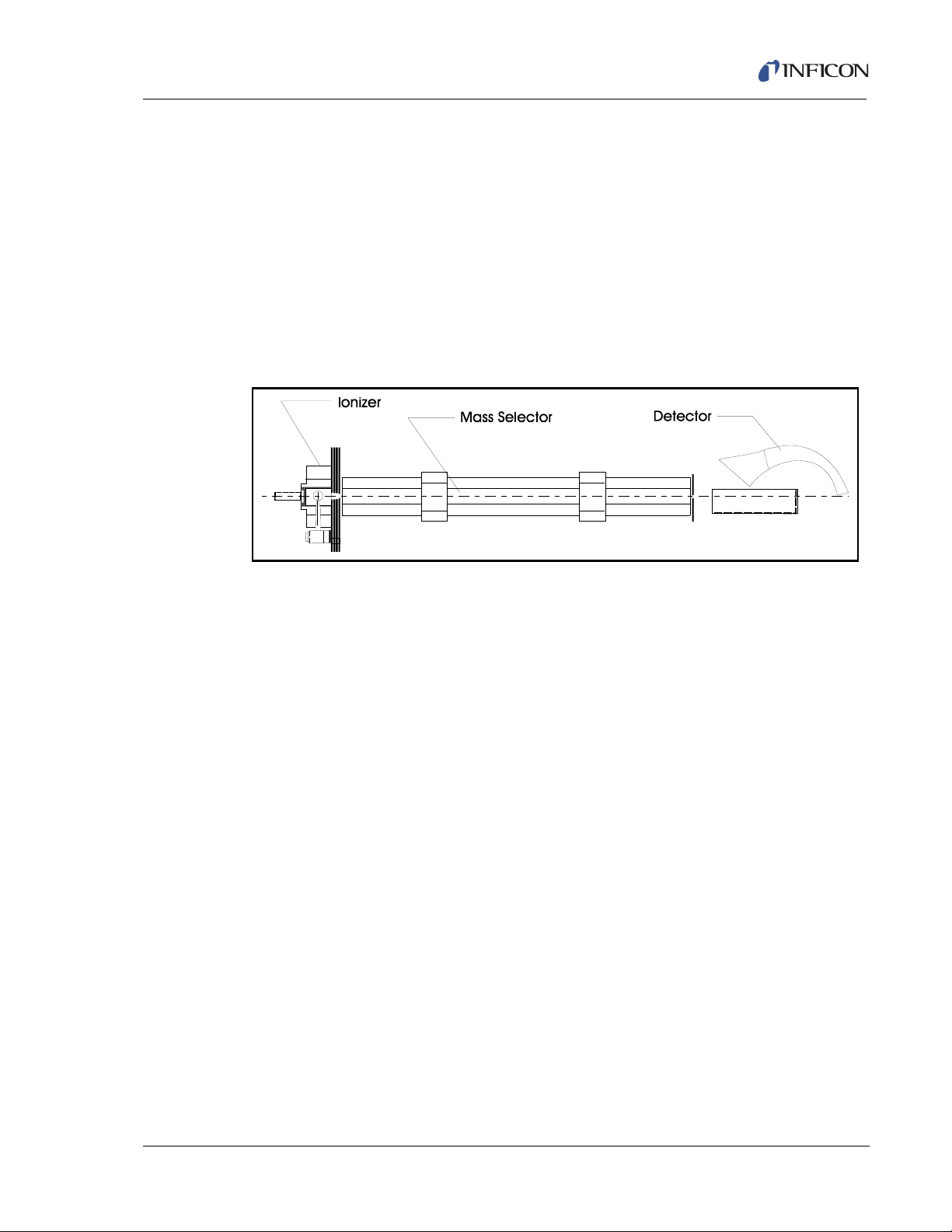
In the Survey mode of operation, in which air samples are passed directly to the
mass spectrometer, the sample pump draws the air sample directly across the
membrane with the isolation valve in the open position.
1.6.2 Mass Spectrometer
The Mass Spectrometer is comprised of three basic physical systems: the Ionizer,
the Mass Selector, and the Ion Detector. These are mounted together in a vacuum
manifold which also includes an inlet, two vacuum pumps, and a portion of the
Vacuum Interconnect Valve, as shown in Figure 1-1 on page 1-4. Figure 1-3 is a
representation of the three sub-systems of the mass spectrometer.
Figure 1-3 Three Subsystems of the Mass Spectrometer
HAPSITE Smart Plus Operating Manual
The inlet flow from the membrane isolation valve is brought directly to the Ionizer.
Within the ionizer, the component introduced from the inlet flow is subjected to a
bombardment of electrons which are boiled off the hot filament. Collisions with the
energetic electrons remove one electron from some of the gas molecules, leaving
them with a net positive charge. This process is termed ionization. Other gas
molecules are fractured into smaller molecules, some of which are also ionized.
The remaining stream of gas continues out the far side of the ion volume and is
pumped away by the vacuum pump system.
The ionized molecules, or ions, are driven from the ionizer toward the mass
selector by the different voltages on the ion volume and the focusing plates. As the
ions move through the holes in these plates, the ions are formed into a nearly
IPN 074-472-P1C
parallel beam of mixed ions of nearly the same energy.
The Mass Selector (or mass filter) is a quadrupole analyzer. The quadrupole
analyzer is comprised of four parallel rods, mounted with precise alignment and
spacing. Opposite rods are electrically connected together. The two pairs of rods
are connected to a radio frequency (RF) voltage 180
o
out of phase with each other.
In addition, the two pairs of rods have a direct current (DC) voltage applied to them;
positive on one pair, negative on the other.
The Ion Beam is directed down the center of the array of rods. At any specific
combination of RF and DC fields, some ions are light enough to oscillate
harmonically with the RF field. This oscillation causes them to pick up energy and
increase speed until the ions impact one of the rods and are neutralized. The DC
field acts upon the heavier ions resulting in their movement from the center towards
1 - 7
Page 36

HAPSITE Smart Plus Operating Manual
the rods. Once on the rod, the heavier ion is neutralized. At a specific combination
of RF and DC fields, ions of a specific mass will be able to transit the rod structure
and emerge at the exit end to be detected.
When the ions emerge from the Mass Selector, the ions are directed to the
detector. The active element of the detector is an Electron Multiplier. The Electron
Multiplier responds to the arrival of each individual ion with a cascade of electrons,
each of which generates more electrons. The result is a small burst of electrical
current in response to each ion emerging from the mass selector. The signal from
the electron multiplier is connected to the electronic amplifier and data-handling
system outside the vacuum.
In order to determine the constituents of the gas mixture, the ratio of RF to DC field
strengths is varied (swept) to permit progressively heavier ions to transit the mass
selector. The sweep, or scan, over the full range of masses (from 1 to 300 AMU)
only takes about 100 milliseconds; the sweep is usually repeated many times to
statistically improve the quality of the data. This produces the mass spectrum, a
plot of the partial pressure (or population or intensity or amplitude) of each mass.
The mass spectrum is compared with a library of mass spectra characteristic of
many individual compounds, and the HAPSITE reports the compounds which
match the observed spectrum.
Alternatively, the Mass Spectrometer can remain tuned to a specific mass or set of
masses. The instrument measures the partial pressure of only those masses as a
function of time. Operation in this mode, termed selected ion monitoring (SIM),
permits very sensitive measurement of the presence of one or a few compounds
which have already been identified.
1.6.3 Vacuum System
The Mass Spectrometer is operated in a vacuum for several reasons.
The ions must travel nearly a foot from the ionizer through the quadrupole to
the Electron Multiplier without colliding with another molecule. (A collision
would modify their trajectory, and possibly their charge.)
The gas to be analyzed must be free from interference from other unknown
gases.
The hot filament which generates the electrons would be destroyed if operated
at atmospheric pressure in the presence of oxygen.
The vacuum is initially provided by the Turbo-Molecular and Diaphragm Pumps in
the Service Module. When a good vacuum level is achieved and the pumps in the
HAPSITE are turned on, the Vacuum Interconnect Valve is closed. At this point, the
Service Module can be disconnected. The Service Module is not needed again
until the NEG Pump in the HAPSITE must be changed.
IPN 074-472-P1C
1 - 8
Page 37

HAPSITE Smart Plus Operating Manual
The two vacuum pumps of the HAPSITE continue to provide the pumping
necessary for operation. These two pumps are the non-evaporate getter (NEG)
Pump and the smaller Sputter-ion Pump. The NEG Pump incorporates a special
zirconium alloy, arranged in sintered disks, which when heated adsorb gas
molecules very aggressively.
Over time, the sintered disks gradually become fully saturated with gas molecules
and the pumping speed drops. The instrument detects the resultant rise in
operating pressure (loss of vacuum) and the software signals that the pump must
be replaced.
The NEG Pump is very effective in removing the active gases, but the NEG Pump
does not remove noble gases. The sputter-ion pump is provided to remove argon,
neon, helium, krypton, and xenon which would otherwise accumulate in the mass
spectrometer. The accumulation would raise the mass spectrometer pressure and
interfere with operation.
The Turbo Molecular Pump in the Service Module is actually a compound pump,
incorporating turbo molecular stages for high pumping speeds at low pressure, and
molecular drag stages to provide good compression of the gas at higher pressures.
Even with the drag stages, this pump is unable to compress the gas enough to
exhaust the gas into atmospheric pressure. An additional Diaphragm Roughing
Pump is provided.
The Diaphragm Pump consists of four stages, in series. The Diaphragm Pump
draws the gas from the exhaust of the compound pump and compresses the
exhaust gas sufficiently to discharge the exhaust into the atmosphere.
1.6.4 Electronic Systems
The electronic systems in the HAPSITE are considered in four groups:
Mass Spectrometer Control
Gas Chromatograph Control
IPN 074-472-P1C
1.6.4.1 Mass Spectrometer Control
Main Processor
Interfaces
The Mass Spectrometer control electronics include the programmable DC and RF
power supplies for the Mass Selector, the DC power supplies for the filament, the
Electron Multiplier, the Sputter-ion Pump, and the A/D converter for the signal from
the Electron Multiplier.
1 - 9
Page 38

HAPSITE Smart Plus Operating Manual
1.6.4.2 Gas Chromatograph Control
The Gas Chromatograph control circuitry includes the power supplies for the
solenoid valves, the ovens and the heated inlet line. It also contains the control
logic for all the valves and heaters of the GC system.
1.6.4.3 Main Processor
The main processor is supported by solid state memory and is located in the central
electronics assembly. The main processor accepts data from many points within
the system. It controls all the other electronic sub-assemblies, both in routine
operation and in managing the data-taking methods.
1.6.4.4 Interfaces
There are several input/output devices within the HAPSITE. These include the front
panel touchscreen, keypad and display, the USB drive, the crossover cable
connection, the wireless connection, the hand control unit, the power and logic
connections to the Service Module, Headspace Sampling System, SituProbe and
the pins which read the details of the gas mixture from the gas canisters.
1.6.5 Software Systems
The HAPSITE operates with two separate software systems. The instrument itself
incorporates control and analysis software. This control software accepts inputs
from the touchscreen, keypad, and other interfaces, and commands the operation
and sequencing of all the systems and subsystems. The analysis software
analyzes the data from the mass spectrometer, accesses the libraries as required,
and displays the results of the analyses on the front panel. The control software
allows a method to be started with minor modifications from the front panel. Design
or substantive modifications of the method require the use of the HAPSITE
Application software on an external PC.
The HAPSITE Application software, Plus IQ, is a Windows® XP and Windows®
2000 based system for use in the accessory Laptop. The Plus IQ software is used
to design and modify the methods under which the HAPSITE can operate, view the
data, analyze the results, and generate and print reports. The Laptop is linked to
the HAPSITE by a crossover cable or wireless connection, which permits
uploading of data from the HAPSITE and downloading new or modified methods to
the HAPSITE.
IPN 074-472-P1C
1 - 10
Page 39

2.1 Ship Kit Packing Lists
. 036-0015 . . . . .Shoulder Strap
. 074-290 . . . . . .Instruction Sheet
(Shoulder Strap)
. 059-0329 . . . . .Quick Disconnect Stem
. 070-0972 . . . . .Plunger Contact (Bag of 4)
. 074-490-P1. . . .Quick Start Guide
. 074-5010-G1. . .Manual CD
. 074-5012-G1. . . Basic Front Panel Operation Training CD
. 600-1319-P2. . .Ethernet Cable
. 930-021-G1. . . .Gasket Kit
. 930-022-G1. . . .Tool Kit
. 930-249-G2. . . .Concentrator Cover
. 930-251-G1. . . .Concentrator Tube (Tenax®-TA)
. 930-716-G1. . . .Concentrator Tube
(Tri-Bed)
. 930-0221-G1. . .Concentrator Nut and Ferrule
. 930-0231-G1. . .Probe Nut and Ferrule
. 930-2020-G1. . .Cap Kit
. 930-4652-P1. . .Permanent Marker
. 930-612-P1. . . .USB Flash Drive
Special Cords for International Ship Kits
Extra Cords for SM and Battery Charger (Qty. 2)
Ship Kit . . . . . . .Location . . Cord
. 930-850-G9. . . .USA . . . . . N/A
. 930-850-G12. . .Australia . . 068-0393
Box 1 Contents
2.2 930-850-G9, G12 Ship Kit Contents
HAPSITE Smart Plus Operating Manual
Chapter 2
HAPSITE Components and Assemblies
The following items are provided in a typical HAPSITE Smart Plus 930-850-G9,
G12 Ship Kit.
Figure 2-1 930-850-G9, G12 Ship Kit Contents Box 1 Contents
IPN 074-472-P1C
2 - 1
Page 40
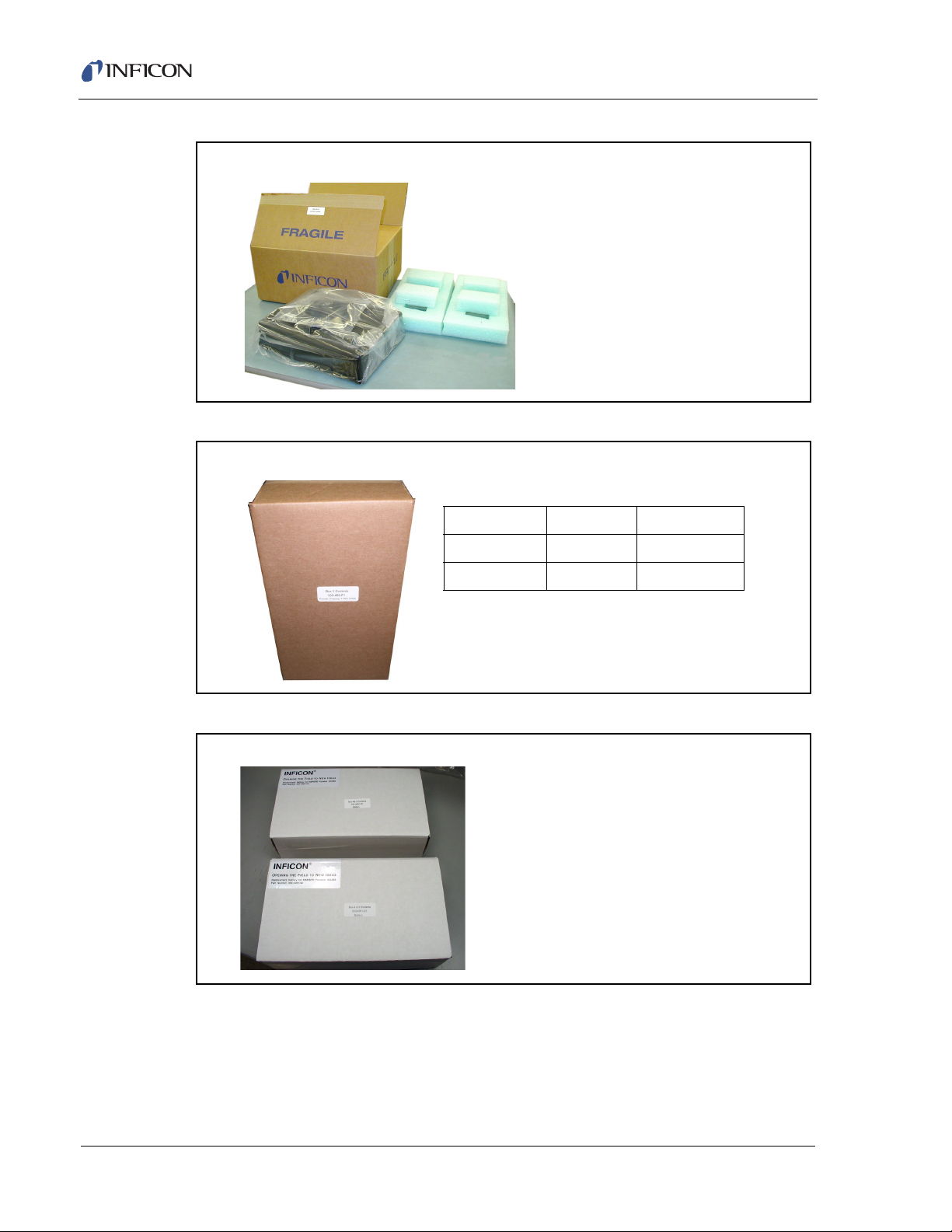
HAPSITE Smart Plus Operating Manual
Box 2 Contents
. . . . 930-470-G1 Battery Charger
. . . . 24 V Power Supply (see table)
Power Supply Ship Kit Usage
930-469-P1 930-850-G9 110 V USA
930-469-G3 930-850-G12 230 V UK
Box 3 Contents
. . . . . In two separate boxes,
Battery Pack NiMH (930-4061-G1)
Box 4 and 5 Contents
Figure 2-2 930-850-G9, G12 Ship Kit Box 2 Contents
Figure 2-3 930-850-G9, G12 Ship Kit Box 3 Contents
Figure 2-4 930-850-G9, G12 Ship Kit Box 4 and 5 Contents
2 - 2
IPN 074-472-P1C
Page 41

HAPSITE Smart Plus Operating Manual
. . 036-0015 . . . . . Shoulder Strap
. . 074-290 . . . . . . Instruction Sheet
(Shoulder Strap)
. . 059-0329 . . . . . Quick Disconnect Stem
. . 070-0972 . . . . . Plunger Contact (Bag of 4)
. . 074-490-P1 . . . Quick Use Guide
. . 074-5010-G1 . . Manual CD
. . 600-1319-P2 . . Ethernet Cable
. . 930-021-G1 . . . Gasket Kit
. . 930-022-G1 . . . Tool Kit
. . 930-249-G2 . . . Concentrator Cover
. . 930-251-G1 . . . Concentrator Tube (Tenax®-TA)
. . 930-716-G1 . . . Concentrator Tube
(Tri-Bed)
. . 930-0221-G1 . . Concentrator Nut and Ferrule
. . 930-0231-G1 . . Probe Nut and Ferrule
. . 930-2020-G1 . . Cap Kit
. . 930-4652-P1 . . Permanent Marker
. . 930-612-P1 . . . USB Flash Drive
Special Cords for International Ship Kits
Extra Cords for SM and Battery Charger (Qty. 2)
Ship Kit . . . . . . Location. . . Cord
. . 930-850-G10 . . Europe. . . . 068-0151
. . 930-850-G11 . . UK . . . . . . . 068-0388
Box 1 Contents
2.3 930-850-G10, G11 Ship Kit Contents
The following items are provided in a typical HAPSITE Smart Plus 930-850-G10,
G11 Ship Kit. See Figure 2-1.
Figure 2-5 930-850-G10, G11 Ship Kit Box 1 Contents
IPN 074-472-P1C
2 - 3
Page 42

HAPSITE Smart Plus Operating Manual
Box 2 Contents
. . . . 930-470-G1 Battery Charger
. . . . 24 V Power Supply (see table)
Power Supply Ship Kit Usage
930-469-P2 930-850-G10 230 V European
930-469-G3 930-850-G11 230 V UK
Box 3 Contents
. . . . . In two separate boxes,
Battery Pack NiMH (930-4061-G1)
Box 4 and 5 Contents
Figure 2-6 930-850-G10, G11 Ship Kit Box 2 Contents
Figure 2-7 930-850-G10, G11 Ship Kit Box 3 Contents
Figure 2-8 930-850-G10, G11 Ship Kit Box 4 and 5 Contents
2 - 4
IPN 074-472-P1C
Page 43

2.3.1 Ship Kits Box 3 and 4
CAUTION
AC to DC Power Converter Batteries
Figure 2-9 USA 24V Power Supply (AC To DC Power Converter) - Box 3
and Battery (2 Shipped) - Boxes 4 and 5
In addition, a Laptop computer and accessories are shipped. The ship kits vary
depending on the type of Laptop ordered. The Laptop kits will include the Plus IQ
Software CD and NIST Library Install CD.
HAPSITE Smart Plus Operating Manual
2.4 Basic Assembly
The HAPSITE should be operated a minimum of every 3
weeks. Recommended storage is in Extended Standby.
Figure 2-10 HAPSITE Parts for Basic Assembly
IPN 074-472-P1C
The basic assembly of the HAPSITE can be accomplished in six easy steps.
2 - 5
Page 44

HAPSITE Smart Plus Operating Manual
2.4.1 Attaching the Probe
To attach the Probe line, plug the LEMO® connector into the port on the top of the
HAPSITE as illustrated in Figure 2-11.
Figure 2-11 Attaching the LEMO Connector on the Probe Line to the HAPSITE
HINT: Save all of the caps to cover ports in the event the instrument needs to be
decontaminated. Spare caps are provided in the Ship Kit. See Figure 2-12.
Figure 2-12 Spare Cap Kit
IPN 074-472-P1C
2 - 6
Page 45

2.4.2 Remove Exhaust (Vent) Cap
CAUTION
WARNING
The red exhaust (vent) cap is located on the right side of the HAPSITE near the
back. This exhaust (vent) cap must be removed
properly. The HAPSITE is shipped with the cap removed. See Figure 2-13.
Figure 2-13 Exhaust Cap Removed
HAPSITE Smart Plus Operating Manual
for the HAPSITE to function
The exhaust cap must be removed for proper HAPSITE
operation.
Samples will vent to breathing area through the exhaust.
To avoid inhalation, attach tubing and vent to a hood or
attach an activated charcoal filter if sample is hazardous.
IPN 074-472-P1C
2 - 7
Page 46

HAPSITE Smart Plus Operating Manual
CAUTION
Press
Lever
2.4.3 Installing the Gas Canisters
Only open the front panel in a dry, uncontaminated area.
The gas canisters must be installed inside the front panel. Open the panel by
placing thumbs on the top of panel and pulling down. This technique avoids
damaging the sealing gasket with fingernails.
The purple banded Nitrogen (also known as Carrier Gas) canister must be inserted
into the top round opening of the HAPSITE. The yellow banded Internal Standard
canister must be inserted into the bottom round opening.
To insert the canisters, place them into the opening with the top facing into the
HAPSITE. Depress the "PUSH" lever while inserting. The canister will slide further
into the HAPSITE. Release the "PUSH" lever and remove hands from canister.
Gently pull on the cans to ensure the cans are locked into place. See Figure 2-14.
Figure 2-14 Canister Placement
Figure 2-15 Installing A Gas Canister
NOTE: The position of the gas canisters should not be interchanged. To prevent
improper placement, the Internal Standard canister has a Teflon® ring that
surrounds the inner stem on the top of the can. Do not force the canisters
into the wrong location as this would result in contamination of the
HAPSITE.
IPN 074-472-P1C
2 - 8
Page 47

HAPSITE Smart Plus Operating Manual
WARNING
CAUTION
Carrier Gas
Canister
Internal
Standard
Canister
Press
Lever
2.4.3.1 How to Change or Remove a Gas Canister
Push the lever located on the right of the canister. The canister will release. (A
slight twist of the canister may be required.) Remove the canister. Refer to Figure
2-16 on page 2-9.
NOTE: The Nitrogen canister will need to be replaced after roughly 8 hours of use.
The Internal Standard canister will need to be replaced after 3 to 4 days of
continuous use. These numbers are guidelines and will vary.
Do not refill the canisters. Bodily injury may result.
Canisters are designed to be disposable and may fail if
filling is attempted.
Closing the front panel when the canisters are not
properly installed may damage the HAPSITE and/or
canisters.
IPN 074-472-P1C
Figure 2-16 Canister Removal
2 - 9
Page 48

HAPSITE Smart Plus Operating Manual
Battery
2.4.4 Install Battery
Insert the battery by sliding it into the rectangular opening to the left of the gas
canisters. Push firmly and listen for the battery to click into place. Once the battery
is installed, gently pull on the battery to make sure the battery is locked into place.
See Figure 2-17.
Figure 2-17 Battery Insertion
2.4.5 Connect the AC To DC Power Converter Power Supply
The AC to DC power converter plugs into the four prong plug on the left side of the
HAPSITE (when facing the front of the HAPSITE). A red dot on the connector
aligns with the corresponding red line on the receptor of the HAPSITE (if the red
dot is not visible on the HAPSITE, the red dot on the power supply should be facing
forward.) Plug the AC to DC power converter into an outlet. See Figure 2-18.
Figure 2-18 The AC To DC Power Converter Power Supply
2.4.6 Connect Laptop (if desired)
The HAPSITE Plus has two possible configurations for connecting to a Laptop
computer. The standard connection is via a crossover cable. All instruments
manufactured after December 2006 will have a wireless communication
connection option. Older instruments may also have the wireless option if a
wireless upgrade was installed.
IPN 074-472-P1C
2 - 10
Page 49
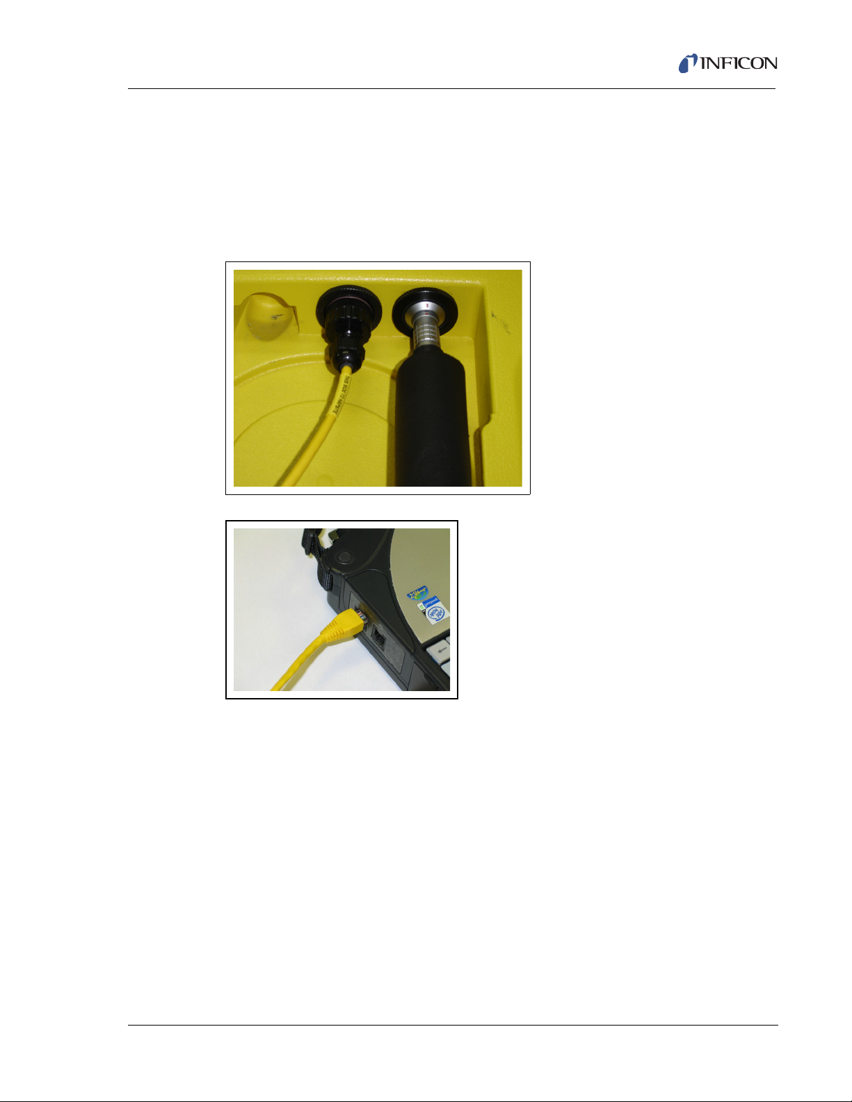
HAPSITE Smart Plus Operating Manual
2.4.6.1 Connect Laptop with Yellow Crossover Cable
Unscrew the cap on the port next to the probe connection. Plug in the yellow
crossover cable into this port. The opposite end plugs into the COM1 port on the
Laptop computer. Once connected, the crossover cable provides the
communication connection between the HAPSITE and Laptop computer. See
Figure 2-19 and Figure 2-20.
Figure 2-19 Crossover Connection to HAPSITE
Figure 2-20 Crossover Connection to Laptop
2.4.6.2 Connect Laptop with Wireless Connection
IPN 074-472-P1C
See Chapter 4, Wireless and Touch Screen Options for information on enabling the
wireless connection.
2 - 11
Page 50

HAPSITE Smart Plus Operating Manual
2.5 Helpful Guidelines
A set of helpful guidelines to keep the HAPSITE safe and operational.
DON’T…
Ship with a battery installed.
Start up on battery power, if possible.
Draw liquid into the instrument.
Go into a potentially explosive
environment without safety checks
(the HAPSITE is not intrinsically safe).
Pressure wash the HAPSITE or
immerse in water.
Linearize DACS without the help of an
INFICON representative.
Sample strong acids (below pH 2) or
strong bases (above pH 11).
Use force when assembling any
HAPSITE system components.
Modify default methods without
changing their name.
Sample for Sulfur Mustard (HD) with
the VX conversion tube installed.
Abort an Analyze (GC/MS) method
during a sample run.
Over-tighten concentrator tube nuts.
Block the exhaust vent on the
HAPSITE.
Use the NEG Pump and Service
Module pumps together.
Use expired Internal Standard gas.
Use a LAN or Ethernet cable between
Laptop and HAPSITE.
DO…
Leave a battery installed when
operating even when AC is connected.
Run a background blank once per
week or more.
Use Extended Standby instead of
Shutdown whenever possible.
Place appropriate caps over openings
before decontaminating.
Use 5% or 10% bleach solution or
soap-and-water to decontaminate
according to local SOP.
Only use thumbs to open the front
panel.
Attempt to reboot as a first step to
correct operational discrepancies.
Screen potentially high concentration
sample with Survey method to reduce
the risk of saturation.
Use the VX conversion tube for
identification (and quantification) of VX
and R-33.
Use crossover cable between Laptop
and HAPSITE.
Take a training course or refresher
training.
Contact INFICON at
HAPSITE.Support@INFICON.com,
800.223.0633 for help.
IPN 074-472-P1C
2 - 12
Attach a bag sample without first
checking the ferrules in the probe nut
.
Page 51

2.6 HAPSITE Configurations
There are 6 basic configurations for the HAPSITE. The first three can either be in
portable mode or connected to AC power. Each configuration can be run with or
without the Laptop computer connected.
Configuration 1 - HAPSITE with Probe and Sample Loop or Concentrator
Configuration 2 - HAPSITE with Headspace Sampling System and Sample Loop
or Concentrator
Configuration 3 - HAPSITE with SituProbe and Sample Loop or Concentrator
Configuration 4 - HAPSITE mounted on Service Module with Probe and Sample
Loop or Concentrator
Configuration 5 - HAPSITE mounted on Service Module with Headspace
Sampling System and Sample Loop or Concentrator
Configuration 6 - HAPSITE mounted on Service Module with SituProbe and
Sample Loop or Concentrator
HAPSITE Smart Plus Operating Manual
2.7 Headspace Sampling System
The Headspace Sampling System is an accessory used to test water and solid
samples. Samples are heated to release any VOC’s into the sample vial
headspace. The needle, which is inserted into the vial, samples the headspace.
The sample is then transferred into the HAPSITE via the transfer line.
For additional information on the Headspace Sampling System see Chapter 13,
Headspace Sampling System.
2.7.1 Headspace Sampling System - Components Received
Headspace Sampling System (HSS) — The main module includes the following:
Headspace sampling needle assembly
IPN 074-472-P1C
Heater block with four sample wells
Compartment for loading an INFICON Nitrogen Carrier Gas canister
Compartment for loading an INFICON rechargeable battery, INFICON part
number 930-4061-G1
Swagelok® connection for use with an external supply of pressurized Nitrogen
Power supply connection
Transfer Line connection
2 - 13
Page 52

HAPSITE Smart Plus Operating Manual
Transfer Line (INFICON part number 931-401-P2) — A directional heated line
which connects the HSS to the HAPSITE. The line transfers the sample from the
HSS to HAPSITE and provides communication between the two instruments. Each
end is labeled to ensure proper orientation.
Transfer Line Insulation (INFICON part number 931-405-P1) — This foam sleeve
is used as insulation for the Transfer Line. The insulation extends battery life by
reducing the energy required to heat the line. Once heated, it helps to maintain the
temperature.
Replacement Needle Kit (INFICON part number 931-402-P1)— A new needle
assembly for when the original needle is worn, plugged, or broken.
HSS Carrying Shoulder Strap (INFICON part number 036-015)— A strap which
connects to the mounts on the sides of the HSS. It facilitates carrying the
instrument between the office and the field.
Y-Cable (INFICON part number 600-1131-P30)— A power cable to split the power
from the AC to DC power converter to both the HAPSITE and the HSS or
SituProbe.
2 - 14
IPN 074-472-P1C
Page 53
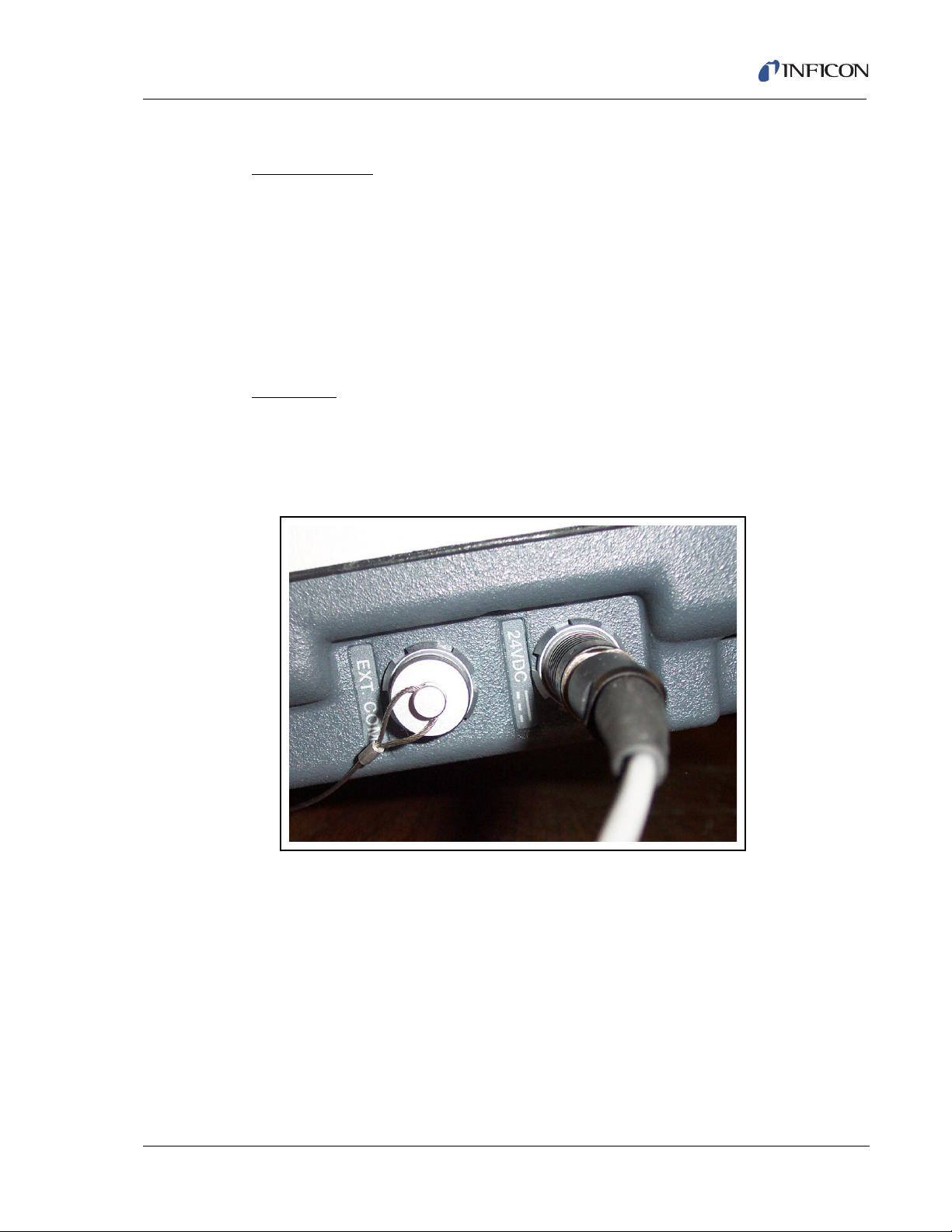
HAPSITE Smart Plus Operating Manual
2.7.2 Installing the Headspace Sampling System
Required Parts
The following items are needed to install the HSS:
Headspace instrument
Y-cable power splitter
Transfer line
Carrier Gas
Charged Battery
Procedure
1 Install a fully charged battery into the HAPSITE.
2 Unplug the AC to DC power converter power supply from the HAPSITE. See
Figure 2-21.
Figure 2-21 Power Supply to HAPSITE from AC To DC Power Converter
IPN 074-472-P1C
3 Connect the single end of the Y-cable (see Figure 2-22) to the power supply
connector removed in step 2.
4 Plug one end of the Y-cable into the HAPSITE 24 V(dc) connector.
5 Plug the other end of the Y-cable into the back of the HSS. See Figure 2-22.
2 - 15
Page 54
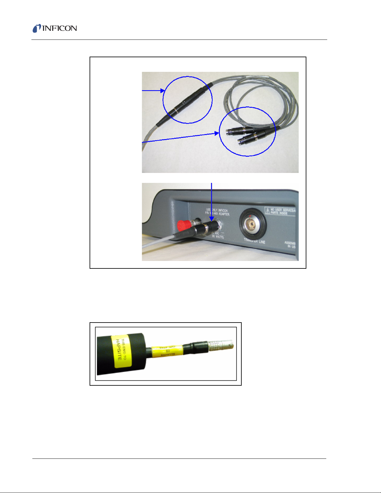
HAPSITE Smart Plus Operating Manual
Y-C onne ctor
and
24 V(dc) Supply
Cable
Plug into
HAPSITE
and
HSS
HSS Connection
Figure 2-22 Power Supply Y-cable and Back of HSS
6 Properly align the labels on the foam insulation and Transfer Line. The end of
the insulation labeled in yellow THIS END TO HAPSITE should coincide with
the end of the Transfer Line labeled in yellow THIS END TO HAPSITE. See
Figure 2-23.
Figure 2-23 HAPSITE End of Transfer Line
IPN 074-472-P1C
2 - 16
Page 55
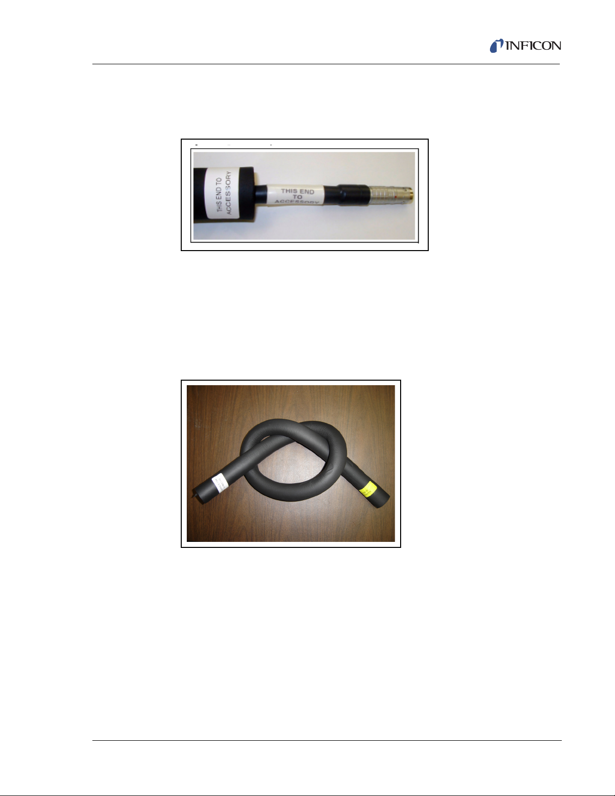
HAPSITE Smart Plus Operating Manual
7 The white label THIS END TO ACCESSORY on the insulation should coincide
with the white label THIS END TO ACCESSORY on the Transfer Line. See
Figure 2-24. When alignment is correct, slide the insulation into place.
Figure 2-24 Accessory End of the Transfer Line
8 Install the Transfer Line between the HAPSITE and Headspace Sampling
System. First, disconnect the Probe from the HAPSITE. Install the LEMO
connector, which is labeled, THIS END TO HAPSITE, in the HAPSITE
connector. The opposite end labeled, THIS END TO ACCESSORY, will
connect to the rear of the Headspace Sampling System. See Figure 2-26. Make
sure the red dots on the Transfer Line connectors align with the marks on the
HAPSITE and Headspace Sampling System connectors.
Figure 2-25 Attaching the Transfer Line to the HAPSITE
IPN 074-472-P1C
2 - 17
Page 56
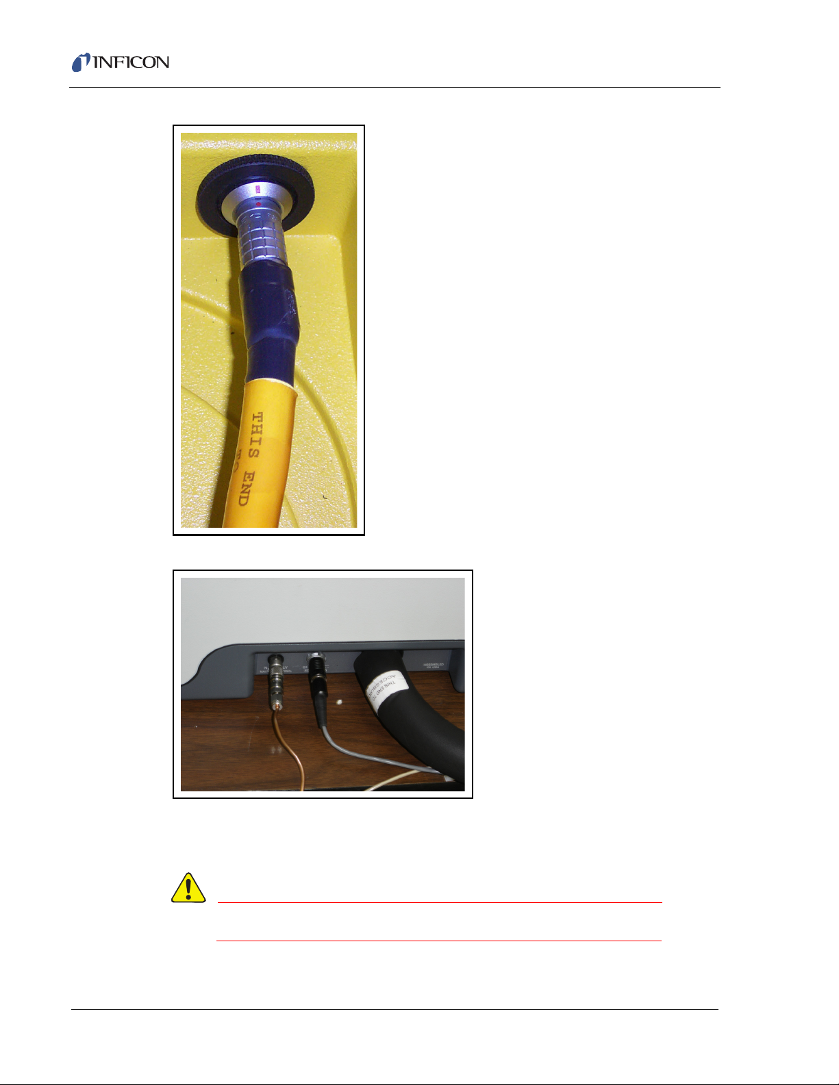
HAPSITE Smart Plus Operating Manual
WARNING
Figure 2-26 This End to HAPSITE
Figure 2-27 This End to Headspace
9 Connect a pressurized Nitrogen cylinder or install a Nitrogen can into the
Headspace instrument.
Nitrogen canisters and cylinders are under pressure.
IPN 074-472-P1C
2 - 18
Page 57
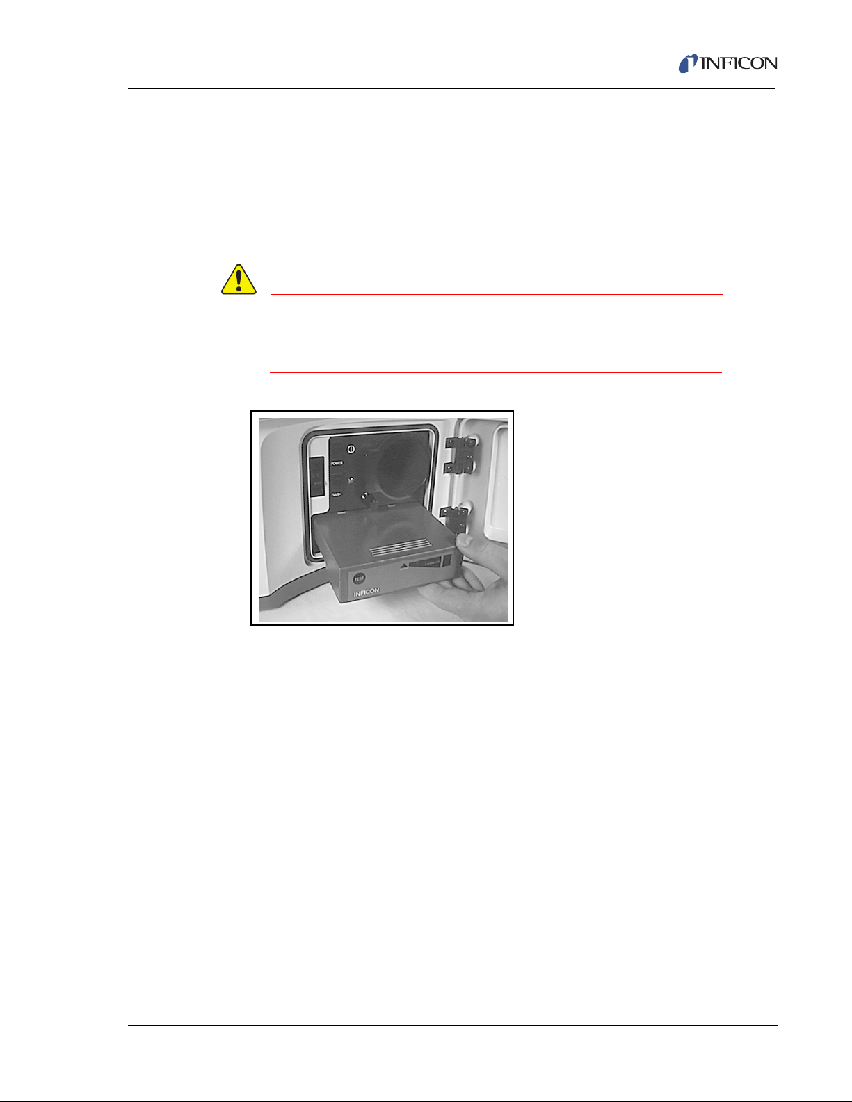
HAPSITE Smart Plus Operating Manual
CAUTION
10 If using the HSS in portable mode, a battery will need to be installed. Open the
front door of the HSS and insert a charged battery into the rectangular slot
below the round carrier gas slot. Make sure when inserting the battery that the
lettering is right-side up to insure proper orientation. When inserted correctly, it
will click into place and remain snug. After battery has been properly installed,
disconnect the AC/DC power supply. See Figure 2-28. (For further instructions
on battery installation see section 2.4.4 on page 2-10)
Do not open in a contaminated area. The HSS is not
sealed against moisture, debris or contamination with
the front door open.
Figure 2-28 Inserting the Battery into the HSS
2.8 Service Module
The Service Module is used to create a vacuum in the HAPSITE. It cannot be used
in a portable application.
IPN 074-472-P1C
2.8.1 Setting Up the Service Module
For additional information on the Service Module, refer to Chapter 15, Service
Module.
Required Components
RS-232 communication cable.
Power cord for Service Module.
Laptop with Plus IQ software installed.
When stored, the Service Module should have an aluminum plug placed on the top
opening. This plug is used to keep the Service Module free of moisture and debris.
2 - 19
Page 58

HAPSITE Smart Plus Operating Manual
NOTE: The aluminum storage plug is supplied with the Service Module. See
Figure 2-29.
Figure 2-29 Aluminum Storage Plug on Service Module
Covering the aluminum plug is a yellow plastic cover, which aids in protecting the
opening from foreign debris. See Figure 2-30. Remove the yellow cover before
proceeding, and store it in a safe location.
Figure 2-30 Yellow Plastic Protective Cover on Service Module
2 - 20
The Service Module requires a power cable and a RS-232 communications cable
to allow communication with the Laptop. Figure 2-31 shows the power cable
connected at the left back corner of the Service Module.
IPN 074-472-P1C
Page 59

HAPSITE Smart Plus Operating Manual
Figure 2-31 Power Cable Attached at Back Left of the Service Module
The RS-232 communication cable is shown in Figure 2-32.
Figure 2-32 RS-232 Communication Cable
To prepare the Service Module for use with the HAPSITE, the aluminum plug must
IPN 074-472-P1C
be removed. If the plug is not under vacuum, the plug can easily be removed. If
under vacuum, the plug will need to be removed using the following procedure:
NOTE: The Service Module is shipped under vacuum from the factory with this
plug in place.
Attach the RS-232 communications cable to the Service Module, as shown in
Figure 2-33.
2 - 21
Page 60

HAPSITE Smart Plus Operating Manual
Figure 2-33 RS-232 Communication Cable Attached to Back Right Side of Service Module
Attach the RS-232 cable to the Laptop computer, as shown in Figure 2-34.
Figure 2-34 RS-232 Communication Cable Attached to Laptop
2 - 22
Turn on the Power switch for the Service Module, located at the back right corner
of the Service Module (refer to Figure 2-31).
Turn on the Laptop and open the Plus IQ program.
IPN 074-472-P1C
Page 61

HAPSITE Smart Plus Operating Manual
WARNING
Figure 2-35 System Setup Screen with Service Module
NOTE: If the Service Module icon does not appear, the communications may need
to be configured. See section 8.6.3, Establishing Communication with the
Service Module, on page 8-20, for information on how to set up a COM port
for communicating with the Service Module.
Click on the Vent icon. The dialog shown in Figure 2-36 will appear to confirm the
venting of the Service Module.
Figure 2-36 Vent Service Module Confirm Window
Select Yes to vent the Service Module. A window will appear counting down a
fifteen-second delay while the vent procedure completes. Once completed, remove
the aluminum plug.
IPN 074-472-P1C
Next, clean any debris or dust from the Viton® o-ring using a lint-free wipe with
methanol. Wipe the top of the o-ring, following the contour to clean the entire top
exposed section. Avoid pushing dust or debris into the middle opening. Cleaning
will ensure a tight seal to the HAPSITE, allowing the system to maintain vacuum.
See Figure 2-37, which shows the o-ring being cleaned.
Wear gloves and safety glasses when handling methanol.
2 - 23
Page 62

HAPSITE Smart Plus Operating Manual
CAUTION
CAUTION
Figure 2-37 Cleaning the Service Module Rubber O-ring using a Lint-free Wipe
After cleaning the rubber o-ring, make sure there are no cuts on it. Also look for any
visible cracking of the o-ring. If the o-ring is damaged, the o-ring may need to be
replaced. Ensure the o-ring is completely seated in the grove.
2.8.2 Placing the HAPSITE on the Service Module
Never operate the HAPSITE on the Service Module in a
moving vehicle.
Remove the yellow plastic protective cover from the bottom of the HAPSITE. The
yellow cover is shown in Figure 2-38.
NOTE: Store the yellow cover in a clean, dry place, where it will be easily
accessible for later use. This protective cover keeps dust and debris out of
the HAPSITE manifold connection.
During decontamination of the HAPSITE, the yellow
protective cover must be installed.
IPN 074-472-P1C
2 - 24
Page 63

HAPSITE Smart Plus Operating Manual
Figure 2-38 Remove the Yellow Plastic Protective Cover on the Bottom of the HAPSITE
Figure 2-39 shows the yellow protective cover removed from the bottom of the
HAPSITE.
Figure 2-39 Yellow Plastic Protective Cover Removed from the Bottom of the HAPSITE
Carefully place the HAPSITE on top of the Service Module. The opening at the
bottom of the HAPSITE should be placed onto the opening on the Service Module.
Attach the Service Module to the HAPSITE using the black latch at each side of the
Service Module. Figure 2-40 shows the right side Service Module latch.
IPN 074-472-P1C
Figure 2-40 Service Module - Showing Latch on Right Side
Figure 2-41 shows the HAPSITE attached to the Service Module using the Service
Module latches.
2 - 25
Page 64

HAPSITE Smart Plus Operating Manual
CAUTION
NOTE: Black latches can be adjusted with the thumb screw to ensure proper
tension.
Figure 2-41 HAPSITE Attached to Service Module using Service Module Latches -
Left Side View
Continue by following the instructions in section 15.6, Starting Up HAPSITE on the
Service Module, on page 15-11.
Never attempt to move the Service Module when the
turbo pump is spinning. The Turbo Pump must be at 0 Hz
before moving or detaching the HAPSITE. Damage can
result if the HAPSITE is not properly detached.
2.8.3 Detaching the HAPSITE from the Service Module
Carefully follow the procedures starting with section 15.8, Detaching the HAPSITE,
on page 15-17 to detach the HAPSITE from the Service Module.
IPN 074-472-P1C
2 - 26
Page 65
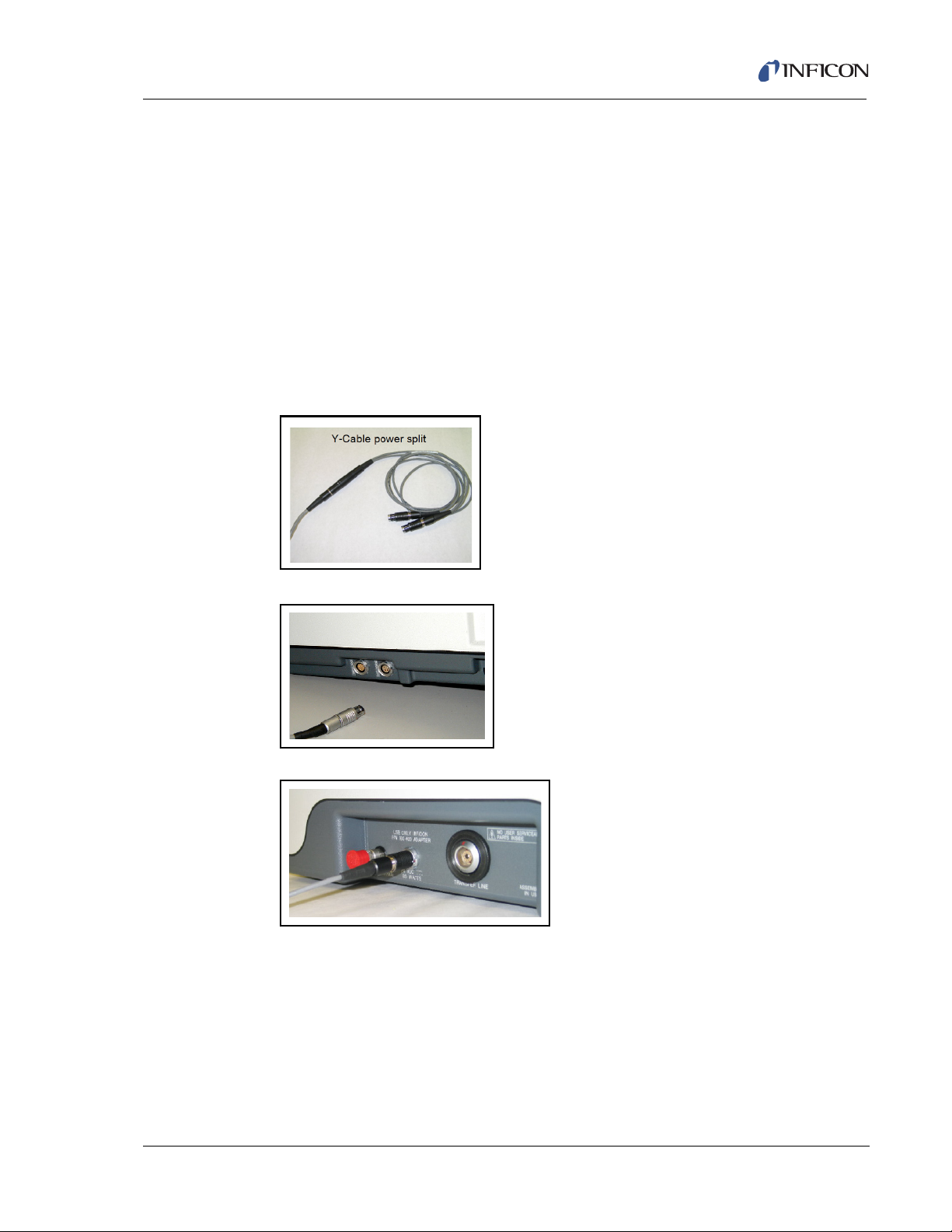
2.9 SituProbe
Use the following procedure to set up the SituProbe. For more SituProbe
information, see Chapter 14.
1 After verifying that the battery in the HAPSITE is charged, disconnect the AC
to DC HAPSITE Adapter power supply.
2 Remove the Probe.
3 Using a Y-Cable Power Splitter, connect the single connector end of the cable
to the AC to DC HAPSITE Adapter. Connect one of the split ends of the cable
to the left side of the HAPSITE and the other to the back of the SituProbe
accessory (IPN 932-220-G1). See Figure 2-42, Figure 2-43 and Figure 2-44.
Figure 2-42 Y- Cable for SituProbe
HAPSITE Smart Plus Operating Manual
Figure 2-43 Plugging Y-Cable Into HAPSITE
Figure 2-44 Plugging Y-Cable Into SituProbe
IPN 074-472-P1C
4 Properly align the labels on the foam insulation and Transfer Line. The end of
the insulation labeled in yellow THIS END TO HAPSITE should coincide with
the end of the Transfer Line labeled in yellow THIS END TO HAPSITE. See
Figure 2-23.
2 - 27
Page 66

HAPSITE Smart Plus Operating Manual
5 The white label THIS END TO ACCESSORY on the insulation should coincide
with the white label THIS END TO ACCESSORY on the Transfer Line. See
Figure 2-24. When alignment is correct, slide the insulation into place.
Figure 2-45 Accessory End of the Transfer Line
6 Install the Transfer Line between the HAPSITE and the SituProbe. First,
disconnect the Probe from the HAPSITE. Install the LEMO connector, which is
labeled, THIS END TO HAPSITE, in the HAPSITE connector. The opposite end
labeled, THIS END TO ACCESSORY, will connect to the rear of the SituProbe.
See Figure 2-46. Make sure the red dots on the Transfer Line connectors align
with the marks on the HAPSITE and SituProbe connectors.
Figure 2-46 Attaching the Transfer Line to the HAPSITE
IPN 074-472-P1C
2 - 28
Page 67
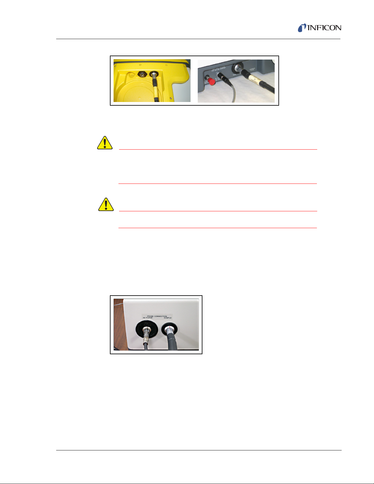
HAPSITE Smart Plus Operating Manual
CAUTION
WARNING
Figure 2-47 Plugging Transfer Line Into HAPSITE and SituProbe
7 Open the front panel door of the SituProbe accessory and insert a Nitrogen
canister into the canister opening.
Do not open in a contaminated area. The SituProbe is not
sealed against moisture, debris and contamination with
the front door open.
Nitrogen canisters and cylinders are under pressure.
8 OPTIONAL: Insert a charged battery into the SituProbe accessory battery slot.
The battery is not required when using the external AC to DC HAPSITE
Adapter.
9 Connect the Nitrogen purge and sample lines on the SituProbe purge head
(IPN 932-200-G1) onto the side of the SituProbe accessory. See Figure 2-48.
Figure 2-48 Connecting Purge Head
IPN 074-472-P1C
10 Power on the SituProbe accessory by using the toggle switch located inside the
front panel door. Close the front panel door before using the SituProbe.
11 If using a purge vessel, fill the vessel with 1L of water. Place the SituProbe
purge head into vessel. Sample will flow inward through the side bottom
opening and outward through the top side opening. See Figure 2-49.
2 - 29
Page 68
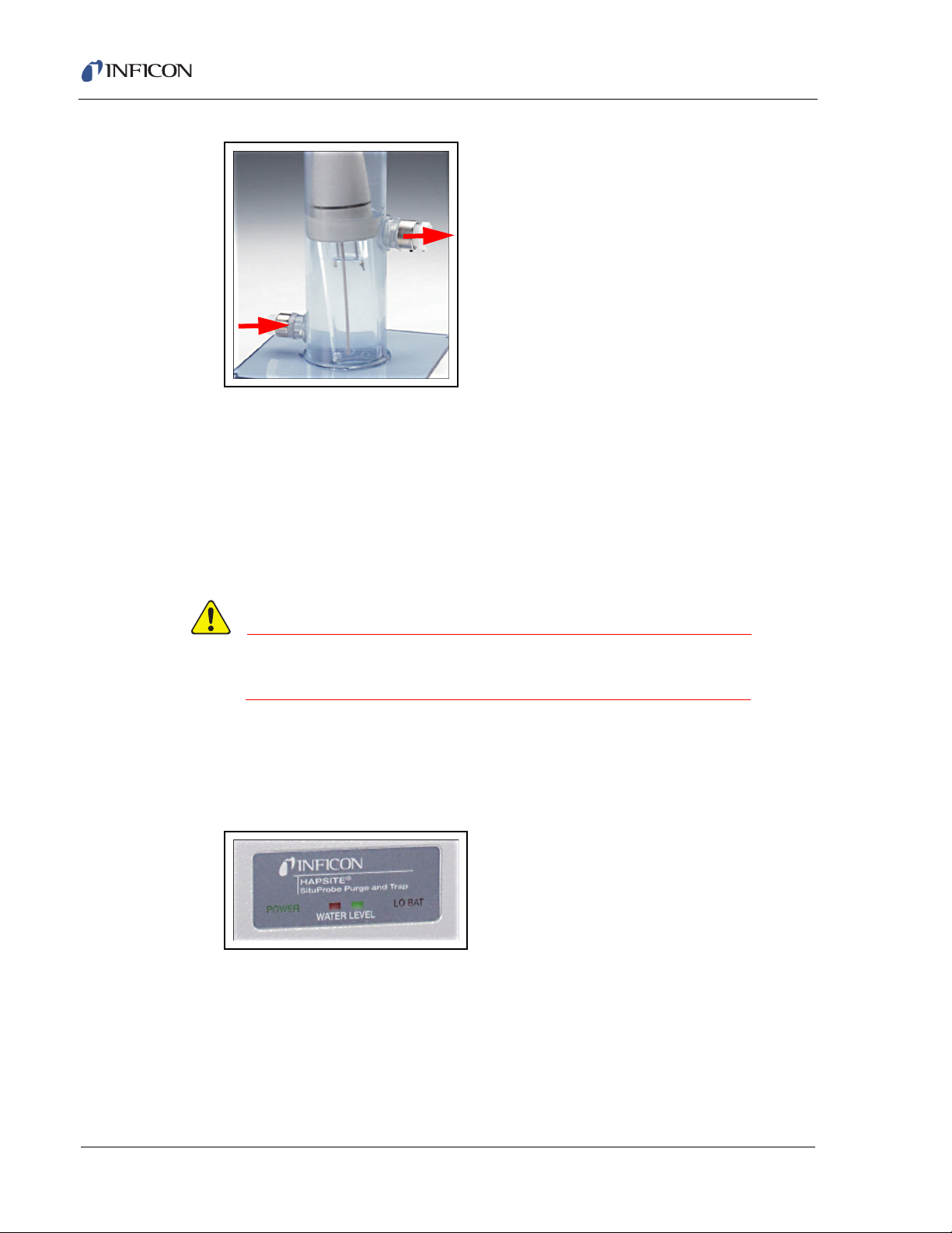
HAPSITE Smart Plus Operating Manual
CAUTION
Figure 2-49 Purge Vessel Water Flow Direction Shown
12 The purge vessel can also be used with the openings capped. In this option, fill
the vessel to the 1L mark with the water to be sampled. Place the purge head
into the vessel.
13 Alternately, place the SituProbe purge head into the water supply to sample.
NOTE: Minimum submersion depth is 5.5 inches (14 cm) and the maximum is
18 inches (45.7 cm).The depth should be measured from the bottom of
the purge head towards the electrodes.
Submersion greater than 18 inches (45.7 cm) could cause
liquid to enter the HAPSITE.
14 The SituProbe accessory (IPN 932-220-G1) displays water level conditions in
the purge head. Green signifies that the water level is in operating range. Red
signifies that the water level is too low. Red and green together signify that the
water level is too high. See Figure 2-50.
Figure 2-50 Water Level Indicator
IPN 074-472-P1C
2 - 30
Page 69
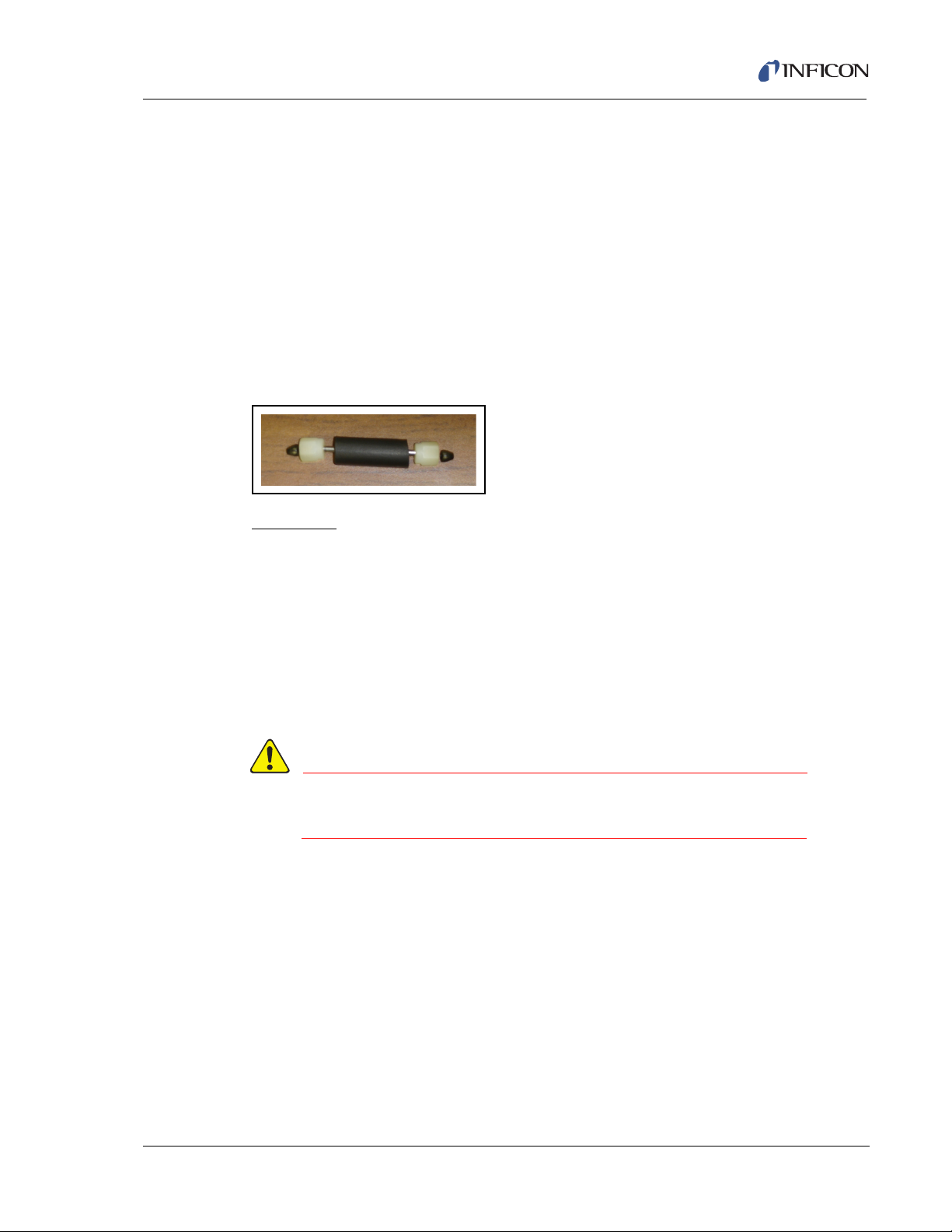
2.10 Sample Collection Modes
WARNING
The Sample Loop is used to detect chemicals in the low ppm to high ppb
concentration range. The Concentrators are used to detect chemicals in the low
ppb to high ppt concentration range. The following procedures are used to install
and remove the Sample Loop and the Concentrator.
2.10.1 Installing the Sample Loop
The Sample Loop is a hollow stainless steel tube. The sample volume is
approximately 200 µL. Black insulation covers the center of the Sample Loop. Each
end has a nut and a black, Vespel
Figure 2-51 Sample Loop
Procedure
HAPSITE Smart Plus Operating Manual
® ferrule assembly. See Figure 2-51.
1 See section 2.10.2, Removing the Sample Loop, on page 2-34 to remove the
currently installed Sample Loop or see section 2.10.4, Removing the
Concentrator, on page 2-41 to remove the Concentrator.
NOTE: There is not a specific orientation for the Sample Loop.
2 Make sure a ferrule is installed in each metal nut with the wide end of the cone
facing toward the center of the Sample Loop, as shown in Figure 2-51. The
ferrules are inserted into the threaded end of the nut.
The elbow fittings may be hot. Allow for these
components to cool before continuing.
IPN 074-472-P1C
3 While holding the ferrule and nut in place, insert one end of the Sample Loop
into the bottom elbow fitting.
4 Lift the top elbow fitting slightly, so that the top of the Sample Loop will fit
between the two fittings.
5 Press down on the top elbow. With your fingers, tighten the bottom nut until the
nut is finger tight. See Figure 2-52.
2 - 31
Page 70
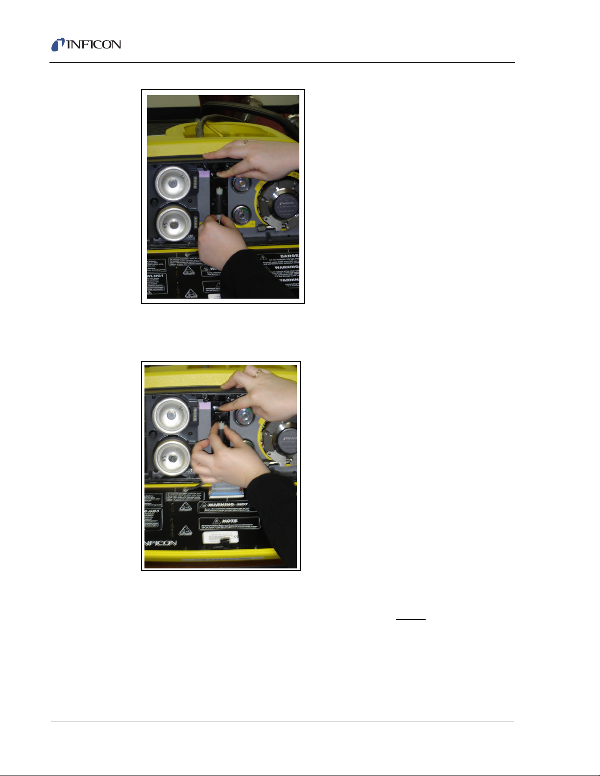
HAPSITE Smart Plus Operating Manual
Figure 2-52 Tightening the Bottom Nut
6 Continue pressing on the top elbow and tighten the top nut finger tight. See
Figure 2-53.
Figure 2-53 Tightening the Top Nut
7 Using the 7/16" open end wrench supplied with the HAPSITE, tighten both the
top and bottom nut approximately 1/8-1/4 of a turn. When pressure is released
from the top fitting, the elbow should not move. When gentle
upward pressure
IPN 074-472-P1C
2 - 32
Page 71
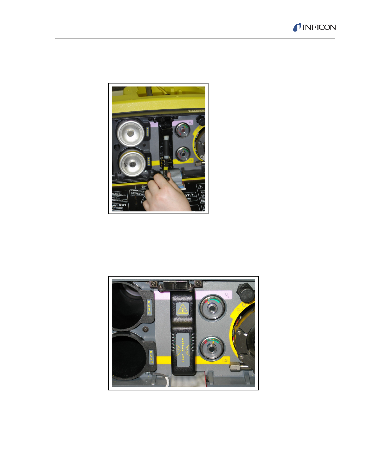
HAPSITE Smart Plus Operating Manual
is applied to the top elbow, the elbow should not slip on the Sample Loop. If the
elbow moves, the Loop is not properly seated. Reseat Loop and tighten slightly
more. See Figure 2-54.
Figure 2-54 Wrench tighten
8 Snap on the black cover labeled SAMPLE LOOP. The cover will fit snugly over
the Sample Loop. See Figure 2-55.
NOTE: If the cover does not easily fit over the Sample Loop, do not force it. Check
to ensure the Loop is correctly installed with the Loop fully seated into both
elbows and the nuts properly tightened for a secure fitting.
Figure 2-55 Sample Loop Cover Installed
IPN 074-472-P1C
2 - 33
Page 72
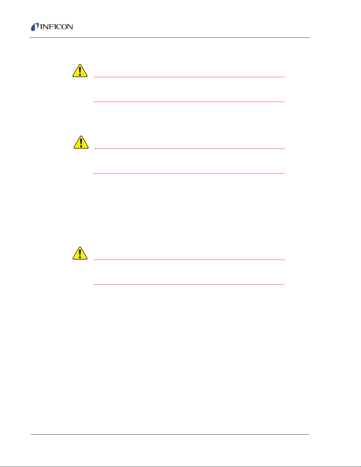
HAPSITE Smart Plus Operating Manual
CAUTION
WARNING
CAUTION
2.10.2 Removing the Sample Loop
To prevent contamination, only open front panel in a dry,
uncontaminated area.
1 Open the front panel of the HAPSITE and remove the black cover labeled
SAMPLE LOOP.
The elbow fittings, nuts and Sample Loop may be hot.
Allow for these components to cool before continuing.
2 Using the 7/16" open end wrench suppled by INFICON, loosen the nuts on the
top and bottom of the Sample Loop until it becomes free.
3 Remove the Sample Loop, being careful not to lose the ferrules on the top and
bottom. Store the Sample Loop in a safe place for future use.
2.10.3 Installing the Tri-Bed or Tenax Concentrator
To prevent contamination, only open front panel in a dry,
uncontaminated area.
1 Refer to section 2.10.2, Removing the Sample Loop, on page 2-34 to remove
the Sample Loop or see section 2.10.4, Removing the Concentrator, on page
2-41 to remove the currently installed concentrator.
2 Remove the Concentrator from the storage vial and unwrap. Make sure a
Te fl on
® ferrule is installed in each plastic nut with the wide end of the cone
facing toward the center of the Concentrator, as shown in Figure 2-56. The
ferrules are inserted into the threaded end of the nut.
NOTE: The Tri-Bed Concentrator is directional. The Tri-Bed Concentrator
must be installed with the smooth metal sleeve pointing down and the
grooved metal sleeve pointing up. See Figure 2-56.
IPN 074-472-P1C
2 - 34
Page 73
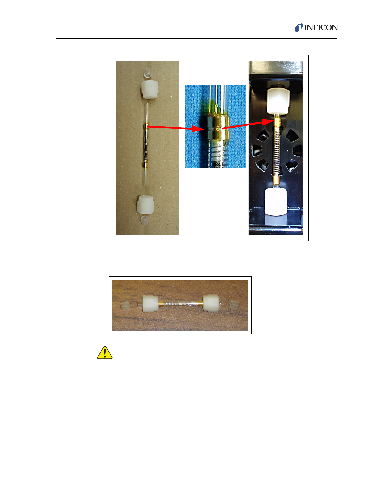
HAPSITE Smart Plus Operating Manual
WARNING
Grooved End
Pointing Up
Figure 2-56 Proper Tri-Bed Concentrator Orientation
NOTE: The Tenax Concentrator does not have a specific orientation. See
Figure 2-57.
Figure 2-57 Tenax Concentrator
IPN 074-472-P1C
The elbow fittings may be hot. Allow for these
components to cool before continuing.
3 For the Tri-Bed Concentrator: While holding the nut and ferrule in place,
carefully place the smooth metal sleeve end of the Tri-Bed Concentrator into
the lower elbow fitting.
2 - 35
Page 74

HAPSITE Smart Plus Operating Manual
3a For the Tenax Concentrator: While holding the nut and ferrule in place, carefully
place either end of the Concentrator into the lower elbow fitting. See Figure
2-58.
Figure 2-58 Placing Concentrator in Bottom Elbow
2 - 36
IPN 074-472-P1C
Page 75

HAPSITE Smart Plus Operating Manual
4 For the Tri-Bed Concentrator: Carefully lift up on the top elbow fitting and insert
the end of the Concentrator with the grooved metal sleeve into this fitting. See
Figure 2-59.
4a For the Tenax Concentrator: Carefully lift up on the top elbow fitting and insert
either end of the Concentrator into this fitting. See Figure 2-59.
Figure 2-59 Inserting the Top of the Concentrator
IPN 074-472-P1C
2 - 37
Page 76

HAPSITE Smart Plus Operating Manual
5 Keep the Concentrator aligned between the two elbow fittings while gently
pressing down on the top elbow fitting. See Figure 2-60.
Figure 2-60 Pressing Down on Elbow Assembly
6 While maintaining gentle pressure on the top elbow fitting, first finger-tighten
the bottom nut of the Concentrator. Then, proceed to finger-tighten the top nut.
See Figure 2-61.
Figure 2-61 Tightening the Top and Bottom Nut
IPN 074-472-P1C
2 - 38
Page 77

HAPSITE Smart Plus Operating Manual
WARNING
Excessive force and/or tightening can cause the fragile
glass to break!
7 When pressure is released from the top fitting, the elbow should not move.
When gentle
slip on the Concentrator. See Figure 2-62. If the elbow moves, the Concentrator
is not properly seated, loosen the Concentrator and repeat Step 3 on page 35
through Step 6 on page 38.
Figure 2-62 Checking for Movement
upward pressure is applied to the top elbow, the elbow should not
IPN 074-472-P1C
8 Place the black Concentrator Cover (see Figure 2-63) over the Concentrator
and elbow assembly. The cover should fit easily, excessive force is not required
if the Concentrator is properly installed.
2 - 39
Page 78

HAPSITE Smart Plus Operating Manual
WARNING
Figure 2-63 Installed Concentrator Cover
NOTE: If the cover does not easily fit over the Concentrator, do not force it on.
Check to ensure the Concentrator is correctly installed with the
Concentrator fully seated into both elbows and the nuts properly
tightened for a secure fitting.
NOTE: The Concentrator Cover contains two metal contacts that are
supported by Fiberglass. Inspect the contacts, prior to assembly, to be
sure the contacts are not bent or crimped. See Figure 2-64.
Use the proper Concentrator cover, which contains an
Electronic Circuit board, for the Smart Plus. Do not use
the old Concentrator cover from the HAPSITE Smart
Plus. If the old cover is used, the cover will overheat and
may become damaged.
Figure 2-64 Back of the New Concentrator Cover
IPN 074-472-P1C
2 - 40
Page 79

HAPSITE Smart Plus Operating Manual
WARNING
WARNING
Figure 2-65 Back of the Old Concentrator Cover
9 Close the front panel.
2.10.4 Removing the Concentrator
1 Open the front panel of the HAPSITE and remove the black cover labeled
CONCENTRATOR.
The elbow fittings, nuts and Concentrator may be hot.
Allow these components to cool before continuing.
Excessive force and/or tightening can cause the fragile
IPN 074-472-P1C
2 With fingers, loosen the nuts on the top and bottom of the Concentrator until the
3 Lift the top elbow. Gently lift and angle the Concentrator out of the fixture.
4 Remove the Concentrator from the bottom elbow, being careful not to lose the
glass to break!
it becomes free.
ferrules inside the nuts.
5 Store the Concentrator wrapped in tissue in its storage vial for future use.
2 - 41
Page 80
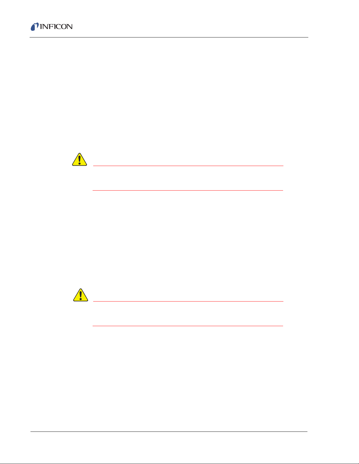
HAPSITE Smart Plus Operating Manual
CAUTION
WARNING
2.11 Probe Sampling Options and Attachments
To expand the sampling range of the HAPSITE, sample collecting bags can be
used and special VX / R-33 Conversion Tubes can be attached.
2.11.1 Probe Nut Assembly
The orientation of the ferrules in the probe nut is critical for attaching a bag sample
or VX / R-33 Conversion Tube.
1 Using a guide (golf tee, small screwdriver, plastic pen cap with pocket clip
extension), place the metal probe nut over the guide’s narrow end. The threads
on the nut should be facing up.
Be sure the guide is clean to prevent the introduction of
contaminants into the HAPSITE.
2 Place the small, back ferrule over the narrow end of the guide with the beveled
side facing up.
3 The cone-shaped ferrule should be placed over the bevel with the narrow end
facing up. See Figure 2-66.
4 Carefully remove the nut assembly from the narrow end of the guide. Gently tap
the nut so that the ferrules seat properly into the nut.
5 Thread the nut-ferrule assembly onto the probe.
6 Finger-tighten the nut-ferrule assembly into place.
Correct ferrule orientation is critical to avoid leaks of
hazardous or toxic material
IPN 074-472-P1C
2 - 42
Page 81

HAPSITE Smart Plus Operating Manual
WARNING
Narrow end of cone
pointed upwards
Beveled side of back
ferrule pointed upwards
Body of the probe nut
NOTE: Use a guide (such as a pen cap or sharpened
pencil) inside the opening of the nut to ensure correct
back ferrule orientation.
Figure 2-66 Diagram of Proper Ferrule Orientation in the Probe Nut
2.11.2 Attaching a Bag Sample
IPN 074-472-P1C
When samples are collected to be run later, various sampling bags can be used.
This procedure outlines the steps used to attach a Tedlar® Bag.
Be sure the bag valve remains closed when it is not
attached to the probe. Make sure there is an exhaust tube
attached to the exhaust port on the HAPSITE. Be sure the
exhaust vents to a safe area.
1 Before attaching a Tedlar Bag to the Probe, refer to section 2.11.1, Probe Nut
Assembly, on page 2-42 to ensure proper ferrule orientation in the probe nut.
2 Prepare the Tedlar Bag sample. Avoid filling bag more than 80% full. Be sure
the white valve is closed on the Tedlar bag.
3 Loosen the nut on the probe by turning the nut counter-clockwise up to two
complete revolutions.
4 Guide the white cylindrical stem of the bag valve assembly into the opening of
the probe nut. Firmly push the stem into the probe nut. Two cylinder "clicks" are
usually felt before the bag is properly seated into the probe nut.
5 Finger tighten the probe nut by turning the nut clockwise.
6 When it is time for the HAPSITE to collect the sample, open the Tedlar Bag by
turning the valve one complete counter-clockwise revolution.
2 - 43
Page 82
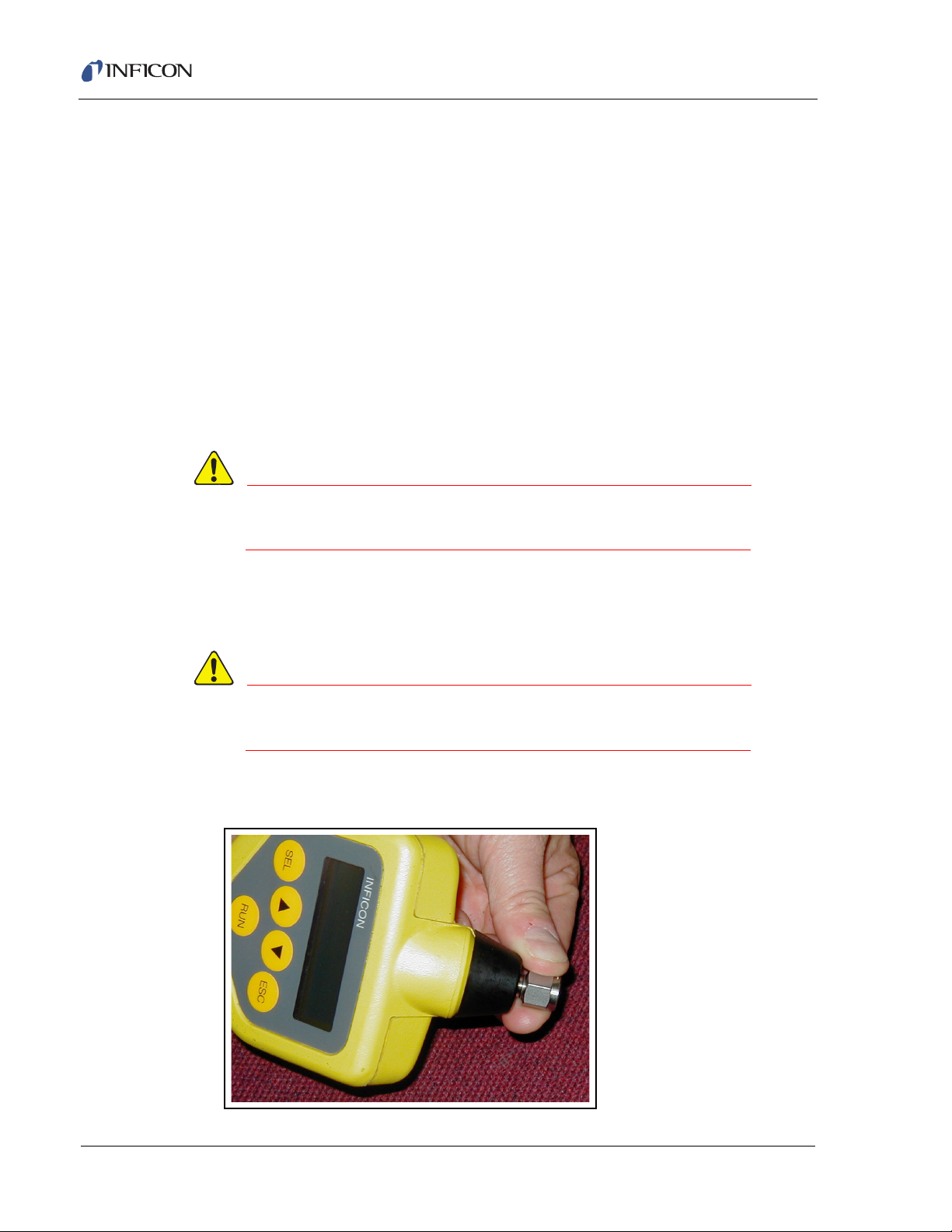
HAPSITE Smart Plus Operating Manual
WARNING
WARNING
2.11.3 VX / R-33 Conversion Tube
This procedure describes the steps required to prepare the HAPSITE to sample for
VX or R-33 using the Conversion Tube. To detect VX or R-33, you must insert the
Conversion tube following the guidelines below.
The process of detecting VX or R-33 on the HAPSITE requires the conversion of
VX or R-33 (high boiling point chemicals) to the G analog. The VX or R-33 molecule
is broken at the sulfur bond when it comes in contact with a silver fluoride pad. The
result is the formation of a volatile chemical ethyl methyl phospho no fluoridate in
the case of VX, or isobutyl methyl phospho no fluoridate in the case of R-33. These
compounds are detected by the HAPSITE as VX-G or R-33-G.
NOTE: Theoretically, other G agents can be detected with the VX conversion pad
in place. However, if other G agents are suspected, the sample should also
be run without the conversion tube in place.
Sulfur mustard cannot be detected with the conversion
tube in place.
2.11.3.1 VX / R-33 Conversion Tube Installation
1 Refer to section 2.11.1, Probe Nut Assembly, on page 2-42 to ensure proper
ferrule orientation in the probe nut.
Correct ferrule placement is critical to ensure a leak-free
fit around the conversion tube.
2 Loosen the nut on the end of the probe approximately 1/4 to 1/2 of a turn. See
Figure 2-67.
Figure 2-67 Loosening the Nut
IPN 074-472-P1C
2 - 44
Page 83
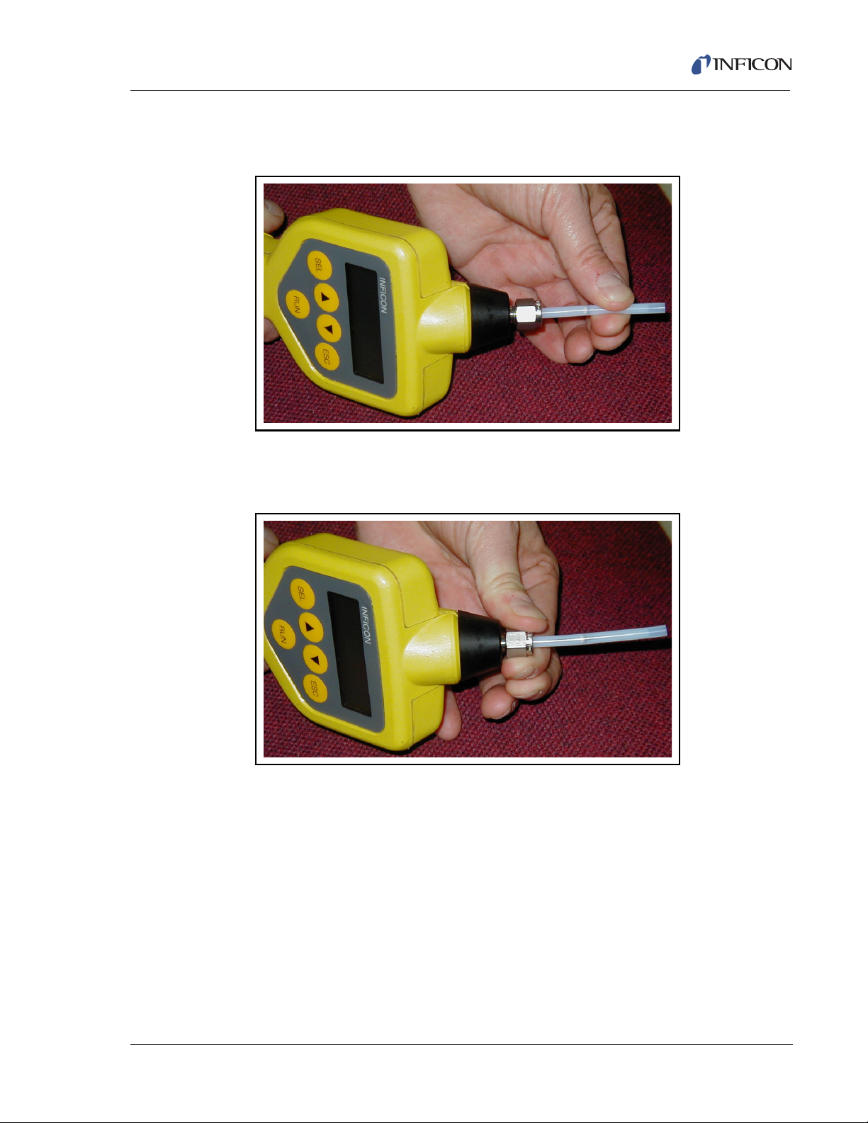
HAPSITE Smart Plus Operating Manual
3 Insert either end of the VX / R-33 Conversion Tube into the nut. Make sure the
tube is firmly seated into the front ferrule. See Figure 2-68.
Figure 2-68 Inserting the Tube
4 Finger tighten the nut. Pull gently on the conversion tube, it should be held
firmly in place. See Figure 2-69.
Figure 2-69 Tightening the Nut
IPN 074-472-P1C
2 - 45
Page 84

HAPSITE Smart Plus Operating Manual
WARNING
2.11.3.2 VX / R-33 Conversion Tube Removal
If conversion tube has been exposed take proper
precautions and wear appropriate Personal Protective
Equipment (PPE). PPE guidelines can be found in the
chemical’s MSDS. Dispose of the conversion tube
according to local regulations if it has been exposed.
1 Loosen the nut 1/4 to 1/2 of a turn.
2 Gently pull the VX / R-33 Conversion Tube out of the probe.
3 Finger tighten the nut.
2 - 46
IPN 074-472-P1C
Page 85
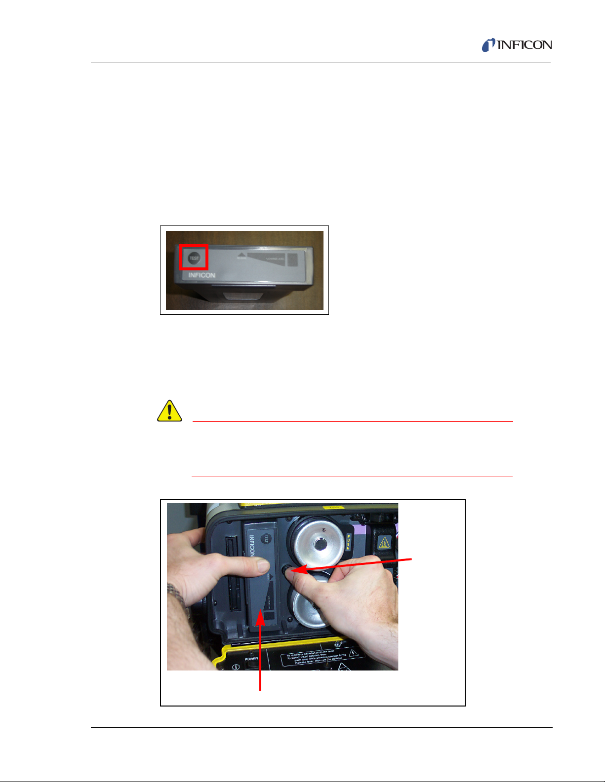
2.12 Batteries
CAUTION
Battery
Release
Button
Battery
The battery provides power to the HAPSITE to allow portability. Under optimum
conditions, the battery has a 2 to 3 hour life.
NOTE: To test a battery, push on the TEST button on the end of the battery. In the
elongated triangle, green lighted numbers will appear. The highest
illuminated number indicates the percentage of battery power left. The
percentage of remaining battery charge is reported in 20% increments.
See Figure 2-70.
NOTE: If OVER is illuminated, the battery is fully charged.
Figure 2-70 Battery Test Button and Charger Indicator
2.12.1 How to Remove a Battery
The black round button to the right of the battery is the battery release button. Two
clips hold the battery in the battery compartment. See Figure 2-71. Firmly push in
on the battery while simultaneously pressing and holding the battery release
button. As the clips release, pull the battery out.
HAPSITE Smart Plus Operating Manual
Do not expose the battery compartment to rain or other
foreign material. Do not open the compartment in a
contaminated or wet area.
Figure 2-71 Battery Release Button
IPN 074-472-P1C
2 - 47
Page 86
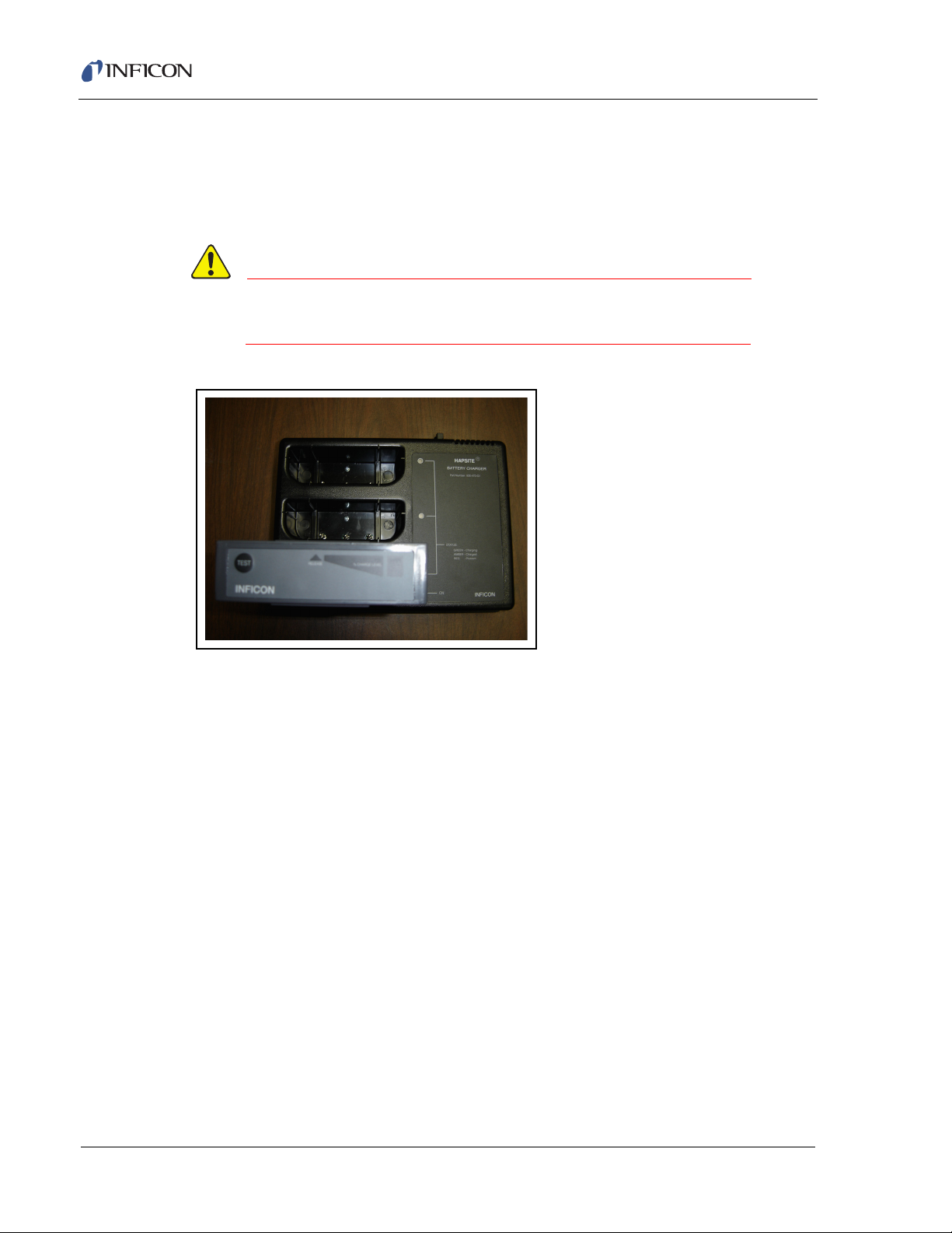
HAPSITE Smart Plus Operating Manual
CAUTION
2.12.2 Battery Charger
The auxiliary Battery Charger (part number 930-470-G1—see Figure 2-72)
charges up to three HAPSITE batteries in 15 hours or less. It operates using AC
power.
The battery charger is not sealed against moisture,
debris, or contamination.
Figure 2-72 Battery Charger
The Battery Charger operates from a range of nominal AC voltages from 100 to
230 V. It will continue to operate without internal damage at a voltage as low as
90 V and as high as 253 V. The frequency can be from 50 to 60 Hz. The Battery
Charger draws 120 W when fully loaded.
The AC power connects to the Battery Charger through a Type IEC 320 male plug,
a two-wire grounded connector rated for the full range of voltages. The connector
is recessed at the rear right-hand side of the Battery Charger and incorporates a
pair of fuses.
The Battery Charger is designed for indoor use at ambient temperatures from 5 °C
to 35 °C (41 °F to 95 °F). The Battery Charger is not designed for exposure to
contaminants since decontamination is not possible.
IPN 074-472-P1C
2 - 48
Page 87
HAPSITE Smart Plus Operating Manual
CAUTION
CAUTION
2.12.2.1 Battery Charger Components
The Battery Charger is shipped with a power cord and spare fuses.
2.12.2.2 Battery Charger Connections and Startup
Plug the power cord into the connector at the right rear of the Battery Charger. Then
plug into a grounded outlet. The ON light will illuminate. (The Battery Charger does
not have a power switch.)
As the Battery Charger performs a self-test, all the indicators will first turn amber.
Secondly, all receptacles that do not contain batteries will turn green. If a receptacle
contains a battery, it will turn red. Finally, all lights except for the ON indicator will
extinguish. No further warm-up is required; it is ready to charge batteries.
2.12.2.3 Loading the Battery Charger
The Battery Charger receptacles are identical and batteries in any state of charge
can be connected. Place Battery to be charged in one of the charging receptacles.
The respective indicator will illuminate green and charging will commence
immediately.
Do not use excessive force when placing the battery in
the battery charger.
Do not charge batteries in a moving vehicle.
IPN 074-472-P1C
2 - 49
Page 88

HAPSITE Smart Plus Operating Manual
2.12.2.4 Understanding the Battery Charger Indicators
Each battery receptacle is associated with an indicator light which can be
illuminated in any of three colors.
Green. . . . . . . . . . . . . . . . . . . . . . . . The battery is being charged. This will
continue for 15 hours or less. If a battery with
a severely depleted charge is inserted, the
green light will flash. If it flashes for more than
10 minutes, the battery will not accept a
charge and should be replaced. The actual
state of the battery charge can be assessed
by using the TEST button on the battery.
Amber . . . . . . . . . . . . . . . . . . . . . . . The battery is fully charged. The rate of
charge has been reduced to a maintenance
level. The battery can be left this way
indefinitely.
Red . . . . . . . . . . . . . . . . . . . . . . . . . The receptacle (or the battery, if one is
installed) has a problem. A flashing red light
indicates that communication with the battery
is unsuccessful.
Off . . . . . . . . . . . . . . . . . . . . . . . . . . The receptacle is ready to charge a battery. If
the indicator remains extinguished when a
battery is inserted, the battery is severely
depleted. In this case, leave the battery in the
receptacle and unplug the power cord.
Reconnect the power cord and the battery
will start to charge.
IPN 074-472-P1C
2 - 50
Page 89
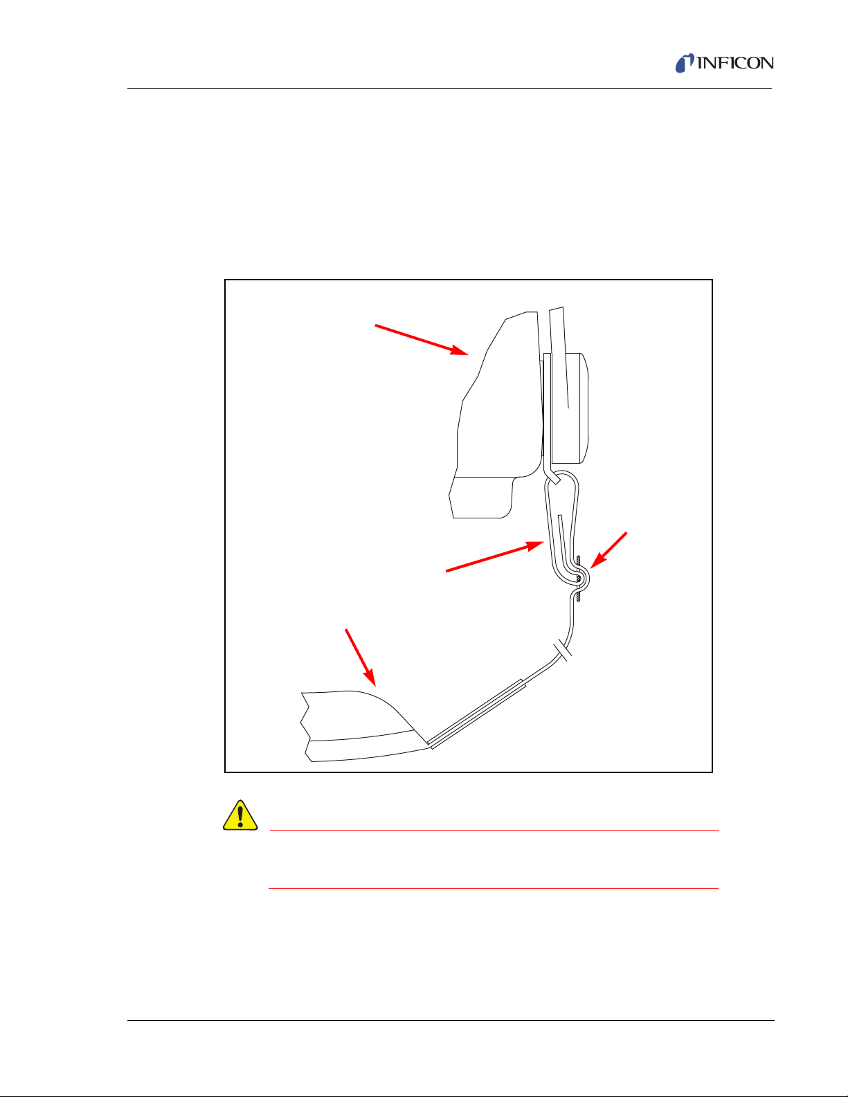
HAPSITE Smart Plus Operating Manual
WARNING
HAPSITE
Or Sampling Accessory
Strap must be attached
to HAPSITE or Sampling
Accessory as shown.
Strap Eyelet
Strap
2.13 Portable Accessories
Portability is an important HAPSITE feature. The following accessories facilitate
using the HAPSITE in the field.
2.13.1 HAPSITE and Headspace Sampling System Strap
Attach the HAPSITE and Headspace Sampling System straps as illustrated below
in Figure 2-73.
Figure 2-73 Attaching the HAPSITE Strap
IPN 074-472-P1C
Improper connection of the strap increases the risk of
dropping the HAPSITE and/or bodily injury
2 - 51
Page 90

HAPSITE Smart Plus Operating Manual
WARNING
2.13.2 HAPSITE Backpack
The backpack is a light weight, high quality hiker’s backpack. It has been modified
to securely mount the HAPSITE.
2.13.2.1 Adjustment of the Backpack
To adjust the backpack, proceed as follows.
1 Put on the empty backpack.
2 Tighten the hip belt.
3 Arrange the backpack so that:
The frame’s S-curve matches the curve of your back.
The hip belt rests on your hip bones.
The shoulder straps come from the frame at a slight downward angle over
your shoulders.
4 Note the height and shoulder strap adjustments that need to be made to
achieve a proper fit.
NOTE: Use a mirror to visually check the fit.
5 Take off the backpack.
6 If a height adjustment is needed, use the straps and plastic connectors on the
back of the backpack to move the hip belt up or down.
7 If the spacing between the shoulder straps needs adjustment, loosen or tighten
the straps located on the back of the backpack.
8 Try on the empty pack again. Repeat as necessary to achieve a proper fit.
9 Release the locks on the two stainless steel buckles.
10 Mount the HAPSITE on the backpack.
11 Correct adjustment of the tension of the buckles permits them to slide slightly
on the HAPSITE attachment points.
If the HAPSITE is not properly secured to the backpack,
the HAPSITE may fall or move unexpectedly which may
result in bodily injury to the user.
IPN 074-472-P1C
2 - 52
12 With the HAPSITE securely clipped to the backpack, put on the backpack.
13 Tighten the hip belt and shoulder straps.
14 The weight should be carried by your hips, with the shoulder straps steadying
the load.
Page 91

HAPSITE Smart Plus Operating Manual
CAUTION
WARNING
“L”
Battery
Power
Connector
Connector
2.13.2.2 Care of the Backpack
Avoid exposing the backpack to solvents and other active chemicals.
Avoid storing the backpack in direct sunlight.
Wash the backpack as necessary with water and mild soap.
Do not store the backpack with the fabric in contact with
concrete. The moisture and chemicals in concrete can
weaken nylon.
2.14 Hot Swap Cable (IPN 930-246-G1)
The Hot Swap Cable is used to provide an external power source for the HAPSITE.
When connected between an external battery and the 24 V(dc) power port on the
HAPSITE, the Hot Swap Cable permits changing the internal battery without the
loss of power to the HAPSITE.
IPN 074-472-P1C
2.14.1 Connecting the Hot Swap Cable
Do not use the hot swap cable in the rain.
1 Plug the "L" connector into the back of a charged battery. See Figure 2-74.
Figure 2-74 Hot Swap Cable Components
2 - 53
Page 92

HAPSITE Smart Plus Operating Manual
WARNING - Risk Of Electric Shock
WARNING - Risk Of Electric Shock
CAUTION
HAPSITE
24 V(dc)
Power
Port
Do not use if the "L" connector is broken.
Connect the Hot Swap Cable "L" connector to the battery
first. Then, plug the power connector into the HAPSITE
24 V(dc) power port.
2 Plug the power connector into the 24 V(dc) power port on the HAPSITE. The
depleted internal battery can now be replaced. After replacing the internal
battery, disconnect the Hot Swap Cable. See Figure 2-75.
Do not open the HAPSITE front panel in a contaminated
or wet environment.
Figure 2-75 Power Connector
IPN 074-472-P1C
2 - 54
Page 93

2.14.2 Storing the Hot Swap Cable
The Hot Swap Cable and Battery have exposed electrical connections. Protect the
connections from moisture or contaminated environments by storing the battery
and cable connection in a protective plastic bag. See Figure 2-76.
Figure 2-76 Storing
HAPSITE Smart Plus Operating Manual
2.14.3 Use as an Additional Battery Source
Attach the Battery to the HAPSITE via the Hot Swap Cable when the front panel
shows the level of charge on the internal battery is
additional battery source.
IPN 074-472-P1C
20%. This will provide an
2 - 55
Page 94

HAPSITE Smart Plus Operating Manual
This page is intentionally blank.
2 - 56
IPN 074-472-P1C
Page 95

HAPSITE Smart Plus Operating Manual
Operating HAPSITE in Portable Mode
3.1 Starting the HAPSITE in Portable Mode
Portable Mode refers to using the HAPSITE without the Laptop computer.
Required Materials
HAPSITE (Analytical Module)
Internal Standard Gas Canister
Carrier Gas Canister
Charged Battery
AC to DC Power Converter Power Supply
Probe
Chapter 3
Procedure
1 Assemble the HAPSITE as shown in Section 2.2, Basic Assembly, on page 2-5.
2 Press the POWER button on the front panel. The word POWER will illuminate.
Powering on the HAPSITE takes one (1) to two (2) minutes. See Figure 3-1.
Figure 3-1 The Power Switch
IPN 074-472-P1C
NOTE: Power on the HAPSITE while connected to AC power. Using battery
power to turn on and heat the HAPSITE will consume over 40% of the
battery’s charge.
3 The HAPSITE will boot in approximately one minute and will sense which
sample configuration (i.e., concentrator) has been installed. It will begin to
prepare the default method for this sample configuration.
4 The HAPSITE will begin to prepare various components. These components
include heating the HAPSITE and accessory heaters, running AutoTune (see
Step 8 on page 3-3), powering the NEG, and if necessary, running concentrator
cleanout.
3 - 1
Page 96
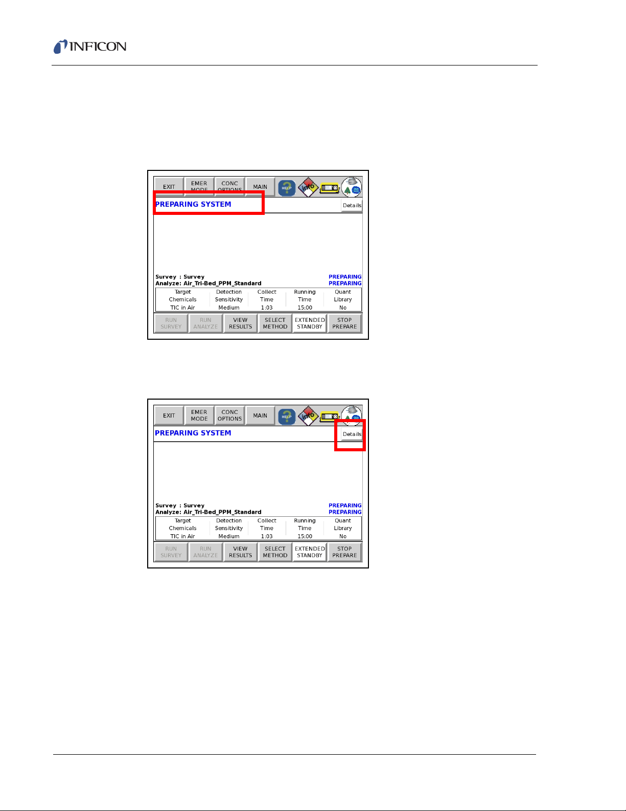
HAPSITE Smart Plus Operating Manual
5 During the preparation period, the front panel will display the PREPARING
SYSTEM message. Depending upon the chosen default method, this screen
may show PREPARING ANALYZE or PREPARING SURVEY. This message
will occur when the methods have different temperature setpoints. See Figure
3-2.
Figure 3-2 Front Panel Preparing System
6 To view the preparation details’ progress, touch the Details button. See Figure
3-3.
Figure 3-3 Details Button
IPN 074-472-P1C
3 - 2
Page 97
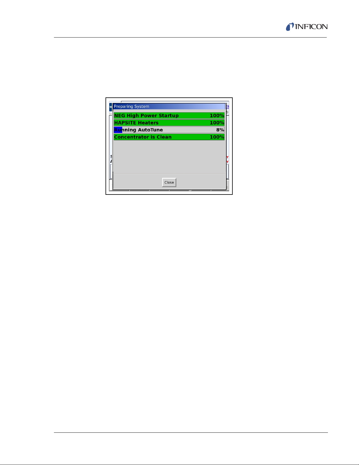
HAPSITE Smart Plus Operating Manual
7 The progress of the preparation is shown by a bar graph. If a component is in
the process of being prepared, it will be shown in blue. When a component is
ready, it will be shown in green. If a component is going to be prepared, but the
preparation process has not started, it will be shown in yellow. If the system is
not ready, the items that need to be prepared will be shown in red. Figure 3-4.
Figure 3-4 Preparation Bar Graph
8 When the heating sequence is completed, the software will check the mass
spectrometer tune and automatically make any necessary adjustments. The
automatic tune adjustment is called AutoTune. If AutoTune fails, see Section
6.4, Manual Tune Settings and Controls, on page 6-7.
9 As part of the preparation, a concentrator cleanout will be run when the
concentrator is installed. This cleanout will heat the concentrator to 180
remove residue. The cleanout will occur when the unit has been turned on,
taken out of Extended Standby, the concentrator has been changed or the
concentrator has been saturated.
NOTE: If a concentrator cleanout is not desired due to an emergency, see for
Emergency Mode (EMER MODE) instructions. See Section 3.1.1,
Emergency Mode (EMER MODE), on page 3-6.
IPN 074-472-P1C
NOTE: A concentrator cleanout can also be skipped, although skipping the
concentrator cleanout is not recommended and may lead to poor
results. See Section 3.1.2, Concentrator Options (CONC OPTIONS),
on page 3-8.
°C to
10 Hold the probe in a clean environment for the duration of the cleanout. If the
concentrator cleanout is not successful, see Section 3.1.3, Concentrator
Cleanout Failure, on page 3-11.
3 - 3
Page 98
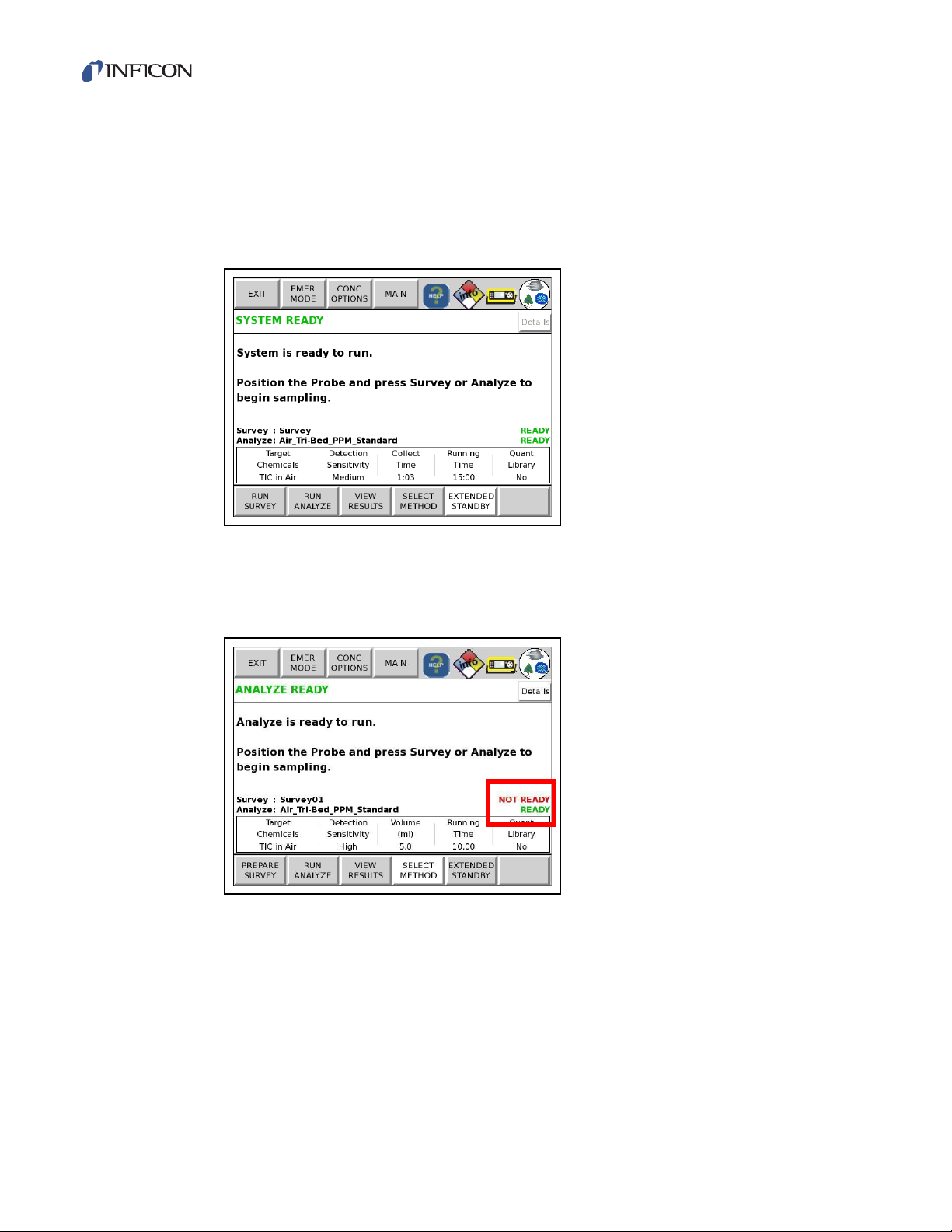
HAPSITE Smart Plus Operating Manual
11 When the HAPSITE is ready to run samples, a green SYSTEM READY,
SURVEY READY or ANALYZE READY message will be displayed. See Figure
3-5.
NOTE: The HAPSITE takes about twenty minutes to complete the preparation
sequence from a cold start.
Figure 3-5 System Ready
NOTE: If the methods are at different temperature setpoints, the method that
is ready to run will have a green READY message next to the method
name. See Figure 3-6.
Figure 3-6 Ready Message
IPN 074-472-P1C
3 - 4
Page 99
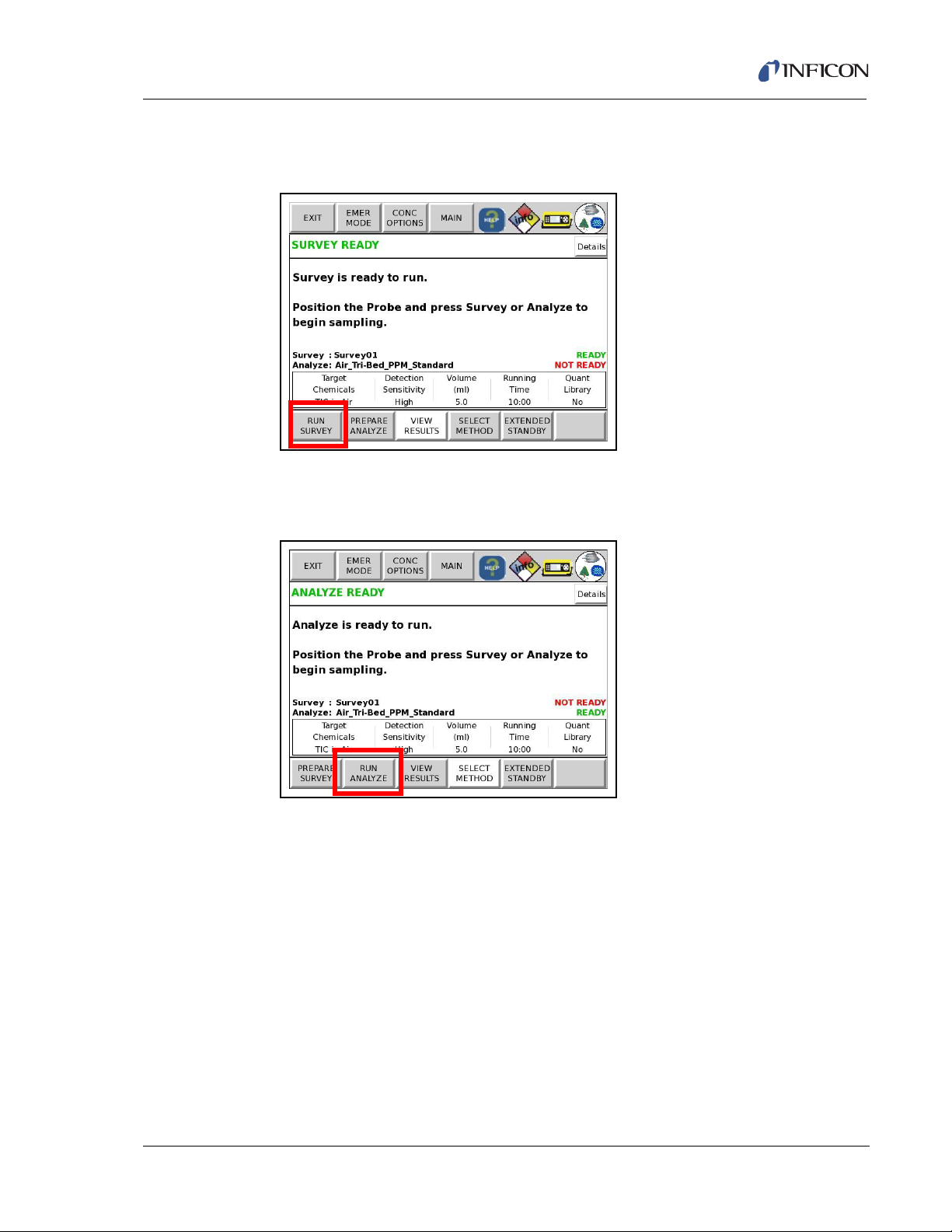
HAPSITE Smart Plus Operating Manual
12 If SURVEY READY is displayed, touch RUN SURVEY or push SURVEY RUN.
See Figure 3-7
Figure 3-7 Survey Ready
13 If ANALYZE READY is displayed, touch RUN ANALYZE or push ANALYZE
RUN. See Figure 3-8.
Figure 3-8 Analyze Ready
NOTE: If the system is preparing a SURVEY run and an ANALYZE method is
IPN 074-472-P1C
desired, touch the STOP PREPARE button. Then, touch the
PREPARE ANALYZE button. Likewise, if an ANALYZE method is
being prepared and a SURVEY is desired, touch STOP PREPARE,
followed by the PREPARE SURVEY button.
3 - 5
Page 100

HAPSITE Smart Plus Operating Manual
3.1.1 Emergency Mode (EMER MODE)
In an emergency, the concentrator cleanout can be bypassed to allow for faster
startup. This is not recommended for everyday use. To place the system into
Emergency Mode:
1 Touch EMER MODE while the PREPARING SYSTEM message is displayed.
See Figure 3-9.
Figure 3-9 Emergency Mode
2 Alternately, use the arrow keys to highlight the EMER MODE button and push
OK SEL. See Figure 3-10.
Figure 3-10 Arrow Keys
IPN 074-472-P1C
3 - 6
 Loading...