

Page 1
OPERATING MANUAL
Guardian
Co-Deposition Controller
IPN 074-517-P1D
™
Page 2

Page 3

OPERATING MANUAL
www.inficon.com reachus@inficon.com
©2012 INFICON
®
Guardian
Co-Deposition Controller
IPN 074-517-P1D
™
Page 4

Trademarks
The trademarks of the products mentioned in this manual are held by the companies that
produce them.
ConFlat® is a registered trademark of Varian Corporation.
Guardian™ is a trademark of INFICON GmbH.
LabVIEW™ is a trademark of National Instruments
Windows®, Access®, Excel® and AxtiveX® are registered trademarks of Microsoft Corporation.
Wonderware® is a registered trademark of Invensys plc
All other brand and product names are trademarks or registered trademarks of their respective companies.
Disclaimer
The information contained in this manual is believed to be accurate and reliable. However, INFICON assumes
no responsibility for its use and shall not be liable for any special, incidental, or consequential damages related
to the use of this product.
Due to our continuing program of product improvements, specifications are subject to change without notice.
Copyright
©2012 All rights reserved.
Reproduction or adaptation of any part of this document without permission is unlawful.
Page 5

DECLARATION
OF
CONFORMITY
This is to certify that this equipment, designed and manufactured by:
INFICON Inc.
Two Technology Place
East Syracuse, NY 13057
USA
meets the essential safety requirements of the European Union and is placed on the market accordingly. It has
been constructed in accordance with good engineering practice in safety matters in force in the Community and
does not endanger the safety of persons, domestic animals or property when properly installed and maintained and
used in applications for which it was made.
In addition, this is to certify that this equipment has also been designed and manufactured, having regard to the
state of the art, to ensure complies with the Protection Requirements of EMC directive 2004/108/EC.
A Technical Documentation File is also available for review by competent authorities and will be maintained for a
period of ten years after the date on which the equipment was last manufactured. In additional to this file,
technical, installation, maintenance and application information concerning this equipment can also be found in the
Operating Manual(s) for this product or product family.
Equipment Description: EIES Guardian (including all options).
Applicable Directives: 2006/95/EC (LVD)
2004/108/EC (General EMC)
2002/95/EC (RoHS)
Applicable Standards:
Safety: EN 61010-1:2001
Emissions: EN 61326-1:1997/A1: 1998/A2: 2001 (Radiated & Conducted Emissions)
Class A: Emissions per Table 3
(EMC – Measurement, Control & Laboratory Equipment)
Immunity: EN 61326-1:1997/A1: 1998/A2: 2001 (General EMC)
Class A: Immunity per Table A1
(EMC – Measurement, Control & Laboratory Equipment)
Page 6

CE Implementation Date: May 2008 (Updated May 2010)
Authorized Representative: Steve Schill
Thin Film Business Manager
INFICON Inc.
ANY QUESTIONS RELATIVE TO THIS DECLARATION OR TO THE SAFETY OF INFICON'S
PRODUCTS SHOULD BE DIRECTED, IN WRITING, TO THE VICE-PRESIDENT OF
OPERATIONS AT THE ABOVE ADDRESS.
Revised 5/2010
Page 7

Warranty
WARRANTY AND LIABILITY - LIMITATION: Seller warrants the products
manufactured by it, or by an affiliated company and sold by it, and described on
the reverse hereof, to be, for the period of warranty coverage specified below, free
from defects of materials or workmanship under normal proper use and service.
The period of warranty coverage is specified for the respective products in the
respective Seller instruction manuals for those products but shall not be less than
two (2) years from the date of shipment thereof by Seller. Seller's liability under
this warranty is limited to such of the above products or parts thereof as are
returned, transportation prepaid, to Seller's plant, not later than thirty (30) days
after the expiration of the period of warranty coverage in respect thereof and are
found by Seller's examination to have failed to function properly because of
defective workmanship or materials and not because of improper installation or
misuse and is limited to, at Seller's election, either (a) repairing and returning the
product or part thereof, or (b) furnishing a replacement product or part thereof,
transportation prepaid by Seller in either case. In the event Buyer discovers or
learns that a product does not conform to warranty, Buyer shall immediately notify
Seller in writing of such non-conformity, specifying in reasonable detail the nature
of such non-conformity. If Seller is not provided with such written notification,
Seller shall not be liable for any further damages which could have been avoided if
Seller had been provided with immediate written notification.
THIS WARRANTY IS MADE AND ACCEPTED IN LIEU OF ALL OTHER
WARRANTIES, EXPRESS OR IMPLIED, WHETHER OF MERCHANTABILITY OR
OF FITNESS FOR A PARTICULAR PURPOSE OR OTHERWISE, AS BUYER'S
EXCLUSIVE REMEDY FOR ANY DEFECTS IN THE PRODUCTS TO BE SOLD
HEREUNDER. All other obligations and liabilities of Seller, whether in contract or
tort (including negligence) or otherwise, are expressly EXCLUDED. In no event
shall Seller be liable for any costs, expenses or damages, whether direct or
indirect, special, incidental, consequential, or other, on any claim of any defective
product, in excess of the price paid by Buyer for the product plus return
transportation charges prepaid.
No warranty is made by Seller of any Seller product which has been installed,
used or operated contrary to Seller's written instruction manual or which has been
subjected to misuse, negligence or accident or has been repaired or altered by
anyone other than Seller or which has been used in a manner or for a purpose for
which the Seller product was not designed nor against any defects due to plans or
instructions supplied to Seller by or for Buyer.
This manual is intended for private use by INFICON® Inc. and its customers.
Contact INFICON before reproducing its contents.
NOTE: These instructions do not provide for every contingency that may arise in
connection with the installation, operation or maintenance of this equipment.
Should you require further assistance, please contact INFICON.
www.inficon.com reachus@inficon.com
Page 8

Page 9

Chapter 1
1.1 Introduction. . . . . . . . . . . . . . . . . . . . . . . . . . . . . . . . . . . . . . . . . . . . . . . . . . 1-1
1.2 EIES Controller. . . . . . . . . . . . . . . . . . . . . . . . . . . . . . . . . . . . . . . . . . . . . . .1-2
1.3 EIES Sensor. . . . . . . . . . . . . . . . . . . . . . . . . . . . . . . . . . . . . . . . . . . . . . . . . 1-2
1.4 EIES Detector. . . . . . . . . . . . . . . . . . . . . . . . . . . . . . . . . . . . . . . . . . . . . . . .1-5
1.5 EIES Software . . . . . . . . . . . . . . . . . . . . . . . . . . . . . . . . . . . . . . . . . . . . . . .1-5
1.6 Quartz Crystal Monitor . . . . . . . . . . . . . . . . . . . . . . . . . . . . . . . . . . . . . . . . .1-6
1.7 Analog Measurements . . . . . . . . . . . . . . . . . . . . . . . . . . . . . . . . . . . . . . . . .1-6
1.8 Specifications . . . . . . . . . . . . . . . . . . . . . . . . . . . . . . . . . . . . . . . . . . . . . . . . 1-7
1.8.1 Sensor . . . . . . . . . . . . . . . . . . . . . . . . . . . . . . . . . . . . . . . . . . . . . . . . . . . . .1-7
1.8.2 Detector . . . . . . . . . . . . . . . . . . . . . . . . . . . . . . . . . . . . . . . . . . . . . . . . . . . . 1-8
1.8.3 Controller . . . . . . . . . . . . . . . . . . . . . . . . . . . . . . . . . . . . . . . . . . . . . . . . . . . 1-8
Guardian Co-Deposition Controller Operating Manual
Table Of Contents
Trademarks
Disclaimer
Copyright
Introduction and Specifications
Chapter 2
Quick Start
2.1 Introduction. . . . . . . . . . . . . . . . . . . . . . . . . . . . . . . . . . . . . . . . . . . . . . . . . . 2-1
2.2 Installation . . . . . . . . . . . . . . . . . . . . . . . . . . . . . . . . . . . . . . . . . . . . . . . . . . 2-1
2.2.1 Sensor Installation . . . . . . . . . . . . . . . . . . . . . . . . . . . . . . . . . . . . . . . . . . . . 2-1
2.2.1.1 Sensor Covers, High Rate and Standard Rate. . . . . . . . . . . . . . . . . . . . . . .2-2
2.2.2 Detector—Direct Installation . . . . . . . . . . . . . . . . . . . . . . . . . . . . . . . . . . . . 2-3
IPN 074-517-P1D
2.2.3 Sensor to Fiber Optic Installation . . . . . . . . . . . . . . . . . . . . . . . . . . . . . . . . . 2-3
2.2.4 Controller Installation . . . . . . . . . . . . . . . . . . . . . . . . . . . . . . . . . . . . . . . . . . 2-4
2.2.5 QCM Option Installation . . . . . . . . . . . . . . . . . . . . . . . . . . . . . . . . . . . . . . . .2-5
2.3 EIES Software . . . . . . . . . . . . . . . . . . . . . . . . . . . . . . . . . . . . . . . . . . . . . . .2-5
2.3.1 Software Installation . . . . . . . . . . . . . . . . . . . . . . . . . . . . . . . . . . . . . . . . . . .2-5
2.3.2 EIES Main Screen . . . . . . . . . . . . . . . . . . . . . . . . . . . . . . . . . . . . . . . . . . . .2-6
2.3.3 Edit Film . . . . . . . . . . . . . . . . . . . . . . . . . . . . . . . . . . . . . . . . . . . . . . . . . . . .2-8
2.3.4 Edit Processes . . . . . . . . . . . . . . . . . . . . . . . . . . . . . . . . . . . . . . . . . . . . . . .2-8
2.3.5 Edit Layer . . . . . . . . . . . . . . . . . . . . . . . . . . . . . . . . . . . . . . . . . . . . . . . . . . 2-11
2.3.6 Views . . . . . . . . . . . . . . . . . . . . . . . . . . . . . . . . . . . . . . . . . . . . . . . . . . . . . 2-16
2.3.7 Software Summary. . . . . . . . . . . . . . . . . . . . . . . . . . . . . . . . . . . . . . . . . . . 2-17
TOC - 1
Page 10

Guardian Co-Deposition Controller Operating Manual
2.4 Initial Setup. . . . . . . . . . . . . . . . . . . . . . . . . . . . . . . . . . . . . . . . . . . . . . . . . 2-18
2.4.1 Power-up Sequence. . . . . . . . . . . . . . . . . . . . . . . . . . . . . . . . . . . . . . . . . . 2-18
2.4.2 Communications. . . . . . . . . . . . . . . . . . . . . . . . . . . . . . . . . . . . . . . . . . . . . 2-18
2.4.3 Detector Calibration . . . . . . . . . . . . . . . . . . . . . . . . . . . . . . . . . . . . . . . . . . 2-19
2.4.4 Sensor Setup . . . . . . . . . . . . . . . . . . . . . . . . . . . . . . . . . . . . . . . . . . . . . . . 2-20
2.4.5 QCM Option . . . . . . . . . . . . . . . . . . . . . . . . . . . . . . . . . . . . . . . . . . . . . . . . 2-21
2.4.6 Digital I/O . . . . . . . . . . . . . . . . . . . . . . . . . . . . . . . . . . . . . . . . . . . . . . . . . . 2-22
2.5 Operation . . . . . . . . . . . . . . . . . . . . . . . . . . . . . . . . . . . . . . . . . . . . . . . . . . 2-22
2.5.1 Build a Single Layer Process . . . . . . . . . . . . . . . . . . . . . . . . . . . . . . . . . . . 2-22
2.5.2 Setup Layer Parameters . . . . . . . . . . . . . . . . . . . . . . . . . . . . . . . . . . . . . . 2-23
2.5.3 Start Deposition . . . . . . . . . . . . . . . . . . . . . . . . . . . . . . . . . . . . . . . . . . . . . 2-25
2.5.4 Manual Calibration . . . . . . . . . . . . . . . . . . . . . . . . . . . . . . . . . . . . . . . . . . . 2-27
2.5.5 QCM Calibration. . . . . . . . . . . . . . . . . . . . . . . . . . . . . . . . . . . . . . . . . . . . . 2-27
2.5.6 Stop Deposition . . . . . . . . . . . . . . . . . . . . . . . . . . . . . . . . . . . . . . . . . . . . . 2-27
Chapter 3
EIES Software
3.1 Introduction. . . . . . . . . . . . . . . . . . . . . . . . . . . . . . . . . . . . . . . . . . . . . . . . . . 3-1
3.2 Installation . . . . . . . . . . . . . . . . . . . . . . . . . . . . . . . . . . . . . . . . . . . . . . . . . . 3-3
3.3 Main Screen . . . . . . . . . . . . . . . . . . . . . . . . . . . . . . . . . . . . . . . . . . . . . . . . . 3-5
3.3.1 Status Panel. . . . . . . . . . . . . . . . . . . . . . . . . . . . . . . . . . . . . . . . . . . . . . . . . 3-5
3.3.2 Control Panel . . . . . . . . . . . . . . . . . . . . . . . . . . . . . . . . . . . . . . . . . . . . . . . . 3-6
3.3.3 Readings Panel—Process Mode. . . . . . . . . . . . . . . . . . . . . . . . . . . . . . . . . 3-7
3.3.4 Readings Panel—Ratio Mode . . . . . . . . . . . . . . . . . . . . . . . . . . . . . . . . . . . 3-8
3.3.5 Readings Panel—Readings Mode. . . . . . . . . . . . . . . . . . . . . . . . . . . . . . . . 3-9
3.3.5.1 Channel Readings . . . . . . . . . . . . . . . . . . . . . . . . . . . . . . . . . . . . . . . . . . . . 3-9
3.3.5.2 Sensor Readings . . . . . . . . . . . . . . . . . . . . . . . . . . . . . . . . . . . . . . . . . . . . 3-10
3.3.5.3 QCM Readings. . . . . . . . . . . . . . . . . . . . . . . . . . . . . . . . . . . . . . . . . . . . . . 3-10
3.4.4.1 Format of the DataLog file . . . . . . . . . . . . . . . . . . . . . . . . . . . . . . . . . . . . . 3-13
TOC - 2
3.3.6 Menu . . . . . . . . . . . . . . . . . . . . . . . . . . . . . . . . . . . . . . . . . . . . . . . . . . . . . 3-11
3.4 File Menu . . . . . . . . . . . . . . . . . . . . . . . . . . . . . . . . . . . . . . . . . . . . . . . . . . 3-11
3.4.1 File >> Open Process. . . . . . . . . . . . . . . . . . . . . . . . . . . . . . . . . . . . . . . . . 3-11
3.4.2 File >> Open and Save Database . . . . . . . . . . . . . . . . . . . . . . . . . . . . . . . 3-11
3.4.3 File >> Data Log On/Off . . . . . . . . . . . . . . . . . . . . . . . . . . . . . . . . . . . . . . . 3-12
3.4.4 File >> Data Log Setup . . . . . . . . . . . . . . . . . . . . . . . . . . . . . . . . . . . . . . . 3-12
3.4.5 File >> Print Screen . . . . . . . . . . . . . . . . . . . . . . . . . . . . . . . . . . . . . . . . . . 3-13
3.4.6 File >> Page Setup. . . . . . . . . . . . . . . . . . . . . . . . . . . . . . . . . . . . . . . . . . . 3-14
3.4.7 File >> Exit . . . . . . . . . . . . . . . . . . . . . . . . . . . . . . . . . . . . . . . . . . . . . . . . . 3-14
3.5 Edit Process . . . . . . . . . . . . . . . . . . . . . . . . . . . . . . . . . . . . . . . . . . . . . . . . 3-14
3.6 Edit Layer . . . . . . . . . . . . . . . . . . . . . . . . . . . . . . . . . . . . . . . . . . . . . . . . . . 3-16
IPN 074-517-P1D
Page 11

Guardian Co-Deposition Controller Operating Manual
3.6.1 Layer Grid. . . . . . . . . . . . . . . . . . . . . . . . . . . . . . . . . . . . . . . . . . . . . . . . . . 3-17
3.6.2 Rate Ramps Grid . . . . . . . . . . . . . . . . . . . . . . . . . . . . . . . . . . . . . . . . . . . .3-18
3.6.3 X Chan (Cross Channel) Tab . . . . . . . . . . . . . . . . . . . . . . . . . . . . . . . . . . .3-19
3.6.4 Ratio Display Grid. . . . . . . . . . . . . . . . . . . . . . . . . . . . . . . . . . . . . . . . . . . .3-20
3.6.5 Edit Layer Film Tab . . . . . . . . . . . . . . . . . . . . . . . . . . . . . . . . . . . . . . . . . . 3-21
3.6.5.1 Deposit Grid . . . . . . . . . . . . . . . . . . . . . . . . . . . . . . . . . . . . . . . . . . . . . . . .3-22
3.6.5.2 Condition Grid. . . . . . . . . . . . . . . . . . . . . . . . . . . . . . . . . . . . . . . . . . . . . . .3-23
3.6.6 Edit Layer Film Cal . . . . . . . . . . . . . . . . . . . . . . . . . . . . . . . . . . . . . . . . . . .3-24
3.6.6.1 Calibration Grid. . . . . . . . . . . . . . . . . . . . . . . . . . . . . . . . . . . . . . . . . . . . . .3-24
3.6.6.2 QCM Grid . . . . . . . . . . . . . . . . . . . . . . . . . . . . . . . . . . . . . . . . . . . . . . . . . .3-26
3.7 Edit: Film. . . . . . . . . . . . . . . . . . . . . . . . . . . . . . . . . . . . . . . . . . . . . . . . . . .3-27
3.7.1 Deposit Grid . . . . . . . . . . . . . . . . . . . . . . . . . . . . . . . . . . . . . . . . . . . . . . . .3-28
3.7.2 Condition Grid. . . . . . . . . . . . . . . . . . . . . . . . . . . . . . . . . . . . . . . . . . . . . . .3-28
3.7.3 Film Cal(ibration) Tab. . . . . . . . . . . . . . . . . . . . . . . . . . . . . . . . . . . . . . . . . 3-28
3.7.3.1 Calibration Grid. . . . . . . . . . . . . . . . . . . . . . . . . . . . . . . . . . . . . . . . . . . . . .3-28
3.7.3.2 QCM Grid . . . . . . . . . . . . . . . . . . . . . . . . . . . . . . . . . . . . . . . . . . . . . . . . . .3-28
3.8 Edit >> System . . . . . . . . . . . . . . . . . . . . . . . . . . . . . . . . . . . . . . . . . . . . . .3-29
3.8.1 Channel Tab. . . . . . . . . . . . . . . . . . . . . . . . . . . . . . . . . . . . . . . . . . . . . . . . 3-29
3.8.2 Sensor Tab. . . . . . . . . . . . . . . . . . . . . . . . . . . . . . . . . . . . . . . . . . . . . . . . . 3-30
3.8.3 QCM Tab . . . . . . . . . . . . . . . . . . . . . . . . . . . . . . . . . . . . . . . . . . . . . . . . . . 3-31
3.8.4 Digital I/O Tab. . . . . . . . . . . . . . . . . . . . . . . . . . . . . . . . . . . . . . . . . . . . . . .3-33
3.8.4.1 Relay Assign. . . . . . . . . . . . . . . . . . . . . . . . . . . . . . . . . . . . . . . . . . . . . . . .3-33
3.8.4.2 Input Assign:. . . . . . . . . . . . . . . . . . . . . . . . . . . . . . . . . . . . . . . . . . . . . . . . 3-34
3.8.5 Comm Tab . . . . . . . . . . . . . . . . . . . . . . . . . . . . . . . . . . . . . . . . . . . . . . . . .3-35
3.8.5.1 Guardian. . . . . . . . . . . . . . . . . . . . . . . . . . . . . . . . . . . . . . . . . . . . . . . . . . . 3-35
3.8.5.2 External . . . . . . . . . . . . . . . . . . . . . . . . . . . . . . . . . . . . . . . . . . . . . . . . . . .3-36
3.8.6 Display Tab. . . . . . . . . . . . . . . . . . . . . . . . . . . . . . . . . . . . . . . . . . . . . . . . .3-37
3.9 View Menu . . . . . . . . . . . . . . . . . . . . . . . . . . . . . . . . . . . . . . . . . . . . . . . . .3-38
IPN 074-517-P1D
3.9.1 Process, Ratio, Readings. . . . . . . . . . . . . . . . . . . . . . . . . . . . . . . . . . . . . . 3-38
3.9.2 Graph Selection . . . . . . . . . . . . . . . . . . . . . . . . . . . . . . . . . . . . . . . . . . . . .3-38
3.9.2.1 Graph Setup . . . . . . . . . . . . . . . . . . . . . . . . . . . . . . . . . . . . . . . . . . . . . . . .3-39
3.9.2.1.1 Show Channel — Axis . . . . . . . . . . . . . . . . . . . . . . . . . . . . . . . . . . . . . . . . 3-39
3.9.2.1.2 Y Axis Left/Right. . . . . . . . . . . . . . . . . . . . . . . . . . . . . . . . . . . . . . . . . . . . .3-40
3.9.2.1.3 X Axis . . . . . . . . . . . . . . . . . . . . . . . . . . . . . . . . . . . . . . . . . . . . . . . . . . . . .3-40
TOC - 3
Page 12

Guardian Co-Deposition Controller Operating Manual
Chapter 4
Installation
4.1 Introduction. . . . . . . . . . . . . . . . . . . . . . . . . . . . . . . . . . . . . . . . . . . . . . . . . . 4-1
4.2 Sensor / Feedthrough Assembly . . . . . . . . . . . . . . . . . . . . . . . . . . . . . . . . . 4-2
4.2.1 Sensor Position . . . . . . . . . . . . . . . . . . . . . . . . . . . . . . . . . . . . . . . . . . . . . . 4-3
4.2.2 Sensor Covers . . . . . . . . . . . . . . . . . . . . . . . . . . . . . . . . . . . . . . . . . . . . . . . 4-4
4.2.3 Rigid Sensor Installation. . . . . . . . . . . . . . . . . . . . . . . . . . . . . . . . . . . . . . . . 4-5
4.2.4 Sensor Filament Cables. . . . . . . . . . . . . . . . . . . . . . . . . . . . . . . . . . . . . . . . 4-6
4.2.4.1 016-600-Gxx Standard Single Sensor . . . . . . . . . . . . . . . . . . . . . . . . . . . . . 4-6
4.2.4.2 016-601-Gxx Gas Compensating Sensor . . . . . . . . . . . . . . . . . . . . . . . . . . 4-6
4.3 Detector . . . . . . . . . . . . . . . . . . . . . . . . . . . . . . . . . . . . . . . . . . . . . . . . . . . . 4-7
4.3.1 Detector Cable(s) . . . . . . . . . . . . . . . . . . . . . . . . . . . . . . . . . . . . . . . . . . . . . 4-7
4.3.2 Single-Detector Systems . . . . . . . . . . . . . . . . . . . . . . . . . . . . . . . . . . . . . . . 4-8
4.3.3 Multiple-Detector Systems . . . . . . . . . . . . . . . . . . . . . . . . . . . . . . . . . . . . . . 4-8
4.3.3.1 Fiber Optic Beam Splitting . . . . . . . . . . . . . . . . . . . . . . . . . . . . . . . . . . . . . . 4-9
4.3.3.2 Fiber Optic Beam Splitter Installation. . . . . . . . . . . . . . . . . . . . . . . . . . . . . . 4-9
4.3.3.3 Optical Beam Splitter . . . . . . . . . . . . . . . . . . . . . . . . . . . . . . . . . . . . . . . . . 4-11
4.4 Optical Filters . . . . . . . . . . . . . . . . . . . . . . . . . . . . . . . . . . . . . . . . . . . . . . . 4-12
4.5 Computer Connections. . . . . . . . . . . . . . . . . . . . . . . . . . . . . . . . . . . . . . . . 4-13
4.5.1 RS232 Serial Interface . . . . . . . . . . . . . . . . . . . . . . . . . . . . . . . . . . . . . . . . 4-13
4.5.2 TCP/IP Ethernet Interface . . . . . . . . . . . . . . . . . . . . . . . . . . . . . . . . . . . . . 4-13
4.5.2.1 Network Connection. . . . . . . . . . . . . . . . . . . . . . . . . . . . . . . . . . . . . . . . . . 4-13
4.5.2.2 How to Set Up the Network Protocol on the PC. . . . . . . . . . . . . . . . . . . . . 4-13
4.6 Controller Installation . . . . . . . . . . . . . . . . . . . . . . . . . . . . . . . . . . . . . . . . . 4-17
4.6.1 Digital I/O . . . . . . . . . . . . . . . . . . . . . . . . . . . . . . . . . . . . . . . . . . . . . . . . . . 4-17
4.6.2 Relay Connector Pinout . . . . . . . . . . . . . . . . . . . . . . . . . . . . . . . . . . . . . . . 4-18
4.6.3 Input Connector Pinout. . . . . . . . . . . . . . . . . . . . . . . . . . . . . . . . . . . . . . . . 4-19
4.6.3.1 Emission Interlock Connector. . . . . . . . . . . . . . . . . . . . . . . . . . . . . . . . . . . 4-19
4.6.4 Sensor(s) . . . . . . . . . . . . . . . . . . . . . . . . . . . . . . . . . . . . . . . . . . . . . . . . . . 4-20
4.6.5 Control Outputs . . . . . . . . . . . . . . . . . . . . . . . . . . . . . . . . . . . . . . . . . . . . . 4-21
4.6.6 Computer . . . . . . . . . . . . . . . . . . . . . . . . . . . . . . . . . . . . . . . . . . . . . . . . . . 4-21
4.6.7 Mains Power. . . . . . . . . . . . . . . . . . . . . . . . . . . . . . . . . . . . . . . . . . . . . . . . 4-22
4.7 Quartz Crystal Monitor Option (QCM) . . . . . . . . . . . . . . . . . . . . . . . . . . . . 4-23
4.8 Monochromator Option. . . . . . . . . . . . . . . . . . . . . . . . . . . . . . . . . . . . . . . . 4-24
4.8.1 Monochromator Installation . . . . . . . . . . . . . . . . . . . . . . . . . . . . . . . . . . . . 4-24
4.8.2 Monochromator Operation . . . . . . . . . . . . . . . . . . . . . . . . . . . . . . . . . . . . . 4-26
IPN 074-517-P1D
TOC - 4
Page 13

Guardian Co-Deposition Controller Operating Manual
Chapter 5
Maintenance & Troubleshooting
5.1 How To Contact Customer Support . . . . . . . . . . . . . . . . . . . . . . . . . . . . . . .5-1
5.2 Returning Your Instrument to INFICON . . . . . . . . . . . . . . . . . . . . . . . . . . . .5-1
5.3 Sensor Maintenance. . . . . . . . . . . . . . . . . . . . . . . . . . . . . . . . . . . . . . . . . . .5-2
5.3.1 Sensor Cleaning. . . . . . . . . . . . . . . . . . . . . . . . . . . . . . . . . . . . . . . . . . . . . . 5-2
5.3.2 EIES Filament or Emitter Assembly Replacement . . . . . . . . . . . . . . . . . . . . 5-3
5.4 Chassis Cleaning . . . . . . . . . . . . . . . . . . . . . . . . . . . . . . . . . . . . . . . . . . . . .5-5
5.5 Troubleshooting . . . . . . . . . . . . . . . . . . . . . . . . . . . . . . . . . . . . . . . . . . . . . .5-5
Chapter 6
Theory & Calibration
6.1 Introduction. . . . . . . . . . . . . . . . . . . . . . . . . . . . . . . . . . . . . . . . . . . . . . . . . . 6-1
6.2 Theory of EIES Measurements . . . . . . . . . . . . . . . . . . . . . . . . . . . . . . . . . . 6-1
6.2.1 Sensor . . . . . . . . . . . . . . . . . . . . . . . . . . . . . . . . . . . . . . . . . . . . . . . . . . . . .6-1
6.2.2 Optical Discrimination. . . . . . . . . . . . . . . . . . . . . . . . . . . . . . . . . . . . . . . . . .6-3
6.2.3 Detector . . . . . . . . . . . . . . . . . . . . . . . . . . . . . . . . . . . . . . . . . . . . . . . . . . . . 6-4
6.3 Theory of QCM Measurements . . . . . . . . . . . . . . . . . . . . . . . . . . . . . . . . . .6-5
6.3.1 Density . . . . . . . . . . . . . . . . . . . . . . . . . . . . . . . . . . . . . . . . . . . . . . . . . . . . .6-5
6.3.2 Z-Ratio or Z-Factor. . . . . . . . . . . . . . . . . . . . . . . . . . . . . . . . . . . . . . . . . . . . 6-5
6.3.3 Tooling Factor. . . . . . . . . . . . . . . . . . . . . . . . . . . . . . . . . . . . . . . . . . . . . . . .6-7
6.4 EIES Calibration . . . . . . . . . . . . . . . . . . . . . . . . . . . . . . . . . . . . . . . . . . . . . .6-8
6.4.1 Detector Calibration . . . . . . . . . . . . . . . . . . . . . . . . . . . . . . . . . . . . . . . . . . .6-8
6.4.2 PMT Voltage Selection. . . . . . . . . . . . . . . . . . . . . . . . . . . . . . . . . . . . . . . . . 6-8
6.4.3 Zero Calibration . . . . . . . . . . . . . . . . . . . . . . . . . . . . . . . . . . . . . . . . . . . . . . 6-9
6.4.4 Gain Calibration - Test Run . . . . . . . . . . . . . . . . . . . . . . . . . . . . . . . . . . . . . 6-9
6.4.5 Gain Calibration - QCM . . . . . . . . . . . . . . . . . . . . . . . . . . . . . . . . . . . . . . .6-10
6.4.6 Cross Channel Calibration . . . . . . . . . . . . . . . . . . . . . . . . . . . . . . . . . . . . .6-11
6.5 Loop Tuning . . . . . . . . . . . . . . . . . . . . . . . . . . . . . . . . . . . . . . . . . . . . . . . .6-11
IPN 074-517-P1D
Chapter 7
Communications
7.1 Introduction. . . . . . . . . . . . . . . . . . . . . . . . . . . . . . . . . . . . . . . . . . . . . . . . . . 7-1
7.2 ActiveX (COM) Interface. . . . . . . . . . . . . . . . . . . . . . . . . . . . . . . . . . . . . . . .7-1
7.2.1 Setup for ActiveX Control . . . . . . . . . . . . . . . . . . . . . . . . . . . . . . . . . . . . . . .7-1
7.2.2 EIES ActiveX Comm Program . . . . . . . . . . . . . . . . . . . . . . . . . . . . . . . . . . .7-1
7.2.3 EIES ActiveX Comm Program Protocol . . . . . . . . . . . . . . . . . . . . . . . . . . . .7-2
7.2.3.1 Query Command Format . . . . . . . . . . . . . . . . . . . . . . . . . . . . . . . . . . . . . . . 7-2
7.2.3.2 Update Command Format . . . . . . . . . . . . . . . . . . . . . . . . . . . . . . . . . . . . . . 7-2
7.2.3.3 EIES ActiveX Program Command Summary . . . . . . . . . . . . . . . . . . . . . . . . 7-3
TOC - 5
Page 14

Guardian Co-Deposition Controller Operating Manual
7.3 Guardian Controller Direct Communications . . . . . . . . . . . . . . . . . . . . . . . . 7-8
7.3.1 Serial Interface . . . . . . . . . . . . . . . . . . . . . . . . . . . . . . . . . . . . . . . . . . . . . . . 7-8
7.3.2 Ethernet Interface. . . . . . . . . . . . . . . . . . . . . . . . . . . . . . . . . . . . . . . . . . . . . 7-8
7.3.3 Guardian Controller Firmware Versions. . . . . . . . . . . . . . . . . . . . . . . . . . . . 7-8
7.3.3.1 V3.XX Controller Command/Response Format . . . . . . . . . . . . . . . . . . . . . . 7-9
7.3.3.2 V4.XX Controller Command/Response Format . . . . . . . . . . . . . . . . . . . . . . 7-9
7.3.4 Command Summary for V3.XX and V4.XX Guardian Controller . . . . . . . . 7-12
7.3.4.1 @ . . . . . . . . . . . . . . . . . . . . . . . . . . . . . . . . . . . . . . . . . . . . . . . . . . . . . . . . 7-12
7.3.4.2 A. . . . . . . . . . . . . . . . . . . . . . . . . . . . . . . . . . . . . . . . . . . . . . . . . . . . . . . . . 7-12
7.3.4.3 B. . . . . . . . . . . . . . . . . . . . . . . . . . . . . . . . . . . . . . . . . . . . . . . . . . . . . . . . . 7-12
7.3.4.4 C. . . . . . . . . . . . . . . . . . . . . . . . . . . . . . . . . . . . . . . . . . . . . . . . . . . . . . . . . 7-13
7.3.4.5 D. . . . . . . . . . . . . . . . . . . . . . . . . . . . . . . . . . . . . . . . . . . . . . . . . . . . . . . . . 7-13
7.3.4.6 F . . . . . . . . . . . . . . . . . . . . . . . . . . . . . . . . . . . . . . . . . . . . . . . . . . . . . . . . . 7-13
7.3.4.7 G. . . . . . . . . . . . . . . . . . . . . . . . . . . . . . . . . . . . . . . . . . . . . . . . . . . . . . . . . 7-14
7.3.4.8 H. . . . . . . . . . . . . . . . . . . . . . . . . . . . . . . . . . . . . . . . . . . . . . . . . . . . . . . . . 7-14
7.3.4.9 K. . . . . . . . . . . . . . . . . . . . . . . . . . . . . . . . . . . . . . . . . . . . . . . . . . . . . . . . . 7-15
7.3.4.10 M . . . . . . . . . . . . . . . . . . . . . . . . . . . . . . . . . . . . . . . . . . . . . . . . . . . . . . . . 7-15
7.3.4.11 N. . . . . . . . . . . . . . . . . . . . . . . . . . . . . . . . . . . . . . . . . . . . . . . . . . . . . . . . . 7-15
7.3.4.12 S . . . . . . . . . . . . . . . . . . . . . . . . . . . . . . . . . . . . . . . . . . . . . . . . . . . . . . . . . 7-15
7.3.4.13 T . . . . . . . . . . . . . . . . . . . . . . . . . . . . . . . . . . . . . . . . . . . . . . . . . . . . . . . . . 7-16
7.3.4.14 V . . . . . . . . . . . . . . . . . . . . . . . . . . . . . . . . . . . . . . . . . . . . . . . . . . . . . . . . . 7-16
7.3.4.15 W . . . . . . . . . . . . . . . . . . . . . . . . . . . . . . . . . . . . . . . . . . . . . . . . . . . . . . . . 7-16
Appendix A
Material Optical Parameters
Appendix B
Material QCM Parameters
Index
IPN 074-517-P1D
TOC - 6
Page 15
1.1 Introduction
CH
4
CH
3
CH
2
CH
1
SOURCE 1
POWER SUPPLY
SOURCE 2
POWER SUPPLY
SOURCE 3
POWER SUPPLY
SOURCE 4
POWER SUPPLY
TO QUARTZ
CRYSTAL MONITOR
OPTIONAL QCM SENSOR
FOR CALIBRATION
EIES SENSOR 2
D3
D4
S2
D3
D4
S2
EIES SENSOR 1
GUARDIAN
CONTROLLER
PC
FIBER OPTIC
BEAM SPLITTER
DETECTORS
& FILTERS
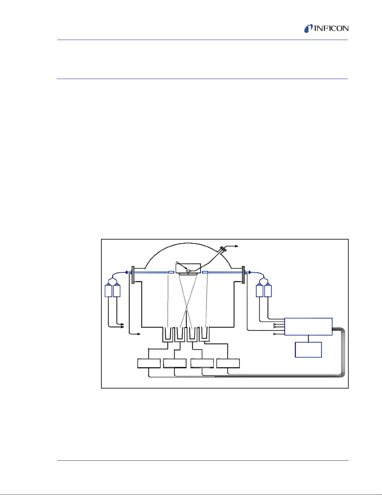
The EIES-IV Guardian uses Electron Impact Emission Spectroscopy (EIES) to
control vacuum deposition of thin films.
In EIES, the material being deposited is energized by a thermionic emitter, which
creates optical emission spectra. An optical filter passes a characteristic
wavelength of the spectra to a detector, which measures the intensity of the
emission. The measured intensity is fed to a PID control loop, which generates a
control signal for the material's evaporation power supply. By proper filter selection,
multiple detectors can control deposition of multiple materials simultaneously.
The EIES-IV Guardian consists of five basic elements: controller, sensor(s),
detector(s), software, and an optional quartz crystal monitor. A four channel, two
sensor system is shown in Figure 1-1. Actual installation must consider source to
sensor alignment requirements, see section 4.2.1, Sensor Position, on page 4-3.
Guardian Co-Deposition Controller Operating Manual
Chapter 1
Introduction and Specifications
Figure 1-1 Four Channel Two Sensor System
IPN 074-517-P1D
1 - 1
Page 16
Guardian Co-Deposition Controller Operating Manual
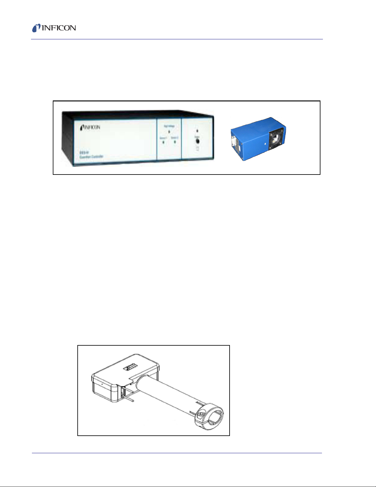
1.2 EIES Controller
The EIES-IV Guardian Controller serves as the interface between the EIES
sensor(s) and detector(s), the evaporation power supply, and the computer running
the EIES software. See Figure 1-2.
Figure 1-2 Guardian Controller with Detector
The controller supplies power to both the filament of the sensor assembly and to
the detector modules. It communicates with each detector, passing the detector
measurements to the computer running the EIES program. Control voltages for
evaporation power supplies are also generated in the controller. Finally, relays and
digital inputs to operate shutters, etc., are included in the controller.
The controller is operated from a computer running the EIES software via RS-232
or Ethernet. Other than a power switch and a few status LEDs, there are no
operator controls on the EIES-IV Guardian Controller.
1.3 EIES Sensor
In the sensor assembly, see Figure 1-4, high-energy electrons from a hot filament
excite the valence electrons of the deposited material. These excited electrons
emit light at wavelengths that are characteristic of each material. A light tube
conducts the light to a feedthrough with a viewport, where it is measured by the
Photomultiplier Tube (PMT) of the detector module(s). A single sensor, see Figure
1-3, can be used to create emissions from multiple materials.
Figure 1-3 EIES Single Sensor 016-400-G1
IPN 074-517-P1D
1 - 2
Page 17
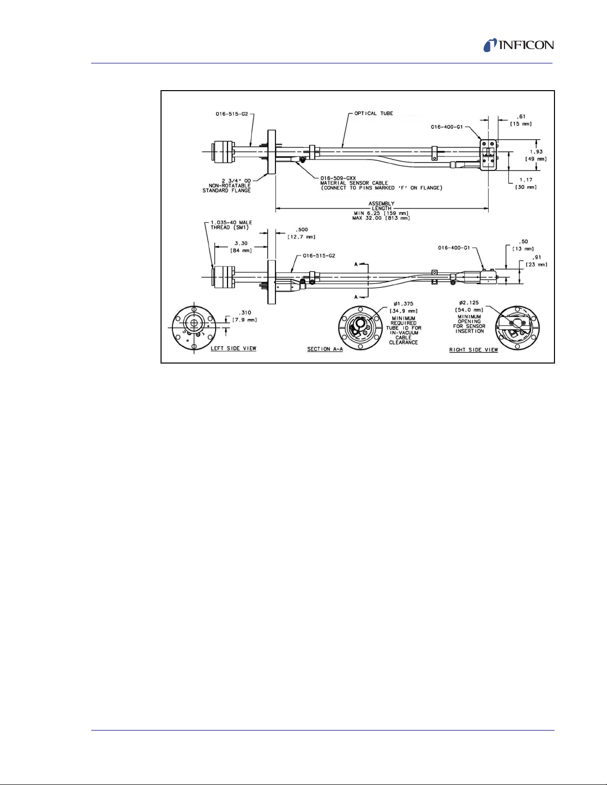
Guardian Co-Deposition Controller Operating Manual
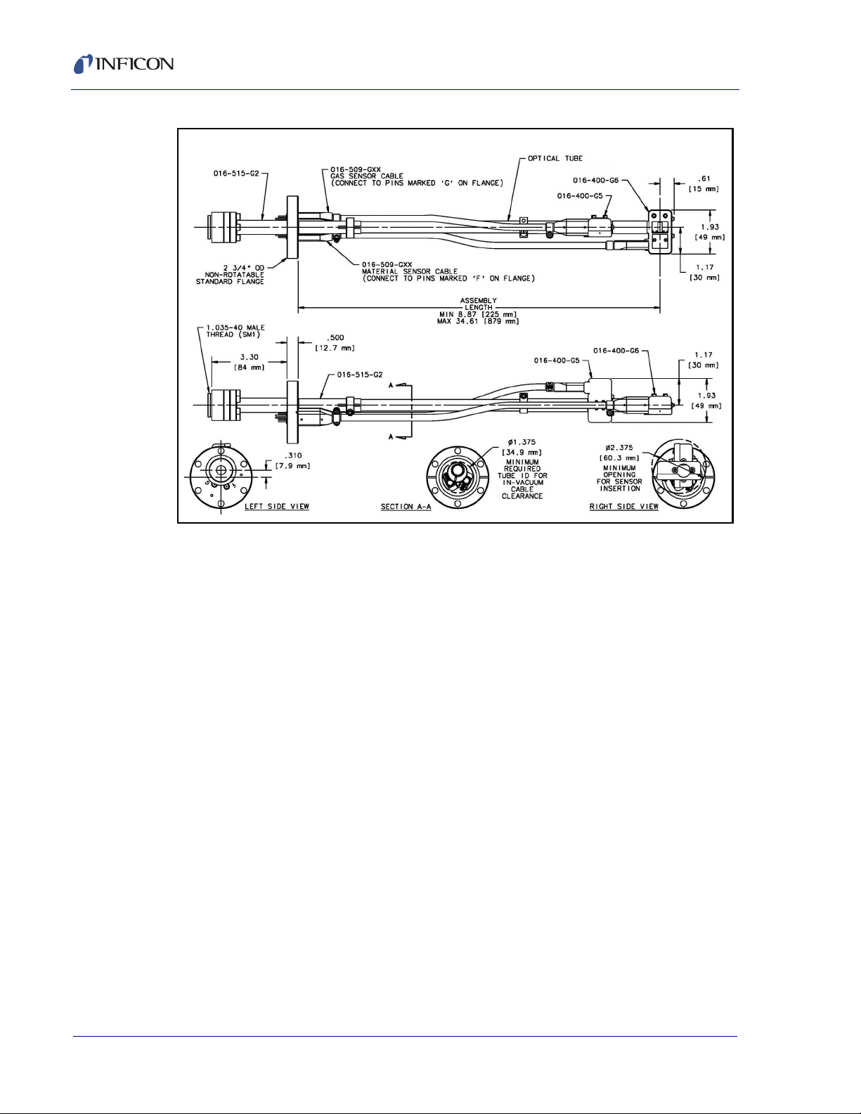
Figure 1-4 EIES Single Sensor and Feedthrough 016-600-Gxx
The sensor assembly consists of a 1.33 in. sapphire viewport attached to a 2.75 in.
Conflat
®
flange. On the vacuum side of the flange, a telescoping light tube and two
electrical connections are attached to the thermionic emitter. The telescoping tube
can be adjusted to locate the thermionic emitter in the vapor flux.
In the Gas Compensating Sensor, Figure 1-5, two sensors are stacked on the same
optical tube with the gas compensating sensor rotated 90 degrees out of the vapor
stream.
NOTE: The sensor will not pass through the 2.75 in.CF (NW35CF) port. If the
chamber is too small to allow installation from the inside, a 4.5 in. CF
(NW63CF) or larger flange adapted to the 2.75 in. CF flange is required to
IPN 074-517-P1D
allow the entire sensor to pass through.
1 - 3
Page 18
Guardian Co-Deposition Controller Operating Manual
Figure 1-5 Gas Compensating Sensor and Feedthrough 016-601-Gxx
1 - 4
IPN 074-517-P1D
Page 19
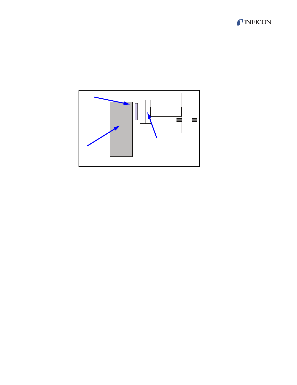
1.4 EIES Detector
Filter
Detector
Sensor
Viewport
The EIES detector module's photomultiplier tube (PMT) measures the emission
intensity of a characteristic wavelength of the deposited material.
For detecting a single material, an optical filter and detector module can be
attached directly to the viewport. See Figure 1-6.
Figure 1-6 EIES Detector
Guardian Co-Deposition Controller Operating Manual
For multiple materials, a fiber optic beam splitter is attached to the viewport. The
split signal is then fed to multiple detectors. Splitting the signal reduces its intensity.
Each detector is fitted with a filter specific to the material it measures.
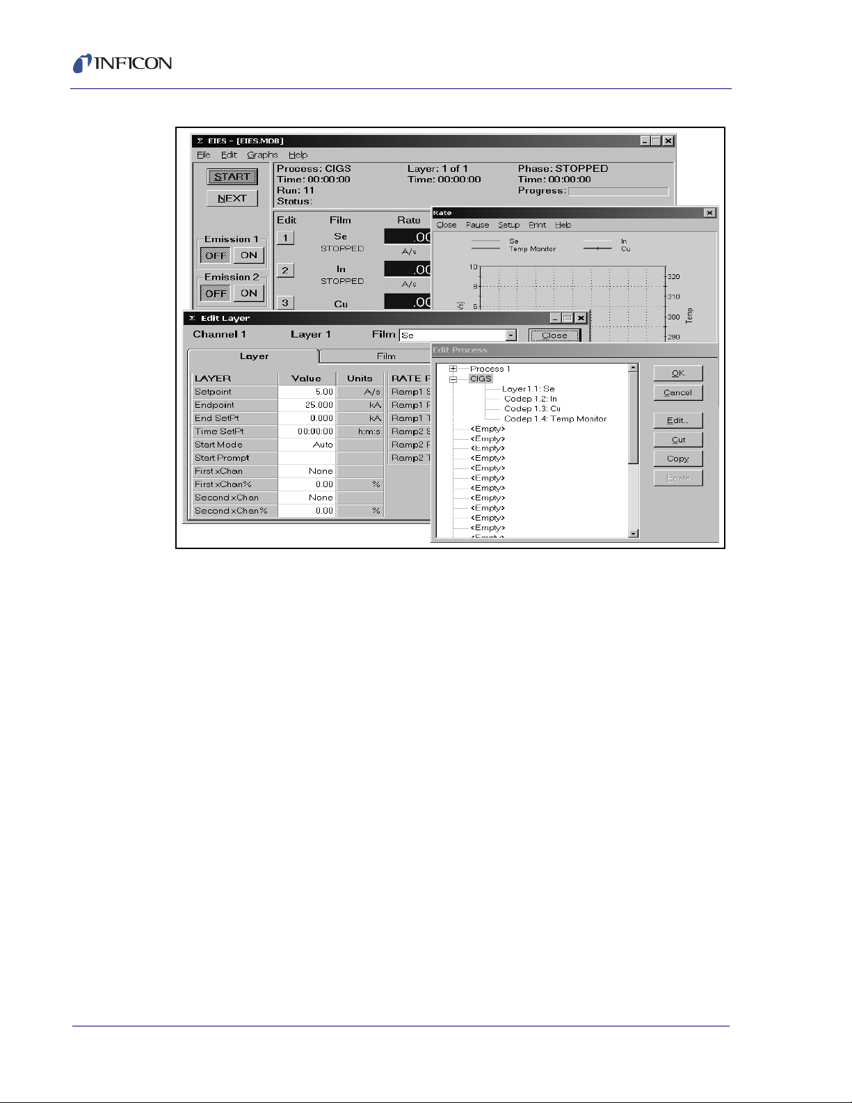
1.5 EIES Software
The EIES software provides the user interface, see Figure 1-7, for operating the
EIES-IV Guardian system. The program provides all of the functions required for
an eight sensor, eight output, multi-layer co-deposition controller. Process settings,
numeric data, and graphs can be displayed during all phases of deposition.
®
The EIES software stores process recipes in a Microsoft
database. Process data is logged to disk in comma-delimited format for easy import
IPN 074-517-P1D
into spreadsheet and graphing programs, such as Microsoft Excel
Chapter 3 details EIES software functions.
Access® compatible
®
.
1 - 5
Page 20
Guardian Co-Deposition Controller Operating Manual
Figure 1-7 EIES Software
1.6 Quartz Crystal Monitor
In the EIES system, rate is proportional to light intensity, measured as detector
current. To calibrate the detector current to actual rate, an optional quartz crystal
monitor (QCM) is available.
The EIES system uses the INFICON SQM-242
for QCM calibration of the EIES detector(s). QCM calibration can be initiated by the
user, or automatically at regular intervals during deposition. Control of a source is
also possible with a QCM input.
A separate Operating Manual covers installation of the SQM-242 or Q-pod, and
hook up of the quartz sensors.
1.7 Analog Measurements
The INFICON SAM-242™ analog input card measures four 0 to +/-10 V (dc)
signals. The SAM-242 card can be used to measure process parameters, such as
temperature and pressure, to control those process variables. The SAM-242 card
is an add-on for the SQM card and is not a stand-alone card.
The SAM-242 card is also installed in the computer running the EIES software.
Installation is covered in the SQM-242 Operating Manual.
™
PCI card or Q-pod™ Transducer
IPN 074-517-P1D
1 - 6
Page 21

1.8 Specifications
1.8.1 Sensor
Type . . . . . . . . . . . . . . . . . . . . . . . . . Single filament hot cathode or Dual filament
Sensor Materials . . . . . . . . . . . . . . . 304 SS, Inconel x-750,Tantalum, Ceramic
Filament Life (typical) . . . . . . . . . . . . ~1000 hours @ 1 x 10
Filament Material . . . . . . . . . . . . . . . Thoria coated Iridium,
Filament Current. . . . . . . . . . . . . . . . 2 to 4 amps
Emission Current . . . . . . . . . . . . . . . Yttria: 2 mA max, Thoria 4 mA max
Bias Voltage . . . . . . . . . . . . . . . . . . . 180 Volts
Operating Pressure . . . . . . . . . . . . . 5 x 10
Operating/Bakeout Temperature
for in-vacuum components . . . . . . . . 450ºC maximum
Guardian Co-Deposition Controller Operating Manual
Gas Compensating
-5
Tor r
Optional Yttria coated
-4
Torr maximum
Size . . . . . . . . . . . . . . . . . . . . . . . . . 1.94 L x 1.03 W x 0.81 H in.
(49 x 26 x 21 mm)
Mounting. . . . . . . . . . . . . . . . . . . . . . 2 ¾ in. CF (NW35CF) with sapphire viewport
Rigid SS tube from 7 in. to 16 in. (175 mm to
405 mm)
Optical Path . . . . . . . . . . . . . . . . . . . 1/2 in. (12.25 mm) dia. 304 SS rigid tube,
centerless ground (
InVac Cable . . . . . . . . . . . . . . . . . . . 16 AWG Mica insulated nickel clad Copper
Cable 016-509-Gxx
Optional ceramic bead insulated 0.050 in.
(1.3 mm) dia. Molybdenum wire Refractory
Cable 016-513-Gxx
IPN 074-517-P1D
External Wiring . . . . . . . . . . . . . . . . . 16 AWG except 18 AWG ground conductor,
40' (12 m) maximum
1 - 7
Page 22

Guardian Co-Deposition Controller Operating Manual
1.8.2 Detector
Photomultiplier Tube (PMT) . . . . . . . Hamamatsu R7518 or equivalent
Spectral Response. . . . . . . . . . . . . . 185 to 730 nm
Detection Limit . . . . . . . . . . . . . . . . . >5 fW of optical input power
PMT Gain . . . . . . . . . . . . . . . . . . . . . 10
Resolution . . . . . . . . . . . . . . . . . . . . 20 bits
Mounting . . . . . . . . . . . . . . . . . . . . . 1.035 in. x 40 threads per Compatible with
Filter Holder . . . . . . . . . . . . . . . . . . . 1 in. (25 mm) diameter x .2 in. (5 mm) thick
Size . . . . . . . . . . . . . . . . . . . . . . . . . 2 x 5½ x 2¾ in. (50 x 140 x 70 mm)
Weight . . . . . . . . . . . . . . . . . . . . . . . 1.7 lb. (0.8 kg)
Wiring . . . . . . . . . . . . . . . . . . . . . . . . DB9 Male/Female, 40 ft. (12 m) maximum
Warm Up . . . . . . . . . . . . . . . . . . . . . Allow the detector to warm up for one hour
3
to 107, programmable
Omega SM1 series
filters
for maximum stability.
1.8.3 Controller
Sensors . . . . . . . . . . . . . . . . . . . . . . 1, 2 optional
Detectors . . . . . . . . . . . . . . . . . . . . . 8
Source Control Outputs . . . . . . . . . . 8 outputs, 0 to ±10 V (dc) programmable
Digital I/O . . . . . . . . . . . . . . . . . . . . . 12 relays 30 V (dc), 3 A,
Communications . . . . . . . . . . . . . . . RS-232 or Ethernet static IP address
Power . . . . . . . . . . . . . . . . . . . . . . . . 100-240 V~ ±10% nominal, 50/60 Hz, 110 W
Fuse . . . . . . . . . . . . . . . . . . . . . . . . . 250 V 1.6 A T
Size . . . . . . . . . . . . . . . . . . . . . . . . . 19 x 3 ½ x 12 in. (483 x 89 x 305 mm)
Weight . . . . . . . . . . . . . . . . . . . . . . . 8.5 lb. (3.9 kg)
Computer . . . . . . . . . . . . . . . . . . . . . Windows 2000/XP/Vista/7, user supplied
12 inputs 5-12 V (dc)
IPN 074-517-P1D
1 - 8
Page 23

Guardian Co-Deposition Controller Operating Manual
Operating Environment . . . . . . . . . . 0°C to 40°C
0 to 80% RH non-condensing
0 to 2,000 meters
Indoor Use Only
Class 1 Equipment (Grounded Type)
Suitable for Continuous Operation
Ordinary Protection (not protected against
harmful ingress of moisture)
Pollution Degree 2
Installation (Overvoltage) Category II for
transient overvoltages
Storage Environment . . . . . . . . . . . . -40°C to 40°C
IPN 074-517-P1D
1 - 9
Page 24

Guardian Co-Deposition Controller Operating Manual
This page is intentionally blank.
1 - 10
IPN 074-517-P1D
Page 25
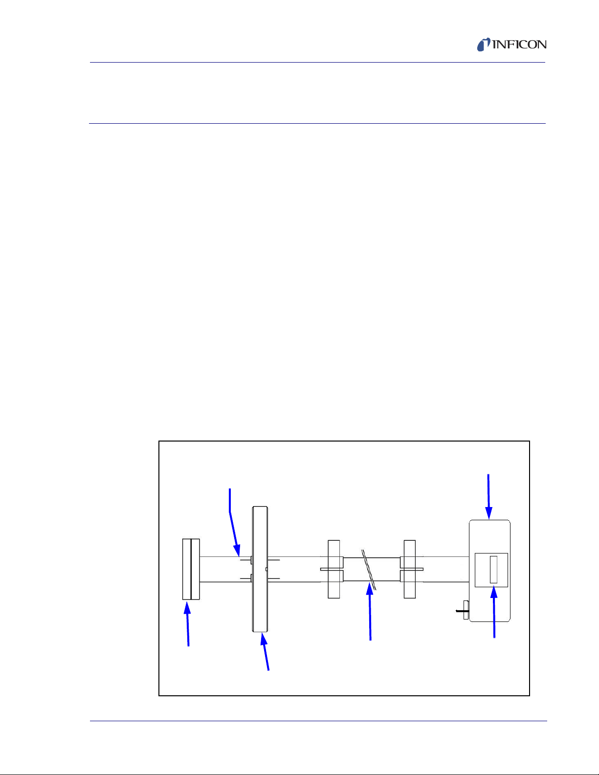
2.1 Introduction
Electrical Feedthroughs
For Sensor Filament
Sapphire Window
1.33 in. CF Flange
2.75 in. CF Flange
Telescoping Tubing
For Length Adjustment
Vapor
Flux
EIES Sensor
This section covers the minimum system connections and software setup needed
to run the EIES-IV Guardian system. Consult later chapters for more detailed
installation and operating instructions.
2.2 Installation
2.2.1 Sensor Installation
Placement of the EIES sensor is the most significant factor determining EIES
system performance. The sensor must be placed so that the material vapor flux
reaches the sensor without obstruction. The sensor opening must be oriented so
that material can pass through the sensor without accumulating inside the sensor,
with the smaller sensor cutout toward the flux. See Figure 2-1. See Chapter 4 for
detailed installation instructions.
Guardian Co-Deposition Controller Operating Manual
Chapter 2
Quick Start
IPN 074-517-P1D
NOTE: The sensor will not pass through the 2.75 in.CF (NW35CF) port. If the
chamber is too small to allow installation from the inside, a 4.5 in. CF
(NW63CF) or larger flange adapted to the 2.75 in. CF flange is required to
allow the entire sensor to pass through.
Figure 2-1 Sensor Placement
2 - 1
Page 26
Guardian Co-Deposition Controller Operating Manual
016-205-P2
Standard Rate Cover
016-205-P1
High Rate Cover
To install the sensor, loosen the collar that secures the telescoping tube and
separate the 2.75” flange from the sensor assembly. Install the 2.75 in. CF
feedthrough to the vacuum chamber port, with the telescoping tube inside the
chamber.
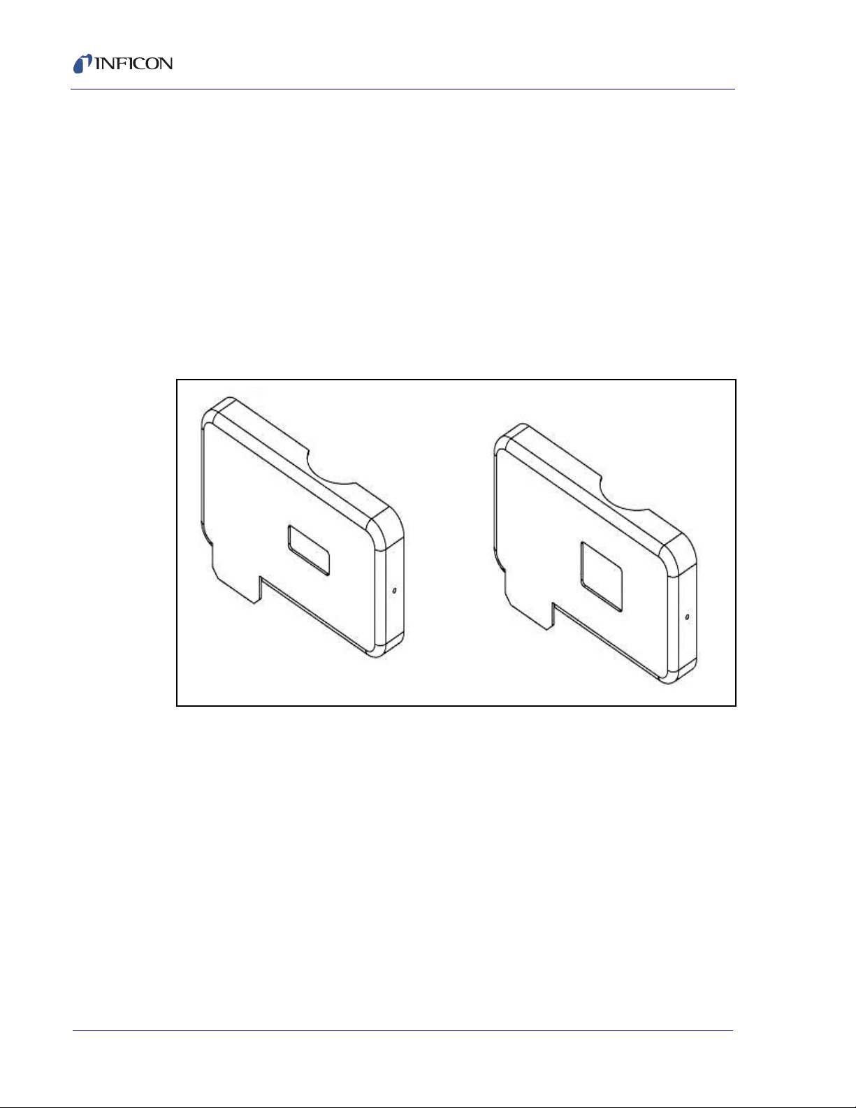
2.2.1.1 Sensor Covers, High Rate and Standard Rate
The High Rate cover 016-205-P1 is shipped installed on the flux sensor. The
Standard Rate cover 016-205-P2 is shipped separately in a poly bag. For MBE and
other applications where the sensor receives deposition rates below 10 Å/s or the
emission signal is weak, the Standard Rate cover may be preferable as it allows
more evaporant to enter the sensor. When replacing covers, be sure the cover is
securely snapped in place.
Figure 2-2 High Rate and Standard Rate Covers
2 - 2
In the vacuum chamber, slide the sensor assembly onto the telescoping light tube
and adjust the length so that the vapor flux passes through the sensor. The smaller
opening in the sensor cover points toward the evaporant. If necessary, provide
mechanical support to stabilize the sensor assembly. However, do not block the
flux path. Secure the assembly by tightening the tube collar.
Attach the cables from the feedthrough to the sensor. For a standard sensor, attach
the in-vacuum cable to the pins marked "F" (Flux). For a gas compensating sensor,
attach the cable from the outermost sensor to the pins marked "F". Attach the
in-vacuum cable from the inner sensor to the pins marked "G" (Gas). Assure there
are no potential shorting paths to the chamber. The outermost sensor’s cover must
be aligned to allow evaporant material to pass through it, entering at the smaller
rectangular opening and exiting at the large opening. The gas sensor will be
oriented at a right angle relative to the flux sensor and its cover will have several
small holes to permit residual gas to enter, but no evaporant material.
IPN 074-517-P1D
Page 27
Guardian Co-Deposition Controller Operating Manual
CAUTION
2.2.2 Detector—Direct Installation
For single detector applications, the detector may be mounted directly to the
sensor assembly viewport. Please see section 4.3.2, Single-Detector Systems, on
page 4-8 for detailed installation instructions.
2.2.3 Sensor to Fiber Optic Installation
In multi-material applications, a fiber optic beam splitter attached to the viewport
can tailor signal transmission and detector mounting to your needs. Contact
INFICON for fiber optic beam splitting requirements and capabilities. Please see
section 4.3.3, Multiple-Detector Systems, on page 4-8 for detailed installation
instructions.
Be sure power to the PMT Detector Module is turned off
whenever the PMT is exposed to room light to avoid
damage to the PMT.
IPN 074-517-P1D
2 - 3
Page 28
Guardian Co-Deposition Controller Operating Manual
CAUTION
CAUTION
WARNING
WARNING
2.2.4 Controller Installation
Mount the controller in a location that allows easy wiring access to the EIES sensor
and detector assemblies. The controller may be placed up to 25 ft. from the EIES
computer. See section 4.6, Controller Installation, on page 4-17
Properly ground the system. Connect a heavy braided
cable from the EIES controller to vacuum chamber
ground. If you are using multiple power supplies, be sure
that the outer conductor of each BNC cable is at system
ground potential.
Digital Inputs and Relays: Consult Chapter 4 for information on digital I/O wiring.
A system interlock must be present. Plug the Interlock
connector 782-505-077 (jumpers pin 1 to 10 and pin 3 to
16) supplied in the 782-703-G1 Ship Kit into the Inputs
connector. Emission cannot be turned on unless this
connector or an equivalent system interlock is present.
Power: With the power switch OFF, connect the AC mains to the controller power
input. The controller automatically accepts 100-240 V (ac), 50-60 Hz.
NOTE: Observe the power-up sequence described below to avoid power glitches
appearing at the evaporation power supply outputs during startup.
Power up in this sequence: Press the power switch on
the Guardian controller. Next, start the EIES Software.
Last, turn on the evaporation power supplies.
Verify that the power cable provided is connected to a
properly grounded mains receptacle.
IPN 074-517-P1D
2 - 4
Page 29
WARNING
Maintain adequate insulation and physical separation of
WARNING
sensor, detector, and I/O wiring from hazardous voltages.
Relay contacts are rated for 30 V (dc) maximum duty. Any
customer supplied relay contact circuit must be fused at
not more than 5A if the circuit is capable of supplying
more than 5A, including the available short circuit
current.
2.2.5 QCM Option Installation
If an SQM-242 or Q-pod will be used for calibration or control, follow its Operating
Manual to install the QCM software and sensor(s).
For accurate rate calibration, locate the QCM sensor(s) in the vacuum chamber so
that the QCM sensor(s) receives a representative sample of the materials being
deposited.
Guardian Co-Deposition Controller Operating Manual
2.3 EIES Software
Leave the Guardian Controller power OFF while you become familiar with the EIES
program. This section will introduce the concepts necessary to operate the EIES-IV
Guardian system.
2.3.1 Software Installation
Insert the INFICON Program Disk into your CD-ROM drive. The Products Menu
should appear after a few seconds, see Figure 3-2 on page 3-3. If not, open
IPN 074-517-P1D
Windows Explorer and run the UtilityDisk.exe program on the CDROM.
On the Products Menu, click EIES-IV Guardian. When EIES software installation
finishes, you may be prompted to restart your computer.
2 - 5
Page 30
Guardian Co-Deposition Controller Operating Manual
Control
Panel
Readings
Panel
Status
Panel
2.3.2 EIES Main Screen
Click the EIES-IV icon on your desktop (or click Start >> Programs >> INFICON
>> EIES-IV). Initially, your display may look slightly different than Figure 2-3.
Figure 2-3 Process Display
The EIES main screen shows operating controls for running your process in the left
Control Panel. Process status information is in the top Status Panel. Below the
Status Panel is the large Readings Panel where individual channel readings are
displayed.
The readings panel has three display modes: Process, Ratio and Readings. Click
View >> Process to see the Process display. The Process display shows process
related information such as films, setpoints, and manual operating controls.
The Ratio display is similar to the Process display except that the deviation
readings are replaced with the ratio of the channel’s reading to another channel.
The other channel number is shown below the ratio reading. Ratios are set up in
the Edit Layer dialog box. See Ratio Display Grid on page 3-20, for more
information on channel ratios.
Click View >> Readings to see the Readings display, Figure 2-4. This display
shows unfiltered readings from all sensors and detectors. The Readings display is
useful for equipment setup and troubleshooting.
IPN 074-517-P1D
2 - 6
Page 31

Figure 2-4 Readings Display
Guardian Co-Deposition Controller Operating Manual
Notice that, unlike the previous display, there are several references to a Gas
sensor in both the Readings Panel and the Control Panel. The EIES Guardian
controller can be configured for standard EIES sensors or Gas Compensating (GC)
sensors. When a Gas Compensating controller is detected, the extra controls and
readings are displayed automatically. Operation with GC sensors is covered later
in the manual.
IPN 074-517-P1D
2 - 7
Page 32

Guardian Co-Deposition Controller Operating Manual
2.3.3 Edit Film
Each material deposited will require unique setup parameters for proper
deposition. 25 materials can be programmed. Click the Edit >> Films to display the
Edit Film dialog box shown in Figure 2-5.
Figure 2-5 Edit Film Dialog Box
Click the film drop-down to see a list of all films. Select the first film in the list, then
click the Rename button. Change the film name to Cu, for Copper. This film will
define the basic deposition parameters for Copper. We could adjust the film
parameters, but for now we'll just rename a few more films.
Use the film drop-down to Rename the next three films In, Ga and Se. Close the
Edit Film dialog box and return to the main screen.
2.3.4 Edit Processes
Select Edit >> Processes to view a listing of the 25 processes. A process is a
sequence of layers, each consisting of one or more deposited films. We will use the
Edit Process dialog box to create a multi-layer co-deposition process.
Click the first process, then click Edit. Name the first process CIGS. We will
construct an arbitrary layer sequence using arbitrary parameters for each.
Processes are shown in an outline view, similar to Windows Explorer. Click the +
beside a process to expand the process and show the individual layers. Click - to
collapse the view of the process.
IPN 074-517-P1D
2 - 8
Page 33

Guardian Co-Deposition Controller Operating Manual
Layers are numbered sequentially starting at layer 1. After the layer number is the
EIES software channel that will display readings. Next is the EIES Guardian output
that will control the deposition power supply. And finally, the film that will be
deposited.
It is important to know which channels and outputs are being used in co-deposition,
to avoid assigning more than one film to the same measurement channel or control
output.
Now, click the first layer of process CIGS (don't worry if the material is different than
shown below). Be sure the first layer is highlighted, then click the Copy button; see
Figure 2-6.
Figure 2-6 Selecting First Layer of Process CIGS
This places a copy of the selected layer on the edit clipboard and enables the Paste
button. With the first layer still highlighted, click the CoDep option below the Paste
button, and then click the Paste button. See Figure 2-7.
IPN 074-517-P1D
2 - 9
Page 34

Guardian Co-Deposition Controller Operating Manual
Figure 2-7 CoDep Option
A co-deposition film has been added to the first layer. Click Paste again to create
a three film co-deposition layer.
Now select the Below option and click Paste to add a second layer below layer 1.
Finally, select the CoDep option and click Paste to add a CoDep film to layer 2.
See Figure 2-8.
Figure 2-8 Pasting CoDep Layer
IPN 074-517-P1D
2 - 10
The CIGS process now consists of Layer1 and Layer2. Layer1 will co-deposit three
films, and Layer2 will co-deposit two films. However, the channel, output, and films
are all duplicates. We will correct that error in the next section.
Page 35

2.3.5 Edit Layer
Highlight Layer 1: Ch:1 Out:1 Cu and click Edit to display the Edit Layer dialog
box. See Figure 2-9.
The Edit Layer dialog box shows all of the parameters needed to deposit the
selected layer. At the top of the dialog box you select the measurement channel
and output to be used, and the film to be deposited in this layer. Select Channel 1,
Output 1, and Film Se. We will set this up to be a QCM channel.
Figure 2-9 Edit Layer Dialog Box
Guardian Co-Deposition Controller Operating Manual
Select the Layer tab and set the rate Setpoint to 10 Å/s, and the thickness Endpoint
to 100 kÅ.
IPN 074-517-P1D
2 - 11
Page 36

Guardian Co-Deposition Controller Operating Manual
Click the X Chan tab to view the settings used to eliminate cross channel
interference and display the ratio of two channel’s reading. For now we will not use
these features. See Figure 2-10.
Figure 2-10 Settings Used To Eliminate Cross Channel Interference
2 - 12
IPN 074-517-P1D
Page 37

Guardian Co-Deposition Controller Operating Manual
The Film and Film Cal(ibration) tabs are for the selected film, Se. On the Film tab
set preconditioning Ramp1 Power, Ramp1 Time, and Soak1 Time as shown in
Figure 2-11.
Figure 2-11 Film Tab Settings
IPN 074-517-P1D
2 - 13
Page 38

Guardian Co-Deposition Controller Operating Manual
Now select the Film Cal(ibration) tab and verify Channel Input and Cal. QCM# are
as shown in Figure 2-12. Note that the software for the Q-pod or SQM242 QCM to
be used must be installed per the relevant instructions. Tooling must be established
as described in the QCM manual or in this manual under Tooling Factor on page
6-7.
Channel numbers correspond to inputs from up to eight EIES Detector Modules,
up to four QCM inputs or up to four SAM inputs. Any combination using up to eight
inputs for rate control is possible.
Figure 2-12 QCM Film Calibration Tab
2 - 14
Keep in mind that parameters on the Layer and X Chan tabs are unique to this
layer. Those on the Film and Film Calibrate tabs pertain to any layer using the film.
Take a few minutes to review the parameters on each tab. As you hold your mouse
pointer over each parameter, a brief explanation appears. You can also press F1
to view the help file for the selected tab.
IPN 074-517-P1D
Page 39

Guardian Co-Deposition Controller Operating Manual
When you are ready, return to the Edit Process dialog box shown in Figure 2-13
and click the indented CoDep film, immediately below Layer 1 Ch:1 Out:1 Se.
The Edit Layer dialog box will update to show the parameters for the selected layer.
In the Edit Layer dialog box, set this CoDep film to Channel 2, Output 2, and select
film In. On the Layer tab, enter a Setpoint of 5 Å/s and an Endpoint of 5 kÅ. On the
Film tab, set Ramp1 Power to 25% and set the remaining Film parameters to match
those for Se, as shown on the previous page. In the Film Cal tab, select EIES as
Input and set Cal QCM# to 2,
Figure 2-13 Edit Process
Return to the Edit Process dialog box and click the CoDep film immediately below
Codep Ch:2 Out 2 In. In the Edit Layer dialog box, set this CoDep film to Channel
3, Output 3, and film Ga. On the Layer tab, enter a Setpoint of 2 Å/s and an
Endpoint of 2 kÅ. On the Film tab, set Ramp1 Power to 15%. Edit the remaining
Film and Calibrate parameters to match those for In, as shown on the previous
IPN 074-517-P1D
page. That completes the definition of the first co-deposition layer, consisting of Se,
In, and Ga.
Edit Layer 2 so that the first entry is Layer 2 Ch:1 Out:1 Se with a rate Setpoint of
10 Å/s and thickness Endpoint of 10 kÅ. Change the codep layer for Layer 2 to
CoDep Ch:4 Out: 4 Cu with a Setpoint of 3 Å/s and Endpoint of 3 kÅ EIES Input.
When you are finished, you should have a 2-layer CIGS process as shown in
Figure 2-14.
2 - 15
Page 40

Guardian Co-Deposition Controller Operating Manual
Figure 2-14 2-Layer CIGS Process
Click OK to return to the main screen with CIGS as the active process.
2.3.6 Views
On the main screen, click the View menu and select 3. Power. You may want to
rearrange some program windows at this point. You can also resize the graph by
dragging its window border.
Figure 2-15 Power Graph
IPN 074-517-P1D
2 - 16
Graph 3.Power is normally a graph of the output power of the active channels
during deposition.
Page 41

Guardian Co-Deposition Controller Operating Manual
Click Setup on the graph menu to show the Graph Setup dialog box.
Figure 2-16 Graph Setup Dialog Box
Assign channels 1 to 4 by checking the Show Channel check boxes. Also, check
Graph On Top to keep the graph above other windows. When your Graph Setup
dialog box matches the one above, close the Graph Setup dialog box.
2.3.7 Software Summary
Spend some time with this process to become familiar with its setup. Especially, the
creation of a multi-layer and codeposition layer process. Also, review the
parameters contained in the Layer Edit screen. The Layer Edit screen will be
crucial to fine tuning your process.
IPN 074-517-P1D
2 - 17
Page 42

Guardian Co-Deposition Controller Operating Manual
2.4 Initial Setup
Connect the Guardian controller rear panel RS-232 connector to your computer
serial port using a straight through DB-9 Male-Female cable (IPN# 068-0464 in
Guardian ship kit). Connect your detector module(s) to the rear panel of the
Guardian controller with 782-505-065 (3 m) or 782-505-065-40 (10 m) cable(s).
2.4.1 Power-up Sequence
1 Press the power switch on the Guardian controller.
2 Start the EIES Software.
3 Turn on the evaporation power supplies.
2.4.2 Communications
If a Comm Error message appears on the main screen status line, click Edit >>
System, and the Comm tab. Select the Comm Port used for communications with
the Guardian controller.
Figure 2-17 Selecting Comm Port
If you are connecting to the Guardian controller by Ethernet, select Ethernet in the
Comm Port drop-down. Enter the Port (typically 2101) and address (default factory
setting is 192.168.1.200) .
IPN 074-517-P1D
2 - 18
When the proper communications parameters are entered and communication is
successfully established, the main screen Comm Error message will disappear and
the screen will show Version x.xx where x.xx is the firmware version in the
controller.
Page 43

2.4.3 Detector Calibration
The internal electronics of each EIES detector module are pre-calibrated at the
factory. To compensate for background noise once installed to a system, the
following calibration must be performed.
NOTE: Allow 1 hr warm-up for the PMT to reach optimum stability. If you replace
or exchange a detector, you must recalibrate!
To calibrate a detector, select the Channel tab of the System Edit dialog box.
Select the Channel you want to calibrate. Sensor emission should be off.
Figure 2-18 System Edit Channel Tab
Guardian Co-Deposition Controller Operating Manual
Verify that a “No Response!” error message is not shown below the Start button in
the calibration frame. If it is, check the detector to controller cable. You can also try
powering the controller off, then on. Establishing ethernet connection may take a
IPN 074-517-P1D
minute or more.
Set the detector Update rate to 10 Hz and Cal Readings to 10.
When there are no errors, click the Start calibrate button. The screen will indicate
the calibration process and end with a Calibration Complete message.
Select and calibrate any additional detector channels.
2 - 19
Page 44

Guardian Co-Deposition Controller Operating Manual
CAUTION
2.4.4 Sensor Setup
The Guardian controller can operate up to two standard or gas compensating
sensors. During operation, the controller must maintain a constant sensor emission
current. As a sensor is used and material is deposited on the sensor, an unwanted
leakage current can develop. When the leakage current becomes too large, the
Guardian controller can no longer control emission current.
The Emission current can be set as high as 10 mA but must be set at no more
than 4 mA when using 016-Series Thoria filaments and 2 mA when using
016-Series Yttria filaments. Correct emission current is stated on a label attached
to the plastic bag the sensor or replacement emitter was packaged in. Leakage
setting of 1/2 the emission current setting is recommended for most applications.
See Chapter 3 for more information on sensor setup.
Refer to the label attached to your sensor or emitter
assembly package for correct emission current settings.
Do not operate 016-xxx series sensors with Yttria
filaments at Emission current greater than 2 mA. Instant
filament failure may occur! 016-xxx series sensors with
Thoria filaments may be operated at 4 mA emission.
Figure 2-19 Edit System Sensor Tab
IPN 074-517-P1D
2 - 20
Page 45

Guardian Co-Deposition Controller Operating Manual
Guardian controllers with Gas Compensating sensors have additional Emission
and Leakage parameters for the gas sensor. A Gas Calibration factor is used to null
the gas effect from the main sensor readings. See Figure 2-20.
Figure 2-20 Gas Calibration Factor
See Sensor Tab on page 3-30 for a description of the Gas Cal parameter. For now,
uncheck Enable Gas Sensors if it is checked.
2.4.5 QCM Option
If you installed the optional SQM-242 card or Q-pod, click the QCM tab of the Edit
System dialog box.
Figure 2-21 QCM Tab
IPN 074-517-P1D
2 - 21
Page 46

Guardian Co-Deposition Controller Operating Manual
If the SQM-242 card is installed properly, Card: 2.XX, DLL: OK is displayed. If you
are using a Q-pod, its serial number appears. Verify that each sensor attached to
the QCM displays a frequency reading on the main screen.
2.4.6 Digital I/O
The I/O tab of the Edit System dialog box assigns the Guardian controller's relays
and digital inputs to program functions. See Figure 2-22. Most digital I/O is not
necessary for initial operation. Consult Chapter 3 for I/O programming, Chapter 4
for I/O wiring.
Figure 2-22 I/O Tab
2.5 Operation
This section assumes that you have worked through the example process of
section 2.2 on page 2-1 and the initial detector calibration of section 2.3 on page
2-5.
2.5.1 Build a Single Layer Process
Build a simple single-layer, single-film process in the EIES program and make it the
active process (refer to section 2.2 on page 2-1). Verify that the EIES channel you
are using has no errors, and shows a reading near zero (refer to section 2.3 on
page 2-5).
2 - 22
IPN 074-517-P1D
Page 47

2.5.2 Setup Layer Parameters
Display the Edit Layer dialog box for the channel you are using by clicking the Edit
button to the left of that channel on the main screen. Select the Layer tab of the
Edit Layer dialog box, see Figure 2-23, and verify that the Endpoint is a value high
enough to avoid prematurely halting the process during calibration.
Figure 2-23 Endpoint Value
Guardian Co-Deposition Controller Operating Manual
On the Film tab, verify that the Full Scale voltage matches the input of your power
supply. Also verify that Max. Power is consistent with the material you are
evaporating.
IPN 074-517-P1D
2 - 23
Page 48

Guardian Co-Deposition Controller Operating Manual
Figure 2-24 Film Tab Full Scale Voltage
Select the Film Cal(ibration) tab, and verify that the PMT volts setting is about 700.
Figure 2-25 PMT Voltage Setting
IPN 074-517-P1D
2 - 24
If you are using QCM calibration of the EIES measurements, select the proper
QCM Sensor# and enter the material Density and ZFactor (Z-Ratio) (see Appendix
B). For now, it is probably best to disable QCM calibration by setting Cal QCM# to
None.
Page 49

2.5.3 Start Deposition
NOTE: Pump down the vacuum chamber to below 1E-5 Torr before operating the
EIES-IV system! Allow 1 hr warm-up for the PMT to reach optimum
stability.
On the EIES main screen verify that there is no error message in the Film column
on the channel(s) being used, and verify that Rate reading is near zero.
Figure 2-26 Verifying Rate Reading is Near Zero
Guardian Co-Deposition Controller Operating Manual
On the main screen, turn Emission ON for the EIES sensor(s) you are using by
clicking ON under the sensor number on the left side of the screen. The rate
reading on each channel should still be near zero, but changing slightly.
Turn on your evaporation power supply. Click the Channel 1 Manual Power button
(on the right side of the screen). Enter a small power value and press Enter to send
the value to the power supply. Slowly increase power until the material vaporizes
IPN 074-517-P1D
and the rate reading starts to increase above zero.
If everything looks OK, increase the power to near the desired deposition rate. The
deposition rate can be determined before EIES calibration from previous
experience with the power supply output level, another measurement reference, or
from the optional QCM readings.
To optimize the detector PMT voltage, select View >> Readings to show the
detector readings. Click the channel Edit button. See Figure 2-27.
2 - 25
Page 50

Guardian Co-Deposition Controller Operating Manual
Figure 2-27 Channel Edit Button
The Edit Layer dialog box is displayed. On the Film Cal. tab of the Edit Layer dialog
box, adjust the PMT Volts until the readings for the appropriate channel are stable
and low.
HINT: Low PMT values cause low flux readings. High values increase noise and
may saturate the PMT.
Figure 2-28 Film Calibration Tab PMT Voltage
IPN 074-517-P1D
2 - 26
Page 51

2.5.4 Manual Calibration
Cal. Gain
EIES Measure Rate
Actual Rate
-----------------------------------------------=
Calibrate the main screen rate reading to match the actual rate by entering a Cal.
Gain on the Edit Layer, Film Cal. tab. The Cal. Gain parameter is calculated by
equation [1].
2.5.5 QCM Calibration
If you are not using the QCM calibration option, skip to section 2.5.6.
If you are using the QCM calibration option, select View >> Readings to display
the QCM readings grid. Verify that the QCM measured rate is as expected. The
QCM measured rate will be used to calibrate the EIES detector channel.
On the Edit Layer dialog box, Film Cal. tab, click calibrate Start. After a few
seconds the calculated Cal. Gain will appear. Verify that the main screen's rate
reading matches the QCM rate.
Guardian Co-Deposition Controller Operating Manual
[1]
2.5.6 Stop Deposition
This completes the initial operational checkout. Set Manual Power to zero on the
main screen to stop deposition. If you previously pressed Start, click Stop to halt
the process.
IPN 074-517-P1D
2 - 27
Page 52

Guardian Co-Deposition Controller Operating Manual
This page is intentionally blank.
2 - 28
IPN 074-517-P1D
Page 53

3.1 Introduction
The EIES-IV Guardian Windows program is a turnkey deposition control program
for the EIES Guardian controller. The program uses ASCII commands to
communicate with the Guardian controller. The EIES-IV Guardian software is a
powerful PC-based thin film deposition controller that can:
Measure up to eight materials simultaneously.
Operate two standard or gas compensating (GC) sensors.
Control up to eight deposition sources simultaneously.
Calibrate EIES sensors against quartz crystal sensors (SQM-242 or Q-pod
option).
Guardian Co-Deposition Controller Operating Manual
Chapter 3
EIES Software
Control analog variables such as temperature and pressure (SAM-242 option).
Store up to 25 processes and 250 layers on disk.
Graph, and log deposition data to disk, for process documentation and
analysis.
The current version 4.11 EIES-IV Guardian software is compatible only with version
4.x firmware and vice versa. Version 5.11 software only allows 2 mA operation and
is otherwise identical to version 4.11. Firmware versions prior to 4.x are compatible
with version 2.x EIES-IV Guardian software. The controller firmware is shown on
the instrument label affixed to the controller side panel. Earlier versions of the
controller may not have this label.
NOTE: If parameters are sent to the Guardian via external communications using
commands as described at section 7.3, Guardian Controller Direct
IPN 074-517-P1D
NOTE: New parameters sent to the Guardian via the ActiveX interface described
A typical deposition cycle for a thin film can be broken into three distinct phases:
pre-conditioning (ramp/soak), deposition, and post-conditioning (idle).
Communications, on page 7-8, the new parameters will not be updated on
the EIES-IV Guardian software screens.
at section 7.2, ActiveX (COM) Interface, on page 7-1, will be shown after
the relevant screen is closed and reopened.
3 - 1
Page 54

Guardian Co-Deposition Controller Operating Manual
Figure 3-1 3 Phases of Deposition Cycle
During pre-conditioning, the source material is prepared for deposition. The first
ramp/soak pre-conditioning phase is used to bring the material to a uniform molten
state. The second ramp/soak phase is typically set to a power that produces
evaporation below but near the desired deposition rate.
When pre-conditioning ends, PID rate control of deposition begins. Initially, the
substrate material may remain shuttered until the desired deposition rate is
achieved (shutter delay). Once the control loop achieves the desired rate, the
shutter opens and deposition begins. During deposition, multiple rates (rate ramps)
can be programmed.
When the desired thickness is reached, the evaporation source can be set to zero
or non-zero idle power. At this point the process may be complete, or deposition of
another layer may begin. Up to eight separate films can be co-deposited within a
single layer.
In addition to using EIES PMT detector modules for rate control, QCM inputs (from
INFICON's SQM-242 card or Q-pod) can also be used to control deposition, or to
calibrate the EIES PMT detector module. DC voltage inputs (measured by
INFICON's SAM-242 card) can also be used to control other process variables.
IPN 074-517-P1D
3 - 2
Page 55

3.2 Installation
NOTE: The EIES program may be installed and used in Simulate mode without an
To install the EIES software, insert the INFICON Program CD-ROM. If the setup
program does not start automatically, click Start, then Run, then type
<d>:UtilityDisk (where <d> is the drive you are using). The Program Disk main
menu should appear.
On the program disk menu, see Figure 3-2, click EIES Guardian Deposition
Controller, then click on EIES Guardian Software and follow the directions given
there. When installation is complete, you may be prompted to restart the computer.
Figure 3-2 Program Disk Menu
Guardian Co-Deposition Controller Operating Manual
EIES-IV Guardian controller. This is useful for learning the software, and
for off-line process development.
To start the EIES program, click the EIES desktop icon, or click Start, Programs,
IPN 074-517-P1D
INFICON, then EIES. The EIES program main screen will be displayed.
NOTE: The following description covers operation without a Guardian connected.
If a Guardian is to be connected at this time, select the communications
interface as described at section 3.8.5, Comm Tab, on page 3-35 before
proceeding. To make RS232 connections, connect a serial cable from the
Guardian serial port to the computer’s serial port. The cable required is a
DB9 female-to-male. Guardian baud rate is fixed at 115,200 and the
communications format is No Parity, 8 bits, 1 stop bit. To make ethernet
connections, connect an ethernet cable and set the IP Address as
described at section 3.8.5, Comm Tab, on page 3-35.
3 - 3
Page 56

Guardian Co-Deposition Controller Operating Manual
Figure 3-3 EIES Program Main Screen
The EIES main screen displays the last used Process, and the film(s) defined for
the first layer of the process. In Figure 3-3, three films (Se, In, and Cu) will be
deposited simultaneously in the first layer.
The main screen can show from four to eight channels of data. For most users four
channels will be adequate. To select the number of channels displayed, click the
Edit menu, then System. On the System Edit dialog box, see Figure 3-4, select
the Display tab. Select the number of channels you want to Show.
Figure 3-4 Edit System Display Tab
IPN 074-517-P1D
3 - 4
Page 57

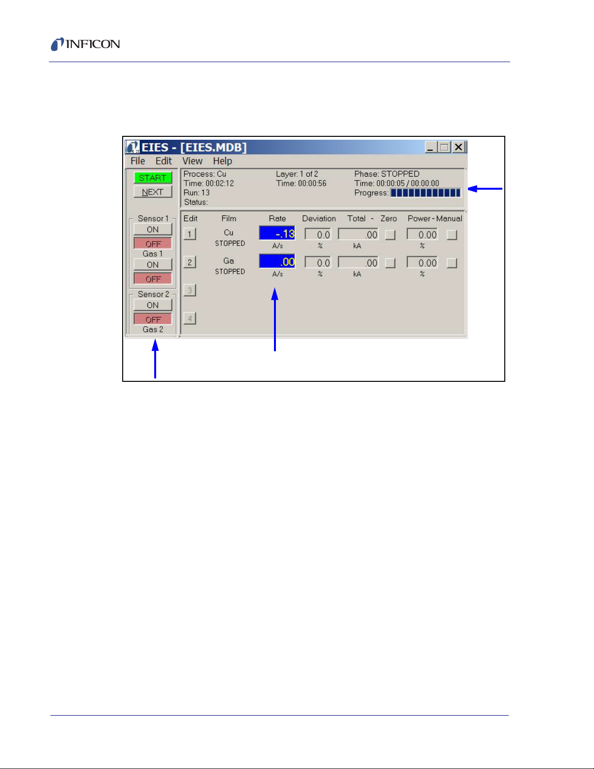
3.3 Main Screen
The EIES main screen, see Figure 3-5, consists of three panels and a menu bar.
The Status Panel (top) displays information on the active process. The Control
Panel (left) controls operation of the EIES-IV Guardian system. The Readings
Panel displays readings from each of the channels used by the active process
layer. Finally, the menu bar provides access to process recipe and instrument
setup functions.
Figure 3-5 EIES Main Screen
Guardian Co-Deposition Controller Operating Manual
3.3.1 Status Panel
Figure 3-6 Status Panel
IPN 074-517-P1D
Process: Name of the current process. Select the active process from the menu
File, Open Process.
Process Time: The accumulated time for this run of the selected process. Resets
to zero, then starts counting when the Start button is clicked.
Process Run: The number of times this process has been run. The run count can
be zeroed on the File >> DataLog screen.
Status: Displays error conditions and other status information.
Layer: Displays the current layer and the total number of layers in the active
process. Use the Next button on the Control Panel to select layers.
3 - 5
Page 58

Guardian Co-Deposition Controller Operating Manual
Start/Stop: Click Start to run the process. The Start control is disabled
if there are no communications with the EIES controller. When the
process is running, the top control displays Stop. Click Stop to stop the
process and set all outputs to 0. Press Start again to restart the layer.
Next: When the process is stopped, click Next to move to the next
process layer. The selected layer is displayed in the Status panel.
When Start is clicked, the process will start at the selected layer.
Reset: When a process is stopped, click Reset to abort the process
and reset the selected layer to 1.
Emission Controls: When first started, both the EIES instrument and
this program turn both sensors Off. Be sure Emission On is selected
when running the process or no EIES readings will occur. Turn sensor
Emission Off when not in use, or anytime the pressure exceeds 5x10⁻⁴
Torr. When Gas Compensating sensors are used, both the main
sensor and the Gas sensor should be on. The main and gas sensor
can be turned on/off simultaneously by holding the <Shift> key and
clicking the main sensor on/off.
When emission is On, the sensor's emission current is displayed with
a green background. If the leakage current reaches 70% of the
maximum allowed value, the background turns yellow. Maximum
Leakage is set in the Edit System dialog box, Sensor tab.
DataLog Control: Turns disk data logging on/off. Data is logged only
while the process is running. Edit data logging options in the File,
DataLog menu.
Layer Time: The accumulated time for this layer. Resets to 0 if the layer is stopped.
Phase: The current layer phase. Phases consist of pre conditioning (Ramp1,
Soak1, Ramp2, Soak2), Shutter Delay, Deposition, and post conditioning (Idle
Ramp). Additional phases, such as Stopped, Layer Stopped and Filter change are
also displayed.
Phase Time: Phase time is shown as ElapsedTime/TimeRemaining.
Progress: A graphical display of the percent complete for the current phase.
3.3.2 Control Panel
NOTE: To avoid accidental activation of the Start/Stop, Auto/Man, and Emission
controls you may need to press and hold the Ctrl key while clicking the
control. This feature can be disabled on the Display tab of the Edit System
screen.
Figure 3-7 Control Panel
IPN 074-517-P1D
3 - 6
Page 59

Guardian Co-Deposition Controller Operating Manual
3.3.3 Readings Panel— Process Mode
The readings panel, see Figure 3-8, has two display modes: Process and
Readings. Click View >> Process to see the process display. The Process display
mode shows process related information such as films, setpoints, and manual
operating controls. Only channels that are defined for the selected layer are
displayed. Use Edit >> System >> Display to select a 4 to 8 channel display.
Figure 3-8 Readings Panel Process Display
Edit Button: Click the Edit button to display the Edit Layer dialog box for the
channel. Consult the Edit Layer section of this manual for detailed layer edit
information.
Channel Film Display: Displays the film assigned to the channel and the current
phase of the channel. During deposition, also displays the current rate setpoint for
the channel.
Channel Rate: Displays the deposition rate reading for the channel. The EIES
detector module measures rate as a current. The current reading is converted to
Å/s (or the desired user units) using film parameters described in the Edit Film
section of this manual.
IPN 074-517-P1D
Deviation: The deviation of the measured rate from the desired rate setpoint.
Total: The accumulated Total thickness for the channel. Typically, rate is displayed
in Angstrom per second (Å/s) and Total is displayed in kÅ. For EIES detector
measurements, Total is calculated by summing each reading times the reading
period (then dividing by 1000 to convert to kUnits). For QCM inputs, Total is the
thickness returned by the quartz crystal. If a channel uses a SAM analog input,
Total is meaningless and is not displayed.
Zero (Total): Zeroes the accumulated total for the channel. To zero all channel
totals, hold the Shift key and click any channel Zero button.
Power: Displays the output power in percent of full-scale voltage.
3 - 7
Page 60

Guardian Co-Deposition Controller Operating Manual
Manual (Power): Switches the output power between PID loop control and manual
user setting. When pressed, the background of Manual power button and the
Power display turns green. The initial manual power value is the same as it was
when the Manual power button was pressed. In Manual power mode, you may type
a new power setting and press Enter to change the output power setting.
Click the Manual button again to return to auto (PID control) mode. If the process
is stopped, the power will be set to zero. If the process is running, the channel goes
immediately to the deposit phase, with power set by the PID control loop.
NOTE: Because the Edit Process dialog box allows editing of a layer's input and
output assignments, Manual Power can only be changed when the Edit
Process dialog box is closed.
3.3.4 Readings Panel—Ratio Mode
Figure 3-9 Ratio Mode
3 - 8
IPN 074-517-P1D
Click View >> Ratio to see the Ratio display. Refer to Figure 3-9.The Ratio display is
similar to the Process display except that the deviation readings are replaced with
the ratio of the channel’s reading to another channel. The other channel number is
shown below the ratio reading. Ratios are set up in the Edit Layer dialog box. See
Ratio Display Grid on page 3-20, for more information on channel ratios.
Page 61

Guardian Co-Deposition Controller Operating Manual
3.3.5 Readings Panel—Readings Mode
Click View >> Readings to see the readings display. See Figure 3-10. The
readings display mode shows unfiltered channel (detector), sensor, and QCM
readings.
Figure 3-10 Readings Panel Readings Display
3.3.5.1 Channel Readings
Each channel uses either two or three measurements to calculate the channel
current signal. The measurements used are:
PMTCurOn: The first measurement cycle measures the detector current with
sensor bias voltage on. This is a measure of the deposition flux, plus any
background signal from ambient light or the sensor filament. This measurement
also includes any broadband emission from other process gases.
IPN 074-517-P1D
PMTCurOff: The second measurement cycle measures the PMT current with
sensor bias voltage off. With bias voltage off, no electron emission occurs. Hence,
this is a measure of only background light.
PMTCurGas: The third measurement cycle is used only with INFICON's gas
compensating (GC) sensor. The GC sensor includes an element that is not
exposed to materials being deposited. It measures only the emission caused by
gases, especially water vapor and nitrogen (plus any background light as explained
above).
When the three measurements are completed, the channel readings are displayed
as:
Flux - Gas: equals PMTCurOn minus PMTCurGas.
3 - 9
Page 62

Guardian Co-Deposition Controller Operating Manual
CAUTION
Flux (nA): The flux plus gas signal, minus the background light.
Flux %: The % of full scale for the PMT and A/D converter circuits. Large values
risk overloading the measurement circuit. Small values cause poor signal to noise
ratios. Adjust the detector PMT voltage to achieve 30 to 80%.
Gas (nA): equals PMTCurGas minus PMTCurOff.
Gas %: The % of full scale for the PMT and A/D converter circuits of the GC sensor.
Bkg (nA): The ambient light signal.
3.3.5.2 Sensor Readings
Emission (Current): The sensor filament emits electrons to excite the valence
electrons of the measured material. Emission current is a measure of the electron
current emitted by the filament.
Refer to the label attached to your sensor or emitter
assembly package for correct emission current settings.
Do not operate 016-xxx series sensors with Yttria
filaments at Emission current greater than 2 mA. Instant
filament failure may occur! 016-xxx series sensors with
Thoria filaments may be operated at 4 mA emission.
Leakage (Current): As a sensor is used, material deposited on the sensor can
create leakage paths for the emission current. Leakage current is measured when
the bias on the filament is at +180 V, and no emission occurs. Values above 50%
of the Emission current indicate the sensor may need to be cleaned or replaced.
(Filament) Power: The power, in watts, supplied to the sensor filament. Seven
watts or less is normal. As the chamber pressure rises or the filament wears,
filament power and light intensity created by the filament will increase.
Fil(ament) Cur(rent): The current flowing through the filament. Around two to
three amps is normal.
Bias V(oltage): The voltage used to accelerate the emitted electrons. The factory
setting is 180 V.
Status: Fail indicates an open filament.
3.3.5.3 QCM Readings
The QCM grid is shown only when an SQM-242 or Q-pod QCM is installed.
Rate: The deposition rate (in Å/s) measured by each QCM sensor.
IPN 074-517-P1D
3 - 10
Page 63

3.3.6 Menu
Guardian Co-Deposition Controller Operating Manual
Thick(ness): The deposited thickness measured by each QCM sensor.
Zero: Click to zero the measured thickness, or Shift-click to zero all thickness.
Normally handled automatically by the EIES software when a new layer begins.
Frequency: The measured frequency of each QCM sensor. A negative value
indicates a sensor failure. A QCM requires a density, Z-Ratio, and tooling factor to
properly display rate and thickness. However, frequency is always displayed.
During deposition, the frequency will decrease. With no deposition the frequency
reading should be relatively stable.
Life%: The estimated percent life remaining on the crystal based on the spread
between the Max. (typically 6.0 MHz) and Min (typically 5.0 MHz) frequency range
values set for the Frequency.
SAM-242: The measured volts DC on an SAM-242 analog measurement card.
The menu along the top of the main screen provides access to functions for
building deposition processes, configuring the hardware for your vacuum system,
and data display.
The following sections detail the functions of each menu selection. For an overview
of program operation, click each menu selection, then read the corresponding
section in this chapter to understand the concepts involved.
Once you have worked through all menu items, go back to Chapter 2, Quick Start,
and build the sample process for a better operational understanding.
3.4 File Menu
NOTE: The current process must be stopped for the File menu to be available.
3.4.1 File >> Open Process
IPN 074-517-P1D
3.4.2 File >> Open and Save Database
Used to select a process from a list of all processes in the current database. If the
process selected is different than the current process, you are prompted to confirm
the change.
Open Database: Selects a database of processes to be used for deposition.
A single process database holds 25 processes. However, the number of process
database files is unlimited.
3 - 11
Page 64

Guardian Co-Deposition Controller Operating Manual
Save Database As: Saves the current process database to disk under a different
name in the default folder. The path cannot be changed. This is useful for saving
the process database for backup!, or for making trial changes without affecting your
working database. Process databases are saved in Microsoft Access format.
3.4.3 File >> Data Log On/Off
Turns disk data logging on/off. Data is logged only while the process is running.
This menu item duplicates the functionality of the main screen DataLog On/Off
control.
3.4.4 File >> Data Log Setup
Configures the disk data logging functions. Data is saved on disk in "comma
delimited" format for easy import into a spreadsheet for graphing and analysis.
Filename: Displays the name of the current DataLog file as explained below.
Figure 3-11 Datalog File Name
3 - 12
IPN 074-517-P1D
Select: To modify the DataLog file's name, click Select. A Save LogFile As dialog
box will be displayed. Enter a new filename and click Save. The file will be saved
in the default folder. To change the file path, the EIES software must be opened in
the Run as Administrator mode.
NOTE: To avoid delays in data acquisition, save to the hard disk, and transfer the
files to a USB stick later.
View: Opens the selected DataLog using Window's Notepad program.
Page 65

Log Interval: The elapsed time between data log entries. The data log is updated
only when the process is running.
Overwrite: The log file will be overwritten each time data logging is started by
pressing DataLog On on the main screen. Only the last run of the process is saved,
and it appears as FileName.LOG.
Append: Data is added to the end of the existing FileName.LOG file.
Run#: A data file, FileName_Run#.LOG, is written for each process run. Run# is
incremented each time the process is started. Enter a new Run# to reset the
counter.
Channel Data: Selects the channel(s) to log, and the data that is logged for each
channel.
Sensor Data: Selects the sensor(s) to log, and the data that is logged for each
sensor.
3.4.4.1 Format of the DataLog file
Start Log Process Name Run:364 Date Time
Layer: 1 Setup:
Chan:1 Film:Se Rate:000.000 Units:Å/s Total:005.500 TimeSP:00:05:00
Chan:2 Film:Press Mon. Rate:000.000 Units:Torr Total:000.000 TimeSP:00:00:00
Chan:3 Film:Temp Rate:000.000 Units:DegC Total:000.000 TimeSP:00:00:00
Chan:4 Film:Se Rate:000.000 Units:Å/s Total:005.500 TimeSP:00:05:00
Time, Phase, Chan#, Rate, Dev Total Power
00:00:05, RAMP 1, CH1:, 0.00, 0.0, 000.0, 00.0,
00:00:10, RAMP 1, CH1:, 0.00, 0.0, 000.0, 00.0,
Guardian Co-Deposition Controller Operating Manual
How to Graph data in Microsoft Excel®:
Start the Excel program and select File >> Open. In the File Open dialog box,
select Files of Type: All Files. Navigate to the proper folder and click on the data
log you want to open, then click Open.
In the Excel Text Import Wizard select Delimited, then Next. Select Comma as the
IPN 074-517-P1D
delimiter. Check Treat Consecutive Delimiters as One. Select Text Qualifier
{None}. Click Finish to open the DataLog in Excel.
To graph the data, select the column with time, then each of the channel data
columns you wish to graph. For example, to graph channel rates select column A
(time), column D (Chan1 Rate), and column I (Chan2 Rate). Click Insert, Chart.
In the Chart Wizard select Line chart, then Next. The chart should appear with the
rates graphed against time. There will be some extra entries along the time axis;
you are welcome to clean this up, but the graph will be quite usable with just these
few steps.
3.4.5 File >> Print Screen
Sends a copy of the main screen to the printer selected in the Page Setup menu.
3 - 13
Page 66

Guardian Co-Deposition Controller Operating Manual
3.4.6 File >> Page Setup
Provides printer selection and page orientation for the Print Screen function.
3.4.7 File >> Exit
Stops the current process, turns off Emissions, and exits the EIES program.
3.5 Edit Process
The Edit Process dialog box provides the functions needed to create and edit thin
film deposition processes. A few definitions will be helpful as you use this manual.
A Process is a sequence of Layers of different Films.
Each Layer establishes the desired rate and thickness of the deposited Film.
A Film defines the physical material being deposited, plus all of the instrument
setup parameters associated with that material.
Multiple films deposited simultaneously are known as a CoDeposition (or
CoDep) Layer.
The Edit Process dialog box, see Figure 3-12, displays the 25 processes of the
current database in a "treeview" display (similar to the file folders of Windows
Explorer). Click the [+] beside a process to show the layers in that process.
Figure 3-12 Edit Process Dialog Box
Layers are shown as Layer# Channel# Output# FilmName. Channel number is
the EIES channel used for monitoring deposition. Codeposited layers are marked
as CoDep and listed similarly.
IPN 074-517-P1D
3 - 14
Page 67

Guardian Co-Deposition Controller Operating Manual
NOTE: The Edit Process dialog box can only be accessed when the process is
stopped.
To add layers to a process, click any existing layer (in any process) then click Copy.
See Figure 3-13. This places a copy of the highlighted layer on the clipboard, and
enables the Paste button.
Figure 3-13 Edit Process Highlighted Layer
There are four Paste options:
Below: Insert the clipboard layer below the highlighted layer.
Above: Insert the clipboard layer above the highlighted layer.
Replace: Replace the existing layer with the clipboard layer.
CoDep: Insert the clipboard layer as a codeposition layer of the highlighted layer.
Now click a layer in the process where you want to paste the clipboard layer, and
click Paste.
IPN 074-517-P1D
To copy an entire process to the clipboard, click on the process, then click Copy.
Click another process and click Paste to replace it with the clipboard process. Be
careful when pasting processes, there is no undo function!
To edit a layer's parameters, click the layer, then the Edit button. The Edit Layer
dialog box for the selected layer is displayed. See the next section for detailed
information on using the Edit Layer dialog box.
3 - 15
Page 68

Guardian Co-Deposition Controller Operating Manual
3.6 Edit Layer
A Layer establishes the desired rate and thickness (plus a few other parameters)
for a deposited film. The Edit Layer dialog box, see Figure 3-14, can be accessed
by clicking a channel Edit button on the Main Screen, or by highlighting a layer and
clicking Edit on the Edit Process dialog box.
Figure 3-14 Edit Layer Dialog Box
3 - 16
NOTE: The Channel and Output settings can only be changed by accessing Edit
Layer from the Edit Process dialog box when the process is stopped.
Channel (1 to 8) : The channel that displays this layer's readings on the main
screen. Typically this is the same as the detector input channel (labeled MODULE
1 to MODULE 8) on the Guardian controller. If a QCM or analog input is used as
the input for this layer, it is selected on Channel Input of the Film Cal. tab (see
section 3.7.3 on page 3-28).
Output (1 to 8): The Guardian Control Output that is used when depositing this
layer.
Film: This is the most important layer parameter. It establishes the material to be
deposited, and many of the instrument setup parameters associated with that
material. Select the desired film from the Film drop-down menu. This selection
determines the values that are displayed on the Film and Film Cal. tabs of the Edit
Layer dialog box.
IPN 074-517-P1D
Page 69

3.6.1 Layer Grid
Parameters on the Layer tab are unique to this layer. Those on the Film and
FilmCal tabs pertain to any layer using the film. Pause the mouse over any
parameter to see a brief description. Edit a parameter by clicking in the parameter's
value cell, then typing a value, or by selecting a value from a drop-down menu.
Time values may be entered in hh:mm:ss format, or as whole seconds (which are
automatically converted to hh:mm:ss format).
When you click in another cell, or press Enter, the parameter value is checked for
validity and stored in the process database. If the process is running, the
parameters are also sent to the EIES Controller.
Setpoint Å/s: The desired deposition rate for the layer. 0.00 causes the layer to be
skipped.The PID loop will control the channel output voltage during deposition to
achieve the setpoint. Rate is typically displayed in Angstroms per second (Å/s).
This value can be modified by user-supplied Units conversion factors consisting of
a Multiplier and Offset, found on the Channel tab. The displayed deposition rate is
calculated as:
Rate (Å/s) = (ChannelRate - QCMCalZero - xChan1 - xChan2 ) x QCMCalFactor [1]
Guardian Co-Deposition Controller Operating Manual
- or -
Rate (User Units) = (Rate(Å/s) x UserMultiplier) + UserOffset [2]
Endpoint kÅ: The desired material thickness for the layer. 0.00 causes the layer
to be skipped.When Endpoint is reached, deposition ends for the layer. The value
is typically in kÅ, but may be scaled by the user units as described in Setpoint
above. The displayed thickness is calculated as:
Endpoint (kÅ) = Sum of (Rate(Å/s) x Measurement Period / 1000) [3]
- or -
Endpoint (UserUnits) = Sum of (Rate(UserUnits) x Measurement Period / 1000) [4]
EndSetPt kÅ: When EndSetPt is reached, the EndSetPt relay is activated. 0.00
disables the function. However, deposition continues until EndPoint thickness is
IPN 074-517-P1D
reached.
Time SetPt hh:mm:ss : Closes the Time Setpoint relay after a certain time up to
the maximum value of 23:59:59. If Time SetPt occurs before EndPoint thickness is
reached, the layer stops. A time SetPt value of 00:00:00 disables this function.
3 - 17
Page 70

Guardian Co-Deposition Controller Operating Manual
Start Mode: A layer may start in three ways. In Auto, the layer starts immediately
upon completion of the previous layer. In Manual, the layer waits for the user to
click the Start button. If there are CoDep channels, they will also wait for a user
Start if any channel Start Mode is set to Manual.
Constant start is a special case used for controlling constant process variables
such as temperature and pressure. Constant start holds the channel at the rate
setpoint throughout the process. Only pressing Reset or completing the process
will set the channel output to zero.
Start Prompt: Allows a user prompt to appear at the beginning of a Manual Start
layer. If any text is entered in this parameter, it shows as an on-screen prompt with
two user choices: OK to start the layer, or cancel to stop the layer. This is useful for
prompting for operator actions such as opening valves or checking settings.
3.6.2 Rate Ramps Grid
Rate ramps change the initial rate setpoint. Each rate ramp has a starting
thickness, an elapsed time to ramp to the new rate setpoint, and a new Ramp#Rate
setpoint. Each layer can have two rate ramps.
NOTE: These rate ramps alter the rate during deposition. Do not confuse these
ramps with the preconditioning ramp/soak power ramps on the Film tab.
Ramp1 Start kÅ: The thickness that triggers a timed ramp to a new rate. Setting
Ramp1 Start to zero disables the rate ramp. Ramp1 Start should be less than the
layer Endpoint, otherwise the rate ramp is ignored.
Ramp1 Rate: The new deposition rate for the layer.
Ramp1Time: The time to ramp to the new Ramp1 Rate setpoint. If the rate ramp
is too fast, a PID control error may be generated.
Ramp2 Start kÅ: The thickness that triggers a timed ramp to a new rate. Setting
Ramp2 Start to zero disables the rate ramp. Ramp2 Start should be greater than
Rate1 Ramp and less than the layer Endpoint, otherwise the rate ramp is ignored.
Ramp2 Rate: The new deposition rate for the layer.
Ramp2Time: The time to ramp to the new Ramp2 Rate setpoint. If the rate ramp
is too fast, a PID control error may be generated.
IPN 074-517-P1D
3 - 18
Page 71

Guardian Co-Deposition Controller Operating Manual
3.6.3 X Chan (Cross Channel) Tab
Parameters on the X Chan tab are unique to this layer. Those on the Film and
FilmCal tabs pertain to any layer using the film. Each EIES detector channel
measures an emission line that is unique to the material. However, other materials
being evaporated at the same time may have emission lines that overlap the
bandwidth of the desired material's filter. In that case, a portion of the unwanted
channel's signal must be subtracted from the reading. Cross Channel Calibration
(xChan) establishes the amount of the unwanted signal(s) to subtract.
Figure 3-15 Cross Channel Grid
IPN 074-517-P1D
The channel listed at the top left of the form, 1 in the example, is the channel being
measured. A percent of the channels in the grid will be subtracted from that
measurement channel. Up to four cross channel readings may be subtracted.
Cross channels must be different from the measurement channel.
xChan #: The readings of the channel selected at the top of the form will be
modified by subtracting a portion of each xChan# readings. Select value None for
any unused xChan Cross channels.
xChan%: The percent of the xChan signal to be subtracted from the measurement
channel reading. 0.00 disables the function.
XChan Subtract: Select Current or Rate to be subtracted
3 - 19
Page 72

Guardian Co-Deposition Controller Operating Manual
Current: A percent of each xChan Detector current is subtracted, before any
material calibration, tooling factors, etc. have been calculated. The advantage
of this method is that a change in the xChan calibration factors does not impact
the amount of xChan compensation.
Rate: A percent of each xChan Detector rate is subtracted, after material
calibration, tooling factors, etc. have been calculated. This method allows
recalibration of an xChan to alter the amount of xChan compensation.
3.6.4 Ratio Display Grid
In addition to cross channel calibration, the xChan tab of the Edit Layer dialog box
allows setup of the Main Screen Ratio Display.
Figure 3-16 Ratio Display
3 - 20
IPN 074-517-P1D
Channel Multiplier: The channel reading is multiplied by this value before the ratio
is calculated. Useful for scaling or calibrating to a desired value. 0.00 disables the
function.
Ratio Channel #: Channel used for (denominator of) ratio calculation.
Ratio Channel Multiplier: Multiplies ratio channel reading by this amount.
0.00 disables the function.
Page 73

Ratio Filter: The number of readings averaged for the ratio display. 0 disables the
function. Because we are dividing two channels, and possibly multiplying their
readings, a larger filter may be desirable.
The value displayed is:
Ratio Display = (Chan. Reading x Chan. Multiplier) /
(Ratio Chan Reading x Ratio Chan Multiplier) [5]
3.6.5 Edit Layer Film Tab
NOTE: The parameters on the Film tab are Film parameters. They are determined
by the Film selected for a layer. If you change the parameters on either of
these tabs, they will be changed for any layer (in any process) that uses
the selected film.
Figure 3-17 Edit Layer Film display
Guardian Co-Deposition Controller Operating Manual
IPN 074-517-P1D
3 - 21
Page 74

Guardian Co-Deposition Controller Operating Manual
3.6.5.1 Deposit Grid
P Term: Sets the gain of the control loop. High gains yield more responsive (but
potentially unstable) loops. Try a low value then gradually increase/decrease to
respond as desired to step changes in setpoint.
I Term: The integral term controls the time constant of the loop response. A small
I term, say 0.5 to 1 seconds, will smooth the response of most loops. An I value of
0 effectively disables PID control.
D Term: The differential term causes the loop to respond quickly to changes. Use
0 or a very small value to avoid oscillations.
Shutter Delay: Shutter delay sets the time allowed for a channel to achieve
deposition control. Shutter delay assures that the channel reaches a certain
accuracy before deposition begins. If the accuracy is not reached, the process
halts. If accuracy is reached and maintained for 5 seconds before Shutter Delay
time, the substrate shutter opens and deposition begins. Set Shutter Delay to zero
to disable this function.
Shutter Capture: Sets the shutter delay rate accuracy that must be reached for
deposition to begin.
Error Action: If the control loop cannot maintain the desired Setpoint (due to loss
of source material, excessively high rate ramps, or equipment malfunction) a
control error occurs. When an error condition occurs, three actions are possible:
Ignore the error and let the PID loop attempt to maintain rate control based on
"control percentage."
Stop the layer and allow the user to fix or manually control deposition.
Hold deposition at the last good Power setting to "estimate" rate and thickness.
For best results, use shutter delay to assure adequate process control before
entering the deposition phase.
Control Error: The rate error in percent that must not be exceeded during
deposition to prevent a control error. Set Control Percent to zero to disable this
function.
Max Power: The maximum output power allowed for the film. Max Power controls
the maximum % of the full scale voltage that can be used by this film in any process
phase.
Slew Rate: The maximum power change allowed on an output, per second. If rate
ramps or PID power requirements exceed this value, an error occurs.
Full Scale: The maximum output voltage for your deposition supply's input range.
Values from 0 to +/-10 V are possible.
IPN 074-517-P1D
3 - 22
Page 75

3.6.5.2 Condition Grid
Ramp1 Power: The power level desired at the end of the Ramp 1 phase, in % of
full scale.
Ramp1 Time: The time to ramp linearly from the initial power to the Ramp 1 Power.
If multiple channels have preconditioning programmed, the start of Ramp1 may be
delayed so that the Soak2 phase for all channels ends at the same time.
Soak1 Time: The time the output remains at Ramp 1 Power. At the end of Soak 1
Time, the Ramp 2 phase starts.
Ramp2 Power: The power level desired at the end of the Ramp 2 phase, in % of
full scale.
Ramp2 Time: The time to ramp linearly from Ramp1 Power to Ramp2 Power.
Soak2 Time: The time the output remains at the Ramp 2 power level. At the end
of Soak 2, all channels will enter the Shutter Delay phase.
Idle Power: Idle power usually holds the material at a state that is ready for
deposition, typically the same as Ramp 2 power if the material is to be used in a
subsequent layer.
Guardian Co-Deposition Controller Operating Manual
Idle Ramp: The time to ramp linearly from deposition power to Idle Power.
IPN 074-517-P1D
3 - 23
Page 76

Guardian Co-Deposition Controller Operating Manual
3.6.6 Edit Layer Film Cal
NOTE: The parameters on the Film Cal. tab are Film parameters. They are
determined by the Film selected for a layer. If you change the parameters
on either of these tabs, they will be changed for any layer (in any process)
that uses the selected film.The Film Cal. tab displays parameters that
control the calibration and display of channel readings. Depending on the
Input type selected, all of the parameters listed may not be available.
Figure 3-18 Edit Layer Film Cal Display
3.6.6.1 Calibration Grid
Input: Selects which sensor is used for measurement of the channel. Select EIES
to use the selected EIES detector channel input. Select a QCM input to use an
SQM-242 card or Q-pod sensor for deposition measurement. SAM uses the
SAM-242 analog card inputs for measurement.
PMT Volts: 0 to 1250. Sets the bias voltage (gain) of the channel's photomultiplier
tube. The emission from different materials may require different PMT voltages to
optimize performance. Typical values range from 600 to 700. Use the lowest
setting that provides adequate signal. As PMT voltage is increased, PMT noise is
also increased, reducing the signal to noise ratio.
3 - 24
IPN 074-517-P1D
Page 77

Guardian Co-Deposition Controller Operating Manual
Cal Gain: The multiplier used to convert EIES current measurements to calibrated
rate/thickness. You may enter a value manually, or the value is updated each time
QCM Calibrate is clicked.
Cal Zero: Due to gas background emission, there may be an EIES rate reading
when there is no deposition. Enter the background rate to correct EIES rate to zero.
User Multiplier: This value is multiplied by the calibrated rate (in Å/s) to convert to
User Units on the main screen rate display. Set the multiplier to 1 to display
readings in Å/s. Also used with the SAM-242 analog card to convert volts to
different units.
User Offset: Value subtracted from the calculated rate (in Å/s) to convert to User
Units shown in the channel's reading display. Set the offset to 0 to display readings
in Å/s.
User Units: The units displayed below the channel reading on the main screen.
Typically Angstroms per second (Å/s).
Integer Digits: The number of integer digits (left of the decimal point) displayed in
the channel's rate display. The channel rate display can show four total digits, plus
the decimal point and sign. If IntDigits plus DecDigits is greater than four, the
left-most digits will not be seen.
Decimal Digits: The number of decimal digits (right of the decimal point) displayed
in the channel's rate display. The channel rate display can show four total digits,
plus the decimal point and sign. If IntDigits plus DecDigits is greater than four, the
left-most digits will not be seen.
Exponent: Scales the channel rate display by powers of 10. For example, select 3
to display kilo-units or -3 to display milli-units.
Filter: The number of readings that are averaged for display on the main screen.
IPN 074-517-P1D
3 - 25
Page 78

Guardian Co-Deposition Controller Operating Manual
Substrate Thick
Sensor Thick
-------------------------------------
Correct Tooling
Current Tooling
--------------------------------------=
Over 100%
Under 100%
3.6.6.2 QCM Grid
Cal QCM#: Establishes which QCM sensor is used to calibrate this channel's EIES
detector.
Density: Sets the QCM density for this material. Material density has a significant
impact on deposition calculations when a QCM is used for calibration or control.
See Appendix B for common material densities.
Z-Factor: Sets the QCM Z-Factor or Z-Ratio, the measure of a material's effect
with increased thickness on QCM accuracy. See Appendix B for common material
Z-ratios.
Tooling %: Adjusts for deposition rates measured by the QCM that differ from the
substrate deposition rate. A higher tooling value yields higher rates. See Figure
3-19. For example, if the sensor sees only 50% of the substrate rate, set Tooling to
200%. Setting Tooling to 0% causes a sensor to be ignored for this film.
The defining equation is:
[6]
Figure 3-19 Tooling Value
Substrate
Substrate
Tooling
Cal Accuracy%: The EIES channel calibration accuracy to be achieved during
QCM calibration. A lower value means higher accuracy is required.
Cal Interval: The time interval between automatic QCM calibration of the EIES
channel. Set to 00:00:00 to disable periodoc automatic calibration.
Tooling
IPN 074-517-P1D
3 - 26
Cal Sample: The time the QCM shutter remains open for QCM calibration of the
EIES channel.
Calibrate: Starts a QCM calibration cycle as defined by Cal Accuracy, Cal Interval
and Cal Sample. Shown only when the Layer version of this dialog box is selected.
Page 79

3.7 Edit: Film
A Film sets the parameters for the material to be deposited in a layer, the control
loop tuning, pre/post conditioning, and many of the instrument hardware
parameters associated with that material.
Figure 3-20 Edit Film Dialog Box
Guardian Co-Deposition Controller Operating Manual
The Film tab displays the deposition and pre/post conditioning parameters for the
selected film. The Film Calibration (Film Cal.) tab contains instrument, display, and
QCM parameters.
NOTE: Changing any parameters under the Film and Film Cal tabs also changes
those parameters on the layer using the film.
IPN 074-517-P1D
Pause the mouse over any parameter to see a brief description. Edit a parameter
by clicking in the parameter's value cell, then typing a value, or by selecting a value
from a drop-down menu. Time values may be entered in hh:mm:ss format, or as
whole seconds (which are automatically converted to hh:mm:ss format).
When you click in another cell, or press Enter, the parameter value is checked for
validity and stored in the process database. If the process is running, the
parameters are also sent to the EIES.
Rename: Gives a meaningful name (often the material) to the film.
Copy: Copy the film parameters to the clipboard.
Paste: Select another film and click Paste to replace it with the clipboard film
parameters. Be careful when pasting films, there is no undo function!
3 - 27
Page 80

Guardian Co-Deposition Controller Operating Manual
3.7.1 Deposit Grid
Refer to section 3.6.5.1.
3.7.2 Condition Grid
Refer to section 3.6.5.2.
3.7.3 Film Cal(ibration) Tab
Refer to section 3.6.6.
Figure 3-21 Edit Film Calibration Tab
3.7.3.1 Calibration Grid
Refer to section 3.6.6.1.
3.7.3.2 QCM Grid
Refer to section 3.6.6.2.
3 - 28
IPN 074-517-P1D
Page 81

3.8 Edit >> System
The Edit System dialog box contains parameters that apply to all of the processes
in a process database. The settings are arranged on a tabbed dialog box.
3.8.1 Channel Tab
Figure 3-22 Edit System Channel Tab
Guardian Co-Deposition Controller Operating Manual
Sensor: Must be set to the EIES sensor (standard or gas compensating) that the
channel detector module is attached to.
Update: The rate at which readings are returned from the EIES detector. The
detector module takes 1000 readings per second and averages readings between
updates.
Cal Rdg (Readings): The number of detector readings averaged to calculate the
calibration constants. The total calibration time for a channel is 4 times the Cal.
Readings divided by Update.
IPN 074-517-P1D
Start: Starts calibration of the selected EIES detector. Depending on the number
of readings and the channel update interval, calibration may take several seconds.
NOTE: This calibrates the detector electronics assuming no current from
deposition. It is different from QCM calibration, which calibrates detector
readings relative to a QCM while deposition is occurring. Allow a one hour
warm-up for the PMT to reach optimum stability prior to calibrating.
Calibrate Channel: The detector Module channel selected for calibration.
3 - 29
Page 82

Guardian Co-Deposition Controller Operating Manual
CAUTION
3.8.2 Sensor Tab
The format of the Sensor tab is determined by the type of sensor used. Figure 3-23
is shown when a gas compensating (GC) controller is used. For non-GC
controllers, only Emission SetPt and Maximum Leakage fields are visible.
Figure 3-23 Edit System Sensor Tab
Refer to the label attached to your sensor or emitter
assembly package for correct emission current settings.
Do not operate 016-xxx series EIES sensors with Yttria
filaments, see New 016-Series Sensor Exploded on page
5-4, at settings greater than 2 mA. Instant filament failure
may occur! 016-xxx sensors with Thoria filaments may be
operated at 4 mA emission.
When co-depositing materials, you may need to find a balance between signal
strength and noise for multiple channels. Changing the detector PMT voltage (Edit
Layer, Film Cal. tab) can help match the materials to the selected sensor emission
current.
Max. Leak(age): As material is deposited on a sensor, the leakage current
increases until the Guardian can no longer adequately control emission current.
This field establishes the leakage current that will stop deposition.
When leakage current reaches 70% of Max. Leakage, the background of the
emission current reading on the main screen turns yellow, see section 5.3, Sensor
Maintenance, on page 5-2.
IPN 074-517-P1D
3 - 30
Page 83

Gas Cal: INFICON's gas compensating sensors provide a measurement of the
emission caused by background gases. The gas calibration factor is used to null
this portion of the signal from the main flux sensor measurements. If the EIES rate
reading with no evaporation is negative, decrease the Gas Cal. parameter until the
rate averages near zero. If the rate reading is positive with no evaporation,
increase the Gas Cal. parameter until the reading averages near zero.
Enable Gas Sensors: Click to select the gas compensating feature. Requires gas
compensating (GC) sensors.
3.8.3 QCM Tab
NOTE: See the SQM-242 Card or Q-pod Manual for detailed QCM installation and
None: No QCM inputs are used.
SQM_242: INFICON SQM-242 card is used for QCM measurements. DLL shows
the status of the SQM-242 card's Windows drivers. DLL return values of 9XX
indicate a card installation error. The firmware revision of the installed SQM-242
and SAM-242 cards are also listed. A value of 0 indicates the card is not installed.
Figure 3-24 Edit System QCM Tab
Guardian Co-Deposition Controller Operating Manual
troubleshooting instructions.
IPN 074-517-P1D
3 - 31
Page 84

Guardian Co-Deposition Controller Operating Manual
Q-pod: INFICON's Q-pod transducers are used for QCM measurements. The
serial number and revision of each installed Q-pod is shown.
Figure 3-25 QCM Tab Q-pod Selection
Period: Sets the QCM measurement period between .2 seconds (5 readings per
second) and 2 seconds. A longer period gives higher reading accuracy, especially
at low rates.
Max/Init/Min Frequency: The frequency values for the quartz crystal sensors
used as inputs to the QCM. Typical values are Max=6.1, Init=6.0, Min=5.0. Sensor
readings outside the min/max values cause a Sensor Fail error.
IPN 074-517-P1D
3 - 32
Page 85

3.8.4 Digital I/O Tab
Figure 3-26 Edit System I/O Tab
Guardian Co-Deposition Controller Operating Manual
3.8.4.1 Relay Assign
To assign a deposition event to a relay, click the Relay #, then select the desired
event from the drop-down menu. The Set, Clear, and Clear All buttons manually
operate the selected relay. A description of each relay event follows:
Process Running and Stopped Relays: These relays indicate the overall status
of the process. The Process Running relay closes as soon as Start is selected (by
front panel or digital input), and opens when Stop is selected. The Process Stopped
relay contacts behave in the inverse manner.
Deposit Phase Relay: This relay indicates that Guardian is in the deposit phase
of a film. If shutter delay is enabled, this relay will close at the end of the shutter
IPN 074-517-P1D
delay.
Pre-Cond Phase Relay: This relay closes for the preconditioning phases (Ramp1,
Soak1, Ramp2, Soak2) of a film.
Soak Hold Phase Relay: This relay closes for the duration of the Idle Ramp phase.
Process Active Relay: This relay action is similar to the Process Running relay,
except it will open if the process is temporarily halted for any reason, e.g., Manual
Power.
Manual Mode Relay: Closes when the program is placed in Manual mode.
Max Power Relay: Closes when any control voltage output is at the programmed
maximum power level.
3 - 33
Page 86

Guardian Co-Deposition Controller Operating Manual
Time Setpoint Relay: This relay will close when Run Time equals the Time
Setpoint.
Channel Relays 1 to 8: These relays control EIES sensor shutters. They close
during shutter delay and deposition.
Source Relays 1 to 8: These relays control the Shutter that covers the deposition
source. They close during deposition.
QCM Relays 1 to 4: These relays control QCM sensor shutters. These relays
close during shutter delay and deposition.
3.8.4.2 Input Assign:
To assign a deposition event to an input, click the Input #, then select the desired
event from the drop-down menu. Click the Read button to read the current state of
the highlighted input. A brief description of each input event follows:
Start Process: Triggering this input is the same as pushing the Start Process
button.
Stop Process: Triggering this input will abort the process.
Start Film: Triggering this input starts the current film.
Stop Film: Triggering this input will stop the current film.
Emission 1/2 Interlock: Set this input to inhibit turning on emission from the front
panel.
Emission 1/2 On: Turns sensor 1 or 2 emission On
Emission 1/2 Off: Turns sensor 1 or 2 emission Off
End Channel 1 to 8: Stops deposition phase and goes to idle phase
.
Calibrate Channel 1 to 8: Starts calibration of the selected channel.
NOTE: Input 5 is hardware assigned to the General Emission interlock function.
IPN 074-517-P1D
3 - 34
Page 87

3.8.5 Comm Tab
The Comm Tab sets up communications between the EIES program and the
Guardian controller. Settings are made in two panels, Guardian and External.
Figure 3-27 Edit System Comm Tab
Guardian Co-Deposition Controller Operating Manual
3.8.5.1 Guardian
Comm Port: . . . . . . . . . . . . . . . . . . Disabled, Com 1 to 9, Ethernet
Selects a computer RS-232 serial port or Ethernet port for communicating with the
Guardian controller. If a comm port is not installed, or is being used by another
program, an error message will be displayed, otherwise, the Version # for the
controller firmware is shown.
If Ethernet is selected as the Comm Port, Port and IP Address selection fields will
appear:
Ethernet Port: Shows the current IP port and allows changing it. Default
IPN 074-517-P1D
Ethernet Port is 2101.
IP Address: Displays the current IP address and allows changing it. The
default Guardian IP address is 192.168.1.200. For a direct connection, set the
computer’s IP address to be the same as the Guardian’s except the last group
must be different. For example, to communicate with a Guardian at the default
address, set the computer to 192.168.1.100.
3 - 35
Page 88

Guardian Co-Deposition Controller Operating Manual
Show Comm: Displays a diagnostic screen that shows communications between
the EIES program and the Guardian controller. See Figure 3-28.
For troubleshooting purposes, you can manually send ASCII commands to the
EIES instrument and see the response. For example, send an @ to see the EIES
instrument version.
Figure 3-28 Guardian Communications Dialog Box
3.8.5.2 External
This option is not supported, set External Communication Comm Port to Disabled,
(see Figure 3-27).
3 - 36
IPN 074-517-P1D
Page 89

3.8.6 Display Tab
Figure 3-29 Edit System Display Tab
Guardian Co-Deposition Controller Operating Manual
Show 1 to : Sets the main screen to display 4 or more (max. 8) channels of EIES
data. The minimum number of channels is four to allow adequate space on the left
control panel.
Update Frequency: The frequency, 1,2, 5 or 10 at which the main screen readings
are updated per second.
Require Ctrl Key: When checked, you must press and hold the <Ctrl> key to
activate main screen controls. This helps prevent accidental operation.
Colors: Sets the colors of several of the main screen display elements. Click
Default to return the colors to their default settings.
IPN 074-517-P1D
3 - 37
Page 90

Guardian Co-Deposition Controller Operating Manual
3.9 View Menu
3.9.1 Process, Ratio, Readings
The Process, Ratio and Readings menu items are described at section 3.3.3 on
page 3-7, section 3.3.4 on page 3-8 and section 3.3.5 on page 3-9, respectively.
The check mark indicates which one is active. Click on the title to select that
display. In addition, four graphs may be viewed as described below.
3.9.2 Graph Selection
The EIES program supports four independent graphs. Initially they are shown on
the View menu as 1. Rate (see Figure 3-30), 2. Deviation, 3. Power, and
4. Total. The titles may be changed.
To size a graph, click and drag the form's border. The size and location are
automatically stored on exit from the program.
Figure 3-30 Rate Graph
3 - 38
IPN 074-517-P1D
Close: Closes the selected graph display.
Pause/Run: Click pause to temporarily stop the graph from displaying data. Click
Run to resume graphing.
Setup: The graph's name and data, as well as many other setup parameters, can
be changed on the Graph Setup screen. Graph setup is detailed in section 3.9.2.1,
Graph Setup, on page 3-39.
Print: Prints the graph to the system printer.
Help: Displays the graph help screen.
Page 91

3.9.2.1 Graph Setup
The Graph Setup dialog box provides access to the most commonly used graph
setup parameters. It also provides total control of graph setup, using the Advanced
Property Editor.
Figure 3-31 View Setup
Guardian Co-Deposition Controller Operating Manual
Title: The caption that appears at the top of the graph window and on the main
dialog box's Graph menu. However, the graph's setup properties are always stored
on disk as Graph 1 to Graph 4.
Data: Selects which of the seven possible data sources are used for this graph —
Rate, Filtered Rate, Rate Ratio, Dev(iation), Power, Total, or Sensor data. Sensor
data displays the main flux and gas compensating signals for each detector.
Help: Shows the graph setup help dialog box if the Advanced checkbox is not
checked. If the Advanced checkbox is checked, shows advanced Property Editor
help.
IPN 074-517-P1D
Close: Closes the Graph Edit dialog box.
3.9.2.1.1 Show Channel — Axis
Channel 1 to 8: Selects the EIES channels to be graphed. If the channel is used
in a layer, and the channel is checked here, its data is displayed. If the channel is
not assigned to a layer, the show channel selection for that channel is ignored.
Left: The data for this channel is referenced to the left axis of the graph. When
Sensor Data is selected (see above) the left axis shows the main flux sensor.
Right: The data for this channel is referenced to the right axis of the graph. When
Sensor Data is selected (see above) the right axis shows the gas compensating
sensor.
3 - 39
Page 92

Guardian Co-Deposition Controller Operating Manual
3.9.2.1.2 Y Axis Left/Right
Caption: The caption shown along the graph's left or right axis.
Min: The minimum value for the Y axis.
Max: The maximum value for the Y axis.
x.xxEx: Shows the selected Y axis values in scientific format (i.e., 2.00E-4).
Log10: Shows the selected Y axis in Log base 10 values.
3.9.2.1.3 X Axis
Range: Sets the width of the X axis in seconds, minutes, or hours. The X axis
scrolls as needed to display the current readings, maintaining this range. If the
range is set to zero, the program will select the X axis range.
Units: Show the X axis in seconds, minutes, or hours.
Scroll: Selects the % of the graph to scroll when data overruns the X axis
maximum value. Select scroll to smoothly scroll the graph.
Points: Enter the number of points to be plotted on the graph.
Graph on Top: When selected, the graph will be shown above other windows.
When not selected, other windows may hide the graph. Use View on the main
screen to show all opened graphs.
Advanced: The program's graph setup dialog box is adequate for most users.
However, the graphing control used by the EIES program is much more powerful
(and potentially confusing). By checking Advanced, you override this setup screen
and use the graph control's advanced Property Editor to customize the graph.
Before making changes in the advanced Property Editor, you should make a
backup of the original Graph#.OC2 — where # is the number before the graph
name in the View menu.
The advanced Property Editor is accessed by right-clicking on the graph dialog box
you want to edit (not this Graph Setup dialog box), then left-click on Properties. To
save advanced Property Editor changes, select the Control tab, then click Save to
overwrite the Graph#.OC2 file.
To view Property Editor Help, click the Help button on the Graph Setup dialog box,
not the Help button on the Advanced property editor, it is not functional.
IPN 074-517-P1D
3 - 40
Page 93

4.1 Introduction
Chapter 2 provided a "quick start" guide to installation and operation of the
Guardian system. This chapter provides more detail on mechanical and optical
installation requirements, and our recommendations to help you achieve the best
results from your Guardian system.
Optical components (filters, lenses, light tubes, beam-splitters, fiber optics, etc.)
are a critical part of the EIES system. INFICON does not manufacture any of these
components, but we have an on-going program of evaluating optical components
for use with EIES systems. Some components that meet specific performance
criteria are sold with our Guardian systems. In many cases, however, you will want
to evaluate and purchase components to meet your own specific requirements.
The companies listed below are excellent sources for lenses, filters, and other
optical components needed to complete your EIES system installation.
Guardian Co-Deposition Controller Operating Manual
Chapter 4
Installation
CeramOptec Industries
515A Shaker Road
East Longmeadow, MA 01028
413-525-0600
www.ceramoptec.com
Edmond Scientific
101 E. Gloucester Place
Barrington, NJ 08007
800-363-1992
www.edmundoptics.com
Omega Optical
IPN 074-517-P1D
21 Omega Dr., Delta Campus
Brattleboro, VT 05301
802-254-2690
www.omegafilters.com
Thorlabs
435 Route 206 Box 366
Newton, NJ 07860-0366
973-579-7227
www.thorlabs.com
For additional help, please contact INFICON.
4 - 1
Page 94

Guardian Co-Deposition Controller Operating Manual
4.2 Sensor / Feedthrough Assembly
The sensor will not pass through the 2.75 in.CF (NW35CF) port. If the chamber is
too small to allow installation from the inside by securing the sensor to the optical
tube and connecting the in-vacuum filament cable at the feedthrough and sensor,
a 4.5 in. CF (NW63CF) or larger flange adapted to the 2.75 in. CF flange is required
to allow the entire sensor to pass through.
Figure 4-1 EIES Single Sensor 016-600-Gxx
4 - 2
NOTE: jt type CAD drawings are available from INFICON to facilitate your
chamber design. Contact INFICON Thin FilmTechnical Support to obtain
these files.
IPN 074-517-P1D
Page 95

Guardian Co-Deposition Controller Operating Manual
Figure 4-2 EIES Gas Compensating Sensor 016-601-Gxx
4.2.1 Sensor Position
Location of the sensor within the vacuum system is the most significant factor in
determining EIES system performance. The optical signal generated by the sensor
is often small, especially when the deposition rate for a material is low. The
objective in EIES system installation is to maximize the light output from the sensor,
and deliver as much of that optical signal as possible to the detector(s).
Position the sensor to maximize the material vapor flux passing through it.
The best location is directly above the evaporant source, with the sensor opening
IPN 074-517-P1D
perpendicular to the vapor flux, so the material passes straight through the
opening. When multiple sources are involved, you will have to make a best
estimate of the average flux from all sources.
NOTE: If the sensor is not aligned properly to allow material vapor flux to pass
through it, sensitivity will be reduced. Also, material will accumulate inside
the sensor and sensor life will be shortened.
4 - 3
Page 96

Guardian Co-Deposition Controller Operating Manual
Smaller
Cutout
Larger
Cutout
The EIES sensor has two cutouts that allow the flux
to pass through the sensor. Place the smaller
cutout toward the flux, so that the flux exits via the
larger cutout
SOURCE
MA
M
A
OBSTRUCTION
SOURCE
BEST
MARGINAL
Avoid locations where obstructions such
as fixturing would interfere with the flux
of material through the sensor
Figure 4-3 EIES Sensor Cutouts
Figure 4-4 Sensor Placement
4.2.2 Sensor Covers
Two sensor covers are provided for the flux sensor, see Figure 2-2 on page 2-2.
The High Rate cover 016-205-P1 is shipped installed on the flux sensor. The
Standard Rate cover 016-205-P2 is shipped separately in a poly bag. For MBE and
other applications where the sensor receives deposition rates below 10 Å/s or the
emission signal is weak, the Standard Rate cover may be preferable as it allows
more evaporant to enter the sensor. When replacing covers, be sure the cover is
securely snapped in place.
4 - 4
IPN 074-517-P1D
Page 97

Guardian Co-Deposition Controller Operating Manual
WARNING - Risk Of Electric Shock
Small Cutout
Large Cutout
Collars
Chamber
2.75 in. Flange
4.2.3 Rigid Sensor Installation
Figure 4-5 Rigid Sensor Installation
1 Loosen the telescoping tube collars and separate the sensor from the
feedthrough.
2 Attach the feedthrough 2.75 in. CF flange to the mating port on the vacuum
chamber wall with the telescoping tube inside the chamber.
IPN 074-517-P1D
3 Slide the telescoping tube into the feedthrough and adjust it (slide it in or out of
the tube attached to the feedthrough) to the approximate position desired.
4 Tighten the collar around the tube and attach the sensor to the other end of the
telescoping tube.
5 Adjust the sensor position and tighten the collar around the tube to hold it in
place. For light pipes longer than 10 in. (25 cm), additional external support is
required to prevent vibrations from affecting its position.
6 Attach the in-vacuum cable(s) from the feedthrough to the sensor(s). Polarity is
not important, but make sure there are no potential shorts to the chamber or
fixturing. (the signals on these wires are biased ±180 V to ground.) For a
standard single sensor, attach the cable to the pins marked "F". For a Gas
compensating sensor, attach the cable from the outer sensor, the Flux sensor,
to the pins marked "F" and the cable from the inner sensor, the Gas sensor, to
the pins marked "G".
The sensor outputs are a potential shock hazard. If a
sensor cable is damaged, contact INFICON for a
replacement.
4 - 5
Page 98

Guardian Co-Deposition Controller Operating Manual
7 Wrap aluminum foil (may not be suitable for use with Se) or other shielding
around the light tube, cables, and sensor assembly. Be sure you do not obstruct
the flow of material vapor through the sensor opening.
8 Include special provisions for cooling if your process requires, to allow Sensor
temperature to remain below 450°C.
9 Be sure the Sensor is in an area with less than 2 gauss of stray magnetic field
during deposition. Higher fields may deflect the electron beam and cause the
Sensor to have little or no sensitivity to evaporant.
Use the shortest possible length of light tube between the sensor and feedthrough
to minimize light loss. If more than about 25 cm (15 in.) is needed, consider using
a hollow quartz light tube with transmission >95%/cm from 195 to 1,000 nm. Also,
avoid stray magnetic fields (>2 gauss), which would affect the path of electrons in
the sensor and change the sensitivity to the evaporant material.
4.2.4 Sensor Filament Cables
4.2.4.1 016-600-Gxx Standard Single Sensor
Attach the 600-1406-P10 (3 m) or 600-1406-P40 (12 m) filament cable to the
feedthrough pins labeled "F" using the thumbscrew to secure the connector. Plug
the circular end into the controller "Sensor 1" or "Sensor 2" connector.
4.2.4.2 016-601-Gxx Gas Compensating Sensor
Attach the 600-1407-P10 (3 m) or 600-1407-P40 (12 m) Dual Filament Cable
branch labeled "FLUX" to the feedthrough pins marked "F" and the cable branch
labeled "GAS" to the feedthrough pins marked "G", using the thumbscrews to
secure the connectors. Plug the circular end into the controller "Sensor 1" or
"Sensor 2" connector.
IPN 074-517-P1D
4 - 6
Page 99

4.3 Detector
CAUTION
Your specific system configuration and space constraints will determine what you
need to connect the light output from the sensor feedthrough to one or more
detectors. Couplings, extension tubes, filters, and many other optical components
are available from INFICON and a variety of other suppliers, such as those listed
at the beginning of this chapter.
The detector uses a Thorlabs BC1 mounting plate to interface to other optical
components. Several tapped mounting holes are provided on the mounting plate
to attach the unit to external brackets or lens tubes.
Figure 4-6 Mounting Plate
Guardian Co-Deposition Controller Operating Manual
The detector may be mounted in any orientation, but should be protected from
sources of mechanical shock or vibrations, such as might be generated by valve
actuators or mechanical pumps.
The EIES detector has a 1 in. (25 mm) internal threaded coupling (IPN 070-1622)
on the optical inlet. A standard 1 in. (25 mm) round optical filter fits into the coupling
and is held in place by a retaining ring, see Figure 4-7.
4.3.1 Detector Cable(s)
IPN 074-517-P1D
Connect each PMT Detector Module to one of the eight EIES detector Module
inputs 1 through 8 on the Guardian rear panel with 9-pin Detector cable(s), IPN
782-505-065, 10 ft. (3 m) or 782-505-065-40, 40 ft. (12 m).
Be sure power to the PMT Detector Module is turned off
whenever the PMT is exposed to room light to avoid
damage to the PMT.
4 - 7
Page 100

Guardian Co-Deposition Controller Operating Manual
Retaining Ring
C70-1620
PM
Detector Assy
Lens Tube
070-1622
Optical
Filter
Sensor
4.3.2 Single-Detector Systems
For single-material thin film systems, only one detector is needed and it can be
mounted directly to the feedthrough as shown below.
Figure 4-7 Single Sensor Direct Mounting
1 Thread the 070-1622 Lens Tube into the 782-900-030 PMT Detector.
2 Insert the 782-900-035-xxx optical filter into the lens tube with the arrow
pointing to the PMT Detector and secure the filter with the 070-1620 Retaining
Ring supplied with the lens tube. Tighten the retaining ring using the 070-1628
tool supplied with the Guardian Ship Kit 782-703-G1.
3 Thread the completed assembly onto the Sensor feedthrough.
The feedthrough/viewport assembly can support the weight of one detector
mounted directly on the flange. If an extension is required to clear obstructions,
additional support of the detector is required.
4.3.3 Multiple-Detector Systems
When multiple materials are being deposited, one detector is typically required for
each material. Each detector is fitted with a different optical filter, chosen to pass
the specific emission wavelength characteristic of that material.
One solution for two-material systems, is to use a second sensor/feedthrough, and
mount the second detector directly on that feedthrough (as in a one-detector
system). This configuration achieves the best possible signal/noise ratio. However,
the second sensor adds cost and complexity to the in-vacuum mounting and
fixturing.
The alternative is to split the optical signal into several beams, see section 4.3.3.1
and section 4.3.3.3, which are directed into separate detectors. The beam can be
split using traditional optical or fiber-optic beam splitters. Part number for a 1:2
Fiber Optic Beam Splitter, 400 mm long, is 782-900-034-2-400. Part number for a
1:3 Fiber Optic Beam Splitter, 400 mm long, is 782-900-034. In both cases, optical
IPN 074-517-P1D
4 - 8
 Loading...