

Page 1
Cold Cathode Gauge
Gemini MAG500, MAG504
Cold Cathode Pirani Gauge
Gemini MPG500, MPG504
tina83e1-a (2014-02) 1
Operating Manual
Incl. EC Declaration of Conformity
Page 2
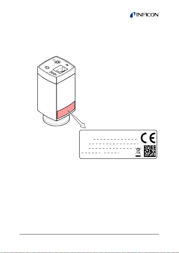
Product Identification
In all communications with INFICON, please specify the information given on the product nameplate. For convenient reference copy that information into the space provided below.
`
INFICON AG, LI-9496 Balzers
Model:
PN:
SN:
V W; LPS
2
tina83e1-a (2014-02)
Page 3

Validity
This document applies to products of the MAG50x and MPG50x
series:
3Mxx-xxx-0x0x
Measurement
Receptacle
Collector current
Ionization chamber
Measurement system
The part number (PN) can be taken from the product nameplate.
If not indicated otherwise in the legends, the illustrations in this
document correspond to the product with FCC receptacle and
vacuum connection DN 25 ISO-KF. They apply to the other
products by analogy.
We reserve the right to make technical changes without prior
notice.
N 1.5 ... 8.5 V
range
P 1.398 ... 8.598 V
Q 0.667 ... 10 V
0 FCC, 8-pin
0 D-Sub, 9-pin
Flange
6 DN 25 ISO-KF
7 DN 40 ISO-KF
8 DN 40 CF-R
Q DN 40 CF-F
0 High current
1 Low current
0 Stainless steel
0 Standard
3 Ceramic coated
Type
A
B
Inverted Magnetron
Inverted Magnetron Pirani
tina83e1-a (2014-02) 3
Page 4

Intended Use
Gemini MAG500, MAG504
The Cold Cathode Gauges Gemini MAG500 and MAG504 have
been designed for vacuum measurement of gases in the
pressure range of 1×10
-9
… 1×10⁻² mbar.
The gauges with PN 3MAx-xxx-0x0Q can be operated in
connection with an INFICON Vacuum Gauge Controller of the
VGC40x series.
Gemini MPG500, MPG504
The Cold Cathode Gauges Gemini MPG500 and MPG504 have
been designed for vacuum measurement of gases in the
pressure range of 1×10
-9
… 1000 mbar.
They must not be used for measuring flammable or combustible
gases in mixtures containing oxidants (e.g. atmospheric oxygen)
within the explosion range.
The gauges can be operated in connection with an INFICON
Vacuum Gauge Controller of the VGC40x series.
Functional Principle
Gemini MAG500, MAG504
The gauge functions with a cold cathode ionization measurement circuit (according to the inverted magnetron principle).
Over the whole measurement range, the measuring signal is
output as a logarithm of the pressure.
Gemini MPG500, MPG504
The gauge consists of two separate measuring systems (the
Pirani and the cold cathode system according to the inverted
magnetron principle). They are combined in such a way that for
the user, they behave like one measuring system.
4
tina83e1-a (2014-02)
Page 5

Over the whole measurement range, the measuring signal is
output as a logarithm of the pressure.
Scope of Delivery
1× gauge
1× pin for adjusting settings via buttons
1× Operating Manual German
1× Operating Manual English
tina83e1-a (2014-02) 5
Page 6

Contents
Product Identification 2
Validity 3
Intended Use 4
Functional Principle 4
Scope of Delivery 5
1
Safety 8
1.1 Symbols Used 8
1.2 Personnel Qualifications 8
1.3 General Safety Instructions 9
1.4 Liability and Warranty 9
2 Technical Data 10
2.1 Measuring Signal vs. Pressure 15
2.2 Gas Type Dependence MAG50x 18
2.3 Gas Type Dependence MPG50x 20
3 Installation 23
3.1 Vacuum Connection 23
3.2 Power Connection 27
3.2.1 FCC 68, 8-pin Connector 28
3.2.2 D-Sub, 9-pin Connector 29
4 Operation 30
4.1 Status Indication MAG 30
4.2 Status Indication MPG 31
4.3 Put MAG50x Into Operation 32
4.4 Put MPG50x Into Operation 32
4.5 Gas Type Dependence 33
4.6 Ignition Delay 33
4.7 Contamination 34
5 Deinstallation 36
6 Maintenance, Repair 38
6.1 Adjusting the Gauge 38
6.2 Cleaning the Gauge / Replacing Parts 40
6.2.1 Troubleshooting (measuring chamber) 41
6.2.2 Replacing Ionization Chamber and Ignition Aid 43
6.2.3 Replacing Measuring Chamber 45
6
tina83e1-a (2014-02)
Page 7

6.3 Troubleshooting 48
7 Returning the Product 51
8 Disposal 52
9 Options 53
10 Accessories 53
11 Spare Parts 53
11.1 Ignition aid for MAG50x and MPG50x 53
11.2 Ionization Chamber for MAG50x and MPG50x 54
11.3 Measuring Chamber Cpl. (Spare Sensor) 54
11.3.1 Measuring Chamber Cpl. for MAG500 54
11.3.2 Measuring Chamber Cpl. for MAG504 55
11.3.3 Measuring Chamber Cpl. for MPG500 55
11.3.4 Measuring Chamber Cpl. for MPG504 55
EC Declaration of Conformity 56
For cross-references within this document, the symbol (→ XY)
is used.
tina83e1-a (2014-02) 7
Page 8
1 Safety
1.1 Symbols Used
DANGER
Information on preventing any kind of physical injury.
WARNING
Information on preventing extensive equipment and environmental damage.
Caution
Information on correct handling or use. Disregard can lead to
malfunctions or minor equipment damage.
Notice
<…> Labeling
1.2 Personnel Qualifications
Skilled personnel
All work described in this document may only be carried out by
persons who have suitable technical training and the necessary experience or who have been instructed by the end-user
of the product.
8
tina83e1-a (2014-02)
Page 9

1.3 General Safety Instructions
• Adhere to the applicable regulations and take the necessary
precautions for the process media used.
Consider possible reactions with the product materials.
Consider possible reactions (e.g. explosion) of the process
media due to the heat generated by the product (MPG50x
only).
• Adhere to the applicable regulations and take the necessary
precautions for all work you are going to do and consider the
safety instructions in this document.
• Before beginning to work, find out whether any vacuum components are contaminated. Adhere to the relevant regulations
and take the necessary precautions when handling contaminated parts.
Communicate the safety instructions to all other users.
1.4 Liability and Warranty
INFICON assumes no liability and the warranty becomes null
and void if the end-user or third parties
• disregard the information in this document
• use the product in a non-conforming manner
• make any kind of interventions (modifications, alterations etc.)
on the product
• use the product with accessories not listed in the product
documentation.
The end-user assumes the responsibility in conjunction with the
process media used.
Gauge failures due to contamination or wear and tear, as well as
expendable parts (e.g. ionization chamber, ignition aid, Pirani
filament (MPG50x)), are not covered by the warranty.
tina83e1-a (2014-02) 9
Page 10

2 Technical Data
Measurement range (air, N2)
MAG
MPG
Accuracy MAG (N
-8
… 1×10⁻² mbar 30% of reading
1×10
Accuracy MPG (N
-8
… 100 mbar
1×10
)
2
)
2
100 … 1000 mbar
Repeatability (N
MAG, 1×10
MPG, 1×10
)
2
-8
… 1×10⁻² mbar
-8
… 100 mbar
Gas type dependence
MAG
MPG
Voltage range (analog output) 0 … +10.5 V
Measurement range
3MAx-xxx-0x0N
3MAx-xxx-0x0Q
3MBx-xxx-0x0P
Voltage vs. pressure
3MAx-xxx-0x0N
3MAx-xxx-0x0Q
3MBx-xxx-0x0P
Status signal 14.5 … 30 V (ignited)
Error signal
3MAx-xxx-0x0N
3MAx-xxx-0x0Q
3MBx-xxx-0x0P
Output impedance
Load impedance
Step response time
-6
p > 10
mbar
-8
mbar
p = 10
1×10
1×10
30% of reading
50% of reading
5% of reading
5% of reading
→ 18
→ 20
+1.5 … +8.5 V (dc)
+0.667 … +10 V (dc)
+1.398 … +8.6 V (dc)
1 V/decade, logarithmic
1.33 V/decade, logarithmic
0.6 V/decade, logarithmic
<+0.5 V
≤+0.3 V
+9.5 … +10.5 V
2 × 4.7 Ω, short-circuit proof
≥10 kΩ, short-circuit proof
pressure dependent
<100 ms
≈1 s
-9
… 1×10⁻² mbar
-9
… 1000 mbar
10
tina83e1-a (2014-02)
Page 11
Gauge identification
3MAx-xxx-0x0N
3MAx-xxx-0x0Q
3MBx-xxx-0x0P
–
100 kΩ referenced to supply
common
85 kΩ referenced to supply
common
Status signal (digital output)
Current rating 100 mA
High voltage is ON +14.5 … +30 V (dc)
(depending on supply voltage)
High voltage is OFF 0 V (dc)
High voltage cut-in, low active, Pin 7 (digital input)
High voltage ON
High voltage OFF
<2.5 V (dc)
>4.0 V (dc)
High voltage cut-in, high active, Pin 8 (digital input)
High voltage ON
High voltage OFF
Supply
>11.0 V (dc)
< 5.0 V (dc)
DANGER
The gauge may only be connected to power supplies, instruments, or control devices that conform
to the requirements of a grounded protective extralow voltage (SELV) and limited power source
(LPS), Class 2. The connection to the gauge has to
be fused.
Supply voltage
at the gauge
Ripple ≤1 V
1)
2)
+14.5 … +30 V (dc)
pp
Power consumption ≤2 W
1)
INFICON controllers fulfill this requirement.
2)
The minimum voltage of the power supply unit must be increased
proportionally to the length of the sensor cable.
tina83e1-a (2014-02) 11
Page 12

Fuse to be connected 1) ≤1 AT
High voltage in the measuring chamber
Ignition voltage
Operating voltage
≤4.5 kV
≤3.3 kV
Current in the measuring chamber
High current
Low current
Electrical connection
3Mxx-xxx-000x
3Mxx-xxx-010x
Sensor cable
FCC connector
D-Sub connector
Cable length (FCC only) ≤50 m
Grounding concept
Vacuum connection – signal
common
Supply common – signal
common
≤500 µA
≤100 µA
FCC 68, 8-pin
D-Sub, 9-pin
8-pin, shielded
9-pin, shielded
→ "Power Connection"
connected via 10 kΩ
(potential difference ≤16 V)
conducted separately;
differential measurement is
recommended
(0.14 mm2/conductor)
12
tina83e1-a (2014-02)
Page 13

Materials exposed to vacuum
Vacuum connection
Measuring chamber
Pirani filament (
Feedthrough,
MPG50x) W
MAG/MPG500
Isolation
Ring
Anode, Pin
Feedthrough,
MAG/MPG504 ceramic coated
Ionization chamber
3MAx-0xx-0x0x
stainless steel (1.4435)
stainless steel (1.4435)
glass, ceramic (Al
stainless steel (1.4435)
2O3
)
Ni alloy
stainless steel
(1.4301, 1.4016)
Ignition aid stainless steel (1.4310)
Internal volume
DN 25 ISO-KF
DN 40 ISO-KF
DN 40 CF-F
DN 40 CF-R
Permissible pressure
(absolute)
Bursting pressure (absolute) >13 bar
3
≈19.9 cm
≈20.9 cm
≈25.2 cm
≈25.6 cm
3
3
3
10 bar, limited to inert gases
<55°C
Permissible temperatures
Operation
Pirani filament (MPG)
Bakeout
Storage
Relative humidity for 30 days a
year
-8
1×10
… 1×10⁻² mbar
-7
… 1×10⁻² mbar
1×10
+5 °C … +55 °C
120 °C
3)
≤150 °C
–40 °C … +70 °C
≤70% (non-condensing)
≤95% (non-condensing)
Mounting orientation any
Use indoors only, altitude up to
6000 m NN
Degree of protection IP 40
3)
Without electronics unit.
tina83e1-a (2014-02) 13
Page 14
Weight
DN 25 ISO-KF
DN 40 ISO-KF
DN 40 CF-F und CF-R
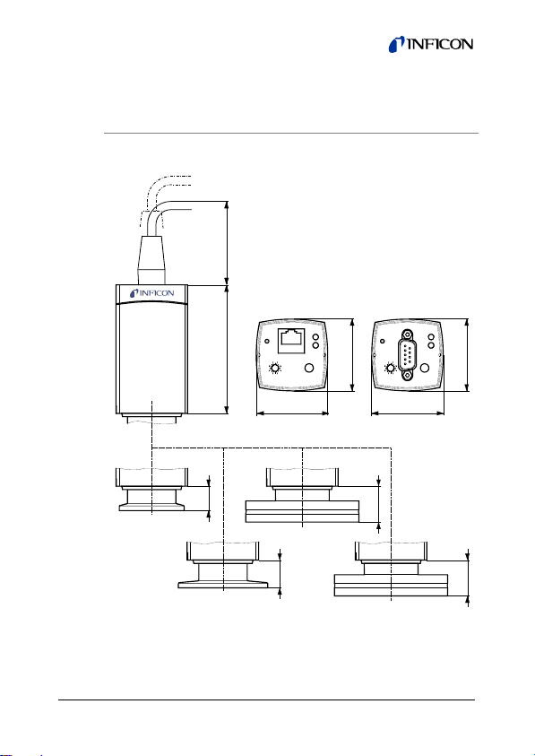
Dimensions [mm]
15
DN 25 ISO-KF
DN 40 ISO-KF
79 60
FCC 68
8-pin
ST
ADJ
HV-ST
0
2
E
4
C
6
A
DIA
8
CAL
44
DN 40 CF-R
17
<280 g
<320 g
<570 g
D-Sub
9-pin
ADJ
44
0
2
E
4
C
6
A
8
CAL
23
DN 40 CF-F
ST
HV-ST
44
DIA
44
23
14
tina83e1-a (2014-02)
Page 15
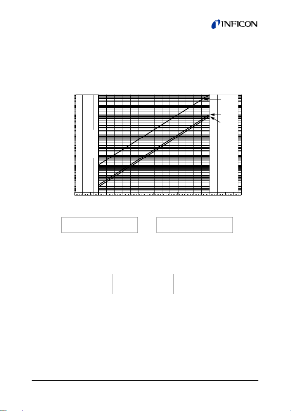
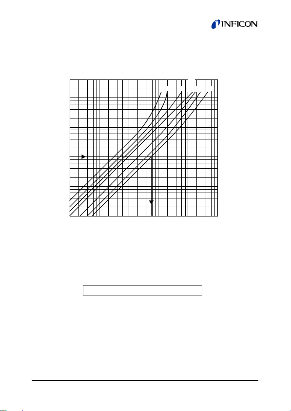
2.1 Measuring Signal vs. Pressure
Measurement range 1.5 … 8.5 V (3MAx-xxx-0x0N)
Pressure p
1E+00
1E–01
1E–02
1E–03
1E–04
1E–05
1E–06
1E–07
1E–08
1E–09
1E–10
valid in the range 1×10
where p pressure
underrange
sensor error
0.0 0.5 1.0 1.5 2.5 3.5 4.5 5.5 6.5 7.5 8.5 9.52.0 3.0 4.0 5.0 6.0 7.0 8.0 9.0 10.0
Measurement signal U [V]
p = 10
(U-c)
⇔
7.5×10
1×10
-9
-7
U = c + log10 p
mbar < p < 1×10⁻² mbar
-10
Torr < p < 7.5 ×10⁻³ Torr
Pa < p < 1 Pa
mbar Pa Torr
c 10.5 8.5 10.625
U measurement signal
c constant (pressure unit dependent)
Pa
mbar
torr
overrange
tina83e1-a (2014-02) 15
Page 16
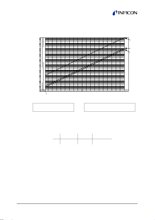
Measurement range 0.667 … 10 V (3MAx-xxx-0x0Q)
Pressure p
1E+00
1E–01
1E–02
1E–03
1E–04
underrange
1E–05
1E–06
1E–07
1E–08
sensor error
1E–09
1E–10
0.0 0.5 1.0 1.5 2.5 3.5 4.5 5.5 6.5 7.5 8.5 9.5 10.52.0 3.0 4.0 5.0 6.0 7.0 8.0 9.0 10.0
0.667
p = 10
valid in the range 1×10
Measurement signal U [V]
0.75(U-c)
⇔
-9
mbar < p < 1×10⁻² mbar
-10
Torr < p < 7.5 ×10⁻³ Torr
7.5×10
-7
1×10
Pa < p < 1 Pa
U = c + 1.33 log p
mbar Pa Torr
c 12.66 10 12.826
where p pressure
U measurement signal
c constant (pressure unit dependent)
Pa
mbar
torr
overrange
16
tina83e1-a (2014-02)
Page 17
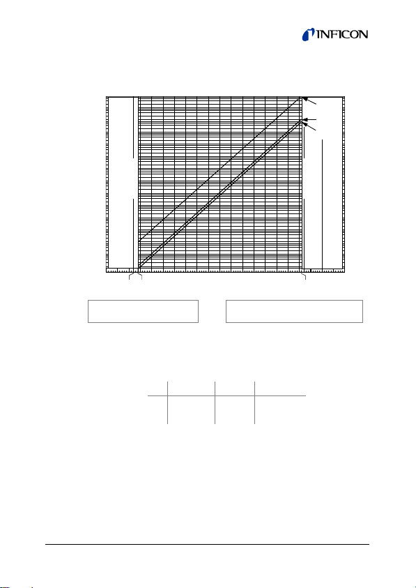
Measurement range 1.398 … 8.6 V (3MBx-xxx-0x0P)
Pressure p
1E+04
1E+02
1E+00
Pa
mbar
torr
1E–02
1E–04
1E–06
1E–08
1E–09
underrange
0.0 0.5 2.5 3.5 4.5 5.5
1.217
1.397
Measurement signal U [V]
1.667U-d
p = 10
valid in the range 1×10
7.5×10
1×10
6.5
⇔
-9
mbar < p < 1000 mbar
-10
-7
Pa < p < 1×10⁵ Pa
U = c + 0.6 log p
Torr < p < 750 Torr
overrange
sensor error
7.5 8.5 9.5 10.5
8.6
mbar Pa Torr
c 6.798 5.598 6.873
d 11.33 9.333 11.46
where p pressure
U measurement signal
c, d constant (pressure unit dependent)
tina83e1-a (2014-02) 17
Page 18
2.2 Gas Type Dependence MAG50x
Indicated pressure (gauge calibrated for air)
p [mbar]
4
2
–3
10
8
6
4
2
–4
10
8
6
4
2
–5
10
8
6
4
2
–6
10
8
6
4
2
–7
10
–7
10
246
10
–6
246
10
p
–5
246
[mbar]
eff
Xe Kr
10
Indication range below 10-5 mbar
In the range below 10-5 the pressure indication is linear. For
gases other than air, the pressure can be determined by means
of a simple conversion formula:
= K × indicated pressure
p
eff
–4
246
CO
Ar
10
Air
O
N2H2Ne He
–3
2
246
–2
10
18
tina83e1-a (2014-02)
Page 19

where: Gas type K
Air (N2, O2, CO) 1.0
Xe 0.4
Kr 0.5
Ar 0.8
H
2.4
2
Ne 4.1
He 5.9
These conversion factors are average values.
A mixture of gases and vapors is often involved. In this
case, accurate determination is only possible with a
partial pressure measurement instrument, e.g. a
quadrupole mass spectrometer.
tina83e1-a (2014-02) 19
Page 20

2.3 Gas Type Dependence MPG50x
Indication range from 102 … 10-2 mbar
(Pirani-only operation)
Indicated pressure (gauge calibrated for air)
p [mbar]
2
10
8
6
4
2
1
10
8
6
4
2
0
10
8
6
4
2
–1
10
8
6
4
2
–2
10
10
Indication range
above 10-2 mbar
Water vapor
–3
–2
10
246
8 2 468 2 468 2 468 2 468
–1
10
10
0
H2He Ne
10
Air
N
2
O
2
CO
CO
2
Ar
Freon 12
Kr
Xe
1
p
[mbar]
eff
2
10
20
tina83e1-a (2014-02)
Page 21

Indication range 10-6 … 0.1 mbar
Indicated pressure (gauge calibrated for air)
p (mbar)
–1
10
8
6
4
2
–2
10
8
6
4
2
–3
10
8
6
4
2
–4
10
8
6
4
2
–5
10
8
6
4
2
–6
10
–6
10
24
Indication range
10-6 ... 10-1 mbar
Ar
Air
N
2
O
2
CO
He
–5
10
6
8
–4
10
246824624624
–3
10
8
–2
10
8
p
(mbar)
eff
–1
10
6
8
Indication range below 10-5 mbar
In the range below 10-5 the pressure indication is linear. For
gases other than air, the pressure can be determined by means
of a simple conversion formula:
= K × indicated pressure
p
eff
tina83e1-a (2014-02) 21
Page 22

where: Gas type K
Air (N2, O2, CO) 1.0
Xe 0.4
Kr 0.5
Ar 0.8
H
2.4
2
Ne 4.1
He 5.9
These conversion factors are average values.
A mixture of gases and vapors is often involved. In this
case, accurate determination is only possible with a
partial pressure measurement instrument, e.g. a
quadrupole mass spectrometer.
22
tina83e1-a (2014-02)
Page 23

3 Installation
3.1 Vacuum Connection
DANGER
DANGER: overpressure in the vacuum system
>1 bar
Injury caused by released parts and harm caused
by escaping process gases can result if clamps are
opened while the vacuum system is pressurized.
Do not open any clamps while the vacuum system
is pressurized. Use the type clamps which are
suited to overpressure.
DANGER
DANGER: overpressure in the vacuum system
>2.5 bar
KF flange connections with elastomer seals (e.g.
O-rings) cannot withstand such pressures. Process
media can thus leak and possibly damage your
health.
Use O-rings provided with an outer centering ring.
tina83e1-a (2014-02) 23
Page 24

DANGER
DANGER: protective ground
Products that are not correctly connected to ground
can be extremely hazardous in the event of a fault.
Electrically connect the gauge to the grounded
vacuum chamber. This connection must conform to
the requirements of a protective connection according to EN 61010:
• CF connections fulfill this requirement
• For gauges with a KF flange, use a conductive
metallic clamping ring.
Caution
Caution: vacuum component
Dirt and damages impair the function of the vac-
uum component.
When handling vacuum components, take appro-
priate measures to ensure cleanliness and prevent
damages.
Caution
Caution: dirt sensitive area
Touching the product or parts thereof with bare
hands increases the desorption rate.
Always wear clean, lint-free gloves and use clean
tools when working in this area.
The gauge may be mounted in any orientation. To keep condensates and particles from getting into the measuring chamber
preferably choose a horizontal to upright position.
24
tina83e1-a (2014-02)
Page 25

For potentially contaminating applications and to protect the
measurement system against contamination, installation of the
optional seal with centering ring and filter is recommended
(Options → 53).
Remove the protective lid and connect the product to the
vacuum system.
Seal with centering ring
or
Protective lid
Seal with centering
Clamp
ring and filter
Keep the protective lid.
tina83e1-a (2014-02) 25
Page 26

When making a CF flange connection, it may be ad-
vantageous to temporarily remove the electronics unit.
Hexagon socket AF 2
26
Protective lid
Keep the protective lid.
WARNING: electric arcing
Helium may cause electric arcing with detrimental
effects on the electronics of the product.
Before performing any tightness tests put the pro-
duct out of operation and remove the electronics
unit.
WARNING
tina83e1-a (2014-02)
Page 27

3.2 Power Connection
Make sure the vacuum connection is properly made
(→ 23).
DANGER
The gauge may only be connected to power supplies, instruments or control devices that conform
to the requirements of a grounded protective extralow voltage (SELV) and limited power source
(LPS), Class 2. The connection to the gauge has to
be fused.
4)
Ground loops, differences of potential, or EMC problems
may affect the measurement signal. For optimum signal
quality, please do observe the following notes:
• Use an overall metal braided shielded cable. The
connector must have a metal case.
• Connect the supply common with protective ground
directly at the power.
• Use differential measurement input (signal common
and supply common conducted separately).
• Potential difference between supply common and
housing ≤16 V (overvoltage protection).
4)
INFICON controllers fulfill these requirements.
tina83e1-a (2014-02) 27
Page 28

3.2.1 FCC 68, 8-pin Connector
If no sensor cable is available, make one according to the
following diagram. Connect the sensor cable.
+
High active
Low active
–
Signal
4.7
4.7
Ident10 k
8
7
6
3
5
4
1
2
HV on
HV on
+
–
+
–
Electrical connection
Pin 1 Supply (14.5 … 30 V (dc))
Pin 2 Supply common GND
Pin 3 Signal output (measuring signal)
Pin 4 Gauge identification
Pin 5 Signal common
Pin 6 Status signal
*)
Pin 7
High voltage on/off (low active)
*)
High voltage on/off (high active)
Pin 8
*)
MAG only. Pin 7 and 8 are not assigned in
the MPG gauge.
28
1
8
FCC 68
8-pin
tina83e1-a (2014-02)
Page 29

3.2.2 D-Sub, 9-pin Connector
If no sensor cable is available, make one according to the
following diagram. Connect the sensor cable.
+
–
100nF
Signal
10 k
6 V
4.7
4.7
1Low active
9
3
7
4
2
HV on
+
–
+
–
Electrical connection
Pin 1 High voltage on/off (low active)
Pin 2 Supply common GND
Pin 3 Signal output (measuring signal)
Pin 4 Supply (14.5 … 30 V (dc))
Pin 5 not assigned
Pin 6 do not connect
Pin 7 Signal common
Pin 8 not assigned
Pin 9 Status signal
5
1
9
6
D-Sub
9-pin
female
soldering side
tina83e1-a (2014-02) 29
Page 30

4 Operation
4.1 Status Indication MAG
ADJ
E
C
Calibration
A
value
LED Meaning
<ST> <HV-ST>
off off No supply voltage
lit solid
green
lit solid
green
lit solid
green
blinking
red
off Supply voltage = ok,
blinking
green
lit solid
green
off EEPROM error
Troubleshooting (→ 49).
ST
HV-ST
0
2
4
6
DIA
8
CAL
no high voltage in the measuring
chamber
Supply voltage = ok,
pressure in the cold cathode range, cold
cathode has not ignited
Cold cathode has ignited
Supply voltage
Error
High voltage
cold cathode
For factory
setting only
30
tina83e1-a (2014-02)
Page 31

4.2 Status Indication MPG
ST
HV-ST
0
2
4
6
DIA
8
CAL
Calibration
ADJ
E
C
A
value
LED Meaning
<ST> <HV-ST>
off off No supply voltage
lit solid
green
lit solid
green
lit solid
green
off Supply voltage = ok, Pirani active, no
blinking
green
lit solid
green
high voltage in the measuring chamber
Supply voltage = ok,
pressure in the cold cathode range, cold
cathode has not ignited
Cold cathode has ignited.
lit solid red off Measurement system error
blinking
red
off EEPROM error
Troubleshooting (→ 50).
Supply voltage
Error
High voltage
cold cathode
For factory
setting only
tina83e1-a (2014-02) 31
Page 32

4.3 Put MAG50x Into Operation
Caution
Turn on the gauge/high voltage only at pressures
-2
<10
mbar to prevent excessive contamination.
If you are using an INFICON measurement unit for
Compact Gauges with at least two gauge connections, the cold cathode gauge can be controlled, for
example, by a Pirani gauge.
MAG50x with FCC connector
When the supply voltage is applied and the high voltage is
switched on via pin 7 (low active) or pin 8 (high active), the
measuring signal is available at the signal output.
MAG50x with D-Sub connector
When the supply voltage is applied and the high voltage is
switched on via pin 1 (low active), the measuring signal is available at the signal output.
4.4 Put MPG50x Into Operation
When the supply voltage is applied, the measuring signal is
available at the signal output (→ 28).
Allow for a stabilizing time of approx. 10 min. Once the gauge
has been switched on, it can remain in operation permanently
irrespective of the pressure.
Measurement Principle, Measuring Behavior
The gauge consists of two separate measuring systems (Pirani
and cold cathode system according to the inverted magnetron
principle). They are combined in such a way that for the user,
they behave like one measuring system.
32
tina83e1-a (2014-02)
Page 33

The optimum measuring configuration for the particular pressure
range, in which measurement is performed, is used:
10-3 mbar
Cold cathode Pirani
-2
1×10⁻⁹ mbar
mbar
10
• The Pirani measuring circuit is always on
• The cold cathode measuring circuit is controlled by the Pirani
circuit and is activated only at pressures p < 1×10
As long as the cold cathode measuring circuit has not ignited,
the measuring value of the Pirani is output as measuring signal.
4.5 Gas Type Dependence
The measurement value is gas dependent. The pressure reading
applies to dry air, O
corrected:
, CO and N2. For other gases, it has to be
2
• (MAG50x → 18)
• (MPG50x → 20).
If the gauge is operated with an INFICON controller, a calibration
factor for correction of the actual reading can be applied (→
the corresponding controller).
4.6 Ignition Delay
An ignition delay occurs when cold cathode gauges are switched
on. The delay time increases at low pressures and is typically:
1×10⁻⁵ … 1×10⁻² mbar < 1 second
-7
… 1×10⁻⁵ mbar <20 seconds
1×10
-9
… 1×10⁻⁷ mbar < 2 minutes
5×10
-9
<5×10
mbar <20 minutes
1000 mbar
-2
mbar
of
tina83e1-a (2014-02) 33
Page 34

MPG50x only
As long as the cold cathode measuring circuit has not ignited,
the measuring value of the Pirani is output as measuring signal.
The status output (= 0 V) indicates the Pirani-only operation.
If the high voltage is activated at a pressure p < 3×10⁻⁹,
the gauge cannot recognize whether the cold cathode
system has ignited.
Once flanged on, permanently leave the gauge in the
operating mode irrespective of the pressure range. Like
this, the ignition delay of the cold cathode measuring
circuit is always negligible (<1 s), and thermal stabilizing
effects are minimized.
4.7 Contamination
Gauge failures due to contamination or wear and tear, as well as
expendable parts (e.g. ionization chamber, ignition aid, Pirani
filament (MPG50x)), are not covered by the warranty.
Gauge contamination is influenced by the process media used
as well as any existing or new contaminants and their respective
partial pressures. Continuous operation in the range of
-4
10
mbar ... 10-2 mbar can cause severe contamination as well
as reduced up-time.
Contamination of the gauge generally causes a deviation of the
measured values:
• MPG50x only: In the high pressure range
-3
(1×10
mbar … 0.1 mbar), the pressure reading is too high
(contamination of the Pirani element). Readjustment of the
Pirani → 38.
• In the low pressure range (p < 1×10
dication is usually too low (as a consequence of the contamination of the cold cathode system). In case of severe contamination, instabilities can occur (layers of the measuring chamber peel off). Contamination due to isolating layers can even
lead to a complete failure of the discharge.
-3
mbar), the pressure in-
34
tina83e1-a (2014-02)
Page 35

Contamination can to a certain extent be reduced by:
• geometric protection (e.g. screenings, elbows) against particles that spread rectilinearly
• mounting the flange of the gauge at a place where the partial
pressure of the pollutants is particularly low.
Special precautions are required for vapors deposited under
plasma (of the cold cathode measuring system). While vapors
occur it may even be necessary
• to temporarily switch of the gauge
• to temporarily seal off of the gauge from the vacuum chamber
using a valve.
tina83e1-a (2014-02) 35
Page 36

5 Deinstallation
DANGER
DANGER: contaminated parts
Contaminated parts can be detrimental to health
and environment.
Before beginning to work, find out whether any
parts are contaminated. Adhere to the relevant
regulations and take the necessary precautions
when handling contaminated parts.
Caution
Caution: vacuum component
Dirt and damages impair the function of the vac-
uum component.
When handling vacuum components, take appro-
priate measures to ensure cleanliness and prevent
damages.
Caution
Caution: dirt sensitive area
Touching the product or parts thereof with bare
hands increases the desorption rate.
Always wear clean, lint-free gloves and use clean
tools when working in this area.
Vent the vacuum system.
Put the gauge out of operation and disconnect the sensor
cable.
36
tina83e1-a (2014-02)
Page 37

Remove gauge from the vacuum system and install the
protective lid.
When deinstalling the CF flange connection, it may
be advantageous to temporarily remove the electronics unit (→ 26).
Seal with centering ring
Protective lid
Clamp
tina83e1-a (2014-02) 37
Page 38

6 Maintenance, Repair
Gauge failures due to contamination and wear and tear,
as well as expendable parts (e.g. ionization chamber,
ignition aid, Pirani filament (MPG50x)), are not covered
by the warranty.
INFICON assumes no liability and the warranty becomes null
and void if any repair work is carried out by the end-user or third
parties.
6.1 Adjusting the Gauge
MAG50x
The gauge is factory-calibrated and requires no maintenance. In
the event of a defect
• only replace the ionization chamber and ignition aid, or
• replace the measuring chamber cpl. (spare sensor).
MPG50x
The cold cathode measuring circuit, which is dominant for low
pressures (<1×10
adjusted. The HV adjustment of the Pirani measuring circuit is
carried out automatically by the gauge itself at pressures
-5
<1×<10
15 minutes. Any adjustment has a negligible effect on the pressure range between approx. 10
If used under different climatic conditions, through extreme temperatures, aging or contamination the characteristic curve can be
offset and a manually readjustment or a maintenance may become necessary.
An adjustment via the <ADJ> button can become necessary
(procedure
output.
-3
mbar), is factory-calibrated and cannot be
mbar. The new zero point is saved non-volatile every
-2
mbar and 102 mbar.
→ , ), if pressure values <10
-2
mbar are no longer
38
tina83e1-a (2014-02)
Page 39

For adjusting the zero, operate the gauge under the same constant ambient conditions and in the same mounting orientation
as normally.
If you are using a seal with centering ring and filter, check
that they are clean or replace them if necessary
(→ "Deinstallation").
Put the gauge into operation and operate it at atmospheric
pressure for at least 10 minutes.
Press the <ADJ> button with a pin (max. ø1.1 mm) and the
ATM adjustment is carried out: The Pirani sensor is adjusted to 1000 mbar (duration ≈5 s).
ATM
HV
If the pressure value 1000 mbar is output at the
measurement value output, the adjustment has been
successful. Otherwise, repeat the adjustment procedure.
Evacuate the vacuum system to p < 10
least 2 minutes.
-5
mbar and wait at
tina83e1-a (2014-02) 39
Page 40

Press the <ADJ> button with a pin and the HV adjustment
is carried out (duration ≈5 s).
If the pressure value 1×10⁻⁵ mbar is output at the
measurement value output, the adjustment has been
successful. Otherwise, repeat the adjustment proce-
6.2 Cleaning the Gauge / Replacing Parts
dure.
In case of severe contamination or defective (e.g. pirani
filament rupture (MPG50x)), replace the complete
measuring chamber (Spare Parts → 53).
DANGER
DANGER: contaminated parts
Contaminated parts can be detrimental to health
and environment.
Before beginning to work, find out whether any
parts are contaminated. Adhere to the relevant regulations and take the necessary precautions when
handling contaminated parts.
40
Caution: vacuum component
Dirt and damages impair the function of the vac-
uum component.
When handling vacuum components, take appro-
priate measures to ensure cleanliness and prevent
damages.
Caution
tina83e1-a (2014-02)
Page 41

Caution
Caution: dirt sensitive area
Touching the product or parts thereof with bare
hands increases the desorption rate.
Always wear clean, lint-free gloves and use clean
tools when working in this area.
DANGER
DANGER: cleaning agents
Cleaning agents can be detrimental to health and
environment.
Adhere to the relevant regulations and take the
necessary precautions when handling and
disposing of cleaning agents. Consider possible
reactions with the product materials (→ 13).
Precondition
Gauge deinstalled.
6.2.1 Troubleshooting (measuring chamber)
If the cause of the fault is suspected to be in the measuring
chamber, the following checks can be made with an ohmmeter.
Tools / material required
• Allen wrench AF 2
• Pliers for retaining ring
• Ohmmeter
tina83e1-a (2014-02) 41
Page 42

5
4
3
2
1
Unfasten the hexagon socket set screw (4) and remove the
complete measuring chamber (3) from the electronics
unit (5).
Remove the retaining ring (1) as well as the ionization
chamber (2) from the measuring chamber (3).
Check the ionization chamber and the measuring chamber
for contamination:
• Ionization chamber is contaminated only: Replace
ionization chamber (
• Measuring chamber is severely contaminated: Replace
complete measuring chamber (
→ 43)
→ 45).
42
tina83e1-a (2014-02)
Page 43

Using an ohmmeter, make following measurements on the
contact pins.
Measurement
between pins
1 + 4
1 + 2
5 + measuring
chamber
2
>>40 Ω Pirani filament rupture
>>1078 Ω
at 20 °C
∞ <<∞ Contamination, short
4
≈1078 Ω
at 20 °C
3
≈40 Ω
1
5
All of theses faults can only be remedied by replacing the
complete measuring chamber (
Possible cause
(MPG50x only)
Pirani temperature
sensor rupture
(MPG50x only)
circuit cold cathode
Measuring chamber
→ 45).
We recommend to perform a leak test (leak rate
<1×10
-9
mbar l/s).
6.2.2 Replacing Ionization Chamber and Ignition Aid
Precondition
Troubleshooting (measuring chamber) performed (→ 41).
Due to contamination remove the ignition aid with the
removing tool (Accessories
tina83e1-a (2014-02) 43
→ 53).
Page 44

We recommend to rub the inside walls of the measuring
chamber up to the groove for the retaining ring to a bright
finish using a polishing cloth.
• The sealing surfaces must only be worked
concentrically.
• Do not bend the anode.
Insert the new ignition aid into the mounting tool and slide it
onto the anode (Spare Parts
→ 53).
Slide a new ionization chamber (2) into the measuring
chamber (3) until the mechanical stop is reached and
mount the retaining ring (1) (Spare Parts
Observe correct
orientation of the
ionization chamber
2
3
1
We recommend to perform a leak test (leak rate
44
<1×10
-9
mbar l/s).
→ 53).
tina83e1-a (2014-02)
Page 45

Carefully slide the measuring chamber cpl. (3) (clean or
new) into the electronics unit (5) until the mechanical stop
is reached.
Pins aligned straight.
3
5
4
Fasten the measuring chamber (3) by means of the
hexagon socket set screw (4).
6.2.3 Replacing Measuring Chamber
Precondition
Troubleshooting (measuring chamber) performed (→ 41).
tina83e1-a (2014-02) 45
Page 46

Set the calibration value of the spare sensor with the
<CAL> switch on the electronics unit (5).
0
E
2
C
4
A
6
8
ADJ
E
C
A
CAL
ST
HV-ST
0
2
4
6
8
5
DIA
Calibration value
spare sensor
(measuring chamber cpl.)
8
Carefully slide the measuring chamber cpl. (3) into the
electronics unit (5) until the mechanical stop is reached.
Pins aligned straight.
46
5
4
3
tina83e1-a (2014-02)
Page 47

Fasten the measuring chamber (3) by means of the
hexagon socket set screw (4).
MPG50x gauge only: Perform an ATM and HV adjustment
of the Pirani measuring circuit via the <ADJ> button
(→ 39).
A recalibration of the MAG50x gauge is not
necessary.
We recommend to perform a leak test (leak rate
tina83e1-a (2014-02) 47
-9
<1×10
mbar l/s) and a function test of the gauge on the
teak detector.
WARNING
WARNING: electric arcing
Helium may cause electric arcing with detrimental
effects on the electronics of the product.
Before performing any tightness tests put the pro-
duct out of operation and remove the electronics
unit.
Page 48

6.3 Troubleshooting
In case of an error, it may be helpful to just turn off the
mains supply and turn it on again after 5 s.
48
tina83e1-a (2014-02)
Page 49

Correction
Possible cause
signal
Status
mbar and
-2
mbar).
-9
Turn on power supply.
Replace ionization cham-
ber or measuring cham-
ber cpl.(→ 43, 45).
Switch on the high
voltage (→ 28).
Evacuate the vacuum
system to <10
switch the gauge off and
on again via "HV ON".
Wait, until the gas dis-
charge has ignited
(≈5 minutes at a pressure
of 10
Switch the gauge off and
on again after 5 s.
Replace the gauge.
Replace the measuring
chamber cpl. (→ 45).
No supply voltage.
Gauge contaminated.
No high voltage in the
measuring chamber.
Overpressure in the
measuring chamber.
Gas discharge has not
ignited.
EEPROM error.
0
0
0
0
0
Measuring chamber
14.5 …
severely contaminated.
30 V
LED
<HV-ST>
LED
<ST>
Problem
off
off
No voltage at signal output.
off
green
lid solid
green
lid solid
Measuring signal unstable.
green
lid solid
Voltage at signal output
1.2 V (3MAx-xxx-0x0N)
0.4 V (3MAx-xxx-0x0Q).
blinking
lid solid
green
green
off
blinking
Voltage at signal output con-
red
tinually
lid solid
lid solid
< 0.3 V (3MAx-xxx-0x0N)
< 0.5 V (3MAx-xxx-0x0Q).
Signal continually at approx.
tina83e1-a (2014-02) 49
-4
green
green
mbar.
5×10
Page 50

Correction
Possible cause
Status
signal
mbar).
-9
Turn on power supply.
Replace ionization cham-
ber or measuring cham-
ber cpl (→ 43, 45).
Wait, until the gas dis-
charge has ignited
(≈5 minutes at a pressure
of 10
Perform a HV adjustment
via button (→ 39).
Replace the measuring
chamber cpl. (→ 45).
Switch the gauge off and
on again after 5 s.
Replace the gauge.
Replace the measuring
chamber cpl. (→ 45).
No supply voltage.
Gauge contaminated.
Gas discharge has not
ignited.
Pirani zero point shift.
Pirani defective.
EEPROM error.
0
0
0
0
0
0
Measuring chamber
14.5 …
severely contaminated.
30 V
50
LED
LED
Problem
off
<HV-ST>
off
<ST>
No voltage at signal output.
off
off
green
green
blinking
lid solid
Voltage at signal output does
green
green
not drop under <4.82 V.
lid solid
Voltage at signal output con-
green
tinually > 5.6 V.
lid solid
lid solid
Measuring signal unstable.
off
red
red
lid solid
blinking
Voltage at signal output con-
tinually > 9.5 V.
tina83e1-a (2014-02)
lid solid
lid solid
Signal continually at approx.
-4
green
green
mbar.
5×10
Page 51

7 Returning the Product
WARNING
WARNING: forwarding contaminated products
Contaminated products (e.g. radioactive, toxic,
caustic or microbiological hazard) can be detrimental to health and environment.
Products returned to INFICON should preferably be
free of harmful substances. Adhere to the forwarding regulations of all involved countries and forwarding companies and enclose a duly completed
*)
Form under www.inficon.com
declaration of contamination
Products that are not clearly declared as "free of harmful substances" are decontaminated at the expense of the customer.
Products not accompanied by a duly completed declaration of
contamination are returned to the sender at his own expense.
*)
.
tina83e1-a (2014-02) 51
Page 52

8 Disposal
DANGER
DANGER: contaminated parts
Contaminated parts can be detrimental to health
and environment.
Before beginning to work, find out whether any
parts are contaminated. Adhere to the relevant regulations and take the necessary precautions when
Separating the components
After disassembling the product, separate its components according to the following criteria:
• Contaminated components
• Other components
handling contaminated parts.
WARNING
WARNING: substances detrimental to the environment
Products or parts thereof (mechanical and electric
components, operating fluids etc.) can be detrimental to the environment.
Dispose of such substances in accordance with the
relevant local regulations.
Contaminated components (radioactive, toxic, caustic or biological hazard etc.) must be decontaminated in accordance
with the relevant national regulations, separated according to
their materials, and disposed of.
Such components must be separated according to their materials and recycled.
52
tina83e1-a (2014-02)
Page 53

9 Options
Seal with centering ring and fine filter,
DN 25 ISO-KF (stainless steel)
10 Accessories
Mounting / removing tool for ignition aid 351-550
11 Spare Parts
When ordering spare parts, always indicate:
• all information on the product nameplate
• description and ordering number
11.1 Ignition aid for MAG50x and MPG50x
ignition aid (set of 10 pieces) 351-551
Ordering No.
211-098
Ordering No.
Ordering No.
tina83e1-a (2014-02) 53
Page 54

11.2 Ionization Chamber for MAG50x and MPG50x
Ionization chamber (stainless steel) 351-555
11.3 Measuring Chamber Cpl. (Spare Sensor)
Measuring chamber
Ionization chamber
Retaining ring
Ordering No.
11.3.1 Measuring Chamber Cpl. for MAG500
Ionization chamber made of stainless steel Ordering No.
DN 25 ISO-KF
DN 40 ISO-KF
DN 40 CF-R
DN 40 CF-F
54
3MA0-0x6-xxxx
3MA0-0x7-xxxx
3MA0-0x8-xxxx
MAG500
3MA0-0xQ-xxxx
351-500
351-512
351-536
351-524
tina83e1-a (2014-02)
Page 55

11.3.2 Measuring Chamber Cpl. for MAG504
Ionization chamber made of stainless steel,
coated
Al
2O3
3MA3-0x6-xxxx
3MA3-0x7-xxxx
3MA3-0x8-xxxx
MAG504
3MA3-0xQ-xxxx
DN 25 ISO-KF
DN 40 ISO-KF
DN 40 CF-R
DN 40 CF-F
11.3.3 Measuring Chamber Cpl. for MPG500
Ionization chamber made of stainless steel Ordering No.
3MB0-0x6-xxxx
3MB0-0x7-xxxx
3MB0-0x8-xxxx
MPG500
3MB0-0xQ-xxxx
DN 25 ISO-KF
DN 40 ISO-KF
DN 40 CF-R
DN 40 CF-F
11.3.4 Measuring Chamber Cpl. for MPG504
Ionization chamber made of stainless steel,
coated
Al
2O3
3MB3-0x6-xxxx
3MB3-0x7-xxxx
3MB3-0x8-xxxx
MPG504
3MB3-0xQ-xxxx
DN 25 ISO-KF
DN 40 ISO-KF
DN 40 CF-R
DN 40 CF-F
Ordering No.
351-501
351-513
351-537
351-525
351-506
351-518
351-536
351-542
Ordering No.
351-507
351-519
351-543
351-531
tina83e1-a (2014-02) 55
Page 56

EC Declaration of Conformity
We, INFICON, hereby declare that the equipment mentioned
below complies with the provisions of the Directive relating to
electromagnetic compatibility 2004/108/EC and the Directive on
the restriction of the use of certain hazardous substances in
electrical and electronic equipment 2011/65/EU.
Cold Cathode & Cold Cathode Pirani Gauge
Gemini MAG500, MAG504
Gemini MPG500, MPG504
Standards
Harmonized and international / national standards and specifications:
• EN 61000-6-2:2005
• EN 61000-6-3:2007
• EN 61326-1:2006
measurement, control and laboratory use)
Manufacturer / Signatures
INFICON AG, Alte Landstraße 6, LI-9496 Balzers
29 November 2013 29 November 2013
(EMC: generic immunity standard)
(EMC: generic emission standard)
(EMC requirements for electrical equipment for
56
Dr. Urs Wälchli
Managing Director
Markus Truniger
Product Manager
tina83e1-a (2014-02)
Page 57

Notes
tina83e1-a (2014-02) 57
Page 58

Notes
58
tina83e1-a (2014-02)
Page 59

Notes
tina83e1-a (2014-02) 59
Page 60

LI–9496 Balzers
Liechtenstein
Tel +423 / 388 3111
Fax +423 / 388 3700
Original: German tina83d1-a (2014-02) reachus@inficon.com
t i na83e1- a
www.inficon.com
 Loading...