

Page 1
C
over Page
OPERATING MANUAL
Front Load Single and Dual
Sensors
PN 074-156N
Page 2

Page 3

Title P
age
www.inficon.com reachus@inficon.com
©2014 INFICON
®
OPERATING MANUAL
Front Load Single and Dual
Sensors
PN 074-156N
Page 4

Trademarks
The trademarks of the products mentioned in this manual are held by the companies that
produce them.
RateWatcher™ is a registered trademark of INFICON GmbH.
Teflon® and Viton® are registered trademarks of E. I. duPont de Nemours Company or its affiliates.
Swagelok® is a registered trademark of Swagelok Company.
VCR®, VCO®, and Ultra-Torr® are registered trademarks of Cajon Company.
ConFlat® is a registered trademark of Varian Corporation.
FOMBLIN® is a registered trademark of Ausimont SpA.
Microdot® is a registered trademark of Microdot Corp.
Scotch-Brite™ is a trademark of 3M.
All other brand and product names are trademarks or registered trademarks of their respective companies.
Disclaimer
The information contained in this manual is believed to be accurate and reliable. However, INFICON assumes
no responsibility for its use and shall not be liable for any special, incidental, or consequential damages related
to the use of this product.
Due to our continuing program of product improvements, specifications are subject to change without notice.
Copyright
©2014 All rights reserved.
Reproduction or adaptation of any part of this document without permission is unlawful.
Page 5

Warranty
WARRANTY AND LIABILITY - LIMITATION: Seller warrants the products
manufactured by it, or by an affiliated company and sold by it, and described on
the reverse hereof, to be, for the period of warranty coverage specified below, free
from defects of materials or workmanship under normal proper use and service.
The period of warranty coverage is specified for the respective products in the
respective Seller instruction manuals for those products but shall not be less than
one (1) year from the date of shipment thereof by Seller. Seller's liability under this
warranty is limited to such of the above products or parts thereof as are returned,
transportation prepaid, to Seller's plant, not later than thirty (30) days after the
expiration of the period of warranty coverage in respect thereof and are found by
Seller's examination to have failed to function properly because of defective
workmanship or materials and not because of improper installation or misuse and
is limited to, at Seller's election, either (a) repairing and returning the product or
part thereof, or (b) furnishing a replacement product or part thereof, transportation
prepaid by Seller in either case. In the event Buyer discovers or learns that a
product does not conform to warranty, Buyer shall immediately notify Seller in
writing of such non-conformity, specifying in reasonable detail the nature of such
non-conformity. If Seller is not provided with such written notification, Seller shall
not be liable for any further damages which could have been avoided if Seller had
been provided with immediate written notification.
THIS WARRANTY IS MADE AND ACCEPTED IN LIEU OF ALL OTHER
WARRANTIES, EXPRESS OR IMPLIED, WHETHER OF MERCHANTABILITY OR
OF FITNESS FOR A PARTICULAR PURPOSE OR OTHERWISE, AS BUYER'S
EXCLUSIVE REMEDY FOR ANY DEFECTS IN THE PRODUCTS TO BE SOLD
HEREUNDER. All other obligations and liabilities of Seller, whether in contract or
tort (including negligence) or otherwise, are expressly EXCLUDED. In no event
shall Seller be liable for any costs, expenses or damages, whether direct or
indirect, special, incidental, consequential, or other, on any claim of any defective
product, in excess of the price paid by Buyer for the product plus return
transportation charges prepaid.
No warranty is made by Seller of any Seller product which has been installed,
used or operated contrary to Seller's written instruction manual or which has been
subjected to misuse, negligence or accident or has been repaired or altered by
anyone other than Seller or which has been used in a manner or for a purpose for
which the Seller product was not designed nor against any defects due to plans or
instructions supplied to Seller by or for Buyer.
This manual is intended for private use by INFICON® Inc. and its customers.
Contact INFICON before reproducing its contents.
NOTE: These instructions do not provide for every contingency that may arise in
connection with the installation, operation or maintenance of this equipment.
Should you require further assistance, please contact INFICON.
www.inficon.com reachus@inficon.com
Page 6

Page 7

Front Load Single and Dual Sensors Operating Manual
Table Of Contents
Cover Page
Title Page
Trademarks
Disclaimer
Copyright
Warranty
Chapter 1
Introduction
1.1 Introduction. . . . . . . . . . . . . . . . . . . . . . . . . . . . . . . . . . . . . . . . . . . . . . . . . . 1-1
1.2 Definition of Notes, Cautions and Warnings. . . . . . . . . . . . . . . . . . . . . . . . .1-2
1.3 How to Contact INFICON . . . . . . . . . . . . . . . . . . . . . . . . . . . . . . . . . . . . . . .1-2
1.3.1 Returning Sensor to INFICON . . . . . . . . . . . . . . . . . . . . . . . . . . . . . . . . . . .1-3
1.4 Unpacking and Inspection . . . . . . . . . . . . . . . . . . . . . . . . . . . . . . . . . . . . . .1-3
1.4.1 Single Sensor Configuration Overview and Parts . . . . . . . . . . . . . . . . . . . . 1-4
1.4.2 Dual Sensor Configuration Overview and Parts. . . . . . . . . . . . . . . . . . . . . . 1-5
1.5 Front Load Single Sensors (PN SL-XXXXX) . . . . . . . . . . . . . . . . . . . . . . . .1-6
1.5.1 Specifications . . . . . . . . . . . . . . . . . . . . . . . . . . . . . . . . . . . . . . . . . . . . . . . . 1-7
1.5.2 Materials . . . . . . . . . . . . . . . . . . . . . . . . . . . . . . . . . . . . . . . . . . . . . . . . . . . . 1-8
1.5.3 Installation Requirements . . . . . . . . . . . . . . . . . . . . . . . . . . . . . . . . . . . . . . . 1-8
1.5.4 Single Sensor Drawings . . . . . . . . . . . . . . . . . . . . . . . . . . . . . . . . . . . . . . . .1-9
1.6 Front Load Dual Sensor (PN DL-AXXX). . . . . . . . . . . . . . . . . . . . . . . . . . . 1-14
1.6.1 Specifications . . . . . . . . . . . . . . . . . . . . . . . . . . . . . . . . . . . . . . . . . . . . . . . 1-14
1.6.2 Materials . . . . . . . . . . . . . . . . . . . . . . . . . . . . . . . . . . . . . . . . . . . . . . . . . . . 1-15
1.6.3 Installation Requirements . . . . . . . . . . . . . . . . . . . . . . . . . . . . . . . . . . . . . . 1-15
PN 074-156N
1.6.4 Dual Sensor Drawings . . . . . . . . . . . . . . . . . . . . . . . . . . . . . . . . . . . . . . . .1-16
1.7 Shutter Module (PN 750-210-G1 and 750-210-G3) . . . . . . . . . . . . . . . . . . 1-19
1.7.1 Specifications . . . . . . . . . . . . . . . . . . . . . . . . . . . . . . . . . . . . . . . . . . . . . . . 1-19
1.7.2 Shutter Module Drawings . . . . . . . . . . . . . . . . . . . . . . . . . . . . . . . . . . . . . .1-20
1.8 Feedthroughs . . . . . . . . . . . . . . . . . . . . . . . . . . . . . . . . . . . . . . . . . . . . . . . 1-23
1.8.1 Specifications for 2.54 cm (1 in.) Bolt . . . . . . . . . . . . . . . . . . . . . . . . . . . . . 1-23
1.8.2 Specifications for CF40 (2-3/4 in. ConFlat) . . . . . . . . . . . . . . . . . . . . . . . .1-24
1.8.3 Feedthrough Drawings . . . . . . . . . . . . . . . . . . . . . . . . . . . . . . . . . . . . . . . .1-25
TOC - 1
Page 8

Chapter 2
2.1 Pre-installation Sensor Check . . . . . . . . . . . . . . . . . . . . . . . . . . . . . . . . . . . 2-1
2.1.1 Sensor Check with XTC/3, IC6, or Cygnus 2
2.1.2 Sensor Check with STM-2XM, STM-3, SQM-160, SQC-310,
2.1.3 Sensor Check with Q-pod
2.1.4 Sensor Shutter Check . . . . . . . . . . . . . . . . . . . . . . . . . . . . . . . . . . . . . . . . . 2-4
2.2 Sensor Installation Guidelines . . . . . . . . . . . . . . . . . . . . . . . . . . . . . . . . . . . 2-4
2.3 Sensor Installation Procedure . . . . . . . . . . . . . . . . . . . . . . . . . . . . . . . . . . . 2-7
2.3.1 Tube Bending . . . . . . . . . . . . . . . . . . . . . . . . . . . . . . . . . . . . . . . . . . . . . . . 2-10
2.4 Sensor Shutter Module Installation on Existing Equipment . . . . . . . . . . . . 2-11
2.4.1 Shutter Module Installation on a
2.4.2 Shutter Module Installation on a
Front Load Single and Dual Sensors Operating Manua
Sensor Installation
Deposition Controller . . . . . . . . . . . . . . . . . . . . . . . . . . . . . . . . . . . . . . . . . . 2-1
SQM-242, or IQM-233 Deposition Controller/Monitor . . . . . . . . . . . . . . . . . 2-2
™
or STM-2 Deposition Monitor. . . . . . . . . . . . . . 2-3
Standard Crystal Sensor (PN SL-A0XXX) . . . . . . . . . . . . . . . . . . . . . . . . . 2-11
Right Angle Crystal Sensor (PN SL-B0XXX) . . . . . . . . . . . . . . . . . . . . . . . 2-11
Chapter 3
3.1 Introduction. . . . . . . . . . . . . . . . . . . . . . . . . . . . . . . . . . . . . . . . . . . . . . . . . . 3-1
3.2 Installation with a 2.54 cm (1 in.) Bolt Feedthrough . . . . . . . . . . . . . . . . . . . 3-1
3.3 Installation with a CF40 (2-3/4 in. ConFlat) Feedthrough. . . . . . . . . . . . . . . 3-2
3.4 Pneumatic Connections . . . . . . . . . . . . . . . . . . . . . . . . . . . . . . . . . . . . . . . . 3-4
3.5 Electrical Connections . . . . . . . . . . . . . . . . . . . . . . . . . . . . . . . . . . . . . . . . . 3-4
3.6 Solenoid Valve Drawings . . . . . . . . . . . . . . . . . . . . . . . . . . . . . . . . . . . . . . . 3-4
Chapter 4
4.1 General Precautions. . . . . . . . . . . . . . . . . . . . . . . . . . . . . . . . . . . . . . . . . . . 4-1
4.1.1 Handle the Crystal with Care . . . . . . . . . . . . . . . . . . . . . . . . . . . . . . . . . . . . 4-1
4.1.2 Use the Optimum Crystal Type . . . . . . . . . . . . . . . . . . . . . . . . . . . . . . . . . . 4-1
4.1.3 Maintain the Temperature of the Crystal . . . . . . . . . . . . . . . . . . . . . . . . . . . 4-2
4.1.4 Crystal Concerns when Opening the Chamber . . . . . . . . . . . . . . . . . . . . . . 4-2
4.2 Crystal Replacement Instructions. . . . . . . . . . . . . . . . . . . . . . . . . . . . . . . . . 4-2
4.3 Sensor Maintenance . . . . . . . . . . . . . . . . . . . . . . . . . . . . . . . . . . . . . . . . . . 4-5
4.3.1 Adjusting the Leaf Spring . . . . . . . . . . . . . . . . . . . . . . . . . . . . . . . . . . . . . . . 4-5
4.3.2 Cleaning the Crystal Holder . . . . . . . . . . . . . . . . . . . . . . . . . . . . . . . . . . . . . 4-6
4.3.3 Adjusting the Crystal Holder Retainer Spring. . . . . . . . . . . . . . . . . . . . . . . . 4-7
4.3.4 Replacing the Finger Spring. . . . . . . . . . . . . . . . . . . . . . . . . . . . . . . . . . . . . 4-8
4.3.5 Lubricating the Shutter Module . . . . . . . . . . . . . . . . . . . . . . . . . . . . . . . . . . 4-9
4.4 Spare Parts and Accessories. . . . . . . . . . . . . . . . . . . . . . . . . . . . . . . . . . . 4-10
Solenoid Valve Assembly Installation
Maintenance and Spare Parts
PN 074-156N
TOC - 2
Page 9

Front Load Single and Dual Sensors Operating Manual
Chapter 5
Troubleshooting
5.1 Troubleshooting Tools . . . . . . . . . . . . . . . . . . . . . . . . . . . . . . . . . . . . . . . . . 5-1
5.1.1 Symptom, Cause, Remedy. . . . . . . . . . . . . . . . . . . . . . . . . . . . . . . . . . . . . . 5-1
5.1.2 Digital Multimeter . . . . . . . . . . . . . . . . . . . . . . . . . . . . . . . . . . . . . . . . . . . . .5-3
5.1.2.1 Electrical Isolation Check . . . . . . . . . . . . . . . . . . . . . . . . . . . . . . . . . . . . . . . 5-4
5.1.2.2 Electrical Continuity Check. . . . . . . . . . . . . . . . . . . . . . . . . . . . . . . . . . . . . . 5-6
5.1.3 Crystal Sensor Emulator. . . . . . . . . . . . . . . . . . . . . . . . . . . . . . . . . . . . . . .5-10
5.1.3.1 Measurement System Check . . . . . . . . . . . . . . . . . . . . . . . . . . . . . . . . . . . 5-11
5.1.3.2 Crystal Holder and Ceramic Retainer Check . . . . . . . . . . . . . . . . . . . . . . .5-12
5.1.3.3 Feedthrough and In-Vacuum Cable Check . . . . . . . . . . . . . . . . . . . . . . . .5-13
5.1.3.4 Crystal Life Readings . . . . . . . . . . . . . . . . . . . . . . . . . . . . . . . . . . . . . . . . . 5-13
PN 074-156N
TOC - 3
Page 10

Front Load Single and Dual Sensors Operating Manua
This page is intentionally blank.
TOC - 4
PN 074-156N
Page 11
1.1 Introduction
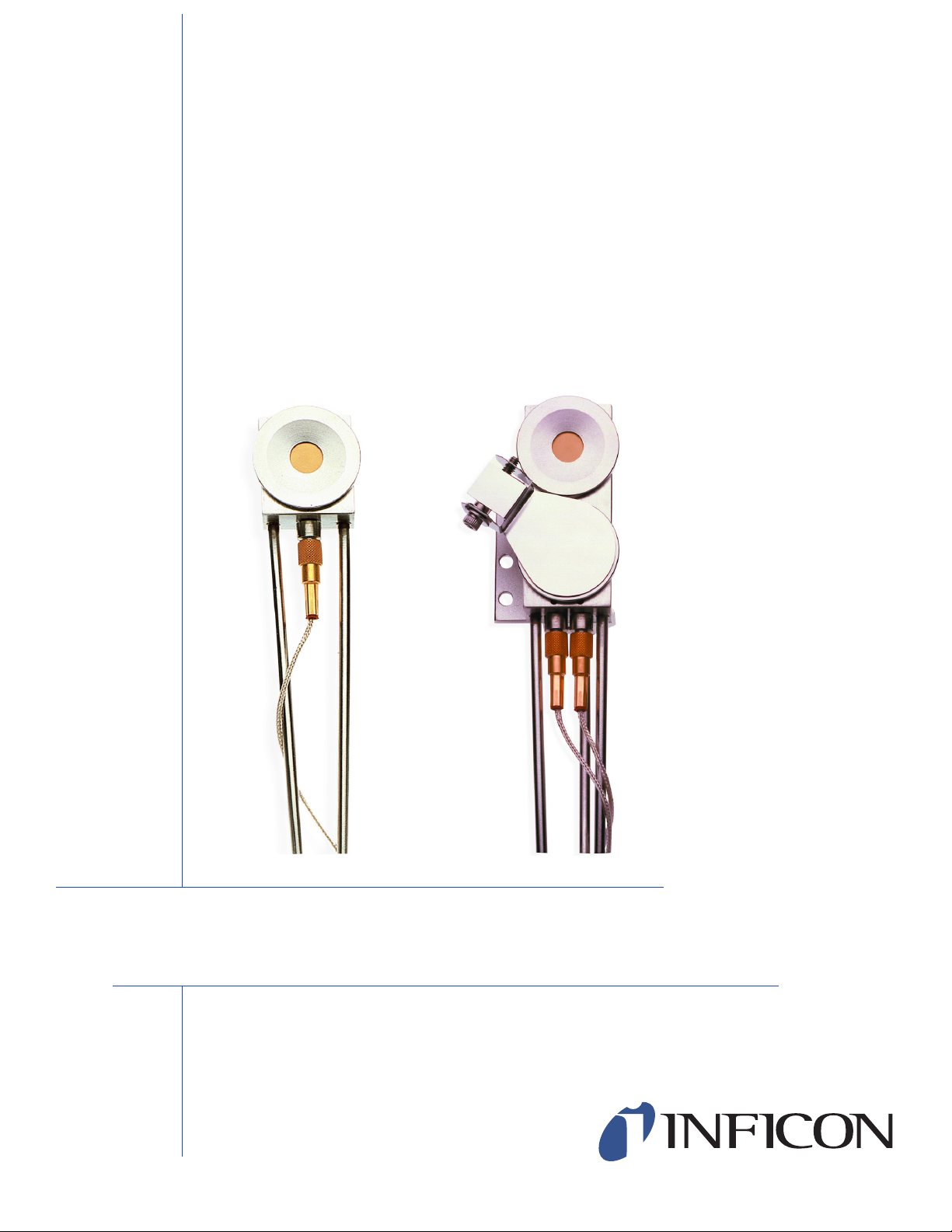
INFICON Front Load Sensors (see Figure 1-1) offer proven reliability and durability
combined with excellent thermal stability. The front load design allows for easy
insertion of the crystal holder in applications lacking sufficient room for side access.
Because they are assembled mechanically rather than soldered, parts can
conveniently be replaced in the field. Sensors can be ordered individually or in a
sensor and feedthrough combination that can be either welded or assembled with
Ultra-Torr® O-ring compression fittings.
Figure 1-1 Front Load Sensors
Front Load Single and Dual Sensors Operating Manual
Chapter 1
Introduction
The Front Load Sensor comes in two styles: Single or Dual.
The Front Load Single Sensor comes in two sensor configurations:
Standard or Right Angle (Compact).
PN 074-156N
Standard configuration—installed from the side or bottom of the chamber, with
the cooling tubes aligned parallel to the crystal face.
Right Angle configuration—installed through the top of the vacuum system,
with the water cooling tubes aligned perpendicular to the crystal face.
For the Front Load Dual Sensor, a Standard configuration (i.e., waterlines parallel
to the crystal face) is available.
Optionally, single sensors can be ordered with a pneumatically driven crystal
shutter to protect the crystal during source warm up, or when the sensor is not used
during deposition of an alternate material, or to extend crystal life when used
with RateWatcher™ or rate sampling.
NOTE: Crystal shutters are standard on Front Load Dual Sensors.
1 - 1
Page 12
Front Load Single and Dual Sensors Operating Manual
CAUTION
WARNING
1.2 Definition of Notes, Cautions and Warnings
Before using this manual, please take a moment to understand the Cautions and
Warnings used throughout. They provide pertinent information that is useful in
achieving maximum instrument efficiency while ensuring personal safety.
NOTE: Notes provide additional information about the current topic.
Failure to heed these messages could result in damage
to the instrument.
Failure to heed these messages could result in personal
injury.
1.3 How to Contact INFICON
Worldwide customer support information is available under Support >> Support
Worldwide at www.inficon.com:
Sales and Customer Service
Technical Support
Repair Service
When communicating with INFICON about a Front Load Sensor, please have the
following information readily available:
The Sales Order or Purchase Order number of the Front Load Sensor
purchase.
The Lot Identification Code, located on the side surface of the sensor head.
A description of the problem.
The exact wording of any error messages that may have been received.
An explanation of any corrective action that may have already been attempted.
PN 074-156N
1 - 2
Page 13

Front Load Single and Dual Sensors Operating Manual
1.3.1 Returning Sensor to INFICON
Do not return any sensor component to INFICON before speaking with a Customer
Support Representative and obtaining a Return Material Authorization (RMA)
number. Front Load Sensors will not be serviced without an RMA number.
Packages delivered to INFICON without an RMA number will be held until the
customer is contacted. This will result in delays in servicing the Front Load Sensor.
Prior to being given an RMA number, a completed Declaration Of Contamination
(DoC) form will be required. DoC forms must be approved by INFICON before an
RMA number is issued. INFICON may require that the sensor be sent to a
designated decontamination facility, not to the factory.
1.4 Unpacking and Inspection
1 If the Front Load Sensor has not been removed from its packaging, do so now.
The sensor and accessories are packaged in a single cardboard carton with a
rigid foam insert. Carefully remove the packaged accessories before removing
the sensor.
2 Carefully examine the sensor for damage that may have occurred during
shipping. It is especially important to note obvious rough handling on the
outside of the container. Immediately report any damage to the carrier and to
INFICON.
NOTE: Do not discard the packaging material until inventory has been taken
and installation is successful.
3 Refer to the invoice and the information contained in section 1.4.1 or section
1.4.2 on page 1-5 to take inventory.
4 To install the sensor, see Chapter 2, Sensor Installation.
5 For additional information or technical assistance, contact INFICON (refer to
section 1.3).
PN 074-156N
1 - 3
Page 14
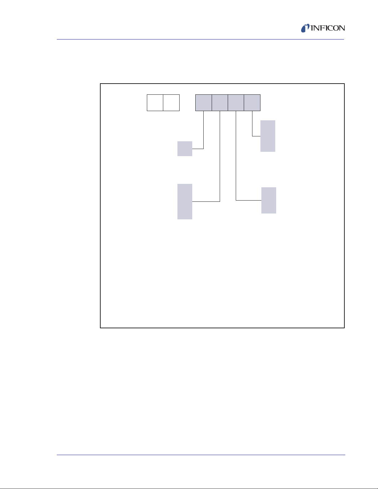
Front Load Single and Dual Sensors Operating Manual
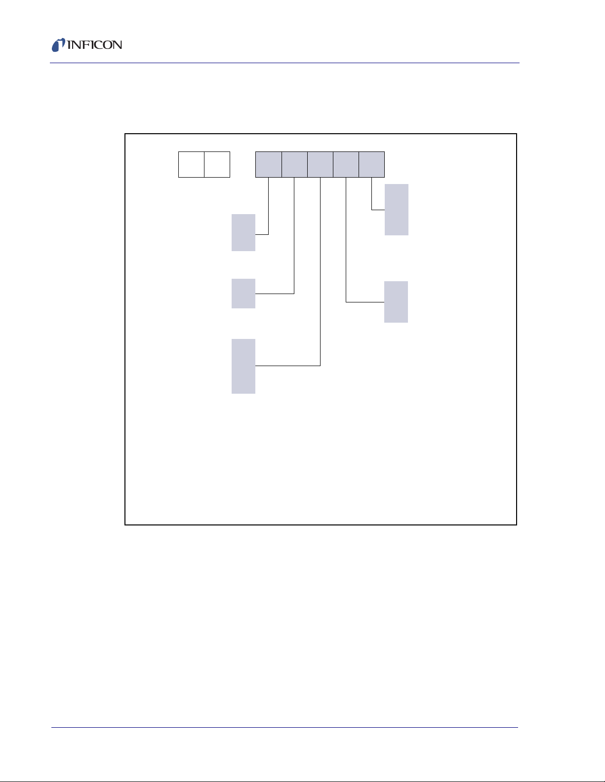
S L –
A
B
0
3
4
0
1
0
7
8
E
G
NOTE 1:
Orders for a WELDED sensor/feedthrough combination cannot
be accepted without a completed sensor length specification
form (provided by INFICON). Once a welded sensor order is
confirmed, it can not be canceled.
NOTE 2:
Feedthrough configuration varies depending on options
selected (with or without shutter, type of feedthrough, etc).
Example: SL-A0E37 uses feedthrough PN 002-042 while
SL-A1E37 uses feedthrough PN 750-030-G1.
Type of Sensor
(Includes in-vacuum cable.
Crystals sold separately.)
Standard sensor
(water lines parallel)
Right angle sensor
(water lines perpendicular)
Shutter Assembly – SEE NOTE 4
None
Standard shutter
Length of Sensor –
SEE NOTES 1 and 3
Standard length:
20.3 to 71.1 cm (8 to 28 in.)
includes 78.1 cm (30.75 in.)
in-vacuum cable. SEE NOTE 6
Extended length:
71.1 to 121.9 cm (28 to 48 in.)
includes 152.4 cm (60 in.)
in-vacuum cable. SEE NOTE 6
Feedthrough Connection –
SEE NOTE 4
Sensor not connection to
feedthrough
Sensor welded to feedthrough
Feedthrough equipped with
Ultra-Torr
®
compression fittings
(allows for adjustable sensor
length)
Feedthrough – SEE NOTE 2
None
1 in. bolt
CF40
NOTE 3:
Sensor lengths are measured from center of the crystal to the
vacuum side (sealing surface) of the feedthrough (see length
specification form).
NOTE 4:
Sensors ordered with shutters and 1 in. bolt style feedthrough can
only be welded (compression fittings not available).
NOTE 5:
Front Load sensors ordered with a CF40 feedthrough and a shutter
can not be welded due to dimensional limits of the CF40.
NOTE 6:
For sensors ordered without a weld connection (option “0” or “8”),
tubes are made to a length of approximately 76.2 cm (30 in.) for
“E” length and approximately 121.9 cm (48 in.) for “G” length
sensors.
Operation with a 152.4 cm (60 in.) cable requires a monitor /
controller with ModeLock technology (XTC/3, IC6, Cygnus 2).
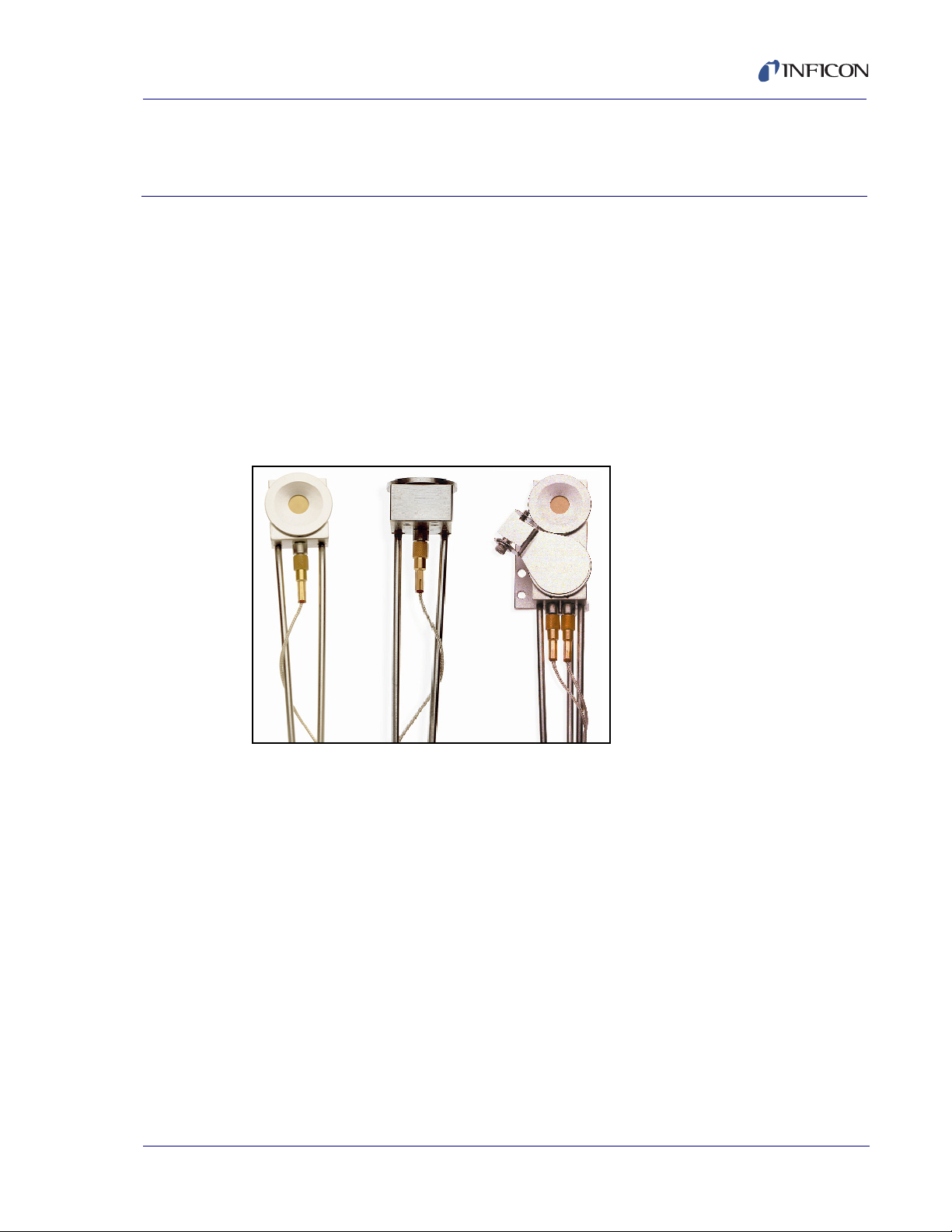
1.4.1 Single Sensor Configuration Overview and Parts
Front Load Single Sensor . . . . . . . . . . . SL-XXXXX, see Figure 1-2.
Figure 1-2 Front Load Single Sensor configurations
1 - 4
Thin Film Manuals CD . . . . . . . . . . . . . . . . . . . . . . . PN 074-5000-G1
Crystal Snatcher. . . . . . . . . . . . . . . . . . . . . . . . . . . . PN 008-007
78.1 cm (30.75 in.) In-Vacuum Cable. . . . . . . . . . . . PN 007-044
(standard length)
152.4 cm (60 in.) In-Vacuum Cable . . . . . . . . . . . . . PN 321-039-G13
(extended length)
Molybdenum Disulfide in Alcohol . . . . . . . . . . . . . . . PN 750-191-G1
(provided only with shuttered sensors)
Tube Bender Kit . . . . . . . . . . . . . . . . . . . . . . . . . . . . PN 750-037-G1
(provided only with non-welded sensors)
PN 074-156N
Page 15
Front Load Single and Dual Sensors Operating Manual
D L –
0
3
4
0
7
8
A
E
G
NOTE 1:
Orders for a WELDED sensor/feedthrough combination cannot
be accepted without a completed sensor length specification
form (provided by INFICON). Once a welded sensor order is
confirmed, it cannot be canceled.
NOTE 2:
Feedthrough configuration varies depending on options selected
(type of feedthrough and connection). Example: DL-AE37 uses
feedthrough PN 750-707-G1 while DL-AE48 uses feedthrough
PN 206-890-G2.
NOTE 3:
Sensor lengths are measured from center of the crystal closest
to the end of the sensor to the vacuum side (sealing surface) of
the feedthrough (see length specification form).
NOTE 4:
Front Load Dual Sensors ordered with a CF40 feedthrough
cannot be welded due to dimensional limits of the CF40.
NOTE 5:
For sensors ordered without a weld connection (option “0”
or “8”), tubes are made to a length of approximately 76.2 cm
(30 in.) for “E” length and approximately 121.9 cm (48 in.) for
“G” length sensors.
Operation with 152.4 cm (60 in.) in-vacuum cables requires
a monitor / controller with ModeLock technology (XTC/3, IC6,
Cygnus 2).
Type of Sensor
(Includes in-vacuum cables.
Crystals sold separately.)
Standard dual sensor
(water lines parallel to
crystal face) with shutter
Length of Sensor –
SEE NOTES 1 and 3
20.3 to 71.1 cm (8 to 28 in.)
includes two 78.1 cm (30.75 in.)
in-vacuum cables.
SEE NOTE 5
Extended length
–
71.1 to 121.9 cm (28 to 48 in.)
includes two 152.4 cm (60 in.)
in-vacuum cables.
SEE NOTE 5
Feedthrough Connection
SEE NOTE 4
Sensor not connected to
feedthrough
Sensor welded to feedthrough
Feedthrough equipped with
Ultra-Torr
®
compression fittings
(allows for adjustable sensor
length)
Feedthrough
SEE NOTE 2
None
1 in. bolt
CF40
Standard length
–
1.4.2 Dual Sensor Configuration Overview and Parts
Front Load Dual Sensor . . . . . . . . . . . . . DL-AXXX, see Figure 1-3.
Figure 1-3 Front Load Dual Sensor configurations
PN 074-156N
Thin Film Manuals CD . . . . . . . . . . . . . . . . . . . . . . . PN 074-5000-G1
Crystal Snatcher. . . . . . . . . . . . . . . . . . . . . . . . . . . . PN 008-007
78.1 cm (30.75 in.) In-Vacuum Cable. . . . . . . . . . . . PN 007-044
(standard length)
152.4 cm (60 in.) In-Vacuum Cable . . . . . . . . . . . . . PN 321-039-G13
(extended length)
Molybdenum Disulfide in Alcohol . . . . . . . . . . . . . . .PN 750-191-G1
Tube Bender Kit . . . . . . . . . . . . . . . . . . . . . . . . . . . .PN 750-037-G1
(provided only with non-welded sensors)
1 - 5
Page 16
Front Load Single and Dual Sensors Operating Manual
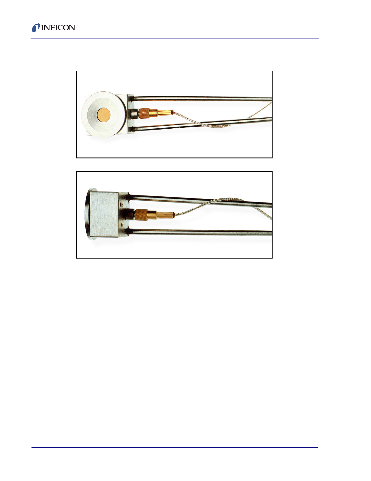
1.5 Front Load Single Sensors (PN SL-XXXXX)
Figure 1-4 Standard sensor
Figure 1-5 Right angle (compact) sensor
1 - 6
PN 074-156N
Page 17

1.5.1 Specifications
Maximum bakeout temperature
with no water . . . . . . . . . . . . . . . . . . . . . . . . . . . . . . 130°C
Maximum operating isothermal environment
temperature with minimum water flow . . . . . . . . . . . 400°C
Maximum sensor body
envelope without shutter . . . . . . . . . Standard Sensor
Water tube and
in-vacuum cable length . . . . . . . . . . Standard Length (E)
Front Load Single and Dual Sensors Operating Manual
27.00 x 61.47 x 17.53 mm
(1.06 x 2.42 x 0.69 in.)
See Figure 1-6 on page 1-10.
Right Angle Sensor
28.19 x 26.92 x 26.92 mm
(1.11 x 1.06 x 1.06 in.)
See Figure 1-8 on page 1-12.
76.2 cm (30 in.) tubes,
3.175 mm (1/8 in.) OD seamless stainless
steel, 0.406 mm (0.016 in.) wall thickness.
Includes 78.1 cm (30.75 in.) in-vacuum
cable.
Extended Length (G)
121.9 cm (48 in.) tubes,
3.175 mm (1/8 in.) OD seamless stainless
steel, 0.406 mm (0.016 in.) wall thickness.
Includes 152.4 cm (60 in.) in-vacuum cable.
Crystal exchange . . . . . . . . . . . . . . . Front-loading, self-contained package for
ease of exchange
PN 074-156N
Mounting. . . . . . . . . . . . . . . . . . . . . . Two #4-40 tapped holes on the back of the
sensor body
Crystal size. . . . . . . . . . . . . . . . . . . . 14 mm (0.550 in.) diameter
1 - 7
Page 18

1.5.2 Materials
Body and Holder . . . . . . . . . . . . . . . 304 stainless steel
Springs, Electrical Contacts . . . . . . . Au plated Be-Cu
Water Tubes. . . . . . . . . . . . . . . . . . . 304 stainless steel
In-Vacuum Cable . . . . . . . . . . . . . . . Silver coated copper, Teflon® insulated
Electrical Connector . . . . . . . . . . . . . Glass insulated
Front Load Single and Dual Sensors Operating Manual
Insulators . . . . . . . . . . . . . . . . . . . . . >99% Al
Braze . . . . . . . . . . . . . . . . . . . . . . . . Vacuum process high temperature
1.5.3 Installation Requirements
Feedthrough. . . . . . . . . . . . . . . . . . . Without Shutter
2O3
Ni-Cr alloy
Two pass water 4.8 mm (3/16 in.)
OD tubing with Microdot® coax connector
(see section 1.8.3 on page 1-25)
With Shutter
Three pass tubes (two water and one air)
4.8 mm (3/16 in.) OD tubing with Microdot
coax connector
(see section 1.8.3 on page 1-25)
Vacuum tight braze or weld joint or
connectors for the water tubes
(welded connections or connections using
Ultra-Torr® O-ring compression fittings may
be provided by INFICON if
sensor/feedthrough combination is
ordered, see Figure 1-2 on page 1-4)
1 - 8
Other . . . . . . . . . . . . . . . . . . . . . . . . XIU or oscillator to match specific
controller/monitor
The cable length from the crystal to the
oscillator should not exceed 101.6 cm
(40 in.) unless a ModeLock instrument is
used. Refer to the controller/monitor
operating manual for cable length limitations.
SL-X1XXX only: Solenoid Valve for air,
PN 750-420-G1
(see
section 3.1 on page 3-1
)
Water Flow Rate. . . . . . . . . . . . . . . . Minimum water flow 150 to 200 cm3/min,
30°C maximum
PN 074-156N
Page 19
Front Load Single and Dual Sensors Operating Manual
CAUTION
WARNING
Water Quality . . . . . . . . . . . . . . . . . . Coolant should not contain chlorides as
stress corrosion cracking may occur.
Extremely dirty water may result in loss of
cooling capacity.
Do not allow water tubes to freeze. This may happen if the
tubes pass through a cryogenic shroud and the flow of
fluid is interrupted.
Air (SL-X1XXX only). . . . . . . . . . . . . 70 psi (gauge) {85 psi (absolute)}
(5.8 bar (absolute)) [584 kPa (absolute)]
(minimum)
80 psi (gauge) {95 psi (absolute)}
(6.5 bar (absolute)) [653 kPa (absolute)]
(maximum)
Do not exceed 100 psi (gauge) {115 psi (absolute)}
(7.9 bar (absolute)) [791 kPa (absolute)].
Connection to excessive pressure may result in personal
injury or equipment damage.
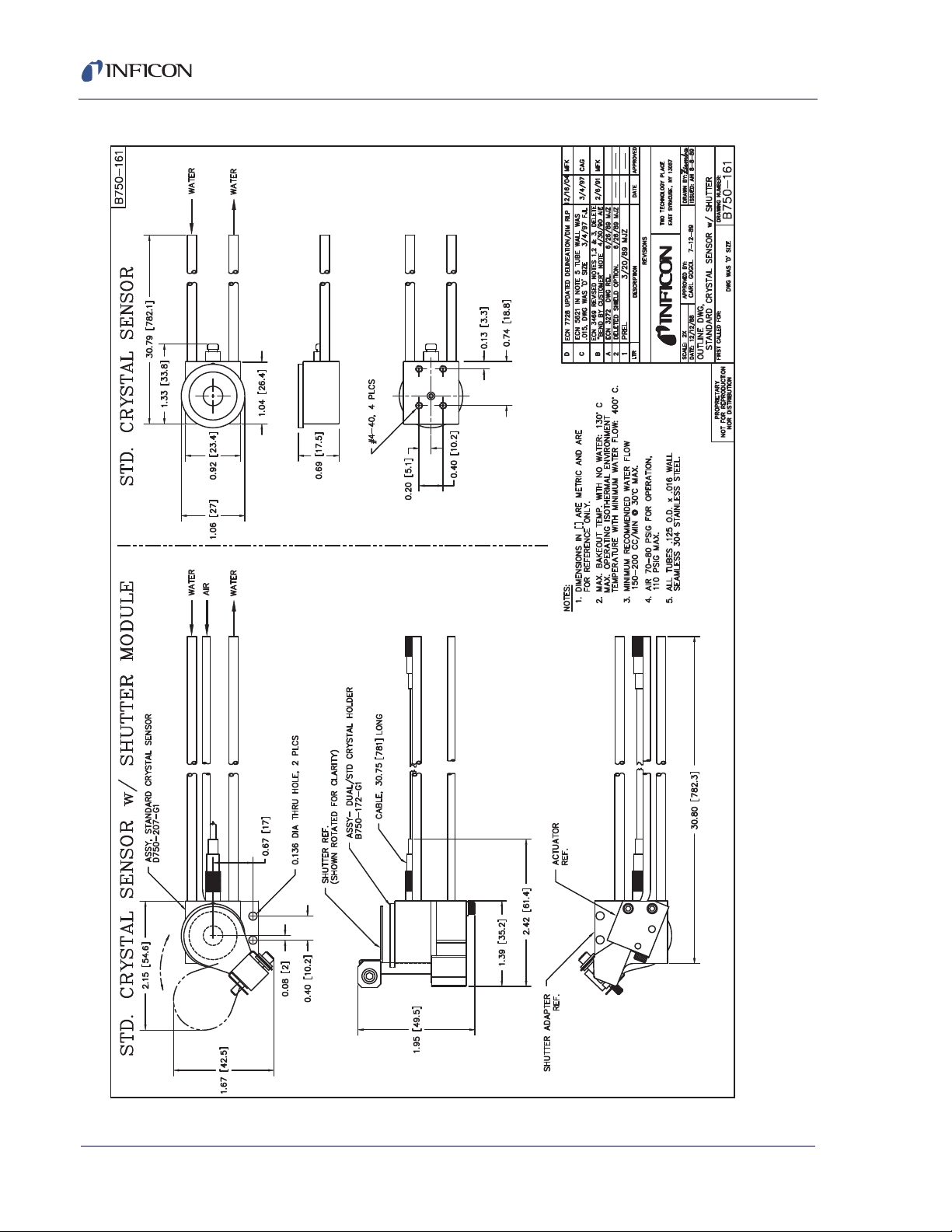
1.5.4 Single Sensor Drawings
The following Single Sensor Outline and Assembly Drawings provide dimensions
and other relevant data necessary for planning equipment configurations.
PN 074-156N
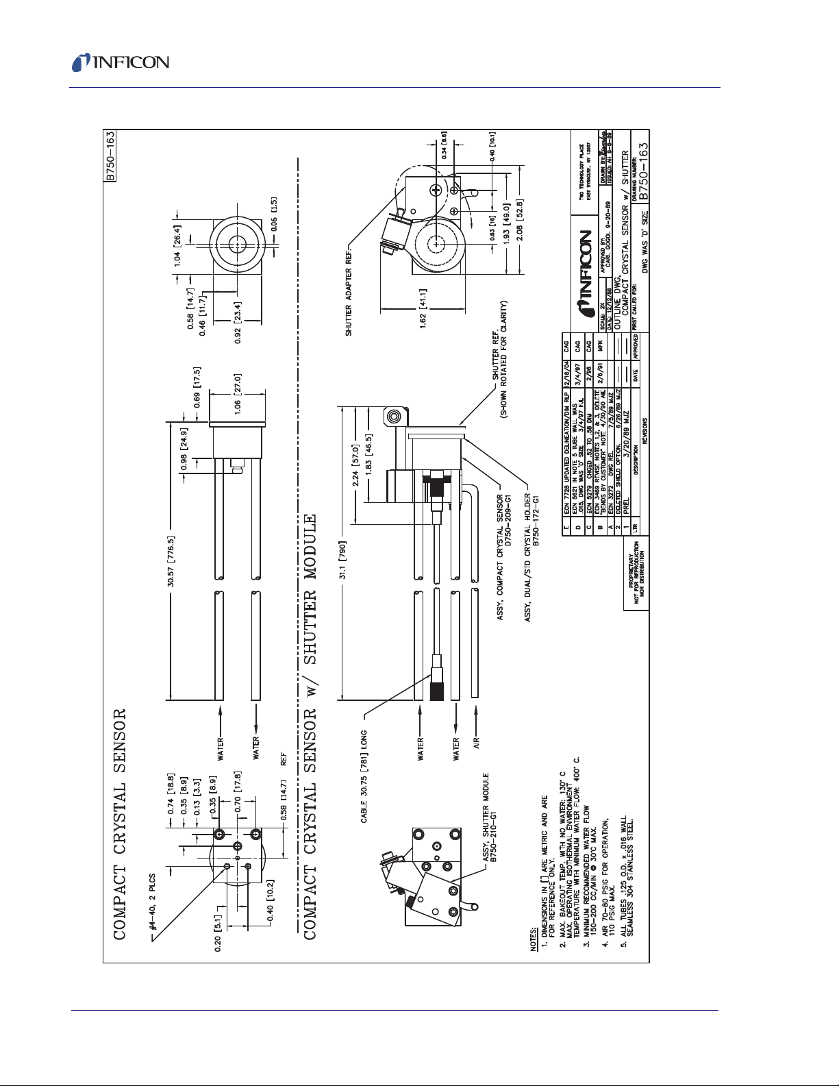
Figure 1-6 . . . . . . Standard Crystal Sensor Outline
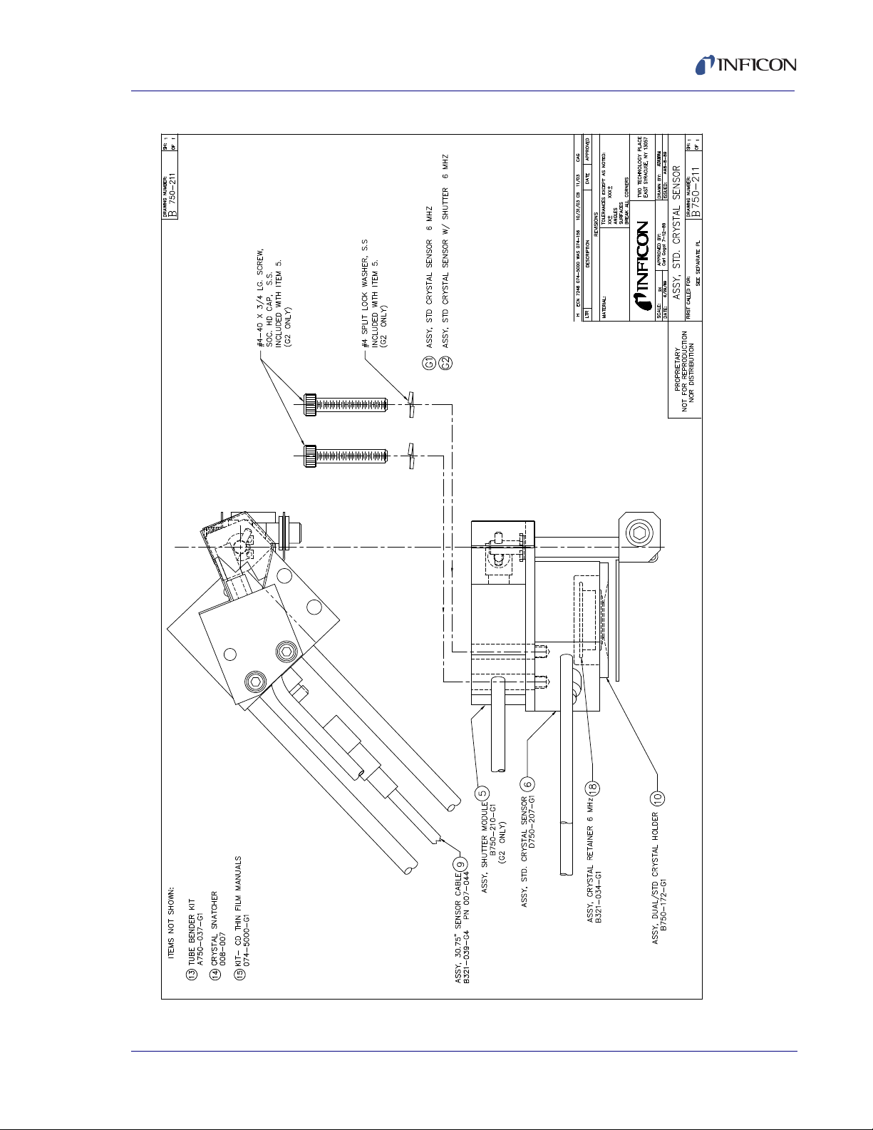
Figure 1-7 . . . . . . Standard Crystal Sensor Assembly (PN 750-211-GX)
Figure 1-8
Figure 1-9
. . . . . .Right Angle Crystal Sensor Outline
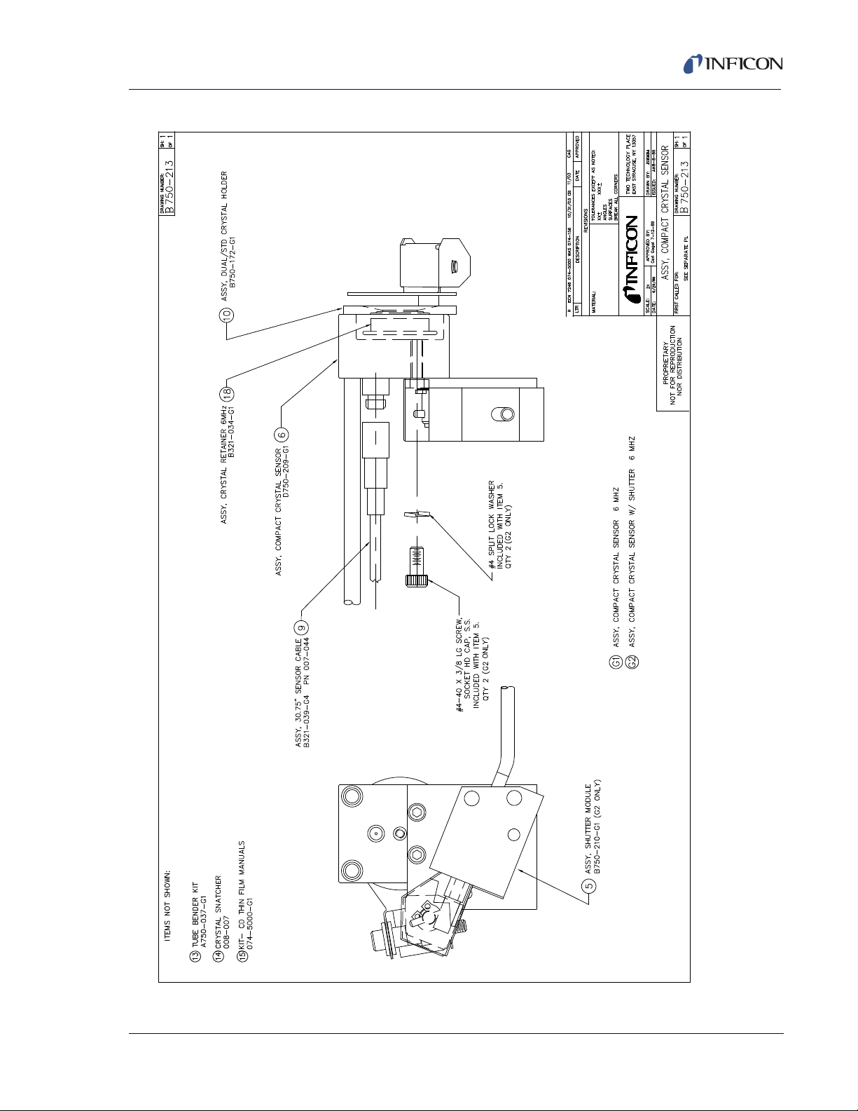
. . . . . .Right Angle Crystal Sensor Assembly (PN 750-213-GX)
1 - 9
Page 20
Front Load Single and Dual Sensors Operating Manual
U
1 - 10
Figure 1-6 Standard crystal sensor outline
PN 074-156N
Page 21
Front Load Single and Dual Sensors Operating Manual
Figure 1-7 PN 750-211-GX standard crystal sensor assembly
PN 074-156N
1 - 11
Page 22
Front Load Single and Dual Sensors Operating Manual
1 - 12
Figure 1-8 Right angle crystal sensor outline
PN 074-156N
Page 23
Front Load Single and Dual Sensors Operating Manual
,
Figure 1-9 PN 750-213-GX right angle crystal sensor assembly
PN 074-156N
1 - 13
Page 24
Front Load Single and Dual Sensors Operating Manual
Sensor 2 (Secondary)Sensor 1 (Primary) Sensor 1
Sensor 2
1.6 Front Load Dual Sensor (PN DL-AXXX)
Figure 1-10 Front Load Dual Sensor
1.6.1 Specifications
Maximum bakeout temperature with no water . . . . . 130°C
Maximum operating isothermal environment
temperature with minimum water flow . . . . . . . . . . . 400°C
Maximum sensor body envelope . . . . . . . . . . . . . . . 39.12 x 82.04 x 49.54 mm
(1.54 x 3.23 x 1.95 in.)
Water tube and
in-vacuum cable length . . . . . . . . . . Standard Length (E)
76.2 cm (30 in.) tubes, 3.175 mm (1/8 in.) OD
seamless stainless steel, 0.406 mm
(0.016 in.) wall thickness.
Includes 78.1 cm (30.75 in.) in-vacuum
cable.
Extended Length (G)
121.9 cm (48 in.) tubes,
3.175 mm (1/8 in.) OD seamless stainless
steel, 0.406 mm (0.016 in.) wall thickness.
Includes 152.4 cm (60 in.) in-vacuum cable.
Crystal exchange . . . . . . . . . . . . . . . Front-loading, self-contained package for
ease of exchange. Shutter flips up to ease
access to the holders.
Mounting . . . . . . . . . . . . . . . . . . . . . Three #4-40 tapped holes
Crystal size. . . . . . . . . . . . . . . . . . . . 14 mm (0.550 in.) diameter
PN 074-156N
1 - 14
Page 25

1.6.2 Materials
Body and Holder . . . . . . . . . . . . . . . 304 stainless steel
Springs, Electrical Contacts . . . . . . . Au plated Be-Cu
Water Tubes and Air Tube . . . . . . . . 304 stainless steel
In-Vacuum Cable . . . . . . . . . . . . . . . Silver coated copper, Teflon
Electrical Connector . . . . . . . . . . . . . Glass insulated
Front Load Single and Dual Sensors Operating Manual
insulated
Insulators . . . . . . . . . . . . . . . . . . . . . >99% Al
Other Mechanical Parts . . . . . . . . . . 304 or 18-8 stainless steel
Braze . . . . . . . . . . . . . . . . . . . . . . . . Vacuum process high temperature
1.6.3 Installation Requirements
Feedthrough . . . . . . . . . . . . . . . . . . . Three pass tubes (two water and one air)
Other . . . . . . . . . . . . . . . . . . . . . . . . Two XIUs or oscillators designed to interface
2O3
Ni-Cr alloy
4.8 mm (3/16 in.) OD tubing with two
Microdot coax connectors
(see section 1.8.3 on page 1-25)
Vacuum tight braze or weld joint or
connectors for the water tubes
(welded connections or connections using
Ultra-Torr® O-ring compression fittings may
be provided by INFICON if
sensor/feedthrough combination is
ordered, see Figure 1-3 on page 1-5)
with the deposition controller or one XIU or
oscillator and one CrystalTwo switch
(not compatible with all controllers/monitors)
PN 074-156N
The cable length from the crystal to the
oscillator should not exceed 101.6 cm
(40 in.) unless a ModeLock instrument is
used. Refer to the controller/monitor
operating manual for cable length limitations.
Solenoid valve assembly for air,
PN 750-420-G1
(see section 3.1 on page 3-1)
Water Flow Rate. . . . . . . . . . . . . . . . Minimum water flow 150 to 200 cm
3
/min,
30°C maximum
1 - 15
Page 26
Front Load Single and Dual Sensors Operating Manual
CAUTION
WARNING
Water Quality . . . . . . . . . . . . . . . . . . Coolant should not contain chlorides as
stress corrosion cracking may occur.
Extremely dirty water may result in loss of
cooling capacity.
Do not allow water tubes to freeze. This may happen if the
tubes pass through a cryogenic shroud and the flow of
fluid is interrupted.
Air Pressure . . . . . . . . . . . . . . . . . . . 70 psi (gauge) {85 psi (absolute)}
(5.8 bar (absolute)) [584 kPa (absolute)]
(minimum)
80 psi (gauge) {95 psi (absolute)}
(6.5 bar (absolute)) [653 kPa (absolute)]
(maximum)
Do not exceed 100 psi (gauge) {115 psi (absolute)}
(7.9 bar (absolute)] [791 kPa (absolute)].
Connection to excessive pressure may result in personal
injury or equipment damage.
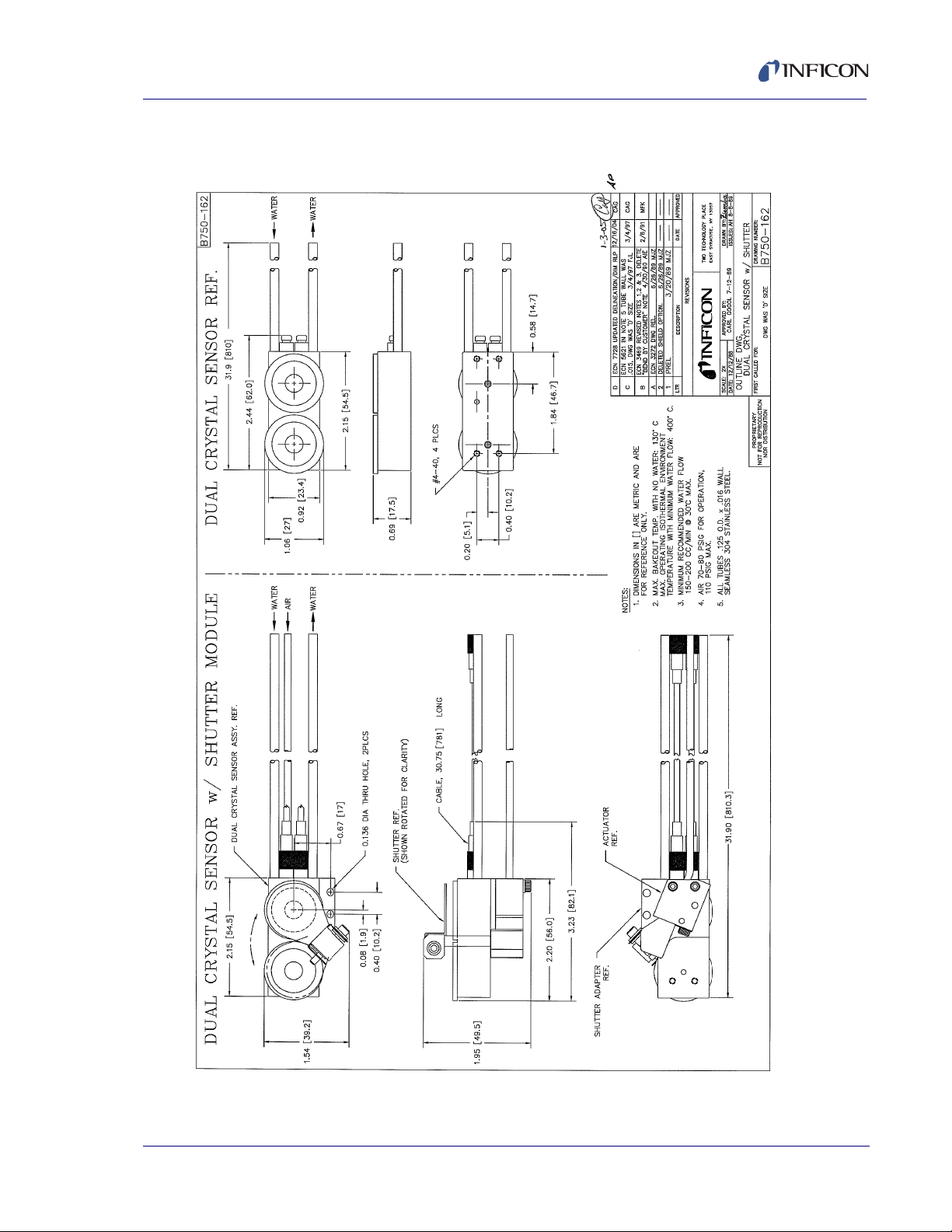
1.6.4 Dual Sensor Drawings
The following Dual Sensor Outline and Assembly Drawings provide dimensions
and other relevant data necessary for planning equipment configurations.
Figure 1-11. . . . . Dual Crystal Sensor Outline
Figure 1-12. . . . . Dual Crystal Sensor Assembly (PN 750-212-GX)
PN 074-156N
1 - 16
Page 27
Front Load Single and Dual Sensors Operating Manual
Figure 1-11 Dual crystal sensor outline
PN 074-156N
1 - 17
Page 28

Front Load Single and Dual Sensors Operating Manual
1 - 18
Figure 1-12 PN 750-212-GX dual crystal sensor assembly
PN 074-156N
Page 29

Front Load Single and Dual Sensors Operating Manual
WARNING
1.7 Shutter Module (PN 750-210-G1 and 750-210-G3)
Figure 1-13 Shutter module
1.7.1 Specifications
Maximum bakeout temperature
with no water . . . . . . . . . . . . . . . . . . 130°C
Maximum operating isothermal
environment temperature,
properly attached to a sensor
with minimum water flow . . . . . . . . . 400°C
Air Tube . . . . . . . . . . . . . . . . . . . . . . 304-SS, 3.175 mm (1/8 in.) OD seamless
stainless steel, 0.406 mm (0.016 in.) wall
thickness
PN 750-210-G1 . . . . . . . . . . . . . 76.2 cm (30 in.) air tube
PN 750-210-G3 . . . . . . . . . . . . . 121.9 cm (48 in.) air tube
Pressure . . . . . . . . . . . . . . . . . . . . . . 70 psi (gauge) {85 psi (absolute)}
(5.8 bar (absolute)) [584 kPa (absolute)]
(minimum)
80 psi (gauge) {95 psi (absolute)}
(6.5 bar (absolute)) [653 kPa (absolute)]
(maximum)
PN 074-156N
Do not exceed 100 psi (gauge) {115 psi (absolute)}
(7.9 bar (absolute)) [791 kPa (absolute)]. Connection to
excessive pressure may result in personal injury or
equipment damage.
Materials. . . . . . . . . . . . . . . . . . . . . . Stainless steel
Shutter . . . . . . . . . . . . . . . . . . . . . . . Pneumatically operated. Shutter swings
aside for easy crystal exchange.
Braze . . . . . . . . . . . . . . . . . . . . . . . . Vacuum process high temperature
(BNi-2 and Ni-Cr alloy)
1 - 19
Page 30

Front Load Single and Dual Sensors Operating Manual
1.7.2 Shutter Module Drawings
The following Shutter Module Assembly Drawings provide relevant data necessary
for planning equipment configurations.
Figure 1-14. . . . . . . . . . . . . . . . . . . . PN 750-210-G1, 76.2 cm (30 in.)
Figure 1-15. . . . . . . . . . . . . . . . . . . . PN 750-210-G3, 121.9 cm (48 in.)
Shutter Module
Shutter Module
1 - 20
PN 074-156N
Page 31

Front Load Single and Dual Sensors Operating Manual
Figure 1-14 PN 750-210-G1, 76.2 cm (30 in.) shutter module
PN 074-156N
1 - 21
Page 32

Front Load Single and Dual Sensors Operating Manual
1 - 22
Figure 1-15 PN 750-210-G3, 121.9 cm (48 in.) shutter module
PN 074-156N
Page 33

Front Load Single and Dual Sensors Operating Manual
1.8 Feedthroughs
NOTE: Sensor/feedthrough combination temperature specifications are limited by
lowest temperature specification of the component.
1.8.1 Specifications for 2.54 cm (1 in.) Bolt
Mounting. . . . . . . . . . . . . . . . . . . . . . 25.781 mm (1.015 in.) ±0.254 mm (0.010 in.)
diameter aperture
Ultra-Torr O-ring compression fitting terminations
Maximum operational
environment temperature
with no water . . . . . . . . . . . . . . . . . . 165°C
Maximum operational
environment temperature
with minimum water flow . . . . . . . . . 300°C
Materials. . . . . . . . . . . . . . . . . . . . . . 304 stainless steel, Teflon, glass, brass,
beryllium copper, VITON®
Welded terminations
Maximum operational
environment temperature
with no water . . . . . . . . . . . . . . . . . . 165°C
Maximum operational
environment temperature
with minimum water flow . . . . . . . . . 450°C
Materials. . . . . . . . . . . . . . . . . . . . . . 304 stainless steel, Teflon, glass, brass,
beryllium copper
PN 074-156N
1 - 23
Page 34

Front Load Single and Dual Sensors Operating Manual
1.8.2 Specifications for CF40 (2-3/4 in. ConFlat)
Mounting . . . . . . . . . . . . . . . . . . . . . Mates with 7 cm (2-3/4 in.) ConFlat® type
flanges with 3.49 cm (1.375 in.) ID
(minimum)
Ultra-Torr O-ring compression fitting terminations
Maximum operational
environment temperature
with no water . . . . . . . . . . . . . . . . . . 165°C
Maximum operational
environment temperature
with minimum water flow . . . . . . . . . 300°C
Materials. . . . . . . . . . . . . . . . . . . . . . 304 stainless steel, Teflon, glass, brass,
beryllium copper, VITON®
Welded terminations
Maximum operational
environment temperature
with no water . . . . . . . . . . . . . . . . . . 165°C
Maximum operational
environment temperature
with minimum water flow . . . . . . . . . 450°C
Materials. . . . . . . . . . . . . . . . . . . . . . 304 stainless steel, Teflon, glass, brass,
beryllium copper
PN 074-156N
1 - 24
Page 35

Front Load Single and Dual Sensors Operating Manual
1.8.3 Feedthrough Drawings
The following Feedthrough Outline Drawings provide dimensions
and other pertinent data necessary for planning equipment configurations.
Figure 1-16 . . . . . 2.54 cm (1 in.) bolt feedthrough with two tubes, one coax
(PN 002-042)
Figure 1-17 . . . . . 2.54 cm (1 in.) bolt feedthrough with three tubes, one coax
(PN 750-030-G1)
Figure 1-18 . . . . . 2.54 cm (1 in.) bolt feedthrough with three tubes, two coax
(PN 750-707-G1)
Figure 1-19 . . . . . 2.54 cm (1 in.) bolt feedthrough with two tubes, 1 coax,
with Ultra-Torr (PN 750-624-G1)
Figure 1-20 . . . . . CF40 (2-3/4 in. ConFlat) feedthrough with two tubes, one coax
(PN 002-043)
Figure 1-21 . . . . . CF40 (2-3/4 in. ConFlat) feedthrough with three tubes, one coax
(PN 750-685-G1)
Figure 1-22 . . . . . CF40 (2-3/4 in. ConFlat) feedthrough with three tubes, two coax
(PN 002-080)
Figure 1-23 . . . . . CF40 (2-3/4 in. ConFlat) feedthrough with two tubes, one coax,
with Ultra-Torr (PN 206-878-G2)
Figure 1-24 . . . . . CF40 (2-3/4 in. ConFlat) feedthrough with three tubes, one
coax, with Ultra-Torr (PN 750-685-G2)
Figure 1-25 . . . . . CF40 (2-3/4 in. ConFlat) feedthrough with three tubes, two
coax, with Ultra-Torr (PN 206-890-G2)
PN 074-156N
1 - 25
Page 36

Front Load Single and Dual Sensors Operating Manual
19.0 (0.75)
Coax Connector
Viton O-ring
#2-122
#1-14-UNS Thread
127.0 (5.00)
Assembly
BNC Connector
View A-A
127.0 (5.00)
9.7 (0.38)
50.8 (2.00)
323.8 (12.75)
Washer
19.0 (0.75)
10.16 (0.400)
5.08 (0.200)
3.96
(0.156)
5.08
(0.200)
Dimensions are shown
millimeter (inch)
AA
Figure 1-16 2.54 cm (1 in.) bolt feedthrough with two tubes, one coax (PN 002-042)
1 - 26
PN 074-156N
Page 37

Front Load Single and Dual Sensors Operating Manual
19.0 (0.75)
Coax Connector
Viton O-ring #2-122
#1-14-UNS Thread
127.0 (5.00)
BNC Connector
View A-A
127.0 (5.00)
9.7 (0.38)
50.8 (2.00)
323.8
(12.75)
Washer
19.0 (0.75)
12.70 (0.500)
6.35 (0.250)
7.11
(0.280)
3.18
(0.125)
AA
4.78
(0.188)
Dimensions are shown
millimeter (inch)
Mating air fitting (10-32) for
PN 750-420-G1 Solenoid Valve
Figure 1-17 2.54 cm (1 in.) bolt feedthrough with three tubes, one coax (PN 750-030-G1)
PN 074-156N
1 - 27
Page 38

Front Load Single and Dual Sensors Operating Manual
BNC Connector
75.31
(2.96)
50.80
(2.00)
127.00
(5.00)
304.80
(12.00)
BNC Connector
7.11
(0.28)
Coax Connector
126.11
(4.96)
1.52
(0.06)
7.80
(0.31)
7.14
(0.28)
3.56
(0.14)
14.27
(0.56)
7.11
(0.28)
38.19
(1.50)
# 25.4 (1.0)
1 - 14 UNS Thread
9.65
(0.38)
Dimensions are shown
millimeter (inch)
Washer
Figure 1-18 2.54 cm (1 in.) bolt feedthrough with three tubes, two coax (PN 750-707-G1)
PN 074-156N
1 - 28
Page 39

Front Load Single and Dual Sensors Operating Manual
251.83
(9.91)
162.93
(6.41)
76.20
(3.00)
50.80
(2.00)
3.25
(0.13)
12.70
(0.50)
61.85
(2.44)
9.04
(0.36)
43.99
(1.73)
38.10
(1.50)
10.16
(0.40)
5.08
(0.20)
Dimensions are shown
millimeter (inch)
# 25.4 (1.0)
1-14 UNS Thread
Washer
Ultra-Torr
Fittings (2)
BNC Connector
Coax
Connector
Figure 1-19 2.54 cm (1 in.) bolt feedthrough with two tubes, one coax, with Ultra-Torr (PN 750-624-G1)
PN 074-156N
1 - 29
Page 40

Front Load Single and Dual Sensors Operating Manual
Coax Connector
127.00
(5.00)
BNC Connector
228.60
(9.00)
12.70 (0.5)
6.73 (0.26) Diameter
Six holes equally spaced
on a 58.71 (2.31) diameter
bolt circle
5.1
(0.20)
10.2
(0.40)
7.6 (0.30)
69.85
(2.75)
15.2 (0.60)
70 (2-3/4) ConFlat Flange
32.8
(1.29)
Seamless Tube (3)
4.78 OD, 3.33 ID
(0.188 OD), (0.131 ID)
Dimensions are shown
millimeter (inch)
Figure 1-20 CF40 (2-3/4 in. ConFlat) feedthrough with two tubes, one coax (PN 002-043)
PN 074-156N
1 - 30
Page 41

Front Load Single and Dual Sensors Operating Manual
32.64
(1.29)
57.15
(2.25)
12.70
(0.50)
127.00
(5.00)
228.60
(9.00)
15.24
(0.60)
7.66
(0.30)
8.89
(0.35)
12.70
(0.50)
8.89
(0.35)
CF40 70 (2-3/4) ConFlat Flange
Dimensions are shown
millimeter (inch)
0.26 (6.73) diameter
Six holes equally spaced
on a 2.31 (58.71) diameter
bolt circle
BNC Connector
Coax Connector
69.85
(2.75)
Mating air fitting
(10-32) for
PN 750-420-G1
Solenoid Valve
Figure 1-21 CF40 (2-3/4 in. ConFlat) feedthrough with three tubes, one coax (PN 750-685-G1)
PN 074-156N
1 - 31
Page 42

Front Load Single and Dual Sensors Operating Manual
54.61
(2.15)
BNC Connector (2)
127.00
(5.00)
228.60
(9.00)
Seamless Tube (3)
4.78 OD, 3.33 ID
(0.188 OD), (0.131 ID)
Coax Connector (2)
Mating air fitting (10-32) for
PN 750-420-G1 Solenoid Valve
12.70 (0.5)
6.73 (0.26) Diameter
Six holes equally spaced
on a 58.71 (2.31) diameter
bolt circle
69.85
(2.75)
22.86 (0.90)
11.43 (0.45)
7.925 (0.312)
Hexagonal
5.08 (0.20)
11.53 (0.45)
10.16 (0.40)
Dimensions are shown
millimeter (inch)
Figure 1-22 CF40 (2-3/4 in. ConFlat) feedthrough with three tubes, two coax (PN 002-080)
CF40 70 (2-3/4) ConFlat Flange
10.16 (0.40)
PN 074-156N
1 - 32
Page 43

Front Load Single and Dual Sensors Operating Manual
251.83
(9.91)
127.00
(5.00)
32.64
(1.29)
12.70
(0.50)
15.24
(0.60)
10.24
(0.40)
5.08
(0.20)
7.62
(0.30)
Dimensions are shown
millimeter (inch)
0.26 (6.73) Diameter
Six holes equally spaced
on a 2.31 (58.71) diameter
bolt circle
CF40 70 (2-3/4)
ConFlat Flange
BNC Connector
Coax Connector
69.85
(2.75)
Ultra-Torr Fittings (2)
Figure 1-23 CF40 (2-3/4 in. ConFlat) feedthrough with two tubes, one coax, with Ultra-Torr (PN 206-878-G2)
PN 074-156N
1 - 33
Page 44

Front Load Single and Dual Sensors Operating Manual
32.64
(1.29)
12.70
(0.50)
57.15
(2.25)
127.00
(5.00)
7.62
(0.30)
15.24
(0.60)
8.89
(0.35)
6.73
(0.26)
8.89
(0.35)
251.61
(9.91)
CF40 70 (2-3/4) ConFlat Flange
Coax Connector
BNC Connector
6.73 (0.26) Diameter
Six holes equally spaced
on a 58.71 (2.31) diameter
bolt circle
69.85
(2.75)
Dimensions are shown
millimeter (inch)
Mating air fitting
(10-32) for
PN 750-420-G1
Solenoid Valve
Ultra-Torr Fittings (3)
Figure 1-24 CF40 (2-3/4 in. ConFlat) feedthrough with three tubes, one coax, with Ultra-Torr (PN 750-685-G2)
PN 074-156N
1 - 34
Page 45

Front Load Single and Dual Sensors Operating Manual
57.15
(2.25)
32.64
(1.29)
165.10
(6.50)
251.83
(9.91)
12.70
(0.50)
38.10
(1.50)
TYP 3 PLCS
10.16
(0.40)
11.43
(0.45)
5.08
(0.20)
11.43
(0.45)
32.64
(1.29)
Mating air fitting (10-32) for
PN 750-420-G1 Solenoid Valve
CF 40 70 (2-3/4)
ConFlat Flange
Coax Connector (2)
BNC Connector (2)
6.73 (0.26) Diameter
Six holes equally spaced
on a 58.71 (2.31) diameter
bolt circle
Dimensions are shown
millimeter (inch)
69.85
(2.75)
Ultra-Torr Fittings (3)
Figure 1-25 CF40 (2-3/4 in. ConFlat) feedthrough with three tubes, two coax, with Ultra-Torr (PN 206-890-G2)
PN 074-156N
1 - 35
Page 46

Front Load Single and Dual Sensors Operating Manual
This page is intentionally blank.
1 - 36
PN 074-156N
Page 47

Front Load Single and Dual Sensors Operating Manual
2.1 Pre-installation Sensor Check
Prior to installing the sensor in the vacuum system, make certain that it is
in proper working condition by following the appropriate procedure.
2.1.1 Sensor Check with XTC/3, IC6, or Cygnus 2 Deposition Controller
1 Connect the in-vacuum cable from the sensor head to the feedthrough
or a coax adapter (Microdot/BNC).
2 Connect one end of the 15.2 cm (6 in.) BNC cable (PN 755-257-G6)
to the BNC connector on the feedthrough.
3 Connect the other end of the 15.2 cm (6 in.) BNC cable
to the connector of the ModeLock oscillator (XIU) (PN 781-600-GX).
Chapter 2
Sensor Installation
4 Connect one end of the XIU cable (PN 600-1261-PXX)
to the mating connector of the XIU.
5 Connect the other end of the XIU cable to a sensor channel
at the rear of the controller.
6 Install the crystal as instructed by section 4.2 on page 4-2.
7 Connect power to the controller.
8 Set the power switch to ON.
9 Set density at 1.00 g/cm
3
.
10 Zero the thickness. The display should indicate 0 or ± 0.001 kÅ.
Crystal life should read from 0 to 5%.
PN 074-156N
11 Breathe heavily on the crystal. A thickness indication of 1.000 to 2.000 kÅ
should display. When the moisture evaporates, the thickness indication should
return to approximately zero. If these conditions are observed, the sensor is in
proper working order and may be installed (see section 2.2 on page 2-4).
2 - 1
Page 48

Front Load Single and Dual Sensors Operating Manual
2.1.2 Sensor Check with STM-2XM, STM-3, SQM-160, SQC-310, SQM-242, or IQM-233 Deposition Controller/Monitor
1 Connect the in-vacuum cable from the sensor head to the feedthrough
or a coax adapter (Microdot/BNC).
2 Connect one end of the 15.2 cm (6 in.) BNC cable (PN 782-902-011)
to the BNC connector on the feedthrough.
3 Connect the other end of the 15.2 cm (6 in.) BNC cable to the connector
of the oscillator (PN 782-900-010 or 783-500-013) labeled Feedthrough or
Sensor.
4 Connect one end of the oscillator cable (PN 782-902-012-XX)
to the mating connector of the oscillator labeled Instrument or Control Unit.
5 Connect the other end of the oscillator cable to a sensor connector
at the rear of the controller/monitor.
6 Install the crystal as instructed by section 4.2 on page 4-2.
7 Connect power to the controller.
8 Set the power switch to ON.
9 For the SQM-242 card, IQM-233 card, or STM-3, launch the appropriate
software.
10 Set density at 1.00 g/cm
3
.
11 Zero the thickness. The display should indicate 0 or ± 0.001 kÅ.
Crystal life should read from 95 to 100%.
12 Breathe heavily on the crystal. A thickness indication of 1.000 to 2.000 kÅ
should display. When the moisture evaporates, the thickness indication should
return to approximately zero. If these conditions are observed, the sensor is in
proper working order and may be installed (see section 2.2 on page 2-4).
PN 074-156N
2 - 2
Page 49

Front Load Single and Dual Sensors Operating Manual
2.1.3 Sensor Check with Q-pod™ or STM-2 Deposition Monitor
1 Connect the in-vacuum cable from the sensor head to the feedthrough
or a coax adapter (Microdot/BNC).
2 Connect one end of the 15.2 cm (6 in.) BNC cable (PN 782-902-011)
to the BNC connector on the feedthrough.
3 Connect the other end of the 15.2 cm (6 in.) BNC cable to the connector
of the Q-pod or STM-2.
4 Connect one end of the USB cable (PN 068-0472) to the mating connector
of the Q-pod or STM-2.
5 Connect the other end of the USB cable to a USB port on the computer being
used to operate the Q-pod or STM-2.
6 Install the crystal as instructed by section 4.2 on page 4-2.
7 Launch the appropriate monitor software.
8 Set density at 1.00 g/cm
9 Zero the thickness. The display will indicate 0 or ± 0.001 kÅ. Crystal life should
read from 95 to 100%. The green indicator on the Q-pod or STM-2 should be
illuminated.
3
.
10 Breathe heavily on the crystal. A thickness indication of 1.000 to 2.000 kÅ
should display. When the moisture evaporates, the thickness indication should
return to approximately zero. If these conditions are observed, the sensor is in
proper working order and may be installed (see section 2.2).
PN 074-156N
2 - 3
Page 50

Front Load Single and Dual Sensors Operating Manual
WARNING
2.1.4 Sensor Shutter Check
Temporarily connect an air supply to the actuator air tube. Use the manual override
button on the solenoid valve (see Figure 3-2 on page 3-5 or Figure 3-3 on page
3-6), or other means, to activate and deactivate the pneumatic shutter several
times.
NOTE: The air supply must be 70 psi (gauge) {85 psi (absolute)}
(5.8 bar (absolute) [584 kPa (absolute)] (minimum) to 80 psi (gauge)
{95 psi (absolute)} (6.5 bar (absolute)) [653 kPa (absolute)] (maximum).
Do not exceed 100 psi (gauge) {115 psi (absolute)}
(7.9 bar (absolute)) [791 kPa (absolute)].
Connection to excessive pressure may result in personal
injury or equipment damage.
When activated, shutter movement should be smooth, rapid, complete, and the
shutter should completely expose the crystal opening. When deactivated, the
shutter should completely cover the crystal opening. Repositioning of the shutter
may be required to achieve optimum positioning. To adjust the position of the
shutter on the shutter shaft, loosen the socket screw on the shutter assembly,
rotate the shutter to the desired position, and tighten the socket screw.
NOTE: A Solenoid Valve (PN 750-420-G1) is required with any new shutter
installation. See Chapter 3 for more information on the Solenoid Valve
and its installation.
2.2 Sensor Installation Guidelines
Install the sensor as far as possible from the evaporation source (a minimum of
25.4 cm or 10 in.) while keeping the sensor in a position well within the evaporant
stream to accumulate thickness at a rate proportional to accumulation on the
substrate. Figure 2-2 on page 2-6 shows proper and improper methods of installing
sensors.
Plan the installation to ensure that there are no obstructions blocking a direct path
between the sensor and the source.
For best process reproducibility, support the sensor so that it cannot move during
maintenance and crystal replacement.
PN 074-156N
2 - 4
Figure 2-1 shows the typical installation of an INFICON water-cooled crystal sensor
in the vacuum process chamber. Use the illustration and the following guidelines to
install sensors for optimum performance and convenience.
Page 51

Figure 2-1 Typical installation
>
Mounting Brackett
In-Vacuum Cable
(Routed with
water tubes)
Braze/Weld Joint
or Compression Fittings
Source to Sensor
(25.4 cm (10 in.) minimum)
Sensor
Shutter
Source
Pneumatic
Actuator
PN 750-420-G1
Solenoid
Valve
Instrument Chassis
To
Source Controller
XIU or Oscillator
To
Instrument
Chassis
Water In
Water Out
Air Supply
Source
Shutter
Front Load Single and Dual Sensors Operating Manual
PN 074-156N
2 - 5
Page 52

Front Load Single and Dual Sensors Operating Manual
Correct
Incorrect
Correct
Incorrect
Incorrect
Obstruction
Source
The sensor head must be installed such that the face of the crystal is perpendicular
to the evaporant stream from the source (see Figure 2-2). Two effects may arise if
the sensor head is not perpendicular to the evaporant stream, and the combination
of these effects will have a negative effect on crystal life and increase the
probability of mode hops:
The deposit will not be even across the crystal surface. The edge of the crystal
that is angled away from the source is farther away from the source and
receives less material, causing the thickness of the deposit to become wedge
shaped. This wedge shape in the deposited film tends to reduce the activity of
the crystal at its primary resonance.
The area of the deposit shifts from the center of the crystal. This is due to the
shadowing effect of the crystal aperture. If the crystal is not square to the
evaporant stream, the strength of spurious (non-thickness shear) modes of
vibration are enhanced. If the activity of these spurious modes of oscillation
become strong enough, they cause short-term perturbation of the fundamental
frequency. If they get very strong, the oscillator can lock onto the spurious
mode of oscillation, causing a mode hop.
Figure 2-2 Sensor installation guidelines
2 - 6
To guard against spattering, use a source shutter to shield the sensor during initial
soak periods. If the crystal is hit with only a very small particle of molten material,
it may be damaged and stop oscillating. Even in cases when it does not completely
stop oscillating, the crystal may immediately become unstable, or shortly after
deposition begins, instability may occur.
PN 074-156N
Page 53

Front Load Single and Dual Sensors Operating Manual
CAUTION
In many cases installing multiple sensors to monitor one source can improve
thickness accuracy. The rules for multiple sensors are the same as for a single
sensor installation, and the locations chosen must be as defined above. Consult
the monitor or controller manual for more information regarding the availability of
this feature.
NOTE: A technical description may be found in the 39th Annual Conference
Proceedings, Society of Vacuum Coaters, Reducing Process Variation
Through Multiple Point Crystal Sensor Monitoring, J. Kushneir, C. Gogol,
J. Blaise, pp19-23, ISSN 0737-5921 (1996).
2.3 Sensor Installation Procedure
The sensor head, water tubes, cable, etc., should be
clean and free of grease when installed in the vacuum
chamber. Clean nylon or talc-free gloves should be worn
while handling any sensor components.
If parts do become contaminated, clean them thoroughly
using a suitable solvent to avoid outgassing.
NOTE: If the purchased sensor is a complete sensor/feedthrough combination
and no modifications are required, start with step 9.
1 Assemble the sensor mounting bracket (provided by customer)
on the process system.
NOTE: Two tapped holes are provided on the back of each sensor body for
attaching to the system. One additional tapped hole is provided on the
back of the shutter assembly for added support.
PN 074-156N
2 Temporarily position and attach the sensor head as outlined in
the general guidelines above (refer to Figure 2-1 on page 2-5).
3 Temporarily install the feedthrough.
2 - 7
Page 54

Front Load Single and Dual Sensors Operating Manual
CAUTION
CAUTION
4 Form, measure, and mark the sensor tubes (see section 2.3.1 on page 2-10).
NOTE: Use the Tube Bender Kit, PN 750-037-G1, provided with all
non-welded sensors, to form the tubes.
Do not form the sensor tubes with a bend radius
less than 8 mm (0.315 in.) from the inside of the bend or
9.5 mm (0.375 in.) from the center line of the tubes.
Bends must be farther than 20 mm (0.79 in.) away from
the braze joints on the tubes.
Do not use the sensor body as a leverage point. This may
result in a failure of the braze joints on the tubes.
5 Build the sensor/feedthrough assembly.
6 Remove the sensor and the feedthrough.
7 Cut the water cooling tubes and air tubes to the proper length. Verify that they
are clear of metal particles by blowing compressed air through the tubing.
8 Connect the water cooling tubes and air tubes directly to the feedthrough,
or use vacuum rated couplings.
Vacuum rated connectors, such as Swagelok® VCR® or VCO®, are
recommended for use between the sensor and the feedthrough to speed
maintenance. If brazing adapters are to be used, attach them to the sensor
water-cooling tubes prior to connection to the feedthrough. Make
connections as follows:
To prevent damage to the feedthrough or sensor
during brazing, ensure that at least 2.54 cm (1 in.) of
water tube remains between the sensor and the flame.
Clean the water tube and adapter surfaces with solvent, if necessary.
Apply brazing flux to surfaces being joined.
PN 074-156N
2 - 8
Braze the connections using a flame temperature appropriate for
the brazing material being used.
Page 55

Front Load Single and Dual Sensors Operating Manual
CAUTION
WARNING
Excessive application of brazing material, or
excessive heat due to brazing, may result in
blockage of the water tube.
Verify that the tubes are not blocked with braze material by blowing
compressed air through the tubes.
Thoroughly clean the braze joint and helium leak test before installing the
sensor and feedthrough into the process chamber.
9 With all water tube and air tube connections installed, install the sensor and
feedthrough assembly into the process system and secure all retaining
hardware.
10 Shield the coaxial cable from heat radiating from the evaporant source or the
substrate heater. This can be accomplished, if the process allows, by wrapping
aluminum foil around the cable and water tubes.
11 Connect the external water tubes from the feedthrough to the water supply
system and flow controller. Use detachable couples (Swagelok or equivalent)
for external water tube connections.
12 Apply water at the specified flow rate (refer to section 1.5.3, Installation
Requirements, on page 1-8), and verify that the water connections are tight.
13 Attach air connection to solenoid valve (see Chapter 3) and adjust air pressure
to be 70 psi (gauge) {85 psi (absolute)} (5.8 bar (absolute)) [584 kPa (absolute)]
(minimum) to 80 psi (gauge) {95 psi (absolute)} (6.5 bar (absolute))
[653 kPa (absolute)] (maximum).
Do not exceed 100 psi (gauge) {115 psi (absolute)}
PN 074-156N
NOTE: Because of geometric factors, variations in surface temperature, and
(7.9 bar (absolute)) [791 kPa (absolute)].
Connection to excessive pressure may result in personal
injury or equipment damage.
differences in electrical potential, the crystal and substrates often do not
receive the same amount of material. Calibration is required to make sure
the thickness indication on the instrument accurately represents the
thickness on the substrates. Refer to the instrument operating manual for
calibration procedures.
2 - 9
Page 56

Front Load Single and Dual Sensors Operating Manual
CAUTION
CAUTION
2.3.1 Tube Bending
If it is necessary to bend the tubes to clear obstacles inside the chamber or to bring
the sensor head into a proper mounting location, observe the following
precautions:
Support the tubes where the bends will be placed to avoid a tube being
collapsed or pinched.
NOTE: Use the Tube Bender Kit, PN 750-037-G1,
If the water tube is collapsed, water flow will be restricted. The sensor will
not have sufficient cooling.
If the air tube is collapsed, air pressure will be restricted. The shutter will not
operate correctly.
Read this entire section before attempting to
bend the tubes. Incorrect tube bending that
damages the tubes voids the warranty.
provided with all non-welded sensors to bend the tubes.
Do not form the sensor tubes with a bend radius
less than 8 mm (0.315 in.) from the inside of the bend or
9.5 mm (0.375 in.) from the center line of the tubes.
Bends must be farther than 20 mm (0.79 in.) away from
the braze joints on the tubes.
Do not use the sensor body as a leverage point. This may
result in a failure of the braze joints on the tubes.
The 3.175 mm (1/8 in.) tubes are flexible enough to bend, but they are not designed
for repeated bending. Plan bends wisely. Before the actual tube bending, verify the
bend position again to avoid readjusting. If in doubt, contact INFICON support,
refer to section 1.3, How to Contact INFICON, on page 1-2.
PN 074-156N
2 - 10
Page 57

Front Load Single and Dual Sensors Operating Manual
2.4 Sensor Shutter Module Installation on Existing Equipment
Installation of sensor shutters on existing equipment requires a Shutter Module
(PN 750-210-G1 or 750-210-G3, refer to section 1.5.4 on page 1-9). The Shutter
Module may be installed on either the standard crystal sensor (SL-A0XXX) or the
right angle crystal sensor (SL-B0XXX).
2.4.1 Shutter Module Installation on a Standard Crystal Sensor (PN SL-A0XXX)
Refer to INFICON drawing PN 750-211, Figure 1-7 on page 1-11,
and drawing PN 750-210, Figure 1-14 on page 1-21.
1 Remove the shutter to provide easier installation.
2 Rotate the shutter module until the holes through the mounting plate of the
shutter module coincide with the #4-40 tapped holes in the rear side of the
standard crystal sensor assembly.
3 Secure the shutter module to the standard crystal sensor assembly
using the #4-40 x 9.5 mm (3/8 in.) hardware provided with the shutter module.
4 Hold the sensor with the crystal opening facing upward. Mount the shutter onto
the shaft. Do not tighten the shutter.
5 Attach the shutter and position it directly over the center of the crystal opening.
Tighten the shutter cap screw. Make certain that the shutter, when activated,
does not block deposition of the evaporant stream onto any portion of the
crystal.
2.4.2 Shutter Module Installation on a Right Angle Crystal Sensor (PN SL-B0XXX)
Refer to INFICON drawing PN 750-210, Figure 1-14 on page 1-21,
and drawing PN 750-213, Figure 1-9 on page 1-13.
PN 074-156N
1 Remove the shutter to provide easier installation.
2 Position the holes of the shutter module mounting plate over the #4-40 tapped
holes in the rear of the right angle crystal sensor.
3 Secure the shutter module to the right angle crystal sensor assembly
using the #4-40 x 9.5 mm (3/8 in.) hardware provided with the shutter module.
4 Hold the sensor with the crystal opening facing upward. Mount the shutter onto
the shaft. Do not tighten the shutter.
5 Attach the shutter and position it directly over the center of the crystal opening.
Tighten the shutter cap screw. Make certain that the shutter, when activated,
does not block deposition of the evaporant stream onto any portion of the
crystal.
2 - 11
Page 58

Front Load Single and Dual Sensors Operating Manual
This page is intentionally blank.
2 - 12
PN 074-156N
Page 59

Front Load Single and Dual Sensors Operating Manual
Solenoid Valve Assembly Installation
3.1 Introduction
The solenoid valve assembly (PN 750-420-G1) and the feedthrough should be
installed at the same time. The same solenoid valve is used for both the 2.54 cm
(1 in.) bolt feedthrough and the CF40 (2-3/4 in. ConFlat) feedthrough.
For an Installation with a 2.54 cm (1 in.) Bolt Feedthrough, see section 3.2 on
page 3-1.
For an Installation with a CF40 (2-3/4 in. ConFlat) Feedthrough, see section 3.3
on page 3-2.
3.2 Installation with a 2.54 cm (1 in.) Bolt Feedthrough
When installing the solenoid valve assembly with a dual sensor, a 2.54 cm (1 in.)
bolt equipped with three pass tubes (two water and one air) and two coaxial
feedthroughs (PN 750-707-G1, refer to Figure 1-18 on page 1-28) is required.
Chapter 3
All other shuttered sensors using 2.54 cm (1 in.) bolt feedthroughs require only
a single coaxial feedthrough (PN 750-030-G1, refer to Figure 1-17 on page 1-27).
Most INFICON 2.54 cm (1 in.) bolt feedthroughs with air lines are equipped with a
fitting adapter (PN 007-133). This adapter provides an easy way to attach a quick
disconnect fitting (included with the PN 750-420-G1 Solenoid Valve) to the
feedthrough air line. The fitting adapter is available from INFICON for feedthroughs
not equipped with this adapter.
Follow the steps below:
1 Ensure that the O-ring is in the groove on the bolt.
PN 074-156N
2 Insert the 2.54 cm (1 in.) bolt such that the hexagonal shaped end of the bolt is
on the vacuum side of the chamber.
3 Add the solenoid valve bracket to the bolt threads.
4 Add the washer.
5 Add the feedthrough nut.
6 Tighten the feedthrough nut.
7 Remove the quick disconnect air fitting from the exhaust port of the
solenoid valve and thread it into the fitting adapter (PN 007-133) installed
on the feedthrough air line.
3 - 1
Page 60

Front Load Single and Dual Sensors Operating Manual
WARNING
CAUTION
8 Connect the 3.175 mm (1/8 in.) air tube from the A port of the solenoid valve to
the quick disconnect fitting installed in step 7, see section 3.4, Pneumatic
Connections, on page 3-4.
9 Attach the P port of the solenoid valve to a source of air. The air supply must
be 70 psi (gauge) {85 psi (absolute)} (5.8 bar (absolute)) [584 kPa (absolute)]
(minimum) to 80 psi (gauge) {95 psi (absolute)} (6.5 bar (absolute))
[653 kPa (absolute)] (maximum), see section 3.4, Pneumatic Connections, on
page 3-4.
Do not exceed 100 psi (gauge) {115 psi (absolute)}
(7.9 bar (absolute)) [791 kPa (absolute)].
Connection to excessive pressure may result in personal
injury or equipment damage.
Maximum temperature for the solenoid valve assembly
is 105 °C for bakeout and operation.
10 Make electrical connections to the solenoid valve (see section 3.5, Electrical
Connections, on page 3-4).
3.3 Installation with a CF40 (2-3/4 in. ConFlat) Feedthrough
If the solenoid valve assembly is to be used with the CF40 (2-3/4 in. ConFlat)
feedthrough, modify the valve bracket as follows (see Figure 3-2 on page 3-5).
1 Align the score line on the solenoid valve bracket over the edge of a table or
other square edge.
2 Using pliers, grasp the part of the bracket extending over the edge and push
down. The assembly will break along the score line.
3 Use a file to smooth any rough edges which occur along the break.
When installing the solenoid valve assembly with a dual sensor, a CF40 (2-3/4 in.
ConFlat) feedthrough equipped with three pass tubes (two water and one air) and
two coaxial feedthroughs (PN 002-080, refer to Figure 1-22 on page 1-32, or PN
206-890-G2, Figure 1-25 on page 1-35) is required.
PN 074-156N
3 - 2
All other shuttered sensors using CF40 (2-3/4 in. ConFlat) feedthroughs require
only a single coaxial feedthrough (PN 750-685-G1, refer to Figure 1-21 on page
1-31, or PN 750-685-G2, Figure 1-24 on page 1-34).
Page 61

Front Load Single and Dual Sensors Operating Manual
WARNING
CAUTION
INFICON CF40 (2-3/4 in. ConFlat) feedthroughs with air lines are equipped with a
fitting adapter (PN 007-133). This adapter provides an easy way to attach
a quick disconnect fitting (included with the 750-420-G1 Solenoid Valve)
to the feedthrough air line.
Follow the steps below:
1 Install the Feedthrough.
2 Add the valve bracket (modified) to the desired location (shown in Figure 3-3
on page 3-6) using two of the 6.35 mm (1/4 in.) clamp bolts located on the
flange.
3 Tighten the flange bolts.
4 Remove the quick disconnect air fitting from the exhaust port of the
solenoid valve and thread it into the fitting adapter (PN 007-133)
installed on the feedthrough air line.
5 Connect the 3.175 mm (1/8 in.) air tube from the A port of the solenoid valve to
the quick disconnect fitting installed in step 4 (see section 3.4, Pneumatic
Connections, on page 3-4).
6 Attach the P port of the solenoid valve to a source of air. The air supply range
is 70 psi (gauge) {85 psi (absolute)} (5.8 bar (absolute)) [584 kPa (absolute)]
(minimum) to 80 psi (gauge) {95 psi (absolute)} (6.5 bar (absolute))
[653 kPa (absolute)] (maximum) (see section 3.4, Pneumatic Connections, on
page 3-4).
Do not exceed 100 psi (gauge) {115 psi (absolute)}
(7.9 bar (absolute)) [791 kPa (absolute)].
Connection to excessive pressure may result in personal
injury or equipment damage.
PN 074-156N
Maximum temperature for the solenoid valve assembly
is 105°C for bakeout and operation.
7 Make electrical connections to the solenoid valve (see section 3.5, Electrical
Connections, on page 3-4)
3 - 3
Page 62

Front Load Single and Dual Sensors Operating Manual
CAUTION
To A ir
Fitting Of
Feedthrough
Exhaust
(Normally Open)
A Output
Port
P Supply
(Normally Closed)
Air Supply
Tube Fitting
(Provided With Valve)
3.4 Pneumatic Connections
Figure 3-1 Pneumatic solenoid valve tube connections
3.5 Electrical Connections
To complete installation of the assembly, make electrical connections
where indicated in Figure 3-3 on page 3-6 to either 24 V(ac) or V(dc).
Current required is approximately 70 mA.
The maximum applied voltage must not exceed
26 V (ac) or 26 V (dc).
3.6 Solenoid Valve Drawings
The following Solenoid Valve Outline Drawings provide dimensions and other
relevant data necessary for planning equipment configurations.
Figure 3-2 on page 3-5. . . . . . . . . . . Solenoid Valve (PN 750-420-G1)
Figure 3-3 on page 3-6. . . . . . . . . . . CF40 (2-3/4 in. ConFlat) Dual Coaxial
PN 074-156N
Feedthrough and Solenoid Valve Outline
3 - 4
Page 63

Front Load Single and Dual Sensors Operating Manual
Figure 3-2 Solenoid valve
PN 074-156N
3 - 5
Page 64

Front Load Single and Dual Sensors Operating Manual
3 - 6
PN 074-156N
Figure 3-3 CF40 (2-3/4 in. ConFlat) dual coaxial feedthrough and solenoid valve outline
Page 65

Front Load Single and Dual Sensors Operating Manual
CAUTION
CAUTION
4.1 General Precautions
Wear clean nylon or talc-free latex lab gloves when
handling sensor components. If sensor components
become contaminated, clean them thoroughly using a
suitable solvent to avoid outgassing under vacuum.
4.1.1 Handle the Crystal with Care
The crystal surfaces are easily contaminated; handle the crystals only by their
edges, and always use clean nylon lab gloves when handling crystal holders and
retainers and clean Teflon tweezers when handling crystals. If using a vacuum
pencil to handle crystals, be sure the vacuum pencil tip is clean and not
contaminated.
Chapter 4
Maintenance and Spare Parts
Contamination can lead to poor film adhesion. Poor film adhesion will result in high
rate noise and premature crystal failure.
Do not use metal tweezers to handle crystals.
Metal tweezers may chip the edge of the crystal.
4.1.2 Use the Optimum Crystal Type
PN 074-156N
Silver crystals are recommended for sputtering and other applications with
sustained high heat loads.
Certain materials, especially dielectrics, may not adhere strongly to the crystal
surface and may cause erratic readings. For many dielectrics, adhesion is
improved by using alloy crystals.
Gold is preferred for other applications. Contact INFICON for crystal material
electrode recommendations for a specific evaporant application (refer to section
1.3 on page 1-2).
4 - 1
Page 66

Front Load Single and Dual Sensors Operating Manual
CAUTION
4.1.3 Maintain the Temperature of the Crystal
Periodically measure the water flow rate leaving the sensor to verify that
the flow rate meets or exceeds the flow rate value specified on page 1-8.
Depending upon the condition of the cooling water used, the addition of an in-line
water filtering cartridge system may be necessary to prevent flow obstructions.
Many system coaters use parallel water supplies that provide high water flow rates.
With a parallel water supply, an obstruction or closed valve in the pipe that supplies
water to the sensor head may not result in a noticeable reduction of total flow.
Therefore, monitor the flow leaving the sensor, not the flow entering the sensor.
The crystal requires sufficient water cooling to sustain proper operational and
temperature stability. Ideally, a constant heat load is balanced by a constant flow of
water at a constant temperature.
INFICON quartz crystals are designed to provide the best possible stability
under normal operating conditions.
No crystal can completely eliminate the effects of varying heat loads. Sources of
heat variation include radiated energy emanating from the evaporant source and
from substrate heaters.
NOTE: Water cooling temperature near the dew point in the room should be
avoided. Condensation can cause early crystal failures.
It is recommended that water cooling temperature be maintained at 5 to 10°C
above the dew point in the room during a vent of the system. Water cooling
temperature can be lowered to a temperature less than 30°C under vacuum.
4.1.4 Crystal Concerns when Opening the Chamber
Thick deposits of some materials, such as SiO, Si, and Ni will normally peel off the
crystal when it is exposed to air due to changes in film stress caused by gas
absorption. When peeling is observed, replace the crystal.
4.2 Crystal Replacement Instructions
Follow the steps below to replace the crystals (see Figure 4-2 on page 4-4).
NOTE: Review section 4.1, General Precautions, on page 4-1.
To preserve cleanliness and to maximize crystal
performance, perform all work in a clean room
environment.
PN 074-156N
4 - 2
1 Wearing clean nylon gloves, grip the crystal holder and pull it straight out of the
sensor body.
Page 67

Front Load Single and Dual Sensors Operating Manual
CAUTION
(A) (B)
2 Insert the tapered end of the crystal snatcher (PN 008-007) into the ceramic
retainer, see Figure 4-1 (A), and apply a small amount of pressure. This locks
the retainer to the snatcher and allows the retainer to be pulled straight out.
See Figure 4-1 (B).
Figure 4-1 Using the crystal snatcher
3 Invert the crystal holder and the crystal will drop out.
4 Prior to installing the new crystal, review section 4.1.1, Handle the Crystal with
Care, on page 4-1.
5 Grasp the edge of the new crystal with a clean pair of Teflon tweezers. Orient
the crystal so the patterned electrode is facing up. Gently insert the edge of the
crystal beneath one of the wire segments that protrude into the crystal cavity.
Release the crystal.
6 Replace the ceramic retainer. Initially orient it at an angle to displace the spring
wire segments in the crystal holder.
PN 074-156N
Do not use excessive force when handling the
Ceramic Retainer Assembly since breakage may occur.
Always use the crystal snatcher.
To prevent scratching the crystal electrode, do not rotate
the ceramic retainer after installation.
7 Release the crystal snatcher with a slight side-to-side rocking motion. Using the
backside of the crystal snatcher, push on the ceramic retainer to ensure it is
completely seated.
8 Reinstall the holder in the sensor body; push the holder straight in making
certain that it is completely seated in the sensor body.
4 - 3
Page 68

Front Load Single and Dual Sensors Operating Manual
CAUTION
Standard Crystal Holder
(PN 750-172-G1)
Crystal (PN 008-010-G10)
Fully Coated Face (Gold)
Crystal Retainer
(PN 007-023)
Standard Crystal Sensor
Body (PN 750-207-G1)
In-Vacuum
Cable to XIU
Water Tubes
Finger Spring
(PN 750-171-P1)
Figure 4-2 Standard crystal sensor (exploded)
4 - 4
Never deposit material on a sensor unless the crystal
holder and crystal are installed. Material improperly
deposited on the exposed sensor body assembly will
cause either complete failure to oscillate or lead to
premature crystal failure. Removing the deposited
material requires extensive rework and new components.
PN 074-156N
Page 69

Front Load Single and Dual Sensors Operating Manual
Avoid
Kinking
Leaf
Spring
Leaf Spring
45°
4.3 Sensor Maintenance
These maintenance requirements apply to the Front Load Single and Dual
crystal sensors.
4.3.1 Adjusting the Leaf Spring
Front Load sensors have two leaf springs with three prongs each:
a leaf spring inside the sensor head cavity that provides an electrical
connection to the back of the ceramic retainer. This leaf spring is preformed and
heat treated, and should not require adjustment.
a leaf spring on the ceramic retainer that provides an electrical connection to
the crystal electrode.
Examine the prongs on the leaf spring positioned on the ceramic retainer. If they
are significantly lower than shown by Figure 4-3, they should be adjusted to an
angle of approximately 45 degrees.
NOTE: A leaf spring adjusted to 45 degrees will flatten slightly after being inserted
into and extracted from the crystal holder.
Figure 4-3 Ceramic retainer
To adjust the prongs on the leaf spring positioned on the ceramic retainer, touch
the end of the prong with a gloved finger, or grip the prong with Teflon tweezers,
PN 074-156N
and gently lift it upward. Be careful not to kink the prongs. An ideal bend has a
smooth, sweeping shape as shown by Figure 4-4.
Figure 4-4 Leaf spring shape
4 - 5
Page 70

Front Load Single and Dual Sensors Operating Manual
CAUTION
Clean or polish
these surfaces.
Remove all oxides.
Do not scratch.
4.3.2 Cleaning the Crystal Holder
In dielectric coating applications, the crystal seating surface of the crystal holder
may require periodic cleaning. Since most dielectrics are insulators, any material
buildup on this surface from an evaporation process can cause a poor electrical
contact between the crystal and the crystal holder. Material buildup will also cause
a reduction in thermal transfer from the crystal to the sensor body. A poor electrical
contact or poor thermal transfer will result in noisy operation and early crystal
failure.
Cleaning may be accomplished by following three steps:
1 Gently buffing the crystal seating surface in the crystal holder with a white,
#7445 Scotch-Brite™ cleaning pad (see Figure 4-5).
2 Washing the crystal seating surface in the crystal holder in an ultrasonic bath
in soap solution.
3 Thorough rinsing of the crystal seating surface in the crystal holder with
deionized water and drying, or by ultrasonic cleaning and deionized water
rinsing only.
NOTE: The crystal holder seating surface is machined to a very fine finish
(16 micro inches rms). This high quality finish is essential to provide good
electrical and thermal contact with the crystal.
Applying excessive force during cleaning or using overly
abrasive cleaning materials may damage this finish and
reduce sensor performance.
Figure 4-5 Crystal holder cleaning
PN 074-156N
4 - 6
Page 71

Front Load Single and Dual Sensors Operating Manual
Scribe
Crystal Holder
Move location of transition point in this
direction to decrease retainer retention force
Move location of transition point in this
direction to increase retainer retention force
Location of Transition Point
(c)
4.3.3 Adjusting the Crystal Holder Retainer Spring
If the ceramic retainer is not being retained securely by the crystal holder, or if the
ceramic retainer if difficult to insert, the retention force of the retainer spring in the
crystal holder can be adjusted by the following procedure.
Tools required
Scribe or other pointed tool
Needle nose pliers (two required)
Procedure
1 Position the crystal holder with the crystal aperture oriented downward.
2 Insert the point of the scribe between the inside edge of the crystal holder and
either side of the exposed retainer spring, see Figure 4-6 (a).
Figure 4-6 Location of the transition point
Retainer Spring
(a)
(b)
3 Using the scribe, gently remove the retainer spring from its groove in the
crystal holder.
4 Refer to Figure 4-6 (b) to determine the direction in which the ‘transition point’
PN 074-156N
must be relocated, to attain the desired retention forces. Moving this transition
point approximately 1.59 mm (1/16 in.) is generally sufficient.
5 Grasp the retainer spring, with the pliers, just below the transition point. Use the
second set of pliers to bend the retainer spring as illustrated by the dashed line
in Figure 4-6 (c) to remove the existing transition point.
6 Use both pliers to form a new transition point according to Figure 4-6 (b),
thus returning the retainer spring to a shape similar to the solid line delineation
of Figure 4-6 (c).
7 Reinstall the retainer spring into the groove in the crystal holder.
8 Determine if the retention force is acceptable and that the wire does not impede
crystal insertion. If needed, repeat the adjustment procedure.
4 - 7
Page 72

Front Load Single and Dual Sensors Operating Manual
Finger Spring
(PN 750-171-P1)
Sensor Body:
Standard: 750-207-G1
Right Angle: 750-209-G1
Dual: 750-208-G1
4.3.4 Replacing the Finger Spring
The finger spring (PN 750-171-P1) that retains the crystal holder in the sensor head
cavity should be replaced when the crystal holder is no longer being held securely
in the sensor head cavity, or after approximately 4000 crystal holder extractions.
NOTE: The actual number of crystal holder extractions before the retention force
is significantly reduced will vary based on process conditions.
Proceed as follows to replace the finger spring.
1 Extract the crystal holder. (Refer to section 4.2 on page 4-2).
2 Remove the finger spring with a pair of tweezers. (See Figure 4-7.)
3 Insert the new finger spring, allowing it to expand and conform to the inner
diameter of the sensor assembly as shown in Figure 4-7.
NOTE: The finger springs are formed and heat treated to a diameter that is
larger than the diameter of its groove to aid in assembly and retention.
4 Verify that the finger spring is contained in the groove, by running a finger along
the inner lip of the sensor assembly, and verify that the finger spring has not
overlapped onto itself. This will ensure that the finger spring will not be
damaged during crystal holder installation.
5 Insert the crystal holder.
Figure 4-7 Finger spring replacement
PN 074-156N
4 - 8
Page 73

Front Load Single and Dual Sensors Operating Manual
1
2
3
NOTES:
1 - Apply molybdenum disulde to the coupling stem when
extended of 1.
2 - Apply molybdenum disulde to the shaft hole of 2.
3 - Apply molybdenum disulde to the pin and hole of 3.
4.3.5 Lubricating the Shutter Module
The shutter module should be lubricated approximately every 2000 strokes at
areas specified as shown in Figure 4-8. Failure to lubricate the shutter module may
significantly reduce life of operation or cause assembly to become inoperative.
For lubrication, use molybdenum disulfide (PN 750-191-G1), provided with each
shuttered sensor, or use Fomblin® E25 (perfluorinated polyether), if appropriate for
the process.
Figure 4-8 Lubrication guide
PN 074-156N
4 - 9
Page 74

Front Load Single and Dual Sensors Operating Manual
4.4 Spare Parts and Accessories
Single Body Assembly with Tubing
Standard 76 cm (30 in.) . . . . . . . PN 750-207-G1
Standard 122 cm (48 in.) . . . . . . PN 750-207-G2
Right Angle 76 cm (30 in.) . . . . . PN 750-209-G1
Right Angle 122 cm (48 in.) . . . . PN 750-209-G2
Dual Body Assembly with Tubing
Standard 76 cm (30 in.) . . . . . . . PN 750-208-G1
Standard 122 cm (48 in.) . . . . . . PN 750-208-G2
Ceramic Retainer . . . . . . . . . . . . . . . PN 007-023
Crystal Holder. . . . . . . . . . . . . . . . . . PN 750-172-G1
Finger Spring . . . . . . . . . . . . . . . . . . PN 750-171-P1
Leaf Spring. . . . . . . . . . . . . . . . . . . . PN 750-188-P3
Ceramic Insulator . . . . . . . . . . . . . . . PN 750-175-P1
Teflon Screw. . . . . . . . . . . . . . . . . . . PN 082-044
Crystal Snatcher. . . . . . . . . . . . . . . . PN 008-007
Shutter Module
Standard 76 cm (30 in.) . . . . . . . PN 750-210-G1
Extended 122 cm (48 in.) . . . . . PN 750-210-G3
Shutter . . . . . . . . . . . . . . . . . . . . . . . PN 750-216-G1
Tubing Adapter (#10-32) . . . . . . . . . PN 007-133
Crystal Sensor Emulator . . . . . . . . . PN 760-601-G2
Material Director. . . . . . . . . . . . . . . . PN 750-201-G1
NOTE: The material director replaces the crystal holder to minimize cross-talk
deposition during codeposition processes. A shutter cannot be used on a
sensor with a material director installed due to the collaminating tube on
the material director.
PN 074-156N
4 - 10
Page 75

Front Load Single and Dual Sensors Operating Manual
In-Vacuum Cable
15.2 cm (6 in.). . . . . . . . . . . . . . . PN 321-039-G12
25.4 cm (10 in.) . . . . . . . . . . . . . PN 783-500-023
30.5 cm (12 in.). . . . . . . . . . . . . . PN 007-252
61.0 cm (24 in.). . . . . . . . . . . . . . PN 321-039-G11
76.2 cm (30 in.) . . . . . . . . . . . . . PN 783-500-024
78.1 cm (30.75 in.) . . . . . . . . . . . PN 007-044
91.4 cm (36 in.). . . . . . . . . . . . . . PN 007-059
121.9 cm (48 in.). . . . . . . . . . . . . PN 007-061
152.4 cm (60 in.). . . . . . . . . . . . . PN 321-039-G13
182.9 cm (72 in.). . . . . . . . . . . . . PN 321-039-G14
3.5 m (137.8 in.) . . . . . . . . . . . . PN 321-039-G15
4 m (157.5 in.) . . . . . . . . . . . . . . PN 321-039-G16
NOTE: The cable length from the crystal to the oscillator should not exceed
101.6 cm (40 in.) unless a ModeLock instrument is used. Refer to the
controller/monitor operating manual for cable length limitations.
PN 074-156N
4 - 11
Page 76

Front Load Single and Dual Sensors Operating Manual
This page is intentionally blank.
4 - 12
PN 074-156N
Page 77

Front Load Single and Dual Sensors Operating Manual
5.1 Troubleshooting Tools
If the Front Load Sensor fails to function, or appears to have diminished
performance, diagnose the sensor using one or more of the following:
Symptom, Cause, Remedy chart (see section 5.1.1)
Digital Multimeter (see section 5.1.2 on page 5-3)
Crystal Sensor Emulator (see section 5.1.3 on page 5-10)
5.1.1 Symptom, Cause, Remedy
The Symptom, Cause, Remedy chart can help identify the causes of, and solutions
to, sensor problems and related issues (see Table 5-1).
Chapter 5
Troubleshooting
Table 5-1 Symptom, Cause, Remedy
SYMPTOM CAUSE REMEDY
Large jumps of thickness
reading during deposition.
PN 074-156N
Mode hopping due to damaged
or heavily damped crystal.
Crystal is near the end of its life.
Scratches or foreign particles on
the crystal holder seating
surface.
Uneven coating. Mount the sensor with the
Particles on the crystal. Remove source of particles and
Replace the crystal.
Clean or polish the crystal
seating surface of the crystal
holder. Refer to section 4.3.2 on
page 4-6.
crystal face perpendicular to the
evaporant stream. Refer to
section 2.2 on page 2-4.
replace the crystal.
5 - 1
Page 78

Front Load Single and Dual Sensors Operating Manual
Table 5-1 Symptom, Cause, Remedy (continued)
SYMPTOM CAUSE REMEDY
Crystal ceases to oscillate
during deposition before it
reaches its “normal” life.
Short crystal life Crystal life is highly dependent on process conditions of rate,
Crystal does not oscillate or
oscillates intermittently (both in
vacuum and in air).
Crystal oscillates in vacuum but
stops oscillation after open to air.
Crystal is being hit by small
droplets of molten material from
the evaporation source.
Damaged crystal. Replace the crystal.
Deposition material on crystal
holder opening is touching the
crystal.
Deposition material on crystal
holder opening is partially
masking the crystal.
power radiated from source, location, material, and residual gas
composition.
Damaged crystal. Replace the crystal.
Sensor or feedthrough has
electrical short or open, or poor
electrical connections.
Crystal is near the end of its life;
opening to air causes film
oxidation, which increases film
stress.
Use a shutter to shield the
sensor during initial period of
evaporation.
Move the sensor farther from the
source.
Remove material buildup from
the crystal holder opening, being
careful not to scratch the crystal
seating surface. Refer to section
4.3.2 on page 4-6.
Check electrical continuity and
isolation of sensor and
feedthrough. See section 5.1.2
on page 5-3.
Replace the crystal.
5 - 2
Thermal instability: large
changes in thickness reading
during source warm-up (usually
causes thickness reading to
decrease) and after the
termination of deposition
(usually causes thickness
reading to increase).
Excessive moisture
accumulation on the crystal.
Crystal is not properly seated,
causing poor thermal transfer
from crystal to crystal holder.
Turn off cooling water to sensor
before venting vacuum
chamber.
Flow hot water through the
sensor when the vacuum
chamber is open.
Check and clean the crystal
seating surface of the crystal
holder. Refer to section 4.3.2 on
page 4-6.
PN 074-156N
Page 79

Front Load Single and Dual Sensors Operating Manual
Table 5-1 Symptom, Cause, Remedy (continued)
SYMPTOM CAUSE REMEDY
Thermal instability: large
changes in thickness reading
during source warm-up (usually
causes thickness reading to
decrease) and after the
termination of deposition
(usually causes thickness
reading to increase).
Poor thickness reproducibility. Erratic source emission
Crystal not properly seated. Check and clean the crystal
Excessive heat applied to the
crystal.
No cooling water. Check cooling water flow rate.
Heat induced from electron flux. Use sputtering head for
characteristics.
seating surface of the crystal
holder. Refer to section 4.3.2 on
page 4-6.
If heat is due to radiation from
the evaporation source, move
sensor farther away from source
and use Low Thermal Shock
crystals (PN SPC-1157-G10) for
better thermal stability.
If the source of crystal heating is
due to a secondary electron
beam, change regular sensor to
a sputtering sensor.
non-magnetron sputtering.
Move sensor to a different
location.
Check the evaporation source
for proper operating conditions.
Ensure relatively constant pool
height and avoid tunneling into
the melt.
Use multiple sensor option if
available on controller.
Material does not adhere to the
crystal.
PN 074-156N
Check the cleanliness of the
crystal.
Use gold or silver or alloy
crystals, as appropriate.
Evaporate an intermediate layer
of proper material on the crystal
to improve adhesion.
5.1.2 Digital Multimeter
A useful tool for diagnosing sensor problems is the Digital Multimeter (DMM).
To isolate the cause of a sensor problem, perform electrical isolation and continuity
checks, starting with the Electrical Isolation Check, section 5.1.2.1.
5 - 3
Page 80

Front Load Single and Dual Sensors Operating Manual
5.1.2.1 Electrical Isolation Check
1 Remove the Crystal Holder from the sensor head.
2 Disconnect the short BNC cable from the feedthrough.
3 Select the DMM ohmmeter function and high resistance (MΩ) scale.
4 At the feedthrough, measure resistance between center contact and shield of
the BNC connector (shown by Figure 5-1).
If resistance is more than 10 MΩ, electrical isolation is good. Go to section
5.1.2.2, Electrical Continuity Check, on page 5-6.
If resistance is less than 10 MΩ, continue to step 5.
Figure 5-1 Resistance check
5 - 4
5 Disconnect the in-vacuum cable from the sensor head.
6 Measure resistance between center contact and shield of the BNC.
If resistance is less than 10 MΩ, continue to step 7.
If resistance is more than 10 MΩ, continue to step 6a.
6a Measure resistance between the center contact and threads of the coaxial
connector on the sensor head (shown by Figure 5-2). If resistance across the
coaxial connector is less than 10 MΩ, examine the sensor head cavity and
coaxial connector for the cause of the low resistance. Contact INFICON if
cause of low resistance is not found (refer to section 1.3, How to Contact
INFICON, on page 1-2).
PN 074-156N
Page 81

Front Load Single and Dual Sensors Operating Manual
Figure 5-2 Sensor head isolation check
7 Disconnect the in-vacuum cable from the feedthrough.
8 Measure resistance between center contact and shield of the BNC.
If resistance is less than 10 MΩ, continue to step 8a.
If resistance is more than 10 MΩ, continue to step 9.
8a Examine the feedthrough for the cause of the low resistance. Contact INFICON
if cause of low resistance is not found (refer to section 1.3, How to Contact
INFICON, on page 1-2).
9 Replace the in-vacuum cable.
10 Measure resistance between center contact and shield of the BNC.
If resistance is more than 10 MΩ, electrical isolation is good. Go to section
5.1.2.2, Electrical Continuity Check, on page 5-6.
PN 074-156N
If resistance is less than 10 MΩ, contact INFICON.
5 - 5
Page 82

Front Load Single and Dual Sensors Operating Manual
5.1.2.2 Electrical Continuity Check
1 Select the DMM ohmmeter function and a low resistance scale.
NOTE: The resistance specifications in the following steps do not take into
account the resistance of the Digital Multimeter probes. Touch the
probe tips together and note the resistance reading. Compensate for
probe resistance by subtracting probe resistance from resistance
measurements, or by zeroing the ohmmeter while the probes are
touching.
2 Remove the crystal (if installed) from the crystal holder and reinstall the ceramic
retainer into the crystal holder.
3 Measure the resistance between the ceramic retainer and crystal holder
(shown by Figure 5-3).
If resistance is less than 0.3 Ω, continue to step 4.
If resistance is more than 0.3 Ω, correct the cause of the high resistance
before continuing to step 4. Check the following:
Cleanliness of the crystal seating surface inside the crystal holder.
Refer to section 4.3.2, Cleaning the Crystal Holder, on page 4-6.
Angle of the leaf spring on the ceramic retainer. Refer to section 4.3.1,
Adjusting the Leaf Spring, on page 4-5.
Verify that the leaf spring and circular plate on the ceramic retainer are
tightly held together by the rivet.
Figure 5-3 Resistance between ceramic retainer and crystal holder
4 Install the crystal holder with ceramic retainer and without the crystal into the
sensor. Make sure the crystal holder is held securely in the sensor head cavity.
If the crystal holder is loose, refer to section 4.3.4, Replacing the Finger Spring,
on page 4-8.
PN 074-156N
5 - 6
Page 83

Front Load Single and Dual Sensors Operating Manual
5 At the feedthrough, measure resistance between center contact and shield of
the BNC connector (refer to Figure 5-1).
If resistance is less than 1 Ω, electrical continuity is good.
If resistance is more than 1 Ω, check the following before continuing to
step 6:
Verify that in-vacuum cable connections to sensor head and
feedthrough are tight. Do not overtighten.
Remove the crystal holder and examine the leaf spring inside the
sensor head cavity. The three prongs on the leaf spring should reach to
approximately 1 mm (0.039 in.) from the top of the sensor head cavity.
To check prong height, place a straight edge across the sensor head
cavity (as shown by Figure 5-4). If the prongs are not high enough,
gently bend each prong upward using a gloved finger or plastic
tweezers.
Figure 5-4 Leaf spring
PN 074-156N
7 Measure resistance between center contact and shield of the BNC.
6 Reinstall the crystal holder with ceramic retainer into the sensor.
If resistance is less than 1 Ω, electrical continuity is good.
If resistance is more than 1 Ω, continue to step 8.
8 Disconnect the in-vacuum cable from the sensor head and remove the crystal
holder.
5 - 7
Page 84

Front Load Single and Dual Sensors Operating Manual
9 Measure resistance between the center contact of the coaxial connector and
leaf spring (shown by Figure 5-5) being careful to place the probe at the base
of the leaf spring to prevent damage to the prongs of the leaf spring.
If resistance is more than 0.3 Ω, continue to step 9a.
If resistance is less than 0.3 Ω, continue to step 10.
9a Examine the solder connection between the leaf spring and coaxial connector.
Contact INFICON if the cause of the high resistance is not found (refer to
section 1.3, How to Contact INFICON, on page 1-2).
Figure 5-5 Sensor head continuity check
5 - 8
PN 074-156N
Page 85

Front Load Single and Dual Sensors Operating Manual
10 Disconnect the in-vacuum cable from the feedthrough.
11 At the feedthrough, measure resistance between the center contacts of the
BNC and coaxial connectors (shown by Figure 5-6).
Figure 5-6 Feedthrough Resistance
If resistance is more than 0.3 Ω, contact INFICON (refer to section 1.3, How
to Contact INFICON, on page 1-2).
If resistance is less than 0.3 Ω, continue to step 12.
12 Replace the in-vacuum cable.
13 Reinstall the crystal holder with ceramic retainer and without the crystal into
the sensor.
14 Measure resistance between center contact and shield of BNC.
If resistance is less than 1 Ω, electrical continuity is good.
PN 074-156N
If resistance is more than 1 Ω, contact INFICON.
5 - 9
Page 86

Front Load Single and Dual Sensors Operating Manual
CAUTION
Female
BNC
Connector
Female
Coaxial
Connector
Crystal
Holder Cavity
Connector
5.1.3 Crystal Sensor Emulator
A very useful tool for rapidly evaluating the cause of a persistent Crystal Fail
message is the optional Crystal Sensor Emulator (PN 760-601-G2) used in
conjunction with a thin film deposition controller or monitor (see Figure 5-7).
The Crystal Sensor Emulator contains a known "good" 5.5 MHz crystal that may be
attached at various points in the measurement system to isolate the cause of a
Crystal Fail. The three connectors on the Crystal Sensor Emulator allow
connection to a BNC cable, or an in-vacuum cable, or the sensor head cavity
(removal of the shutter may be required for a Front Load Dual sensor to allow
adequate clearance). (See Figure 5-8.)
To use the Crystal Sensor Emulator to isolate the cause of a Crystal Fail message,
start at section 5.1.3.1 on page 5-11.
NOTE: Crystal
Sensor Emulator PN 760-601-G1 (obsolete) is not compatible with
IC6, IC/5, and IC/4. However, PN 760-601-G2 is fully compatible with all
INFICON thin film deposition controllers and monitors.
The value of Crystal Life (Health) displayed by the controller or monitor
depends on the model. See section 5.1.3.4, Crystal Life Readings, on page
5-13.
It is normal for Unable To Auto Z to be displayed if the Crystal Sensor Emulator
is used with a deposition controller configured to use the Auto Z feature.
Crystal Sensor Emulator is not intended for use in
vacuum. Do not leave it installed in the vacuum system
during processing.
Figure 5-7 Crystal Sensor Emulator
PN 074-156N
5 - 10
Page 87

Front Load Single and Dual Sensors Operating Manual
Thin Film
Controller
Crystal Interface
Unit (Oscillator)
Sensor Head
A
In-Vacuum
C
cable
B
Crystal
Holder
BNC
Cable
Figure 5-8 Crystal Sensor Emulator attachment points
5.1.3.1 Measurement System Check
1 Refer to Figure 5-8. Remove the 15.2 cm (6 in.) BNC cable from the
feedthrough at point A.
2 Connect the Crystal Sensor Emulator to the 15.2 cm (6 in.) BNC cable
at point A.
If the Crystal Fail message disappears after approximately five seconds,
the sensor or feedthrough is the cause of the Crystal Fail. Reinstall the 15.2
cm (6 in.) BNC cable to the feedthrough and proceed to section 5.1.3.2.
If the Crystal Fail message remains, the controller / monitor, or XIU /
oscillator, or their associated cables are the cause of the Crystal Fail. Refer
to the controller or monitor operating manual for troubleshooting
information.
PN 074-156N
5 - 11
Page 88

Front Load Single and Dual Sensors Operating Manual
5.1.3.2 Crystal Holder and Ceramic Retainer Check
NOTE: The crystal holder connector on the Crystal Sensor Emulator will not fit
the sensor head cavity of older style INFICON sensors that have
“soldered” finger springs.
NOTE: Removal of the shutter may be required with a Front Load Dual sensor.
1 Remove the Crystal Holder from the sensor head.
2 Refer to Figure 5-8. Connect the Crystal Sensor Emulator to the sensor head
at point C (sensor head cavity).
If the Crystal Fail message disappears after approximately five seconds:
Examine the Ceramic Retainer leaf spring (refer to section 4.3.1,
Adjusting the Leaf Spring, on page 4-5.)
Examine the crystal aperture and the crystal seating surface of the
Crystal Holder for material buildup (see section 4.3.2, Cleaning the
Crystal Holder, on page 4-6).
Install the Crystal Holder and verify that it is held securely in the sensor
head cavity. If the Crystal Holder is loose, refer to section 4.3.4,
Replacing the Finger Spring, on page 4-8.
Try another new crystal.
If the Crystal Fail message remains:
Make sure the in-vacuum cable is tightly connected to the feedthrough
and sensor head coaxial connectors.
Check for an intermittent in-vacuum cable by gently wiggling the
in-vacuum cable and then waiting at least five seconds to see if the
Crystal Fail message disappears.
Examine the leaf spring inside the sensor head cavity. The three prongs
on the leaf spring should reach to approximately 1 mm (0.039 in.) from
the top of the sensor head cavity. To check prong height, place a
straight edge across the sensor head cavity (as shown by Figure 5-4.)
If the prongs are not high enough, gently bend each prong upward
using a gloved finger or plastic tweezers.
3 If the cause of the Crystal Fail cannot be determined, proceed to section
5.1.3.3.
PN 074-156N
5 - 12
Page 89

Front Load Single and Dual Sensors Operating Manual
5.1.3.3 Feedthrough and In-Vacuum Cable Check
1 Refer to Figure 5-8 on page 5-11. Remove the in-vacuum cable from the sensor
head at point B (female coaxial connector).
2 Connect the Crystal Sensor Emulator to the in-vacuum cable.
If the Crystal Fail message disappears after approximately five seconds,
check the electrical isolation of the coaxial connector on the sensor head
and the electrical continuity between the coaxial connector and the leaf
spring in the sensor head cavity (refer to section 5.1.2, Digital Multimeter,
on page 5-3).
If the Crystal Fail message remains, check feedthrough electrical continuity
and isolation (refer to section 5.1.2, Digital Multimeter, on page 5-3). If the
feedthrough continuity and isolation checks pass, replace the in-vacuum
cable.
3 If the cause of the Crystal Fail cannot be determined, contact INFICON (refer
to section 1.3, How to Contact INFICON, on page 1-2).
5.1.3.4 Crystal Life Readings
The Crystal Sensor Emulator, PN 760-601-G2, contains a quartz crystal having a
fundamental frequency at 5.5 MHz. With the Crystal Sensor Emulator connected,
the percent Crystal Life display, for instruments incrementing Crystal Life from 0%,
should read:
approximately 45% for deposition controllers or monitors which
allow a 1 MHz frequency shift.
approximately 38% for deposition controllers or monitors which
allow a 1.25 MHz frequency shift.
approximately 30% for deposition controllers or monitors which
allow a 1.5 MHz frequency shift.
With the Crystal Sensor Emulator connected, the percent Crystal Life (or Health)
display, for instruments that decrement from 100%, should read:
PN 074-156N
approximately 50% for deposition controllers or monitors which allow a
1 MHz frequency shift.
approximately 60% for deposition controllers or monitors which allow a
1.25 MHz frequency shift.
approximately 66% for deposition controllers or monitors which allow a
1.5 MHz frequency shift.
5 - 13
Page 90

Front Load Single and Dual Sensors Operating Manual
This page is intentionally blank.
5 - 14
PN 074-156N
 Loading...