

Page 1
OPERATING MANUAL
FabGuard Explorer™
Process Gas Characterization Software
IPN 074-528-P1A
Page 2

Page 3

OPERATING MANUAL
FabGuard Explorer™
Process Gas Characterization Software
IPN 074-528-P1A
www.inficon.com reachus@inficon.com
©2010 INFICON
Page 4

Trademarks
The trademarks of the products mentioned in this manual are held by the companies that
produce them.
FabGuard®, FabGuard Explorer™, INFICON®, Preclude™, Stiletto®, Transpector®, Transpector CPM™,
Transpector XPR™, and Quantus® are registered trademarks of INFICON GmbH.
Windows®, Windows Vista®, and Microsoft® are registered trademarks of Microsoft Corporation.
All other brand and product names are trademarks or registered trademarks of their respective companies.
Disclaimer
The information contained in this manual is believed to be accurate and reliable. However, INFICON assumes
no responsibility for its use and shall not be liable for any special, incidental, or consequential damages related
to the use of this product.
Due to our continuing program of product improvements, specifications are subject to change without notice.
Copyright
©2010 All rights reserved.
Reproduction or adaptation of any part of this document without permission is unlawful.
Page 5

Warranty
WARRANTY AND LIABILITY - LIMITATION: Seller warrants the products
manufactured by it, or by an affiliated company and sold by it, and described on
the reverse hereof, to be, for the period of warranty coverage specified below, free
from defects of materials or workmanship under normal proper use and service.
The period of warranty coverage is specified for the respective products in the
respective Seller instruction manuals for those products but shall not be less than
one (1) year from the date of shipment thereof by Seller. Seller's liability under this
warranty is limited to such of the above products or parts thereof as are returned,
transportation prepaid, to Seller's plant, not later than thirty (30) days after the
expiration of the period of warranty coverage in respect thereof and are found by
Seller's examination to have failed to function properly because of defective
workmanship or materials and not because of improper installation or misuse and
is limited to, at Seller's election, either (a) repairing and returning the product or
part thereof, or (b) furnishing a replacement product or part thereof, transportation
prepaid by Seller in either case. In the event Buyer discovers or learns that a
product does not conform to warranty, Buyer shall immediately notify Seller in
writing of such non-conformity, specifying in reasonable detail the nature of such
non-conformity. If Seller is not provided with such written notification, Seller shall
not be liable for any further damages which could have been avoided if Seller had
been provided with immediate written notification.
THIS WARRANTY IS MADE AND ACCEPTED IN LIEU OF ALL OTHER
WARRANTIES, EXPRESS OR IMPLIED, WHETHER OF MERCHANTABILITY OR
OF FITNESS FOR A PARTICULAR PURPOSE OR OTHERWISE, AS BUYER'S
EXCLUSIVE REMEDY FOR ANY DEFECTS IN THE PRODUCTS TO BE SOLD
HEREUNDER. All other obligations and liabilities of Seller, whether in contract or
tort (including negligence) or otherwise, are expressly EXCLUDED. In no event
shall Seller be liable for any costs, expenses or damages, whether direct or
indirect, special, incidental, consequential, or other, on any claim of any defective
product, in excess of the price paid by Buyer for the product plus return
transportation charges prepaid.
No warranty is made by Seller of any Seller product which has been installed,
used or operated contrary to Seller's written instruction manual or which has been
subjected to misuse, negligence or accident or has been repaired or altered by
anyone other than Seller or which has been used in a manner or for a purpose for
which the Seller product was not designed nor against any defects due to plans or
instructions supplied to Seller by or for Buyer.
This manual is intended for private use by INFICON® Inc. and its customers.
Contact INFICON before reproducing its contents.
NOTE: These instructions do not provide for every contingency that may arise in
connection with the installation, operation or maintenance of this equipment.
Should you require further assistance, please contact INFICON.
www.inficon.com reachus@inficon.com
Page 6

Page 7

FabGuard Explorer Operating Manual
Table Of Contents
Chapter 1
Getting Started
1.1 Introduction. . . . . . . . . . . . . . . . . . . . . . . . . . . . . . . . . . . . . . . . . . . . . . . . . .1-1
1.1.1 How to Contact Customer Support. . . . . . . . . . . . . . . . . . . . . . . . . . . . . . . .1-2
1.2 Operating Manual Style Conventions . . . . . . . . . . . . . . . . . . . . . . . . . . . . . .1-3
1.2.1 Usage of the Modern Metric System . . . . . . . . . . . . . . . . . . . . . . . . . . . . . . 1-4
1.3 Inventory of Supplied Items . . . . . . . . . . . . . . . . . . . . . . . . . . . . . . . . . . . . . 1-5
1.4 Computer System Requirements . . . . . . . . . . . . . . . . . . . . . . . . . . . . . . . . . 1-5
1.5 Supported Sensors. . . . . . . . . . . . . . . . . . . . . . . . . . . . . . . . . . . . . . . . . . . .1-6
1.5.1 Transpector Models Supported . . . . . . . . . . . . . . . . . . . . . . . . . . . . . . . . . . 1-6
1.5.1.1 Firmware. . . . . . . . . . . . . . . . . . . . . . . . . . . . . . . . . . . . . . . . . . . . . . . . . . . .1-6
1.5.2 Other Supported Sensors. . . . . . . . . . . . . . . . . . . . . . . . . . . . . . . . . . . . . . . 1-6
1.6 Communication Interface . . . . . . . . . . . . . . . . . . . . . . . . . . . . . . . . . . . . . . . 1-6
1.6.1 RGA Communications . . . . . . . . . . . . . . . . . . . . . . . . . . . . . . . . . . . . . . . . . 1-6
1.6.1.1 Communications Baud Rate. . . . . . . . . . . . . . . . . . . . . . . . . . . . . . . . . . . . .1-7
1.6.1.2 Communications Cable . . . . . . . . . . . . . . . . . . . . . . . . . . . . . . . . . . . . . . . . 1-7
1.6.1.3 USB to RS232 Standard Adapter Cable. . . . . . . . . . . . . . . . . . . . . . . . . . . .1-7
1.6.1.3.1 Single Sensor Version (RS232) . . . . . . . . . . . . . . . . . . . . . . . . . . . . . . . . . .1-7
1.6.1.3.2 Multiple Sensor Version (RS485 Plus TCA485 Adapter) . . . . . . . . . . . . . . . 1-8
1.6.2 RFS100 Communications. . . . . . . . . . . . . . . . . . . . . . . . . . . . . . . . . . . . . . .1-9
1.6.3 Quantus Communications . . . . . . . . . . . . . . . . . . . . . . . . . . . . . . . . . . . . . . 1-9
1.6.4 Stiletto Communications. . . . . . . . . . . . . . . . . . . . . . . . . . . . . . . . . . . . . . . .1-9
1.7 How To Install FabGuard Explorer . . . . . . . . . . . . . . . . . . . . . . . . . . . . . . . . 1-9
1.8 How To Start FabGuard Explorer . . . . . . . . . . . . . . . . . . . . . . . . . . . . . . . .1-13
1.9 Where to Go From Here . . . . . . . . . . . . . . . . . . . . . . . . . . . . . . . . . . . . . . .1-14
IPN 074-528-P1A
Chapter 2
How the Software Works
2.1 Overview. . . . . . . . . . . . . . . . . . . . . . . . . . . . . . . . . . . . . . . . . . . . . . . . . . . .2-1
2.2 Navigating FabGuard Explorer . . . . . . . . . . . . . . . . . . . . . . . . . . . . . . . . . . .2-1
2.2.1 Colors . . . . . . . . . . . . . . . . . . . . . . . . . . . . . . . . . . . . . . . . . . . . . . . . . . . . . . 2-3
2.2.2 Tabs . . . . . . . . . . . . . . . . . . . . . . . . . . . . . . . . . . . . . . . . . . . . . . . . . . . . . . .2-3
2.2.3 Menus. . . . . . . . . . . . . . . . . . . . . . . . . . . . . . . . . . . . . . . . . . . . . . . . . . . . . .2-4
2.2.3.1 User Menu . . . . . . . . . . . . . . . . . . . . . . . . . . . . . . . . . . . . . . . . . . . . . . . . . . 2-4
2.2.3.2 Screens Menu . . . . . . . . . . . . . . . . . . . . . . . . . . . . . . . . . . . . . . . . . . . . . . . 2-4
2.2.3.3 Run Menu . . . . . . . . . . . . . . . . . . . . . . . . . . . . . . . . . . . . . . . . . . . . . . . . . . . 2-5
2.2.3.4 Recipe Menu . . . . . . . . . . . . . . . . . . . . . . . . . . . . . . . . . . . . . . . . . . . . . . . . 2-6
TOC - 1
Page 8

FabGuard Explorer Operating Manual
2.2.3.5 Acquisition Menu . . . . . . . . . . . . . . . . . . . . . . . . . . . . . . . . . . . . . . . . . . . . . 2-7
2.2.3.6 Maintenance Menu. . . . . . . . . . . . . . . . . . . . . . . . . . . . . . . . . . . . . . . . . . . . 2-8
2.2.3.7 Configure Menu . . . . . . . . . . . . . . . . . . . . . . . . . . . . . . . . . . . . . . . . . . . . . . 2-9
2.2.3.8 Help Menu . . . . . . . . . . . . . . . . . . . . . . . . . . . . . . . . . . . . . . . . . . . . . . . . . 2-10
2.2.3.9 Context Sensitive Menus . . . . . . . . . . . . . . . . . . . . . . . . . . . . . . . . . . . . . . 2-11
2.2.4 Buttons . . . . . . . . . . . . . . . . . . . . . . . . . . . . . . . . . . . . . . . . . . . . . . . . . . . . 2-12
2.3 FabGuard Explorer Screens. . . . . . . . . . . . . . . . . . . . . . . . . . . . . . . . . . . . 2-13
2.3.1 Alarm . . . . . . . . . . . . . . . . . . . . . . . . . . . . . . . . . . . . . . . . . . . . . . . . . . . . . 2-13
2.3.2 Main . . . . . . . . . . . . . . . . . . . . . . . . . . . . . . . . . . . . . . . . . . . . . . . . . . . . . . 2-14
2.3.3 Sensor . . . . . . . . . . . . . . . . . . . . . . . . . . . . . . . . . . . . . . . . . . . . . . . . . . . . 2-15
2.3.4 Live Data . . . . . . . . . . . . . . . . . . . . . . . . . . . . . . . . . . . . . . . . . . . . . . . . . . 2-16
2.3.5 Runs In Memory . . . . . . . . . . . . . . . . . . . . . . . . . . . . . . . . . . . . . . . . . . . . . 2-17
2.3.6 Multi Run Viewer . . . . . . . . . . . . . . . . . . . . . . . . . . . . . . . . . . . . . . . . . . . . 2-18
2.4 Basic Features . . . . . . . . . . . . . . . . . . . . . . . . . . . . . . . . . . . . . . . . . . . . . . 2-19
2.4.1 Data Acquisition . . . . . . . . . . . . . . . . . . . . . . . . . . . . . . . . . . . . . . . . . . . . . 2-19
2.4.2 Leak Check . . . . . . . . . . . . . . . . . . . . . . . . . . . . . . . . . . . . . . . . . . . . . . . . 2-19
2.4.3 Tune . . . . . . . . . . . . . . . . . . . . . . . . . . . . . . . . . . . . . . . . . . . . . . . . . . . . . . 2-19
2.4.4 Vacuum Diagnostics. . . . . . . . . . . . . . . . . . . . . . . . . . . . . . . . . . . . . . . . . . 2-20
2.5 Screen Specific Cascading Menus. . . . . . . . . . . . . . . . . . . . . . . . . . . . . . . 2-20
2.6 Opening Files in FabGuard Explorer . . . . . . . . . . . . . . . . . . . . . . . . . . . . . 2-22
2.6.1 Importing Tware32 Files. . . . . . . . . . . . . . . . . . . . . . . . . . . . . . . . . . . . . . . 2-23
Chapter 3
Setup and Configuration
3.1 Introduction. . . . . . . . . . . . . . . . . . . . . . . . . . . . . . . . . . . . . . . . . . . . . . . . . . 3-1
3.1.1 Initial Setup. . . . . . . . . . . . . . . . . . . . . . . . . . . . . . . . . . . . . . . . . . . . . . . . . . 3-1
3.2 Communication Setup . . . . . . . . . . . . . . . . . . . . . . . . . . . . . . . . . . . . . . . . . 3-1
3.2.1 Installation of Sensors Immediately After FabGuard Explorer is Opened . . 3-1
3.2.1.1 Transpector RGAs . . . . . . . . . . . . . . . . . . . . . . . . . . . . . . . . . . . . . . . . . . . . 3-2
3.2.1.2 RFS100 . . . . . . . . . . . . . . . . . . . . . . . . . . . . . . . . . . . . . . . . . . . . . . . . . . . . 3-3
3.2.1.3 Stiletto Particle Detector. . . . . . . . . . . . . . . . . . . . . . . . . . . . . . . . . . . . . . . . 3-5
3.2.1.4 Quantus SPOES . . . . . . . . . . . . . . . . . . . . . . . . . . . . . . . . . . . . . . . . . . . . . 3-6
3.2.1.4.1 Automatically Assigning the Quantus an IP Address (DHCP) . . . . . . . . . . . 3-7
3.2.1.4.2 Manually Assigning the Quantus an IP Address . . . . . . . . . . . . . . . . . . . . . 3-7
3.2.1.4.3 Setting up the Quantus in FabGuard Explorer . . . . . . . . . . . . . . . . . . . . . . . 3-8
3.2.1.5 Installation of Sensors Using I/O Connections. . . . . . . . . . . . . . . . . . . . . . . 3-9
3.2.1.5.1 Adding a Connection in the I/O Connections Menu . . . . . . . . . . . . . . . . . . 3-11
3.2.1.5.2 Edit/Test Connection Parameters . . . . . . . . . . . . . . . . . . . . . . . . . . . . . . . 3-12
3.3 Main Screen Setup. . . . . . . . . . . . . . . . . . . . . . . . . . . . . . . . . . . . . . . . . . . 3-13
IPN 074-528-P1A
TOC - 2
Page 9

FabGuard Explorer Operating Manual
3.3.1 Tool Diagrams . . . . . . . . . . . . . . . . . . . . . . . . . . . . . . . . . . . . . . . . . . . . . . 3-14
3.3.2 Customizable Background . . . . . . . . . . . . . . . . . . . . . . . . . . . . . . . . . . . . .3-18
3.4 Sensor Configuration and Setup . . . . . . . . . . . . . . . . . . . . . . . . . . . . . . . . 3-19
3.4.1 RGA Configuration . . . . . . . . . . . . . . . . . . . . . . . . . . . . . . . . . . . . . . . . . . . 3-19
3.4.1.1 Ionizer and Detector Tab . . . . . . . . . . . . . . . . . . . . . . . . . . . . . . . . . . . . . . 3-19
3.4.1.1.1 Signal Units and References . . . . . . . . . . . . . . . . . . . . . . . . . . . . . . . . . . . 3-21
3.4.1.1.2 What State to Leave the Sensor. . . . . . . . . . . . . . . . . . . . . . . . . . . . . . . . .3-21
3.4.1.1.3 Settings. . . . . . . . . . . . . . . . . . . . . . . . . . . . . . . . . . . . . . . . . . . . . . . . . . . .3-22
3.4.1.2 RGA Configuration — Correction Tab . . . . . . . . . . . . . . . . . . . . . . . . . . . . 3-25
3.4.1.2.1 Over-Pressure Error Recovery (Hardware) . . . . . . . . . . . . . . . . . . . . . . . . 3-25
3.4.1.2.2 Baseline Subtraction. . . . . . . . . . . . . . . . . . . . . . . . . . . . . . . . . . . . . . . . . .3-27
3.4.1.3 RGA Configuration — External I/O Tab . . . . . . . . . . . . . . . . . . . . . . . . . . .3-28
3.4.1.4 RGA Configuration — Calibration Tab . . . . . . . . . . . . . . . . . . . . . . . . . . . .3-32
3.4.1.5 RGA Configuration — Life Time Tab . . . . . . . . . . . . . . . . . . . . . . . . . . . . . 3-36
3.4.1.5.1 Maintenance Life Times . . . . . . . . . . . . . . . . . . . . . . . . . . . . . . . . . . . . . . . 3-37
3.4.1.5.2 Other Key Statistics . . . . . . . . . . . . . . . . . . . . . . . . . . . . . . . . . . . . . . . . . . 3-39
3.4.1.6 RGA Configuration — CPM Tab. . . . . . . . . . . . . . . . . . . . . . . . . . . . . . . . .3-40
3.4.1.6.1 Valves and Orifices. . . . . . . . . . . . . . . . . . . . . . . . . . . . . . . . . . . . . . . . . . .3-40
3.4.1.6.2 Gauges. . . . . . . . . . . . . . . . . . . . . . . . . . . . . . . . . . . . . . . . . . . . . . . . . . . . 3-43
3.4.1.6.3 Pumping Timers . . . . . . . . . . . . . . . . . . . . . . . . . . . . . . . . . . . . . . . . . . . . . 3-43
3.4.2 RFS100 Configuration . . . . . . . . . . . . . . . . . . . . . . . . . . . . . . . . . . . . . . . . 3-44
3.4.3 Stiletto/Quantus Configuration . . . . . . . . . . . . . . . . . . . . . . . . . . . . . . . . . .3-44
3.5 User Preferences . . . . . . . . . . . . . . . . . . . . . . . . . . . . . . . . . . . . . . . . . . . .3-44
3.5.1 File Options . . . . . . . . . . . . . . . . . . . . . . . . . . . . . . . . . . . . . . . . . . . . . . . . 3-45
3.5.1.1 Date Order in File Path and Name . . . . . . . . . . . . . . . . . . . . . . . . . . . . . . . 3-45
3.5.1.2 Run Save path . . . . . . . . . . . . . . . . . . . . . . . . . . . . . . . . . . . . . . . . . . . . . . 3-45
3.5.2 Acquisition Controls . . . . . . . . . . . . . . . . . . . . . . . . . . . . . . . . . . . . . . . . . .3-45
IPN 074-528-P1A
3.5.2.1 Keep Manually Acquired Runs in Memory . . . . . . . . . . . . . . . . . . . . . . . . .3-45
3.5.2.2 Maximum Monitor and Maintenance Time . . . . . . . . . . . . . . . . . . . . . . . . . 3-46
3.5.2.3 Maximum Number of Data Points Per Run . . . . . . . . . . . . . . . . . . . . . . . . 3-46
3.5.3 Display Options . . . . . . . . . . . . . . . . . . . . . . . . . . . . . . . . . . . . . . . . . . . . . 3-46
3.5.3.1 Use Dropdown List for Sub-Screen Selection . . . . . . . . . . . . . . . . . . . . . . 3-46
3.5.3.2 Shape of Displayed Scan . . . . . . . . . . . . . . . . . . . . . . . . . . . . . . . . . . . . . . 3-47
3.5.3.3 Real-Time Plot . . . . . . . . . . . . . . . . . . . . . . . . . . . . . . . . . . . . . . . . . . . . . .3-49
3.5.3.4 Auto-Scale . . . . . . . . . . . . . . . . . . . . . . . . . . . . . . . . . . . . . . . . . . . . . . . . . 3-50
3.5.3.5 Use Time of Day. . . . . . . . . . . . . . . . . . . . . . . . . . . . . . . . . . . . . . . . . . . . .3-50
3.5.3.6 Selection of Bins in Plot . . . . . . . . . . . . . . . . . . . . . . . . . . . . . . . . . . . . . . .3-50
3.6 Access Levels. . . . . . . . . . . . . . . . . . . . . . . . . . . . . . . . . . . . . . . . . . . . . . .3-51
TOC - 3
Page 10

FabGuard Explorer Operating Manual
Chapter 4
Data Acquisition
4.1 Introduction. . . . . . . . . . . . . . . . . . . . . . . . . . . . . . . . . . . . . . . . . . . . . . . . . . 4-1
4.2 Acquisition Types . . . . . . . . . . . . . . . . . . . . . . . . . . . . . . . . . . . . . . . . . . . . . 4-1
4.2.1 Quick Manual Acquisition. . . . . . . . . . . . . . . . . . . . . . . . . . . . . . . . . . . . . . . 4-1
4.2.2 Manual Acquisition from Scratch . . . . . . . . . . . . . . . . . . . . . . . . . . . . . . . . . 4-2
4.2.3 Manual Acquisition from Run in Memory . . . . . . . . . . . . . . . . . . . . . . . . . . . 4-2
4.2.4 Manual Acquisition from Recipe. . . . . . . . . . . . . . . . . . . . . . . . . . . . . . . . . . 4-3
4.3 Manual Acquisition Setup. . . . . . . . . . . . . . . . . . . . . . . . . . . . . . . . . . . . . . . 4-4
4.3.1 Acquisition Control: Open Ion Source RGAs . . . . . . . . . . . . . . . . . . . . . . . . 4-5
4.3.1.1 Acquisition Modes . . . . . . . . . . . . . . . . . . . . . . . . . . . . . . . . . . . . . . . . . . . . 4-6
4.3.1.2 Scan Settings . . . . . . . . . . . . . . . . . . . . . . . . . . . . . . . . . . . . . . . . . . . . . . . . 4-6
4.3.1.3 Function . . . . . . . . . . . . . . . . . . . . . . . . . . . . . . . . . . . . . . . . . . . . . . . . . . . . 4-7
4.3.1.4 Ionizer Presets . . . . . . . . . . . . . . . . . . . . . . . . . . . . . . . . . . . . . . . . . . . . . . . 4-7
4.3.1.5 Start Mode . . . . . . . . . . . . . . . . . . . . . . . . . . . . . . . . . . . . . . . . . . . . . . . . . . 4-8
4.3.1.5.1 Start Mode Type. . . . . . . . . . . . . . . . . . . . . . . . . . . . . . . . . . . . . . . . . . . . . . 4-8
4.3.1.5.2 Data Threshold. . . . . . . . . . . . . . . . . . . . . . . . . . . . . . . . . . . . . . . . . . . . . . . 4-8
4.3.1.5.3 Emission and Multiplier . . . . . . . . . . . . . . . . . . . . . . . . . . . . . . . . . . . . . . . . 4-9
4.3.1.5.4 Relays . . . . . . . . . . . . . . . . . . . . . . . . . . . . . . . . . . . . . . . . . . . . . . . . . . . . . 4-9
4.3.1.6 Stop Mode . . . . . . . . . . . . . . . . . . . . . . . . . . . . . . . . . . . . . . . . . . . . . . . . . 4-10
4.3.1.6.1 Stop Mode Type. . . . . . . . . . . . . . . . . . . . . . . . . . . . . . . . . . . . . . . . . . . . . 4-10
4.3.1.6.2 Data Threshold. . . . . . . . . . . . . . . . . . . . . . . . . . . . . . . . . . . . . . . . . . . . . . 4-10
4.3.1.6.3 Maximum Step Duration. . . . . . . . . . . . . . . . . . . . . . . . . . . . . . . . . . . . . . . 4-11
4.3.1.6.4 Emission and Multiplier . . . . . . . . . . . . . . . . . . . . . . . . . . . . . . . . . . . . . . . 4-11
4.3.1.6.5 Relays . . . . . . . . . . . . . . . . . . . . . . . . . . . . . . . . . . . . . . . . . . . . . . . . . . . . 4-11
4.3.1.7 Stabilization Time . . . . . . . . . . . . . . . . . . . . . . . . . . . . . . . . . . . . . . . . . . . . 4-12
4.3.1.8 Dwell. . . . . . . . . . . . . . . . . . . . . . . . . . . . . . . . . . . . . . . . . . . . . . . . . . . . . . 4-12
4.3.1.9 Delay Time . . . . . . . . . . . . . . . . . . . . . . . . . . . . . . . . . . . . . . . . . . . . . . . . . 4-12
4.3.1.10 Baseline and Peak Lock. . . . . . . . . . . . . . . . . . . . . . . . . . . . . . . . . . . . . . . 4-13
4.3.1.10.1 Baseline . . . . . . . . . . . . . . . . . . . . . . . . . . . . . . . . . . . . . . . . . . . . . . . . . . . 4-13
4.3.1.10.2 Peak Lock. . . . . . . . . . . . . . . . . . . . . . . . . . . . . . . . . . . . . . . . . . . . . . . . . . 4-13
4.3.2 Acquisition Control: CPM . . . . . . . . . . . . . . . . . . . . . . . . . . . . . . . . . . . . . . 4-14
4.3.2.1 Acquisition Modes . . . . . . . . . . . . . . . . . . . . . . . . . . . . . . . . . . . . . . . . . . . 4-15
4.3.2.2 Scan Settings . . . . . . . . . . . . . . . . . . . . . . . . . . . . . . . . . . . . . . . . . . . . . . . 4-15
4.3.2.3 Function . . . . . . . . . . . . . . . . . . . . . . . . . . . . . . . . . . . . . . . . . . . . . . . . . . . 4-16
4.3.2.4 Ionizer Presets . . . . . . . . . . . . . . . . . . . . . . . . . . . . . . . . . . . . . . . . . . . . . . 4-16
4.3.2.5 Start Mode . . . . . . . . . . . . . . . . . . . . . . . . . . . . . . . . . . . . . . . . . . . . . . . . . 4-17
IPN 074-528-P1A
4.3.2.5.1 Start Mode Type. . . . . . . . . . . . . . . . . . . . . . . . . . . . . . . . . . . . . . . . . . . . . 4-17
TOC - 4
Page 11

FabGuard Explorer Operating Manual
4.3.2.5.2 Data Threshold. . . . . . . . . . . . . . . . . . . . . . . . . . . . . . . . . . . . . . . . . . . . . . 4-17
4.3.2.5.3 Emission and Multiplier. . . . . . . . . . . . . . . . . . . . . . . . . . . . . . . . . . . . . . . .4-18
4.3.2.6 Stop Mode . . . . . . . . . . . . . . . . . . . . . . . . . . . . . . . . . . . . . . . . . . . . . . . . . 4-18
4.3.2.6.1 Stop Mode Type . . . . . . . . . . . . . . . . . . . . . . . . . . . . . . . . . . . . . . . . . . . . . 4-18
4.3.2.6.2 Data Threshold. . . . . . . . . . . . . . . . . . . . . . . . . . . . . . . . . . . . . . . . . . . . . . 4-19
4.3.2.6.3 Maximum Step Duration. . . . . . . . . . . . . . . . . . . . . . . . . . . . . . . . . . . . . . . 4-19
4.3.2.6.4 Emission and Multiplier. . . . . . . . . . . . . . . . . . . . . . . . . . . . . . . . . . . . . . . .4-19
4.3.2.7 Stabilization Time . . . . . . . . . . . . . . . . . . . . . . . . . . . . . . . . . . . . . . . . . . . . 4-20
4.3.2.8 Dwell. . . . . . . . . . . . . . . . . . . . . . . . . . . . . . . . . . . . . . . . . . . . . . . . . . . . . . 4-20
4.3.2.9 Delay Time . . . . . . . . . . . . . . . . . . . . . . . . . . . . . . . . . . . . . . . . . . . . . . . . . 4-20
4.3.2.10 Baseline and Peak Lock . . . . . . . . . . . . . . . . . . . . . . . . . . . . . . . . . . . . . . . 4-21
4.3.2.10.1 Baseline . . . . . . . . . . . . . . . . . . . . . . . . . . . . . . . . . . . . . . . . . . . . . . . . . . . 4-21
4.3.2.10.2 Peak Lock. . . . . . . . . . . . . . . . . . . . . . . . . . . . . . . . . . . . . . . . . . . . . . . . . . 4-21
4.3.2.11 Inlet. . . . . . . . . . . . . . . . . . . . . . . . . . . . . . . . . . . . . . . . . . . . . . . . . . . . . . . 4-22
4.3.2.11.1 Inlet Type . . . . . . . . . . . . . . . . . . . . . . . . . . . . . . . . . . . . . . . . . . . . . . . . . . 4-22
4.3.3 Acquisition Control: RFS100 . . . . . . . . . . . . . . . . . . . . . . . . . . . . . . . . . . . 4-23
4.3.3.1 Acquisition Mode . . . . . . . . . . . . . . . . . . . . . . . . . . . . . . . . . . . . . . . . . . . . 4-23
4.3.3.2 Start Mode . . . . . . . . . . . . . . . . . . . . . . . . . . . . . . . . . . . . . . . . . . . . . . . . . 4-23
4.3.3.2.1 Start Mode Type. . . . . . . . . . . . . . . . . . . . . . . . . . . . . . . . . . . . . . . . . . . . . 4-24
4.3.3.2.2 Data Threshold. . . . . . . . . . . . . . . . . . . . . . . . . . . . . . . . . . . . . . . . . . . . . . 4-24
4.3.3.3 Stop Mode . . . . . . . . . . . . . . . . . . . . . . . . . . . . . . . . . . . . . . . . . . . . . . . . . 4-24
4.3.3.3.1 Stop Mode Type . . . . . . . . . . . . . . . . . . . . . . . . . . . . . . . . . . . . . . . . . . . . . 4-24
4.3.3.3.2 Data Threshold. . . . . . . . . . . . . . . . . . . . . . . . . . . . . . . . . . . . . . . . . . . . . . 4-24
4.3.3.3.3 Maximum Step Duration. . . . . . . . . . . . . . . . . . . . . . . . . . . . . . . . . . . . . . . 4-25
4.3.3.4 Sampling. . . . . . . . . . . . . . . . . . . . . . . . . . . . . . . . . . . . . . . . . . . . . . . . . . .4-25
4.3.3.4.1 Sampling Time . . . . . . . . . . . . . . . . . . . . . . . . . . . . . . . . . . . . . . . . . . . . . .4-25
4.3.3.5 Acquisition Timing (Delay) . . . . . . . . . . . . . . . . . . . . . . . . . . . . . . . . . . . . . 4-25
IPN 074-528-P1A
4.3.3.6 Extra . . . . . . . . . . . . . . . . . . . . . . . . . . . . . . . . . . . . . . . . . . . . . . . . . . . . . . 4-25
4.3.4 Acquisition Control: Stiletto Particle Detector . . . . . . . . . . . . . . . . . . . . . . . 4-26
4.3.4.1 Acquisition Mode . . . . . . . . . . . . . . . . . . . . . . . . . . . . . . . . . . . . . . . . . . . . 4-27
4.3.4.2 Function . . . . . . . . . . . . . . . . . . . . . . . . . . . . . . . . . . . . . . . . . . . . . . . . . . . 4-27
4.3.4.3 Start Mode . . . . . . . . . . . . . . . . . . . . . . . . . . . . . . . . . . . . . . . . . . . . . . . . . 4-27
4.3.4.4 Stop Mode . . . . . . . . . . . . . . . . . . . . . . . . . . . . . . . . . . . . . . . . . . . . . . . . . 4-27
4.3.4.5 Exposure Time . . . . . . . . . . . . . . . . . . . . . . . . . . . . . . . . . . . . . . . . . . . . . . 4-28
4.3.4.6 Discriminator - Multiplier . . . . . . . . . . . . . . . . . . . . . . . . . . . . . . . . . . . . . . .4-28
4.3.5 Acquisition Control: Quantus . . . . . . . . . . . . . . . . . . . . . . . . . . . . . . . . . . . 4-29
4.3.5.1 Acquisition Mode . . . . . . . . . . . . . . . . . . . . . . . . . . . . . . . . . . . . . . . . . . . . 4-30
4.3.5.2 Start Mode . . . . . . . . . . . . . . . . . . . . . . . . . . . . . . . . . . . . . . . . . . . . . . . . . 4-30
TOC - 5
Page 12

FabGuard Explorer Operating Manual
4.3.5.2.1 Start Mode Type. . . . . . . . . . . . . . . . . . . . . . . . . . . . . . . . . . . . . . . . . . . . . 4-30
4.3.5.2.2 Light Threshold. . . . . . . . . . . . . . . . . . . . . . . . . . . . . . . . . . . . . . . . . . . . . . 4-30
4.3.5.2.3 Plasma Emission . . . . . . . . . . . . . . . . . . . . . . . . . . . . . . . . . . . . . . . . . . . . 4-30
4.3.5.3 Stop Mode . . . . . . . . . . . . . . . . . . . . . . . . . . . . . . . . . . . . . . . . . . . . . . . . . 4-31
4.3.5.3.1 Stop Mode Type. . . . . . . . . . . . . . . . . . . . . . . . . . . . . . . . . . . . . . . . . . . . . 4-31
4.3.5.3.2 Light Threshold. . . . . . . . . . . . . . . . . . . . . . . . . . . . . . . . . . . . . . . . . . . . . . 4-31
4.3.5.3.3 Maximum Step Duration. . . . . . . . . . . . . . . . . . . . . . . . . . . . . . . . . . . . . . . 4-31
4.3.5.3.4 Plasma Emission . . . . . . . . . . . . . . . . . . . . . . . . . . . . . . . . . . . . . . . . . . . . 4-32
4.3.5.4 Exposure Time . . . . . . . . . . . . . . . . . . . . . . . . . . . . . . . . . . . . . . . . . . . . . . 4-32
4.3.5.5 Acquisition Timing (Delay) . . . . . . . . . . . . . . . . . . . . . . . . . . . . . . . . . . . . . 4-32
4.3.6 Creation of Multi-Step Runs . . . . . . . . . . . . . . . . . . . . . . . . . . . . . . . . . . . . 4-33
4.3.7 Bin Create . . . . . . . . . . . . . . . . . . . . . . . . . . . . . . . . . . . . . . . . . . . . . . . . . 4-33
4.3.7.1 RGA Bin Creation. . . . . . . . . . . . . . . . . . . . . . . . . . . . . . . . . . . . . . . . . . . . 4-34
4.3.7.1.1 Existing Bins. . . . . . . . . . . . . . . . . . . . . . . . . . . . . . . . . . . . . . . . . . . . . . . . 4-34
4.3.7.1.2 Adding Bins . . . . . . . . . . . . . . . . . . . . . . . . . . . . . . . . . . . . . . . . . . . . . . . . 4-37
4.3.7.2 RFS100 Bin Creation . . . . . . . . . . . . . . . . . . . . . . . . . . . . . . . . . . . . . . . . . 4-42
4.3.7.3 Stiletto Bin Creation . . . . . . . . . . . . . . . . . . . . . . . . . . . . . . . . . . . . . . . . . . 4-43
4.3.7.4 Quantus Bin Creation. . . . . . . . . . . . . . . . . . . . . . . . . . . . . . . . . . . . . . . . . 4-44
4.3.8 Number of Acquisitions . . . . . . . . . . . . . . . . . . . . . . . . . . . . . . . . . . . . . . . 4-45
4.4 Acquisition Bin/Control Defaults. . . . . . . . . . . . . . . . . . . . . . . . . . . . . . . . . 4-45
4.4.1 Acquisition Bin Defaults . . . . . . . . . . . . . . . . . . . . . . . . . . . . . . . . . . . . . . . 4-45
4.4.2 Acquisition Control Defaults . . . . . . . . . . . . . . . . . . . . . . . . . . . . . . . . . . . . 4-46
4.5 Data Collection Screen. . . . . . . . . . . . . . . . . . . . . . . . . . . . . . . . . . . . . . . . 4-47
4.5.1 Spectrum and Trend Graph Options . . . . . . . . . . . . . . . . . . . . . . . . . . . . . 4-50
4.5.1.1 Point Information . . . . . . . . . . . . . . . . . . . . . . . . . . . . . . . . . . . . . . . . . . . . 4-50
4.5.1.2 Units . . . . . . . . . . . . . . . . . . . . . . . . . . . . . . . . . . . . . . . . . . . . . . . . . . . . . . 4-51
4.5.1.3 Tag Scan Subtract . . . . . . . . . . . . . . . . . . . . . . . . . . . . . . . . . . . . . . . . . . . 4-52
4.5.1.4 Export Data . . . . . . . . . . . . . . . . . . . . . . . . . . . . . . . . . . . . . . . . . . . . . . . . 4-52
4.5.1.5 Graph Formatting . . . . . . . . . . . . . . . . . . . . . . . . . . . . . . . . . . . . . . . . . . . . 4-53
4.5.1.5.1 Logarithmic vs. Linear . . . . . . . . . . . . . . . . . . . . . . . . . . . . . . . . . . . . . . . . 4-53
4.5.1.5.2 Zooming . . . . . . . . . . . . . . . . . . . . . . . . . . . . . . . . . . . . . . . . . . . . . . . . . . . 4-55
4.5.1.5.3 Rescaling the Axes. . . . . . . . . . . . . . . . . . . . . . . . . . . . . . . . . . . . . . . . . . . 4-55
4.5.1.5.4 Properties. . . . . . . . . . . . . . . . . . . . . . . . . . . . . . . . . . . . . . . . . . . . . . . . . . 4-56
4.5.2 Bin Legend Options . . . . . . . . . . . . . . . . . . . . . . . . . . . . . . . . . . . . . . . . . . 4-58
4.5.2.1 Bin Specific Right-Click Options For Actively Plotted Bins. . . . . . . . . . . . . 4-58
4.5.2.1.1 Bin: Switch to Right Axis . . . . . . . . . . . . . . . . . . . . . . . . . . . . . . . . . . . . . . 4-58
4.5.2.1.2 Bin: Change Color . . . . . . . . . . . . . . . . . . . . . . . . . . . . . . . . . . . . . . . . . . . 4-58
IPN 074-528-P1A
4.5.2.1.3 Bin: Un-Select . . . . . . . . . . . . . . . . . . . . . . . . . . . . . . . . . . . . . . . . . . . . . . 4-58
TOC - 6
Page 13

FabGuard Explorer Operating Manual
4.5.2.1.4 Bin: Description . . . . . . . . . . . . . . . . . . . . . . . . . . . . . . . . . . . . . . . . . . . . . 4-58
4.5.2.2 Bin Specific Right-Click Options For Inactive Bins . . . . . . . . . . . . . . . . . . . 4-58
4.5.2.2.1 Bin: Select on Left Axis with Auto Assigned Color . . . . . . . . . . . . . . . . . . . 4-58
4.5.2.2.2 Bin: Select on Left Axis with Chosen Color . . . . . . . . . . . . . . . . . . . . . . . . 4-58
4.5.2.2.3 Bin: Select on Right Axis with Auto Assigned Color. . . . . . . . . . . . . . . . . . 4-59
4.5.2.2.4 Bin: Select on Right Axis with Chosen Color . . . . . . . . . . . . . . . . . . . . . . . 4-59
4.5.2.3 Bin Legend Formatting . . . . . . . . . . . . . . . . . . . . . . . . . . . . . . . . . . . . . . . . 4-59
4.5.2.3.1 Show All Bins . . . . . . . . . . . . . . . . . . . . . . . . . . . . . . . . . . . . . . . . . . . . . . .4-59
4.5.2.3.2 Show Selected Bins First and then Non-Selected Bins . . . . . . . . . . . . . . . 4-59
4.5.2.3.3 Show Only Selected Bins . . . . . . . . . . . . . . . . . . . . . . . . . . . . . . . . . . . . . . 4-59
4.5.2.4 Bin Graphing Options . . . . . . . . . . . . . . . . . . . . . . . . . . . . . . . . . . . . . . . . . 4-59
4.5.2.4.1 Auto Select Bins . . . . . . . . . . . . . . . . . . . . . . . . . . . . . . . . . . . . . . . . . . . . . 4-59
4.5.2.4.2 Clear All Bins . . . . . . . . . . . . . . . . . . . . . . . . . . . . . . . . . . . . . . . . . . . . . . . 4-59
4.5.2.5 Enlarge Display . . . . . . . . . . . . . . . . . . . . . . . . . . . . . . . . . . . . . . . . . . . . . 4-60
4.5.2.6 Display Preferences . . . . . . . . . . . . . . . . . . . . . . . . . . . . . . . . . . . . . . . . . . 4-60
4.5.2.6.1 Which Bins to Show . . . . . . . . . . . . . . . . . . . . . . . . . . . . . . . . . . . . . . . . . .4-60
4.5.2.6.2 How to Automatically Assign Color. . . . . . . . . . . . . . . . . . . . . . . . . . . . . . .4-60
4.5.3 Data Collection Drop Down Menus . . . . . . . . . . . . . . . . . . . . . . . . . . . . . . 4-61
4.6 Creating Recipes . . . . . . . . . . . . . . . . . . . . . . . . . . . . . . . . . . . . . . . . . . . .4-61
4.6.1 Creating Recipes From Scratch . . . . . . . . . . . . . . . . . . . . . . . . . . . . . . . . . 4-61
4.6.2 Creating Recipes From a Run . . . . . . . . . . . . . . . . . . . . . . . . . . . . . . . . . .4-62
4.6.3 Editing a Recipe . . . . . . . . . . . . . . . . . . . . . . . . . . . . . . . . . . . . . . . . . . . . . 4-62
4.7 Configuration Monitor . . . . . . . . . . . . . . . . . . . . . . . . . . . . . . . . . . . . . . . . . 4-62
4.7.1 Configuration Monitor Screen. . . . . . . . . . . . . . . . . . . . . . . . . . . . . . . . . . .4-63
4.7.1.1 Transpector RGA: Open Ion Source
(High Performance, Compact, XPR) . . . . . . . . . . . . . . . . . . . . . . . . . . . . . 4-63
4.7.1.2 Transpector RGA: CPM . . . . . . . . . . . . . . . . . . . . . . . . . . . . . . . . . . . . . . .4-65
4.7.1.3 RFS100 . . . . . . . . . . . . . . . . . . . . . . . . . . . . . . . . . . . . . . . . . . . . . . . . . . . 4-69
IPN 074-528-P1A
4.7.1.4 Stiletto. . . . . . . . . . . . . . . . . . . . . . . . . . . . . . . . . . . . . . . . . . . . . . . . . . . . .4-70
4.7.1.5 Quantus . . . . . . . . . . . . . . . . . . . . . . . . . . . . . . . . . . . . . . . . . . . . . . . . . . . 4-72
Chapter 5
Visualization
5.1 Introduction. . . . . . . . . . . . . . . . . . . . . . . . . . . . . . . . . . . . . . . . . . . . . . . . . .5-1
5.2 Runs in Memory Screen . . . . . . . . . . . . . . . . . . . . . . . . . . . . . . . . . . . . . . . .5-1
5.2.1 Run Summary. . . . . . . . . . . . . . . . . . . . . . . . . . . . . . . . . . . . . . . . . . . . . . . .5-2
5.2.2 Add/Edit Comment . . . . . . . . . . . . . . . . . . . . . . . . . . . . . . . . . . . . . . . . . . . . 5-3
5.2.3 Spectrum Graph Selection Bar. . . . . . . . . . . . . . . . . . . . . . . . . . . . . . . . . . .5-3
5.2.4 Bin Create Button . . . . . . . . . . . . . . . . . . . . . . . . . . . . . . . . . . . . . . . . . . . . . 5-4
TOC - 7
Page 14

FabGuard Explorer Operating Manual
5.2.5 Run Selection Drop Down Menu . . . . . . . . . . . . . . . . . . . . . . . . . . . . . . . . . 5-4
5.2.6 Tag Button . . . . . . . . . . . . . . . . . . . . . . . . . . . . . . . . . . . . . . . . . . . . . . . . . . 5-4
5.3 Tagging . . . . . . . . . . . . . . . . . . . . . . . . . . . . . . . . . . . . . . . . . . . . . . . . . . . . 5-4
5.3.1 Background Scan. . . . . . . . . . . . . . . . . . . . . . . . . . . . . . . . . . . . . . . . . . . . . 5-5
5.3.2 Reference Scan . . . . . . . . . . . . . . . . . . . . . . . . . . . . . . . . . . . . . . . . . . . . . . 5-5
5.3.3 User Scan. . . . . . . . . . . . . . . . . . . . . . . . . . . . . . . . . . . . . . . . . . . . . . . . . . . 5-5
5.4 Chemistry Library . . . . . . . . . . . . . . . . . . . . . . . . . . . . . . . . . . . . . . . . . . . . . 5-6
5.4.1 Select Library to Plot . . . . . . . . . . . . . . . . . . . . . . . . . . . . . . . . . . . . . . . . . . 5-6
5.4.2 Bin Create . . . . . . . . . . . . . . . . . . . . . . . . . . . . . . . . . . . . . . . . . . . . . . . . . . 5-8
5.5 Multi-Run Viewer . . . . . . . . . . . . . . . . . . . . . . . . . . . . . . . . . . . . . . . . . . . . . 5-8
5.5.1 Result Shown . . . . . . . . . . . . . . . . . . . . . . . . . . . . . . . . . . . . . . . . . . . . . . . . 5-9
5.5.2 Step . . . . . . . . . . . . . . . . . . . . . . . . . . . . . . . . . . . . . . . . . . . . . . . . . . . . . . . 5-9
5.5.3 X-Axis . . . . . . . . . . . . . . . . . . . . . . . . . . . . . . . . . . . . . . . . . . . . . . . . . . . . . 5-10
5.5.3.1 X-Axis Options for Entire Run as Acquired or Specific Step . . . . . . . . . . . 5-11
5.5.3.2 X-Axis Options for Entire Run, Step Aligned
and Step Aligned and Labeled . . . . . . . . . . . . . . . . . . . . . . . . . . . . . . . . . . 5-11
5.5.4 Frame By . . . . . . . . . . . . . . . . . . . . . . . . . . . . . . . . . . . . . . . . . . . . . . . . . . 5-12
5.5.5 Color By . . . . . . . . . . . . . . . . . . . . . . . . . . . . . . . . . . . . . . . . . . . . . . . . . . . 5-13
5.5.6 Select Bins to Plot . . . . . . . . . . . . . . . . . . . . . . . . . . . . . . . . . . . . . . . . . . . 5-13
5.5.7 Separation . . . . . . . . . . . . . . . . . . . . . . . . . . . . . . . . . . . . . . . . . . . . . . . . . 5-14
5.5.8 Displayed Runs . . . . . . . . . . . . . . . . . . . . . . . . . . . . . . . . . . . . . . . . . . . . . 5-14
5.5.8.1 Emphasize Selected Run. . . . . . . . . . . . . . . . . . . . . . . . . . . . . . . . . . . . . . 5-14
5.5.8.2 Add/Remove Runs . . . . . . . . . . . . . . . . . . . . . . . . . . . . . . . . . . . . . . . . . . . 5-15
5.5.8.3 View Run . . . . . . . . . . . . . . . . . . . . . . . . . . . . . . . . . . . . . . . . . . . . . . . . . . 5-16
5.5.8.4 Compare Runs . . . . . . . . . . . . . . . . . . . . . . . . . . . . . . . . . . . . . . . . . . . . . . 5-16
5.5.9 Multi Run Viewer Right Click Options. . . . . . . . . . . . . . . . . . . . . . . . . . . . . 5-17
Chapter 6
Maintenance
6.1 Introduction. . . . . . . . . . . . . . . . . . . . . . . . . . . . . . . . . . . . . . . . . . . . . . . . . . 6-1
6.2 Leak Check . . . . . . . . . . . . . . . . . . . . . . . . . . . . . . . . . . . . . . . . . . . . . . . . . 6-2
6.2.1 Leak Check Alarms . . . . . . . . . . . . . . . . . . . . . . . . . . . . . . . . . . . . . . . . . . . 6-3
6.2.2 Leak Check Settings . . . . . . . . . . . . . . . . . . . . . . . . . . . . . . . . . . . . . . . . . . 6-4
6.2.3 Alarm Notices. . . . . . . . . . . . . . . . . . . . . . . . . . . . . . . . . . . . . . . . . . . . . . . . 6-5
6.3 Vacuum Diagnostics. . . . . . . . . . . . . . . . . . . . . . . . . . . . . . . . . . . . . . . . . . . 6-6
6.4 Tune . . . . . . . . . . . . . . . . . . . . . . . . . . . . . . . . . . . . . . . . . . . . . . . . . . . . . . . 6-7
6.4.1 Tune Graph Options. . . . . . . . . . . . . . . . . . . . . . . . . . . . . . . . . . . . . . . . . . . 6-8
6.4.2 Scan Width. . . . . . . . . . . . . . . . . . . . . . . . . . . . . . . . . . . . . . . . . . . . . . . . . 6-11
6.4.3 Tune Settings . . . . . . . . . . . . . . . . . . . . . . . . . . . . . . . . . . . . . . . . . . . . . . . 6-11
6.4.4 Markers . . . . . . . . . . . . . . . . . . . . . . . . . . . . . . . . . . . . . . . . . . . . . . . . . . . 6-12
IPN 074-528-P1A
TOC - 8
Page 15

FabGuard Explorer Operating Manual
6.4.5 Calibration Methods . . . . . . . . . . . . . . . . . . . . . . . . . . . . . . . . . . . . . . . . . .6-13
6.4.5.1 Manual Tuning . . . . . . . . . . . . . . . . . . . . . . . . . . . . . . . . . . . . . . . . . . . . . .6-13
6.4.5.1.1 Adjusting Peak Resolution (Width). . . . . . . . . . . . . . . . . . . . . . . . . . . . . . . 6-13
6.4.5.1.2 Adjusting Peak Position . . . . . . . . . . . . . . . . . . . . . . . . . . . . . . . . . . . . . . . 6-14
6.4.5.2 Automatic Tuning . . . . . . . . . . . . . . . . . . . . . . . . . . . . . . . . . . . . . . . . . . . .6-14
6.4.6 Cancelling Tune . . . . . . . . . . . . . . . . . . . . . . . . . . . . . . . . . . . . . . . . . . . . .6-14
6.5 Calibration . . . . . . . . . . . . . . . . . . . . . . . . . . . . . . . . . . . . . . . . . . . . . . . . . 6-15
6.5.1 Calibrate Total Pressure. . . . . . . . . . . . . . . . . . . . . . . . . . . . . . . . . . . . . . .6-15
6.5.1.1 Single Point Total Pressure Calibration . . . . . . . . . . . . . . . . . . . . . . . . . . . 6-16
6.5.2 Calibrate Electron Multiplier . . . . . . . . . . . . . . . . . . . . . . . . . . . . . . . . . . . .6-17
6.5.2.1 EM Calibration Settings . . . . . . . . . . . . . . . . . . . . . . . . . . . . . . . . . . . . . . . 6-18
6.5.2.2 Calibration Methods . . . . . . . . . . . . . . . . . . . . . . . . . . . . . . . . . . . . . . . . . .6-19
6.5.2.3 How To Calibrate the EM . . . . . . . . . . . . . . . . . . . . . . . . . . . . . . . . . . . . . . 6-19
6.5.3 Calibrate Sensitivity . . . . . . . . . . . . . . . . . . . . . . . . . . . . . . . . . . . . . . . . . . 6-20
6.5.3.1 Partial Pressure Calculation . . . . . . . . . . . . . . . . . . . . . . . . . . . . . . . . . . . . 6-21
6.6 Degas . . . . . . . . . . . . . . . . . . . . . . . . . . . . . . . . . . . . . . . . . . . . . . . . . . . . . 6-22
6.7 Reset RF Frequency . . . . . . . . . . . . . . . . . . . . . . . . . . . . . . . . . . . . . . . . . 6-22
6.8 Timed Bakeout . . . . . . . . . . . . . . . . . . . . . . . . . . . . . . . . . . . . . . . . . . . . . . 6-22
Chapter 7
Alarms
7.1 Introduction. . . . . . . . . . . . . . . . . . . . . . . . . . . . . . . . . . . . . . . . . . . . . . . . . .7-1
7.2 The Active Alarms Screen . . . . . . . . . . . . . . . . . . . . . . . . . . . . . . . . . . . . . . 7-1
7.2.1 Alarm Display Preferences. . . . . . . . . . . . . . . . . . . . . . . . . . . . . . . . . . . . . . 7-3
7.2.2 Current Alarms . . . . . . . . . . . . . . . . . . . . . . . . . . . . . . . . . . . . . . . . . . . . . . . 7-4
7.2.2.1 Alarm States. . . . . . . . . . . . . . . . . . . . . . . . . . . . . . . . . . . . . . . . . . . . . . . . . 7-4
7.2.2.2 Alarm Classes . . . . . . . . . . . . . . . . . . . . . . . . . . . . . . . . . . . . . . . . . . . . . . . 7-4
7.2.2.3 Right-Click Functions . . . . . . . . . . . . . . . . . . . . . . . . . . . . . . . . . . . . . . . . . .7-5
IPN 074-528-P1A
7.2.3 Alarm Details . . . . . . . . . . . . . . . . . . . . . . . . . . . . . . . . . . . . . . . . . . . . . . . . 7-5
7.2.4 Removing Alarms . . . . . . . . . . . . . . . . . . . . . . . . . . . . . . . . . . . . . . . . . . . . . 7-6
7.3 Types . . . . . . . . . . . . . . . . . . . . . . . . . . . . . . . . . . . . . . . . . . . . . . . . . . . . . .7-6
7.3.1 System Alarms . . . . . . . . . . . . . . . . . . . . . . . . . . . . . . . . . . . . . . . . . . . . . . . 7-6
7.3.2 Driver Alarms . . . . . . . . . . . . . . . . . . . . . . . . . . . . . . . . . . . . . . . . . . . . . . . .7-7
7.4 Typical Alarms . . . . . . . . . . . . . . . . . . . . . . . . . . . . . . . . . . . . . . . . . . . . . . .7-8
7.4.1 System Alarms . . . . . . . . . . . . . . . . . . . . . . . . . . . . . . . . . . . . . . . . . . . . . . . 7-8
7.4.2 Driver Alarms . . . . . . . . . . . . . . . . . . . . . . . . . . . . . . . . . . . . . . . . . . . . . . . .7-9
TOC - 9
Page 16

Chapter 8
8.1 Viewing the Status Log. . . . . . . . . . . . . . . . . . . . . . . . . . . . . . . . . . . . . . . . . 8-1
8.2 Troubleshooting . . . . . . . . . . . . . . . . . . . . . . . . . . . . . . . . . . . . . . . . . . . . . . 8-2
8.2.1 Obtaining Version Information . . . . . . . . . . . . . . . . . . . . . . . . . . . . . . . . . . . 8-2
8.2.2 General Problems . . . . . . . . . . . . . . . . . . . . . . . . . . . . . . . . . . . . . . . . . . . . 8-3
8.2.3 Transpector Issues. . . . . . . . . . . . . . . . . . . . . . . . . . . . . . . . . . . . . . . . . . . . 8-4
8.2.4 Communications Errors . . . . . . . . . . . . . . . . . . . . . . . . . . . . . . . . . . . . . . . . 8-6
FabGuard Explorer Operating Manual
When Things Go Wrong
TOC - 10
IPN 074-528-P1A
Page 17

1.1 Introduction
CAUTION
FabGuard Explorer™ is a Microsoft® Windows®-based application that both
controls and collects data from the INFICON® Transpector® family of Residual
Gas Analysis (RGA), the INFICON RFS100 RF Sensor, the INFICON Stiletto®
Scanning-Laser Particle Detector (SPD) and the INFICON Quantus® Process Gas
Sensor instruments. FabGuard Explorer is compatible with Windows XP, Windows
Vista® and Windows 7.
FabGuard Explorer provides RGA control and data collection capabilities for
monitoring production processes and diagnosing tool malfunctions. The program
makes use of a simple, intuitive user interface which clearly displays the data and
facilitates the interpretation.
FabGuard Explorer utilizes simple one-button operation for functions such as data
acquisition, leak check and tuning/calibration. This button based operation, along
with more traditional menu tabs, cascading menus and right-click options, provide
a high level of user interaction. The simplified recipe creation will also allow more
novice users to make highly functioning multi-step recipes. Data is continuously
saved whenever an acquisition is started and is tagged with a run summary which
provides the user with a full log of operation parameters.
FabGuard Explorer Operating Manual
Chapter 1
Getting Started
Currently FabGuard Explorer supports open ion source Transpector 2 instruments
(both Compact and High Performance), Transpector XPR™ instruments, the
Transpector CPM™ (Compact Process Monitor), the Preclude™ RGA, the HPR
RGA, and the CIS2. Transpector 1 RGAs and XPR1 RGAs are not supported.
NOTE: FabGuard Explorer only works with Transpector 2 Firmware version 2.13
and greater. If the sensor has an older firmware than 2.13, contact a
IPN 074-528-P1A
customer support representative to purchase a firmware upgrade.
Since FabGuard Explorer is a constantly evolving
program, the screenshots featured within this manual
may not directly match the screens of the installed
FabGuard Explorer version.
1 - 1
Page 18
FabGuard Explorer Operating Manual
CAUTION
1.1.1 How to Contact Customer Support
Worldwide support information regarding:
Technical Support, to contact an applications engineer with questions
regarding INFICON products and applications, or
Sales and Customer Service, to contact the INFICON Sales office nearest you,
or
Repair Service, to contact the INFICON Service Center nearest you,
is available at www.inficon.com.
If you are experiencing a problem with your instrument, please have the following
information readily available:
the FabGuard Explorer version number (available from the Help >> About the
Program dialog box),
the type of computer that you are using and its specifications,
your MS Windows type and version number,
a description of your problem,
an explanation of any corrective action that you may have already attempted,
what you were doing when the problem occurred,
and the exact wording of any error messages that you may have received.
Please contact your Customer Support Representative
before sending any files.
To contact Customer Support, see Support at www.inficon.com.
IPN 074-528-P1A
1 - 2
Page 19

FabGuard Explorer Operating Manual
1.2 Operating Manual Style Conventions
File names, environment variables, program names, screen prompts, command
strings, and text that you must enter on your keyboard are presented in
font. For example, Enter d:\install.
Windows dialog options, title bars, and menu options are presented in this font.
For example: select Run >> Load Run *...
When you must hold down a key then press another key, this is expressed as (for
example) Press Ctrl+C
We assume that the CD/DVD-ROM you will be using is drive D. If you are using
another drive, substitute your CD/DVD-ROM drive letter whenever you see
We also assume that your hard drive is drive C. Again, if you are using a different
drive label, substitute your drive letter whenever you see "
Often you will be required to select an option from a cascading menu. Instead of
verbose statements such as, "position the mouse pointer over the word Run, press
the left mouse button to display the cascading menu, then drag the pointer to
highlight the words Load Run *... and release the left mouse button," you will read,
"select Run >> Load Run *...."
this
"d:".
c:".
You will also be required to use buttons and tabs. For example, instead of the
statement, "position the mouse pointer over the Live Data tab, then press and
release the left mouse button to select Live Data," you will read, "click the Live
Data tab," or you may read, "select the Live Data tab."
Similarly, left-click means to press and release the left mouse button, and right-click
means to press and release the right mouse button.
FabGuard Explorer operates in the Windows environment. We make the
assumption that you know how to use the Windows Graphical User Interface (GUI).
Therefore, actions in the FabGuard Explorer GUI that are common to the Windows
GUI are not explained in detail in this manual. If you do need help with the Windows
GUI, please refer to the Windows documentation supplied by Microsoft.
IPN 074-528-P1A
1 - 3
Page 20
FabGuard Explorer Operating Manual
CAUTION
WARNING
When using this manual, please pay attention to the Notes, Cautions, and
Warnings found throughout. For the purposes of this manual they are defined as
follows:
NOTE: Pertinent information that is useful in achieving maximum FabGuard
Explorer efficiency when followed.
Failure to heed these messages could result in the loss
of data.
Failure to heed these messages could result in personal
injury.
1.2.1 Usage of the Modern Metric System
In many places throughout this manual, American measurement units are given
along with their International System of Units equivalences. However, providing
all measurement units in all discussions becomes cumbersome to the reader.
Therefore, equivalences are not given in all cases. You may perform the
conversion as follows:
When converting from psig to bar:
psig x 0.069 = bar
When converting from psig to kPa:
psig x 6.8947 = kPa
When converting from Torr to mbar:
Torr x 1.3332 = mbar
When converting from Torr to Pascals
Torr x 133.32 = Pascals
When converting from inches (in.) to millimeter (mm)
in. x 25.4 = mm
When converting from feet (ft.) to meters (m)
ft. x 0.3048 = m
When converting from pounds (lb.) to kilograms (kg):
lb x 0.453593 = kg
IPN 074-528-P1A
1 - 4
When converting Temperature from Farenheit (T
(5/9) x (T
- 32) = T
F
C
) to Celsius (TC)
F
Page 21

FabGuard Explorer Operating Manual
1.3 Inventory of Supplied Items
One CD-ROM which contains the FabGuard Explorer program, the Operating
Manual, and the FabGuard Explorer Quick Use Guide.
1.4 Computer System Requirements
Table 1-1 Computer System Requirements
Parameters FabGuard Explorer
Requirements
Processor Pentium 4 2.0 GHz or greater
Ram 512 MB or greater
Hard Disk Space 500 MB for program,
additional space needed for
data collection
Resolution 800 x 600 16-Bit color or
greater
Serial Port One free serial port for
RS232 or TCA-485
connection
Operating System Windows XP or 7
IPN 074-528-P1A
1 - 5
Page 22

FabGuard Explorer Operating Manual
1.5 Supported Sensors
1.5.1 Transpector Models Supported
FabGuard Explorer supports Transpector 2 High Performance and Compact
sensors.
FabGuard Explorer does NOT support Transpector 1 sensors.
FabGuard Explorer also supports XPR2, XPR3, CPM, CIS2 and Preclude sensors.
1.5.1.1 Firmware
FabGuard Explorer supports Transpector 2 firmware Version 2.13 or Higher.
1.5.2 Other Supported Sensors
FabGuard Explorer also supports RFS100 sensors, Quantus sensors and Stiletto
Particle Detectors.
1.6 Communication Interface
1.6.1 RGA Communications
For RGAs, the communication interfaces supported by FabGuard Explorer are
RS-232 for a single Transpector and RS-485 via a TCA-485 (Transpector Control
Adaptor) for multiple Transpectors.
The TCA-485 (see Table 1-2) is required for RS-485 communication. One end of
the TCA-485 connects to the serial port of the computer and the other end connects
to the RS-485 bus cable. An external power supply is also required and supplied
for the TCA-485. See the instructions that come with the TCA-485 for details.
Table 1-2 Part numbers for Various Versions of TCA-485
Description INFICON Part Number
TCA-485 US Version 916-600-G2
TCA-485 German Version 916-600-G3
TCA-485 Japanese Version 916-600-G4
TCA-485 UK Version 916-600-G5
IPN 074-528-P1A
1 - 6
Page 23

1.6.1.1 Communications Baud Rate
RS-232 — selectable: 9600, 4800, 2400
RS-485 — not selectable: 57.6K (57,600)
1.6.1.2 Communications Cable
Communications cables are required to connect FabGuard Explorer to the
Transpector. Cables are different and dependant on the Communications
Interface.
If a single Transpector system was purchased, normally RS-232
Communications are used which requires a single communications cable.
Refer to the Transpector Operating Manual (IPN 074-276) section titled
"RS-232 Communications" for detailed information concerning RS-232 cabling.
If multiple Transpector sensors were purchased, RS-485 Communications
must be used, which requires two cables per Transpector. Refer to the
Transpector Operating Manual (IPN 074-276) section titled "RS-485
Communications" for detailed information regarding RS-485 cabling
FabGuard Explorer Operating Manual
Maximum Length
RS-232 — 50 feet (15 meters)
RS-485 — 1000 feet (305 meters)
1.6.1.3 USB to RS232 Standard Adapter Cable
For FabGuard Explorer computer installations requiring a USB connection rather
than a serial port connection, INFICON offers a USB to RS-232 Standard Adapter
Cable. The USB Serial Adapter, INFICON IPN 911-451-P1, provides an external
DB9 serial interface to systems that support USB. This adapter cable works with
both the Single Sensor version of FabGuard Explorer (with RS-232 cable) and the
Multiple Sensor version of FabGuard Explorer (with RS-485 cable plus TCA485
adapter). Refer to the instructions included with this cable for specific installation
directions.
IPN 074-528-P1A
1.6.1.3.1 Single Sensor Version (RS232)
Attach the male DB9 connector on the USB to RS-232 Standard Adapter Cable to
the female DB9 connector on the Transpector RS-232 cable (IPN 600-1001-Px).
Connect the USB connector on the USB to RS-232 Standard Adapter Cable to the
computer. See Figure 1-1 on page 1-8 for the rest of the RS-232 cabling.
1 - 7
Page 24
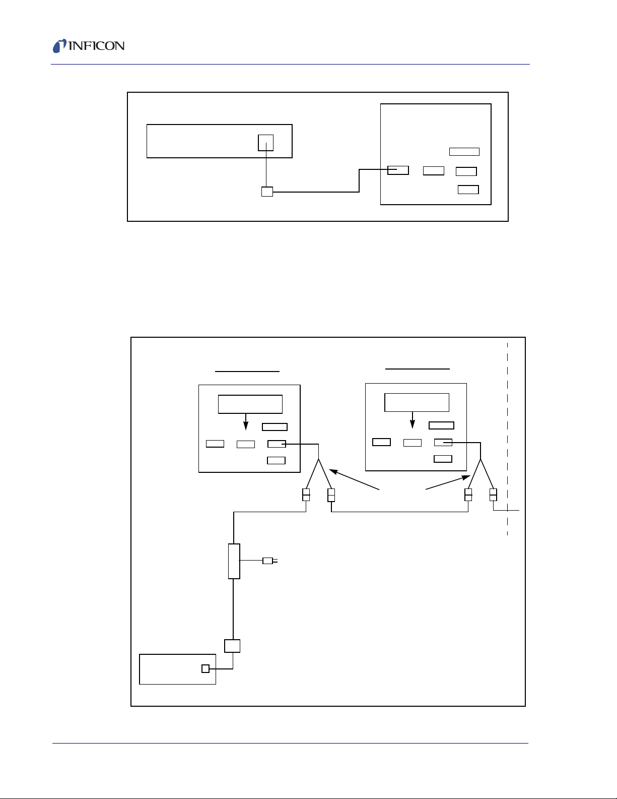
FabGuard Explorer Operating Manual
Host Computer
911-451-P1
USB/RS-232 Adapter
RS232
Aux I/O
CNFG
RS485
Power
600-1001-P#
RS-232 Interface Cable
Transpector #1
Transpector #2
Address 1
SW 8 - Off
RS232
CNFG
Aux I/O
RS485
Power
Address 1
SW 8 - Off
RS232
CNFG
Aux I/O
RS485
Power
(Male)
(Female)
(Male)
(Female)
RS-485 "Y" Cable
911-040-G#
RS-485 Interface Cable Kit
911-040-G#
RS-485 Interface Cable Kit
AC Input
90 - 260 V(ac)
600-1118-P1
TCA Cable
911-451-P1
USB/232 Adapter
USB
Port
Host Computer
TCA
Adapter
Figure 1-1 RS-232 Connection
1.6.1.3.2 Multiple Sensor Version (RS485 Plus TCA485 Adapter)
Attach the male DB9 connector on the USB to RS-232 Standard Adapter Cable to
the female DB9 connector on the Transpector TCA485 Cable (IPN 600-1118-P1).
Connect the USB connector on the USB to RS-232 Standard Adapter Cable to the
computer. See Figure 1-2 for the rest of the RS-485 cabling.
Figure 1-2 RS-485 Installation
1 - 8
IPN 074-528-P1A
Page 25

1.6.2 RFS100 Communications
The INFICON RFS100 sensor uses RS-232 Communications with a Baud Rate of
19.2K (19,200).
For more information about RFS100 Communications, please see the RFS100
Operating Manual (IPN 074-423).
1.6.3 Quantus Communications
The INFICON Quantus sensor uses an Ethernet (TCP/IP Modbus) connection for
communication to FabGuard Explorer.
For more information about Quantus Communications, please see the Quantus
Operating Manual (IPN 074-510).
1.6.4 Stiletto Communications
The INFICON Stiletto particle detector (SPD) uses an Ethernet (TCP/IP Modbus)
connection for communication to FabGuard Explorer
FabGuard Explorer Operating Manual
For more information about Stiletto Communications, please see the Stiletto
Operating Manual (IPN 074-374).
1.7 How To Install FabGuard Explorer
Install FabGuard Explorer from within Windows as follows:
NOTE: This description assumes the CD/DVD ROM drive is drive "d". If it is not
"d", substitute the appropriate drive letter.
1 Insert the CD in the CD/DVD ROM Drive
2 Select Start >> Run... to display the Run dialog.
3 In the Open field, type d:\FabGuard_EX_Single_Installer.exe
for the Single Sensor version of FabGuard Explorer or type
IPN 074-528-P1A
d:\FabGuard_EX_Multi_Installer.exe for the Multi-Sensor
version of FabGuard Explorer.
4 Select OK.
1 - 9
Page 26
FabGuard Explorer Operating Manual
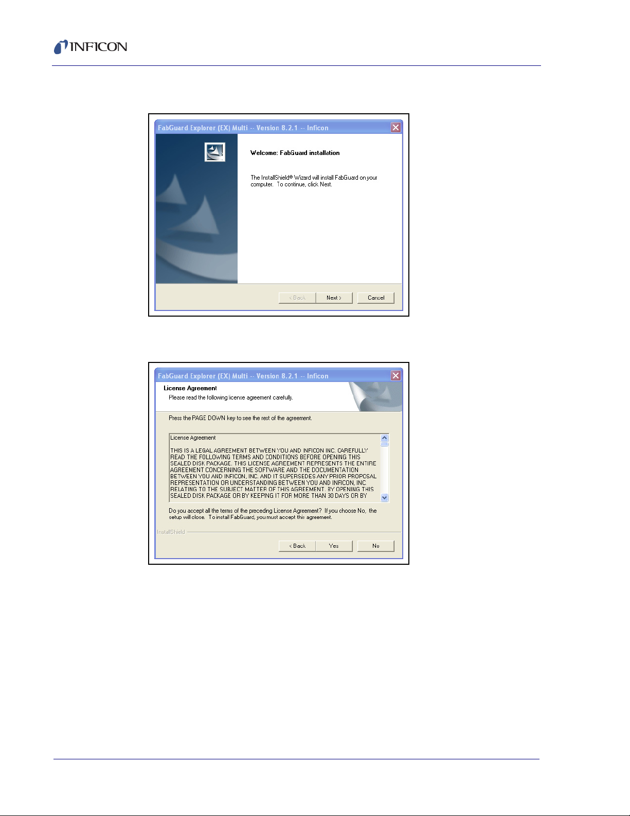
5 At the following prompt, click Next > to continue (see Figure 1-3 on page 1-10).
Figure 1-3 Initial Installation
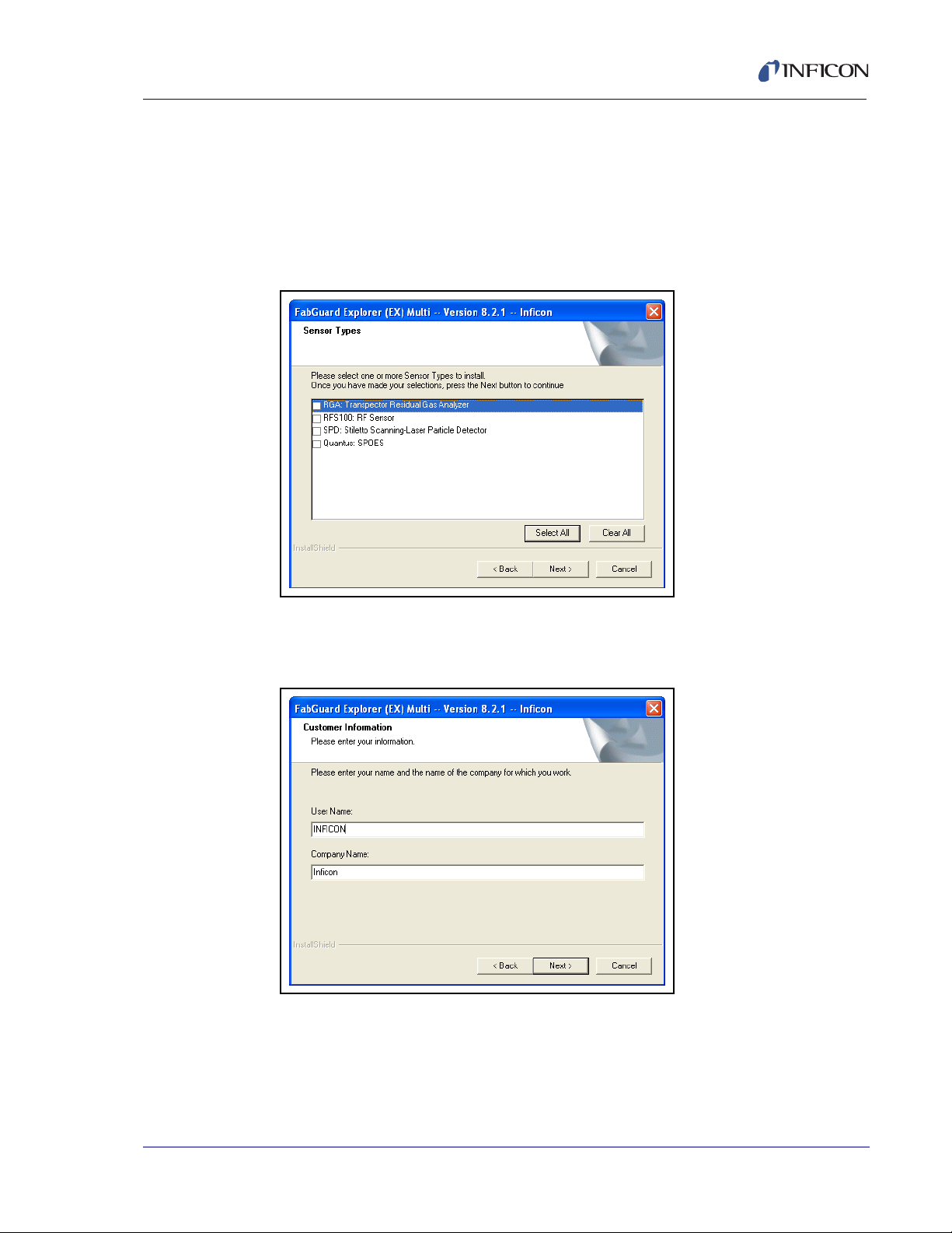
6 Read the License Agreement and choose Yes to continue (see Figure 1-4).
Figure 1-4 License Agreement
1 - 10
IPN 074-528-P1A
Page 27
FabGuard Explorer Operating Manual
7 Choose what sensor drivers to install. Then click Next > to continue (see Figure
1-5 on page 1-11).
NOTE: ONLY install drivers for sensors that are currently installed on the
system. The additional sensor drivers are available for install through
the FabGuard installation CD at any time if a new sensor type is
installed.
Figure 1-5 Sensor Type Selection
8 Enter a user name and company. Then click Next > to continue (see Figure
1-6).
Figure 1-6 User Name and Company
IPN 074-528-P1A
9 Select Start >> Run... to display the Run dialog.
10 In the Open field, type d:\FabGuardHelp_Installer.exe
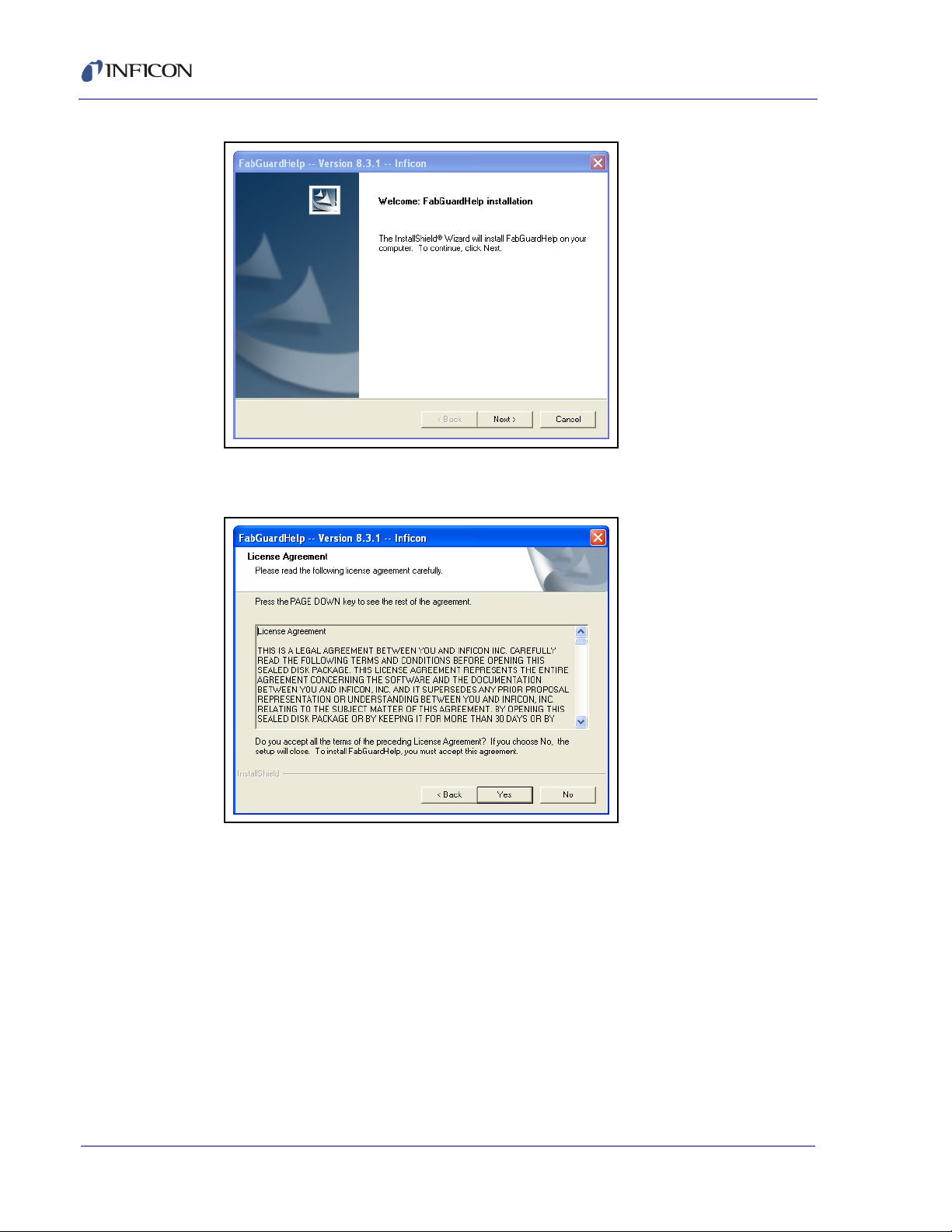
At the following prompt, click Next > to continue (see Figure 1-7)
11
1 - 11
Page 28
FabGuard Explorer Operating Manual
Figure 1-7 FabGuard Help Installation
12 Read the License Agreement and select Yes to continue (see Figure 1-8).
Figure 1-8 Help License Agreement
1 - 12
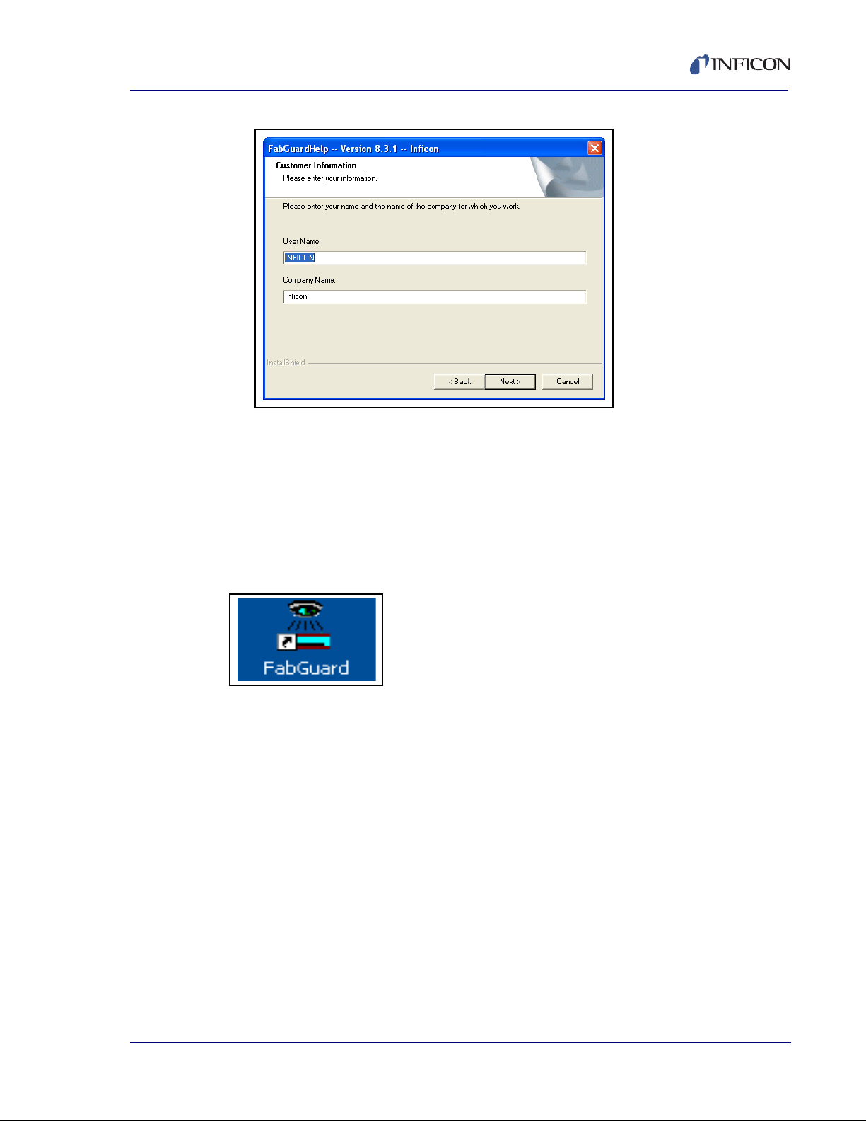
13 Enter a user name and company then click Next > to continue (see Figure 1-9
on page 1-13)
IPN 074-528-P1A
Page 29
FabGuard Explorer Operating Manual
Figure 1-9 Customer Information
14 When installation is complete, put the original CD in a safe storage area.
1.8 How To Start FabGuard Explorer
There are several different ways to start FabGuard Explorer. The easiest way is to
double-click on the icon that FabGuard Explorer installed on the desktop (see
Figure 1-10).
Figure 1-10 FabGuard Icon
The first time FabGuard Explorer is run on a computer, it will start at the main
screen with a prompt to setup connection to the installed sensors. See Chapter 3
for information on how to configure the communications interface, individual
IPN 074-528-P1A
sensors, and user preferences on the system.
1 - 13
Page 30

FabGuard Explorer Operating Manual
1.9 Where to Go From Here
This Operating Manual is intended to make the process of setting up, installing and
using FabGuard Explorer a pleasurable and trouble-free experience. Please, take
a few moments to look through it and become familiar with its contents.
The information in this manual is organized into the following chapters:
Chapter 1, Getting Started
An introduction to the FabGuard Explorer application, provides instructions on
how to install and run FabGuard Explorer and explains how to use this
Operating Manual.
Chapter 2, How the Software Works
A discussion of the underlying principles of FabGuard Explorer’s operation and
some general descriptions of the FabGuard Explorer user Interface.
Chapter 3, Setup and Configuration
A description of how to set up the software for installation and customize it to
the user’s preferences.
Chapter 4, Data Acquisition
Discusses the methods of data acquisition inside of FabGuard Explorer.
Chapter 5, Visualization
Discusses the visualization functions inside of FabGuard Explorer.
Chapter 6, Maintenance
Explains the maintenance functions inside of FabGuard Explorer. This chapter
helps keep the operating sensors in peak condition.
Chapter 7, Alarms
Introduces and explains the alarm functionality present in FabGuard Explorer.
Chapter 8, When Things Go Wrong
Includes discussions about errors in FabGuard Explorer.
IPN 074-528-P1A
1 - 14
Page 31

2.1 Overview
FabGuard Explorer is a standard 32-bit Windows application using many of the
standard user interface features with which users should be familiar from other
Windows applications. The use of cascading menus, tool bars, and context
sensitive menus common to many Windows applications makes FabGuard
Explorer easy to learn and easy to use. This chapter gives the user an introduction
to the basic layout of the FabGuard Explorer program and explains how it works.
The individual functions are described in greater detail in subsequent chapters.
2.2 Navigating FabGuard Explorer
The FabGuard Explorer screen consists of several components which are unique
to each mode, but there are some underlying features that are always present.
These features include Colors, Tabs, Menus and Buttons. Colors are always used
for informational purpose regarding the status of an instrument or function while
Tabs, Menus, and Buttons are used for navigation and functionality (see Figure 2-1
on page 2-2).
FabGuard Explorer Operating Manual
Chapter 2
How the Software Works
There are numerous ways to access the functionality of FabGuard Explorer. The
user interface was designed to put the most frequently used functions in easily
accessible places on the screen and to put less frequently used functions in less
obtrusive places. To accomplish this, most of the functionality can be accessed via
the cascading menus. The most frequently used commands are duplicated in
button form or can often be reached via right-clicking throughout the program.
IPN 074-528-P1A
2 - 1
Page 32

FabGuard Explorer Operating Manual
Buttons
Colors
Tabs
Figure 2-1 Screen Layout
2 - 2
IPN 074-528-P1A
Page 33

2.2.1 Colors
FabGuard Explorer Operating Manual
There are colors present throughout FabGuard Explorer (see Table 2-1). These
colors represent status and alarms primarily. On several screens, different colors
represent the status of the instrument or parts of the instrument (emission, electron
multiplier, etc.). On other screens represent the severity of alarms present on an
instrument. More information on alarms is present in Chapter 7.
Table 2-1 System Status Colors
Color Status
Green On or Online
Red Error, Alarm or Went Offline (from Online)
Dark Grey Off
Light Grey Not Available
Yellow Waiting, Maintenance Required, or Moderate Warning
Dark Blue Offline or Informational Alarm
2.2.2 Tabs
FabGuard Explorer utilizes modern tabular interfaces to navigate through the
software. Each screen of the software is represented by a tab which can be
accessed from any other screen, as shown in Figure 2-2.
Figure 2-2 Tabs in FabGuard Explorer
Tabs are also found inside of many of the menus in FabGuard Explorer (see Figure
2-3). These tabs help link together appropriate features without cluttering the
screen.
IPN 074-528-P1A
Figure 2-3 Tabs Inside of the Configure Function
2 - 3
Page 34

FabGuard Explorer Operating Manual
2.2.3 Menus
FabGuard Explorer utilizes the look of the traditional Windows GUI, but provides
specific menus for FabGuard Explorer. The different menus are User, Screens,
Run, Recipe, Acquisition, Configure, and Help. These cascading menus are
quick ways to reach a multitude of different functions and screens. See Figure 2-4.
Figure 2-4 FabGuard Explorer Menu Bar
2.2.3.1 User Menu
The User menu, shown in Figure 2-5, allows the user to log in for advanced access.
Figure 2-5 User Menu
2.2.3.2 Screens Menu
The Screens menu, see Figure 2-6, is a dropdown that acts as an alternative to
the Tab functions of the GUI, giving links to all five main screens.
Figure 2-6 Screens Menu
IPN 074-528-P1A
2 - 4
Page 35

2.2.3.3 Run Menu
The Run menu, see Figure 2-7, includes links to:
Figure 2-7 Run Menu
FabGuard Explorer Operating Manual
Load Run*... which allows the user to load any previously acquired Run.
IPN 074-528-P1A
Load last Run Acquired by the Sensor loads the last acquired data by the
sensor.
Shortcuts to the last five loaded Runs.
Save Run and Save Run As... both save the current Run if any changes have
been made.
Import and Export for importing/exporting data in different formats.
Clear Run, removes the current run from memory (doesn’t delete it from disk).
Clear Run and Delete it from Disk removes the current in memory run and
deletes it from the disk.
2 - 5
Page 36

FabGuard Explorer Operating Manual
Clear All Runs in Memory removes all of the runs currently loaded in the
program (doesn’t delete them from the disk).
Bin Create *... creates Bins from a loaded Run.
View Run ... opens the current run in a separate viewing window.
Run Info *... links to the Run Summary which is discussed in Chapter 4.
Print Run Info prints the Run Summary.
Run Comment *... allows the user to write a comment about the Run.
Run’s Sensor Parameters ... pulls up the sensor parameters for the Run.
Tag Scan allows the user to Tag a scan as background, normal or User for
subtraction. This is discussed in more detail in Chapter 5.
Scan Create From Bins allows the user to create a scan based on the Bins
that were collected.
Multi Run Viewer *... switches to the Multi Run Viewer which allows for
multiple scans to be compared on the same axes.
Create Recipe from Run ... allows for one click recipe creation based on the
loaded Run.
Chemistry Library enables the user to compare their Run to a Chemistry
Library. This is discussed in more detail in Chapter 5.
2.2.3.4 Recipe Menu
The Recipe menu, see Figure 2-8, has links to:
Figure 2-8 Recipe Menu
Create from Scratch ... which creates a recipe without any preset values.
Create from Run ... which generates a recipe from a successful data
collection.
Edit ... which allows the user to edit a previously created recipe.
IPN 074-528-P1A
2 - 6
Recent File which is normally populated with links to the most recently used
recipes.
Page 37

2.2.3.5 Acquisition Menu
The Acquisition menu, see Figure 2-9, has links to:
Figure 2-9 Acquisition Menu
Sensor: Configuration Monitor Start * opens the Configuration Monitor
mode for the selected sensor.
Sensor: Configuration Monitor Stop * stops the Configuration Monitor for
the selected sensor.
FabGuard Explorer Operating Manual
Sensor: Maintenance Acquisition Start allows the user to select one of five
different Maintenance Acquisition Templates which can be setup for one
click access. Hovering the cursor over this option produces the menu seen in
Figure 2-10.
Figure 2-10 Maintenance Acquisition Start Options
IPN 074-528-P1A
Sensor: Maintenance Acquisition Stop * stops any running Maintenance
Acquisitions.
Sensor: Manual Acquisition Start allows the user to start collecting data
using several different acquisition techniques. Hovering the cursor on this
option produces the menu seen in Figure 2-11. For more information on the
different acquisition methods, see Chapter 4, Data Acquisition.
Figure 2-11 Manual Acquisition Start Options
2 - 7
Page 38

FabGuard Explorer Operating Manual
Sensor: Manual Acquisition Stop * stops the manual acquisition that is
currently running.
Sensor: Acquisition Bin Defaults ... allows the user to set the default signal
bins that FabGuard Explorer uses for a Quick Manual Acquisition scan.
Sensor: Acquisition Control Defaults ... allows the user to set the default
acquisition controls that FabGuard Explorer uses for a Quick Manual
Acquisition scan.
2.2.3.6 Maintenance Menu
The Maintenance menu, see Figure 2-12, includes links to:
Figure 2-12 Maintenance Menu
2 - 8
Maintenance * which opens the Maintenance GUI.
Leak Check * which starts Leak Check mode using the selected sensor.
Leak Check (inlet open) * which starts Leak Check mode with an inlet open
(only for CPM units).
Vacuum Diagnostics * which starts Vacuum Diagnostics mode for the
selected sensor.
Maintenance (#) Start which allows the user to start one of five different
Maintenance Run Templates.
Maintenance Stop * stops the currently running Maintenance Run Template.
Configure Maintenance Run Templates ... which allows the user to configure
the Maintenance Run Templates.
More detail on all of these functions is featured in Chapter 6.
IPN 074-528-P1A
Page 39

2.2.3.7 Configure Menu
The Configure menu, see Figure 2-13, includes links to:
Figure 2-13 Configure Menu
Main Screen (Tool) ... which allows the user to configure the Main screen.
FabGuard Explorer Operating Manual
Sensor ... which allows the user to configure the selected sensor.
Sensor Bring On Line (Reset) brings an off line sensor on line.
Sensor Bring Off Line brings an on line sensor off line.
Reset All Sensors resets the connections for all installed sensors.
I/O Connections (Sensors) ... opens the I/O Connections menu.
Alarms ... opens the Alarms configuration menu.
Preferences ... opens the User Preferences menu.
Demo is only available to users with advanced access and allows Ghost
Sensors to be added.
IPN 074-528-P1A
2 - 9
Page 40

FabGuard Explorer Operating Manual
2.2.3.8 Help Menu
The Help menu, see Figure 2-14, has links to:
Figure 2-14 Help Menu
About the Program ... opens an About the Program splash screen with
FabGuard Help *... opens the electronic copy of the FabGuard Explorer
Current Status Log ... displays the current status of FabGuard Explorer in a
version information.
manual.
new internet browser window.
2 - 10
IPN 074-528-P1A
Page 41

2.2.3.9 Context Sensitive Menus
Context sensitive menus, see Figure 2-15, are pop-up menus which contain
commands most likely to be used in a specific situation. They are primarily
associated with right-click functionality. If the right mouse button is clicked, a menu
will appear near the cursor. The contents of this menu depend on what is being
displayed and where on the screen the cursor is positioned. This right-click menu
will often provide quick access to a desired function, so some experimentation is
required.
Figure 2-15 Sensor Right-Click Menu
FabGuard Explorer Operating Manual
IPN 074-528-P1A
2 - 11
Page 42

FabGuard Explorer Operating Manual
2.2.4 Buttons
Buttons represent the last feature of screen layout seen on every screen. These
buttons either have one-click functionality, wherein the user left-clicks on the button
and the function begins, see Figure 2-16, or the buttons will sometimes open a new
cascading menu where another selection must be made, see Figure 2-17.
Figure 2-16 Button Examples
Figure 2-17 Button Cascading Menu Example
IPN 074-528-P1A
2 - 12
Page 43

2.3 FabGuard Explorer Screens
Alarm Display Preferences
Current Alarms
Alarm Details
The FabGuard Explorer GUI utilizes different screens for much of the software’s
different functionality. It is very easy to navigate from screen to screen using the
tabs described in the previous section. This section will act as an introduction to the
various screens and begin the discussion of their respective functions. For further
discussion, see the various chapters that are referenced within.
2.3.1 Alarm
The Alarm screen, see Figure 2-18, shows any Informational, Moderate
Warning and Critical alarms present in the installed sensors. From the Alarm
screen, alarms can be viewed, cleared and deleted. For a more in depth discussion
of alarms, see Chapter 7.
Figure 2-18 The Alarm Screen
FabGuard Explorer Operating Manual
IPN 074-528-P1A
2 - 13
Page 44

FabGuard Explorer Operating Manual
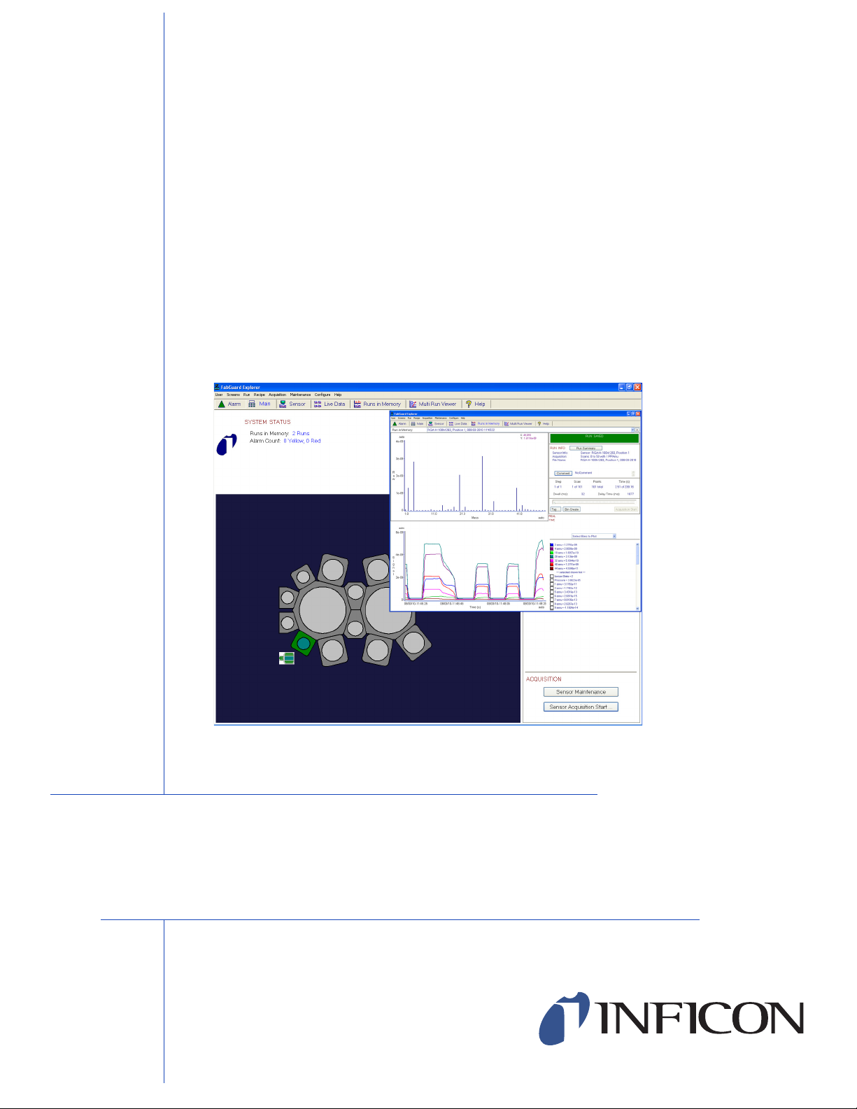
2.3.2 Main
The Main screen, see Figure 2-19, is the first screen that is shown whenever
FabGuard Explorer is started. The Main screen includes such features as: a
customizable tool diagram; status colored representations of the installed sensors;
a synopsis of alarms and number of runs in memory; sensor information such as
name, type and serial number; the status of the emission and electron multiplier for
each installed RGA; and buttons for data acquisition and sensor maintenance. For
a more in depth discussion of the functionality, see Chapter 3 and Chapter 4.
The Main screen is important because this is where the active sensor is chosen.
In situations where there are more than one sensor installed on a system, only one
sensor can be the active sensor at any given time. The active sensor is the one
represented by the status shown on the right side of the Main screen and the
entirety of the Sensor screen. To make a sensor active, left-click once on the
sensor. The graphical representation of the sensor will change to now include a
white background around the icon. If a sensor is not made active on this screen,
clicking on the Sensor screen automatically chooses a random sensor.
Figure 2-19 The Main Screen
2 - 14
IPN 074-528-P1A
Page 45

2.3.3 Sensor
The Sensor screen, see Figure 2-20, is reliant on the type of installed sensor. In
the case where multiple sensors are installed on one system, the Sensor screen
will control the active sensor. This screen includes the ability to configure the
installed sensor via the Configure button near the bottom of the screen and the
Change button on the right side of the screen. The Configuration Monitor
function then will run a scan with the sensor using the current configuration
parameters. This allows the user to see what effect the changes in configuration
will make on the acquired data. The Sensor screen also includes access to the
Maintenance menu and the capability to Tag a Scan. For a more in depth
discussion of these functions, see Chapter 3, Setup and Configuration; Chapter 4,
Data Acquisition; Chapter 5, Visualization and Chapter 6, Maintenance.
Figure 2-20 Sensor Screen
FabGuard Explorer Operating Manual
IPN 074-528-P1A
2 - 15
Page 46

FabGuard Explorer Operating Manual
2.3.4 Live Data
The Live Data screen shows up to four live data acquisition trend graphs
concurrently. If more than four sensors are installed on the system, the drop down
menus at the top of each subscreen allow for choosing sensors other than the one
showcased in the window. See Figure 2-21
Figure 2-21 Live Data Screen
2 - 16
IPN 074-528-P1A
Page 47

2.3.5 Runs In Memory
During data acquisition, a screen is shown, see Figure 2-22, which includes a
spectrum graph for each scan (can be either single points or analog) and a trend
graph for the entire run. Upon completion of the run, the data is saved and loaded
into the Runs in Memory screen. This screen allows for access to the Run
Summary, the ability to make a Comment on the data acquisition (for example,
CPM run with V2 open and no V4 bypass), the Tag function, Bin Create
functionality for bar graph acquisitions and the capability of customizing the trend
graph using the active bins on the lower right hand side of the screen. A more
detailed discussion of these functions is present in Chapter 5.
Figure 2-22 Runs in Memory
FabGuard Explorer Operating Manual
IPN 074-528-P1A
2 - 17
Page 48

FabGuard Explorer Operating Manual
2.3.6 Multi Run Viewer
The Multi Run Viewer screen, shown in Figure 2-23, allows for multiple runs to be
graphed on the same axes. There are a multitude of different options for
presentation of the data as well as customization of the bins to display in the trend
graph(s). For a more detailed discussion of this screen, see Chapter 5.
Figure 2-23 Multi Run Viewer Screen
2 - 18
IPN 074-528-P1A
Page 49

2.4 Basic Features
FabGuard Explorer provides quick and easy access to the most common functions
of a Residual Gas Analyzer (RGA). The next section describes these functions and
the method of starting the functions.
2.4.1 Data Acquisition
The primary function of an RGA control software package is data acquisition.
FabGuard Explorer offers numerous different ways to acquire data from the RGA
sensor. These include Quick Manual Acquisition, Manual Acquisition from
Scratch, Manual Acquisition from Recipe, and Manual Acquisition from Run
(a full discussion of the differences between each method is available in Chapter
4). The easiest and quickest way to access any of these functions is to right-click
the appropriate sensor on the Main screen and choose the desired data acquisition
method from the context sensitive menu.
Once FabGuard Explorer has begun acquiring data, a screen displaying the Trend
Graph and Mass Spectrum Graph is displayed. The Mass Spectrum Graph
shows each scan of the data acquisition immediately following completion of the
scan. This graph displays current as a function of mass at the time that the data
was acquired in its default setting. The Trend Graph displays the current of a
specific amu value with regards to time. Through this graph, trends of gas
concentration become apparent. The mass values that are displayed can be
customized via the bin control on the lower right-hand side of the screen.
FabGuard Explorer Operating Manual
After a run is completed, visual analysis can be done on the data or the run
parameters can be saved as a recipe with one click. For more detail see Chapter
4 and Chapter 5.
2.4.2 Leak Check
Leak Check mode is part of the Maintenance submenu inside of FabGuard
Explorer. The mode is designed to help detect and locate leaks in a vacuum
IPN 074-528-P1A
system. This mode is most easily accessed by right-clicking on the sensor of
interest at the Main screen and choosing Leak Check from the cascading menu.
The Leak Check display consists of a Trend Display showing the intensity of a
single mass peak being monitored as a function of time, a Thermometer Bar
Gauge which gives a visual indication of the current intensity and a Control Panel
which allows for alarm/warning level derivation. For more detail on Leak Check
mode, see Chapter 6.
2.4.3 Tune
The Transpector RGA is calibrated at the factory for correct mass alignment and
resolution. However, during use, certain environmental conditions can cause the
initial tune to become invalid. For this reason, it is important that regular calibration
2 - 19
Page 50

FabGuard Explorer Operating Manual
of the instrument be done to achieve optimum results. A major part of this
calibration is referred to as tuning. The Tune function is part of the Maintenance
submenu and can easily be reached via the main screen.
The Tun e mode displays a window with multiple sections around nominal mass
positions. FabGuard Explorer allows for either manual tuning or it can automatically
tune the sensor based on default requirements. For a more in depth discussion of
the Tun e function, see Chapter 6.
2.4.4 Vacuum Diagnostics
Vacuum Diagnostics is a maintenance tool used to determine the gas species
present inside of a vacuum chamber. This function takes a full scan from the RGA
and immediately determines what species are present. This function is available
from right-clicking on the appropriate sensor or in the Maintenance submenu. For
a more detailed discussion, see Chapter 6.
2.5 Screen Specific Cascading Menus
One of the features of FabGuard Explorer is the use of screen specific cascading
menus. During the discussion of cascading menus in section 2.2.3 on page 2-4, the
different menus were displayed. However, not every function is available on every
screen. FabGuard Explorer utilizes a logic based function wherein only the features
relevant to the screen are shown. Table 2-2 lists each function and their availability
on each screen.
Table 2-2 FabGuard Functions Available On Each Screen
Function
File
Advanced User Log-In
Advanced User Log-Out
Exit
Run
Load Run
Load Last Run Acquired by Sensor
Save Run
Save Run As
Import
Export
Clear Run
Clear Run and Delete it from Disk
Clear All Runs in Memory
Bin Create
View Run
Run Info
Alarm Main Sensor Live Data Runs In Memory
Screen Name
IPN 074-528-P1A
2 - 20
Page 51

FabGuard Explorer Operating Manual
Function
Print Run Info
Run Comment
Run's Sensor Parameters
Tag Scan
Scan Create from Bins
Clear Scans
Create Recipe From Run
Chemistry Library
Recipe
Create From Scratch
Create From Run
Edit
Acquisition
Sensor: Configuration Monitor Start
Sensor: Configuration Monitor Stop
Sensor: Maintenance Acquisition Start
Sensor: Maintenance Acquisition Stop
Sensor: Manual Acquisition Start
Sensor: Manual Acquisition Stop
Sensor: Acquisition Bins Default
Sensor: Acquisition Control Default
Maintenance
Maintenance Menu
Leak Check
Leak Check (inlet open)
Vacuum Diagnostics
Maintenance Run Templates
Maintenance Stop
Configure Maintenance Run Templates
Configure
Main Screen (Tool)
IPN 074-528-P1A
Sensor Bring On Line (Reset)
I/O Connections (Sensors)
Sensor
Sensor Bring Off Line
Reset All Sensors
Alarms
Preferences
Alarm Main Sensor Live Data Runs In Memory
Screen Name
2 - 21
Page 52

FabGuard Explorer Operating Manual
2.6 Opening Files in FabGuard Explorer
When asked to select a filename to open or save (for example, recalling a run or
editing a recipe), an enhanced File Open dialog, like the one in Figure 2-24, is
used. This file open dialog will look like many other Windows applications and
could look different depending on the version of Windows that is installed.
Figure 2-24 FabGuard Explorer File Open Dialog
2 - 22
IPN 074-528-P1A
Page 53

2.6.1 Importing Tware32 Files
FabGuard Explorer does allow importing of TWare32 data, however, FabGuard
Explorer cannot import TWare32’s standard .sod files. FabGuard Explorer can only
import .csv files generated via TWare32's File menu, Generate Report item.
To import a TWare32 file into FabGuard Explorer, follow these steps:
1 In TWare32, open the data file that is to be imported.
2 Click on File >> Generate Report.
3 Click on the Data Format tab.
4 Choose Commas (.csv) under Column Delimiter instead of the default Tabs
(.txt) choice. See Figure 2-25 for the proper settings.
Figure 2-25 TWare32 Data Format Tab
FabGuard Explorer Operating Manual
5 Click OK and save the file in a convenient location.
IPN 074-528-P1A
6 Open FabGuard Explorer.
7 Click on Run >> Import >> RGA: TWare32.
8 Select the file that was saved in Step 5.
2 - 23
Page 54

FabGuard Explorer Operating Manual
This page is intentionally blank.
2 - 24
IPN 074-528-P1A
Page 55

3.1 Introduction
When FabGuard Explorer is first installed on a system, there are a few parameters
that need to be set to customize it to the particular hardware configuration. In
addition, several aspects of how the program looks and acts can be customized to
individual preferences. This chapter discusses how to customize a system to the
needs of a location. This chapter will focus on Transpector RGA installation and
configuration. There will be some information on the installation and setup of
Quantus SPOES sensors, RFS100 sensors and Stiletto Particle Detectors, but for
more detailed information on the setup of any of these sensors, see their
appropriate operating manual.
3.1.1 Initial Setup
FabGuard Explorer Operating Manual
Chapter 3
Setup and Configuration
The first time FabGuard Explorer is run, the following steps should be taken to set
up the system:
1 Set up the communications ports and sensors (see section 3.2 on page 3-1).
2 Customize the Main screen (see section 3.3 on page 3-13).
3 Configure each sensor (see section 3.4 on page 3-19).
4 Configure remaining preferences (see section 3.5 on page 3-44).
3.2 Communication Setup
The communications interface is set up via the I/O Connections function which is
accessed via choosing Configure >> I/O Connections (Sensors) ... or by
IPN 074-528-P1A
3.2.1 Installation of Sensors Immediately After FabGuard Explorer is
following the prompts the first time that the program is run.
Since there are two different methods for setting up sensor and communications
ports, this section will cover both methods for each type of sensor.
Opened
This section will outline the methodology for adding a sensor to FabGuard Explorer
immediately following opening of the software.
3 - 1
Page 56

FabGuard Explorer Operating Manual
3.2.1.1 Transpector RGAs
When FabGuard Explorer is run, a prompt as seen in Figure 3-1 will open.
Figure 3-1 Transpector Connection Prompt
Click Yes at this menu to reach the next prompt. At this prompt, choose whether
there is an RS-232 or RS-485 connection between the sensor(s) and the computer
(see Figure 3-2).
Figure 3-2 RS-232 or RS-485
3 - 2
After making the selection, click OK and the Connections: Serial menu will open
where the Com Port and Baud Rate (Baud Rate only applies to RS-232
connections) are chosen. If setting up an RS-232 connection, see Figure 3-3. If
setting up an RS-485 connection, see Figure 3-4 on page 3-3.
Figure 3-3 RS-232 Connections: Serial Menu
IPN 074-528-P1A
Page 57

FabGuard Explorer Operating Manual
Figure 3-4 RS-485 Connections: Serial Menu
After clicking OK, FabGuard Explorer will automatically try to find sensors based
on the configuration that was set on the prior two screens. If a sensor is found, it
will appear as an icon on the main screen. Once this occurs, go to section 3.3, Main
Screen Setup, on page 3-13. If a sensor does not appear, recheck the connections
and the choices that were made on the previous screen. If the settings need to be
changed, follow section 3.2.1.5, Installation of Sensors Using I/O Connections, on
page 3-9.
3.2.1.2 RFS100
When FabGuard Explorer is run, a prompt as seen in Figure 3-5 will open
Figure 3-5 RFS100 Connection Prompt
IPN 074-528-P1A
Click Yes at this menu to reach the next prompt. At this prompt, 16-bit RS232
connection (see Figure 3-6 on page 3-4) needs to be selected. The RFS100 does
not use a 12-Bit RS232 connection.
3 - 3
Page 58

FabGuard Explorer Operating Manual
Figure 3-6 RFS100 Connection Type
After making the selection, click OK and the Connections: Serial menu will open
where the Com Port is chosen (see Figure 3-7).
Figure 3-7 RFS100 Connections: Serial Menu
3 - 4
After clicking OK, FabGuard Explorer will automatically try to find a sensor based
on the configuration that was set on the prior two screens. If a sensor is found, it
will appear as an icon on the main screen. Once this occurs, go to section 3.3, Main
Screen Setup, on page 3-13. If a sensor does not appear, recheck the connections
and the choices that were made on the previous screen. If the settings need to be
changed, follow section 3.2.1.5, Installation of Sensors Using I/O Connections, on
page 3-9.
IPN 074-528-P1A
Page 59

3.2.1.3 Stiletto Particle Detector
When FabGuard Explorer is run, a prompt as seen in Figure 3-8 will open.
Figure 3-8 Stiletto Connection Prompt
Click Yes at this menu to reach the next prompt. At this prompt, select OK, because
the Stiletto only supports communications through Modbus/TCP (see Figure 3-9).
Figure 3-9 Stiletto Connection Type
FabGuard Explorer Operating Manual
After clicking OK, the Connections: Modbus/TCP menu will open where the IP
address of the installed unit(s) must be entered underneath Stiletto SPD (see the
circled region in Figure 3-10 on page 3-6).
IPN 074-528-P1A
3 - 5
Page 60

FabGuard Explorer Operating Manual
Figure 3-10 Stiletto Connections: Modbus/TCP Menu
After clicking OK, FabGuard Explorer will automatically try to find sensors based
on the configuration that was set on the prior two screens. If a sensor is found, it
will appear as an icon on the main screen. Once this occurs, go to section 3.3, Main
Screen Setup, on page 3-13. If a sensor does not appear, recheck the connections
and the choices that were made on the previous screen. If the settings need to be
changed, follow section 3.2.1.5, Installation of Sensors Using I/O Connections, on
page 3-9.
3.2.1.4 Quantus SPOES
The Quantus instruments install differently than the other supported sensors. This
section will outline the different connection methods needed.
The Quantus can either be manually assigned an IP address or automatically have
one assigned by DHCP. It is recommended that the Quantus be on the same
network router switch. All Quantus IP address settings are accomplished using the
installed
Quantus IP Setup.exe located in the C:\Inficon directory.
To set the IP address for the Quantus, open the
program and proceed via the appropriate following section.
IPN 074-528-P1A
Quantus IP Setup.exe
3 - 6
Page 61

FabGuard Explorer Operating Manual
3.2.1.4.1 Automatically Assigning the Quantus an IP Address (DHCP)
Open the
Quantus IP Setup.exe and enter all zeros (0) for the network
settings as seen in Figure 3-11. Have the Quantus IP Setup program search the
network for the connected Quantus. The first time that the Quantus is setup, it will
appear with a red colored icon in the Quantus IP Setup program. This is normal and
just indicates that the Quantus has not had an IP address set on it previously. Once
located, click on it under Select a Unit and click the Set--> button. This will tell the
Quantus to generate its own unique IP address through DHCP.
NOTE: Ensure that the network that the Quantus is installed on will assign an IP
address to the Quantus. If the network is incapable of performing this, then
the IP address must be set manually (see section 3.2.1.4.2).
Figure 3-11 Quantus IP Address - DHCP
After automatically assigning the Quantus an IP address, it is critical that the IP
address of the sensor is retrieved for locating the Quantus inside of FabGuard. To
do this, have the Quantus IP Setup program search the network again by clicking
Search Again. The Quantus should now show up with an assigned IP address.
Clicking on it should bring up the NDK Settings for the unit. Write down the IP
address for retrieval later.
3.2.1.4.2 Manually Assigning the Quantus an IP Address
IPN 074-528-P1A
Open the
Quantus IP Setup.exe and enter the network information under
the NDK Settings as seen in Figure 3-12 on page 3-8. Have the Quantus IP Setup
program search the network for the Quantus. The first time that the Quantus is
setup, it will appear with a red colored icon in the Quantus IP Setup program. This
is normal and just indicates that the Quantus has not had an IP address set on it
previously. Once located, click on it under Select a Unit and click the Set--> button.
This will assign the Quantus the IP address that was entered under NDK Settings.
3 - 7
Page 62

FabGuard Explorer Operating Manual
Figure 3-12 Setting the IP Address Manually
After manually setting the IP address for the Quantus, write down the IP address
that was chosen.
3.2.1.4.3 Setting up the Quantus in FabGuard Explorer
When FabGuard Explorer is run, a prompt as seen in Figure 3-13 will open.
Figure 3-13 Quantus Connection Prompt
3 - 8
Click Yes at this menu to reach the next prompt. At this prompt, select OK, because
the Quantus only supports communications through Modbus/TCP (see Figure
3-14).
Figure 3-14 Quantus Connection Type
IPN 074-528-P1A
After clicking OK, the Connections: Modbus/TCP menu will open where the IP
address of the installed unit(s) must be entered underneath Quantus SPOES (see
the circled region in Figure 3-15).
Page 63

FabGuard Explorer Operating Manual
WARNING
Figure 3-15 Quantus Connections: Modbus/TCP Menu
After clicking OK, FabGuard Explorer will automatically try to find sensors based
on the configuration that was set on the prior two screens. If a sensor is found, it
will appear as an icon on the main screen. Once this occurs, go to section 3.3, Main
Screen Setup, on page 3-13. If a sensor does not appear, recheck the connections
and the choices that were made on the previous screen. If the settings need to be
changed, follow section 3.2.1.5.
3.2.1.5 Installation of Sensors Using I/O Connections
Using the Configure >> I/O Connections ... is rarely done for initial installations.
The primary use of this installation method is for altering the settings used in the
connections.
To begin this method of installing sensors, click on Configure >> I/O Connections
... which opens the I/O Connections Menu (see Figure 3-16).
IPN 074-528-P1A
Before setting up a new sensor via this method, stop any
data acquisitions that are currently running. After
installing, deleting, or editing any sensors, all sensors
attached to the system must be reset. Therefore, do not
collect data while using the I/O Connections Menu.
3 - 9
Page 64

FabGuard Explorer Operating Manual
Sensor Drivers Installed
On the System
Sensors Installed
On the System
Figure 3-16 I/O Communications Menu
3 - 10
The I/O Connections screen includes visual representations of the Drivers that
were installed during section 1.7, How To Install FabGuard Explorer, on page 1-9.
In the image, all four possible Sensor Drivers were installed, however, there should
only be sensor drivers installed for the sensors that are currently, physically
installed on the system. As can be seen in the image, each sensor driver has an
image of a green traffic light next to it. This means that all of the sensor drivers are
installed and working correctly.
The I/O Connections menu also includes the list of Protocol Drivers for any
sensors that were previously installed in section 3.2.1, Installation of Sensors
Immediately After FabGuard Explorer is Opened, on page 3-1. As can be seen in
this case, the sensor protocol driver has an image of a red traffic light next to it. This
means that there is no sensor currently active although one is set up. This could
be due to the sensor being removed or the sensor not being properly set up.
When first entering the I/O Communications menu, only the Add Connection
(Resets All Sensors) button will be available to click on. If a connection needs to
be added, click on the button and continue to section 3.2.1.5.1, Adding a
Connection in the I/O Connections Menu, on page 3-11.
IPN 074-528-P1A
Page 65

FabGuard Explorer Operating Manual
To edit a current sensor, click on the sensor needs editing and the Edit/Test
Connection Parameters button will become active. Click the button and continue
to section 3.2.1.5.2, Edit/Test Connection Parameters, on page 3-12).
If an extra sensor is accidentally created under the Protocol Drivers, it can be easily
deleted. Simply click on the sensor’s Protocol Driver then click on the button in the
lower right hand portion of the screen, Delete Connection (Resets All Sensors).
This is also useful for permanently removing a sensor from the system.
3.2.1.5.1 Adding a Connection in the I/O Connections Menu
After clicking the Add Connection (Resets All Sensors) button, a Connection
Type prompt will appear (see Figure 3-17). To choose the proper connection and
Communications settings, see the appropriate section outlined below:
If installing a Transpector RGA, see section 3.2.1.1, Transpector RGAs, on
page 3-2.
If installing an RFS100 sensor, see section 3.2.1.2, RFS100, on page 3-3.
If installing a Stiletto (SPD) sensor, see section 3.2.1.3, Stiletto Particle
Detector, on page 3-5.
If installing a Quantus SPOES sensor, see section 3.2.1.4, Quantus SPOES,
on page 3-6.
Choose the proper connection type and click OK.
Figure 3-17 I/O Communications Connection Type
IPN 074-528-P1A
The next prompt selects the connection type. Follow the instructions outlined in the
appropriate section (see the above list).
After selecting the proper connection settings, a new prompt will open with the
message seen in Figure 3-18. This prompt shows that all of the sensors attached
to the system will be reset upon exit so that the new sensor(s) that were set up can
be activated.
3 - 11
Page 66

FabGuard Explorer Operating Manual
Figure 3-18 Changes to Connections Prompt
After clicking OK on this prompt, the program will return to the main I/O
Connections menu wherein a new protocol driver for the sensor that was just
installed will be displayed. Click the Close button to exit the menu and reset the
sensors. The program will go back to the Main screen where a graphical
representation of the sensor should have been added. If the sensor does not show
up, the connection settings/parameters will need to be edited (see section
3.2.1.5.2).
3.2.1.5.2 Edit/Test Connection Parameters
If the installed sensor does not show up on the Main screen or has a Red Traffic
light icon next to its Protocol Driver on the I/O Connections menu after following
the steps in either section 3.2.1, Installation of Sensors Immediately After
FabGuard Explorer is Opened, on page 3-1 or section 3.2.1.5, Installation of
Sensors Using I/O Connections, on page 3-9, the connection parameters need to
be edited and tested. To do this, click on the sensor Protocol Driver that is to be
changed and the Edit/Test Parameters button at the bottom of the menu will
become clickable. Click this button to be prompted to alter the connection
parameters for the sensor in question. For information on the proper settings, see
section 3.2.1, Installation of Sensors Immediately After FabGuard Explorer is
Opened, on page 3-1 and the sensor’s respective operating manual.
3 - 12
IPN 074-528-P1A
Page 67

3.3 Main Screen Setup
System Status
Sensor Status
Acquisition Control
Transpector
RGAs
Stiletto
RFS100
Quantus
The Main Screen is the first screen displayed when FabGuard Explorer is started.
It can also be displayed at any time by clicking on the Main tab or by selecting
Screens >> Main *.
The Main Screen consists of a Tool Diagram, Sensor Icons, Sensor Status,
System Status and Acquisition Control buttons. See Figure 3-19 for a diagram
of the Main Screen and the location of the different features.
Figure 3-19 Main Screen Layout
FabGuard Explorer Operating Manual
IPN 074-528-P1A
The default Tool Diagram is called Generic: Freehand, Sensor-Only. This is the
background that is seen in Figure 3-19. In this Tool Diagram, Sensor Icons are
the only things displayed aside from a blue background. To change the Tool
Diagram, see the next section.
3 - 13
Page 68

FabGuard Explorer Operating Manual
3.3.1 Tool Diagrams
As stated above, the default Tool Diagram is Generic: Freehand, Sensor-Only.
FabGuard Explorer allows for choosing a Tool Diagram that more closely matches
the tool on which the sensor(s) is/are installed. To change the Tool Diagram, right
click on the main screen (make sure that the cursor is not on any installed sensors)
and choose Main Screen Configure (see Figure 3-20).
Figure 3-20 Main Screen Right Click
Clicking on Main Screen Configure opens the Main Screen Configuration Menu
(see Figure 3-21 on page 3-15). This menu allows for changing the Tool Dia g ram,
arranging sensors, naming/describing the tool and (for the Generic Freehand tool)
adding/removing a background image (see section 3.3.2, Customizable
Background, on page 3-18).
FabGuard Explorer comes pre-installed with diagrams of 85 popular Tools (see
Figure 3-23 on page 3-17). Each one of these diagrams allows for sensor
placement that accurately reflects the actual physical placement of the sensor on
the physical tool. This simplifies tracking of the sensor to the actual chamber of the
tool as well as serving as a reminder of where the sensor is installed.
If a tool is not represented by the 85 different diagrams that are pre-installed,
FabGuard Explorer also offers 8 generic tools which allow for sensor placement to
generic chambers that may not be indicative of an actual system. If the generic
diagrams are unsatisfactory, FabGuard Explorer allows for uploading of a custom
.bmp image file. See section 3.3.2, Customizable Background, on page 3-18.
To choose a Tool Diagram, click on the scrollable menu next to Tool Type. After
locating the tool of choice, simply click on it, and FabGuard Explorer will generate
a diagram of the tool with the installed sensor(s) placed in chamber(s) that are
logically chosen, but might not represent the true tool installation. Next, drag each
sensor to its actual location on the physical tool (for example, if a Transpector CPM
is installed on chamber 1 of the tool, drag the icon representing the CPM to
chamber 1 on the Tool Diagram).
NOTE: Each Tool Diagram is customizable as well. If there are certain chambers
that are not installed on the specific tool, then uncheck them on the right
side of the Main Screen Configuration screen (see Figure 3-22 on page
3-16). Any chambers that are unchecked will be removed from the Tool
Diagram.
IPN 074-528-P1A
3 - 14
Page 69

Click OK and FabGuard Explorer will generate the Tool Diagram with proper
sensor placement on the Main Screen.
Figure 3-21 Main Screen Configuration Menu
FabGuard Explorer Operating Manual
IPN 074-528-P1A
3 - 15
Page 70

FabGuard Explorer Operating Manual
Figure 3-22 Selectable Chambers
3 - 16
IPN 074-528-P1A
Page 71

Figure 3-23 List of All Tool Diagrams
FabGuard Explorer Operating Manual
IPN 074-528-P1A
3 - 17
Page 72

FabGuard Explorer Operating Manual
3.3.2 Customizable Background
If none of the Tool Diagrams discussed in the previous section are appropriate,
choose the default Generic: Freehand, Sensor-Only tool which allows a
Customizable Background. The Customizable Background can be any .bmp
file, but it is recommended for it to have a size of 905x680 pixels (the size of the
Main Screen background). If an image is not 905x680 pixels, FabGuard Explorer
can either stretch the image to fit the background or place it in the upper-left corner.
Adding a customized background is simple.
1 On the Main Screen Configuration menu, choose the Generic: Freehand,
Sensor-Only tool from the drop-down list.
2 Click on the Set Background Image button on the right side of the screen.
Figure 3-24 Set Background Image Button
3 Select the appropriate .bmp image file through the file open dialog.
4 Click Open and FabGuard Explorer will draw the .bmp in the Main Screen
background.
5 To stretch the image to cover the entire background, click on the box next to
Stretch Background Image.
Figure 3-25 Stretch Background Image
6 Drag the sensors to their proper locations on the .bmp.
7 When satisfied with the image, click the OK button at the bottom of the menu.
8 If the image is unsatisfactory, click the Remove Background Image button on
the right side of the screen and repeat steps 2-6 until satisfied.
Figure 3-26 Remove Background Image Button
IPN 074-528-P1A
3 - 18
Page 73

FabGuard Explorer Operating Manual
WARNING
3.4 Sensor Configuration and Setup
Proper sensor configuration is essential for accurate data acquisition. This section
will go over the various sensors and operating parameters which can be altered
inside of the configuration menu.
3.4.1 RGA Configuration
RGAs have the most data parameters that can be configured. In order to reach the
Sensor Configuration menu, on the Main screen, right-click on the sensor to
configure and choose Sensor Configure from the menu. The Sensor
Configuration menu can also be reached by clicking on the Configure button on
the right side of the Sensor screen or by selecting Configure >> Sensor.
The alteration of parameters inside of the RGA
Configuration menu can adversely affect a sensor’s
performance. Before altering anything inside of the RGA
Configuration Menu, ensure that you are fully aware of
what you are changing. Failure to do so could lead to
sensor malfunction.
Save the configuration of the sensor before altering any of the parameters. To save
the configuration, click on the Save button at the bottom of the menu. If after
altering the configuration it is desired to load an older configuration, click on the
Load button. It is a good idea to print the configuration in case the configuration file
is deleted. To do so, click on the Print button at the bottom of the screen.
Figure 3-27 Load/Save/Print Buttons
IPN 074-528-P1A
3.4.1.1 Ionizer and Detector Tab
This tab configures the Ion Source and the Detector in the RGA. Many of the
parameters that can be altered in this tab are integral for the proper performance
of the RGA. Before altering any of the parameters, ensure that the functionality of
the parameter is understood.
3 - 19
Page 74

FabGuard Explorer Operating Manual
Figure 3-28 RGA Configuration — Ionizer and Detector
3 - 20
IPN 074-528-P1A
Page 75

3.4.1.1.1 Signal Units and References
These parameters influence data collection and interpretation.
Internal Data Units
Figure 3-29 Internal Data Units
The units used when the data arrives from the sensor. Although it is a
drop-down menu, the only choice is Raw (amps).
Reference Signal for ppm
Figure 3-30 Reference Signal for ppm
Refers to the signal that FabGuard Explorer uses to normalize the data for ppm
output. It can be set to use the standard Internal Total Pressure or it can be
set to an external input if a pressure gauge is installed with the External I/O.
FabGuard Explorer Operating Manual
3.4.1.1.2 What State to Leave the Sensor
These parameters tell FabGuard Explorer how to set the RGA upon the start of the
program, the end of a data acquisition and the exit of the program.
Figure 3-31 What State to Leave the Sensor
Emission
IPN 074-528-P1A
Refers to the status of the filament. If the filament is on, then emission is on.
Multiplier
Refers to the status of the electron multiplier. If the RGA does not include an
electron multiplier, this parameter will be greyed out.
After FabGuard Start
Refers to starting the FabGuard Explorer program. There are two settings: On
or Off. If set to On, the function will start immediately after FabGuard Explorer
opens. If set to Off, the function will not turn on when the program starts. It is
usually a good idea to have these set to Off in case the program is started when
the sensor is under non-ideal vacuum conditions.
3 - 21
Page 76

FabGuard Explorer Operating Manual
After End of Acquisition
Refers to the time immediately following an acquisition. When collecting data,
one of the parameters that can be set is whether to leave the EM/Filament on
after data is acquired. This is useful if another data collection is intended to
begin immediately following the previous one. The default setting for the EM
and Filament is Current. This means that the two functions will follow the
parameter set inside of the recipe and will remain either on or off after the data
acquisition. The functions can also be set to either On or Off after data
collection. If either On or Off is selected, this will override the parameters inside
of the data acquisition. This is useful if it is known that immediately following a
data acquisition, the sensors are exposed to a high pressure that could damage
the filament or EM. This way, if someone accidentally sets the filament/EM to
be On after data acquisition, the program would override that and set them to
Off.
After FabGuard Exit
Refers to exiting the FabGuard Explorer program. There are two settings: On
or Off. If set to On, the function will either turn on or stay on when FabGuard
Explorer closes. If set to Off, the function will either stay off or turn off when the
program closes. It is usually a good idea to have these set to Off in case the
sensors are exposed to non-ideal pressures while the program is closed.
3.4.1.1.3 Settings
The settings parameters are the operating parameters for the sensor. They include
Emission Current, Electron Energy, Focus, Rod Polarity, Ion Energy,
Multiplier and RF Operating Frequency.
Emission (
A)
Figure 3-32 Emission
The Emission Current is the current passed through the filament to generate
electrons, which collide with gas molecules to form ions.
The normal Emission Current for a High Performance or Compact sensor is
2000
A and for the XPR is 400 A for the High Emission mode and 200 A
for the Low Emission mode. Reducing the Emission Current decreases the
sensor output, but may reduce space-charge effects in the ion source at high
pressures.
CPM and XPR sensors have a selectable Low Emission mode which operates
at 200
of trace level impurities. Other instruments have this parameter disabled.
A to reduce background gas desorption which interferes with detection
IPN 074-528-P1A
3 - 22
Page 77

FabGuard Explorer Operating Manual
CAUTION
Electron Energy
Figure 3-33 Electron Energy
The energy with which an electron will strike a molecule and fragment it.
Changing the Electron Energy affects the relative quantity of doubly-charged
and fragment ions in the spectrum.
The normal Electron Energy for High Performance and
Compact sensors is 102 eV. Due to the electron optics in
the open ion source, this voltage should not be changed.
These sensors are subject to emission saturation at low
energy and the filaments will be damaged by such
operation.
For CPM and XPR sensors, the normal Electron Energy is 70 eV. A selectable
low ionization energy mode provides 40 eV of Electron Energy to s u pp res s th e
2+
formation of the Ar
vapor. If the Emission Current is reduced to 200
ions which interfere with detection of trace levels of water
A, the Electron Energy
may safely be reduced to 10 eV for CPM sensors and 40 eV for XPR sensors.
Focus (V)
Figure 3-34 Focus
The voltage used to accelerate ions out of the ion source. Adjustment of this
parameter will affect peak shape. The voltage range is 0 to 100 V. For High
IPN 074-528-P1A
Performance or Compact sensors, the normal Focus Voltage is 27 V. For the
XPR, the normal Focus Voltage is 10 V. For CPM sensors, the normal Focus
Voltage is 40 V.
Rod Polarity
Figure 3-35 Rod Polarity
The polarity of the quadrupoles. Rod Polarity can either be Normal or
Reversed. Changing the Rod Polarity may, in some cases, improve the peak
shape. The sensor’s Rod Polarity is calibrated to its optimum value at the
factory and should not be changed from the factory setting unless absolutely
necessary.
3 - 23
Page 78

FabGuard Explorer Operating Manual
CAUTION
CAUTION
Ion Energy (meV)
Figure 3-36 Ion Energy
The kinetic energy, along the axis of the quadrupole, of the ions as they pass
through the mass filter.
Normal Ion Energy is 10000 meV for a High Performance or Compact sensor
and 8000 meV for XPR sensors, within a range of 5000 to 15000 meV. For a
CPM sensor, the normal value is 6000 meV. Changing the Ion Energy may
improve peak shape, but may also result in a decrease in sensitivity.
The sensor’s ion energy is calibrated to its optimum
value at the factory and should not be changed from the
factory setting unless absolutely necessary.
Multiplier (V)
Figure 3-37 Multiplier
Sets the voltage of the Electron Multiplier. Normally this value is set via the
EM Calibration function (see Chapter 6), however, a value can be entered
directly here.
RF Operating Frequency
Figure 3-38 RF Operating Frequency
The RF Operating Frequency cannot be set on this screen. FabGuard
Explorer includes a Reset RF Frequency function inside of the Maintenance
submenu (see Chapter 6).
Focus, Rod Polarity and Ion Energy are set by the factory
for optimum performance. It is NOT RECOMMENDED that
the user alter these settings.
IPN 074-528-P1A
3 - 24
Page 79

3.4.1.2 RGA Configuration — Correction Tab
The Correction tab of the RGA Configuration Menu provides parameters used
to correct data during data acquisition.
Figure 3-39 RGA Configuration — Correction Tab
FabGuard Explorer Operating Manual
3.4.1.2.1 Over-Pressure Error Recovery (Hardware)
IPN 074-528-P1A
These settings control how the RGA behaves in case of an overpressure in the
process which could damage the filament and electron multiplier.
Use Internal Overpressure Protection
Figure 3-40 Use Internal Overpressure Protection
The RGA has the capability to estimate internal pressure based on current at
the ion source. If this internal pressure becomes too high (>5E-4 Torr for High
Performance/Compact sensors, >20 mTorr for XPR3 sensors, etc.) the filament
and electron multiplier can be damaged. Therefore, this setting uses the
3 - 25
Page 80

FabGuard Explorer Operating Manual
internal pressure estimation to turn off the Emission and EM if the pressure
becomes too high. This protection is superseded by Aux I/O if the Aux I/O is a
pressure gauge. Any auxiliary pressure gauge will provide a more accurate
measurement of system pressure. The default setting for this feature is
checked or On. It is NOT recommended to turn this setting off.
Length of Time to Ignore Overpressure Before Emission and EM Shutdown
Figure 3-41 Length of Time to Ignore Overpressure
This parameter chooses the length of time in milliseconds (ms) that the RGA
waits prior to shutting off the emission and EM due to overpressure. The default
time is 20 ms. To protect the RGA’s filament and EM, it is NOT recommended
to change this setting.
How To Restart After Shutdown — Restart Type
Figure 3-42 How to Restart After Shutdown — Restart Type
After an overpressure error, the RGA can automatically restart the emission
and/or the EM. The Restart Type defines how the RGA restarts. There is a
choice to have it restart with just the Emission on or with both the Emission
and then the EM turned on.
How To Restart After Shutdown — Restart Delay
Figure 3-43 How to Restart After Shutdown — Restart Delay
After an overpressure error, the RGA can restart the emission and/or the EM
automatically. The Restart Delay defines the amount of time in seconds for the
RGA to wait prior to trying to restart. The default value is 10 s, but can be
increased if errors continue.
How To Restart After Shutdown — Retry Count
Figure 3-44 How to Restart After Shutdown — Retry Count
After an overpressure error, the RGA can try to restart the emission and/or the
EM. If the RGA restarts and finds the pressure to still be too high, it will
shutdown and try to restart again. The Retry Count defines how many times
the RGA will attempt to restart after an overpressure shutdown. The default
IPN 074-528-P1A
3 - 26
Page 81

value is 0, which means that it will not attempt to restart following an
overpressure error. This value can be changed if it is desired to have the RGA
attempt to restart after an overpressure shutdown.
3.4.1.2.2 Baseline Subtraction
There are three different forms of baseline subtraction available inside of
FabGuard Explorer: Mono, Multi and Spectra.
Mono Baseline Subtraction measures the baseline after every scan.
Multi Baseline Subtraction performs a baseline measurement prior to
measuring each selected peak. Multi baseline is only available in Just Bins
mode (see Chapter 4).
Spectra Baseline Subtraction uses SpectraBase baseline subtraction. A set
of baseline masses (9, 23, 37 and 47 in the order shown) are used to
interpolate a baseline between those masses. The baseline value of the lowest
mass is extrapolated to lower masses and that of the highest mass is
extrapolated to the higher masses.
The Baseline Subtraction section of the RGA Configuration Correction tab
allows for changes to the Mono and Multi types.
FabGuard Explorer Operating Manual
Mono and Mutli-Type — Number Measurements to Average
Figure 3-45 Number Measurements to Average
The number of baseline points to average in order to calculate the baseline.
This parameter is only used for Mono and Multi baseline. The default value is
1.
Mono and Multi-Type — Number Measurements Per Scan
Figure 3-46 Number Measurements Per Scan
IPN 074-528-P1A
The number of baseline points from each scan to use to calculate the baseline.
This parameter is only used for Mono and Multi baseline. The default value is
1.
For example, if Number Measurements to Average is 8 and the Number
Measurements Per Scan is 4, the program will take 4 points from the current
scan and 4 points from the previous scan, sum them up, and divide by 8 to
determine the baseline value.
3 - 27
Page 82

FabGuard Explorer Operating Manual
Spectra Type
Figure 3-47 Spectra Type
FabGuard Explorer does not allow for altering of the SpectraBase masses.
The software uses the hardware default masses: 9, 23, 37 and 47 amu.
3.4.1.3 RGA Configuration — External I/O Tab
If the installed Transpector RGA has an Analog I/O board installed, FabGuard
Explorer allows for the configuration of its Analog Inputs in the External I/O tab. If
the sensor does not have an Analog I/O board installed, move on to the next
section.
Figure 3-48 RGA Configuration - External I/O Tab
3 - 28
IPN 074-528-P1A
Page 83

FabGuard Explorer Operating Manual
Signal Type
Figure 3-49 Signal Type
Allows for choosing the signal type of the external I/O. For XPR sensors,
choosing the Inficon’s Pirani option is the correct choice. If using another
analog input to control the RGA, choose Linear.
0 Volt Input
Figure 3-50 0 Volt Input =
Defines what an input of 0 Volts means in the user’s units. If the Inficon’s
Pirani option is chosen as the Signal Type, this parameter is unalterable.
10 Volt Input
Figure 3-51 10 Volt Input
Defines what an input of 10 Volts means in the user’s units. If the Inficon’s
Pirani option is chosen as the Signal Type, this parameter is unalterable.
High Trip Level
Figure 3-52 High Trip Level
Defines what to set for a High Trip Level. For example, in the XPR3, the high
IPN 074-528-P1A
trip would be the Pirani Gauge’s high pressure point, 20 mTorr.
High Trip Action
Figure 3-53 High Trip Action
3 - 29
Page 84

FabGuard Explorer Operating Manual
Defines the action that occurs when the High Trip Level is reached. For
example, in the XPR3, if the pressure increases over 20 mTorr (or 0.020 Torr),
the instrument should be set to Emission & EM Off.
Low Trip Level
Figure 3-54 Low Trip Level
Defines what is set for a Low Trip Level. For example, in the XPR3, the low
trip would be the Pirani Gauge’s pressure point of 10 mTorr.
Low Trip Action
Figure 3-55 Low Trip Action
Defines the action that occurs when the Low Trip Level is reached. For
example, in the XPR3, if the pressure decreases below 10 mTorr (or 0.010
Torr), the Emission & EM On should occur.
Flex Trip Action
Figure 3-56 Flex Trip Action
Defines the action that occurs when the Flex Trip Level is reached. This value
is not necessarily high or low. It is a user defined level.
IPN 074-528-P1A
3 - 30
Page 85

Flex Trip Mode
Figure 3-57 Flex Trip Mode
Defines the mode of the Flex Trip.
Flex Trip Level
Figure 3-58 Flex Trip Level
Defines the level of the Flex Trip.
FabGuard Explorer Operating Manual
IPN 074-528-P1A
3 - 31
Page 86

FabGuard Explorer Operating Manual
3.4.1.4 RGA Configuration — Calibration Tab
The Calibration tab of the RGA Configuration menu is used to define several
variables which are utilized by FabGuard Explorer when calibrating the installed
RGA.
Figure 3-59 RGA Configuration — Calibration Tab
3 - 32
IPN 074-528-P1A
Page 87

Dwell Used for All Calibration Functions (Leak Detect, Tune, Pressure, and
EM Calibrate)
Figure 3-60 Dwell Used for All Calibration Functions
Defines the dwell time used whenever any calibration functions are performed.
The default value for this is 128 ms. The longer dwell time that is chosen, the
more accurate the calibrations will be. If possible, a long dwell time should be
chosen.
Leak Detection
Figure 3-61 Leak Detection
FabGuard Explorer Operating Manual
FabGuard Explorer allows for Leak Detection capability with any mass. The
default mass for Leak Detection is 4 amu, because Helium is the most
common gas for leak detection. If it is advantageous to leak check with a
different gas (for example, Nitrogen, Hydrogen, etc.), set the proper mass
under this parameter (for example, 28 amu for Nitrogen, 2 amu for Hydrogen,
etc.).
IPN 074-528-P1A
3 - 33
Page 88

FabGuard Explorer Operating Manual
Mass Position and Resolution Calibration (Tune)
Figure 3-62 Mass Position and Resolution Calibration
This defines the masses to which FabGuard Explorer will tune the RGA. In
order to achieve an optimum tune, all 5 gases (Hydrogen, Helium, Nitrogen,
Argon and Krypton) should be available for calibration. For more information on
the Tune operation, see Chapter 6.
Sensitivity Calibration
Figure 3-63 Sensitivity Calibration
Sensitivity Calibration is a function under the Maintenance submenu that is
discussed further in Chapter 6. The parameters available under the
Calibration tab change the Mass that the instrument is calibrated with and its
Mass Factor. The default choice is mass 28, Nitrogen, due to its abundance
and mass factor of 1. If there is a need to use a different gas than Nitrogen for
sensitivity calibration, change the Mass and enter the proper Mass Factor for
the gas that is going to be used. A list of common mass factors is available in
Table 3-1. For more discussion on mass factors, see Chapter 6.
IPN 074-528-P1A
3 - 34
Page 89

FabGuard Explorer Operating Manual
Table 3-1 List of Common Mass Factors
Material Mass (amu) Mass Factor
Hydrogen 2 2.319
Helium 4 7.143
Water 17 5.236
Water 18 1.333
Argon 20 6.944
Carbon Monoxide 28 1.047
Nitrogen 28 1.000
Oxygen 32 1.053
Argon 40 0.947
Carbon Dioxide 44 0.840
Krypton 82 5.347
Krypton 83 5.347
Krypton 84 1.032
Krypton 86 3.268
Xenon 129 1.333
Xenon 131 1.667
Xenon 132 1.282
Xenon 134 3.333
Xenon 136 4.167
Total Pressure Calibration
IPN 074-528-P1A
Figure 3-64 Total Pressure Calibration
FabGuard Explorer does not allow changing of any total pressure parameters
inside of this menu. To calibrate the total pressure, see Chapter 6.
3 - 35
Page 90

FabGuard Explorer Operating Manual
CAUTION
EM Calibration
Figure 3-65 EM Calibration
When calibrating the Electron Multiplier, FabGuard Explorer needs to measure
a defined gas to calibrate the Electron Multiplier to achieve either the Target
Gain or Target Signal. In the Calibration tab, enter the mass of the gas that
is to be used for EM calibration. EM Calibration is covered in further detail in
Chapter 6.
3.4.1.5 RGA Configuration — Life Time Tab
The RGA Configuration Life Time tab features life time hours of the sensor and
its key components. This is kept inside of the RGA electronics box and FabGuard
Explorer reads the values for the accumulated operating hours since the
component was last replaced and the recommended required hours of operation
before preventive maintenance is due. It’s worth noting that different kind of RGAs
(CPM, XPR3, etc.) have different maintenance requirements. For more information
about the maintenance requirements needed by the sensor, see the appropriate
operating manual.
3 - 36
Failure to perform the required Preventative Maintenance
at the required time will shorten the life of the component
and void the warranty.
The Life Time tab also tracks cold/warm start errors that have occurred throughout
the life time of the instrument.
IPN 074-528-P1A
Page 91

Figure 3-66 RGA Configuration - Life Time Tab
FabGuard Explorer Operating Manual
3.4.1.5.1 Maintenance Life Times
One thing to note about Maintenance Life Times is that Reset buttons cannot be
accessed unless at an administrator level log in. For more information on Access
Levels see section 3.6 on page 3-51.
IPN 074-528-P1A
Also, when a component exceeds the Time Until Next Maintenance, an alarm is
sent every 8 hours until the component is reset. For more information on Alarms
see Chapter 7.
Total Time On (h)
Lists the total time that the component has been turned on in hours.
Time Until Next Maintenance (h)
The amount of time left until the next scheduled required Preventative
Maintenance.
3 - 37
Page 92

FabGuard Explorer Operating Manual
Power
Figure 3-67 Power
Measures the amount of time that the unit is actively powered on. Once the
Time Until Next Maintenance is surpassed, sensor refurbishment is
recommended but not required.
Emission (Filament Life)
Figure 3-68 Emission (Filament Life)
Measures the amount of time in hours that the filament is on. Since filaments
degrade over time, it is recommended that the filament be replaced every
17,520 hours for Transpector High Performance/Compact/CPM sensors and
every 8000 hours for Transpector XPR sensors.
NOTE: If your process can potentially damage filaments (e.g. monitoring
Electron Multiplier
Figure 3-69 Electron Multiplier
Measures the amount of time in hours that the electron multiplier is on. It is
recommended to replace the EM after 2 years of continuous operation, or
17,520 hours.
oxygen with a Tungsten filament or monitoring halogens with an
yttriated-iridium filament), your filament is likely to require replacement
prior to the software’s Time Until Next Maintenance alarm is triggered.
To determine if your process could be damaging to your sensor’s
filament, contact INFICON Technical Support.
IPN 074-528-P1A
3 - 38
Page 93

Resetting the Time Until Next Maintenance:
Figure 3-70 Life Time Configuration
When the Reset button is clicked for any of the components, a screen
prompting the user to input the number of hours before required maintenance
pops up. See the proper RGA manual for exact times to enter in this pop-up.
3.4.1.5.2 Other Key Statistics
Figure 3-71 Other Key Statistics
FabGuard Explorer Operating Manual
Emission Cold Start Fail
FabGuard Explorer monitors the number of Cold Start Fails that occur over the
lifetime of the sensor. When the emission on a sensor is started, the power is
slowly ramped up. During the initial ramp phase, the RGA sets a low current
and measures the voltage response. If the voltage is outside of the normal
range, a Cold Start Failure error will occur. Cold Start Failures are usually
caused by degradation of the filament. If this failure is seen, contact INFICON
IPN 074-528-P1A
Technical Support.
Emission Warm Start Fail
FabGuard Explorer monitors the number of Warm Start Fails that occur over
the lifetime of the sensor. When the emission on a sensor is started, the power
is slowly ramped up. During the final phase of the emission ramp, if the Voltage
needed to obtain the emission current is outside the normal range, a Warm
Start Failure error will occur. Warm Start Failures are usually caused by
degradation of the filament. If this failure is seen, contact INFICON Technical
Support.
3 - 39
Page 94

FabGuard Explorer Operating Manual
3.4.1.6 RGA Configuration — CPM Tab
The CPM screen of the RGA Configuration Menu is only available if the sensor
being configured is an INFICON Transpector CPM (Compact Process Monitor). If
the sensor being operated is not a CPM, disregard this section.
The CPM has a pumping and inlet system that are unique to this type of sensor.
Therefore, these systems need to be configured for proper use. This section will go
over the CPM tab in detail, but for further information, please see the Transpector
CPM Operating Manual (IPN 074-430).
Figure 3-72 RGA Configuration - CPM Tab
3.4.1.6.1 Valves and Orifices
Since the CPM uses a unique HexBlock inlet system with replaceable orifices, it is
very important to keep track of the Valves and Orifices that are currently installed
in the CPM. The CPM should be set up in the factory with the correct valve and
orifice values stored in the non-volatile RAM of the box. However, if a change is
made to a valve or orifice, make sure that the configuration inside of FabGuard
Explorer is updated.
3 - 40
IPN 074-528-P1A
Page 95

FabGuard Explorer Operating Manual
Inlet LP
Figure 3-73 Inlet LP
Defines the size of the orifice in the V1 Low Pressure (LP) valve. If an orifice is
installed in V1, choose the appropriately sized orifice. If there is a V1 valve but
no installed orifice, choose No Orifice. If there is no V1 Valve installed, choose
No Valve.
Inlet HP
Figure 3-74 Inlet HP
IPN 074-528-P1A
Defines the size of the orifice in the V2 High Pressure (HP) valve. If there is an
orifice installed in V2, choose the appropriately sized orifice. If using a sniffer,
choose the appropriate pressure range for the installed sniffer. If running an
atmospheric CPM, choose the 760 Torr (capillary) orifice option. If there is an
installed V2 valve but no orifice, choose No Orifice. If there is not a V2 valve
installed on the HexBlock, choose No Valve.
3 - 41
Page 96

FabGuard Explorer Operating Manual
Inlet HC
Figure 3-75 Inlet HC
Defines whether or not the CPM has a V3 High Conductance (HC) valve
installed. If no V3 is installed, choose No Valve.
Inlet Bypass
Figure 3-76 Inlet Bypass
Defines the size of the orifice in the V4 Bypass valve. If the CPM has a V4
installed but no orifice, choose No Bypass. If the CPM does not have a V4
valve installed, choose No Valve.
Inlet Calibration
Figure 3-77 Inlet Calibration
Defines the V5 Calibration valve. If there is a standard calibration gas installed
on the CPM, choose Ar standard. If the high mass tuning reference gas is
installed on the CPM, choose FC5311 standard. If there is not a V5 valve
installed, choose No Valve.
IPN 074-528-P1A
3 - 42
Page 97

3.4.1.6.2 Gauges
Process Gauge
Figure 3-78 Process Gauge
The CPM system comes with an optional CDG (capacitance diaphragm gauge)
process pressure gauge. If one is installed, choose the proper pressure range
of the CDG. If one is not installed, choose No Gauge.
3.4.1.6.3 Pumping Timers
Figure 3-79 Pumping Timers\\
FabGuard Explorer Operating Manual
Pumpdown Delay
Defines the delay in seconds between when the pump reaches normal speed
and operations are permitted. The default value is 300 s. It is recommended
that this not be altered.
IPN 074-528-P1A
Pumpline Bypass Valve Timer
Defines the time from start of pumpdown that the Bypass Valve is open. This is
only used if pumping down with the inlets open. This is not a recommended
process.
Shutdown Vent Valve Timer
Defines the time from the start of shutdown until the Vent Valve is opened. The
default value is 10 s and altering this value is not recommended.
3 - 43
Page 98

FabGuard Explorer Operating Manual
3.4.2 RFS100 Configuration
For information on RFS100 configuration, see the RFS100 Operating Manual
IPN 074-423.
3.4.3 Stiletto/Quantus Configuration
Neither the Stiletto or Quantus allow for any user customized configuration options.
3.5 User Preferences
FabGuard Explorer offers several customizable global parameters which allow the
user to alter some facets of the program to fit their needs.
Figure 3-80 User Preferences Configuration
3 - 44
IPN 074-528-P1A
Page 99

3.5.1 File Options
3.5.1.1 Date Order in File Path and Name
Figure 3-81 Style of Saved Runs Path and Name
This drop-down menu allows for changing the way that FabGuard Explorer saves
each run. The standard format is Month-Day-Year which produces files such as
RGA-CPM2-100M 315, Position 1, 008-02-2010 13’44’44.isi. The format is Type
of Sensor and Serial Number, Position, Month-Day-Year and Time. This can be
changed to Day-Month-Year (which would produce a file name of
RGA-CPM2-100M 315, Position 1, 02-008-2010 13’44’44.isi) or Year-Month-Day
(which would produce a file name of RGA-CPM2-100M 315, Position 1,
2010-008-02).
3.5.1.2 Run Save path
FabGuard Explorer Operating Manual
Figure 3-82 Run Save Path
Defines the path that FabGuard Explorer will save all run data.
3.5.2 Acquisition Controls
3.5.2.1 Keep Manually Acquired Runs in Memory
Figure 3-83 Keep Manually Acquired Runs in Memory
IPN 074-528-P1A
FabGuard Explorer can either keep all manually acquired runs in its memory or just
the last acquired run. This only applies to runs that have been acquired after the
program’s start. If checked, then all of the manually acquired runs since the
program was started are kept in memory (after closing FabGuard Explorer, all runs
are removed from memory but stored on the disk). This does not alter any save
parameters, it just changes what data is displayed in the Runs in Memory tab.
3 - 45
Page 100

FabGuard Explorer Operating Manual
3.5.2.2 Maximum Monitor and Maintenance Time
Figure 3-84 Maximum Monitor and Maintenance Time
FabGuard Explorer has a maximum amount of time that it will allow Maintenance
functions and the Configuration Monitor to run. The default it 60 minutes. This
can be changed to any desired value.
3.5.2.3 Maximum Number of Data Points Per Run
Figure 3-85 Maximum Number of Data Points Per Run
FabGuard Explorer has a default Maximum Number of Data Points Per Run.
This value is set at 20,000. This can be altered to any desired value.
3.5.3 Display Options
3.5.3.1 Use Dropdown List for Sub-Screen Selection
Figure 3-86 Use Dropdown List for Sub-Screen Selection
FabGuard Explorer can show sub-screen selections in two different ways:
Dropdown Menus (see Figure 3-87) and Tabs (see Figure 3-88). The user can
choose which method of display they prefer.
Figure 3-87 Sensor Screen Dropdown Menu
Figure 3-88 Sensor Screen Tabs
IPN 074-528-P1A
3 - 46
 Loading...