

Inficon Ecotec E3000 530-001, Ecotec E3000 530-002, Ecotec E3000 530-103, Ecotec E3000 530-106, Ecotec E3000 530-104 Technical Handbook
...Page 1

TECHNICAL HANDBOOK
kina22e1-p (1206) Translation of the original instruction
Catalog No.
530-001
530-002
530-103
530-104
530-105
530-106
from software version V 2.4
Ecotec E3000
Multi-Gas Leak Detector
Page 2

0-2
kina22eIVZ.fm Technical Handbook(1206)
Page 3

Content
1 General Information 1-1
1.1 Introduction 1-1
1.1.1 Intended Use 1-1
1.2 Support by INFICON 1-2
1.2.1 Service Centers 1-5
1.3 Unpacking 1-7
1.3.1 Supplied Equipment 1-7
1.3.2 Technical Data 1-8
1.3.3 Accessories 1-9
1.4 Notes on How to Use This Handbook 1-11
1.4.1 Numbering of Figures 1-11
1.4.2 Symbols of Vacuum Technology 1-11
1.4.3 Definition of Terms 1-11
1.5 Instrument Views of the Ecotec E3000 1-13
1.6 Installation 1-13
1.6.1 Set up 1-13
1.6.2 Mechanical Connections 1-15
1.6.3 Electrical Connections 1-18
1.6.4 RS232 Interface 1-19
1.6.5 I/O Port 1-19
2 How the Instrument Works 2-1
2.1 Description of the Functions 2-1
2.2 Description of the Subassemblies 2-2
2.2.1 Backing Pump 2-2
2.2.2 Turbo Molecular Pump (TMP) 2-2
2.2.3 Mass Spectrometer 2-2
2.2.4 Quadrupole Supply 2-2
2.2.5 Control 2-2
2.3 Displays and User Interfaces 2-3
2.3.1 Main unit display 2-3
2.3.2 Sniffer line with probe display 2-4
2.3.3 Built-in ECO-Check reference leak 2-6
3 Operation of the Ecotec E3000 3-1
3.1 Start-Up 3-1
3.2 Controls on the main display unit 3-2
3.3 Controls on the probe display unit 3-5
3.4 Performing measurements 3-6
3.4.1 Standard Operation Mode 3-6
3.4.2 I•Guide Operating Mode 3-8
3.4.2.1 Starting the I•Guide Mode 3-8
3.4.2.2 Selecting an I•Guide Program 3-9
3.4.2.3 Using an I•Guide Program 3-9
kina22eIVZ.fm Technical Handbook(1206)
3.4.3 The Info Page 3-12
3.5 Calibration and Self-Test 3-14
Content 0-3
Page 4

3.5.1 Verifying a calibration (proof function) 3-15
3.5.2 Internal calibration 3-16
3.5.3 External calibration 3-17
3.6 Shutdown 3-19
4 Equipment Settings 4-1
4.1 Menu Structure 4-1
4.2 Sleep Mode 4-3
4.3 The Service Menu 4-3
4.4 Selecting gases and setting gas triggers 4-3
4.4.1 Editing gas parameters 4-4
4.4.2 Removing / adding a working gas 4-4
4.4.3 Selecting trigger values and units of measurement 4-7
4.4.4 Selecting the search level and the lower display limit 4-8
4.4.5 Enabling / disabling internal calibration 4-8
4.4.6 Selecting an alternative mass position 4-9
4.4.7 Activating the Interfering Gas Suppression (IGS) 4-10
4.4.8 Setting up a user-definable gas 4-10
4.5 Settings Sub-menu 4-12
4.5.1 Vacuum & Access Menu 4-12
4.5.2 Audio Functions 4-14
4.5.3 Display Settings 4-16
4.5.4 Setting-up / editing an I•Guide Program 4-18
4.5.5 Miscellaneous Settings 4-21
4.6 Interfaces 4-23
4.6.1 Control location 4-23
4.6.2 Recorder outputs 4-23
4.6.3 RS232 Protocol 4-26
4.6.4 Baud rate & end sign 4-27
4.6.5 Select PLC Inputs 4-27
4.6.6 Select PLC Outputs 4-28
4.6.7 ECO-Check (only available in Advanced Mode) 4-29
4.7 The Info Menu 4-30
4.8 History & Maintenance 4-34
4.9 Monitoring Sensitivity 4-39
0-4 Content
5 Ecotec E3000 Messages 6-1
5.1 Error Messages and Warnings 6-1
6 Detecting Specific Gases 5-1
6.1 R134a / Cyclopentane 5-1
6.2 R134a / R245fa 5-1
6.3 R600a / Cyclopentane / Isopentane 5-1
6.4 Helium 5-1
6.5 Hydrogen / Forming gas 5-2
6.6 Methan 5-2
kina22eIVZ.fm Technical Handbook(1206)
Page 5

7 Equipment Connections 7-1
7.1 I/O Port (Control Inputs and Outputs) 7-1
7.1.1 Ground connectors 7-2
7.1.2 24V Output 7-2
7.1.3 PLC Inputs 7-2
7.1.4 PLC Outputs 7-3
7.1.4.1 Relay outputs 7-4
7.1.4.2 Recorder Outputs 7-5
7.1.5 How to perform a calibration 7-6
7.2 RS232 interface 7-7
8 Maintenance 8-1
8.1 Maintenance schedule 8-1
8.2 Adjusting the IGS function 8-2
8.3 Exchanging the air filter 8-3
8.4 Replacing the Operation Fluid Reservoir 8-5
8.5 Exchanging the mains fuses 8-8
8.6 Replacing filters in the sniffer line 8-9
8.6.1 Replacing the felt discs of the capillary filter 8-9
8.6.2 Replacing the felt discs (with water protection tip) 8-11
8.6.3 Checking / replacing the sinter filter 8-11
8.7 Switching the capillary filter 8-12
8.7.1 Switching from metal to plastic capillary filter 8-13
8.7.2 Switching from plastic to metal capillary filter 8-14
8.8 Replacing the gas reservoir of the
ECO-Check 8-14
9 Annex 9-1
9.1 The gas library 9-1
9.2 Declaration of Conformity 9-10
kina22eIVZ.fm Technical Handbook(1206)
Content 0-5
Page 6

Important Safety Precautions
Warning
Caution
Warning
Indicates procedures that must be strictly observed to prevent hazards to persons.
Indicates procedures that must strictly be observed to prevent damage to or
destruction of the Ecotec E3000 leak detector.
Notice Indicates special requirements the user must comply with.
The INFICON Ecotec E3000 leak detector has been designed for safe and efficient
operation when used properly and in accordance with this Technical Handbook.
It is the responsibility of the user to carefully read and strictly observe all safety
precautions described in this chapter and throughout this Technical Handbook.
The Ecotec E3000 must only be operated in the proper condition and under the
conditions described in this Technical Handbook.
It must be operated and maintained by trained personal only. Consult local, state,
and national agencies regarding specific requirements and regulations.
Adress any further safety, operation and / or maintenance questions to our nearest
office.
Presumed Risk:
If it is to be assumed that safe operation is no longer possible, the device is to be
taken out of service and secured against unsupervised operation.
Notice This can e. g. be the case if:
• the unit has visible damage,
• fluid has gotten into the device,
• the device is no longer working,
• the device has been stored for an extended period of time under unfavorable
conditions or
• after significant moving or transportation stresses.
0-6 Important Safety Precautions
kina22eIVZ.fm Technical Handbook(1206)
Page 7

Failure to observe the following precautions could result in serious personal
Warning
Warning
Warning
Warning
Warning
Warning
Warning
injury:
Only 3-core mains cables having a protective ground conductor must be used.
Operation of the Ecotec E3000 with the ground conductor unconnected is not
permissible.
Do not stare into the LEDs of the sniffer line intentionally for extended times or at a
close distance as this may cause permanent damage to the eye.
Danger of electric shock.
Don’t touch voltaged parts with the sniffer tip. Test samples need to be
disconnected from electricity before leak testing.
For all contacts of the I/O Port a maximum voltage of 60 V DC or 25 V AC must not
be exceeded or reached to ground or ground equipment conductors.
According to the type of in- or outputs lower voltages had to be accepted. For this,
please refer to the information given in the responding chapters.
For all maintenance on the Ecotec E3000, the Ecotec E3000 must be disconnected
from power.
Before exchanging the air filter the Ecotec E3000 must be disconnected from
power.
Before exchanging the fuses the Ecotec E3000 must be disconnected from power.
kina22eIVZ.fm Technical Handbook(1206)
Important Safety Precautions 0-7
Page 8

Warning
Before exchanging the lubricant reservoir the Ecotec E3000 must be disconnected
Warning
Warning
Warning
Caution
Caution
from power.
Dangerous gases pollute the machine.
So you must not use the machine for detecting toxical, acidity, microbiological,
explosive, radioactive or other noxious matters.
Caution: Danger of explosion
Hydrogen forms a highly explosive gas mixture with air.
Great caution is necessary when using hydrogen! No smoking, no naked flames,
avoid sparks.
Danger of explosion!
To use the Ecotec E3000 in explosion hazard areas could cause ignition of
flammable mixtures.
The Ecotec E3000 must only be operated outside of explosion hazard areas.
Failure to observe the following precautions could result in damage to the
equipment:
The Ecotec E3000 must not be operated while standing in water or when exposed
to drip water. The same applies to all other kinds of liquids.
This Ecotec E3000 should only be used in rooms.
Avoid contact of the Ecotec E3000 with bases, acids and solvents as well as
exposure to extreme climatic conditions.
0-8 Important Safety Precautions
kina22eIVZ.fm Technical Handbook(1206)
Page 9

Caution
Ensure sufficient air cooling (see also Section 1.2)
Caution
Caution
Caution
Caution
Caution
Caution
Caution
Before installation remove the transportation lock.
In order to ensure adequate ventilation of the Ecotec E3000, a space of at least
20 cm 8) (8 in.) must be kept unobstructed to the sides. The clearance at the rear
must be no less than 10 cm (4 in.). Moreover, the Ecotec E3000 handles for
carrying the leak detector at the sides of the main unit must not be covered at any
time as these acts as air inlet and outlet. Avoid the presence of heat sources in the
vicinity of the Ecotec E3000.
Before connecting the Ecotec E3000 to the mains you must make sure that the
mains voltage rating of the Ecotec E3000 coincides with the locally available mains
voltage.
Do not suck in any liquids.
Permissible maximum input voltage PLC 28 V.
Permissible max. voltage and current for open collector outputs are: 28 V; 50 mA.
Maximum load rating relay outputs is 60 V DC / 25 V AC and 1 A per relay.
kina22eIVZ.fm Technical Handbook(1206)
Important Safety Precautions 0-9
Page 10
Caution
The air filter should be checked for contamination at least every 6 months and
Caution
Caution
should be definitely exchanged after 2 years.
The lubricant reservoir may contain toxic substances from the pumped media.
Please dispose of lubricant reservoir as required by local regulations. A Safety Data
sheet for the lubricant is available on request.
Caution: Abrupt movements.
Abrupt movements can damage the running turbo pump.
Avoid abrupt movement and vibration of the instrument (e.g. running over cables,
door sills) during operation and up to 4 minutes after switching off since the turbo
pump can be damaged.
0-10 Important Safety Precautions
kina22eIVZ.fm Technical Handbook(1206)
Page 11

1 General Information
Caution
Caution
Caution
The Ecotec E3000 refrigerant leak detector is supplied ready for operation. However,
we recommend that you carefully read the Technical Handbook to ensure optimum
operating conditions right from the start. This handbook contains important
information on functions, installation, start-up and operation of the Ecotec E3000.
1.1 Introduction
1.1.1 Intended Use
The Ecotec E3000 is a refrigerant leak detector for sniffer applications. It may be
used to localise and quantify leaks in test samples if there is a refrigerant under an
overpressure within the test sample and when searching the test sample with a
sniffer probe from the outside (sniffer method). The use of this sniffer probe is
mandatory for proper operation and it is available as an accessory (Cat. No. 525-001
to 525-004).
The Ecotec E3000 must not be operated while standing in water or when exposed
to drip water. The same applies to all other kinds of liquids.
This Ecotec E3000 should only be used in rooms.
Avoid contact of the Ecotec E3000 with bases, acids and solvents as well as
exposure to extreme climatic conditions.
Ensure sufficient air cooling (see also Section 1.1.2)
Proper use includes:
• Conformance with the technical specifications
• Use of standard and original accessories
• Observance of the instructions and guidelines contained in this document
kina22e chapter 1.fm technical handbook(1206)
General Information 1-1
Page 12

1.2 Support by INFICON
INFICON Service
If equipment is returned to INFICON or an authorised INFICON representative
indicate whether the equipment is free of substances damaging to health or whether
it is contaminated.
If it is contaminated also indicate the nature of the hazard.
INFICON must return any equipment without a Declaration of Contamination to the
sender’s address. You will find an appropriate form at the next page.
General
We reserve the right to alter the design or any data given in this handbook.
The illustrations are not binding.
1-2 General Information
kina22e chapter 1.fm technical handbook(1206)
Page 13

kina22e chapter 1.fm technical handbook(1206)
General Information 1-3
Page 14
INFICON GmbH
Bonner Str. 498,50968 Cologne, Germany
Tel: +49 221 56788-112 Fax: +49 221 56788-9112
zisa01e1-b (1106)
Declaration of Contamination
The service, repair, and/or disposal of vacuum equipment and components will only be carried out if a correctly completed declaration has
been submitted. Non-completion will result in delay.
This declaration may only be completed (in block letters) and signed by authorized and qualified staff.
Description of product
Type
Article Number
Serial Number
The product is free of any substances which are damaging to
health yes
Harmful substances, gases and/or by-products
Please list all substances, gases, and by-products which
Trade/product name
Chemical nam e
(or symbol)
Reason for return
Operating fluid(s) used
(Must be drained before shipping.)
Process related contamination of product:
toxic no 1) yes
caustic no 1) yes
biological hazard no yes 2)
explosive no yes 2)
radi oactive no yes 2)
other harmful substances no 1) yes
1) or not containing any amount
of hazardous residues that
exceed the permissible ex posure limits
the product
Precauti ons associ ated
with substance
may have come into contact with:
2) Products thus contami nated will not be ac cepted without written
evidence of decontami nation!
Action if human contact
Legally binding declaration:
I/we hereby declare that the information on this form is complete and accurate and that I/we will assume any further costs that may
arise. The contaminated p roduct will be dispatched in accordance with the applicable regulations.
Organization/company
Address Post code, place
Phone Fax
Email
Name
Date and legally binding signature Company stamp
This form c an be downloaded
from our websit e.
www.inficon.com leakdetection.service@inficon.com
1-4 General Information
Copies:
Original for addres see - 1 copy for acco mpanying docum ents - 1 copy for file of sen der
kina22e chapter 1.fm technical handbook(1206)
Page 15

1.2.1 Service Centers
Algeria jhj@agramkow.dk Finland jhj@agramkow.dk
Agramkow
Sonderborg
Belarus leakdetection.service@inficon.com France Christophe.Zaffanella@oerlikon.com
INFICON GmbH
Cologne
Belgium leakdetection.service@inficon.com Germany leakdetection.service@inficon.com
INFICON GmbH
Cologne
Brazil fernandoz@prestvacuo.com.br Hungary adam.lovics@kon-trade.hu
PV Pest Vácuo Ltda.
Santa de Parnaíba
Bulgaria leakdetection.service@inficon.com India asdash@hotmail.com
INFICON GmbH
Cologne
Canada reachus@vpcinc.ca Ireland reach.unitedkingdom@inficon.com
Vacuum Products Canada Ltd.
Ontario
Central America infoqro@meisa.com Italy davide.giovanetti@inficon.com
MEISA S.a. de C.V.
Querètaro
China reach.china@inficon.com Israel urimark@mark-tec.co.il
INFICON LTD
Hong Kong
INFICON LTD
Beijing
INFICON LTD
Guangzhou
INFICON LTD
Shanghai
Czech Republic filip.lisec@inficon.com Korea reach.korea@inficon.com
INFICON GmbH
Pilsen
Denmark jhj@agramkow.dk INFICON Ltd.
Agramkow
Sonderborg
Egypt jhj@agramkow.dk Latvia leakdetection.service@inficon.com
Agramkow
Sonderborg
Estonia leakdetection.service@inficon.com Lithuania leakdetection.service@inficon.com
INFICON GmbH
Cologne
Phone: +45 741 236 36
Fax: +45 744 336 46
Phone: +49 221 56788-112
Fax: +49 221 56788-9112
Phone: +49 221 56788-112
Fax: +49 221 56788-9112
Phone: +55 114 154 4888
Fax: +55 114 154 4888
Phone: +49 221 56788-112
Fax: +49 221 56788-9112
Phone: +905.672.7704
Fax: +905.672.2249
Phone: +52 44 22 25 42 80
Fax: +52 44 22 25 41 57
Phone: +852.2862.8863
Fax: +852.2865.6883
Phone: +86.10.6590.0164
Fax: +86.10.6590.0521
Phone: +86.20.8723.6889
Fax: +86.20.8723.6003
Phone: +86.21.6209.3094
Fax: +86.21.6295.2852
Phone +420 734 331 758
Fax: +420 604 203 037
Phone: +45 744 336 36
Fax: +45 744 336 46
Phone: +45 741 236 36
Fax: +45 744 336 46
Phone: +49 221 56788-112
Fax: +49 221 56788-9112
Agramkow
Sonderborg
OLV France
Orsay
INFICON GmbH
Cologne
Kontrade
Budaörs
Dashpute
400 064
INFICON
Blackburn
INFICON GmbH
Castelnuovo
Mark Technologies Ltd.
Kiriat Ono
Japan reach.japan@inficon.com
INFICON Co. Ltd.
Yokohama
INFICON Ltd.
Sungnam city
Suwon City
INFICON Ltd.
Cheonan City
INFICON GmbH
Cologne
INFICON GmbH
Cologne
Phone: +45 741 236 36
Fax: +45 744 336 46
Phone: +33 476 351 584
Fax: +33 476 351 584
Phone: +49 221 56788-112
Fax: +49 221 56788-9112
Phone: +36 23 50 38 80
Fax: +36 23 50 38 96
Phone: +91 22 888 0324
Fax: +91 22 888 0324
Phone: +44 1254 678 250
Fax: +44 1254 698 577
Phone: +39 045 6 40 25 56
Fax: +39 045 6 40 24 21
Phone: +972 35 34 68 22
Fax: +972 35 34 25 89
Phone: +81.45.471.3396
Fax: +81.45.471.3387
Phone: +82 312 062 890
Fax: +82 312 063 058
Phone: +82 312 062 890
Fax: +82 312 063 058
Phone: +82 312 062 890
Fax: +82 312 063 058
Phone: +49 221 56788-112
Fax: +49 221 56788-9112
Phone: +49 221 56788-112
Fax: +49 221 56788-9112
kina22e chapter 1.fm technical handbook(1206)
General Information 1-5
Page 16

Mexico infoqro@meisa.com Spain richard.cunill@leyboldoptics.com
MEISA S.a. de C.V.
Querètaro
Netherlands leakdetection.service@inficon.com Sweden jhj@agramkow.dk
INFICON GmbH
Cologne
Norway jhj@agramkow.dk Syria leakdetection.service@inficon.com
Agramkow
Sonderborg
Poland kamola@vakpol.com Taiwan Susan.Chang@inficon.com
VAK-POL & GAZ Sp. zo.o
Pulawy
Portugal leakdetection.service@inficon.com Tunisia leakdetection.service@inficon.com
INFICON GmbH
Cologne
Republic of South Africa vacuquip@hotmail.com Turkey jhj@agramkow.dk
Vacuquip
Randburg
Russia leakdetection.service@inficon.com Ukraine leakdetection.service@inficon.com
INFICON GmbH
Cologne
Singapore reach.singapore@inficon.com United Kingdom reach.unitedkingdom@inficon.com
INFICON PTE LTD.
Singapur
Slovakia filip.lisec@inficon.com United Arab Emirates leakdetection.service@inficon.com
INFICON GmbH
Pilsen
Slovenia medivak@siol.net USA service.usa@inficon.com
Medivac
Ljubljani
South America except Brazil infoqro@meisa.com Inficon Inc.
MEISA S.a. de C.V.
Querètaro
Phone: +52 442 225 42 80
Fax: +52 442 225 41 57
Phone: +49 221 56788-112
Fax: +49 221 56788-9112
Phone: +45 741 236 36
Fax: +45 744 336 46
Phone: +48 60 23 15 212
Fax: +48 60 23 15 212
Phone: +49 221 56788-112
Fax: +49 221 56788-9112
Phone: +27 73 15 78 355 Agramkow
Phone: +49 221 56788-112
Fax: +49 221 56788-9112
Phone: +65.890.6250
Fax: +65.890.6266
Phone +420 734 331 758
Fax: +420 604 203 037
Phone: +386 15 63 91 50
Fax: +386 17 22 04 51
Phone: +52 44 22 12 36 15
Fax: +52 44 22 12 19 40
Leybold Optics Ibérica
Barcelona
Agramkow
Sonderborg
INFICON GmbH
Cologne
INFICON Company Limited
Chupei City, HsinChu Hsien
INFICON GmbH
Cologne
Sonderborg
INFICON GmbH
Cologne
INFICON
Blackburn
INFICON GmbH
Cologne
Inficon Inc.
East Syracuse, NY
San Jose, CA
Inficon Inc.
Austin, TX
Phone: +34 93 66 60 778
Fax: +34 93 66 64 612
Phone: +45 741 236 36
Fax: +45 744 336 46
Phone: +49 221 56788-112
Fax: +49 221 56788-9112
Phone: +886.3.5525.828
Fax: +886.3.5525.829
Phone: +49 221 56788-112
Fax: +49 221 56788-9112
Phone: +45 741 236 36
Fax: +45 744 336 46
Phone: +49 221 56788-112
Fax: +49 221 56788-9112
Phone: +44 1254 678 250
Fax: +44 1254 698 577
Phone: +49 221 56788-112
Fax: +49 221 56788-9112
Phone: +1.315.434.1167
Fax: +1.315.434.2551
Phone: +1.408.361.1200
Fax: +1.408.362.1556
Phone: +1.512.448.0488
Fax: +1.512.448.0398
1-6 General Information
kina22e chapter 1.fm technical handbook(1206)
Page 17

1.3 Unpacking
Unpack the Ecotec E3000 leak detector immediately after it has been received even
if it is to be put into operation at some later date. Examine the shipping container for
any external damage. Completely remove all packaging materials.
Notice: Retain the shipping container and the packaging materials in the event of
possible complaints concerning any damages.
Check if the Ecotec E3000 leak detector is complete (see Section 1.3.1) and carefully
subject it to a visual inspection. If any damage is discovered please immediately
inform the forwarding agent and the insurers. If it is required to exchange the
damaged part please contact our orders department.
1.3.1 Supplied Equipment
The Ecotec E3000 leak detector is ready for operation. Before installation please
read Section 1.5. Included with the leak detector are the following items:
• Ecotec E3000 (main unit)
• Mains cord, 3m long
• Set of fuses (3 x 10 pcs.)
• Spare air filter
• 8 mm hexagonal wrench
• 19 mm ring wrench
• Documentation
– Operating Instructions (kima22e1)
– Technical Handbook Ecotec E3000 (kina22e1)
– Spare Parts List Ecotec E3000 (kiua22d2)
– Interface Description E3000 (kins22e1)
Notice: The sniffer line is available in different configurations and needs to be
ordered separately in the desired length. The sniffer line is not part of the
Ecotec E3000 shipment. (see Section 1.3.3 Accessories)
Notice: The ECO-Check reference leak is an accessory (see Section 1.3.3
Accessories) and needs to be ordered separately
Notice: For the Ecotec E3000RC version the display unit and the connecting cable
are not part of the standard Ecotec E3000 shipment and need to be
ordered separately (see Section 1.3.3)
kina22e chapter 1.fm technical handbook(1206)
General Information 1-7
Page 18

1.3.2 Technical Data
Physical Data
Smallest detectable leak rate 0.05 g/a for refrigerants
Measurement range 6 decades
Detectable masses 2 - 200 amu
Mass spectrometer Quadrupole mass spectrometer
Ion source 2 cathodes; iridium with yttrium oxide
Time constant of the leak rate signal < 1 s
Gas flow through the capillary 160 sccm
Time until ready for operation < 2 min
Electrical Data
Mains voltages and mains frequencies 90 - 127 V, 50 / 60 Hz
(fixed) 115 - 140 V, 60 Hz
Power consumption 300 VA
Type of protection IP 20
Overvoltage category II
Mains cord 2.5 m
Noise level < 54 dBA
0.002 oz/yr for refrigerants
-6
< 1x10
mbar l/s (helium)
coating
187 - 265 V, 50 / 60 Hz
Other data
Dimensions (w x h x d) in mm 610 x 370 x 265
Weight 34 kg
Permissible ambient temperature
10 °C to 45 °C
(during operation)
Permissible storage temperature -20 °C to 60 °C
Max. rel. humidity max. 80% for temperatures up to +31°C,
decreasing linearly to 50% at +40%
Contamination level II
(according to IEC 61010 / Part 1:
“normally only non-conductive pollution
may occur. Occasionally, however, a
temporary conductivity caused by
condensation can be tolerated.”)
Max. altitude above sea level 2000m
kina22e chapter 1.fm technical handbook(1206)
1-8 General Information
Page 19

1.3.3 Accessories
Sniffer line for Ecotec E3000 Cat. No. / Ref. No.
SL3000-3, 3 m length 525-001
SL3000-5, 5 m length 525-002
SL3000-10, 10 m length 525-003
SL3000-15, 15 m length 525-004
Sniffer line for system integration (robot application) 525-015
Sniffer tips
ST 312, 120 mm long, rigid 122 13
FT 312, 120 mm long, flexible 122 14
FT 200, 200 mm long, rigid 122 18
FT 250, 250 mm long, flexible 122 66
ST 385, 385 mm long, rigid 122 15
FT 385, 385 mm long, flexible 122 16
FT 600, 600 mm long, flexible 122 09
ST 500, 500 mm long, rigid, 45° angled 122 72
Water protection tip for sniffer 122 46
Holder for SL3000 sniffer line 525-006
ECO-Check reference leak for R134a 531-001
Calibrated sniffer leaks for single refrigerants, 2 - 5 g/a
(16 g/a also available)
R134a 122 20
R600a 122 21
R404A 122 22
R502a 122 23
R22 122 25
R23 122 26
R152a 122 27
R407C 122 28
R410A 122 29
R401A 122 30
R290 122 31
R744 (CO2) 122 32
10% Hydrogen (E-5 mbarl/s) 122 33
Halon 1301 (R13B1) 122 34
HFO-1234yf 122 35
Calibrated sniffer leak for helium
S-TL 4, approx.1 x 10
S-TL 5, range 10
kina22e chapter 1.fm technical handbook(1206)
S-TL 6, range 10
-4
mbar l/s 122 37
-5
mbar l/s 122 38
-6
mbar l/s 122 39
General Information 1-9
Page 20

Calibrated leaks for forming gas (hydrogen)
10% hydrogen / 90% helium, range 10
-5
mbar l/s 122 33
(Calibrated leaks for other refrigerants on request)
External display unit for Ecotec E3000RC
for bench top use 551-100
for rack mounting 551-101
Connecting cable for external display unit
for Ecotec E3000RC, 5m 551-102
for Ecotec E3000RC, 1 m 551-103
1-10 General Information
kina22e chapter 1.fm technical handbook(1206)
Page 21

1.4 Notes on How to Use This Handbook
1.4.1 Numbering of Figures
The references to diagrams. e.g. (2-1/6) consist of the Section No., Fig. No. and the
Item No. in that order. For example (2-1/6) means: Section 2, Fig. 1and Item No. 6
(here: mains switch).
1.4.2 Symbols of Vacuum Technology
In the following some important symbols of vacuum technology as used in this
handbook are shown:
Vacuum pump in general Diaphragm pump
Turbo molecular pump Vacuum gauge
1.4.3 Definition of Terms
Main menu
This menu is shown first after operating the Menu push-button.
Sub-menus
Comprise all menus which may be accessed from the main menu. Unauthorized
changes to many of these sub-menus may be prevented by a password (see also
Section 4.5.1).
Menu item
A single menu line.
Default condition
Status of the Ecotec E3000 when supplied from the factory.
kina22e chapter 1.fm technical handbook(1206)
General Information 1-11
Page 22

Service menu
Comprises the menu lines in the “Service” sub-menu. The service menu is accessed
by scrolling in the basic menu using the navigation push-buttons (see also Section
3.2).
Autozero
Determination and compensation of the refrigerant background. With this function,
the internal ZERO level of the leak rate signal is determined in order to avoid a
readout of the internal refrigerant background and mistaking it as a properly
measured value. If subsequently negative leak rates are obtained due to this
correction, the stored offset values are changed so that ZERO will be the lowest
value which can be obtained. In this way the values adapt automatically to a
decaying background (adaptive background correction).
Internal background
The existing partial pressure in the measurement system. The level of the internal
background is measured all the time and subtracted from the measured signal.
I•Guide Mode
Unit under test
Display limit
In the I•Guide Mode different testing plans can be pre-programmed. During testing
the operator is then constantly prompted for the next action and thus guided through
the testing plan.
Test object that needs to be leak checked.
Limits the measurement data displayed depending on the unit of measurement and
the operator settings.
1-12 General Information
kina22e chapter 1.fm technical handbook(1206)
Page 23
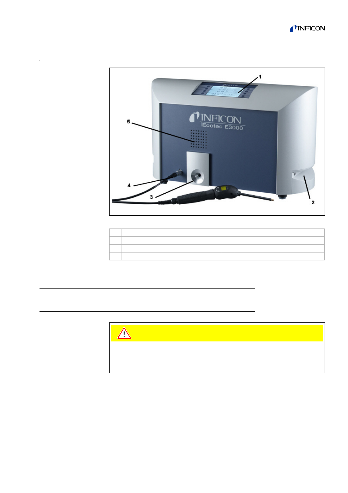
1.5 Instrument Views of the Ecotec E3000
Caution
Fig. 1-2 Instrument views of Ecotec E3000
Pos. Description Pos. Description
1 Main display 4 Lemo Connector for sniffer line
2 Handle for carrying the Ecotec E3000 5 Speaker
3 ECO-Check reference leak
1.6 Installation
1.6.1 Set up
The weight of the Ecotec E3000 exceeds 25 kg.
It therefore should not be carried by one single person.
The Ecotec E3000 may tip off its base and injure people.
Place the Ecotec E3000 on a stable base.
How to remove the transportation lock:
The transportation lock is located on the bottom side of the Ecotec E3000 main unit
and consists of a yellow knurled screws. Please remove this screw before startingup the Ecotec E3000. The Ecotec E3000 is supplied ready for operation. Initial startup is described in Section 3.1.
kina22e chapter 1.fm technical handbook(1206)
General Information 1-13
Page 24
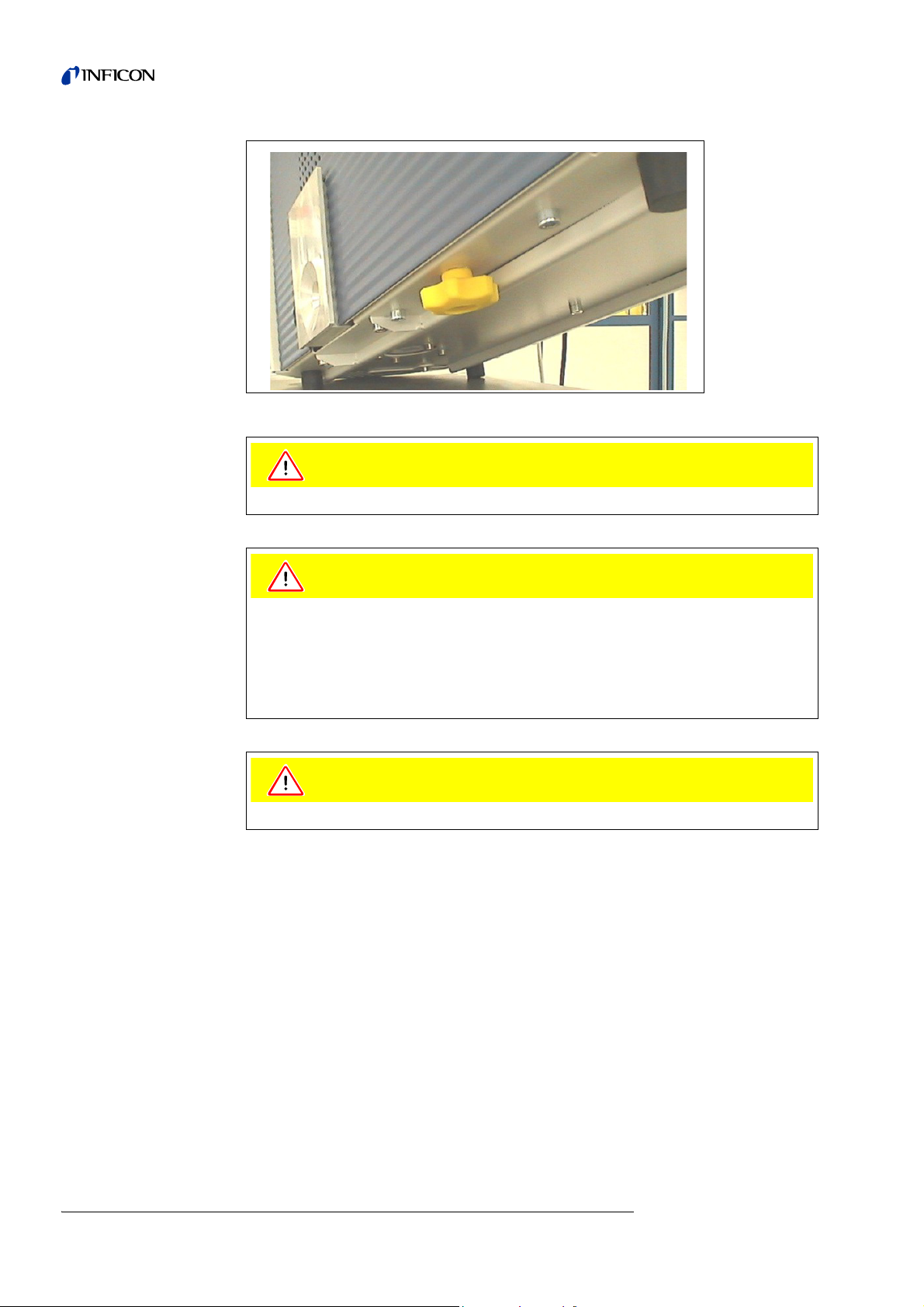
Fig. 1-3 Removing the transportation lock before starting
Caution
Caution
Caution
Before installation remove the transportation lock.
In order to ensure adequate ventilation of the Ecotec E3000, a space of at least
20 cm (8 in.) must be kept unobstructed to the sides. The clearance at the rear must
be no less than 10 cm (4 in.). Moreover, the Ecotec E3000 handles for carrying the
leak detector at the sides of the main unit must not be covered at any time as these
acts as air inlet and outlet. Avoid the presence of heat sources in the vicinity of the
Ecotec E3000.
Make sure that you can always reach the mains plug.
1-14 General Information
kina22e chapter 1.fm technical handbook(1206)
Page 25

1.6.2 Mechanical Connections
ECO-Check Reference leak (optional)
Please insert the ECO-Check reference leak into the opening in the housing of the
main unit. Make sure that the Sub-D plug is properly connected with the ECO-Check
leak.
Notice: When properly inserted, the ECO-Check reference leak will still protrude by
approx. 10 mm.
On first usage of your ECO-Check you need to initialize the use of this reference leak
in the Ecotec E3000 software menu.
Please perform the following steps:
1 Insert the ECO-Check into the appropriate opening of the Ecotec E3000
2 In the software menu go to HISTORY & MAINTENANCE / REPLACE ECO-CHECK.
Notice: The Ecotec E3000 must be set to
submenu (See section 4.5.3). Go to
ADVANCED MODE for access to this
SETTINGS / DISPLAY / USER MODE)
3 On the certificate, which is delivered with the ECO-Check, you will find a serial
number and a 12-digit-code. Enter the serial number in the first line of the open
submenu and the 12-digit-code in the second line and press OK.
Notice: The ECO-Check reference leak must be installed in the Ecotec E3000
when pressing
Fig. 1-4 Initializing the ECO-Check reference leak
OK.
SL3000 Sniffer line
In order to operate the Ecotec E3000 it is essential for the sniffer line to be
connected. The connection for the sniffer line is located at the front of the Ecotec
E3000 left of the ECO-Check reference leak.
Insert the plug into the opening with the red dot on the plug and the slot in the front
cover aligned until the connector engages. To disconnect the plug, retract the
coupling and remove the probe’s line.
kina22e chapter 1.fm technical handbook(1206)
General Information 1-15
Page 26
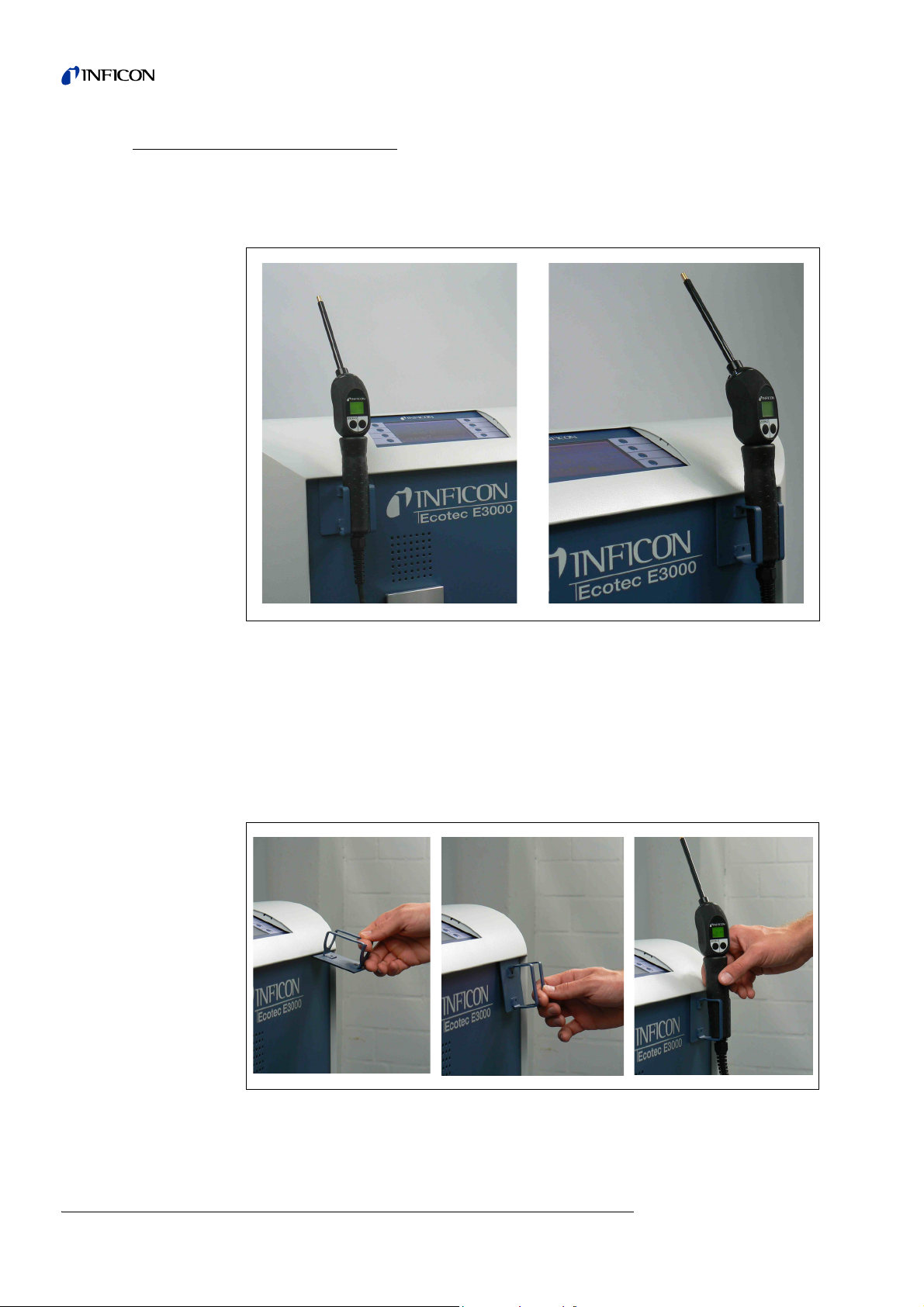
Holder for SL3000 sniffer line (optional)
An optional holder for the SL3000 sniffer line is available as cat.-no. 525-006. The
holder may be installed on the right or left side of the main unit (for right- or left
handed operators) as shown in Fig. 1-6.
Fig. 1-5 Usage of sniffer line holder
The installation is described in Fig. 1-6. There are two little slots on the front side at
the very top area of the blue square front of the main unit.
Hold the holder horizontally and then insert the two little hooks of the holder into the
two slots (either on the right or the left side).
With the hooks still inserted, let the holder flap down. It will automatically attach to
the metal front by the magnet on the backside of the holder.
Now insert the sniffer probe grip into the opening of the holder and let it sink down
until it rests in the holder.
Fig. 1-6 Installation of sniffer line holder
1-16 General Information
kina22e chapter 1.fm technical handbook(1206)
Page 27

Water protection tip (optional)
If you intend to perform leak testing on parts that are not completely dry (e.g. due to
condensation after performance testing), we strongly recommend to use a water
protection tip.
To install the water protection tip,
1 screw off the metallic capillary filter at the very end of the sniffer tip and
2 install the water protection tip instead.
Notice: Please do not forget to re-install the little rubber seal when switching to the
water protection tip.
Fig. 1-7 Installing water protection tip
ECO-Check Reference leak (optional), for helium and hydrogen only
If detecting helium or hydrogen, a ECO-Check reference leak may be used for
internal calibration. The ECO-Check reference leak has to be inserted to the Ecotec
E3000 (see section 2.3.3).
On first usage of your ECO-Check you need to initialize the use of this reference leak
in the Ecotec E3000 menu.
Please perform the following steps:
1 Insert the ECO-Check into the appropriate opening of the Ecotec E3000
2 In the software menu go to HISTORY & MAINTENANCE /REPLACE ECO-CHECK.
Notice: The Ecotec E3000 must be set to
submenu (See section 4.5.3). Go to
3 On the certificate, which is delivered with the ECO-Check, you will find a serial
number and a 12-digit-code. Enter the serial number in the first line of the open
submenu and the 12-digit-code in the second line and press OK.
USER MODE „ADVANCED“ for access to this
SETTINGS / DISPLAY / USER MODE.
kina22e chapter 1.fm technical handbook(1206)
General Information 1-17
Page 28

For Ecotec E3000RC only
Warning
1
23 456
The Ecotec E3000RC has no built-in display unit but a connectors plate is mounted
instead. Please connect the external display unit with the 5 m connecting table (Cat.no. 551-102).
Fig. 1-8 Ecotec E3000RC with external display unit for: (a) bench top use (left side),
(b) rack mounting (right side)
1.6.3 Electrical Connections
Fig. 1-9 Electrical connections
Pos. Description Pos. Description
1 Headphone port 4 Name plate
2 I/O Port 5 Power switch
3 RS232 interface 6 Power connector
Notice: The local regulations for electrical connections must always be observed
(in Germany VDE 0100). The mains voltage rating for the Ecotec E3000
can be read off from the name plate left of the power switch. The mains
voltage setting of the Ecotec E3000 is fixed and can not be changed. A
separate fuse for each of the mains conductors has been integrated into
the mains socket (Fig. 2-1/6).
Only 3-core mains cables having a protective ground conductor must be used.
Operation of the Ecotec E3000 with the ground conductor unconnected is not
permissible.
kina22e chapter 1.fm technical handbook(1206)
1-18 General Information
Page 29

The mains voltage is applied to the Ecotec E3000 via the detachable mains cable
Caution
which is supplied with the Ecotec E3000. A main power socket is available for this
purpose at the rear of the Ecotec E3000.
Before connecting the Ecotec E3000 to the mains you must make sure that the
mains voltage rating of the Ecotec E3000 coincides with the locally available mains
voltage.
1.6.4 RS232 Interface
The Ecotec E3000 is equipped with a RS232 interface which is located on the rear
right side of the main unit. This interface is of the DCE type (Data Communications
Equipment) and allows the connection of a PC for monitoring and data logging. The
connection is provided through a commercially available Sub-D plug. For further
information see “Interface Description Ecotec E3000” (kins22e1).
1.6.5 I/O Port
The I/O part allows communication with external equipment via analog data. For
details see Section 7.2.
Through this connection some functions of the Ecotec E3000 can be controlled
externally or measurement data or the Ecotec E3000 status may be communicated
to external equipment.
Through relay changeover contacts the trigger levels as well as the operating mode
(Ready) of the Ecotec E3000 may be monitored.
kina22e chapter 1.fm technical handbook(1206)
General Information 1-19
Page 30

1-20 General Information
kina22e chapter 1.fm technical handbook(1206)
Page 31

2 How the Instrument Works
ECOTEC E3000
MVP 015
Transpector
TPD 021
Sniffer probe
external
particle
filter
internal
particle
filter
flow divider 1
flow divider 2
flow meter
flow
limiter 1
flow
limiter 2
pv
1
2
2.1 Description of the Functions
The Ecotec E3000 is capable of detecting and quantifying the refrigerant sucked in
through the sniffer line by means of a selective mass spectrometer.
The Ecotec E3000 is composed of the following principal subassemblies:
• a quadrupole mass spectrometer as the detection system
• a high vacuum pump system
• an inlet system for the gas flow
• the corresponding electrical and electronic subassemblies for supplying power
and for signal conditioning.
kina22e chapter 2.fm technical handbook(1206)
Fig. 2-1 Vacuum Diagram of the Ecotec E3000
The mass spectrometer only operates under high vacuum conditions, i.e. the
pressure in the mass spectrometer must always stay below 10
-4
mbar. This vacuum
is generated by the turbo molecular pump with the support of the diaphragm pump.
The pressure pV between the two pumps is measured with a piezo resistive
measuring system and this pressure lies in the range between 4 to 10 mbar while in
the measurement mode. This pressure must not exceed a value of 10 mbar as
otherwise the turbo molecular pump will not be capable of maintaining the vacuum
in the mass spectrometer.
How the Instrument Works 2-1
Page 32

2.2 Description of the Subassemblies
2.2.1 Backing Pump
A diaphragm pump in the Ecotec E3000 serves as the backing pump. All data and
further information on this pump are given in the Operating Instructions of the pump.
The backing pump generates the fore pressure required for operation of the turbo
molecular pump and sucking in of the gas through the sniffer line.
2.2.2 Turbo Molecular Pump (TMP)
Built into the Ecotec E3000 is a turbo molecular pump with upstream compression
stage. The turbo molecular pump generates the high vacuum necessary for
operation of the mass spectrometer, whereas the compression stages permits
relatively high backing pressures without impairing the ultimate pressure in the mass
spectrometer. The TMP has a side connection. Thus a part of the taken in gas is
pumped through the TMP into the first stage of the diaphragm pump. This gas load
prevents the accumulation of water vapour in the diaphragm pump.
2.2.3 Mass Spectrometer
The TranspectorTM mass spectrometer is composed of the ion source, the separator
and the ion collector. The ion source ionizes neutral gas particles and generates an
ion beam. The positively charged ions are accelerated out of the ion source and then
enter the Quadrupole field. This field acts like a filter. Only the ions to which the
system has been adjusted are able to meet the separating conditions and arrive at
the ion collector, where their presence can be measured as a current by an
electrometer amplifier. This current is the output signal which is then used to
calculate the leak rates. Two cathodes have been integrated within the ion source. If
one cathode fails the other is selected automatically.
2.2.4 Quadrupole Supply
This subassembly generates all the voltages and currents required for operation of
the mass spectrometer. Faults in the mass spectrometer are detected and signalled
to the control assembly. The control assembly monitors the mass spectrometer
supply.
2.2.5 Control
The control assembly (microprocessor) is the central assembly of the Ecotec
E3000’s electronics. All other subassemblies are controlled and monitored by this
assembly. The microprocessor which is located here is thus continuously informed
about the status of the entire Ecotec E3000 and can respond accordingly. In order to
accept commands from the operator and to output measured values and messages,
the control subassembly is linked to the display unit.
kina22e chapter 2.fm technical handbook(1206)
2-2 How the Instrument Works
Page 33

2.3 Displays and User Interfaces
1
2
2.3.1 Main unit display
This subassembly is used to communicate with the operator. It accepts commands
from the 8 keys on both sides of the display and outputs measurement results and
messages via the display.
Fig. 2-2 Main unit display
Pos. Description Pos. Description
1 Menu buttons 1 to 4 2 Menu buttons 5 to 8
for Ecotec E3000RC only
The Ecotec E3000RC has a connectors plate for the external display unit instead of
the built-in main unit display. Two LED's left of the plug provide information about the
status of the Ecotec E3000RC, even when the external display unit is disconnected:
• The green LED will indicate that the Ecotec E3000RC is in operation (switched
on). The green LED will show continuous green light if an external display unit is
connected and will blink if no external display unit is detected.
• The red LED will be blinking in case of an error message, continuous red light
indicates a warning.
kina22e chapter 2.fm technical handbook(1206)
How the Instrument Works 2-3
Page 34

Fig. 2-3 Connector plate with LEDs
1
3
2
If no display unit is connected, error messages or warnings may be acknowledged
by pressing both buttons of the sniffer line simultaneously.
The external display unit also offers four buttons:
• The START / STOP buttons have no function (the external display unit may also
be used with other INFICON leak detectors which need these buttons)
• The MENU button will open the software menu.
• The ZERO button will set the current background reading to zero. (For details on
the ZERO function see Section 4.4.1)
2.3.2 Sniffer line with probe display
The probe handle also offers a small display for operating the Ecotec E3000 remotely
without access to the main unit during normal leak detection operation.
2-4 How the Instrument Works
Pos.
Fig. 2-4 Sniffer line with probe display
In addition to the display, the sniffer probe offers two press buttons. The left button
will function as the ZERO button in any operating mode. By pressing the left button
the current background reading is set to ZERO. The ZERO function can be disabled
by holding the ZERO button for 2 seconds. A beep will indicate that the ZERO
function has been successfully switched off. The ZERO function can be re-activated
by pressing the ZERO button once again. For details on the ZERO function see
section 4.5.1)
Description
Probe display
1
Button
2
ZERO button
3
kina22e chapter 2.fm technical handbook(1206)
Page 35

The right probe button is used for different functions depending on the current
Warning
operating mode the Ecotec E3000 is set to.
Fig. 2-5 Probe handle
The probe handle also offers some LEDs in the flange of the sniffer tip in order to
illuminate the location currently being leak tested.
Do not stare into the LEDs intentionally for extended times or at a close distance as
this may cause permanent damage to the eye.
The LEDs offer some bundled light. The intentional starring suspends the lid closing
reflex and also the eyes do not move anymore which may lead to overheating of the
retina.
When looking into the LEDs „incidentally“ the eye is protected by the lid closing
reflex. Also the permanent movement of the eyes prevents overheating and
consequent damage of the retina.
kina22e chapter 2.fm technical handbook(1206)
How the Instrument Works 2-5
Page 36

2.3.3 Built-in ECO-Check reference leak
A built-in ECO-Check reference leak is available for the Ecotec E3000. The ECOCheck reference leak can be used for verifying the correct functioning of the Ecotec
E3000 including the correct calibration and can also be used for re-calibrating the
Ecotec E3000 if necessary.
The ECO-Check reference leak is inserted in the front of the housing. Insertion of the
sniffer tip into the cone-shaped test leak opening is automatically detected via a light
barrier.
Fig. 2-6 Built-in ECO-Check reference leak
Fig. 2-7 ECO-Check reference leak detached from the main unit for remote use
2-6 How the Instrument Works
kina22e chapter 2.fm technical handbook(1206)
Page 37

In cases where the main unit is placed in a difficult or inconvenient to access area
the built-in ECO-Check reference leak can be removed from the main unit for easier
access and connected to the main unit via the Sub-D connector with a commonly
available extension cord. The ECO-Check reference leak can then be placed in an
area where it is convenient for the operator to be reached.
Fig. 2-8 Connections for remote use
Pos. Description Pos. Description
1 Connector at built-in test leak 2 Connector at
Ecotec E3000 housing
Notice: The ECO-Check reference leak is not part of the Ecotec E3000 shipment
and needs to be ordered as a separate part no. (see section 1.3.3).
Notice: If you have not purchased the ECO-Check reference leak, warning 71 (“No
communication with test leak”) will be issued on first start-up. Please go to
SETTINGS / INTERFACES /ECO-CHECK and set the ECO-Check to “DISABLED”
to prevent future warnings (see section 4.6.7)
The Ecotec E3000 must be set to
submenu (See section 4.5.3). Go to
USER MODE „ADVANCED“ for access to this
SETTINGS / DISPLAY / USER MODE.
kina22e chapter 2.fm technical handbook(1206)
How the Instrument Works 2-7
Page 38

2-8 How the Instrument Works
kina22e chapter 2.fm technical handbook(1206)
Page 39

3 Operation of the Ecotec E3000
3.1 Start-Up
Assemble the Ecotec E3000 (see Section 1.5). Connect the mains cord and the
sniffer line, and then switch on the Ecotec E3000. The mains switch is located on the
rear.
Fig. 3-1 Connection of the mains cord
Pos. Description Pos. Description
1 Power Switch 2 Power cord connection
The Ecotec E3000 will automatically start a self test and run-up procedure. This
takes about 2 minutes max. During the start-up the fore line pressure, the flow, the
rotation speed of the turbo molecular pump will be displayed.
Fig. 3-2 Start-up menu
The individual steps are indicated on the display. In the case of unfavorable
conditions, switching on of the emission may take several minutes.
kina22e chapter 3.fm technical handbook(1206)
Operation of the Ecotec E3000 3-1
Page 40

After switching on and completion of the run-up phase the Ecotec E3000 will be
ready to make measurements. There is no separate start function. The sniffer lines
are designed to maintain an inlet pressure low enough to make measurements.
Notice: The Ecotec E3000 will only operate after having connected the sniffer line.
Upon delivery, the data of the following gases are programmed in the factory for the
measurements, and these gases are indicated on the display:
R134a, R600a, R22, He
This selection of gases may be changed at any time.
A calibration in accordance with Section 3.5 is recommended 20 minutes after having
switched on the Ecotec E3000 on at the earliest (warm-up phase).
Notice: If you have not purchased the ECO-Check reference leak, warning 71 (“No
communication with test leak”) will be issued on first start-up. Please go to
Settings / Interfaces / ECO-Check and set the ECO-Check to “disabled” to
prevent future warnings (see section 4.6.7)
3.2 Controls on the main display unit
All set-up and control functions are integrated into the main display unit via the menu
structure. The functions of the 8 control keys are displayed on the LC display. During
measurements the main interface is the probe handle display giving all necessary
information for proper leak testing.
After start-up the Ecotec E3000 will automatically go into measurement mode.
Fig. 3-3 Measurement screen in standard operation mode
Pos. Description Pos. Description
1 Audio volume buttons 3 Calibration button
2 Menu button 4 Info button
3-2 Operation of the Ecotec E3000
kina22e chapter 3.fm technical handbook(1206)
Page 41

Bar graph display
Warning
The currently detected leak rates for all selected gases will be display in a bar graph
for each gas independently in logarithmic scale. On the upper left side of each bar
graph the selected gas type is indicated. The currently selected trigger level is
indicated by a black line, the currently selected search level is indicated by a dotted
line. If the search level is exceeded the shape of a bell is displayed right of the gas
name, if the trigger is exceeded the bell starts to blink (to “ring”). The pointer on the
right side of the bar graphs indicates the currently detected gas which gas is also
currently being displayed on the probe display.
Fig. 3-4 Measurement screen with leak
Pos. Description
1 Gas type
2 Indication of currently highest leak rate signal
3 Only when in
present
4 Indication that
5 ZERO enabled
6 Indication of trigger level being exceeded
7 Bar graph
8 Indication of active warning
9 Audio volume level
ADVANCED mode and operating in IGS mode: indication of interfering gas being
Ecotec E3000 has switched to filament B already
Audio Volume Buttons
The hearing can be harmed by the audio alarm.
The acoustic output can exceed a level of 85dB(A).
Do only expose to the audio alarm for a short time or use ear protection.
The two center keys on the left side of the display allow to adjust the volume of the
alarm sound at any time. When pressing any of the two buttons the currently selected
volume will be demonstrated by the loudspeaker as well as by a bar graph in the
status line. The selected value is also displayed as the first entry of the status line at
the bottom of the display and only applies to the loud speaker in the main unit. For
kina22e chapter 3.fm technical handbook(1206)
selecting different types of alarms see section 4.5.2.
Operation of the Ecotec E3000 3-3
Page 42

Menu Button
Cal Button
ZERO Button
The button on the bottom left side of the display will open the main menu at any
time. The menu mode offers the user many possibilities of entering Ecotec E3000
settings and special functions.
With the button on the upper right side of the display an external calibration of the
Ecotec E3000 can be started at any time. For details on how to perform an external
calibration see Section 3.5.3.
Info Button
Status line
When shortly pressing the
be updated. Holding the
ZERO button, the ZERO level for all selected refrigerants will
ZERO button for more than 2 seconds will disable the ZERO
function. In this case the ZERO indicator will be removed from the status line. For
details on the
When pressing the
ZERO function see Section 4.5.1.
i info button (bottom right side of the display) information on the
status of the Ecotec E3000 will be displayed. For details see section 3.4.3.
In the bottom line of the main display status information is indicated. First the
currently selected volume for the audio alarm is stated. Next, a small black triangle
with an exclamation mark may indicate an active warning. If the
ZERO function is
enabled the word “ZERO” is listed in the status line next.
If the first filament (filament A) is burned and the Ecotec E3000 automatically
switched to the second filament (filament B), an indication “Fil. B” is displayed in the
status line.
Only when operating in
ADVANCED mode and with IGS activated, the indication “IGS”
is displayed in the status line as long as interfering gas is detected.
3-4 Operation of the Ecotec E3000
kina22e chapter 3.fm technical handbook(1206)
Page 43

3.3 Controls on the probe display unit
1
3
2
On the display of the probe handle similar information as on the main display is
shown.
Pos. Description
1 Bar graph indicating the leak rate
2 Absolute leak rate
3 Gas currently detected
Fig. 3-5 Sniffer display in standard operation mode
The currently detected leak rate is indicated as a bar graph. In a second line the
numerical leak rate (in the same unit of measurement as on the main display) is
shown. In the third line the type of gas detected is stated (e.g. R134a).
The sniffer probe offers two press buttons. By pressing the left button the current
background reading is set to
ZERO button until a beep will indicate that the ZERO function has been successfully
switched off. The
again. For details on the
The right probe button allows to switch the bar graph display to the next of the up to
four chosen gases to be detected. This button is inactive if only one gas has been
selected. For details on this setting please refer to Section 4.5.3.
ZERO function can be re-activated by pressing the ZERO button once
ZERO. The ZERO function can be disabled by holding the
ZERO function please refer to 4.5.1. ZERO.
kina22e chapter 3.fm technical handbook(1206)
Operation of the Ecotec E3000 3-5
Page 44

3.4 Performing measurements
Warning
Caution
The Ecotec E3000 offers two modes of operation:
• The Standard Operation Mode (compatible to the EcotecII mode)
• The I•Guide Operating Mode
Danger of electric shock.
Do not touch voltaged parts with the sniffer tip. Test samples need to be
disconnected from electricity before leak testing.
Do not suck in any liquids.
A water-protection tip is available (Cat.-No. 12246) which will protect the Ecotec
E3000 against intake of liquids if necessary. For details on how to install the water
protection tip see 1.6.2)
3.4.1 Standard Operation Mode
Provided the Ecotec E3000 has been set-up to meet the requirements of the
particular application and it has been calibrated (see Section 3.5), a measurement is
run as follows:
First briefly operate the
Ecotec E3000 eliminates all interfering influences which may affect the
(i.e. the detection limit of 0.05 g/a).
Next hold the tip of the sniffer as close as possible to the suspected leak, if required
the tip may even touch the test object.
If a welded seam or alike needs to be tested, the tip should be moved at a velocity of
no more than 10 cm/s (4 inch per second) along the welded seam. The distance
between tip and test sample should be as small as possible.
If a leak is detected the bar will grow. The Ecotec E3000 continuously compares the
measured leak rates with the programmed trigger levels.
If the trigger is exceeded the background color of the probe display will change from
green to red. At the same time an alarm sound will be released by the speaker in the
probe handle and the probe handle will start to slightly vibrate.
As an additional indication of exceeding the trigger value the three white LEDs in the
flange of the sniffer tip will start flashing.
ZERO button on the sniffer probe. This will ensure that the
ZERO level
3-6 Operation of the Ecotec E3000
kina22e chapter 3.fm technical handbook(1206)
Page 45

Fig. 3-6 Sniffer display when detecting a leak
The display limits for the different units of measurement are summarized in the table
below.
Unit Lower display limit Upper display limit
g/a 0.05 1,000
oz/yr 0.002 1,000
ppm 0.5 100,000
mbar l/s 1x10
Pa m³/s 1x10
atm cc/s 1x10
Torr l/s 1x10
-7
-8
-7
-7
9.9x10
9.9x10
9.9x10
9.9x10
-2
-3
-2
-2
The lower display limit may be increased by the user. Please refer to Section 4.5.3
for how to edit the lower display limit.
As soon as an acoustic alarm sounds, the tip should be removed from the spot being
tested. After displaying a constant leak rate the ZERO button should be pressed
again to repeat the test. Thus, a measurement error can be prevented and the leak
can be located.
kina22e chapter 3.fm technical handbook(1206)
Operation of the Ecotec E3000 3-7
Page 46

3.4.2 I•Guide Operating Mode
The I•Guide operating mode has been introduced to support the operator in applying
proper sniffer leak detection technique.
The I•Guide operator guiding mode allows to store pre-programmed parameters for
different units under test. The number of locations that need to be tested per
specimen, the time each location needs to be tested for as well as the time required
to move to the next location may be programmed. In addition, a maximum allowable
global leak rate for the total unit under test is stored. In the I•Guide mode up to 10
pre-programmed testing procedures can be stored.
Notice: If the number of locations to be tested is set to 0, the Ecotec E3000 will
operate in a continuous mode without checking for a global leak rate but
still issue the timer signal for proper testing.
3.4.2.1 Starting the I•Guide Mode
To start the I•Guide Mode go to the main menu and choose SETUP I•GUIDE. In the
opening menu go to the top line item and change the setting to
side push button and press
enabled I•Guide program in the list. A message screen will pop-up notifying the
operator that I•Guide has been activated and therefore only one or two gases will be
measured from now on (the gas selected in the I•Guide program you choose).
For how to set-up and I•Guide program please refer to Section 4.5.4.
ON with the left hand
OK. The Ecotec E3000 will automatically choose the first
To switch back to the Standard Operation Mode select “I•G
Fig. 3-7 Switching to I•Guide Mode
UIDE OFF” and press “OK”.
3-8 Operation of the Ecotec E3000
kina22e chapter 3.fm technical handbook(1206)
Page 47

3.4.2.2 Selecting an I•Guide Program
To open the “SELECT I•GUIDE” menu press the ”PROGRAM LIST” button on the right side
of the display.
Fig. 3-8 Measuring Screen in I•Guide Mode
Pos. Description
1 program list
In the opening “
an arrow in front of the program name. Highlight the program number you intend to
use and press
Fig. 3-9 Selecting an I•Guide program
3.4.2.3 Using an I•Guide Program
In the measuring screen of the I•Guide operating mode the selected program, the
gas type stored in the program as well as the summarized global leak rate will be
displayed.
In the I•Guide message line the Ecotec E3000 will prompt the user for action. First it
will ask to move to the first testing position.
Also on the probe display the message “okay pos. 1?” will be shown. Please confirm
with the right probe button that the sniffer tip has reached the right location.
SELECT I•GUIDE” menu the currently selected program is indicated by
OK. The new program is now loaded.
kina22e chapter 3.fm technical handbook(1206)
Operation of the Ecotec E3000 3-9
Page 48

Fig. 3-10 I•Guide screens during measurement (one gas selected)
6
7
3
Pos. Description Pos. Description Pos. Description
1 Selected program 4 Elapsing measuring 6 ZERO button
2 Gas type stored in the time 7 I•Guide button
selected program 5 Summarized global
3 I•Guide message leak rate per unit
under test
Fig. 3-11 I•Guide screen during measurement (two gases selected)
Pos. Description Pos. Description
1 Selected program 4 Elapsing measuring time
2 Gas type stored in the selected program 5 Summarized global leak rate per
3 I•Guide message unit under test
After the first location has been confirmed the message “leak check point1” will be
indicated on the main unit display and the elapsing measurement time (stored in the
testing program) will be shown in the lower part of the menu page.
Please make sure to hold the sniffer tip in the right testing location during the total
measuring time. During this time a ticking sound will be issued by the main unit and
a beep will indicate that the measuring time has elapsed and the sniffer tip can be
moved again.
After the measurement time has elapsed the message “Move to point 2” will be
displayed on the main unit. The probe display will read “tip to pos. 2”.
Please move the sniffer tip to the next testing location and if the wait time indicated
in the display has elapsed, you may start the next measurement.
If the operator tries to start the next measurement before the wait time has elapsed,
3-10 Operation of the Ecotec E3000
kina22e chapter 3.fm technical handbook(1206)
Page 49

the message “please wait” will be displayed in the message line until a next
measurement is allowed.
Please confirm that the sniffer tip has been positioned properly by pressing the right
probe button so that the next measurement can be started.
Fig. 3-12 I•Guide screens requesting the next location
After checking the pre-programmed number of locations, the result of the testing for
the total unit under test will be displayed as shown in the following screen shots:
Fig. 3-13 Result of I•Guide program: unit under test passed
Pos. Description Pos. Description
1 Program name 3 Cycle counter
2 Gas type 4 Results of each location tested
The selected testing program as well as the gas type stored in the program will be
stated followed by the actual program cycle number.
The program cycle counter is increased by 1 after each completed cycle. The cycle
counter may be reset manually (in the Setup I•Guide menu, see section 4.5.4).
The cycle counter is also automatically reset on power off.
Next the summarized global leak rate is started. If the global leak rate is lower than
the global leak rate trigger the message "Global leak check okay!" will be displayed
followed by the testing results for each tested location.
If the summarized global leak rate exceeds the global trigger the message "Global
trigger exceeded!" will be displayed.
kina22e chapter 3.fm technical handbook(1206)
Operation of the Ecotec E3000 3-11
Page 50

Fig. 3-14 Result of I•Guide program: unit under test failed
The sniffer line display will switch to red background color if the global trigger is
exceeded (or at least one if two gases are selected for the program used).
The gas exceeding the global trigger is displayed in the results list. However, you can
switch between the results of the two different gases with the "A" and "B" buttons on
the right side of the display.
The display of the sniffer line will show the results for the two different gases
alternating automatically.
By pressing the right probe button the next testing cycle may be started.
3.4.3 The Info Page
By pressing the INFO button on the main display a general info page will open.
Information on the software version used, the number of operating hours, the serial
number, time & date and the currently selected alarm type will be stated. Also, the
selected gases with their mass position will be listed. Gases that are disabled will be
marked as such. For gases that are enabled also the currently selected trigger level
will be started.
Fig. 3-15 Info page without errors or warnings
If an active warning exists this will be displayed in the info page instead of the gas
info lines as shown below.
3-12 Operation of the Ecotec E3000
kina22e chapter 3.fm technical handbook(1206)
Page 51

Fig. 3-16 Info page with active warning
When operating in I•Guide Mode, the info page will state information about the
currently selected program: the selected program name, the gas used for this
program, the number of points to be checked for this program, the selected
measuring and wait time as well as the global trigger.
If two gases are selected for the I•Guide program, the gas type A/B and the global
trigger A/B will be displayed alternatively.
Fig. 3-17 Info page in I•Guide mode
kina22e chapter 3.fm technical handbook(1206)
Operation of the Ecotec E3000 3-13
Page 52

3.5 Calibration and Self-Test
The Ecotec E3000 can be calibrated internally with the built-in ECO-Check reference
leak or externally with an external calibrated leak (Cat. No. 122 20 - 122 35).
The built-in ECO-Check reference leak can be used for a self-test of the Ecotec
E3000 as well as for calibration of gases that are measured at mass positions
between 40 and 105 amu. If a gas is measured on a mass position below 40 amu or
above 105 amu it will be permitted for internal calibration in the “
A ECO-Check reference leak (cat. no. 521-001) maybe connected to the Ecotec
E3000 remotely and be used for internal calibration and verification of the calibration
(proof function) for helium and hydrogen. Internal calibration and verification may be
performed accordingly.
Notice Do not calibrate the Ecotec E3000 during the first 20 minutes after start-up.
Also a verification of the calibration may lead to wrong results in the first 20
minutes after start-up.
Only confirm and continue with the calibration or proof, if the real warm-up
time has been longer than 20 minutes (e.g. after a quick restart of the
Ecotec E3000)
Notice: When detecting hydrogen a longer warm-up time is required. For hydrogen
please calibrate the Ecotec E3000 not before 1 h after start-up.
EDIT GAS” menu.
Notice: The accuracy of an internal calibration is less than the accuracy of a
calibration with an external calibrated leak.
Notice: The ECO-Check reference leak is a temperature compensated leak. It
must only be used when electrically connected to the main unit, either
when inserted into its port or when connected to the main unit via a Sub-C
extension cord. The leak rate printed onto the body of the ECO-Check is
only valid at 20°C (68F) and will vary greatly with temperature.
To compensate for this the ECO-Check reference leak is equipped with a
temperature sensor and a compensation curve is stored in the software
which automatically compensates the test leak rate for changes in
temperature when connected to the main unit.
A calibration or verification with the ECO-Check reference leak not being
connected to the main unit will cause a wrong calibration of the Ecotec
E3000 and / or will lead to wrong testing results.
3-14 Operation of the Ecotec E3000
kina22e chapter 3.fm technical handbook(1206)
Page 53

3.5.1 Verifying a calibration (proof function)
Notice: The description of how to perform a verification applies to the use of the
ECO-Check reference leak for detecting helium or hydrogen (forming gas)
accordingly.
Notice: A verification can only be performed while the Ecotec E3000 is in
measurement mode (not when the main menu is opened or during startup).
If the sniffer tip is inserted into the opening of the ECO-Check reference leak a
verification of the calibration (proof function) will be started automatically.
While holding the sniffer tip in the test leak opening, the Ecotec E3000 will check the
reading from the ECO-Check. Afterwards the operator will be requested to remove
the sniffer tip from the leak opening.
Notice: Any time during the verification procedure an internal calibration may be
started by pressing either the right sniffer probe button or the CAL button
on the main display.
The results of the verification will be displayed in a summarizing screen.
Fig. 3-18 Results of proof function
For gases that are enabled for internal calibration either “Check ok” or “Recalibration
required” will be stated.
For gases that are disabled for internal calibration “Gas disabled” will be stated.
For gases that cannot be calibrated with the ECO-Check because of very high or
very low mass positions, “gas specific check impossible” will be listed.
For returning to the measuring mode, please press the right probe button or press
“
OK” on the main display.
kina22e chapter 3.fm technical handbook(1206)
Operation of the Ecotec E3000 3-15
Page 54

3.5.2 Internal calibration
Notice: The description of how to perform an internal calibration applies to the use
Notice: An internal calibration can only be performed while the Ecotec E3000 is in
If the sniffer tip is inserted into the opening of the ECO-Check reference leak with the
right probe button pressed while in measurement mode, a calibration will be started
automatically.
While holding the sniffer tip in the test leak opening, the Ecotec E3000 will first look
for a baseline, find the Argon peak of the air and then measure the test leak.
Afterwards the operator will be requested to remove the sniffer tip from the leak
opening.
After completion of the calibration a screen summarizing the results of the calibration
will be displayed.
For gases that are allowed for internal calibration the old and new calibration factor
and the old and new relative peak position will be stated.
of the ECO-Check reference leak for detecting helium or hydrogen (forming
gas) accordingly.
measurement mode (not when the main menu is opened or during startup).
Fig. 3-19 Results of internal calibration
If a gas cannot be calibrated internally, in the listing the message “int. calibration
impossible” will be displayed for these gases.
If a gas has been disabled for internal calibration in the “
message “Gas disabled” will be displayed.
To avoid unintended overwriting of a previous external (more accurate) calibration,
the operator needs to “confirm to save the new values”.
The saving of the new values may be password protected.
3-16 Operation of the Ecotec E3000
EDIT GAS” menu, the
kina22e chapter 3.fm technical handbook(1206)
Page 55

3.5.3 External calibration
For external calibration it is recommended to use leak rates > 2 g/a (0.07 oz/yr) when
calibrating the Ecotec E3000.
Notice: If significantly increased backgrounds are prevalent in your production
Notice: If a calibration is started during the first 20 minutes after power on, a
The external calibration is a semi-automatic process during which the user will have
to follow some instructions. The calibration process may be started via the “
button from the measuring mode at any time (except when the menu is open or the
function has been locked). A running calibration process may be cancelled by
operating the “
After pressing the CAL button the currently selected gases with their selected mass
positions will be listed. By pressing one of the four buttons on the right side of the
display, the gas to be calibrated externally will be selected. Only gases that are
currently enabled will be available for calibration.
environment, larger leak rates for the calibration leak may be required.
warning will be issued. Only confirm and continue with the calibration if the
real warm-up has been longer (e.g. after a quick restart of the Ecotec
E3000)
CAL” -
ESC” button.
Notice: If more than one gas is currently selected for measurement, a calibration
will be required for each gas separately.
Fig. 3-20 Gas selection for external calibration
Please check whether the leak rate and the gas type displayed equals the leak rate
and the gas type of the external leak you plan to use. If the leak rate is different press
“
EDIT LEAK RATE” and enter the correct leak rate value. Press “START” afterwards to
begin with the calibration process.
kina22e chapter 3.fm technical handbook(1206)
Operation of the Ecotec E3000 3-17
Page 56

Fig. 3-21 Setting-up the leak rate of the external leak
Please hold the sniffer tip to the outlet of the external calibrated leak. Hold the sniffer
tip steady and very close to the opening, however, do not clog the opening with the
sniffer tip.
Some air also needs to enter the sniffer tip in addition to the refrigerant from the
external calibrated leak. If the leak rate signal indicated by the bar graph is stable
press “
OK”.
Keep holding the sniffer tip steady in front of the opening while the Ecotec E3000
reads the leak rate of the calibrated leak. During this time the text “Please wait…” will
be displayed.
When the analysis of the calibrated leak signal is completed a message “sniff air!”
will be displayed.
Remove the sniffer tip from the opening of the calibrated leak and hold the sniffer tip
into the air, as far as possible from any sources of refrigerant. Wait until the bar graph
shows a stable signal again and press “
OK” once more.
Notice: When calibrating for helium or Hydrogen, the air signal will decrease only
slowly and the time for the air signal to stabilize may be as long as 30 sec.
Please do not confirm the air signal too early, as this will lead to a wrongly
calibrated leak rate signal later.
A message “Please wait…” will be displayed until the calibration is finished. After
completion a menu page summarizing the old values as well as the new values will
come up. To activate the new calibration please “confirm to save new values”.
Fig. 3-22 Results of external calibration
3-18 Operation of the Ecotec E3000
kina22e chapter 3.fm technical handbook(1206)
Page 57

3.6 Shutdown
In the opening info page the name of the gas, the currently selected trigger value and
the measurement mode will be displayed.
This info is followed by the value for the lower display limit and the status of the
internal calibration. In addition, the currently selected mass position, the calibration
factor for the chosen gas, the date of the last calibration and type of the last
calibration are listed.
Gases with mass positions between 40 and 105 amu may be calibrated via the builtin ECO-Check reference leak.
If a gas may be calibrated with the ECO-Check reference leak the line item „Internal
cal“ will show “enabled”. If “disabled” is stated the selected gas is not set up to be
calibrated internally but must be calibrated via an external test leak.
If the chosen gas can not be calibrated with the ECO-Check reference leak (because
its mass position is below 40 amu or above 105 amu) this line will state “impossible”.
For details on how to perform an internal calibration see Section 3.5.2.
To shut down the Ecotec E3000, set the ON / OFF main switch (Connection of the
mains cord Fig. 3-1/6) to the „0“ position regardless of the operating mode the Ecotec
E3000 is currently running in. Nothing else is required.
It will take some minutes for the turbo molecular pump to arrive at standstill. During
this time the Ecotec E3000 should be moved as little as possible.
The parameters entered are saved by Ecotec E3000. After switching on, the Ecotec
E3000 will revert to the same status it was in when it was switched off before.
kina22e chapter 3.fm technical handbook(1206)
Operation of the Ecotec E3000 3-19
Page 58

3-20 Operation of the Ecotec E3000
kina22e chapter 3.fm technical handbook(1206)
Page 59

4 Equipment Settings
4.1 Menu Structure
By pressing the MENU button the main menu page opens. The following options will
be displayed:
Fig. 4-1 Main menu screen
In the subsequent sub-menus the following frequently used functions will occur:
The “up” and “down” keys allow scrolling through listed menu items. The
currently selected menu item is highlighted by inverted colours. The “up”
and “down” keys are also used for changing numerical values to a new
setting.
? Help function – by pressing this key additional information on how to use
this page can be displayed.
Esc Going back to the previous page while omitting any changes.
Back Going back to the next higher level in the menu structure.
OK Accepting a selected item from a list or accepting newly entered values.
Exit all menus and return to main screen. If the menu button is pressed later
on again, the software will jump to the menu page that has been exited by
the button. By pressing the back key the display will go back one level
and finally all the way back to the measurement display page.
The menu structure of the main menu is illustrated on the following page for quick
reference.
kina22e chapter 4.fm technical handbook(1206)
Equipment Settings 4-1
Page 60

2 Start / Sleep
3 Service
5 Gas Trigger 5 Gas 1 Name 8 Edit
6 Gas 2 Mode (Gas)
7 Gas 3 Trigger&Unit
8 Gas 4 Search&Limit
Internal cal.
Mass
Cal. Factor
Last cal.
Cal. Mode
2 User gas User library no. 8 Edit
Name
Mass
Factor
Molecule mass
6 Settings 2 Vakuum & access 2 Zero
3 Zero time
5 Flow limits upper limit
lower limit
6 Sensitivity check
7 Calibration
8 Change menu-PIN
3 Audio 2 Beep sound
3 Audio intern
5 Audio Sniffer
6 Alarm type
7 Volume
5 Setup I-Guide 2 I-Guide ON/OFF
Meas. 1...10 3 Edit:
Name
Gas A
Gas B
Glob. Trigger A
Glob. Trigger B
No. of points
Measuring time
Wait time
4 Button ON/OFF
6 Miscellaneous 2 Language
3 Time & date
4 Sniffer light
5 Pressure unit
6 Leak rate filter
7 Alarm delay
8 Wake up
7 Display 2 Contrast
3 Peak hold
6 Gas select
8 Interfaces 2 Control location
3 Recorder outputs
5 Setup PLC 5 Define PLC inputs
6 Define PLC outputs
6 RS232 protocol
7 Baud rate & End sign
7 History & 2 Error history
Maintenance 3 Calibration history
5 Maintenance interval
6 Maintenance history
8 Info 1/9 General data
2/9 Turbo molecular pump data
3/9 Transpector data
4/9 ECO Check data
5/9 Sniffer line data
6/9 I/O-Port data
7/9 Analog data
8/9 Analog data (2)
External Calibration
9/9 Info RS232 Adjust IGS (2)
Main menu
4 Select filament
7 Sniffer tip filter
7 Confirm maintenance
8 Replace ECO-Check
(1)
(2) (1)
(1)
(1) (2)
7 User mode
8 ECO-Check
(1)
only in user mode "Advanced"
only in user mode "Standard"
4-2 Equipment Settings
kina22e chapter 4.fm technical handbook(1206)
CAL-->
Page 61

4.2 Sleep Mode
When pressing the SLEEP button in the main menu the Ecotec E3000 will go into
sleep mode. The sensor will be shut off and all pumps will be powered down.
However, the Sleep mode menu is still accessible.
The
SLEEP button will then be replaced by a START button.
By pressing the S
measurement mode.
Notice: The sleep mode does not allow the electrical components to hold their
operating temperature. Therefore, accurate measurements are only
possible again after 20 minutes warm-up time after restarting.
Notice: During Start-up and when in measurement mode, the Ecotec E3000 may
be put to sleep by keeping the lower left button of the main display pressed
and now pressing the lower right button.
4.3 The Service Menu
The service menu is password protected. When entering the service menu a PIN is
required to be entered. The service menu should only be used by trained service
personnel.
The PIN for entering the service menu will be distributed during service training.
Please refer to the service documentation for the submenus and functions of the
service menu.
TART button the Ecotec E3000 will be brought back up into
4.4 Selecting gases and setting gas triggers
Fig. 4-2 Setting-up gases and trigger values
The Ecotec E3000 can detect up to four gases simultaneously. In the GAS TRIGGER
menu the chosen gases are displayed with their currently chosen mass position and
their current trigger value. If a gas is currently disabled for measurement this is also
stated following the mass position.
kina22e chapter 4.fm technical handbook(1206)
Equipment Settings 4-3
Page 62

4.4.1 Editing gas parameters
When pressing one of the “GAS1” to “GAS4” buttons an info page regarding the
corresponding gas will open.
Changes to the current settings can be made by scrolling to the line item to be
changed by use of the “up” and “down” keys and selecting the highlighted line item
by pressing the “
Fig. 4-3 Editing Gas 1
In the opening info page the name of the gas, the currently selected trigger value and
the measurement mode will be displayed. This info is followed by the value for the
lower display limit and search level and the status of the internal calibration. In
addition, the currently selected mass position, the calibration factor for the chosen
gas, the date of the last calibration and type of the last calibration are listed.
Gases with mass positions between 40 and 105 amu may be calibrated via the builtin ECO-Check reference leak. If a gas may be calibrated with the ECO-Check
reference leak the line item „Internal cal“ will show “enabled”. If “disabled” is stated
the selected gas is not set up to be calibrated internally but must be calibrated via an
external test leak.
If the chosen gas can not be calibrated with the ECO-Check reference leak (because
its mass position is below 40 amu or above 105 amu) this line will state “impossible”.
For details on how to perform an internal calibration see Section 3.5.2.
EDIT” key.
4.4.2 Removing / adding a working gas
A selected gas can be removed from the main display by setting the MODE in the GAS
menu to “disabled”. If you want a gas to be included in the list of measured gases
EDIT
again, please set the Mode back to “enabled”.
When choosing the “
NAME” line of the info page and pressing “EDIT” the gas library
will open and a new gas can be selected from the list of pre-programmed gases.
You can scroll through the list by the “up” and “down” keys. For faster access also
scrolling through the columns of the list is possible by the “left” and “right” keys.
The currently highlighted gas is selected by pressing the “
be exited without changes by the use of “
4-4 Equipment Settings
OK” button. The menu can
ESC” button.
kina22e chapter 4.fm technical handbook(1206)
Page 63

Fig. 4-4 The gas library
Six open positions for user-programmable gases can be found at the bottom of the
list.
Working with gas equivalents (for helium and hydrogen only)
When working with helium or hydrogen as a tracer gas you may also display the
detected leak rate in a
For setting up a gas
(from the gas library), then go to the MODE line item and press EDIT.
TYPE
In the opening submenu you now have the choice of selecting
EQUIVALENT NAME. By pressing EQUIVALENT NAME, the gas library will open again and
you may select the appropriate gas
Notice: If a gas equivalent has been selected, the gas type will be displayed as the
tracer gas followed by the equivalent in parenthesis in all menus.
Example: He (R134a)
EDIT GAS submenu you can now enter the TRIGGER value in the refrigerant
In the
equivalent value.
In the measurement screen the gas type will now be displayed as refrigerant
equivalent leak rate.
GAS EQUIVALENT leak rate, e.g. as R134a EQUIVALENT.
EQUIVALENT leak rate first select helium or hydrogen as the GAS
ENABLE, DISABLE or
EQUIVALENT NAME.
kina22e chapter 4.fm technical handbook(1206)
Fig. 4-5 Example of measurement screen when working with helium in refrigerant
equivalent leak rates
Equipment Settings 4-5
Page 64

If you are working with diluted helium or hydrogen as your tracer and / or your helium
/ hydrogen testing pressure is different from your gas equivalent fill pressure later on,
you may also enter gas
The gas
NAME
EQUIVALENT SETTINGS menu button will only be available after an EQUIVALENT
has been selected.
EQUIVALENT SETTINGS.
Fig. 4-6 Entering the
EQUIVALENT SETTINGS submenu the HELIUM (or HYDROGEN) fill pressure, the
In the
fill pressure for the
EQUIVALENT SETTINGS submenu
EQUIVALENT refrigerant later on and the CONCENTRATION of helium
(hydrogen) used can be entered.
In the lower right corner the
CORRECTION FACTOR (from helium / hydrogen to
refrigerant) will be displayed.
If a set of parameters is entered that exceeds the boundaries of the Ecotec E3000
the
CORRECTION FACTOR will be displayed in inverted colours. In this case, adjust the
parameters until the
Press
OK if all parameters are as desired.
CORRECTION FACTOR is displayed in normal colours again.
4-6 Equipment Settings
Fig. 4-7 Setting up
GAS EQUIVALENT parameters
Notice: This menu should also be used when working with diluted helium /
hydrogen, even when not working with refrigerant equivalent leak rates.
Notice: This menu should be used at any time when the helium / hydrogen fill
pressure in pre-testing differs from the refrigerant fill pressure later on to
display the correct leak rate value, even if the leak rate is still displayed as
a helium / hydrogen leak rate.
kina22e chapter 4.fm technical handbook(1206)
Page 65

4.4.3 Selecting trigger values and units of measurement
In the “EDIT GAS” info page the TRIGGER / UNIT sub-menu page will open by selecting
the “
TRIGGER” line item. You can change the trigger level setting by the use of the left
“up” and “down” keys. The correct settings must be confirmed by the “
You can leave the sub-menu without making any changes by using the “
The ranges the trigger can be set to is listed in the following table.
Unit Lower trigger limit Upper trigger limit
g/a 0.1 1,000.0
oz/yr 0.004 100.00
ppm 1 999999
mbar l/s 2x10
Pa m³/s 2x10
atm cc/s 2x10
Torr l/s 2x10
-7
-8
-7
-7
Default value: 4.0
The leak rate unit can be changed by the use of the right “
Available leak rate units include mbar l /s, Pa m³ / s, Torr l / s, atm cc / s, g/a, oz/yr,
ppm.
Default unit: g/a
9.9x10
9.9x10
9.9x10
9.9x10
-2
-3
-2
-2
OK” button.
ESC” key.
UP” and “DOWN” keys.
Fig. 4-8 Setting-up trigger level + unit of measurement
Pos. Description Pos. Description
1 Increasing the trigger value 3 Changing the unit of measurement
2 Decreasing the trigger value 4 Changing the unit of measurement
kina22e chapter 4.fm technical handbook(1206)
Equipment Settings 4-7
Page 66

4.4.4 Selecting the search level and the lower display limit
Fig. 4-9 Editing the search level and the lower display limit
The SEARCH LEVEL as well as the LOWER DISPLAY LIMIT can be edited by going to the
SEARCH & LIMIT line item in the EDIT GAS submenu and pressing EDIT.
The
SEARCH LEVEL is an additional warning level which can be entered as a
percentage of the trigger level.
A warning signal will be issued for leaks that are below the trigger level but above
search level in order not to miss small leaks.
The
SEARCH LEVEL may be set to values between 5 and 100 % with the two UP an
DOWN buttons on the left side of the display. The absolute value of the search level
is displayed at the bottom of the menu page.
Default value: 90%
For each gas the lower display limit may be edited with two
the right side of the display. The absolute value of the lower display
at the bottom of the menu page. Available factors are 1, 2, 5, 10, 20, 50, 100.
UP and DOWN buttons on
LIMIT is displayed
4.4.5 Enabling / disabling internal calibration
To enable or disable the internal calibration go the INTERNAL CAL line item in the EDIT
menu page and press enter.
GAS
In the opening menu page enabled or disabled can be selected.
If an internal calibration of a chosen gas is not allowed (as the corresponding mass
position is outside the 40 to 105 amu range) the
menu page will state “impossible” and this function will not be available.
GAS
INTERNAL CAL line item in the EDIT
kina22e chapter 4.fm technical handbook(1206)
4-8 Equipment Settings
Page 67

4.4.6 Selecting an alternative mass position
When choosing a gas from the gas library a default mass position for the gas to be
detected will be chosen automatically.
In cases of cross sensitivity with other substances in your leak testing environment it
may be advisable to chose an alternative mass position for detecting the required
gas.
A list of all available gases with their default and alternative mass positions is
available in Section 9 (gas library).
The selected mass position can be changed by scrolling to the “
“
EDIT GAS” sub-menu and pressing the “EDIT” key.
In the following display page the available different positions for the selected gas can
be scrolled with the “up” and “down” keys.
MASS” line item in the
Fig. 4-10 Selecting an alternative mass position
Below the selected mass it is indicated whether or not this is the preferred mass.
In addition, the mol mass of the chosen gas is stated followed by the size of the peak
relative to the largest peak for this gas.
The norm factor indicates the sensitivity for the chosen gas at its chosen mass
position.
kina22e chapter 4.fm technical handbook(1206)
Equipment Settings 4-9
Page 68

4.4.7 Activating the Interfering Gas Suppression (IGS)
The IGS Mode offers a mode in which interferences between R600a as the
refrigerant and Cyclopentane, Isopentane as well as any mixtures of the two will be
suppressed.
In this mode, the Ecotec E3000 will automatically differentiate between these three
gases and should compensate properly for levels of foaming agents not exceeding
50 g/a with an error of less than 1%.
To enable the IGS mode, choose R600a as the refrigerant and go to the mass menu
line. Press enter and toggle through the available masses for R600a until IGS is
displayed in the mass line item as illustrated in Fig. 4-11.
Fig. 4-11 Selecting the IGS mode for R600a
Notice: If the IGS mode is enabled, only one additional gas can be added to the list
of gases to be detected. If the IGS mode for R600a is enabled with more
than two gases being activated at this time, other gases (starting with the
highest gas number of 1 to 4) will be disabled automatically so that only two
gases are left activated.
Notice: For R600a in IGS mode and R134a as the second gas please chose mass
position 83 for R134a as otherwise there will be interference between the
foaming agent and R134a.
Notice: The IGS function should require almost no maintenance.
However, if you should notice repeating false alarms when using the IGS
mode, an adjustment of the IGS function may be required as described in
Chapter 8.2.
4.4.8 Setting up a user-definable gas
For setting-up a user-definable gas please go to the GAS/TRIGGER submenu and
press the
In the opening sub-menu a list of five user definable gases will be displayed. For each
gas a user library position number, a user-definable name, a mass position,
normalization factor and the molecular mass is listed.
Please go to the gas you would like to set-up and press the
USER
use of the up and down buttons and press the
USER GAS button.
GAS submenu please go to the appropriate line item you want to modify by the
EDIT key.
EDIT button. In the EDIT
kina22e chapter 4.fm technical handbook(1206)
4-10 Equipment Settings
Page 69

Fig. 4-12 Setting up a user-definable gas
Name
The user gas name is a free text name. When selecting the name line item and
pressing edit a 6 digit name can be entered via the alpha-numerical entry keys.
Default value: User 1, User 2, User 3, User 4, User 5
Mass position
The mass position determines the peak position at which the user-definable will be
detected. The Ecotec E3000 can determine masses 2 to 200 amu.
Default value: 69
Normalization factor
The normalization factor is a factor that is used to transform the internal sensor
current into a leak rate signal. When setting-up a user-definable gas, please try to
calibrate the Ecotec E3000 afterwards with an external test leak. If the calibration is
successful, do not change the normalization factor. If the calibration process is not
successful and the error message “Calibration factor too high” is displayed, please
decrease the normalization factor by one decade, e.g. from 1.0E+08 to 1.0E+07. If
the error message “Calibration factor too low” is displayed, please increase the
normalization factor by one decade, e.g. from 1.0E+08 to 1.0E+09. Repeat this
process until the Ecotec E3000 is successfully calibrated.
Molecular mass
For the molecular mass please enter the molecular mass of the gas you want to
detect (usually available from data sheet for the gas).
kina22e chapter 4.fm technical handbook(1206)
Equipment Settings 4-11
Page 70

4.5 Settings Sub-menu
In the settings sub-menu several settings which are important for the leak testing
procedure can be edited.
4.5.1 Vacuum & Access Menu
In the VACUUM & ACCESS sub-menu setting monitoring functions like the ZERO
function, the flow limits setting and the sensitivity check can be edited.
Zero
When pressing the
When the
ZERO function is enabled the currently detected background level of
refrigerant is set to
The
ZERO level is adjusted automatically on decreasing backgrounds.
If the use of the
displayed is saved as the "
ZERO button the ZERO function will be enabled or disabled.
ZERO and only increased levels of refrigerant are displayed.
ZERO function is allowed, the leak rate which is currently being
ZERO level” after having operated the ZERO button, i.e. the
lower display limit will be displayed (for example, 0.05 g/a).
Only values above this
ZERO level are indicated so that resolution of the displayed
measurement signal is improved.
Notice: It is not possible to reduce the detection limit of the Ecotec E3000 by
pressing the
Should the background which has been suppressed using the
the
ZERO level is updated automatically. This avoids a condition were a leak is not
detected because the
The
ZERO function may be controlled by the left sniffer button and / or the ZERO button
on the main display. The
ZERO button, only resolution is improved.
ZERO button change,
ZERO level mode has been activated.
ZERO function may be enabled or disabled for both buttons
separately.
Default value:
Sniffer probe: enabled
Main unit: enabled
Zero time
4-12 Equipment Settings
The
ZERO function is automatically updated when the background decreases so that
negative values will never be displayed, thus avoiding unintended missing of leaks.
The
ZERO TIME is the time the leak rate has to be negative in order for the Ecotec
E3000 to update the background level.
The
ZERO TIME can be set to values between 1.0 and 9.9 s.
Default value: 5.0 s
kina22e chapter 4.fm technical handbook(1206)
Page 71

Flow limits
In this submenu the minimum and maximum gas flow through the capillary is
entered.
If the actual gas flow drops below this limit (e.g. if the capillary becomes partially
blocked) or exceeds this limit (e.g. if the sniffer line is damaged so that ambient air is
sucked in) an alarm is issued.
The closer the
LOWER FLOW LIMIT is set to the actual gas flow (160 sccm) the more
sensitive the Ecotec E3000 will respond to beginning clogging of the filters and the
sniffer line itself.
The closer the
UPPER FLOW LIMIT is set to the actual gas flow the more sensitive the
Ecotec E3000 will respond to damages to the sniffer line.
The
LOWER FLOW LIMIT can be set to values between 0 and 160 sccm.
Default value is 100.
The
UPPER FLOW LIMIT can be varied between 160 and 999 with a factory default
value of 250.
Fig. 4-13 Changing the flow limits of the sniffer line
Notice: The flow through the sniffer line depends on the atmospheric pressure. If
operated at high altitude the flow through the sniffer line may drop
significantly (approx. 20% per 1000 m [3000ft] altitude). In this case, please
adjust the flow limits accordingly.
Sensitivity check
S
ENSITIVITY CHECK is a monitoring function which will help to ensure that the
sensitivity of the Ecotec E3000 will always be sufficient.
In the
SENSITIVITY CHECK submenu the sensitivity check can be enabled or disabled.
With this setting the entire gas flow from the tip of the sniffer into the sensor is
monitored and at the same the software checks the Ecotec E3000 to determine if it
in turn determines the correct signal amplitude.
Running of this function ensures that the Ecotec E3000 will not become insensitive
without this being noticed by the user.
If sensitivity changes, E30 will be displayed. In this case, please recalibrate the
Ecotec E3000 to restore sensitivity (see Section 3.5). The error message will be
repeated every 15 seconds until a re-calibration is started.
Notice: It is highly recommended to always keep this function enabled. This
function should only be disabled when operating in an Argon-free
environment as the Argon signal is used for monitoring.
Default value: enabled.
kina22e chapter 4.fm technical handbook(1206)
Equipment Settings 4-13
Page 72

Cal
In the CALibration submenu an internal calibration can be
If the function is set to
reference leak will be possible.
Default value:
Change menu PIN
Any changes to the current settings may be password protected. The menu PIN can
be changed in the “change menu PIN” submenu.
Fig. 4-14 Setting-up a Menu-PIN for parameter protection
If a new PIN is entered the Ecotec E3000 software will ask to repeat the new PIN to
prevent entering errors. Afterwards the menu PIN will be changed to the new value.
ENABLED or DISABLED.
DISABLED, only a proof function with the built-in ECO-Check
ENABLED
Notice: The operator needs to go back up through the main menu for this change
A menu PIN of “0000” means no password protection, all menus can be freely
accessed.
Default setting: 0000
4.5.2 Audio Functions
In the AUDIO sub-menu all settings regarding the different audio alarms of the Ecotec
E3000 can be edited.
Beep sound
Beep sounds are sounds that are issued as confirmation of certain functions, e.g.
completion of a calibration process.
This acknowledgement sounds can be enabled or disabled in the beep sound
submenu.
Default value: enabled.
to become effective immediately. Otherwise, the new PIN will be activated
after 5 minutes.
4-14 Equipment Settings
kina22e chapter 4.fm technical handbook(1206)
Page 73

Audio intern
Audio sniffer
Alarm type
The internal loudspeaker of the main unit can be switched on and off. This will not
effect the headphones outlet.
Default value: enabled.
The alarm of the loudspeaker in the probe handle can be set to react to exceeding
the
TRIGGER LEVEL or exceeding the SEARCH LEVEL. It can also be DISABLED.
Default value:
TRIGGER LEVEL.
Different types of audio alarm of the main unit speaker can be selected. Options are
SETPOINT, PINPOINT, and TRIGGER ALARM
Default value: Trigger Alarm
SETPOINT The frequency of the tone will change when the trigger level is
exceeded. Below the trigger level the loudspeaker will remain off.
TRIGGER /
ALARM
An acoustic alarm with a continuous low tone will sound as soon as
the search level is exceeded. An acoustic alarm which consists of
two tones sounds as soon as the trigger level is exceeded. Below the
search level the loudspeaker will remain off.
If the Ecotec E3000 is set to
additional button will be shown on the lower right side called
TRIGGER ALARM as the alarm type an
TONE
1,2,3. With this button different alarm sounds can be selected for the
trigger alarm to clearly distinguish between nearby other Ecotec
E3000 leak detectors.
PINPOINT The external loudspeaker is always on. Within the leak rate range of
+/- one decade of the trigger level the frequency will change
depending on the leak rate. Outside this range the tone will be
constantly low or high. This setting is recommended if also leaks
which are still below the trigger level need to be pinpointed or if the
expected leak rates are within the range of the trigger level.
Default value: Trigger Alarm
Volume
The
MINIMUM VOLUME and the currently selected VOLUME for the loudspeaker in the
main unit can be edited.
The
MINIMUM VOLUME is the lowest level the volume can be set to from the main
display and should prevent unintentional turning off of the main unit audio alarms.
Both values will also be valid for the headphones outlet.
Both volumes (minimum and current) can be chosen between 0 and 15.
Default value for minimum volume: 2
Default value for the current volume: 2
kina22e chapter 4.fm technical handbook(1206)
Equipment Settings 4-15
Page 74

4.5.3 Display Settings
In the DISPLAY SETTINGS submenu the contrast of the display can be changed, the
peak hold function, the gas select mode and the user mode can be edited.
Contrast
In the
Values between 0 and 99 can be entered. Also the display can be switched to
inverted colours.
Default value: not inverted, Level 50
Notice: If by accident the display contrast has been set too high or too low so that
CONTRAST submenu the contrast of the main unit display can be adjusted.
it cannot be read off anymore, this can be fixed as follows: Shut off the
Ecotec E3000 and switch it back on.
During run-up press menu buttons 3 and 7 constantly until the contrast is
back to normal.
This setting is not saved to the EEPROM but needs to be confirmed
manually through the contrast menu.
Otherwise the Ecotec E3000 will go back to the out of range setting after
the next start-up.
Peak hold
4-16 Equipment Settings
Fig. 4-15 Setting-up the contrast of the main display
PEAK HOLD function can be enabled or disabled in this submenu.
The
Fig. 4-16 Setting-up the peak hold function
kina22e chapter 4.fm technical handbook(1206)
Page 75

Gas select
If the PEAK HOLD function is enable the maximum leak rate will be displayed for a
preset time in addition to the currently measured value in the main display.
The time setting will have no effect if this function is disabled.
Default: disable 5 s.
In this submenu the display option for the probe display can be selected. In
AUTO
mode always the gas with the currently highest leak rate will be indicated on the
probe display.
In “
MANUAL” mode the gas displayed on the probe display can be manually selected
by the right probe button. Repeated use of the right probe button will scroll through
the currently active gases.
Fig. 4-17 Selecting the “Gas select” Mode
In the “AUTO WITH HOLD” mode also the gas with the currently highest leak rate will be
indicated on the probe display. However, this can be overruled by the use of the right
probe button.
The Ecotec E3000 will automatically switch back to the automatically selected
highest leak rate after the pre-set hold time.
Default mode: auto
The hold time can be selected in steps of 5 secs between 5 and 30 s.
Default value: 5 s
User mode
In this submenu of display settings either the
selected. In the
NORMAL mode only the most relevant information for normal
operation will be displayed whereas in the
NORMAL or the ADVANCED mode can be
ADVANCED mode additional information for
advanced users will become available.
kina22e chapter 4.fm technical handbook(1206)
Equipment Settings 4-17
Page 76

4.5.4 Setting-up / editing an I•Guide Program
When selecting the SETUP PROGRAM button a submenu page will open showing the
list of 10 pre-programmable I•Guide programs and their current status (enabled /
disabled).
If a program is enabled it will be offered in the list of programs to select from when
operating in the I•Guide mode. To change the status of a program use the
DISABLE button on the left side of the display.
I•Guide cycle counter
The reset counter button on the right side of the display allows to reset the I•Guide
cycle counter manually. The I•Guide cycle counter is not saved on power off and
therefore is also automatically reset on each power on / off of the Ecotec E3000.
ENABLE /
Fig. 4-18 Setting-up the I•Guide Mode
Button
The button function allows to disable the use of the right sniffer probe button which
is used for navigating through an I•Guide program cycle. The disabling of the right
sniffer probe button is mainly needed for robotic application (where the navigation is
controlled via RS232 instead of the sniffer probe button).
Editing an I•Guide program
4-18 Equipment Settings
Fig. 4-19 Editing an I•Guide program (one gas selected)
kina22e chapter 4.fm technical handbook(1206)
Page 77

To edit the parameters of a program select the program by scrolling to the
corresponding menu line and open the selected program by pressing the “E
DIT”
button.
In the opening
EDIT PROGRAM sub-menu the name of the program and the gas type(s)
selected for this program are stated.
One or two gases from the max of four gases which may be setup in the
EDIT GAS
submenu may be selected.
If only one gas is selected, the other gas will be set to 0.
If two gases are two be used, these must be different gas types (reflected by different
gas numbers).
Fig. 4-20 Editing an I•Guide program (two gases selected)
Name
For each of the two gases a summarized global trigger value corresponding to the
allowable leak rate for the complete unit under test is stored. If only one gas is
selected, the
GLOBAL TRIGGER B line item is left blank.
In addition, the number of locations to be leak tested, the minimum measuring time
for each location as well as the wait time between two leak tests allowed for moving
the sniffer to the next location is stated.
Each parameter can be edited by scrolling to the appropriate line item and selecting
the highlighted item by pressing the
GLOBAL TRIGGER B line item will be skipped on scrolling.)
EDIT button.(If only one gas is selected the
Notice: The I•Guide mode can also be used as a timer signal only. If the number of
points is set to 0, the Ecotec E3000 will prompt for the next location to be
tested continuously without using the global leak rate function.
Each parameter can be edited by scrolling to the appropriate line item and selecting
the highlighted item by pressing the
EDIT button.
Each program can be named with a free text, descriptive name up to 6 characters.
The name can be edited by highlighting the
An alphanumerical entry screen will open. Press
NAME line and pressing EDIT.
OK after entering the desired name
description.
kina22e chapter 4.fm technical handbook(1206)
Equipment Settings 4-19
Page 78

Gas A / B
For editing the gas type go to the “
gases that are listed in the “
selection. The gas type is stated in plain text in parenthesis. The list of maximum four
available gases can be scrolled with the up and down buttons.
Notice: The I•Guide Mode refers to the gases selected in the “
Global trigger A / B
In the
complete unit under test can be edited. The same ranges as for a single trigger value
are allowed. The unit of measurement for the global trigger will be the same as
selected for this gas type in the edit gas submenu. If
the
Default value: 10 g/a or 0.357 oz/yr (or the equivalent in any other unit of
measurement)
No. of points
The number of potential leak locations to be checked can be varied between 0 and
99 and can be edited with the up and down keys.
GAS A” or “GAS B” line item and press “EDIT”. Only
GAS/TRIGGER” submenu (Gas1 to Gas4) are available for
GAS/TRIGGER”
submenu. If you change a gas in the “
GAS” submenu the gas selected for
the I•Guide program will automatically change as well.
GLOBAL TRIGGER A/B submenu the maximum allowable leak rate for the
GAS B is not selected (GAS B =0),
GLOBAL TRIGGER B is not accessible.
Measuring time
Default value: 4
Notice: The I•Guide mode can also be used as a timer signal only. If the number of
points is set to 0, the Ecotec E3000 will prompt for the next location to be
tested continuously without using the global leak rate function.
Notice: The I•Guide mode can also be used to summarize leak rates on demand.
If the number of points is set to 99, a results screen with summarized global
leak rate will be displayed after the right button has been pressed for 2 s
continuously (or after the 98th point automatically).
The
MEASURING TIME during which the sniffer tip needs to be hold to the correct
location can be programmed to values between 1.0 and 25.0 s. The
MEASURING TIME
should not be less than the response time of the Ecotec E3000.
We recommend to use the following minimum measuring times:
sniffer line length Refrigerants He H
/Forming
2
gas
3m 1.0s 2.2s 2.7s
5m 1.3s 2.5s 3.0s
10 m 2.1 s 3.3 s 3.8 s
15 m 3.3 s 4.5 s 5.0 s
kina22e chapter 4.fm technical handbook(1206)
4-20 Equipment Settings
Page 79

Please use the up and down buttons for editing this parameter.
Default value: 1.0 s
Wait time
The
WAIT TIME between two leak checks allowed to move the sniffer to the next
potentially leaking location can be varied between 0.1 s and 25.0s in steps of 0.1s .
Please use the up and down buttons for editing this parameter.
Default value: 3.0 s
4.5.5 Miscellaneous Settings
Language
Different languages can be chosen in which the software can be operated. The
current selection includes English, German, Spanish, French, Italian, Portugese,
Japanese (Katakana) and (simplified) Chinese (Mandarine).
Default value: English
Notice: If the Ecotec E3000 has been set to a language that you do not understand,
turn off the power and press the second button from the top of the display
on both sides simultaneously during run-up.
This will reset the Ecotec E3000 to English as the menu language. This
setting is not saved automatically. Please go to the
afterwards and select the appropriate language.
LANGUAGE submenu
Time & date
In this submenu the internal clock of the Ecotec E3000 can be set. On the first page
the date needs to be entered in the format DD.MM.YYYY.
The lower right button () opens the second page on which the time in the format
HH.MM is entered.
Sniffer light
The intensity of the sniffer light can be varied to the desired level. The intensity can
be selected between 1 and 6.
Also the light can be switched on and off via the D
ISABLE / ENABLE buttons. Any new
setting must be confirmed with the OK button.
Default value: on, level 4.
Pressure unit
The pressure unit of all displayed values of the Ecotec E3000 can be set to Pa, Torr,
atm or mbar.
Default value: mbar
kina22e chapter 4.fm technical handbook(1206)
Equipment Settings 4-21
Page 80

Leak rate filter
Alarm delay
Wake up
For all normal operation the I•Filter should be selected. I•Filter is an intelligent filtering
algorithm that yields the best results with respect to noise level and stability of leak
rate values specifically developed for use in the Ecotec E3000 leak detector.
Only in cases where the older Ecotec II model is replaced by an Ecotec E3000 and
the Ecotec E3000 is used in a fixed testing system it may be required to stick with the
“
AUTO” or “LOW” filter that was used in the Ecotec II.
Default: I•Filter
Under conditions with very unstable background conditions it may be favourable to
not issue an alarm immediately but only release an audio alarm if the trigger level has
been exceeded for an extended time.
This
ALARM DELAY can be entered in 1/10 of a second. Values between 0 and 9.9 sec
will be accepted.
Default value: 0.0 sec (i.e. disabled).
If you are working in one- or two-shift operation, you may use this function to
automatically wake up the Ecotec E3000 from
SLEEP mode in the morning to allow
for proper warm-up time (please allow for approx. 30 min).
You have to program a time (in hours and minutes, 24 hours) and the Ecotec E3000
will wake up automatically at the pre-programmed time.
A different wake-up time may be programmed for each weekday. If no time is
entered, the Ecotec E3000 will not wake-up automatically at all.
Default value: disabled for all weekdays
4-22 Equipment Settings
kina22e chapter 4.fm technical handbook(1206)
Page 81

4.6 Interfaces
In the INTERFACES submenu the CONTROL LOCATION, the RECORDER OUTPUTS, the
RS232 PROTOCOL, the PLC INPUTS, the PLC OUTPUTS and the BAUD RATE & END SIGN
can be edited.
4.6.1 Control location
The CONTROL LOCATION can be “LOCAL”, “RS232” or “LOCAL AND RS232”.
In
LOCAL mode the RS232 interface can only be used to read data, but not for control
purposes.
In RS232 mode, the Ecotec E3000 is controlled solely via the interface and the
display can only be used for viewing data.
In
LOCAL AND RS232 mode the Ecotec E3000 can be controlled via the interface but
also by input from the main display.
Default setting: local and
Notice: Even with the control location set to RS232 some parameter may still be
RS232
able to be changed through the main units software menus.
Please lock these by the menu PIN to prevent unintended changes.
4.6.2 Recorder outputs
For the recorder output the “RECORDER OUTPUT SCALE” and the “RECORDER OUTPUT
” can be selected.
GAS
The
RECORDER OUTPUT SCALE can either be linear or logarithmic. The output signal is
provided through channel 1 (pin 1 of the I/O port).
Which of the 4 gases is indicated here is defined through the menu line
OUTPUT
GAS.
Recorder output scale
LIN The voltage range spans from 0 V to 10 V.
The leak rate which is output is normalized with respect to the trigger
level for the corresponding gas. The trigger level will correspond to an
output of 1 V. Higher and smaller leak rates may be output as a
voltage deviating by a corresponding factor with reference to the
trigger level.
Example:
The trigger level of the corresponding gas has been set to 3 g/a.
leak rate = 0.3 g/a U
leak rate = 3 g/a U
leak rate = 10 g/a U
analog
analog
analog
= 0.1V
= 1.0V
= 3.3V
Voltages over 1V indicate that the trigger level has been exceeded.
kina22e chapter 4.fm technical handbook(1206)
RECORDER
Equipment Settings 4-23
Page 82

LOG The voltage range is 0 - 10 V. Beginning at 1V, each leak rate decade
is spread over 2 volts, i.e.:
1…3V: 1st decade
3…5V: 2
5…7V: 3
7…9V: 4
nd
decade
rd
decade
th
decade
Thus a leak rate range of 4 decades will be output by way of an analogue signal.
The four decades are set through the value and the unit of measurement for the
trigger level.
The software of the Ecotec E3000 will set the output voltage in such a manner that
the trigger level itself will always be set within the second decade (i.e. within the
range of 3 to 5 Volts).
Examples:
Trigger level Output voltage (1 to 9V) will correspond to
3 g/a 0.1 to 100 g/a
0.2 oz/yr 0.01 to 10 oz/yr
5x10
-4
mbar l/s 1x10
-5
to 1x10⁻¹ mbar l/s
The following table has been provided to clarify the way in which the output voltage
represents the leak rate.
4-24 Equipment Settings
Further examples:
For a trigger level of 2 g/a a leak rate of 8 g/a is represented by an output voltage of
4.81 V:
U = 3 + 2·log 8
(The factor of 2 is used since one decade is spread over 2 Volts. The summand of 3
is used because the trigger level will always be within the range of 3 to 5 V).
kina22e chapter 4.fm technical handbook(1206)
Page 83

Trigger Leak rate Output voltage
0.1 oz/yr 1.5 oz/yr 5.35V
3 g/a 20 g/a 5.60V
5x10
Default setting: logarithmic
Recorder output gas
Here one gas from the four gases is defined which will be output as the analog signal
through channel 1. This is selected through the
Selecting one of the numbers 1 ... 4 outputs the corresponding gas 1 ... 4 on the
display as the analog signal.
Channel 2 (pin 14 of the I/O port) indicates the gas number by way of a voltage, i.e.
a voltage between 1 V ... 4 V will be present accordingly.
When selecting
corresponding trigger level is output as the analog signal.
Correspondingly the voltage in channel 2 will differ accordingly.
50 g/a 6.39V
-4
mbar l/s 8 x 10⁻⁵ mbar l/s 2.806V
-3
6x10
mbar l/s 6.556V
AUTO the leak rate which has the highest value with reference to the
PLUS/MINUS keys.
In the modes "
ERROR”, "NOT READY TO MEASURE” and "SLEEP” a voltage of U = 10 V
will be output through channels 1 and 2.
Default setting: AUTO
kina22e chapter 4.fm technical handbook(1206)
Equipment Settings 4-25
Page 84

4.6.3 RS232 Protocol
The RS232 protocol can be set to “ASCII”, “DIAGNOSTICS”, “PRINTER AUTO” or “PRINTER
MANUAL
The
for measuring equipment.
For details on this protocol please refer to the Interface Description (kins22e1).
Diagnostics
The
trouble shooting during manufacturing and service.
”.
ASCII PROTOCOL is a protocol similar to the SCPI, a standard protocol widely used
DIAGNOSTICS protocol is a binary protocol used for analysis in quality control and
Printer Manual
Printer Auto
Default setting:
The
PRINTER MANUAL protocol allows to send leak rates on pressing the right sniffer
ASCII
probe button. One line will be send for each currently enabled gas.
Notice: When in any of the two printer modes, no
ASCII commands must be sent to
the Ecotec E3000 as this will interrupt the printer mode.
Format
Date Time Gas name Leak rate Unit
Example
03.05.2005 12:31 R134a 2.34 g/a
03.05.2005 12:31 R600a <0.1 g/a
When set to I·Guide mode the
PRINTER AUTO the leak rate will be sent any time the set trigger level is exceeded.
In
PRINTER MANUAL mode is without function.
At the time the signal drops below the trigger level the maximum detected leak rate
will be sent only for the gas(es) that exceeded the trigger.
4-26 Equipment Settings
Format
Date Time Gas name Leak rate Unit
Example
03.05.2005 12:31 R134a 2.34 g/a
When set to I·Guide mode the leak rate results will be sent after each test point
together with the test point number.
After the test cycle has been completed, the summarized global leak rate will be sent.
Example:
Point no. Date Time Leak rate Unit
Point 01 0.1 g/a
Point 02 0.1 g/a
kina22e chapter 4.fm technical handbook(1206)
Page 85

Point no. Date Time Leak rate Unit
Point 03 12.2 g/a
Point 04 0.1 g/a
Global 13.04.2007 11:57:03 12.5 ga
4.6.4 Baud rate & end sign
The BAUD RATE can be set to values between 1200 and 19200. Default setting: 9600.
The
END SIGN can be set to Carriage Return (CR), Line Feed (LF) or to CR+LF.
Default setting: CR+LF.
4.6.5 Select PLC Inputs
In the SELECT PLC INPUTS submenu the user can select which pin on the I/O port
(suitable for PLC input) represents which command. The default setting is as follows:
Pin Command Pin Command
7 Sleep 13 Gas b
8 Not used 20 Zero
9 Gas a 25 Gas select
To change these settings select the appropriate pin with the UP and DOWN arrows
on the left side of the display and afterwards select the desired command from the
list of commands with the UP and DOWN buttons on the right side of the display.
Press OK to save your settings. A screen with all selected settings will be displayed
for your reference. Confirm with OK again.
Fig. 4-21 Defining PLC-Inputs from list of possible commands
kina22e chapter 4.fm technical handbook(1206)
Equipment Settings 4-27
Page 86

4.6.6 Select PLC Outputs
In the SELECT PLC OUTPUTs submenu the user can select which pin on the I/O port
(suitable for PLC output) represents which command. There are four PLC outputs
and two relays outputs available. The default setting is as follows:
PLC outputs
Pin Command Pin Command
4 Ready 16 Leak
5 not used 17 Error
Relays outputs
Pin Type of contact Relay Output (default)
10 Currentless closed (NC) Leak
22 Common
23 Currentless opend (NO)
24 Currentless closed (NC) Ready
11 Common
12 Currentless opend (NO)
To change these settings select the appropriate pin with the UP and DOWN arrows
on the left side of the display and afterwards select the desired command from the
list of commands with the UP and DOWN buttons on the right side of the display.
Press OK to save your settings. A screen with all selected settings will be displayed
for your reference. Confirm with OK again.
Fig. 4-22 Defining PLC outputs
4-28 Equipment Settings
kina22e chapter 4.fm technical handbook(1206)
Page 87

4.6.7 ECO-Check (only available in ADVANCED Mode)
In this submenu the ECO-Check reference leak can be disabled completely so that
for Ecotec E3000 leak detectors without an ECO-Check onboard the Ecotec E3000
does not check for the electrical connection with the reference leak anymore and no
error message is issued.
Default value: Enable
kina22e chapter 4.fm technical handbook(1206)
Equipment Settings 4-29
Page 88

4.7 The Info Menu
The INFO MENU lists all internal data that may be useful for any trouble-shooting of the
Ecotec E3000. The info menu consists of 8 pages. On each page the upper left
button “
one page whereas the lower right button allows to go to the next page. The page
number is displayed in the upper right corner.
Menu item Format Description
Page 1: General Data
BACK” allows to leave the info menu, the lower left button allows to go back
Foreline pressure mbar Pressure at inlet to mass
Flow sccm Flow through sniffer line
Total pressure mbar Pressure in mass
Time since power on Min
Operation hours h
Serial number 9000 XXX XXXX
Software version x.xx.xx
Circuit temperature °C / °F Temperature of main board
TSP temperature °C / °F Temperature of mass
Test leak temperature °C / °F Temperature of ECO-Check
Page 2: Turbo molecular pump data
spectrometer
spectrometer
spectrometer
reference leak
4-30 Equipment Settings
State On/off
Current error code
Rotation speed Hz
Current A
Voltage V
Power W
Operation hours TMP H Operation hours of TMP
Operation hours TC H Operation hours of frequency
converter
for TMP
kina22e chapter 4.fm technical handbook(1206)
Page 89

Menu item Format Description
Run-up time S
Software version xxxxxx
Page 3: Transpector data
Configuration
Box version x.xx
Control SW version x.xx
Measure SW version x.xx
Filament des./act. A / B Desired filament / active
Power on time H
Emission on time A H
Emission on time B H
TSP temperature °C / °F Temperature of mass
Argon Position + / - x.xx
Page 4: ECO-Check data
Gas Rxxx Gas type of internal leak
Leak rate nom / at T g/a / g/a
Version / Checksum x.x / Hex Code Software Version with
Serial no. 9000 XXX XXXX
Serial no. reservoir 9000 XXX XXXX
filament
spectrometer
Checksum
Date of bottling DD.MM.YYYY
Expiry date DD.MM.YYYY
Gain / Offset
Test leak temperature °C / °F
State
Page 5: Sniffer data
kina22e chapter 4.fm technical handbook(1206)
Equipment Settings 4-31
Page 90

Menu item Format Description
Type SL3000 / system
Software version x.x
Length 3 m / 5 m / 10 m / 15 m
Serial no. 9000 XXX XXXX
Switch left
Switch right
Backlight Green / red
Bar graph
Flow at calibration sccm
Page 6: I/O Port data
Recorder A V
Recorder B V
Sleep low / high
Zero low / high
Gas a/b/select low / low / low
high / high / high
Input reserved low / high
Leak/Ready/Error low / low / low
high / high / high
Relais Leak low / high
Relais Ready low / high
Output reserved low / high
Page 7: Analog data
AIN3 Sniffer length V
AIN4 +5V II Leak V
AIN5 +24V III ext V
4-32 Equipment Settings
AIN6 +5V I Sniffer V
AIN8 –15V MC50 V
kina22e chapter 4.fm technical handbook(1206)
Page 91

Menu item Format Description
AIN9 +15V MC50 V
AIN10 +24V MC50 V
AIN11 +24V I TSP V
AIN12 +24V II TMP V
Page 8: Analog data
AIN0 V
AIN0 offset V
Foreline pressure mbar
AIN1 V
Flow sccm
AIN2 V
Page 9: RS232 Info
Ecotec E3000 sniffer ASCII string Command sent from main unit
to sniffer
Sniffer Ecotec E3000 ASCII string Command sent from sniffer to
main unit
Host Ecotec E3000 ASCII string Command sent from host to
Ecotec E3000 Host ASCII string Command sent from Ecotec
Ecotec E3000
E3000 to host
kina22e chapter 4.fm technical handbook(1206)
Equipment Settings 4-33
Page 92

4.8 History & Maintenance
In the HISTORY & MAINTENANCE menu page historical data that has been collected
during the operation of the Ecotec E3000 can be viewed. This includes error lists, a
listing of the calibration history and a service list.
The available functions depend on the current user mode, in „S
following menu is to be seen:
Fig. 4-23 The
The menu page changes in user mode „A
HISTORY & MAINTENANCE menu page (user mode „STANDARD“)
DVANCED“:
TANDARD“ the
4-34 Equipment Settings
Fig. 4-24 Ehe
HISTORY & MA IN TEN AN CE menu page (user mode „AD VA NC ED“)
kina22e chapter 4.fm technical handbook(1206)
Page 93

View error list
In the
ERROR LIST all errors (and warnings) that have occurred during the operation
of the Ecotec E3000 are summarized.
In the list the
warning number (
DATE and TIME when the error occurred is stated followed by error or
EX being errors and WX being warnings) with a short description
of the error or warning.
Calibration history
Fig. 4-25 Example of an Ecotec E3000
ERROR HISTORY LIST
The full error message or warning may be displayed when scrolling to the appropriate
line item and pressing the magnifying glass button.
In this listing all calibrations that were conduced during the operation of the Ecotec
E3000 are collected.
The
DATE & TIME the calibration was performed, the TYPE of calibration (internal or
external), which
GAS number (in gas of external calibration) as well as the calibration
factor are listed.
Each line may be viewed by pressing the
VIEW (magnifying glass icon) button.
Fig. 4-26 Example of an Ecotec E3000 CAL IB RATION HISTORY
If you view an external calibration the following information will be displayed:
• The calibration mode (internal or external)
kina22e chapter 4.fm technical handbook(1206)
• The gas that was calibrated (gas number, mass position, gas name in case of
external calibration / gas numbers) in case of internal calibration)
Equipment Settings 4-35
Page 94

• The date and time of calibration
• The number of operation hours at time of calibration
• The calibration factor
• The peak position (as deviation from mass position)
• The flow through the sniffer line at the time of calibration
• The filament that was in use at the time of calibration (A/B)
• The size of the test leak used (external test leak for external calibration and ECO-
• The argon current at the time of calibration
• The current for the gas to be calibrated with test leak and background signal (only
Maintenance interval
In the
Ecotec E3000 in total, the operating hours of the turbo molecular pump and of the
Transpector are listed.
Also all necessary maintenance tasks are displayed and the number of operating
hours / days until they are due for maintenance the next time are stated.
When the number of operating hours have expired a warning will be issued as a
reminder to perform the appropriate task.
The reminders are issued for the TMP, the fore pump (diaphragm pump) and the air
filter of the main unit.
Please also refer to Section 4.1 (Error Messages and Warnings)!
check for internal calibration
in
ADVANCED mode)
MAINTENANCE INTERVAl sub-menu the number of operating hours for the main
4-36 Equipment Settings
Fig. 4-27 Example of a
MAINTENANCE INTERVAL menu page
kina22e chapter 4.fm technical handbook(1206)
Page 95

Maintenance history
In the
The date and the time the maintenance tasks were performed, the number of
operation hours the unit had worked at the time when the maintenance task was
performed and the type of maintenance that was conducted are listed.
Details about each maintenance task may be view when highlighting the appropriate
line item and press the
MAINTENANCE HISTORY list all maintenance tasks performed are listed.
VIEW button.
Fig. 4-28 Example of a
Confirm maintenance (in ADVANCED user mode only)
In this submenu maintenance tasks can be confirmed and the date and the number
of operation hours at which the maintenance task was performed is saved in the
software.
Maintenance must be confirmed for the lubricant reservoir, the air filter in the main
unit and sniffer tip filter.
The maintenance intervals for the lubricant reservoir and main unit air filter are fix
and a reminder for the different maintenance tasks will be issued by the software
after the appropriate maintenance interval has expired.
MAINTENANCE HISTORY list
Fig. 4-29 Confirming maintenance work performed
If in
ADVANCED user mode the SNIFFER TIP FILTER submenu is part of the CONFIRM
MAINTENANCE
kina22e chapter 4.fm technical handbook(1206)
Notice: Maintenance of the diaphragm pump can only be confirmed in the
submenu. For details on this feature see the paragraph above.
(password protected) service menu by trained personnel.
Equipment Settings 4-37
Page 96

Replace ECO-Check (in ADVANCED user mode only)
When replacing the gas reservoir of the ECO-Check reference leak, the new serial
number of the replacement gas reservoir as well as a code containing the calibration
data of the new reservoir needs to be entered in this submenu.
For details on how to replace the gas reservoir of the ECO-Check reference leak
please refer to Section 8.8.
Notice: This menu item will only be available as long as the ECO-Check is enabled
in the
Sniffer tip filter (in STANDARD user mode only)
The maintenance interval for the sniffer tip filter depends on the operating
environment and may be set to values between 10 and 999 hours.
If set to 0 the reminder message for the sniffer tip filter will be disabled.
Default value: 100 hours
For details on how to perform the maintenance tasks see Chapter 8, Maintenance.
SETTINGS / INTERFACE / ECO-CHECK submenu.
Select Filament
Fig. 4-30 Setting the maintenance interval for the sniffer tip filter and confirming its
replacement
In this submenu you can manually select which Transpector
TM
filament to use.
Default: A
kina22e chapter 4.fm technical handbook(1206)
4-38 Equipment Settings
Page 97

4.9 Monitoring Sensitivity
It is highly recommended to always keep the SENSITIVITY CHECK function enabled.
This function should only be disabled when operating in argon-free environment as
the argon signal is used for monitoring.
For details on this function see Section 4.5.1 (“Sensitivity Check”)
If sensitivity changes,
ERROR CODE E30 will be displayed. In this case, please
recalibrate the Ecotec E3000 to restore sensitivity (see Section 3.5).
The error code will be displayed every 15 seconds until a recalibration is started.
kina22e chapter 4.fm technical handbook(1206)
Equipment Settings 4-39
Page 98

4-40 Equipment Settings
kina22e chapter 4.fm technical handbook(1206)
Page 99

5 Ecotec E3000 Messages
During leak detection operations the LCD display will indicate information which
supports the operator in running the Ecotec E3000. Besides measurement data, also
current equipment conditions, operating hints as well as warnings and error
messages can be displayed.
5.1 Error Messages and Warnings
The Ecotec E3000 is equipped with comprehensive self-diagnostic functions. When
a faulty condition is sensed by the control board, this condition is indicated to the
operator via the LCD display as far as possible.
Errors
Errors are events which force an interruption of the measurements in progress and
which the Ecotec E3000 is not capable of rectifying on its own. Errors are indicated
in plain text together with an error number.
The Ecotec E3000 remains in the error status. After the fault cause has been
removed the error can be acknowledged by pressing the
E3000 then returns to the measurement mode.
RESTART button. The Ecotec
Warnings
Warnings are issued if an abnormal condition is detected that may cause increased
inaccuracies of measurements but will not interrupt measuring completely.
Notice: In case of enquiries please keep the serial number and the software
version number of the Ecotec E3000 at hand.
The following abbreviations are used in the listing + error messages below:
TMP turbo molecular pump
TC TMP controller
TSP Transpector NV-RAM: non-volatile RAM
In the following table all possible error messages and the recommendations stated
in the display in case of this error are listed. If no recommendation is given, please
call your nearest INFICON service representative (see Section 1.2.1).
kina22e chapter 6.fm technical handbook(1206)
Ecotec E3000 Messages 6-1
Page 100

Error no. Plain text message Possible reason Recommendation
E1 24V of the MC50 too low Fuse F1 on the motherboard has blown Replace fuse F1 on motherboard*
E2 24V of sensor heating too low Fuse F2 on the motherboard has blown Replace fuse F2 on motherboard*
E3 24V II too low Fuse F3 on the motherboard blown Replace fuse F3 on motherboard*
W4 24V of the OPTION socket too low Fuse F4 on the motherboard has blown Replace fuse F4 on motherboard*
W5 5V of the sniffer is too low Fuse F5 on the motherboard has blown Replace fuse F5 on motherboard*
W6 5V of the internal Leak too low ECO-Check electronics defective Replace ECO-Check reference leak
or call nearest INFICON service
representative!
E7 -15V of the MC50 is too low Motherboard defective Call nearest INFICON service
representative!
E8 15V of the MC50 is too low Motherboard defective Call nearest INFICON service
representative!
W12 TMP frequency not reached during
start-up!
Frequency converter faulty
Turbo molecular pump faulty
If W12 is issued in a high humidity
environment or after extended
shutdown times, please shut off the
Ecotec E3000 and turn it back on.If
W12 occurs again, please let the
Ecotec E3000 sit in idle (with the
pumps running) for about 30 min.
W14 Filter service interval expired! Time since last filter change longer than
W16 TMP service interval expired! More than three years since last TMP
W17 Fore pump service interval expired! > 10,000 operating hours since last fore
W18 Air filter service interval expired! > 10,000 operating hours since last main
E20 Temperature at electronic unit is too
high (>60°)
E22 TMP frequency too low! Frequency converter faulty
E23 TMP frequency too high! Frequency converter faulty
W24 24V for the ext. control unit too low For Ecotec E3000RC only:
set interval
maintenance
pump service
air filter service
Ambient temperature too high Cool down environment, place
Ventilation failure Check if fans on both side of main
Air filter dirty Clean or replace main air filter
Tubro melecular pump faulty
Turbo molecular pump faulty
Fuse on the RC-driver board blown
Please replace sniffer tip filter! (see
Section 8.6)
Please replace lubricant reservoir!
(see Section 8.4)
Replace membrane of diaphragm
pump!*
Clean or replace main air filter!
See Section 7.2
Ecotec E3000 in cooler area.
unit are running (check for air flow
through inlets on both side of main
unit housing)
See Section 7.2
Call nearest INFICON service
representative!
Call nearest INFICON service
representative!
Replace fuse on RC-driver board!*
6-2 Ecotec E3000 Messages
kina22e chapter 6.fm technical handbook(1206)
 Loading...