

Page 1
OPERATING MANUAL
D-TEK™ Select
Refrigerant Leak Detector
EN
Page 2

Declaration Of Conformity
WARNING
This is to certify that this equipment, designed and manufactured by INFICON® Inc., Two
Technology Place, East Syracuse, NY 13057 USA, meets the essential safety requirements of
the European Union and is placed on the market accordingly. It has been constructed in
accordance with good engineering practice in safety matters in force in the Community and
does not endanger the safety of persons, domestic animals or property whe n properly installed
and maintained and used in applications for which it was made.
Equipment Description . . . . . . . . . . . . . .D-TEK Select
Applicable Directives . . . . . . . . . . . . . . . 2006/95/EC (LVD)
Applicable Standards . . . . . . . . . . . . . . .EN 61010-1:2010;
CE Implementation Date. . . . . . . . . . . . .March 9, 2015
Authorized Representative . . . . . . . . . . . Brian King
Any questions relative to this declaration or to the safety of INFICON products should be
directed, in writing, to the quality assurance department at the above address.
Specification Table in Accordance with EN 14624
Minimum sensitivity to R134a, fixed (static) 1 g/yr
Maximum sensitivity to R134a, fixed (static) >50 g/yr
Minimum sensitivity to R134a, moving (dynamic) 1 g/yr
Maximum sensitivity to R134a, moving (dynamic) >50 g/yr
Minimum response/detection time <1 second
Zering time 5-7 seconds
Recovery time for 50 g/yr exposure* 1 second
Minimum sensitivity in contaminated environment 2 g/yr
Calibration frequency: Check annually with calibrated leak standard.
*Upper leak detection limit is not specified by INFICON as there is no upper limit to the size
of the leak the detector is able to detect. As no 50 g/yr leak standard was available during
testing, a 31 g/yr leak was substituted.
Refrigerant Leak Detector
2004/108/EC (EMC)
2011/65/EU (RoHS)
2006/66/EC as amended by 2013/56/EU (Battery
Directive)
EN 61326-1:2013 (Class A);
EN 62133:2013 (CB Test Cert. FI-17925)
Business Line Manager, Service Tools
INFICON Inc.
This symbol is used to alert the user to the presence of important operating
and maintenance (servicing) instructions in the literature accompanying this
instrument.
INFICON ® and D-TEK™ Select are trademarks of INFICON.
2
Page 3

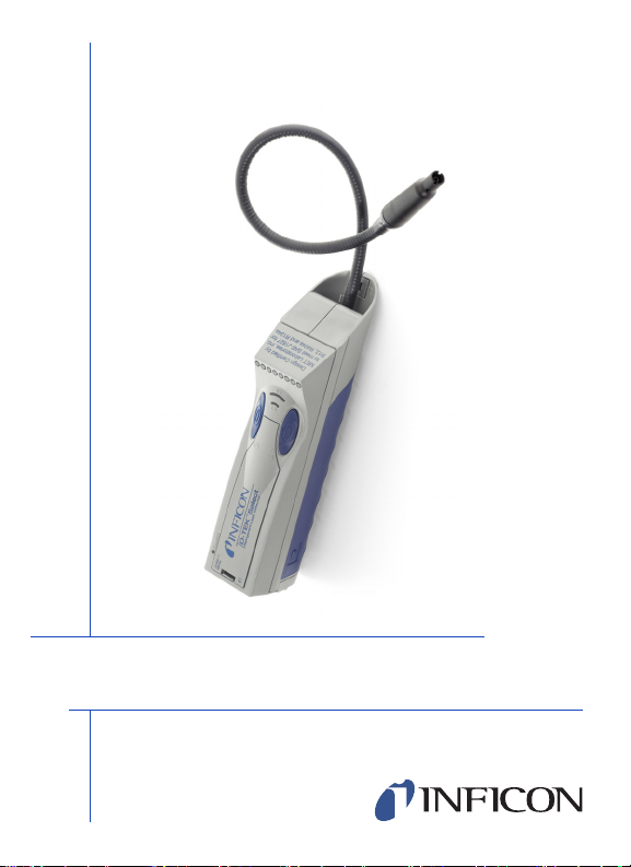
Thank you for buying the INFICON D-TEK Select
Green / Yellow
LEDs
High / Low
Sensitivity Switch
Power
Switch
Power Cell
Compartment
Filter
Cartridge
Flexible
Probe
Rubberized
Grip
Tip
Power
Jack
Headphone
Jack
High / Low
Indicators
Charge
Indicator
IR Cell
Access Door
Probe
Cap
Refrigerant Leak Detector!
With normal use, your D-TEK Select from INFICON will give you years of
trouble-free service.
To get the best performance from your D-TEK Select, please read this manual
carefully before you start using the instrument. If you have any questions or need
additional assistance, please call 800-344-3304. We’ll be happy to help you.
3
Page 4

Getting Started
WARNING
The D-TEK Select is shipped with the infrared cell and power stick installed. The
nickel/metal hydride batteries in the power stick are not yet charged. To charge
them, connect the cord of the AC power adapter to the power jack at the rear of
the instrument, and plug the adapter into the appropriate mains outlet. The battery
charging light (rear left side) will flash when the detector is charging, changing to
steady illumination when the power stick is charged. Allow 10 hours for the full
charge.
NOTE: You should expect approximately 6.5 hours of operation from a fully
charged power stick. The D-TEK Select will operate off the AC power
adapter. Connecting the supplied AC power adapter will allow operation
of the detector while the power stick charges.
Using Your INFICON D-TEK Select
Do not operate this instrument in the presence of gasoline,
natural gas, propane, or in other combustive atmospheres.
Using the D-TEK Select is simple. Press the power switch once to turn the
detector ON. The green ON LED will illuminate, and the yellow LEDs will
illuminate from left to right in a scrolling fashion while the infrared cell warms up
(approximately 60 seconds). When the detector is warmed up and ready for use,
the yellow LEDs extinguish and you will hear a steady beeping.
The D-TEK Select provides similar responses to all CFC’s, HCFC’s, HFC’s and
refrigerant blends (i.e., R-404A, R407C, R-410A) as well as SF6. There is no
need to select the refrigerant you’re working with.
NOTE: The D-TEK Select does not detect R-11 due to the particular physical
properties of this refrigerant.
4
Page 5

Headphone sets may be used with the D-TEK Select. When the headphones are
WARNING
plugged into the detector, the audio signal will only be heard through the headset.
Only use headphone sets supplied by INFICON, PN 032-0430.
serious hearing damage may occur if other headphone sets are
used.
Finding Leaks
1. Place the tip of the leak-detector probe as close as possible to the site of the
suspected leak. Try to position the probe within 1/4 inch (0.5 cm) of the possible
leak source.
2. Slowly (approximately 1 - 2 inches (2.5 - 5 cm) per second) move the probe past
each possible leak point.
NOTE: It is important to move the tip of the probe past the leak to get a
correct reading. The D-TEK Select only responds to changes in
concentration of the refrigerant from the leak. Moving the probe
permits the instrument to respond properly to these changes.
3. When the instrument detects a leak source, its yellow LEDs will illuminate and
it will beep rapdily.
4. When the D-TEK Select signals a leak, pull the probe away from the leak for a
moment, then bring it back to pinpoint the location.
5. If the concentration of the refrigerant gas is high, press the sensitivity switch to
change to the LOW sensitivity setting. The LOW sensitivity setting helps find the
exact site when a leak is large.
6. Once you have isolated the leak source, return the sensitivity setting to HIGH
to continue using the D-TEK Select.
7. When you are done leak checking, press the Power switch to turn the D-TEK
Select OFF.
5
Page 6

Using the Manual Zero Mode
The D-TEK Select's automatic suppression of background contamination can be
disabled, allowing for a continuous display of a leak without "zeroing it out". When
the D-TEK Select is set in the manual zero mode, the technician may manually
reset or zero the detector.
To initialize this function, press and hold the HI/LO switch for 5 seconds. The "HI"
sensitivity indicator will flash to alert the user the detector is in manual zero mode.
Increases in concentrations of refrigerants will be displayed by the illumination of
the yellow LEDS. For best test results, allow the D-TEK Select to warm up for
5 - 10 minutes before engaging manual zero mode.
To "zero" the D-TEK Select, press the HI/LO switch once. Both the HI and LO
sensitivity indictors will flash for a few seconds while the detector measures and
sets a new background base level. Any increase in concentrations of refrigerant
above this base level will be displayed.
To turn off the manual zero mode, press and hold the HL/LO switch until the HI
sensitivity indicator becomes steady.
NOTE: When the D-TEK Select is turned on, it will always default to the
automatic zeroing mode.
6
Page 7

Recharging the Power Stick
WARNING
A fully charged power stick should provide power for approximately 6.5 hours of
continuous operation. When the battery is fully depleted, the D-TEK Select will
shut down. To show the battery is depleted, the green ON LED, the last yellow
leak LED and the amber battery charging LED will flash. Recharge the D-TEK
Select by connecting the supplied AC power adapter, or using the cigarette lighter
adapter.
NOTE: The D-TEK Select does not need to be fully charged to operate nor fully
discharged before recharging.
Do not attach any other power cords to the D-TEK select’s power
jack except the AC power adapter and DC cords designed for this
instrument.
The battery charging indicator (rear left side) will flash when the power stick is
charging, changing to steady illumination when the power stick is fully charged.
Allow 10 hours for a full charge.
The D-TEK Select will operate off the AC power adapter. Connecting the supplied
AC power adapter will allow operation of the detector while the power stick
charges.
7
Page 8

Changing the Filter Cartridge
CAUTION
The D-TEK Select utilizes a specially designed filter cartridge that fits into a
protective cap. The filter cartridge should be changed when it appears dirty or
when substances trapped in the filter cartridge seem to be affecting the sensitivity
of the D-TEK Select.
NOTE: Water or oil will not penetrate the filter material but will prevent airflow
through the filter and affect sensitivity.
Turn off the D-TEK Select and hold the probe with the filter tip
pointing down when removing the filter cap.
To change the filter cartridge, twist off the protective cap. Remove and dispose of
the used filter cartridge. Do not allow any moisture or dust to get into the probe.
Do not disassemble or attempt to clean the material inside the filter cartridge, as it
can be damaged when handled. Slide a new filter cartridge into the cap. Twist the
cap with the new filter cartridge onto the probe base until it is tight.
NOTE: It is very important that you operate the D-TEK Select with a filter
cartridge installed at all times. Failure to do so could damage the leak
detector's components.
8
Page 9

Changing the Infrared Cell
WARNING
Components may be hot. Turn off detector and disconnect power
adapter cord before removing the infrared cell door.
The D-TEK Select’s infrared cell (IR cell) is located in the body of the detector.
The IR cell is a complete assembly consisting of a metal tube, connectors and
electronic components. The IR cell is not designed to be taken apart. Doing so will
destroy the cell. This specialized IR cell will operate for about 1000 hours.
The D-TEK Select will flash all the yellow leak LEDs when the IR cell has reached
the end of its useful life. To replace the IR cell:
1. Locate on the top cover (at the rear of the detector) the latch for the IR cell door.
2. Using a small screwdriver, pull the latch forward and remove the door.
3. Grasp the IR cell according to the directions printed on its label.
Pull it straight out so both ends are released at the same time.
4. Remove the replacement IR cell from the protective package.
5. Carefully align the male leads and air tubes on the IR cell with the connectors
mounted on the circuit board. Insert the leads into the sockets and push the IR
cell straight down.
NOTE: Ensure the lead connectors on the IR cell ends are not bent and the cell
is seated tightly.
9
Page 10

Removing/Replacing the Power Stick
The D-TEK Select uses a pre-assembled power stick.
Remove the battery compartment door on the back of the D-TEK Select by
pressing on both release buttons on the grip and pulling the door straight out. The
power stick is connected to the PCB board via a miniature electrical connector.
Disengage the connector and slide the power stick out of the D-TEK Select.
Slide the new stick into the D-TEK Select and push the miniature connector on the
power stick into the mating half on the PCB board. Do not bend the PCB board’s
connector away from the board. Once the power stick is in place, close the battery
compartment by aligning the two tabs and sliding the door straight in until it
latches. Ensure the wire leads on the power stick are not pinched in the door.
Allow 10 hours to fully charge the new power stick.
NOTE: If the D-TEK Select does not power up after the power stick is replaced,
check that the key connector on the power stick is mated properly to the
connector on the circuit board. Reverse the connection if necessary and
power up again. If the Hi/Lo indicators flash in a rapid, alternating manner
when the AC adapter is connected, the power stick is installed
backwards.
10
Page 11

Replacement Parts and Accessories
Replacement parts and accessories for your D-TEK Select are available through
the same dealer from whom you bought the instrument.
Molded plastic storage case. . . . . . . . . . . . . . . . . . . . . . . . . . . . . . . . . 712-702-G1
Headphones . . . . . . . . . . . . . . . . . . . . . . . . . . . . . . . . . . . . . . . . . . . . . 032-0430
12-volt cord with cigarette-lighter plug, 3.7 m (12 ft.). . . . . . . . . . . . . . 703-055-P1
120-volt mains adapter and cord, 1.8 m (6 ft.) . . . . . . . . . . . . . . . . . . 033-0019-G1
230-volt (Euro plug) mains adapter and cord, 1.8 m (6 ft.). . . . . . . . . 033-0020-G1
230-volt (UK plug) mains adapter and cord, 1.8 m (6 ft.). . . . . . . . . . 033-0022-G1
100-volt mains adapter and cord, 1.8 m (6 ft.) . . . . . . . . . . . . . . . . . . 033-0018-G1
230-volt (Australia) mains adapter and cord, 1.8 m (6 ft.) . . . . . . . . . 033-0035-G1
Power Stick . . . . . . . . . . . . . . . . . . . . . . . . . . . . . . . . . . . . . . . . . . . . . 712-700-G1
Replacement infrared cell . . . . . . . . . . . . . . . . . . . . . . . . . . . . . . . . . . 712-701-G1
Filter Cartridges, package of 5 . . . . . . . . . . . . . . . . . . . . . . . . . . . . . . . 712-707-G1
Replacement Probe Cap . . . . . . . . . . . . . . . . . . . . . . . . . . . . . . . . . . . 712-705-G1
Specifications
Usage. . . . . . . . . . . . . . . . . . . . . . . . . . . . . . . . . . . . . . . . . . . . . Indoor or Outdoor
Minimum sensitivity to R12 and R134a . . . . . . . . . . . . . . . . . . . . . . . . . . . . 3 g/yr)
Input voltage range . . . . . . . . . . . . . . . . . . . . . . . . . . . . . . . . . . . . .12 to 16 V (dc)
Input current . . . . . . . . . . . . . . . . . . . . . . . . . . . . . . . . . . . . . . . . . . . . 500 mA Max.
Operating and charging temperature range* . . . . . . . . . . . . . . . . -20 °C to +50 °C
Storage temperature range . . . . . . . . . . . . . . . . . . . . . . . . . . . . . -20 °C to +60 °C
Humidity . . . . . . . . . . . . . . . . . . . . . . . . . . . . . . . . . . . . . . . . . . . 95% RH NC Max.
Altitude . . . . . . . . . . . . . . . . . . . . . . . . . . . . . . . . . . . . . . . . . . . . . 2000 m (6500 ft.)
Pollution degree . . . . . . . . . . . . . . . . . . . . . . . . . . . . . . . . . . . . . . . . . . . . . . . . . . 2
Overvoltage category . . . . . . . . . . . . . . . . . . . . . . . . . . . . . . . . . . . . . . . . . . . . . . 2
Weight (with power cells) . . . . . . . . . . . . . . . . . . . . . . . . . . . . . . . 0.58 kg (1.28 lb.)
*May be operated for a limited time in lower temperature environments
( -4°F to 122 °F)
(-4°F to +140 °F)
11
Page 12

Troubleshooting Guide
Problem Cause Remedy
1) All yellow lights
flashing together.
2) Will not detect
refrigerant.
3) After warm up
sequence the green,
the last yellow and the
amber charging LEDs
flash.
4) Pump is not
working.
1a) IR sensor cell has
become unseated.
1b) IR sensor cell has
failed.
2a) Unit may not be
warmed up and
ready to use.
2d) Battery may be
dead.
2c) Filter cartridge
may be clogged,
preventing air and
refrigerant from
passing into IR cell.
2b) Pump may have
failed.
2e) User may be
working with R-11.
3a) Battery needs
recharging.
3b) Power stick has
failed.
4a) Pump has failed. 4a) See 2d.
1a) Remove sensor access
door and push both ends of
sensor down. (Do not
remove/reinsert sensor cell.)
Restart unit and examine.
1b) Replace with new sensor,
part number 712-701-G1.
2a) If yellow lights are
scrolling, wait 90 seconds to
see if the unit starts to beep
and the lights stop scrolling. If
not, contact INFICON.
2d) See #3 below.
2c) Replace used filter
cartridge with a new one.
2b) You should hear the pump
running after the warm up
sequence is completed.
VERIFY it is not a low battery
condition (see #3). If not,
contact INFICON.
2e) This refrigerant is only
detectable if the leak is quite
large.
3a) Charge battery for 10-12
hours.
3b) Replace power stick with
part #712-700-G1.
Page 13

Problem Cause Remedy
5) Unit does not
power up. Hi/Lo
indicators flash in a
rapid, alternating
manner when AC
adapter is connected.
5a) Power
stick/battery has been
connected in reverse.
5a) Reverse the battery's
connection and power unit up
again.
Warranty and Liability-Limitation
INFICON warrants your D-TEK Select Refrigerant Leak Detector to be free from
defects of materials or workmanship for two years from the date of purchase.
INFICON does not warrant items that deteriorate under normal use,
including power stick, infrared cell and filters. In addition, INFICON does not
warrant any instrument that has been subjected to misuse, negligence, or
accident, or has been repaired or altered by anyone other than INFICON.
INFICON liability is limited to instruments returned to INFICON, transportation
prepaid, not later than thirty (30) days after the warranty period expires, and which
INFICON judges to have malfunctioned because of defective materials or
workmanship. INFICON liability is limited to, at its option, repairing or replacing
the defective instrument or part.
This warranty is in lieu of all other warranties, express or implied, whether of
MERCHANTABILITY or of FITNESS FOR A PARTICULAR PURPOSE or
otherwise. All such other warranties are expressly disclaimed. INFICON shall
have no liability in excess of the price paid to INFICON for the instrument plus
return transportation charges prepaid. INFICON shall have no liability for any
incidental or consequential damages. All such liabilities are EXCLUDED.
13
Page 14

Return Materials Authorization Procedure
All instruments and parts returned to INFICON for repair or credit must be
properly packaged, insured, shipped transportation charges prepaid, and must
have a Return Material Authorization (RMA) number issued before the material is
returned. The RMA number is to be marked on all shipping labels and packing
slips. Please see your INFICON distributor for assistance. If you have any
questions contact us at 800-344-3304.
14
Page 15

15
Page 16

TWO TECHNOLOGY PLACE
EAST SYRACUSE, NY 13057-9714 USA
Phone: +1.800.344.3304
Fax: +315.437.3803
E-Mail: service.tools@inficon.com
www.inficonservicetools.com
074-392-P1L
 Loading...