

Page 1
OPERATING MANUAL
®
Cygnus
Thin Film Deposition Monitor
IPN 074-379-P1K
Page 2

Page 3

OPERATING MANUAL
®
Cygnus
Thin Film Deposition Monitor
IPN 074-379-P1K
www.inficon.com reachus@inficon.com
Due to our continuing program of product improvements, specifications are subject to change without notice.
©2004 INFICON
Page 4

Trademarks
The trademarks of the products mentioned in this Operating Manual are held by the companies that
produce them.
INFICON® and Cygnus® are trademarks of INFICON Inc.
Windows®, Windows 95® and Microsoft® are registered trademarks of Microsoft Corporation.
CAJON® is a registered trademark of Swagelok, Co.
All other brand and product names are trademarks or registered trademarks of their respective companies.
The information contained in this Operating Manual is believed to be accurate and reliable. However, INFICON
assumes no responsibility for its use and shall not be liable for any special, incidental, or consequential
damages related to the use of this product.
Due to our continuing program of product improvements, specifications are subject to change without notice.
©2004 All rights reserved.
Reproduction or adaptation of any part of this document without permission is unlawful.
Page 5

DECLARATION
OF
CONFORMITY
This is to certify that this equipment, designed and manufactured by:
INFICON Inc.
Two Technology Place
East Syracuse, NY 13057
USA
meets the essential safety requirements of the European Union and is placed on the
market accordingly. It has been constructed in accordance with good engineering
practice in safety matters in force in the Community and does not endanger the safety
of persons, domestic animals or property when properly installed and maintained and
used in applications for which it was made.
Equipment Description: Cygnus Thin Film Deposition Controllers, including
Oscillators and Crystal Sensors as properly installed.
Applicable Directives: 73/23/EEC as amended by 93/68/EEC
89/336/EEC as amended by 93/68/EEC
Applicable Standards: EN 61010-1:2001
EN 61326:1997 (Industrial Use)
EN 61000-3-2:1995/A14:2000
EN 61000-3-3:1995
CE Implementation Date: August 22, 2003
Authorized Representative: Gary W. Lewis
Vice President - Quality Assurance
INFICON Inc.
ANY QUESTIONS RELATIVE TO THIS DECLARATION OR TO THE SAFETY OF LEYBOLD INFICON'S PRODUCTS SHOULD BE
DIRECTED, IN WRITING, TO THE QUALITY ASSURANCE DEPARTMENT AT THE ABOVE ADDRESS.
01-22-04
Page 6

Page 7

Warranty
WARRANTY AND LIABILITY - LIMITATION: Seller warrants the products
manufactured by it, or by an affiliated company and sold by it, and described on
the reverse hereof, to be, for the period of warranty coverage specified below, free
from defects of materials or workmanship under normal proper use and service.
The period of warranty coverage is specified for the respective products in the
respective Seller instruction manuals for those products but shall not be less than
two (2) years from the date of shipment thereof by Seller. Seller's liability under
this warranty is limited to such of the above products or parts thereof as are
returned, transportation prepaid, to Seller's plant, not later than thirty (30) days
after the expiration of the period of warranty coverage in respect thereof and are
found by Seller's examination to have failed to function properly because of
defective workmanship or materials and not because of improper installation or
misuse and is limited to, at Seller's election, either (a) repairing and returning the
product or part thereof, or (b) furnishing a replacement product or part thereof,
transportation prepaid by Seller in either case. In the event Buyer discovers or
learns that a product does not conform to warranty, Buyer shall immediately notify
Seller in writing of such non-conformity, specifying in reasonable detail the nature
of such non-conformity. If Seller is not provided with such written notification,
Seller shall not be liable for any further damages which could have been avoided if
Seller had been provided with immediate written notification.
THIS WARRANTY IS MADE AND ACCEPTED IN LIEU OF ALL OTHER
WARRANTIES, EXPRESS OR IMPLIED, WHETHER OF MERCHANTABILITY OR
OF FITNESS FOR A PARTICULAR PURPOSE OR OTHERWISE, AS BUYER'S
EXCLUSIVE REMEDY FOR ANY DEFECTS IN THE PRODUCTS TO BE SOLD
HEREUNDER. All other obligations and liabilities of Seller, whether in contract or
tort (including negligence) or otherwise, are expressly EXCLUDED. In no event
shall Seller be liable for any costs, expenses or damages, whether direct or
indirect, special, incidental, consequential, or other, on any claim of any defective
product, in excess of the price paid by Buyer for the product plus return
transportation charges prepaid.
No warranty is made by Seller of any Seller product which has been installed,
used or operated contrary to Seller's written instruction manual or which has been
subjected to misuse, negligence or accident or has been repaired or altered by
anyone other than Seller or which has been used in a manner or for a purpose for
which the Seller product was not designed nor against any defects due to plans or
instructions supplied to Seller by or for Buyer.
This manual is intended for private use by INFICON® Inc. and its customers.
Contact INFICON before reproducing its contents.
NOTE: These instructions do not provide for every contingency that may arise in
connection with the installation, operation or maintenance of this equipment.
Should you require further assistance, please contact INFICON.
www.inficon.com reachus@inficon.com
Page 8

Page 9

Cygnus Operating Manual
Table Of Contents
Chapter 1
Introduction and Specifications
1.1 Introduction. . . . . . . . . . . . . . . . . . . . . . . . . . . . . . . . . . . . . . . . . . . . . . . . . . 1-1
1.1.1 Related Manuals. . . . . . . . . . . . . . . . . . . . . . . . . . . . . . . . . . . . . . . . . . . . . .1-1
1.2 Instrument Safety . . . . . . . . . . . . . . . . . . . . . . . . . . . . . . . . . . . . . . . . . . . . . 1-2
1.2.1 Definition of Notes, Cautions and Warnings. . . . . . . . . . . . . . . . . . . . . . . . . 1-2
1.2.2 General Safety Information. . . . . . . . . . . . . . . . . . . . . . . . . . . . . . . . . . . . . .1-3
1.2.3 Earth Ground . . . . . . . . . . . . . . . . . . . . . . . . . . . . . . . . . . . . . . . . . . . . . . . .1-4
1.2.4 Main Power Connection . . . . . . . . . . . . . . . . . . . . . . . . . . . . . . . . . . . . . . . . 1-5
1.3 How To Contact Customer Support . . . . . . . . . . . . . . . . . . . . . . . . . . . . . . .1-6
1.3.1 Returning Your Cygnus to INFICON . . . . . . . . . . . . . . . . . . . . . . . . . . . . . . 1-6
1.4 Cygnus Specifications . . . . . . . . . . . . . . . . . . . . . . . . . . . . . . . . . . . . . . . . .1-7
1.4.1 Measurement . . . . . . . . . . . . . . . . . . . . . . . . . . . . . . . . . . . . . . . . . . . . . . . .1-7
1.4.2 Screens and Parameters . . . . . . . . . . . . . . . . . . . . . . . . . . . . . . . . . . . . . . . 1-7
1.4.2.1 Instrument Set Up Parameters. . . . . . . . . . . . . . . . . . . . . . . . . . . . . . . . . . .1-8
1.4.2.2 Set Up Parameters for Each Source . . . . . . . . . . . . . . . . . . . . . . . . . . . . . .1-8
1.4.3 User Interface. . . . . . . . . . . . . . . . . . . . . . . . . . . . . . . . . . . . . . . . . . . . . . .1-11
1.4.4 Display . . . . . . . . . . . . . . . . . . . . . . . . . . . . . . . . . . . . . . . . . . . . . . . . . . . . 1-12
1.4.5 Source / Recorder Outputs. . . . . . . . . . . . . . . . . . . . . . . . . . . . . . . . . . . . .1-13
1.4.6 Logic Processing . . . . . . . . . . . . . . . . . . . . . . . . . . . . . . . . . . . . . . . . . . . .1-14
1.4.7 Relays / Inputs . . . . . . . . . . . . . . . . . . . . . . . . . . . . . . . . . . . . . . . . . . . . . . 1-14
1.4.8 Remote Communications . . . . . . . . . . . . . . . . . . . . . . . . . . . . . . . . . . . . . .1-15
1.4.9 Accessories . . . . . . . . . . . . . . . . . . . . . . . . . . . . . . . . . . . . . . . . . . . . . . . .1-15
1.4.10 Power . . . . . . . . . . . . . . . . . . . . . . . . . . . . . . . . . . . . . . . . . . . . . . . . . . . . . 1-15
1.4.11 Operating Environment. . . . . . . . . . . . . . . . . . . . . . . . . . . . . . . . . . . . . . . . 1-16
IPN 074-379-P1K
1.4.12 Storage Temperature . . . . . . . . . . . . . . . . . . . . . . . . . . . . . . . . . . . . . . . . . 1-16
1.4.13 Warm Up Period . . . . . . . . . . . . . . . . . . . . . . . . . . . . . . . . . . . . . . . . . . . . .1-16
1.4.14 Size. . . . . . . . . . . . . . . . . . . . . . . . . . . . . . . . . . . . . . . . . . . . . . . . . . . . . . .1-16
1.4.15 Connector Clearance Requirements . . . . . . . . . . . . . . . . . . . . . . . . . . . . . 1-16
1.4.16 Weight . . . . . . . . . . . . . . . . . . . . . . . . . . . . . . . . . . . . . . . . . . . . . . . . . . . . 1-16
1.4.17 Cleaning . . . . . . . . . . . . . . . . . . . . . . . . . . . . . . . . . . . . . . . . . . . . . . . . . . . 1-16
1.5 Unpacking and Inspection . . . . . . . . . . . . . . . . . . . . . . . . . . . . . . . . . . . . .1-17
1.6 Parts and Options Overview. . . . . . . . . . . . . . . . . . . . . . . . . . . . . . . . . . . .1-17
1.6.1 Base Configurations . . . . . . . . . . . . . . . . . . . . . . . . . . . . . . . . . . . . . . . . . .1-17
1.6.2 Pre-Installed Options or Spares . . . . . . . . . . . . . . . . . . . . . . . . . . . . . . . . . 1-18
1.6.3 Oscillator Packages, Optional Accessories, and Sensors . . . . . . . . . . . . . 1-18
1.7 Initial Power-On Verification . . . . . . . . . . . . . . . . . . . . . . . . . . . . . . . . . . . .1-20
TOC - 1
Page 10

Cygnus Operating Manual
Chapter 2
Operation
2.1 Front Panel Controls . . . . . . . . . . . . . . . . . . . . . . . . . . . . . . . . . . . . . . . . . . 2-1
2.2 Rear Panel Interfaces. . . . . . . . . . . . . . . . . . . . . . . . . . . . . . . . . . . . . . . . . . 2-3
2.3 Displays . . . . . . . . . . . . . . . . . . . . . . . . . . . . . . . . . . . . . . . . . . . . . . . . . . . . 2-4
2.3.1 ALL CHANNELS Display . . . . . . . . . . . . . . . . . . . . . . . . . . . . . . . . . . . . . . . 2-5
2.3.1.1 GENERAL PARAMETERS Display . . . . . . . . . . . . . . . . . . . . . . . . . . . . . . . 2-8
2.3.1.2 General MAINTENANCE Display. . . . . . . . . . . . . . . . . . . . . . . . . . . . . . . . . 2-9
2.3.1.2.1 All Channels Sensor MAINTENANCE Display. . . . . . . . . . . . . . . . . . . . . . 2-11
2.3.1.3 CHANNEL Display . . . . . . . . . . . . . . . . . . . . . . . . . . . . . . . . . . . . . . . . . . . 2-12
2.3.1.3.1 Channel Parameters Display . . . . . . . . . . . . . . . . . . . . . . . . . . . . . . . . . . . 2-16
2.3.1.3.1.1 HARDWARE PROCESS Display. . . . . . . . . . . . . . . . . . . . . . . . . . . . . . . . 2-17
2.3.1.3.2 Channel SENSOR MAINTENANCE Display . . . . . . . . . . . . . . . . . . . . . . . 2-17
2.3.1.3.2.1 Channel SOURCE MAINTENANCE Display . . . . . . . . . . . . . . . . . . . . . . . 2-20
2.4 Crystal Life, Starting Frequency and Activity . . . . . . . . . . . . . . . . . . . . . . . 2-21
2.5 Defining a Process . . . . . . . . . . . . . . . . . . . . . . . . . . . . . . . . . . . . . . . . . . . 2-22
2.5.1 Executing a Process. . . . . . . . . . . . . . . . . . . . . . . . . . . . . . . . . . . . . . . . . . 2-22
2.6 State Descriptions . . . . . . . . . . . . . . . . . . . . . . . . . . . . . . . . . . . . . . . . . . . 2-23
2.7 Special Features . . . . . . . . . . . . . . . . . . . . . . . . . . . . . . . . . . . . . . . . . . . . 2-24
2.7.1 Crystal Switching . . . . . . . . . . . . . . . . . . . . . . . . . . . . . . . . . . . . . . . . . . . . 2-24
2.7.2 Rotary Sensor Crystal Switching . . . . . . . . . . . . . . . . . . . . . . . . . . . . . . . . 2-25
2.7.3 Source/Crucible Selection . . . . . . . . . . . . . . . . . . . . . . . . . . . . . . . . . . . . . 2-26
2.7.3.1 Example: Programming Turret Source Crucible Selection. . . . . . . . . . . . . 2-26
2.7.4 Hand-Held Controller . . . . . . . . . . . . . . . . . . . . . . . . . . . . . . . . . . . . . . . . . 2-28
2.7.5 Test Mode . . . . . . . . . . . . . . . . . . . . . . . . . . . . . . . . . . . . . . . . . . . . . . . . . 2-29
2.7.6 Floppy Disk (Optional) . . . . . . . . . . . . . . . . . . . . . . . . . . . . . . . . . . . . . . . . 2-29
2.7.7 Lock Codes . . . . . . . . . . . . . . . . . . . . . . . . . . . . . . . . . . . . . . . . . . . . . . . . 2-30
2.7.8 Datalog. . . . . . . . . . . . . . . . . . . . . . . . . . . . . . . . . . . . . . . . . . . . . . . . . . . . 2-30
2.7.9 Auto Soak 2 . . . . . . . . . . . . . . . . . . . . . . . . . . . . . . . . . . . . . . . . . . . . . . . . 2-32
IPN 074-379-P1K
Chapter 3
TOC - 2
Channel Parameters
3.1 Introduction. . . . . . . . . . . . . . . . . . . . . . . . . . . . . . . . . . . . . . . . . . . . . . . . . . 3-1
3.2 Channel Parameters . . . . . . . . . . . . . . . . . . . . . . . . . . . . . . . . . . . . . . . . . . 3-2
3.2.1 Channel Parameter Definitions . . . . . . . . . . . . . . . . . . . . . . . . . . . . . . . . . . 3-2
3.3 Channel Hardware Parameters . . . . . . . . . . . . . . . . . . . . . . . . . . . . . . . . . 3-12
3.3.1 Channel Hardware Parameters Definition . . . . . . . . . . . . . . . . . . . . . . . . . 3-12
Page 11

Cygnus Operating Manual
Chapter 4
General Parameters
4.1 Introduction. . . . . . . . . . . . . . . . . . . . . . . . . . . . . . . . . . . . . . . . . . . . . . . . . . 4-1
4.2 General Parameter Display . . . . . . . . . . . . . . . . . . . . . . . . . . . . . . . . . . . . . 4-2
4.3 General Parameters Definition . . . . . . . . . . . . . . . . . . . . . . . . . . . . . . . . . . .4-3
4.4 Logic Directory Set Up . . . . . . . . . . . . . . . . . . . . . . . . . . . . . . . . . . . . . . . . .4-5
4.4.1 Logic Statement Overview . . . . . . . . . . . . . . . . . . . . . . . . . . . . . . . . . . . . . .4-5
4.4.2 Editing Logic Statements . . . . . . . . . . . . . . . . . . . . . . . . . . . . . . . . . . . . . . . 4-6
4.4.2.1 Logic Statement Directory . . . . . . . . . . . . . . . . . . . . . . . . . . . . . . . . . . . . . .4-7
4.4.2.2 Logic Statements . . . . . . . . . . . . . . . . . . . . . . . . . . . . . . . . . . . . . . . . . . . . .4-7
4.4.2.3 Logic Statement Event Editing . . . . . . . . . . . . . . . . . . . . . . . . . . . . . . . . . . . 4-8
4.4.2.3.1 Event Definitions (IF) . . . . . . . . . . . . . . . . . . . . . . . . . . . . . . . . . . . . . . . . .4-10
4.4.2.4 Logic Statement Action Editing. . . . . . . . . . . . . . . . . . . . . . . . . . . . . . . . . .4-13
4.4.2.4.1 Action Definitions (THEN). . . . . . . . . . . . . . . . . . . . . . . . . . . . . . . . . . . . . .4-14
4.5 Counters Timers. . . . . . . . . . . . . . . . . . . . . . . . . . . . . . . . . . . . . . . . . . . . . 4-16
4.6 I/O Map. . . . . . . . . . . . . . . . . . . . . . . . . . . . . . . . . . . . . . . . . . . . . . . . . . . . 4-17
4.7 Floppy Disk. . . . . . . . . . . . . . . . . . . . . . . . . . . . . . . . . . . . . . . . . . . . . . . . .4-19
Chapter 5
Remote Communications
5.1 Remote Communications Overview . . . . . . . . . . . . . . . . . . . . . . . . . . . . . . . 5-1
5.2 Physical Connections . . . . . . . . . . . . . . . . . . . . . . . . . . . . . . . . . . . . . . . . . .5-1
5.2.1 RS232C Serial Port . . . . . . . . . . . . . . . . . . . . . . . . . . . . . . . . . . . . . . . . . . .5-1
5.2.2 IEEE488 Port . . . . . . . . . . . . . . . . . . . . . . . . . . . . . . . . . . . . . . . . . . . . . . . . 5-3
5.3 Message Protocols. . . . . . . . . . . . . . . . . . . . . . . . . . . . . . . . . . . . . . . . . . . . 5-4
5.3.1 INFICON Cygnus Message Formats . . . . . . . . . . . . . . . . . . . . . . . . . . . . . .5-4
5.3.2 Basic Protocol. . . . . . . . . . . . . . . . . . . . . . . . . . . . . . . . . . . . . . . . . . . . . . . .5-4
5.3.2.1 Command Packet (Host to Instrument Message). . . . . . . . . . . . . . . . . . . . .5-4
IPN 074-379-P1K
5.3.2.2 Response Packet (Instrument to Host Message). . . . . . . . . . . . . . . . . . . . . 5-6
5.4 Cygnus Communication Commands . . . . . . . . . . . . . . . . . . . . . . . . . . . . . . 5-7
5.4.1 ECHO Command . . . . . . . . . . . . . . . . . . . . . . . . . . . . . . . . . . . . . . . . . . . . .5-7
5.4.2 HELLO Command . . . . . . . . . . . . . . . . . . . . . . . . . . . . . . . . . . . . . . . . . . . .5-8
5.4.3 Parameter Commands . . . . . . . . . . . . . . . . . . . . . . . . . . . . . . . . . . . . . . . . . 5-9
5.4.3.1 All Parameters . . . . . . . . . . . . . . . . . . . . . . . . . . . . . . . . . . . . . . . . . . . . . . .5-9
5.4.3.1.1 Query All Parameters . . . . . . . . . . . . . . . . . . . . . . . . . . . . . . . . . . . . . . . . . .5-9
5.4.3.1.2 Update All Parameters . . . . . . . . . . . . . . . . . . . . . . . . . . . . . . . . . . . . . . . . 5-10
5.4.3.2 Channel Parameters. . . . . . . . . . . . . . . . . . . . . . . . . . . . . . . . . . . . . . . . . .5-10
5.4.3.2.1 Query Channel Parameters . . . . . . . . . . . . . . . . . . . . . . . . . . . . . . . . . . . . 5-10
5.4.3.2.2 Update Channel Parameters . . . . . . . . . . . . . . . . . . . . . . . . . . . . . . . . . . .5-11
TOC - 3
Page 12

Cygnus Operating Manual
5.4.3.3 General Parameters. . . . . . . . . . . . . . . . . . . . . . . . . . . . . . . . . . . . . . . . . . 5-16
5.4.3.3.1 Query General Parameters . . . . . . . . . . . . . . . . . . . . . . . . . . . . . . . . . . . . 5-16
5.4.3.3.2 Update General Parameters . . . . . . . . . . . . . . . . . . . . . . . . . . . . . . . . . . . 5-16
5.4.3.4 Input Name Parameters . . . . . . . . . . . . . . . . . . . . . . . . . . . . . . . . . . . . . . . 5-18
5.4.3.4.1 Query Input Name . . . . . . . . . . . . . . . . . . . . . . . . . . . . . . . . . . . . . . . . . . . 5-18
5.4.3.4.2 Update Input Names . . . . . . . . . . . . . . . . . . . . . . . . . . . . . . . . . . . . . . . . . 5-18
5.4.3.5 Logic Statements Parameters . . . . . . . . . . . . . . . . . . . . . . . . . . . . . . . . . . 5-19
5.4.3.5.1 Query Logic Statements. . . . . . . . . . . . . . . . . . . . . . . . . . . . . . . . . . . . . . . 5-19
5.4.3.5.2 Update Logic Statements. . . . . . . . . . . . . . . . . . . . . . . . . . . . . . . . . . . . . . 5-19
5.4.3.6 Output Name Parameters . . . . . . . . . . . . . . . . . . . . . . . . . . . . . . . . . . . . . 5-23
5.4.3.6.1 Query Output Names . . . . . . . . . . . . . . . . . . . . . . . . . . . . . . . . . . . . . . . . . 5-23
5.4.3.6.2 Update Output Names . . . . . . . . . . . . . . . . . . . . . . . . . . . . . . . . . . . . . . . . 5-23
5.4.3.7 Type of Output Parameters . . . . . . . . . . . . . . . . . . . . . . . . . . . . . . . . . . . . 5-24
5.4.3.7.1 Query Output Type. . . . . . . . . . . . . . . . . . . . . . . . . . . . . . . . . . . . . . . . . . . 5-24
5.4.3.7.2 Update Output Type. . . . . . . . . . . . . . . . . . . . . . . . . . . . . . . . . . . . . . . . . . 5-24
5.4.4 STATUS Commands . . . . . . . . . . . . . . . . . . . . . . . . . . . . . . . . . . . . . . . . . 5-24
5.4.4.1 Status Channel Command . . . . . . . . . . . . . . . . . . . . . . . . . . . . . . . . . . . . . 5-25
5.4.4.2 Status General Commands . . . . . . . . . . . . . . . . . . . . . . . . . . . . . . . . . . . . 5-30
5.4.5 REMOTE Commands. . . . . . . . . . . . . . . . . . . . . . . . . . . . . . . . . . . . . . . . . 5-32
5.4.5.1 Remote Channel Action Commands . . . . . . . . . . . . . . . . . . . . . . . . . . . . . 5-33
5.4.5.2 Remote General Action Commands. . . . . . . . . . . . . . . . . . . . . . . . . . . . . . 5-35
5.4.6 Negative Response Error Codes . . . . . . . . . . . . . . . . . . . . . . . . . . . . . . . . 5-37
5.5 Sample Cygnus Commands. . . . . . . . . . . . . . . . . . . . . . . . . . . . . . . . . . . . 5-37
5.5.1 Remote Communications Example — Updating a
Channel’s Rate Parameter. . . . . . . . . . . . . . . . . . . . . . . . . . . . . . . . . . . . . 5-37
Chapter 6
Installation and Interfaces
6.1 Location Guidelines . . . . . . . . . . . . . . . . . . . . . . . . . . . . . . . . . . . . . . . . . . . 6-1
6.1.1 Sensor Types . . . . . . . . . . . . . . . . . . . . . . . . . . . . . . . . . . . . . . . . . . . . . . . . 6-1
6.1.2 Sensor Installation . . . . . . . . . . . . . . . . . . . . . . . . . . . . . . . . . . . . . . . . . . . . 6-3
6.1.3 Control Unit Installation . . . . . . . . . . . . . . . . . . . . . . . . . . . . . . . . . . . . . . . . 6-5
6.2 Avoiding Electrical Interference . . . . . . . . . . . . . . . . . . . . . . . . . . . . . . . . . . 6-5
6.2.1 Verifying/Establishing Earth Ground . . . . . . . . . . . . . . . . . . . . . . . . . . . . . . 6-5
6.2.2 Connections to Earth Ground. . . . . . . . . . . . . . . . . . . . . . . . . . . . . . . . . . . . 6-6
6.2.3 Minimizing Noise Pickup From External Cabling . . . . . . . . . . . . . . . . . . . . . 6-7
6.3 Connecting the Controller. . . . . . . . . . . . . . . . . . . . . . . . . . . . . . . . . . . . . . . 6-8
6.3.1 Verifying the Correct Input Voltage . . . . . . . . . . . . . . . . . . . . . . . . . . . . . . . 6-8
6.3.2 Voltage Selection . . . . . . . . . . . . . . . . . . . . . . . . . . . . . . . . . . . . . . . . . . . . . 6-9
IPN 074-379-P1K
TOC - 4
Page 13

Cygnus Operating Manual
6.3.3 Routing XIU Cables . . . . . . . . . . . . . . . . . . . . . . . . . . . . . . . . . . . . . . . . . . 6-10
6.3.4 Interface Cable Fabrication and Pin-Out . . . . . . . . . . . . . . . . . . . . . . . . . .6-10
6.3.4.1 Source Control Connection . . . . . . . . . . . . . . . . . . . . . . . . . . . . . . . . . . . .6-10
6.3.4.2 Input/Relay Module Connections . . . . . . . . . . . . . . . . . . . . . . . . . . . . . . . .6-11
6.3.4.3 RS-232C Communications. . . . . . . . . . . . . . . . . . . . . . . . . . . . . . . . . . . . .6-13
6.3.4.4 Isolated +24 V(dc) Supply . . . . . . . . . . . . . . . . . . . . . . . . . . . . . . . . . . . . . 6-14
6.3.4.5 Optional DAC Card. . . . . . . . . . . . . . . . . . . . . . . . . . . . . . . . . . . . . . . . . . . 6-15
Chapter 7
Calibration Procedures
7.1 Importance of Density, Tooling and Z-Ratio. . . . . . . . . . . . . . . . . . . . . . . . . 7-1
7.2 Determining Density . . . . . . . . . . . . . . . . . . . . . . . . . . . . . . . . . . . . . . . . . . .7-1
7.3 Determining Tooling . . . . . . . . . . . . . . . . . . . . . . . . . . . . . . . . . . . . . . . . . . . 7-2
7.4 Laboratory Determination of Z-Ratio . . . . . . . . . . . . . . . . . . . . . . . . . . . . . .7-3
7.5 Determining Cross Sensitivity Correction For Co-Deposition. . . . . . . . . . . .7-4
7.5.1 Procedure Overview. . . . . . . . . . . . . . . . . . . . . . . . . . . . . . . . . . . . . . . . . . . 7-5
7.5.2 Procedure Assumptions and Requirements. . . . . . . . . . . . . . . . . . . . . . . . . 7-5
7.5.3 Detailed Procedure. . . . . . . . . . . . . . . . . . . . . . . . . . . . . . . . . . . . . . . . . . . . 7-6
Chapter 8
Troubleshooting, Status and Error Messages
8.1 Status and Error Messages . . . . . . . . . . . . . . . . . . . . . . . . . . . . . . . . . . . . . 8-1
8.2 Troubleshooting Guide . . . . . . . . . . . . . . . . . . . . . . . . . . . . . . . . . . . . . . . . .8-8
8.2.1 Major Instrument Components and Assemblies. . . . . . . . . . . . . . . . . . . . . . 8-9
8.2.2 Troubleshooting the Instrument . . . . . . . . . . . . . . . . . . . . . . . . . . . . . . . . . 8-10
8.2.3 Troubleshooting Transducers/Sensors. . . . . . . . . . . . . . . . . . . . . . . . . . . .8-13
8.2.4 Troubleshooting Computer Communications . . . . . . . . . . . . . . . . . . . . . . .8-18
8.3 Replacing the Crystal . . . . . . . . . . . . . . . . . . . . . . . . . . . . . . . . . . . . . . . . . 8-20
8.3.1 Standard and Compact. . . . . . . . . . . . . . . . . . . . . . . . . . . . . . . . . . . . . . . .8-20
8.3.2 Shuttered and Dual Sensors . . . . . . . . . . . . . . . . . . . . . . . . . . . . . . . . . . . 8-21
IPN 074-379-P1K
8.3.3 Bakeable Sensor . . . . . . . . . . . . . . . . . . . . . . . . . . . . . . . . . . . . . . . . . . . .8-22
8.3.4 Sputtering Sensor. . . . . . . . . . . . . . . . . . . . . . . . . . . . . . . . . . . . . . . . . . . . 8-23
8.3.5 Crystal Snatcher. . . . . . . . . . . . . . . . . . . . . . . . . . . . . . . . . . . . . . . . . . . . .8-24
8.3.6 CrystalSix . . . . . . . . . . . . . . . . . . . . . . . . . . . . . . . . . . . . . . . . . . . . . . . . . . 8-24
8.3.7 Crystal12 . . . . . . . . . . . . . . . . . . . . . . . . . . . . . . . . . . . . . . . . . . . . . . . . . .8-24
8.4 Crystal Sensor Emulator IPN 760-601-G1 or 760-601-G2. . . . . . . . . . . . . 8-25
8.4.1 Diagnostic Procedures . . . . . . . . . . . . . . . . . . . . . . . . . . . . . . . . . . . . . . . .8-26
8.4.1.1 Measurement System Diagnostic Procedure . . . . . . . . . . . . . . . . . . . . . . .8-26
8.4.1.2 Feed-Through Or In-Vacuum Cable Diagnostic Procedure . . . . . . . . . . . .8-27
8.4.1.3 Sensor Head Or Monitor Crystal Diagnostic Procedure. . . . . . . . . . . . . . . 8-28
8.4.1.4 System Diagnostics Pass But Crystal Fail Message Remains. . . . . . . . . . 8-29
TOC - 5
Page 14

Cygnus Operating Manual
8.4.2 % XTAL Life . . . . . . . . . . . . . . . . . . . . . . . . . . . . . . . . . . . . . . . . . . . . . . . . 8-29
8.4.3 Sensor Cover Connection . . . . . . . . . . . . . . . . . . . . . . . . . . . . . . . . . . . . . 8-30
8.4.3.1 Compatible Sensor Heads . . . . . . . . . . . . . . . . . . . . . . . . . . . . . . . . . . . . . 8-30
8.4.3.2 Incompatible Sensor Heads . . . . . . . . . . . . . . . . . . . . . . . . . . . . . . . . . . . . 8-30
8.4.4 Specifications . . . . . . . . . . . . . . . . . . . . . . . . . . . . . . . . . . . . . . . . . . . . . . . 8-31
Chapter 9
Measurement and Control Theory
9.1 Basics. . . . . . . . . . . . . . . . . . . . . . . . . . . . . . . . . . . . . . . . . . . . . . . . . . . . . . 9-1
9.1.1 Monitor Crystals . . . . . . . . . . . . . . . . . . . . . . . . . . . . . . . . . . . . . . . . . . . . . . 9-2
9.1.2 Period Measurement Technique . . . . . . . . . . . . . . . . . . . . . . . . . . . . . . . . . 9-4
9.1.3 Z-Match Technique . . . . . . . . . . . . . . . . . . . . . . . . . . . . . . . . . . . . . . . . . . . 9-5
9.1.4 Active Oscillator . . . . . . . . . . . . . . . . . . . . . . . . . . . . . . . . . . . . . . . . . . . . . . 9-6
9.1.5 ModeLock Oscillator. . . . . . . . . . . . . . . . . . . . . . . . . . . . . . . . . . . . . . . . . . . 9-7
9.1.6 Auto Z-Match Theory . . . . . . . . . . . . . . . . . . . . . . . . . . . . . . . . . . . . . . . . . . 9-9
9.1.7 Control Loop Theory. . . . . . . . . . . . . . . . . . . . . . . . . . . . . . . . . . . . . . . . . . 9-11
Appendix A
Index
Material Table
IPN 074-379-P1K
TOC - 6
Page 15

1.1 Introduction
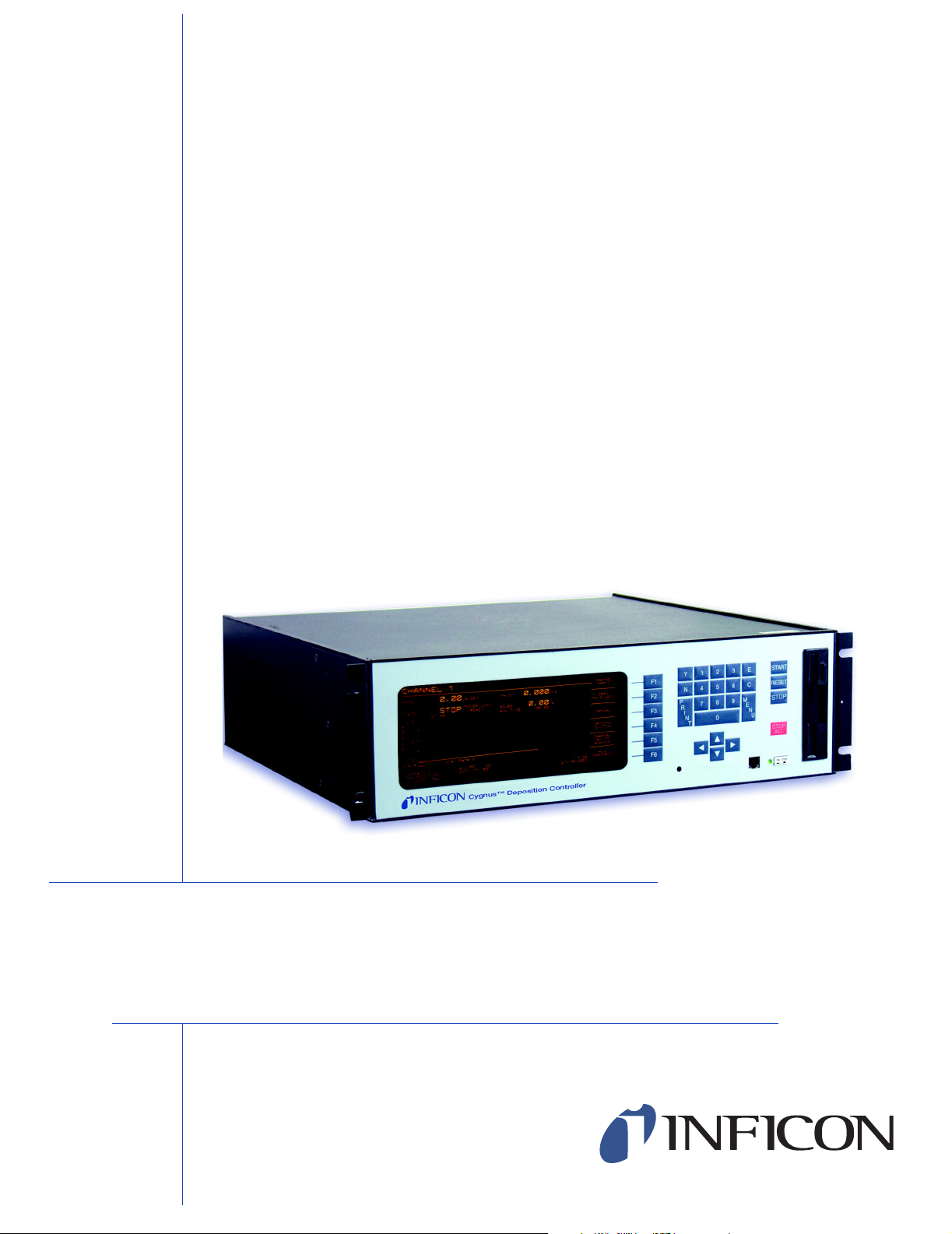
Cygnus is a closed loop process controller designed for use primarily in physical
vapor deposition. The unit monitors and/or controls the rate and thickness of the
deposition of thin films. Deposition rate and thickness are inferred from the
frequency change induced by mass added to a quartz crystal. This technique
positions sensors in the path between or to the side of the source of the vaporized
material and the target substrate. The sensor incorporates an exposed oscillating
quartz crystal whose frequency decreases as material accumulates. The change
in frequency provides information to determine rate and thickness and to
continually control the evaporation power source. With user supplied time,
thickness and power limits and with desired rates and material characteristics, the
unit is capable of automatically controlling the process in a precise and repeatable
manner. User interaction is accomplished via the unit's front panel and consists of
selection or entry of parameters to define the process.
Cygnus Operating Manual
Chapter 1
Introduction and Specifications
The complete system consists of a main electronics unit, the Cygnus, sensor
heads and a crystal interface unit (XIU) for each attached sensor. These items are
generally bundled at the factory and are also sold separately.
The Cygnus Manual provides user information for installing, programming,
calibrating and operating the main electronics unit.
When reading the Cygnus Manual, please pay particular attention to the NOTES,
CAUTIONS, and WARNINGS found throughout the text. The Notes, Cautions, and
Warnings are defined in section 1.2.1 on page 1-2.
You are invited to comment on the usefulness and accuracy of this manual by filling
out the registration card and returning it.
IPN 074-379-P1K
1.1.1 Related Manuals
Sensors are covered in separate manuals.
074-154 - Bakeable
074-155 - CrystalSix
074-156 - Single/Dual
074-157 - Sputtering
074-398 - Crystal12
1 - 1
Page 16
Cygnus Operating Manual
CAUTION
WARNING
WARNING - Risk Of Electric Shock
1.2 Instrument Safety
1.2.1 Definition of Notes, Cautions and Warnings
When using this manual, please pay attention to the NOTES, CAUTIONS and
WARNINGS found throughout. For the purposes of this manual they are defined as
follows:
NOTE: Pertinent information that is useful in achieving maximum instrument
efficiency when followed.
Failure to heed these messages could result in damage
to the instrument.
Failure to heed these messages could result in personal
injury.
Dangerous voltages are present which could result in
personal injury.
IPN 074-379-P1K
1 - 2
Page 17
1.2.2 General Safety Information
WARNING - Risk Of Electric Shock
CAUTION
Do not open the instrument case! There are no
user-serviceable components within the instrument
case.
Dangerous voltages may be present whenever the power
cord or external input/relay connectors are present.
Refer all maintenance to qualified personnel.
This instrument contains delicate circuitry which is
susceptible to transient power line voltages. Disconnect
the line cord whenever making any interface
connections. Refer all maintenance to qualified
personnel.
Cygnus Operating Manual
IPN 074-379-P1K
1 - 3
Page 18
Cygnus Operating Manual
WARNING - Risk Of Electric Shock
1.2.3 Earth Ground
Cygnus is connected to earth ground through a sealed three-core
(three-conductor) power cable, which must be plugged into a socket outlet with a
protective earth terminal. Extension cables must always have three conductors
including a protective earth terminal.
Never interrupt the protective earth circuit.
Any interruption of the protective earth circuit inside or
outside the instrument, or disconnection of the
protective earth terminal is likely to make the instrument
dangerous.
This symbol indicates where the protective earth ground
is connected inside the instrument. Never unscrew or
loosen this connection.
IPN 074-379-P1K
1 - 4
Page 19

1.2.4 Main Power Connection
WARNING - Risk Of Electric Shock
This instrument has line voltage present on the primary
circuits whenever it is plugged into a main power source.
Never remove the covers from the instrument during
normal operation.
There are no operator-serviceable items within this
instrument.
Removal of the top or bottom covers must be done only
by a technically qualified person.
In order to comply with accepted safety standards, this
instrument must be installed into a rack system which
contains a mains switch. This switch must break both
sides of the line when it is open and it must not
disconnect the safety ground.
Cygnus Operating Manual
IPN 074-379-P1K
1 - 5
Page 20

Cygnus Operating Manual
1.3 How To Contact Customer Support
Worldwide support information regarding:
Technical Support, to contact an applications engineer with questions
regarding INFICON products and applications, or
Sales and Customer Service, to contact the INFICON Sales office nearest you,
or
Repair Service, to contact the INFICON Service Center nearest you,
is available at www.inficon.com.
If you are experiencing a problem with your instrument, please have the following
information readily available:
the serial number for your instrument,
a description of your problem,
an explanation of any corrective action that you may have already attempted,
and the exact wording of any error messages that you may have received.
To contact Customer Support, see Support at www.inficon.com.
1.3.1 Returning Your Cygnus to INFICON
Do not return any component of your Cygnus to INFICON without first speaking
with a Customer Support Representative. You must obtain a Return Material
Authorization (RMA) number from the Customer Support Representative.
If you deliver a package to INFICON without an RMA number, your package will be
held and you will be contacted. This will result in delays in servicing your
instrument.
Prior to being given an RMA number, you may be required to complete a
Declaration Of Contamination (DOC) form if your instrument has been exposed to
process materials. DOC forms must be approved by INFICON before an RMA
number is issued. INFICON may require that the instrument be sent to a
designated decontamination facility, not to the factory. Failure to follow these
procedures will delay the repair of your instrument.
IPN 074-379-P1K
1 - 6
Page 21

1.4 Cygnus Specifications
1.4.1 Measurement
Crystal Frequency . . . . . . . . . . . . . . 6.0 MHz (new crystal) to 4.5 MHz
Internal Precision . . . . . . . . . . . . . . . ± 0.004657 Hz over 100 ms sample for
Thickness & Rate Resolution . . . . . . 0.00577 Å (new crystal);
Thickness Accuracy . . . . . . . . . . . . . 0.5% typical, (dependent on process
Frequency Accuracy. . . . . . . . . . . . . ± 2 ppm 0-50 °C
Measurement Frequency . . . . . . . . . 10 Hz
Measurement Technique . . . . . . . . . ModeLock
Cygnus Operating Manual
fundamental and anharmonic frequencies
0.01016 Å (crystal @ 4.5 MHz) over
100 ms sample for material density = 1.0,
Z-ratio = 1.0
conditions, especially sensor location,
material stress, temperature and density)
User Interface. . . . . . . . . . . . . . . . . . CRT and limited membrane keypad. All
parameters accessible through computer
communications. Multiple message areas for
indication of states and detailed indication of
abnormal and stop conditions.
1.4.2 Screens and Parameters
Navigation . . . . . . . . . . . . . . . . . . . . Six soft keys
Structure. . . . . . . . . . . . . . . . . . . . . . Separate screens dedicated to
1) All Channel Data Display, 2) Individual
Channel Data, 3) Channel Parameters,
4) Channel Hardware Parameters,
IPN 074-379-P1K
# of Source / Sensor Channels . . . . 6, Sources can be started or stopped
5) General Parameters, 6) Logic,
7) Maintenance, 8) Communications.
individually or in any combination.
1 - 7
Page 22

Cygnus Operating Manual
1.4.2.1 Instrument Set Up Parameters
Test On. . . . . . . . . . . . . . . . . . . . . . . Yes / No
Time Compressed . . . . . . . . . . . . . . Yes / No
Audio Feedback . . . . . . . . . . . . . . . . Yes / No
RS232 Baud Rate . . . . . . . . . . . . . . 2400, 4800, 9600, 19200
IEEE Address. . . . . . . . . . . . . . . . . . 1-30
Data Logging Path . . . . . . . . . . . . . . 0 = No Data Logging
Data Log XTAL History. . . . . . . . . . . Yes / No
Print Screen Path . . . . . . . . . . . . . . . 2 = Floppy Disk
Print Screen Number . . . . . . . . . . . . 0 to 999
DAC Output Option . . . . . . . . . . . . . 0 = Power/Rate for 6 channels
2 = File, Page Format
3 = File, Comma Format
1 = Power/Thickness for 6 channels
2 = Power/Rate/Thickness for 4 channels
3 = Rate/Thickness for 6 channels
Thickness Equation 1. . . . . . . . . . . . Up to 6 channel numbers can be specified,
Thickness Equation 2. . . . . . . . . . . . Up to 6 channel numbers can be specified,
Thickness Equation 3. . . . . . . . . . . . Up to 6 channel numbers can be specified,
1.4.2.2 Set Up Parameters for Each Source
Source States . . . . . . . . . . . . . . . . . . Film template defines state sequence.
Power Ramps. . . . . . . . . . . . . . . . . . 2 per Source
Power Level . . . . . . . . . . . . . . . . 0.00 to 99.99%
Rise Time . . . . . . . . . . . . . . . . . . 00:00 to 99:59 min:sec
Soak Time . . . . . . . . . . . . . . . . . 00:00 to 99:59 min:sec
each channel number can be used only
once.
each channel number can be used only
once.
each channel number can be used only
once.
IPN 074-379-P1K
Flexible sequencing is a done by skipping
states or vectoring to a different state.
1 - 8
Rate Filter Time . . . . . . . . . . . . . . . . 0.1, 0.4, 1.0, 4.0, 10.0, 20.0, or 30.0 sec
Page 23

Cygnus Operating Manual
Rate & Thickness Control with
Shutter open . . . . . . . . . . . . . . . . . 0.001 to 999.9 Å/sec
Rate Control with Shutter closed . . . 0.001 to 999.9 Å/sec
Idle Ramp . . . . . . . . . . . . . . . . . . . . . 1 per Source
Idle Power. . . . . . . . . . . . . . . . . . 0.00 to 99.99%
Idle Ramp Time . . . . . . . . . . . . . 00:00 to 99:59 min:sec
Deposit After Pre-Deposit. . . . . . . . . Yes / No
Yes = go to Deposit
No = go to Non-Deposit Rate Control
Density . . . . . . . . . . . . . . . . . . . . . . . 0.100 to 99.999 gm/cc
Z-ratio . . . . . . . . . . . . . . . . . . . . . . . . 0.100 to 15.000
Control Loop types . . . . . . . . . . . . . . 0 / 1 / 2
Non-PID, PI, PID
PID Control Mode. . . . . . . . . . . . . . . Fast or Slow Source
Process Gain . . . . . . . . . . . . . . . 0.01 to 999.99 Å/sec/%Power
Primary Time Constant . . . . . . . . 0.010 to 9999.99 seconds
System Dead Time. . . . . . . . . . . 0.010 to 9999.99 seconds
Tooling Factor. . . . . . . . . . . . . . . . . . 1.0 to 999.9%
Secondary Tooling . . . . . . . . . . . . . . 1.0 to 999.9%
Sensors . . . . . . . . . . . . . . . . . . . . . . 2 standard, 4 additional w/optional hardware
Sensor Type . . . . . . . . . . . . . . . . . . . 1 / 2 / 6 / 7 / 12
(Single, CrystalTwo, CrystalSix, Rotary,
Crystal12)
CrystalSix Position Select. . . . . . Indexes to next good crystal
IPN 074-379-P1K
Sensor Switch Output. . . . . . . . . . . . 0 to 38
Sensor Shutter Output . . . . . . . . . . . 0 to 38
Sensor Shutter Output Type. . . . . . . 0 / 1
Normally Open, Normally Closed
Maximum Source Power . . . . . . . . . 0.01 to 99.99%
Minimum Source Power . . . . . . . . . . 0.00 to 99.98%
Maximum Power Option . . . . . . . . . . Stop / Idle Ramp / Continue — can be
selected for each source individually.
Averaging Time . . . . . . . . . . . . . . . . 0 to 30 minutes
Final Thickness . . . . . . . . . . . . . . . . 0.000 to 999.9 kÅ
1 - 9
Page 24

Cygnus Operating Manual
ON Final Thickness . . . . . . . . . . . . . 0 / 1 / 2
0 = Go to Non-Deposit Control
1 = Go to Idle Ramp
2 = Continue
Cross Talk Percent . . . . . . . . . . . . . . 0.00 to 99.99%, Correction for 2 sensors,
multiple instances of 2 sensor correction is
allowed (maximum of 3 instances of 2 sensor
correction).
Crucible Selection . . . . . . . . . . . . . . Turret is indexed to selected position on a
start. Turret feedback is checked whenever a
source is started. Range is from 1 to number
of crucibles.
Number of Crucibles. . . . . . . . . . 1, 4, 8, 16, 32 or 64
Crucible Output . . . . . . . . . . . . . 0 to 37
Crucible Output Type . . . . . . . . . 0 / 1
0 = Normally Open, 1 = Normally Closed.
Turret Feedback. . . . . . . . . . . . . Yes / No
Turret Input. . . . . . . . . . . . . . . . . 0 to 28
Turret Delay . . . . . . . . . . . . . . . . 1 to 60 secs.
RateWatcher® . . . . . . . . . . . . . . . . . Sample and Hold Feature
RateWatcher Option. . . . . . . . . . 0 = None, 1 = Non-deposit,
2 = Non-deposit and Deposit
RateWatcher Time . . . . . . . . . . . 00:01 to 99:59 min:sec
RateWatcher . . . . . . . . . . . . . . . Accuracy 1 to 99%
Source Voltage Range . . . . . . . . . . . 0 to 10 V, 0 to 5 V, 0 to 2.5 V, 0 to -10 V,
0 to -5 V, 0 to -2.5 V
DAC Rate Range . . . . . . . . . . . . . . . 0 = 10 Å/sec, 1 = 50 Å/sec, 2 = 100 Å/sec,
3 = 1000 Å/sec, 4 = 1 Å/sec
DAC Thickness Range. . . . . . . . . . . 0 = 100 Å, 1 = 1000 Å, 2 = 2000 Å,
3 = 3000 Å, 4 = 5000 Å
Substrate Shutter Output . . . . . . . . . 0 to 38
Substrate Shutter Output Type. . . . . 0 / 1
0 = Normally Open, 1 = Normally Closed
IPN 074-379-P1K
1 - 10
Page 25

Crystal Fail Option . . . . . . . . . . . . . . 0 / 1 / 2
Crystal Quality . . . . . . . . . . . . . . . . . 0 to 9
Crystal Stability . . . . . . . . . . . . . . . . . 0 to 9
Auto-Z. . . . . . . . . . . . . . . . . . . . . . . . Yes / No
1.4.3 User Interface
Front Panel / CRT. . . . . . . . . . . . . . . Parameters can be programmed through
Remote Communications . . . . . . . . . Parameters can be programmed through
Cygnus Operating Manual
0 = Time Power,
1 = Idle Ramp
2 = Stop
Can be selected for each source individually.
Cygnus front panel. There is a display for
each source with graphical and text / number
information. There is also a display showing
text and number information for all sources.
computer communications. Complete control
of source state sequencing available by
remote communications.
I/O. . . . . . . . . . . . . . . . . . . . . . . . . . . Control of state sequencing, starting /
stopping each source, is available using
Inputs and Outputs.
PC Applications Software. . . . . . . . . Optional, Compatible with RS232
communications or National Instruments
PCI-GPIB Controller and NI-488.2 protocol.
Operating System. . . . . . . . . . . . Windows 2000
Function . . . . . . . . . . . . . . . . . . . Complete Cygnus programming, Monitoring
of sources.
IPN 074-379-P1K
1 - 11
Page 26

1.4.4 Display
Type / Color / Size . . . . . . . . . . . . . . CRT / Amber /
Format . . . . . . . . . . . . . . . . . . . . . . . 23 kHz Horizontal Scan Rate
Resolution . . . . . . . . . . . . . . . . . . . . 750 W x 350 H Monochrome
Vertical Scan Rate . . . . . . . . . . . . . . 50/60 Hz automatically detected
Thickness Display Range. . . . . . . . . 0.000 to 999.9 kÅ
Thickness Display Resolution . . . . . 1 Å
Rate Display Range . . . . . . . . . . . . . 0.000 to 9999 Å/sec
Rate Display Resolution. . . . . . . . . . 0.001 Å/sec for 0 to 9.999 Å/sec
Power Display Range. . . . . . . . . . . . 0.00 to 99.99%
Cygnus Operating Manual
5" H x 9" W (127 mm x 228.6 mm)
0.01 Å/sec for 10.00 to 99.99 Å/sec
0.1 Å/sec for 100.0 to 999.9 Å/sec
1 Å/sec for 1000 to 9999 Å/sec
Graphic Display Functions . . . . . . . . Rate Deviation at ±10 or ±20 Å/sec or Power
at 0 to 100%
Graphic Scan Rate. . . . . . . . . . . . . . 0 = Auto, 1 = Slow, 2 = Med, 3 = Fast
Display Data Update Rate . . . . . . . . 1 Hz
IPN 074-379-P1K
1 - 12
Page 27

1.4.5 Source / Recorder Outputs
Quantity . . . . . . . . . . . . . . . . . . . . . . 6 standard, an additional 6 are optional with
Type . . . . . . . . . . . . . . . . . . . . . . . . . 6 standard with BNC Connectors for Source
Source control voltage range
(BNC connectors). . . . . . . . . . . . 0 to 10V, 0 to 5V, 0 to 2.5V,
Recorder Voltage Range . . . . . . . . . 0 to 10V
Current rating . . . . . . . . . . . . . . . . . . 20 mA per channel
Resolution . . . . . . . . . . . . . . . . . . . . 15 bits over full range (10 V)
Update Rate . . . . . . . . . . . . . . . . . . . 10 Hz, maximum, (dependent on source
Cygnus Operating Manual
2nd DAC board.
control. 6 optional with 15 pin miniature
D-sub providing analog outputs for Rate and
Thickness.
0 to -10V, 0 to -5V, 0 to -2.5V.
characteristics).
Accuracy. . . . . . . . . . . . . . . . . . . . . . ± 3% full scale
Zero Adjust . . . . . . . . . . . . . . . . . . . . Individual potentiometer
IPN 074-379-P1K
1 - 13
Page 28

Cygnus Operating Manual
1.4.6 Logic Processing
Type . . . . . . . . . . . . . . . . . . . . . . . . . If/Then statements
Logical Functions . . . . . . . . . . . . . . . And; Or; Not; Parentheses
Depth . . . . . . . . . . . . . . . . . . . . . . . . 5 "If" conditions and 5 "Then" results/actions
# of Statements . . . . . . . . . . . . . . . . 100 If/Then
Selectable events. . . . . . . . . . . . . . . Deposition monitor events, states, external
Hierarchy . . . . . . . . . . . . . . . . . . . . . Statements evaluated in numerical order at
Partitioning . . . . . . . . . . . . . . . . . . . . None
Initialization . . . . . . . . . . . . . . . . . . . All outputs transition to their normal states as
per statement
inputs, relays, timers, and counters.
10 Hz any time the unit is on.
early as possible during power-on
initialization sequence.
1.4.7 Relays / Inputs
Relays . . . . . . . . . . . . . . . . . . . . . . . SPST 2.5 A relays rated @ 30 V(dc) or
Relay Ratings. . . . . . . . . . . . . . . . . . 100 VA inductive; 2.5A maximum.
# of TTL Compatible Outputs . . . . . . 14 with optional I/O card. Internally pulled up
Inputs (TTL Compatible). . . . . . . . . . (14 standard, 14 additional optional)
Input Levels
maximum high . . . . . . . . . . . . . . 24 V
minimum high. . . . . . . . . . . . . . . 2.5 V
30 V(ac) RMS or 42 V(peak) maximum;
(8 standard, up to 16 optional with 2
additional I/O cards); D sub connector; relays
are normally open in the power off state, but
may be programmed to normally open or
normally closed during operation.
to 5 V(dc). May be pulled up externally to
24 V(dc) through 2.4k resistor.
minimum high level 0.5mA load @3.75 V
maximum low level 10mA load @1.1 V
IPN 074-379-P1K
1 - 14
maximum low . . . . . . . . . . . . . . . 1.1 V
Scan/Update Rate . . . . . . . . . . . . . . 10 Hz
Page 29

1.4.8 Remote Communications
RS232C Serial Port . . . . . . . . . . . . . Standard
Baud Rates. . . . . . . . . . . . . . . . . . . . 19,200; 9,600; 4,800; 2,400
IEEE488 Parallel Port. . . . . . . . . . . . Optional
IEEE Service Requests . . . . . . . . . . Supported with RQS and MAV status bits
1.4.9 Accessories
Manual Power
Control Connection. . . . . . . . . . . . . . Front panel
Function . . . . . . . . . . . . . . . . . . . . . . Handheld, increase/decrease/stop
Floppy (Optional) . . . . . . . . . . . . . . . 3.5', 1.44 MByte for process and
Connector Kit . . . . . . . . . . . . . . . . . . Connectors for inputs and relays
Operating Manual. . . . . . . . . . . . . . . PDF format on CD
Cygnus Operating Manual
datalog storage
1.4.10 Power
Power . . . . . . . . . . . . . . . . . . . . . . . . 100 +10%, -15% V(ac) 50/60 Hz
120 +10%, -10% V(ac) 50/60 Hz
230 +10%, -10% V(ac) 50/60 Hz
240 +10%, -15% V(ac) 50/60 Hz
Maximum apparent power . . . . . . . . 300 VA
Fuse . . . . . . . . . . . . . . . . . . . . . . . . . 100 V(ac), 120 V(ac) use 4 Amp IEC 127
approved type T
230 V(ac), 240 V(ac) use 2 Amp IEC 127
approved type T
IPN 074-379-P1K
1 - 15
Page 30

Cygnus Operating Manual
1.4.11 Operating Environment
Usage. . . . . . . . . . . . . . . . . . . . . . . . Indoor only
Temperature. . . . . . . . . . . . . . . . . . . 0 to 50 °C (32-122 °F)
Humidity . . . . . . . . . . . . . . . . . . . . . . Up to 85%RH, non-condensing
Altitude . . . . . . . . . . . . . . . . . . . . . . . Up to 2000 meters
Installation (Overvoltage) . . . . . . . . . Category II per IEC 664
Pollution Degree. . . . . . . . . . . . . . . . 1 per IEC 664
1.4.12 Storage Temperature
Storage Temperature . . . . . . . . . . . . -10 to 60 °C (14 to 140 °F)
1.4.13 Warm Up Period
Warm Up Period. . . . . . . . . . . . . . . . None required;
For maximum stability allow 5 minutes.
1.4.14 Size
Not including mounts or user connectors
5.25" H x 17.625" W x 17.3" D
(133.4 mm H x 447.7 mm W x 435.1 mm D)
Including mounts, but no user connectors
5.25" H x 18.85" W x 17.3" D
(133.4 mm H x 478.8 mm W x 435.1 mm D)
1.4.15 Connector Clearance Requirements
Front. . . . . . . . . . . . . . . . . . . . . . . . . Minimum 1.0" (25.4 mm)
Rear . . . . . . . . . . . . . . . . . . . . . . . . . Minimum 4.0" (101.6 mm)
1.4.16 Weight
With all options. . . . . . . . . . . . . . . . . 13.2 kg / 29 lb
1.4.17 Cleaning
IPN 074-379-P1K
1 - 16
Use a mild, nonabrasive cleaner or detergent taking care to prevent cleaner from
entering the unit.
Page 31

1.5 Unpacking and Inspection
1 If the Cygnus control unit has not been removed from its shipping container, do
so now.
2 Carefully examine the unit for damage that may have occurred during shipping.
This is especially important if you notice obvious rough handling on the outside
of the container. Immediately report any damage to the carrier and to INFICON.
3 Do not discard the packing materials until you have taken inventory and have
at least performed a power on verification.
4 Take an inventory of your order by referring to your order invoice and the
information contained in section 1.6 on page 1-17.
5 To perform a power-on verification, see section 1.7 on page 1-20.
6 For additional information or technical assistance, contact your nearest
INFICON Inc. sales office.
1.6 Parts and Options Overview
Cygnus Operating Manual
1.6.1 Base Configurations
Cygnus Control Unit . . . . . . . . . . . . . 779-700-G1 (100 V(ac) 50/60 Hz)
779-700-G2 (120 V(ac) 50/60 Hz)
779-700-G3 (230 V(ac) 50/60 Hz)
779 -700 -G4 (240 V(ac) 50/60 Hz)
Technical Manual . . . . . . . . . . . . . . . 074-379
Hand Controller . . . . . . . . . . . . . . . . 755-262-G1
I/O Relay Ship Kit . . . . . . . . . . . . . . . 760-024-G1
Power Cord . . . . . . . . . . . . . . . . . . . 068-0433
(shielded power cord - North America)
068-0434
IPN 074-379-P1K
Ship Kit . . . . . . . . . . . . . . . . . . . . . . . 779-610-G1 (100 V(ac), 120 V(ac))
(shielded power cord - European)
779-610-G2 (230 V(ac), 240 V(ac))
1 - 17
Page 32

Cygnus Operating Manual
1.6.2 Pre-Installed Options or Spares
Additional Sensor Module (std.) . . . . 760-1132-G1 (up to 2 extra)
Relay Card . . . . . . . . . . . . . . . . . . . . 760-162-G1
Relay Card . . . . . . . . . . . . . . . . . . . . 760-162-G2
I/O Relay Ship Kit. . . . . . . . . . . . . . . 760-024-G1
IEEE488 Parallel . . . . . . . . . . . . . . . 760-142-G1
Communications
Floppy disk . . . . . . . . . . . . . . . . . . . . 760-023-G1
Optional DAC Card . . . . . . . . . . . . . 760-1112-G2
(8 relay outputs, 14 TTL inputs)
(8 relay outputs, 14 TTL outputs)
(8 relay outputs, 14 TTL inputs)
760-024-G2
(8 relay outputs, 14 TTL outputs)
1.6.3 Oscillator Packages, Optional Accessories, and Sensors
IC/5 XIU (Oscillator) . . . . . . . . . . . . . . . . . . . . . . . . . . . . . . . . . . 760-600-G1
Oscillator to vacuum. . . . . . . . . . . . . . . . . . . . . . . . . . . . . . . . . . 755-257-G6
feedthrough cable, 6" (152.4 mm)
IC/5 Unit to Oscillator Cable 15' (4.6 m). . . . . . . . . . . . . . . . . . . 600-1039-G15
IC/5 Unit to Oscillator Cable, 30' (9.2 m) . . . . . . . . . . . . . . . . . . 600-1039-G30
IC/5 Unit to Oscillator Cable, 50' (15.3 m) . . . . . . . . . . . . . . . . . 600-1039-G50
IC/5 Unit to Oscillator Cable, 100' (30.5 m) . . . . . . . . . . . . . . . . 600-1039-6100
Pneumatic Shutter Actuator . . . . . . . . . . . . . . . . . . . . . . . . . . . . 750-420-G1
Control Valve
Sensor Emulator . . . . . . . . . . . . . . . . . . . . . . . . . . . . . . . . . . . . 760-601-G2
Cygnus Editor Applications Software. . . . . . . . . . . . . . . . . . . . . 779-030-G1
IC/5 Oscillator, 15' and 6" cable pkg. . . . . . . . . . . . . . . . . . . . . . 760-025-G15
IC/5 Oscillator, 30' and 6" cable pkg. . . . . . . . . . . . . . . . . . . . . . 760-025-G30
IC/5 Oscillator, 50' and 6" cable pkg. . . . . . . . . . . . . . . . . . . . . . 760-025-G50
IPN 074-379-P1K
1 - 18
IC/5 Oscillator, 100' and 6" cable pkg. . . . . . . . . . . . . . . . . . . . . 760-025-G100
4 Meter Oscillator Kit . . . . . . . . . . . . . . ............................ . . . . . . . 4XI5-nnn
NOTE: For operation with 3 m to 4 m long in-vacuum cable, contact INFICON for
part the number.
Page 33

Cygnus Operating Manual
Standard Sensor. . . . . . . . . . . . . . . . . . . . . . . . . . . . . . . . . . . . . 750-211-G1
Standard Sensor with Shutter. . . . . . . . . . . . . . . . . . . . . . . . . . . 750-211-G2
Compact Sensor. . . . . . . . . . . . . . . . . . . . . . . . . . . . . . . . . . . . . 750-213-G1
Compact Sensor with Shutter. . . . . . . . . . . . . . . . . . . . . . . . . . . 750-213-G2
Sputtering Sensor. . . . . . . . . . . . . . . . . . . . . . . . . . . . . . . . . . . . 750-618-G1
UHV Bakeable Sensor, 12" (304.8 mm) . . . . . . . . . . . . . . . . . . . 007-219
UHV Bakeable Sensor, 20" (508 mm) . . . . . . . . . . . . . . . . . . . . 007-220
UHV Bakeable Sensor, 30" (762 mm) . . . . . . . . . . . . . . . . . . . . 007-221
UHV Bakeable Sensor with Shutter, 12" (304.8 mm) . . . . . . . . . 750-012-G1
UHV Bakeable Sensor with Shutter, 20" (508 mm) . . . . . . . . . . 750-012-G2
UHV Bakeable Sensor with Shutter, 30" (762 mm) . . . . . . . . . . 750-012-G3
Dual Sensor . . . . . . . . . . . . . . . . . . . . . . . . . . . . . . . . . . . . . . . . 750-212-G2
CrystaISix Sensor. . . . . . . . . . . . . . . . . . . . . . . . . . . . . . . . . . . . 750-446-G1
Crystal12 Sensor . . . . . . . . . . . . . . . . . . . . . . . . . . . . . . . . . . . . 750-667-G1
CrystalTwo Switch with two 6" (152.4 mm) BNC cables . . . . . . 779-220-G1
CrystalTwo Switch with two 20" (508 mm) BNC cables . . . . . . . 779-220-G2
NOTE: Contact INFICON for a complete listing of oscillators and sensors.
IPN 074-379-P1K
1 - 19
Page 34

Cygnus Operating Manual
WARNING - Risk Of Electric Shock
WARNING - Risk Of Electric Shock
1.7 Initial Power-On Verification
A preliminary functional check of the instrument can be made before formal
installation. It is not necessary to have sensors, source controls, inputs or relays
connected to do this. For more complete installation information, see Chapter 6,
Installation and Interfaces and Chapter 7, Calibration Procedures.
There are no user-serviceable components within the
instrument case.
Dangerous voltages may be present whenever the power
cord or external input/relay connectors are present.
Refer all maintenance to qualified personnel.
Never interrupt the protective earth circuit.
Any interruption of the protective earth circuit inside or
outside the instrument, or disconnection of the
protective earth terminal is likely to make the instrument
dangerous.
This symbol indicates where the protective earth ground
is connected inside the instrument. Never unscrew or
loosen this connection.
IPN 074-379-P1K
1 - 20
Page 35
Cygnus Operating Manual
1 Confirm that AC line voltage is supplied and proper for the instrument. Line
voltage should be indicated on the instrument back label.
2 Press the power button on the front panel. A green pilot light should be seen
next to the power switch.
3 The fan at the back of the instrument should be exhausting air.
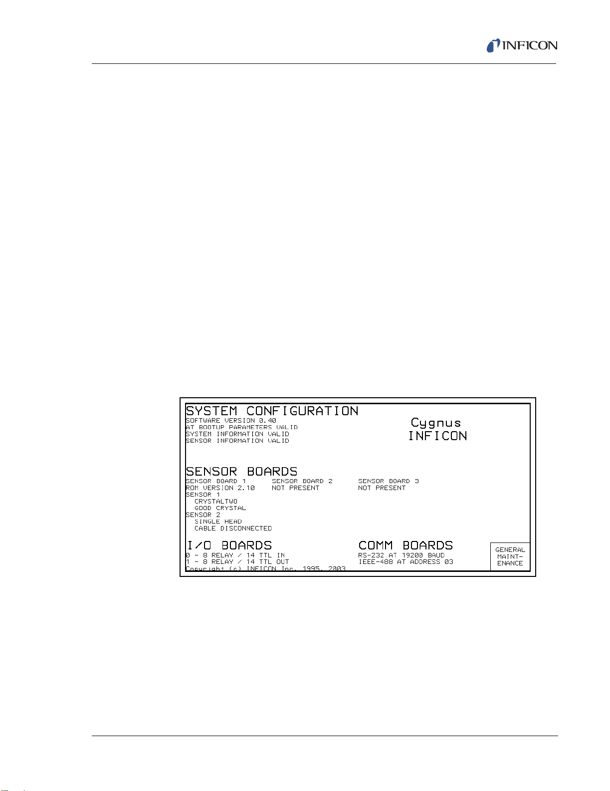
4 Video monitor will display an image similar to the one shown in Figure 1-1.
5 Compare the configuration information on the screen against the unit
configuration ordered.
6 Status of parameter information will be displayed. If information was valid prior
to this power up, it should stay valid.
7 After a delay, the instrument will enter the OPERATE display.
8 In the OPERATE display, confirm that the display is centered vertically. Lines
between the function keys (F1...F6) should align with the lines between the
panels on the right side of the display.
9 Using a non-conducting alignment tool, verify that the brightness pot is
operative. Adjust for the desired brightness. Access to the brightness pot is at
the bottom-center of the face panel, see Figure 2-1 on page 2-1.
Figure 1-1 Cygnus System Status Screen
(Display will vary depending on options present)
IPN 074-379-P1K
1 - 21
Page 36

Cygnus Operating Manual
This page is intentionally blank.
1 - 22
IPN 074-379-P1K
Page 37

2.1 Front Panel Controls
12345
7891011
6
Operational controls for Cygnus are located on the front panel of the instrument, as
depicted in Figure 2-1.
Figure 2-1 Cygnus Front Panel
Cygnus Operating Manual
Chapter 2
Operation
1 CRT Screen
Provides graphical displays, set-up menus, status and error messages.
2 Function Keys
An array of function keys are located adjacent to the screen. These keys are
labeled F1 through F6. They are used to select displays or menu items. Their
IPN 074-379-P1K
function is indicated on the display and is described in subsequent sections.
3 Data Entry Keys
A keypad array with numerics 0 through 9 and keys for Yes (Y), No (N), Enter
(E), Clear (C), Print, and Help used for selection and parameter entry. All
numeric and Yes/No entries need to be followed by Enter. Clear is used to
erase data entry errors. If an illegal value has been entered, Clear will erase the
error message and re-display the last valid data. The Print Screen key is used
to send the display information to the floppy drive. The Help key displays
parameter information and the parameter’s value range on the upper portion of
the display, replacing the screen name area.
2 - 1
Page 38

Cygnus Operating Manual
4 System Switches
An array of four keys that provide START, STOP, RESET and STOP ALL
functions, for process control.
5 3.5" Floppy Disk Access Port
Receptacle for the optional 3.5", 1.44 MB floppy disk.
6 Stop ALL Key
A key which when pressed will place all channels in a STOP state regardless
of the screen display.
7 Power
This switch controls secondary power to the instrument between ON and
STANDBY. Power is provided when the button is in its depressed position. The
instrument is initialized for approximately 5 seconds before providing an
operational screen.
8 Pilot Light
A green pilot light, adjacent to the power switch, is illuminated when power is
on.
9 Remote Control Jack
Receptacle for the wired hand-held remote controller.
10 Cursor Keys
An array of four keys that are used to move the display cursor either up, down,
left or right. The keys auto-repeat; the cursor will continue to move as long as
the key is held down or until a display field boundary is met.
11 Brightness Adjustment
An access hole for the display’s brightness adjustment potentiometer. Use a
nonconductive TV adjustment tool to increase the brightness by turning the
potentiometer clockwise.
IPN 074-379-P1K
2 - 2
Page 39

2.2 Rear Panel Interfaces
1 2345678 9 10
111213
Interfaces for Cygnus are located on the rear panel of the instrument as depicted
in Figure 2-2.
Figure 2-2 Cygnus Rear Panel
Cygnus Operating Manual
1 IEEE488 Connector (Optional)
Provides connections for IEEE-GPIB interface.
2 Digital to Analog Converter (optional)
Provides recorder output for six channels (15 pin miniature D-sub connector).
Outputs are programmable for recorder function.
3 Sensor Connectors - Channels 1 & 2 (standard)
Provides connection for the units two standard sensor channels.
4 Sensor Connectors - Channels 3 & 4 (optional)
Expansion panel to accommodate the optional addition of two more sensors,
IPN 074-379-P1K
sensors 3 & 4.
5 Sensor Connectors - Channels 5 & 6 (optional)
Expansion panel to accommodate the optional addition of two more sensors,
sensors 5 & 6.
6 8 Relay x 14 Input I/O Card (standard)
Provides pin connection for 8 Relays rated for 30 V(dc) or
30 V(ac) RMS or 42 V(peak) maximum, and 14 TTL Inputs.
7 8 Relay x 14 Input I/O Card (optional)
Provides pin connection for 8 relays rated for 30 V(dc) or
30 V(ac) RMS or 42 V(peak) maximum, and 14 TTL inputs.
2 - 3
Page 40

Cygnus Operating Manual
8 8 Relay x 14 Output I/O Card (optional)
Provides pin connection for 8 relays rated for 30 V(dc) or 30 V(ac) RMS or
42 V(peak) maximum, and 14 open collector type outputs.
9 6-Channel DAC (standard)
Provides source control voltage or recorder output for 6 channels (BNC
connectors). Outputs are programmable for Source Control or Recorder
function.
10 24-Volt Supply (standard)
Provides one 24 V(dc) supply rated at 1.75 Amps.
11 Fan Outlet
Exhaust opening for the unit’s miniature fan. A grill is attached for safety.
12 AC Power Inlet
Provides a common connector for various international plug sets. The unit is
factory set for 100 V(ac), 120 V(ac), 230 V(ac) or 240 V(ac) service.
13 RS-232C Remote Communication Connector (standard)
2.3 Displays
Cygnus has many display screens for monitoring and programming processes. At
the top of the hierarchy is the ALL CHANNELS display. The ALL CHANNELS
display allows the user to simultaneously monitor process information for up to six
channels. Three main types of displays, GENERAL PARMS; GENERAL
MAINTENANCE and CHANNEL are accessible from the ALL CHANNELS
DISPLAY: To move from one display to another, use the function keys to the right
of the screen. Figure 2-4 provides an overview of the Cygnus display hierarchy.
Provides a 9-pin RS-232C communications port.
IPN 074-379-P1K
2 - 4
Page 41

2.3.1 ALL CHANNELS Display
1
2
34
8
10
11
5
F1
F2
F6
F3
F4
F5
6
7
9
Figure 2-3 All Channels Display
Cygnus Operating Manual
NOTE: The four channel ALL CHANNELS display is shown when one or two
measurement boards are installed. If three measurement boards are
installed, a six channel ALL CHANNELS display is shown.
ALL CHANNELS Display Description
1 Identifies the channel number associated with the displayed information.
2 Deposition Rate of the channel
3 Accumulated Channel thickness
4 Percent power of individual channel
5 Run time
6 General message area for Test and Lock
7 Power — normal video = level is OK, inverse video = power is at max/min level
IPN 074-379-P1K
and channel is in control.
8 Cumulative thickness for the individual THICK SUM equations defined in the
GENERAL PARAMETER display
9 Rate — normal video = good crystal, inverse video = failed crystal
10 State timer
11 State of individual channel
2 - 5
Page 42

Cygnus Operating Manual
ALL CHANNELS Display Function Keys
F1 GENERAL PARMS
To view the GENERAL PARAMETERS display, press function key F1.
F2 ZERO THICKNESS
To zero the accumulated thickness for the channel indicated by the cursor,
press function key F2.
F3 MANUAL / AUTO
To toggle between the MANUAL and RATE control states for the channel
indicated by the cursor, press function key F3. When in MANUAL, the source
power is controlled by the handheld controller.
F4 CRYSTAL SWITCH
To initiate a crystal switch for the channel indicated by the cursor, press function
key F4.
F5 GENERAL MAINTENANCE
To view the GENERAL MAINTENANCE display, press function key F5.
F6 CHANNEL
To go to the CHANNEL display associated with the current cursor position,
press function key F6.
IPN 074-379-P1K
2 - 6
Page 43

Cygnus Operating Manual
GENERAL
PARMS
GENERAL
MAINTENANCE
CHANNEL
(F1)
(F2) (F6)
LOGIC
DIRECTORY
I/O
MAP
FLOPPY
DISK
COUNTERS/
TIMERS
SELECT LOGIC
STATEMENT
GENERAL
PARAMETERS
EDIT
NAME
SAVE
NAME
CANCEL
NAME
CLEAR
NAME
TOGGLE
TYPE
CHANGE
SELECT NEGATE ADD/DELETE
PARENTHESIS
DELETE
CANCEL
CHANGES
RS232
TEST
SYSTEM
STATUS
CHANGE
TIME/
DATE
CHANNEL ZERO MANUAL/
AUTO
CRYSTAL
CHANNEL
MAINT
PARMS THICKNESS
SWITCH
SWITCH TOGGLE TOGGLE
SENSOR
MANUAL
SENSOR
MAINT
CRUCIBLE SUBSTR
CLEAR
SOURCE
MAINT
QUALITY
STABILITY
ENHANCE
HARDWARE
SHUTTER SHUTTER
ALL CHANNELS
(F1) (F3)(F2)
(F4) (F5) (F6)
(F1) (F2) (F3)
(F1) (F2) (F3) (F4) (F5)
(F1) (F2) (F3) (F4) (F5)
(F1) (F2) (F3) (F4) (F5)
(F5)(F4)(F3)
(F1) (F2) (F3) (F4) (F5)
REPLACE INSERT
(F1) (F2)
ZERO
COUNTER
START
TIMER
CANCEL
TIMER
(F1) (F2) (F3)
TIMER
LOGIC
DIRECTORY
(F6)
PAG E
FORWARD
PAG E
BACK
EDIT
LOGIC
(F1) (F2) (F5)
PROGRAM
LOCK
SENSOR
MAINTENANCE
(F4) (F5)
CRYSTAL ROTATE TEST
XIU
CLEAR
SWITCH XTAL
QUALITY
(F1) (F2) (F3) (F4)
HEAD
STABILITY
GENERAL
MAINTENANCE
(F5)
CRYSTAL
SWITCH
(F1)
ROTATE
XTAL HEAD
(F2)
PARAMETERS
GENERAL
PAR AME TER S
(F6)
CHANNEL
(F6)
CHANNEL
(F6)
ALL
(F6)
CHANNELS
ALL
(F6)
CHANNELS
ALL
(F6)
CHANNELS
LOGIC
(F6)
DIRECTORY
WITH SAVE
SAVE LOAD DELETE
ALL
(F1) (F2) (F3) (F5)
GENERAL
PARAMETERS
(F6)
ALL
(F6)
CHANNELS
TO
FLOPPY
FROM
FILES
FLOPPY
LOGIC
DIRECTORY
(F6)
STATEMENT
(F6)
CHANNEL
(F1) (F6)
CLEAR
FAIL ED
CRYSTALS
Figure 2-4 Cygnus Display Hierarchy
IPN 074-379-P1K
2 - 7
Page 44

Cygnus Operating Manual
2.3.1.1 GENERAL PARAMETERS Display
Figure 2-5 GENERAL PARMATERS Display
See Chapter 4 for a detailed description for programming the General Parameters.
GENERAL PARAMETER Display Function Keys
F1 LOGIC DIRECTORY
For a display that facilitates selection of Logic Statements for editing, press
function key F1.
F2 I/O MAP
To view the I/O MAP display, press function key F2. Provides access to a
display where inputs or outputs may be assigned names and where the output
type may be designated as normally open or normally closed.
F3 FLOPPY DISK
To view the files currently stored on the floppy disk, press function key F3.
Saves or retrieves parameters to or from floppy disk.
F6 ALL CHANNELS
To return to the ALL CHANNELS display, press function key F6.
IPN 074-379-P1K
2 - 8
Page 45

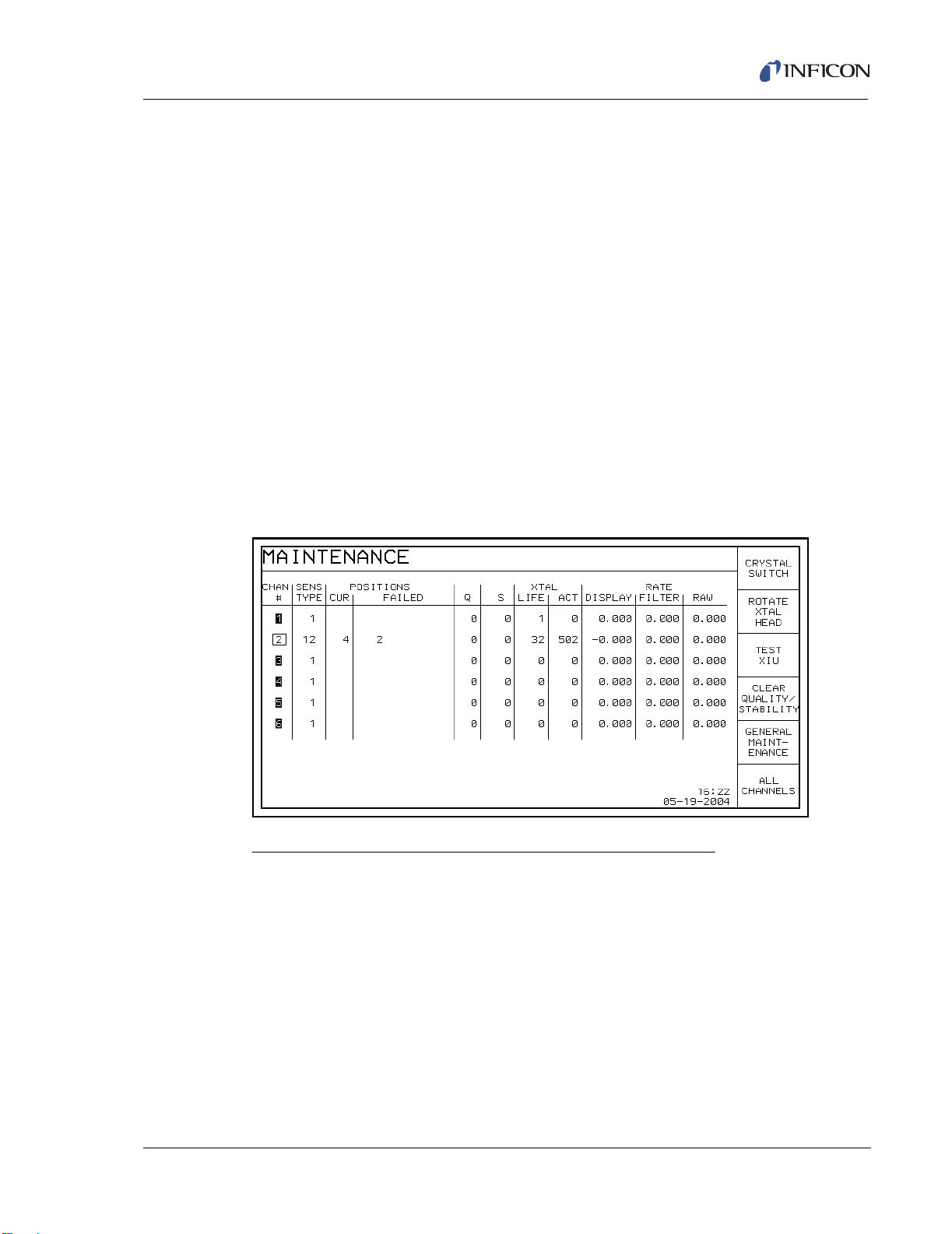
2.3.1.2 General MAINTENANCE Display
These displays provide a simple method for system maintenance and diagnostics.
To access the MAINTENANCE display, press the GENERAL MAINTENANCE
function key (F2) on the ALL CHANNELS display.
Figure 2-6 General MAINTENANCE Display
Cygnus Operating Manual
General MAINTENANCE Display Description
CHAN #
These numbers correspond to the measurement channel numbers on the
Cygnus rear panel. The cursor keys are used to position the box cursor over
the desired channel number. When either the Crystal Switch, Rotate Crystal
Head, Test XIU, or Clear Quality / Stability function key is pressed, the function
will be performed on the channel indicated by the box cursor. It is not allowed
to cursor to channel numbers that do not have the corresponding measurement
card installed. If a crystal fail has occurred for a particular channel this condition
is indicated by displaying the channel number in reverse video.
SENS TYPE
IPN 074-379-P1K
This field indicates the Sensor Type chosen for each channel number. A “1”
indicates a single crystal head, a “2” indicates a CrystalTwo head, a “6”
indicates a CrystalSix sensor head, a “7” indicates a Rotary sensor and a “12”
indicates a Crystal12.
POSITIONS
This field is subdivided into two categories; current position (CUR), and
FAILED. Information is displayed in these fields if the sensor has more than one
position. For a single sensor type, the CUR and FAILED fields have no
meaning. For a multi-position sensor type, the CUR field indicates the current
position of the sensor head. The FAILED field indicates the sensor head
positions containing failed crystals.
2 - 9
Page 46

Cygnus Operating Manual
Q (Crystal Quality value field)
This field displays the value currently accumulated in the Crystal Quality
counter when active. The Crystal Quality counter will become active five
seconds after entering DEPOSIT and if the Crystal Quality parameter is
non-zero. The function of the Crystal Quality counter is described in section
3.2.1 on page 3-2.
S (Crystal Stability value field)
This field displays the value currently accumulated in the Crystal Stability
counter. The function of the Crystal Stability counter is described in section
3.2.1 on page 3-2.
XTAL
This field is subdivided into two categories. The first category, LIFE displays the
crystal life. The second category is a measurement of the crystal activity, ACT.
For a detailed explanation of LIFE and ACT, see section 2.4 on page 2-21.
RATE
This field is subdivided into three categories. These fields are useful in
identifying if a sensor’s rate measurements are becoming erratic. 0.000 will be
displayed in these fields for channels not in use. All values are refreshed at the
display’s one second update rate.
The first category is DISPLAY. The value displayed here is the channel’s
average rate. This average is calculated based on a 1 second average.
The second field labeled FILTER is based on the average of the RAW rate
(100 msec) measurements over the Rate Filter Time selected in the Channel
Parms screen for that particular channel.
The third field is RAW representing the instantaneous 100 msec frequency
change measurement restated in Angstrom/second units.
General MAINTENANCE Display Function Keys
F1 RS232 TEST
To initiate the RS-232C COMM PORT self test, press function key F1. Upon
completion of the test, the unit will display a message indicating the test was
successful and the COMM PORT is okay; or the test failed and the COMM
PORT is bad.
NOTE: The RS-232C Loop Back connector, IPN 760-406-P1 must be installed
on the Cygnus RS-232C port for the self-test to work properly.
F2 SYSTEM STATUS
To access the SYSTEM STATUS display (refer to Figure 1-1 on page 1-21),
press function key F2.
IPN 074-379-P1K
2 - 10
Page 47
F3 CHANGE TIME/DATE
To access the display to edit the time and date for the instrument, press function
key F3.
F4 PROGRAM LOCK
To access a display for setting a program lock code, press function key F4.
F5 SENSOR MAINTENANCE
To access the All Channels Sensor MAINTENANCE display, see Figure 2-7,
press function key F5.
F6 ALL CHANNELS
To return to the ALL CHANNELS display, press function key F6.
2.3.1.2.1 All Channels Sensor MAINTENANCE Display
This display provides a simple way to view sensor information for all the sensors
as well as providing general sensor maintenance functions.
Figure 2-7 All Channels Sensor MAINTENANCE Display
Cygnus Operating Manual
IPN 074-379-P1K
All Channels Sensor Maintenance Display Function Keys
F1 CRYSTAL SWITCH
To initiate a crystal switch for the sensor indicated by the cursor position, press
function key F1.
F2 ROTATE XTAL HEAD
If the sensor number indicated by the cursor position is a CrystalSix, Crystal12,
or Rotary sensor, pressing F2 will sequentially rotate the sensor head through
all positions. This is useful to initialize a CrystalSix, Crystal12, or Rotary sensor
after replacing failed crystals.
2 - 11
Page 48

Cygnus Operating Manual
F3 TEST XIU
To initiate the XIU Self Test, press function key F3. The XIU Self Test
determines whether the Crystal Interface Unit (XIU) and Measurement Card
pair is operating properly.
NOTE: For the XIU Self Test to work properly, the XIU must have the
F4 CLEAR QUALITY / STABILITY
To clear the Quality and Stability counters, press function key F4.
F5 GENERAL MAINTENANCE
To access the General MAINTENANCE display, press function key F5.
F6 ALL CHANNELS
To access the ALL CHANNELS display, press function key F6.
2.3.1.3 CHANNEL Display
6" (152.4 mm) BNC cable (IPN 755-257-G6) attached and must be
disconnected from the sensor feedthrough.
The CHANNEL display (shown in Figure 2-8) provides information about the
specified channel. The rate, thickness, power level, state, state time, and run time
are all updated once a second. Near the bottom of the display is a graph that
provides an analog display of the rate deviation from the desired rate, while the
channel is in a Rate Control state. Alternatively, the graph can display the percent
power being output during a process. The SCALE and SCAN RATE parameters
control the meaning, scaling and speed of the graph.
On the top right of the display is a general message area. This area displays
information that is not channel specific, such as indicating that the instrument is in
TEST mode The region adjacent to the graph displays channel specific status
information,. For a complete list of error and status messages, see Chapter 8.
IPN 074-379-P1K
2 - 12
Page 49

Figure 2-8 CHANNEL Display
1
2
3
45679
10
11
12
14
F1
F2
F3
F4
F5
F6
8
Cygnus Operating Manual
CHANNEL Display Description
1 Identifies the channel number associated with the displayed information.
2 Accumulated Channel thickness
3 General instrument information message area
4 Function key definitions
5 Date and Time
6 Status area
Displays channel specific status information
7 Run time
This timer represents the elapsed time since the last READY state.
IPN 074-379-P1K
8 Crystal life and activity values (see section 2.4 on page 2-21)
9 Scan rate 0 / 1 / 2 / 3
This parameter determines the horizontal axis for the channel graphic display.
Permissible values are 0, 1, 2 and 3. A 0 places the scan rate into the Auto
mode. A 3 sets the scale to three measurements per horizontal pixel, a 2 sets
the scale to 10 measurements per horizontal pixel, while a 1 sets the scale to
40 measurements per horizontal pixel. The default value is zero. When the plot
reaches the right edge it will wrap and erase the plot from the left edge. Auto
mode starts plotting at 3, then compresses and plots at 2, then compresses and
plots at 1’s rate.
2 - 13
Page 50

Cygnus Operating Manual
10 Channel sensor information
This region of the Channel identifies the sensor type currently defined in the
Channel hardware configuration (see section 2.3.1.3.1.1 on page 2-17). If a
value of 2, 6, 7 or 12 is selected for the sensor type, the current crystal position
as well as the quantity of good crystals remaining is displayed.
11 Scale 0 / 1 / 2
Establishes the vertical scale for the channel graphics display. Permissible
values are 0, 1 and 2. A 0 sets the vertical scale to % Power, 1 sets the vertical
scale to ±10 Å/sec, while a 2 sets the vertical scale to ±20 Å/sec. The default
value is 1.
12 Graphical display of rate deviation or power
13 State of channel
14 Rate of the channel
2 - 14
IPN 074-379-P1K
Page 51

Cygnus Operating Manual
CHANNEL Display Function Keys
F1 CHANNEL PARMS
To access the PROCESS (see Figure 2-9) and HARDWARE (see Figure 2-10)
related channel parameters, press function key F1.
F2 ZERO THICKNESS
To resets the channel thickness and zero the channel’s contribution to the
thickness sum equations, press function key F2.
F3 MANUAL
To put the channel in manual control, (so that the power level is controlled by
the hand-held controller), press function key F3. When in manual, the F3 panel
reads AUTO, and pressing it will remove the channel from the manual state and
place it into a rate control state. See State Descriptions (see section 2.6 on
page 2-23) for a more complete description of manual operation.
F4 CRYSTAL SWITCH
To initiate a crystal switch, press function key F4.
F5 CHANNEL MAINTENANCE
To move to the Channel Sensor and Source Maintenance displays, press
function key F5.
F6 ALL CHANNELS
To return to the ALL CHANNELS display, press function key F6.
IPN 074-379-P1K
2 - 15
Page 52

Cygnus Operating Manual
2.3.1.3.1 Channel Parameters Display
The Channel Parameters Display contains CHANNEL specific material and
process related parameters. This display is accessed by selecting the CHANNEL
PARMS function key (F1) from the CHANNEL display. See Chapter 3 for a detailed
description for programming of these parameters.
Figure 2-9 Channel Parameters Display
PROCESS Display Function Keys
F1 HARDWARE PARMS
To access the Channel HARDWARE parameters (see Figure 2-10), press
function key F1.
F6 CHANNEL
To return to the CHANNEL display, press function key F6.
IPN 074-379-P1K
2 - 16
Page 53

2.3.1.3.1.1 HARDWARE PROCESS Display
The Channel HARDWARE display contains channel specific hardware related
parameters. This display is accessed by selecting the HARDWARE PARMS
function key (F1) from the PROCESS display. See section 3.3 on page 3-12 for a
detailed description for programming of these parameters.
Figure 2-10 HARDWARE Display
Cygnus Operating Manual
HARDWARE Display Function Keys
F1 PROCESS PARMS
To access the PROCESS (see Figure 2-9) related channel information, press
function key F1.
F6 CHANNEL
To return to the CHANNEL display, press function key F6.
2.3.1.3.2 Channel SENSOR MAINTENANCE Display
Figure 2-11 SENSOR MAINTENANCE Display
IPN 074-379-P1K
2 - 17
Page 54

Cygnus Operating Manual
SENSOR MAINTENANCE Display Description (refer to Figure 2-11)
Sensor Type
Indicates the Sensor Type as defined on the Channel Hardware display (refer
to Figure 2-10).
XTAL Readings
The values of percent life and activity for the channel sensor crystal
Crystal Status
Depending upon the type of sensor used, this field may be empty (Single), may
identify the current crystal position in addition to the quantity of good crystals
(CrystalTwo); may identify the current crystal position and the position
number(s) of the failed crystal (CrystalSix, Crystal12) or the quantity of good
crystals (Rotary).
Q Count (Crystal Quality value field)
This field displays the value currently accumulated in the Crystal Quality
counter when active. DLY indicates the Crystal Quality counter is not active.
The Crystal Quality counter will become active five seconds after entering
DEPOSIT and if the Crystal Quality parameter value is non-zero.
S Count (Crystal Stability value field)
This field displays the value currently accumulated in the Crystal Stability
counter.
Z-Ratio
Type Material or Auto-Z, value in use.
Frequency
Crystal Fund — normal video = good crystal, inverse video = bad crystal
Anharmonic
Crystal Anharmonic — normal video = good crystal, inverse video = unable to
Auto-Z.
Rate, Power, and Thickness display area
The lower portion of this display shows the Rate, %Power, and Thickness for
the channel.
IPN 074-379-P1K
2 - 18
Page 55

Cygnus Operating Manual
SENSOR MAINTENANCE Display Function Keys
F1 CRYSTAL SWITCH
To initiate a crystal switch, press function key F1.
F2 ROTATE XTAL HEAD
If the channel sensor type is a CrystalSix, Crystal12, or Rotary, press function
key F2 to sequentially rotate the sensor head through all positions. This is
useful to initialize a CrystalSix, Crystal12 or Rotary sensor after replacing failed
crystals, or changing Sensor Type parameter.
F3 CLEAR FAILED CRYSTALS
If the channel sensor type is a CrystalTwo, CrystalSix or Crystal12, press
function key F3 to clear all non current failed crystal position numbers
(CrystalSix, Crystal12) or to increment the number of good crystals
(CrystalTwo), if applicable.
F4 CLEAR QUALITY / STABILITY
To clear the Quality and Stability counters, press function key F4.
F5 SOURCE MAINTENANCE
To access the channel source maintenance display press function key F5.
F6 CHANNEL
To return to the Operate display, press function key F6.
IPN 074-379-P1K
2 - 19
Page 56

Cygnus Operating Manual
2.3.1.3.2.1 Channel SOURCE MAINTENANCE Display
Figure 2-12 Channel SOURCE MAINTENANCE Display
Channel SOURCE MAINTENANCE Display Function Keys
F1 SWITCH CRUCIBLE
To switch the source turret to the crucible position designated by the crucible
parameter, press function key F1. When power is at 0.00% only.
F2 TOGGLE SUBSTRATE SHUTTER
To activate the relay for the substrate shutter, press function key F2. A second
pressing of this key deactivates the substrate shutter relay.
F3 TOGGLE SENSOR SHUTTERS
To activate the sensor shutter relay, press function key F3. Pressing this key a
second time deactivates the sensor shutter relays.
F4 START MANUAL POWER
To enable the hand-held controller to effect power changes to the source output
associated with the channel, press function key F4.
F5 SENSOR MAINTENANCE
To access the channel sensor maintenance display press function key F5.
F6 CHANNEL
To return to the Channel display, press function key F6.
IPN 074-379-P1K
2 - 20
Page 57

Cygnus Operating Manual
2.4 Crystal Life, Starting Frequency and Activity
On the CHANNEL display, crystal life is shown as a percentage of the monitor
crystal’s frequency shift, relative to the 1.50 MHz frequency shift allowed by the
instrument. This quantity is useful as an indicator of when to change the monitor
crystal to safeguard against crystal failures during deposition. It is normal to change
a crystal after a specific amount of crystal life (% change) is consumed. It is not
always possible to use a monitor crystal to 100% of crystal life. Useful crystal life is
highly dependent on the type of material being deposited and the resulting
influence of this material on the quartz monitor crystal. For well-behaved materials,
such as copper, at about 100% crystal life the inherent quality, Q, of the monitor
crystal degrades to a point where it is difficult to maintain a sharp resonance and
therefore the ability to measure the monitor crystal’s frequency deteriorates.
When depositing dielectric or optical materials, the life of a gold, aluminum or silver
quartz monitor crystal is much shorter — as much as 10 to 20%. This is due to
thermal and intrinsic stresses at the quartz-dielectric film interface, which are
usually exacerbated by the poor mechanical strength of the film. For these
materials, the inherent quality of the quartz has very little to do with the monitor
crystal’s failure.
It is normal for a brand new quartz monitor crystal to display a crystal life anywhere
from 0 to 5% due to process variations in producing the crystal. Naturally, this
invites the question, “Is a brand new crystal indicating 5% life spent inferior to a
crystal indicating 1% life spent?”
If a new crystal indicates 5% life spent, it means that either the quartz blank is
slightly thicker than normal (more mechanical robustness), or the gold electrode is
slightly thicker than normal (better thermal and electrical properties), or both. In
either case, its useful life with regard to material deposition should not be adversely
affected. To verify this assertion, laboratory testing was performed on crystals that
covered the crystal life range in question. Results indicate that a brand new crystal
that indicates 3 to 5% life spent is just as good as, if not better than, a crystal
indicating 0 to 2% life spent. As a consequence, it is important to consider the
IPN 074-379-P1K
change in crystal life (%), not just the absolute crystal life (%) indicated.
The activity value is useful for predicting when a crystal needs to be replaced. If a
crystal is about to fail, its series resistance will increase, allowing less current to
flow through the crystal and hence the activity value will decrease. The closer the
activity value is to zero the more imminent a crystal failure.
It also can be used to gauge the health of the sensor head electrical contacts.
Activity values range from a maximum of 650 (healthiest) to a minimum of 0 (least
healthy). For example, if a new monitor crystal is placed into the sensor head and
has a crystal life of near 0%, but the activity value for this crystal is lower than 400,
the sensor head or in-vacuum cable is in need of repair.
2 - 21
Page 58

Cygnus Operating Manual
2.5 Defining a Process
The following procedure is used to define a process. (All steps do not necessarily
have to be followed in the given order.)
1 Make sure the instrument is in READY.
Some configuration and process parameters can be changed only while the
channel is in READY. Therefore, before setting parameters, make sure READY
appears as the state on the CHANNEL display. If it does not, press STOP then
RESET.
2 Configure the sensor.
Configuring the sensor involves designating whether the sensor is a single,
CrystalTwo, CrystalSix, Crystal12 or Rotary sensor, and what output relays are
connected to the sensor shutter and crystal switcher, if any. These parameters
are on the Channel HARDWARE display.
3 Configure the sources.
Configuring the sources involves selecting, the output voltage range and
polarity, and selecting the output relay for the substrate shutter. Also, if a source
has more than one crucible, this is set up in the source configuration. The
source parameters are programmed on the HARDWARE display.
2.5.1 Executing a Process
Once a process has been defined, it is ready to execute.
NOTE: Certain parameters cannot be changed while executing a process. The
Cygnus will not allow these parameters to be changed.
A Process is not being executed when the instrument is in the READY or STOP
state.
STOP freezes a process, the status information on the display is maintained
and the control voltage output is set to zero.
START, pressed once, will continue the process from the point at which it was
stopped.
RESET takes a stopped process back to the beginning of the process.
HINT: It may be desirable to execute a new process in TEST before doing an
actual deposition to check correct shutter operation, sequencing and limits.
IPN 074-379-P1K
2 - 22
Page 59

2.6 State Descriptions
Table 2-1 State Descriptions
STATE CONDITION RELAY CONTACT
Cygnus Operating Manual
STATUS
Substrate
Shutter
Sensor
Shutter
NOTE: The following are Pre-Deposit states.
READY Cygnus will accept a START command
Inactive Inactive
Thickness is not incremented
CRUCIBLE SWITCH Instrument advances to next state when
Inactive Inactive
“turret” input is low, or “turret” delay has
elapsed. If IDLE PWR of the channel using
this source is not equal to zero, power is
set to zero before the crucible position
changes.
RISE TIME 1
SOAK TIME 1
1
1
Source is rising to Soak Power 1 level. Inactive Inactive
Source is being maintained at Soak Power
Inactive Inactive
1 level.
1
Rise Time 1 and Soak Time 1 will be skipped and the channel will start with the
Rise Time 2 state if Idle Power is set to a non-zero value and the channel is currently
at Idle at this non-zero Idle Power.
RISE TIME 2 Source is rising to Soak Power 2 level. Inactive Inactive
SOAK TIME 2 Source is being maintained at Soak Power
Inactive Inactive
2 level.
2
If a channel is linked to another due to crosstalk correction, that channel’s Sensor Shutter will
become active during Soak Time 2 if the linked channel is in Deposit.
2
NOTE: The following are Deposit states.
DEPOSIT Thickness is zeroed on entry. Rate
Active Active
3
control, substrate shutter relay active.
IPN 074-379-P1K
NONDEP CONTROL Rate control, substrate relay contact
Inactive Active
3
inactive. Thickness is not incremented
3
RateWatcher in Delay and Sample will have the sensor shutter active. RateWatcher in Hold will
have the sensor shutter inactive.
NONDEP HOLD Power held constant due to a crystal
Inactive Inactive
failure.
MANUAL Source power controlled by hand-held
Active Active
controller.
TIME-POWER Crystal failed; source maintained at
average control power prior to crystal
Active or
Inactive
Active
failure.
2 - 23
Page 60

Cygnus Operating Manual
Table 2-1 State Descriptions (continued)
STATE CONDITION RELAY CONTACT
STATUS
NOTE: The following are Post-Deposit states.
IDLE RAMP Source changing to Idle Power. Inactive Inactive
STOP Source output set to zero power. The
NOTE: The following is a Non-Deposit state.
MANUAL Source power controlled by hand-held
2.7 Special Features
Cygnus has several special features to enhance the performance of the
instrument.
2.7.1 Crystal Switching
Substrate
Shutter
Inactive Inactive
display is frozen at the last rate and
thickness values.
NOTE: In the STOP state the instrument will accept a START
provided a Crystal Failure for the sensors used in the channel being
started is not present.
Inactive Active
controller.
Sensor
Shutter
Cygnus offers a choice of Single, CrystalTwo, CrystalSix, Crystal12 or Rotary
sensors. The CrystalTwo, CrystalSix, Crystal12, and Rotary sensors provide a
backup monitor crystal in case a crystal fails during deposition. Sensor types are
specified on the Channel Hardware Display.
A crystal switch will automatically occur when:
The instrument is configured for a CrystalTwo sensor type, a channel is
STARTed or running and there is another good crystal available when the
active crystal fails.
The instrument is configured for a CrystalSix or Crystal12, a channel is
STARTed or running, and there is at least one good crystal left in the carousel
when the active crystal fails.
The instrument is configured for a Rotary sensor, the channel is running, and
there is at least one good crystal in the Rotary sensor.
IPN 074-379-P1K
2 - 24
Page 61

A crystal switch will NOT automatically occur:
During a state of STOP or READY.
During deposition, if the secondary crystal of a CrystalTwo sensor fails, or the
last good crystal of a Rotary, CrystalSix, or Crystal12 fails. (In either case a
TIME-POWER, IDLE-RAMP or STOP will occur, depending on the crystal fail
option chosen.)
A crystal switch can be manually executed via the front panel, hand-held controller,
remote communications, or logic statements when the system is configured for
CrystalTwo, CrystalSix, Crystal12 or Rotary sensors.
NOTE: When crystal switching with the hand-held controller, Cygnus must be on
a screen with a channel selected.
2.7.2 Rotary Sensor Crystal Switching
Selecting type 7, Rotary, as the sensor type enables sequential crystal switching
only. Upon a crystal switch the Crystal Switch Output will first close for one second
and then open (i.e., one pulse to move one position). Cygnus will not keep track of
which position the Rotary Sensor is on nor will it keep track of which crystals are
good and which are failed. After the one second pulse, Cygnus measurement
system software will attempt to find the resonant frequency for the crystal in this
position. If the Cygnus does not find a good resonant frequency for this crystal it
will again pulse the Crystal Switch Output for one second and attempt to find a
resonant frequency at this position. There will be a maximum of five attempts to find
a good resonant frequency (i.e., a maximum of five pulses of the Crystal Switch
Output). If a good resonant frequency is not found after five attempts, the Cygnus
will then enter the Time Power, Idle-Ramp or STOP state depending on the Crystal
Fail Option value chosen in the Channel Process Display.
Cygnus Operating Manual
There is to be a maximum of five attempts to find a good resonant frequency.
However, if the Cygnus detects a crystal fail and automatically initiates a crystal
switch it will recognize there has been an automatic crystal switch. The Cygnus will
IPN 074-379-P1K
keep track of the number of times an automatic crystal switch has been done.
Therefore if there have been five automatic crystal switches and then the sixth
crystal fails, Cygnus will go directly to either Time Power, Idle-Ramp, or STOP as
appropriate without any additional pulses.
After a ’Start’ command, all crystals are assumed to be good.
2 - 25
Page 62

Cygnus Operating Manual
2.7.3 Source/Crucible Selection
Cygnus can control a source with up to 64 crucibles, through up to six binary
encoded relays. This is configured by setting the Number Of Crucibles, Crucible
Outputs, Turret Feedback, Turret Input, and Turret Delay parameters on the
Channel Hardware display.
To define which crucible to use for the channel, set the “crucible” parameter on the
CHANNEL PROCESS display. If the current crucible position is different from the
one requested upon STARTing, the system’s turret controller would move into
position. This will be signified on the Channel display by the state indicator
CRUCIBLE SWITCH. Sequencing will continue on to RISE 1 after either the turret
delay time expires or an input indicates the turret is in position, depending on which
option is chosen. The specific method used is determined by the parameter Turret
Feedback on the Channel Hardware display.
NOTE: If the source has been idling at a nonzero power when the START is
initiated, the power will be dropped to zero before the crucible is changed.
2.7.3.1 Example: Programming Turret Source Crucible Selection
Interfacing a turret source controller to the Cygnus requires both hardware
connections to the turret controller and properly defining certain instrument
parameters.
Proceed to the Channel Hardware display for the source that is going to be defined
as the turret source.
1 Designate the Number of Crucibles; for example, 4.
2 Select the Crucible Output. This defines the number of the first relay that
encodes the crucible number selected by the active channel. Relays are
defined sequentially with the first relay containing the least significant bit (LSB).
The greater the number of crucibles selected, the greater the number of relays
required. The number required is based on binary encoding (actual coding is
binary -1, with 00 representing position 1 and 11 representing position 4). Any
unused sequence of relays may be used if it is long enough to provide sufficient
selections.
3 Select the Crucible Output Type as normally open (NO), or normally closed
(NC).
Example:
Number of crucibles = 4
Crucible output = 6
Crucible output type = NO
IPN 074-379-P1K
2 - 26
For this example, wiring to the controller is based on Table 2-2. Only relays 6
and 7 are needed to encode the four possible positions
Page 63

Cygnus Operating Manual
.
Table 2-2 Wiring To The Controller
Crucible
Position Contact Status
Relay #6 Relay #7
1 Open Open
2 Closed Open
3OpenClosed
4 Closed Closed
NOTE: If the crucible output type were normally closed (NC), Table 2-2 would
need to be modified by exchanging open and closed.
4 Determine whether Turret Feedback is desired. This allows the turret position
controller to stop further instrument processing until the requested turret
position is satisfied. If chosen, a turret input must be connected to the turret
position controller’s feedback signal within one minute, else a STOP Crucible
ERR occurs.
If Turret Feedback is not chosen, program a Turret Delay Time, which allows
an adequate time for positioning to take place. Once the delay time has
expired, instrument state processing continues.
5 The selection of a particular crucible for a channel is defined in the CHANNEL
PROCESS display.
IPN 074-379-P1K
2 - 27
Page 64

Cygnus Operating Manual
2.7.4 Hand-Held Controller
A Hand-Held Controller, see Figure 2-13, is provided as an accessory with the
Cygnus. The Controller serves as a wired remote to manually control power, switch
crystals and produce a STOP.
The Controller is attached to the instrument with a modular plug to the front panel.
Power is affected (only when in Manual mode) by moving the POWER/STOP
switch laterally. A STOP is produced by moving the POWER/STOP switch down
(only when in Manual mode). An All STOP is performed when the STOP function
is pressed twice within one second, or is continuously pressed. When in a READY
or STOP state and the instrument is on the SENSOR Maintenance display, a
crystal switch is activated by pressing the red button on the body of the controller.
The ship kit includes a convenience hook for the Controller that can be attached to
the instrument’s mounting ears or some other accessible location.
Figure 2-13 Hand-Held Controller
2 - 28
IPN 074-379-P1K
Page 65

2.7.5 Test Mode
CAUTION
Rate Display
40
Density (gm/cc)
--------------------------------------
x
Tooling %
100
-------------------------
Å/sec=
This instrument contains a software-controlled test mode which simulates actual
operation. Optionally, time can be compressed so that a long process can be
simulated in one tenth of the time. The purpose of the test mode is to verify basic
operation and to demonstrate typical operation. The rate display during test mode
operation is:
Crystal fails are ignored in test mode. Crystal switching is disabled. All other relays
and inputs operate normally.
2.7.6 Floppy Disk (Optional)
The floppy disk drive is an optional accessory for the Cygnus. This option allows
storage of all parameter information to the 3.5 inch 1.44 MByte floppy diskette. The
maximum number of files that may be stored onto the floppy disk is 224 for a 1.44
MByte diskette and 112 files when using a 720 KByte diskette
Cygnus Operating Manual
[1]
The parameter set may be stored under a new or existing filename and retrieved
from an existing file. A file containing the Cygnus parameter set is referred to as a
configuration file.
Multiple files may be contained on one diskette. Filenames may be eight characters
long. All files must be contained on the root directory. Storage/retrieval from
sub-directories is not allowed.
The instrument supports the writing of filenames using alphanumeric characters
selected using the cursor keys. Characters A through Z and numbers 0 through 9
inclusive are available. The instrument has the ability to display the files contained
on the diskette. A scrolling feature is enabled to view those filenames that cannot
fit on the screen. Error messages include: Disk Full; File Not Found; Disk Write
Protected; Media Error; Disk not Found; File is Read Only.
IPN 074-379-P1K
Do not bend the diskette.
Keep the diskette dry and do not expose the diskette to
temperature extremes.
Do not remove the diskette from the instrument while a
save or retrieve operation is taking place.
2 - 29
Page 66

Cygnus Operating Manual
2.7.7 Lock Codes
A Program Lock Code can be entered to prevent unauthorized changing of
parameters. This Lock Code can be entered through the front panel using the
PROGRAM LOCK display. An additional Lock Code can be entered through
remote communications to prevent parameter entry from the front panel while
communicating to Cygnus using remote communications. The word “LOCK” in
inverse video will be displayed in the upper right corner of the display.
HINT: To clear the lock, hold down the clear key on power up. HOWEVER, if no
2.7.8 Datalog
Datalog automatically saves to diskette every time a source shutter closure occurs.
When the Datalog data is saved to a diskette, the information will be saved under
a filename.
Datalog files saved to diskette will be automatically named using the date and
Channel number. The format of the filename is YYMMDDC#.IDL where YY is 00 to
89 for the last two digits of the year 20YY, MM is 01 to 12 for the month, DD is 1 to
31 for the day and # is the Channel number 1 to 6. If the diskette already contains
a file with the same filename as the new datalog information, the new datalog
information will be appended to the old file.
lock code is present, all parameters will be cleared by doing this.
At each source shutter close, the datalog information will be appended to the file
(when saved to diskette) until the end of the Process.
The Datalog data set is defined as follows:
IPN 074-379-P1K
2 - 30
Page 67

Cygnus Operating Manual
DATE: MM-DD-YYYY
TIME: XX:XX
CHANNEL #: #
RUN TIME: XX:XX
DEPOSITION TIME: XX:XX
THICKNESS: ###.### kÅ
AVE. AGG. RATE: ###.### Å/s
AVE. RATE DEV: ##.### Å/s
ENDING POWER: ##.## %
AVE. POWER: ##.## %
COMPLETION: POST-DEPOSIT NORMAL
(time-power, ave. value,
crystal fail, remote, keyboard,
max. power, hand-held controller)
Crystal Use History (example)
SENSOR 1
BEG. END BEG. END BEG. END
XTAL FREQ. FREQ. LIFE LIFE ACT. ACT. STAB. QUAL.
1 5975323 5876991 0% 2% 245 240 30 22
2 5978368 5879012 0% 2% 225 189 1200 99
3 5768733 5677987 3% 5% 176 168 0 0
4 5346278 5129870 48% 51% 150 105 0 0
5 4876789 4567899 78% 81% 101 101 25 1
6 4678843 4500000 98% 100% 100 92 0 0
SENSOR 2
BEG. END BEG. END BEG. END
XTAL FREQ. FREQ. LIFE LIFE ACT. ACT. STAB. QUAL.
2 5978368 5879012 0% 2% 225 189 1200 99
3 5768733 5677987 3% 5% 176 168 0 0
5 4876789 4567899 78% 81% 101 101 25 1
SENSOR 8
BEG. END BEG. END BEG. END
XTAL FREQ. FREQ. LIFE LIFE ACT. ACT. STAB. QUAL.
1 5975323 5876991 0% 2% 245 240 30 22
IPN 074-379-P1K
2 - 31
Page 68

Cygnus Operating Manual
If two Channels are co-deposited, the first Channel to have a source shutter close
will be data-logged first.
The ability to turn ON/OFF datalogging and where to output the datalog data set is
determined by a programmable parameter located in the General Parameters
display. The CRYSTAL USE HISTORY data is an optional subset of the datalog
string. A second parameter located in the General Parameters display is used to
determine if the CRYSTAL USE HISTORY is to be output. Additionally, the datalog
string format is selectable between a page format and a comma delimited format.
The comma delimited format is actually comma-and-quote delimited intended for
file importation into a spreadsheet program. When a spreadsheet program imports
a file having the comma delimited format data groups that are strictly numbers
become value entries, data groups surrounded by quotes are stored as labels. For
the page format, only those sensors which are used in a particular Material for a
particular Layer will be datalogged. For the comma delimited format, all the data
fields are returned for all the sensors and crystals. If a sensor is not used during
the deposition, the data field will contain a zero.
Outputting the Datalog Data Set to multiple outputs at the same time (for example,
Save to diskette and Output to Remote Comm at the same time) is not allowed.
2.7.9 Auto Soak 2
When Auto Soak 2 is enabled, the Soak 2 power parameter will automatically be
updated at the end of deposit or nondeposit control. The value will be the power at
the end of control. This allows the next Soak 2 on the channel to be done at the last
power used to maintain control.
To enable Auto Soak 2, the parameter Dep After PreDep is set to 2.
NOTE: The Soak 2 power parameter retains the new value even if Auto Soak 2 is
subsequently disabled.
IPN 074-379-P1K
2 - 32
Page 69

3.1 Introduction
ALL CHANNELS DATA DISPLAY
CHANNEL (Channel Graphical Display)
CHANNEL PARAMETERS
HARDWARE PARAMETERS
Cygnus can store the definition parameters for 6 Channels (or sources). There are
three primary displays associated with each Channel. These are the Channel
Parameters display, the Channel Hardware parameters display, and a graphical
data display. Each Channel is completely defined by programming Channel
Parameters and Channel Hardware parameters. Channel Parameters define the
material to be deposited and the deposition profile, for example: Density, Z-Ratio,
Rise Times and Soak Times. Channel Hardware parameters define the
digital-to-analog (DAC) functions, sensor type, as well as the shutter and crucible
outputs.
Figure 3-1 Display Tree for Channel Set Up
Cygnus Operating Manual
Chapter 3
Channel Parameters
Channel set up is initiated by selecting the Channel (F6) key in the All Channels
data display. Selecting F6 brings up the Channel Graphical Display for the Channel
number indicated by the cursor.
IPN 074-379-P1K
3 - 1
Page 70

Cygnus Operating Manual
3.2 Channel Parameters
Channel definition is done by pressing the F1 function key on the CHANNEL
display. Selecting F1 brings up the Channel Parameters display as shown
in Figure 3-2.
Figure 3-2 Channel Parameters Display
Channel Parameters Display Function Keys
F1 HARDWARE PARMS
To access the Channel Hardware Parameters Display, select function key F1
F6 CHANNEL
To return to the Channel Graphical display, select function key F6.
3.2.1 Channel Parameter Definitions
DENSITY . . . . . . . . . . . . . . . . . . . . . 0.100 to 99.99 gm/cc (default = 1.000)
This parameter is specific to the material being deposited onto the Crystal. It is
one of two parameters that relate the mass loading on the crystal to a thickness.
Z-Ratio. . . . . . . . . . . . . . . . . . . . . . . 0.100 to 15.000 (default = 1.000)
This parameter is specific to the material being deposited. It is one of two
parameters that relate the mass loading on the crystal to a thickness. This
parameter is superseded if Auto Z-Ratio is selected.
TOOLING . . . . . . . . . . . . . . . . . . . . . 1.0 to 999.9% (default = 100.0)
This is a correction factor used for correlating the thickness accumulation on
the crystal with the thickness accumulation on the substrate. This thickness
difference is due to the geometric distribution of material flux from the source.
IPN 074-379-P1K
3 - 2
Page 71

Cygnus Operating Manual
TOOLING TFiTmTx=
The tooling factor is calculated using the equation:
[1]
where TF
T
= Thickness on the Crystal.
x
= Initial Tooling Factor, Tm = Actual Thickness at the Substrate, and
i
If the TOOLING parameter is changed, the new TOOLING value is used for
subsequent calculation of the rate and thickness. Also, the thickness
accumulated thus far will be re-scaled based on the change to the TOOLING.
SECONDARY TOOLING . . . . . . . . . 1.0 to 999.9% (default = 100.0)
This is a second tooling factor for use with the CrystalTwo Switch. It allows a
second tooling factor for the second crystal of the CrystalTwo Switch to
accommodate the thickness difference between the two different crystal
positions. The function is the same as the Tooling factor and is calculated in the
same manner.
CONTROL LOOP . . . . . . . . . . . . . . 0, 1, 2 (default = 2)
This parameter establishes the control loop algorithms pertaining to either a
slow responding source or a fast responding source. Permissible values are 0,
1, or 2. Select a 0 to choose the non-PID control loop, good for fast- and
medium-speed responding systems with high noise levels (e.g., an electron
beam gun with or without a liner, having a large sweep amplitude of low
frequency, 10 Hz or less). Select a 1 for the PI control loop, good for fast,
medium, or slow systems with medium noise levels (e.g., an electron beam gun
with medium sweep amplitude frequency, 20 to 100 Hz; also, sputtering and
resistive sources). Select a 2 for the PID Control Loop, good for medium or slow
systems with low noise levels (e.g., an electron beam gun with sweep off or at
a high frequency, 100+ Hz; also, sputtering and resistive sources).
IPN 074-379-P1K
PROCESS GAIN . . . . . . . . . . . . . . . 0.01 to 999.99 Å/sec/% pwr (default = 10.00)
This parameter determines the change in % Power for a given rate deviation
(dRate/dPower). The larger the process gain value, the smaller the change in
power for a given rate error.
PRIMARY TIME CONSTANT. . . . . . 0.010 to 9999.99 sec (default = 1.00)
This is the evaporation source’s time constant. This value is defined as the time
difference between the actual start of a change in rate and the time at which
63% of the rate step is achieved. This value may be measured according to the
above criterion or it may be determined empirically. This parameter is disabled
if the CONTROL LOOP option parameter is set to 0.
SYSTEM DEAD TIME . . . . . . . . . . . 0.010 to 9999.99 sec (default = 1.00)
This value is defined as the time difference between a change in % power and
the start of an actual change in rate. This parameter is disabled if the
CONTROL LOOP option parameter is set to 0.
3 - 3
Page 72

Cygnus Operating Manual
MAXIMUM POWER . . . . . . . . . . . . . 0.0 to 99.99% (default = 90.00)
This parameter is used to set the maximum permissible % power level. The
control voltage output will not exceed this limit.
MINIMUM POWER . . . . . . . . . . . . . 0.0 to 99.98% (default = 0.00)
This parameter is used to set the minimum permissible % power level. The
control voltage output will not go below this limit during either the Deposit or
Non-Deposit Rate control states.
Power Ramps (Pre deposit states)
The next six parameters — Soak Power 1, Rise Time 1, Soak Time 1, and Soak
Power 2, Rise Time 2 and Soak Time 2 — are used to define two power ramps
provided to precondition materials.
SOAK POWER 1 . . . . . . . . . . . . . . . 0.0 to 99.99% (default = 0.00)
This parameter is usually set to the power level at which the source material
just begins to melt. The instrument ramps the power level from zero to Soak
Power 1 linearly over the time period Rise Time 1.
RISE TIME 1 . . . . . . . . . . . . . . . . . . 00:00 to 99:59 min:sec (default = 00:00)
This parameter provides the time period over which the source power is
ramped from 0 to Soak Power 1. See note.
SOAK TIME 1 . . . . . . . . . . . . . . . . . 00:00 to 99:59 min:sec (default = 00:00)
This parameter provides the time period for which the instrument holds at Soak
Power 1. See note.
NOTE: Rise Time 1 and Soak Time 1 will be skipped and the channel will start with
the Rise Time 2 state if Idle Power is set to a non-zero value and the
channel is currently at Idle at this non-zero Idle Power.
SOAK POWER 2 . . . . . . . . . . . . . . . 0.00 to 99.99% (default = 0.00)
This parameter sets the power level at which the rate from the source very
nearly matches the desired deposition Rate. If Auto Soak 2 is enabled, this
parameter will automatically be updated when leaving deposit or nondeposit
control.
RISE TIME 2 . . . . . . . . . . . . . . . . . . 00:00 to 99:59 min:sec (default = 00:00)
This parameter sets the time period in which the instrument linearly ramps the
power level from Soak Power 1 to Soak Power 2.
IPN 074-379-P1K
3 - 4
SOAK TIME 2 . . . . . . . . . . . . . . . . . 00:00 to 99:59 min:sec (default = 00:00)
This parameter sets the time period for which the instrument holds the power
level at Soak Power 2.
Page 73

Cygnus Operating Manual
DEP AFTER PREDEP . . . . . . . . . . . 0, 1, 2 (default = 1)
This parameter is used to determine which rate control state to enter after Soak
Time 2. It will also determine whether Auto Soak 2 is enabled.
0 = NonDeposit Control after Soak 2. No Auto Soak 2.
1 = Enter Deposit Control after Soak 2. No Auto Soak 2.
2 = Enter Deposit Control after Soak 2. Enable Auto Soak 2.
RATE . . . . . . . . . . . . . . . . . . . . . . . . 0.000 to 999.9 Å/sec (default = 0.000)
NOTE: Rate = 0.000 will take a channel in control to post deposit.
This specifies the rate at which the deposition is to be controlled during the
DEPOSIT and NON-DEPOSIT CONTROL states. The Rate is calculated
based on:
The rate information acquired by the sensor in use, based on the density
and tooling values entered for this Channel.
The tooling factor that corrects for any relative difference in flux distribution
reaching the sensor.
FINAL THICKNESS . . . . . . . . . . . . . 0.000 to 999.9 kÅ (default = 0.000)
This is the thickness setting that triggers the end of the DEPOSIT state. The
Substrate Shutter output returns to its normal state. The deposition profile then
proceeds to the State indicated by the ON FINAL THICK parameter value, or
by a user supplied input via the I/O or one of the Remote Communications
ports.
ON FINAL THICKNESS. . . . . . . . . . 0, 1, 2 (default = 1)
The On Final Thickness parameter value determines the next step of the
deposition profile.
0 = NonDeposit Control. Entering a value of 0 directs the deposition profile to
enter the NonDeposit Control state, returning the substrate shutter output to its
IPN 074-379-P1K
normal state, when the final thickness value is reached during the Deposit
state.
1 = Idle Ramp. Entering a value of 1 directs the deposition profile to enter the
Idle Ramp state when the final thickness value is reached during the Deposit
state.
2 = Continue. Entering a value of 2 directs the deposition profile to continue in
the Deposit state. Thickness continues to be accumulated.
3 - 5
Page 74

Cygnus Operating Manual
AVERAGING TIME . . . . . . . . . . . . . 0 to 30 min (default = 0)
This parameter value determines the amount of time used in calculating the
average rate and average power for use in Time Power.
The Averaging Time parameter is the time interval used to calculate both the
average rate and average power applied, if a crystal fails, for Time-Power and
Non-Deposit Hold states. When the Averaging TIme parameter value is 0, then
a 2.5 second average, ignoring the most recent 0.5 second, is the averaging
interval.
A channel warning ABBREVIATED AVERAGE is generated if the averaging
interval has not been reached, but there was at least a "complete whole minute"
of data to average.
A channel error NO TIME POWER AVG is generated if a crystal fail occurred
within the first minute of control with Averaging TIme set >0. This error also
occurs if there is a crystal fail during the first 2.5 seconds of control with the
Averaging TIme =0. (There are also SC and RC commands to get and set the
average rate and average power values.)
Idle Ramp State
The next two parameters define an idle ramp provided to maintain the control
voltage power level after the Deposit or NonDeposit Control state. Control voltage
is ramped from the power level at the end of the Deposit (or NonDeposit Control)
state to the Idle Power level. The control voltage is maintained at the Idle Power
level until the instrument enters the STOP state or until the Channel is started
again. If the Idle Power is non-zero, the started channel will skip Rise 1 and
Soak 1, and will begin at Rise 2.
IDLE POWER . . . . . . . . . . . . . . . . . 0.0 to 99.99% (default = 0.00%)
This is one of two parameters used to affect an Idle Power Ramp. This value is
the power level at which the source is maintained after the DEPOSIT (or
NonDeposit Control) state. Idle Power is usually the same as Soak Power 1.
IDLE RAMP TIME . . . . . . . . . . . . . . 00:00 to 99:59 min:sec (default = 00:00)
This is the time interval over which the source power is ramped linearly from
the power level at the end of Deposit (or NonDeposit Control) to Idle Power.
IPN 074-379-P1K
3 - 6
Page 75

Cygnus Operating Manual
CRUCIBLE. . . . . . . . . . . . . . . . . . . . 1 to the maximum number of crucibles
programmed. (default = 1)
This parameter identifies which crucible of a multiple pocket source to use
when the channel is started.
CRYSTAL QUALITY . . . . . . . . . . . . 0 to 9 (default = 0)
This parameter is used to ensure tight rate control by monitoring the information
obtained from the crystal. It can be used to effect a crystal fail when operating
in the single frequency mode. The “single frequency” mode is when the Z-Ratio
type is set for Material Z, “dual frequency” mode is when the Z-Ratio type is set
for Auto Z. See Table 3-1.
Table 3-1 Crystal Quality Number and Threshold of Rate Deviation
Crystal Quality
Number
92.5%
85.0%
77.5%
6 10.0%
5 12.5%
4 15.0%
3 20.0%
2 25.0%
1 30.0%
0 Disabled
Threshold of
Rate Deviation
For each rate reading, the percent relative deviation from the sensor’s rolling
average rate is calculated. Each time this deviation is greater than the allowed
IPN 074-379-P1K
percent relative deviation, as determined by the Crystal Quality value, a counter
is incremented by one count. If the deviation is within tolerance, the counter will
count down. (The counter will not count below zero.) When the count reaches
100, a crystal fail will be initiated. In this manner only sustained erratic rate
readings will trigger a crystal fail and instantaneous noise will be ignored.
If Auto Z is in use, the crystal quality will trigger an Auto Z failure instead of a
crystal fail. This will change the instrument from dual frequency measurement
mode to single frequency measurement mode. For some materials, it is
possible to regain rate stability by this change. Once the switch to single
frequency has occurred and a waiting period has elapsed (four times the
Primary Time Constant plus the System Dead Time plus ten seconds), the
counter will again track the rate deviation. If the counter reaches 100 a second
time, a crystal fail will be triggered.
3 - 7
Page 76

Cygnus Operating Manual
CRYSTAL STABILITY . . . . . . . . . . . 0 to 9 (default = 0)
The Crystal Stability parameter can also be used to effect a crystal fail. In
normal operation, when mass is added to a crystal its frequency of oscillation
will decrease. There are, however, a number of reasons, such as thermal
shock, high stresses in the film, electrical arcing from an electron beam gun, or
frequency instabilities, that may cause a positive frequency shift between
successive measurements. The Crystal Stability function is used to monitor
these positive frequency excursions while the Channel is active. Values range
from 0 to 9. The default value of 0 disables the function. Values 1 through 9
correspond to the maximum positive frequency accumulation permitted. See
Table 3-2.
Table 3-2 Crystal Stability Number and Positive Frequency Accumulation
Crystal Stability
Number
925
8 100 (max single shift of 50)
7 100
6 200 (max single shift of 100)
5 200
4 400
3 500
21000
1 5000 (max single shift of 1250)
0 Disabled
Positive Frequency
Accumulation (Hz)
Each time there is a positive shift in frequency, the magnitude of the positive
frequency excursion is accumulated. If the cumulative total, or the maximum
single shift, exceeds the limit set by the Crystal Stability value a crystal fail
function is triggered.
IPN 074-379-P1K
3 - 8
CRYSTAL FAIL OPTION . . . . . . . . . 0, 1, 2 (default = 1)
This parameter value determines what action will be taken if there is a crystal
failure for this Channel during control.
0 = Time Power. Entering a value of 0 will cause the Channel to enter the Time
Power state upon a crystal failure.
1 = Idle Ramp. A value of 1 will cause the Channel to enter the Idle Ramp state
upon a crystal failure.
2 = Stop. A value of 2 will cause the Channel to Stop upon a crystal failure.
Page 77

Cygnus Operating Manual
MAX POWER OPTION . . . . . . . . . . 0, 1, 2 (default = 1)
This parameter value determines what action will be taken if the Channel
reaches maximum power and is held at maximum power for 5 seconds.
0 = Continue. Selecting a value of 0 will allow the Channel to continue in its
current state.
1 = Idle Ramp. A value of 1 will cause the Channel to enter the Idle Ramp state.
2 = Stop. A value of 2 will cause the Channel to Stop.
RateWatcher™ Sample and Hold Feature
Four parameters — RateWatcher Option, RateWatcher Averaging Time,
RateWatch Time and RateWatch Accuracy — enable the Sample and Hold feature.
When enabled, this feature periodically samples the deposition rate by
automatically opening the sensor shutter and exposing the sensor to the deposition
source. The power is adjusted so the actual rate is set to the desired rate. The
sensor shutter is then automatically closed and power is held constant at the
adjusted level. A five second time delay for thermal stabilization occurs between
opening the shutter and taking measurements.
The RateWatcher Sample phase uses the measured deposition rate to control the
source power. When the deposition rate meets the requirements of the
RateWatcher Accuracy parameter, the RateWatcher Acceptance Window Time is
started. If the rate falls out of the RateWatcher Accuracy requirement, the
RateWatcher Acceptance Time Interval is reset to zero.
If the deposition rate meets the RateWatcher Accuracy requirement for the duration
of the Acceptance Window Time, the sensor shutter is closed and RateWatcher
enters Hold phase for the Hold Time duration.
Finally, after the Hold Time has elapsed, RateWatcher will enter a 5 second Delay
phase. During the Delay phase, the crystal is exposed to the deposition, but the
accumulated rate and sustained power are that from the previous Hold phase. This
Delay phase allows the crystal to thermally stabilize to the deposition before
re-entering the RateWatcher Sample phase.
IPN 074-379-P1K
The RateWatcher Sample Acceptance Window Time (that is, the length of time that
the rate must be within the accuracy range before going into hold) will be calculated
as follows:
3 - 9
Page 78

Cygnus Operating Manual
Parameters
RateWatcher
Averaging
Time
0 min < 10 sec 5 seconds 2 second interval before
Rate
Filter
Time
"Sample"
Acceptance
Window
Time
Rate and Power are simultaneously averaged
using the following stored data
most recent 0.5 seconds
0 min
1 min any 60 seconds 2 second interval before
> 1 min any Averaging
10 sec 10 seconds 2 second interval before
most recent 0.5 seconds
most recent 0.5 seconds
Averaging Time excluding the most recently
Time * 60
seconds
calculated 1 minute average
RATEWATCHER OPTION . . . . . . . . 0, 1, 2 (default = 0)
This parameter controls the use of the RateWatcher.
0 = None, disabled
1 = Non-deposit state only
2 = Non-deposit and deposit states
RATEWATCH HOLD TIME . . . . . . . 00:01 to 99:59 min:sec (default = 00:05)
RateWatch Time determines the time interval over which the sensor shutter will
be closed between samples.
RATEWATCH ACCURACY . . . . . . . 1 to 99 % (default = 5)
During the rate sampling period, the deposition rate is measured by the crystal;
source power control is active. When the rate is within the desired accuracy for
a period of time, the shutter is closed and the deposition state returns to HOLD.
RATE FILTER TIME. . . . . . . . . . . . . 0.1, 0.4, 1.0, 4.0, 10.0, 20.0, 30.0 sec.
(default = 0.1)
This parameter is used to apply a boxcar filter to the measured “raw” rate which
is used to produce the Rate DAC output voltage.
The Rate Filter Time may be used for enhanced resolution. If a source has a
long time constant, rate may be taken as constant over longer intervals
Averaging provides an opportunity to reduce rate noise. Depending on the
source of the noise, averaging can improve rate resolution:
IPN 074-379-P1K
3 - 10
Page 79

Cygnus Operating Manual
Thickness at sensor Channel N
Thickness at sensor Channel (N+1)
------------------------------------------------------------------------------------
100% VALUE=
If the noise is crystal frequency resolution limited — the thickness change
over one second provides ten times the thickness change vs. the thickness
change measured over a tenth of a second. A one second averaging
interval will improve rate resolution by 10 times.
If the sensor noise is random, then RMS reduction of rate noise is provided
by the square root of the number of point’s averaged (example a 10 point
average provides a factor of 3.1 noise reduction).
The selection of the appropriate Rate Filter Time value will be dependent on the
characteristics of the source.
CROSS TALK PERCENT . . . . . . . . 0.00 to 99.99% (default = 0.00)
This parameter is used for co-deposition of two sources. The selection of two
co-deposition sources is always a Channel N= (odd value) and Channel (N+1).
This parameter provides a value used in an algorithm that compensates for
cross interference during co-deposition. Mass accumulation onto the sensor for
source Channel N due to evaporant from source Channel (N+1) can be
subtracted from the mass accumulation onto sensor Channel N due to source
Channels N and (N+1). The correction is expressed as a percentage of the rate
at sensor Channel N over the rate at sensor Channel (N+1) due to only source
Channel (N+1). When calculating cross sensitivity, the density and Z-Ratio
parameter values should be the same for each source. See section 7.5 on page
7-4 for a procedure on how to determine Cross Talk Percent values.
The Cross Talk Percent value is calculated according to the equation (while
depositing from source Channel (N+1) only).
[1]
This is the value entered into the Cross Talk Percent parameter for Channel N.
AUTO-Z . . . . . . . . . . . . . . . . . . . . . . YES / NO (default = NO)
This parameter designates the method in which the Z-Ratio value will be
IPN 074-379-P1K
obtained for use in computing thickness with this sensor.
YES indicates that the Auto Z calculation feature of the system is used. If
Auto-Z cannot be enabled on a crystal, the “Unable To Auto Z” message will be
displayed.
NO indicates that the Z-Ratio established in Z-Ratio parameter is used.
The default value is NO and the Z-Ratio value will be used.
3 - 11
Page 80

Cygnus Operating Manual
3.3 Channel Hardware Parameters
Channel Hardware parameters define the digital-to-analog (DAC) functions, sensor
type, as well as the shutter and crucible outputs for the specified Channel.
Channel Hardware definition is done by pressing the F1 function key on the
Channel Parameters display. Selecting F1 brings up the Channel Hardware
parameters display as shown in Figure 3-3.
Figure 3-3 Channel Hardware Parameters Display
Channel Hardware Display Function Keys
F1 PROCESS PARMS
To return to the Channel Parameters display, select F1.
F6 CHANNEL
To return to the Channel display, select F6.
3.3.1 Channel Hardware Parameters Definition
NOTE: All Hardware parameters can be changed only when a channel is in the
STOP or READY state and is not crystal switching on the channel.
SOURCE VOLTAGE RANGE . . . . . 0, 1, 2, 3, 4, 5 (default = 3)
This parameter selects the control voltage range for the Channel being edited.
Permissible values are 0, 1, 2, 3, 4 and 5 for maximum output voltages of 10,
5, 2.5, -10, -5, and -2.5 Volts respectively. The default value is 3, for a control
voltage output of 0 to -10 Volts.
NOTE: This parameter is not available if DAC Option 3 (Rate & Thickness) has
been selected under General Parameters, DAC Output Option.
IPN 074-379-P1K
3 - 12
Page 81

Cygnus Operating Manual
DAC RATE RANGE. . . . . . . . . . . . . 0 - 999 (default = 0)
This parameter determines the function of the Digital-To-Analog (DAC)
recorder output. Values range from 0 to 4. Refer to the General Parameters
display DAC Output Option for information pertaining to the DAC Rate and DAC
Thickness outputs.
0 . . . . . . indicates the function is Channel Rate in the range of 0 to 10 Å/s.
1 . . . . . . is for Channel Rate in the range of 0 to 50 Å/s.
2 . . . . . . is for Channel Rate in the range of 0 to 100 Å/s.
3 . . . . . . is for Channel Rate in the range of 0 to 1000 Å/s.
4 . . . . . . is for Channel Rate in the range of 0 to 1 Å/s.
5 - 999 . . . . . is for Channel Rate in the range of 0 to the value entered.
DAC THICKNESS RANGE . . . . . . . 0 - 99999 (default = 0)
This parameter determines the function of the Digital-To-Analog (DAC)
recorder output. Values range from 0 to 4. Refer to the General Parameters
display DAC Output Option for information pertaining to the DAC Rate and DAC
Thickness outputs.
0 . . . . . . indicates the function is Channel thickness in the range of 0 to 100 Å.
1 . . . . . . is for Channel thickness in the range of 0 to 1000 Å.
2 . . . . . . is for Channel thickness in the range of 0 to 2000 Å.
3 . . . . . . is for Channel thickness in the range of 0 to 3000 Å.
4 . . . . . . is for Channel thickness in the range of 0 to 5000 Å.
5 - 99999 . . . is for channel thickness in the range of 0 to the value entered.
NOTE: The recorder output for the specified DAC Thickness Range is modulo
of the channel’s thickness value and the DAC Thickness Range’s
upper limit value. The recorder output will roll over to zero volts when
the channel’s thickness reaches the DAC Thickness Range upper limit
value, and for every N times the DAC Thickness Range upper limit
value.
SUBSTRATE SHUTTER OUTPUT . . . . . . . . . . 0 to 38 (default = 0)
IPN 074-379-P1K
This parameter designates which of the 38 outputs is to be used as the
Substrate Shutter output. Values range from 0 through 38. 0 indicates that a
Shutter is not used and the values 1 through 38 correspond to the appropriate
relay or open collector type output. If a value other than 0 is entered the output
chosen as the Substrate Shutter output is designated as such in the I/O Map
Display. The Substrate Shutter output is activated upon the Channel entering
the Deposit or Manual states and stays active until the Channel exits the
Deposit and Manual states.
SUBSTRATE SHUTTER OUTPUT TYPE . . . . . 0, 1 (default = 0)
This parameter designates the normal state of the relay contacts for the
Substrate Shutter Output output. Permissible values are 0 and 1. 0 indicates a
Normally Open output, 1 indicates a Normally Closed output.
3 - 13
Page 82

Cygnus Operating Manual
SENSOR SHUTTER OUTPUT . . . . 0 to 38 (default = 0)
This parameter designates which of the 38 outputs is to be used to activate the
Crystal Shutter for this Channel. Values range from 0 to 38. Values 1 through
38 correspond to the appropriate output. Value 0 indicates that a shutter is not
used. If a value other than 0 is entered, the output chosen as the Crystal
Shutter output is designated as such on the I/O Map Display. The sensor
shutter output is activated when this Channel enters either the Deposit,
Manual, Non-Deposit Control states and during the Sample portion of the
RateWatcher function.
SENSOR SHUTTER OUTPUT TYPE . . . . . . . . 0, 1 (default = 0)
This parameter designates the normal state of the contact closure for the
Sensor Shutter output. Permissible values are 0 and 1. 0 indicates a Normally
Open output, 1 indicates a Normally Closed output.
SENSOR TYPE . . . . . . . . . . . . . . . . 1, 2, 6, 7, 12 (default = 1)
This parameter provides selection among the Single sensor (1), CrystalTwo
sensor (2), CrystalSix sensor (6), and Rotary sensor (7), Crystal12 (12). It
enables the Crystal Switch feature for the CrystalTwo, CrystalSix, Crystal12
and Rotary sensor heads and enables the crystal indexing feature on the hand
held power controller. If a value of 1 is entered, the Sensor Switch Output
parameter is removed from the display.
SENSOR SWITCH OUTPUT . . . . . . 0 to 38, (default = 0)
This parameter designates which of the 38 outputs is to be used as the Sensor
Switch output for the Channel. Values range from 0 to 38. Values 1 through 38
correspond to the appropriate output. Value 0 indicates that the Sensor Switch
Output is not used. A nonzero value must be entered if a Sensor Type value of
2, 6, 7, or 12 is chosen. This non-zero value’s output is displayed on the I/O
Map screen. The contact closure on this relay is always Normally Open.
If CrystalTwo is chosen, the output will close upon initiating a Crystal Switch
and then open upon initiating a second Crystal Switch. If CrystalSix is chosen,
then upon initiating a Crystal Switch, the output will first close for one second,
then open for one second, then close for one second and then open (i.e., two
pulses to move one position). If a Rotary or Crystal12 sensor is chosen, upon
initiating a Crystal Switch the output will first close for one second and then
open (that is, one pulse to move one position).
NUMBER OF CRUCIBLES . . . . . . . 1, 4, 8, 16, 32, 64 (default = 1)
This parameter can be used to automatically index the turret position when
using a multiple pocket turret source. The value selected denotes the number
of pockets in the turret source. The value 1 indicates a single pocket source,
and the parameters — Crucible Output, Crucible Output Type, Turret Feedback
and Turret Delay or Turret Input — are removed from the Display. The number
of crucibles determines the number of outputs needed for crucible indexing. As
IPN 074-379-P1K
3 - 14
Page 83

Cygnus Operating Manual
the outputs are binary encoded (actual coding is binary - 1, with 000
representing position 1 and 111 representing position 8), 2 outputs are needed
for 4 crucibles, 3 for 8, 4 for 16, 5 for 32 and 6 for 64.
CRUCIBLE OUTPUT . . . . . . . . . . . . 0 to 37 (default = 0)
This parameter designates which of the outputs are to be used as crucible
outputs. The value 0 indicates the crucible output is inactive. The value entered
into this parameter indicates which of the outputs begins the sequence used as
crucible control outputs. For example, a 4 entered into the Number of Crucibles
parameter and a 1 entered into the Crucible Output parameter will designate
outputs 1 and 2 as crucible control outputs with the least significant bit of the
binary coding in output 1. An 8 entered into the Number of Crucibles parameter
and a 1 entered into the Crucible Output parameter will designate outputs 1, 2,
and 3 as crucible control outputs with the least significant bit of the binary
coding in output 1.
CRUCIBLE OUTPUT TYPE. . . . . . . 0, 1 (default = 0)
This parameter designates the normal state of the output contacts for the
Crucible outputs. 0 indicates an Normally Open output, 1 indicates a Normally
Closed output.
TURRET FEEDBACK . . . . . . . . . . . YES / NO (default = NO)
Some turret source indexers provide feedback to signify when the turret is in
the proper position. This parameter allows Cygnus to accept this input and
respond accordingly. A YES indicates that Turret Feedback is expected and the
Turret Input parameter is displayed on the screen. A NO indicates there is no
Turret Feedback forthcoming and the Turret Delay parameter is displayed. The
default value is NO. See the Turret Input and Turret Delay descriptions below.
NOTE: If the Turret Feedback is set to YES and the Channel is STARTed, the
Channel will proceed to the Crucible Switch state. If the turret input is
not received within 60 seconds the Channel will enter the STOP state.
TURRET INPUT . . . . . . . . . . . . . . . . 0 to 28 (default = 0)
IPN 074-379-P1K
This parameter designates which of the 28 inputs is to be the Turret Feedback
input. Values 1 through 28 correspond to the appropriate input. Value 0
indicates that an input for turret feedback is not used. However, an input must
be assigned, or the channel will never proceed past the crucible switching
state. If a value other than 0 is entered, then the input chosen as the Turret
Input is designated as such on the I/O Map display. Input lines are activated
with a contact closure to ground.
3 - 15
Page 84

Cygnus Operating Manual
CAUTION
TURRET DELAY . . . . . . . . . . . . . . . 1 to 60 sec (default = 5)
If Turret Feedback is not used a timer will be set to allow the source crucible
time to rotate into position. This parameter sets the amount of time the Process
will remain in the Crucible Switch state waiting for the crucible to rotate before
proceeding to the Rise 1 state.
The Channel will proceed to the Rise 1 state after the
Turret Delay time expires. This could result in damage to
your equipment if the crucible is not in position after
expiration of the Turret Delay time.
3 - 16
IPN 074-379-P1K
Page 85

4.1 Introduction
ALL CHANNELS DATA DISPLAY
GENERAL PARAMETERS
LOGIC DIRECTORY
I/O MAP
FLOPPY DISK
Cygnus system level configuration is accomplished through the General
Parameters display. Further configuration of the Logic Statements and I/O is
accomplished through displays accessed from the General Parameters display.
General parameters set up is initiated by selecting the GENERAL PARMS (F1) key
in the All Channels data display.
Figure 4-1 Display Tree for General Parameters, Logic Statement, and I/O Set Up
Cygnus Operating Manual
Chapter 4
General Parameters
IPN 074-379-P1K
4 - 1
Page 86

Cygnus Operating Manual
4.2 General Parameter Display
The GENERAL PARAMETERS display is shown in Figure 4-2.
Figure 4-2 GENERAL PARAMETERS Display
GENERAL PARAMETERS Display Function Keys
F1 LOGIC DIRECTORY
To access the Logic Directory display, press function key F1.
F2 I/O MAP
To access the I/O Map display, press function key F2
F3 FLOPPY DISK
To save or load files from the floppy disk, press the F3 function key to access
the Floppy Disk display.
F6 ALL CHANNELS
To move to the All Channels Data display, press function key F6.
IPN 074-379-P1K
4 - 2
Page 87

4.3 General Parameters Definition
NOTE: All general parameters can be changed only when all channels are in
STOP or READY states and are not crystal switching on any channel.
TEST ON . . . . . . . . . . . . . . . . . . . . . YES / NO (default = NO)
This feature provides a constant rate signal which can be varied by altering the
density and tooling parameters. It is designed to allow testing of a Channel
without actually running a deposition. YES turns the test signal on.
TIME COMPRESSED . . . . . . . . . . . YES / NO (default = NO)
When in TEST mode, this feature allows a faster than real time (10x) execution
of the Channel. This is useful when testing a long Process. A value of YES
increases the speed of execution 10 to 1.
AUDIO FEEDBACK. . . . . . . . . . . . . YES / NO (default = YES)
Activates Audio Feedback; signifying data entry. The value Yes activates the
audio signal.
RS-232C BAUD RATE. . . . . . . . . . . 2400, 4800, 9600, 19200 (default = 19200)
Cygnus Operating Manual
For RS-232C serial interfaces, this parameter sets the rate for data transfer.
IEEE488 ADDRESS. . . . . . . . . . . . . 1 to 30 (default = 3)
Applies only if the IEEE-GPIB interface option board is installed. The GPIB
address is a number which identifies Cygnus to the Host Computer. This
address must be unique from other devices on the GPIB interface.
DATALOGGING PATH . . . . . . . . . . 0, 2, 3 (default = 0)
This parameter determines the path for the Datalog output. A value of 0 turns
datalogging off. A value of 2 outputs the Datalog string to the floppy disk in a
page format. A value of 3 outputs the Datalog string to the floppy disk in a
comma delimited format.
NOTE: If a configuration file from a unit with version 1.70 or earlier firmware is
IPN 074-379-P1K
to be loaded into a unit with version 1.80 or later, verify that the path is
not set to 1 as this will prevent the file from loading due to a "File
Range Error".
DATA LOG XTAL HISTORY . . . . . . YES / NO (default = NO)
This parameter selects whether to output the crystal use history. The crystal
history includes the beginning and ending crystal frequency, the activity, and
the S&Q counts.
PRINT SCREEN PATH . . . . . . . . . . 2 (default = 2)
This parameter determines which path to output the print screen function.
2 = File (floppy disk)
4 - 3
Page 88

Cygnus Operating Manual
NOTE: If a configuration file from a unit with version 1.70 or earlier firmware is
to be loaded into a unit with version 1.80 or later, verify that the path is
not set to 1 as this will prevent the file from loading due to a "File
Range Error".
PRINT SCREEN NUMBER . . . . . . . 0 to 999 (default = 0)
This parameter is used to distinguish between files printed to the floppy disk.
After each print execution the number is incremented.
DAC OUTPUT OPTION. . . . . . . . . . 0, 1, 2, 3 (default = 0)
The standard Cygnus has a single DAC board with six outputs, DAC 1 to
DAC 6. These DAC outputs are dedicated to source control voltage outputs
(Power output). Optionally a second DAC board can be added to provide DAC
outputs 7 through 12 which can be used to output Rate and/or Thickness.
When option 0 is selected, the DAC outputs have the following function:
DAC 1. . . . . . . . . Channel 1 Power
DAC 2. . . . . . . . . Channel 2 Power
DAC 3. . . . . . . . . Channel 3 Power
DAC 4. . . . . . . . . Channel 4 Power
DAC 5. . . . . . . . . Channel 5 Power
DAC 6. . . . . . . . . Channel 6 Power
DAC 7. . . . . . . . . Channel 1 Rate
DAC 8. . . . . . . . . Channel 2 Rate
DAC 9. . . . . . . . . Channel 3 Rate
DAC 10. . . . . . . . Channel 4 Rate
DAC 11 . . . . . . . . Channel 5 Rate
DAC 12. . . . . . . . Channel 6 Rate
4 - 4
When option 1 is selected, the DAC outputs are:
DAC 1. . . . . . . . . Channel 1 Power
DAC 2. . . . . . . . . Channel 2 Power
DAC 3. . . . . . . . . Channel 3 Power
DAC 4. . . . . . . . . Channel 4 Power
DAC 5. . . . . . . . . Channel 5 Power
DAC 6. . . . . . . . . Channel 6 Power
DAC 7. . . . . . . . . Channel 1 Thickness
DAC 8. . . . . . . . . Channel 2 Thickness
DAC 9. . . . . . . . . Channel 3 Thickness
DAC 10. . . . . . . . Channel 4 Thickness
DAC 11 . . . . . . . . Channel 5 Thickness
DAC 12. . . . . . . . Channel 6 Thickness
When Option 2 is selected, the DAC outputs are:
DAC 1. . . . . . . . . Channel 1 Power
DAC 2. . . . . . . . . Channel 2 Power
DAC 3. . . . . . . . . Channel 3 Power
IPN 074-379-P1K
Page 89

Cygnus Operating Manual
DAC 4. . . . . . . . . Channel 4 Power
DAC 5. . . . . . . . . Channel 1 Thickness
DAC 6. . . . . . . . . Channel 2 Thickness
DAC 7. . . . . . . . . Channel 3 Rate
DAC 8. . . . . . . . . Channel 4 Rate
DAC 9. . . . . . . . . Channel 1 Rate
DAC 10. . . . . . . . Channel 2 Rate
DAC 11 . . . . . . . . Channel 3 Thickness
DAC 12. . . . . . . . Channel 4 Thickness
When Option 3 is selected, the DAC outputs are:
DAC 1. . . . . . . . . Channel 1 Rate
DAC 2. . . . . . . . . Channel 2 Rate
DAC 3. . . . . . . . . Channel 3 Rate
DAC 4. . . . . . . . . Channel 4 Rate
DAC 5. . . . . . . . . Channel 5 Rate
DAC 6. . . . . . . . . Channel 6 Rate
DAC 7. . . . . . . . . Channel 1 Thickness
DAC 8. . . . . . . . . Channel 2 Thickness
DAC 9. . . . . . . . . Channel 3 Thickness
DAC 10. . . . . . . . Channel 4 Thickness
DAC 11 . . . . . . . . Channel 5 Thickness
DAC 12. . . . . . . . Channel 6 Thickness
THICKNESS EQUATION 1,2,3 . . . . 0 to 654321 (default = 0)
Each of the three thickness equations can be set up to sum the thickness of the
specified Channels. Each Channel can only be used once in an equation but
can be used in all three. For example, 12 means sum the thickness of Channels
1 and 2, 1234 sums the first four Channels. Thickness equations are designed
to be used in logic statements.
4.4 Logic Directory Set Up
IPN 074-379-P1K
4.4.1 Logic Statement Overview
Cygnus has programmable logic capabilities that allow it to specifically respond to
certain process states as well as External Inputs and to send control signals
(Outputs) to external devices based on Inputs or specific instrument conditions.
The logic capabilities can also be used to control the execution of a Channel
without operator intervention. These capabilities can be specifically tailored by
programming the Logic Statements.
The Logic Directory is accessed by pressing the LOGIC DIRECTORY key (F1) on
the General Parameters display, refer to Figure 4-1 on page 4-1. From the Logic
Directory display, press the SELECT LOGIC STATEMENT (F5) function key to edit
a logic statement.
4 - 5
Page 90

Cygnus Operating Manual
Single or multiple actions may be triggered by Inputs or the fulfillment of a user
specified logical condition.
Single or multiple complex defined conditions are used to define an event.
The logical operators; AND, OR, and NOT (negate) as well as grouping
operators (parentheses) are available to define very precise conditionality.
It is possible to execute an action immediately or delay it for a defined period of
time through the use of a timer or counter.
Each Logic Statement is evaluated every measurement cycle of 100 ms.
The components of the Logic statements may be the transition between or
entry of a specific state, specific programmable time limits, programmable
thickness limits or various error conditions
Inputs and outputs may be named on the I/O MAP display. Additionally on this
display, the outputs may be defined as normally open (NO) or normally closed
(NC).
Logic statements may be chained together using the Statement ### Event.
These features allow moderately complex vacuum processing plants to be
controlled without the addition of any other intelligent machines. Fourteen TTL
inputs and eight relay outputs are standard. An additional fourteen inputs and eight
relay outputs are available with an optional I/O card. With a second optional I/O
card, eight more relays and fourteen open collector outputs are available.
Cygnus has the capacity for 100 logic statements.
4.4.2 Editing Logic Statements
A series of conditional events and a related series of actions may be defined
through the Logic Statements. When a logic statement has an event or action
defined, the Logic Directory screen will display ">" character after the statement
number. When the event string is determined to be true the associated actions are
executed in left to right order. The state of the Logic statement is indicated on the
Logic Directory display. Three small asterisks under the Logic Statement number
indicate the statement is true (active). The expressions are evaluated in numerical
sequence starting with logic statement 1.
To initiate Logic Statement Set-Up, select function key F1 (GENERAL
PARAMETERS) on the All Channels display. Then, select function key F1 (LOGIC
DIRECTORY). On the Logic Directory display, select F5, SELECT LOGIC
STATEMENT, to define and edit the logic statement. This will invoke the Logic
Statements display (see Figure 4-5). Upon entry, the cursor will be placed at the
last referenced Logic statement. Entries for four statements are shown on each
display page.
IPN 074-379-P1K
4 - 6
Page 91

Figure 4-3 Display Tree for Logic Statement Editing
ALL CHANNELS
GENERAL PARAMETERS
LOGIC DIRECTORY
SELECT LOGIC STATEMENT
LOGIC STATEMENTS
SELECT
NEGATE
ADD/DELETE PARENTHESIS
DELETE
CANCEL CHANGES
LOGIC DIRECTORY W/SAVE
EDIT LOGIC
LOGIC STATEMENTS
Cygnus Operating Manual
4.4.2.1 Logic Statement Directory
IPN 074-379-P1K
4.4.2.2 Logic Statements
Figure 4-4 Cygnus Logic Directory
A Logic Statement is selected for editing by positioning the box cursor at the
desired statement number and pressing the key F5. Then by selecting the SELECT
function (F1), the edit mode is entered where Events and Actions can be inserted.
4 - 7
Page 92

Cygnus Operating Manual
Figure 4-5 Logic Directory Display
LOGIC STATEMENTS Display Function Keys
F1 PAGE FORWARD
To access the next page of Logic Statements, select function key F1.
F2 PAGE BACK
To access the previous page of Logic Statements, select function key F2.
F5 EDIT LOGIC
To select or change Event or Action definitions, select function key F3.
F6 LOGIC DIRECTORY
To move to the LOGIC DIRECTORY display, select function key F6.
4.4.2.3 Logic Statement Event Editing
Figure 4-6 Logic Event Selection
IPN 074-379-P1K
4 - 8
Page 93

Cygnus Operating Manual
Logic Statement Display Function Keys
F1 SELECT
If the cursor is on IF (Event), or THEN (Action), pressing this key will bring up
the respective Event or Action List.
F2 NEGATE
If the cursor is on an Event pressing this key will negate the Event.
F3 ADD/DELETE PARENTHESIS
If on an Event pressing this key will insert a parenthesis: a left parenthesis will
be added if no previous parenthesis is defined; a right parenthesis is added if
the cursor is on an Event which does not have a right parenthesis and a left
parenthesis is already defined. If the cursor is on an Event which has a
parenthesis defined, pressing this panel will delete the parenthesis.
F4 DELETE
If on an Event or Action, pressing this key will delete the Event or Action as well
as associated connector and parenthesis.
F5 CANCEL CHANGES
Pressing this key will cancel any changes and return the Logic Statement to be
the same as when the display was entered.
F6 LOGIC DIRECTORY w/SAVE
Pressing this key returns to the Logic Directory and saves the Logic Statement.
Figure 4-7 Event Selection
IPN 074-379-P1K
4 - 9
Page 94

Cygnus Operating Manual
Event Selection Display Function Keys
F1 REPLACE
Changes the Event or Action in reverse video to what is contained in the box
cursor.
F2 INSERT
Inserts the Event or Action in the box cursor into the Logic Statement at the
position indicated by reverse video. Previously entered Events or Actions are
moved to the right.
F6 STATEMENT
Exits the Event or Action List display and returns to the Logic Statement Editing
display.
Logic Connectors
If the cursor is on a connector designated by ccc, pressing F1 (SELECT) will toggle
the ccc between a logical AND and a logical OR.
4.4.2.3.1 Event Definitions (IF)
NOTE: The presence (or absence) of an input is leading edge detected on the
transition from high to low (or low to high). Inputs are not “re-evaluated” if
held level at either the high or low state.
COMP CNTL
Sets the logic condition to be true when a Set Logic Statement vvv command
is received from the remote communications port. The logic condition remains
true until a Clear Logic Statement vvv command is received from the remote
communications port. See Remote Commands RG5 and RG6
COUNT LIMIT ### ###
Sets the logic condition to be true when the designated Counter ### (1 to 20)
reaches the desired count value ### (1 to 999)
CRUCIBLE SW ###
Sets the logic condition to be true at the beginning of the Crucible Switch state
for the designated Channel. If 0 is selected it will apply to any Channel. The
condition remains true until the end of the Crucible Switch state.
DEPOSIT ###
IPN 074-379-P1K
4 - 10
Sets the logic condition to be true at the beginning of the Deposit state of the
designated Channel, or any Channel if 0 is entered for the Channel ###. The
condition remains true until the end of the DEPOSIT state.
Page 95

Cygnus Operating Manual
EXTERNAL IN ###
Designates a hardware input which, when it changes state, can be used to
trigger an Action. Inputs can be given names up to 10 characters long. Inputs
are activated by pulling the specific input’s terminal to ground (<0.8 V) through
a contact closure to common (GND) or with TTL/CMOS logic having current
sink capability of 2 mA (1 low power TTL load).
IDLE RAMP ###
Sets the logic condition to be true at the start of Idle Ramp for the designated
Channel, or for any Channel if 0 is entered for the Channel ###. The condition
remains true until the end of Idle Ramp.
MANUAL ###
Sets the logic condition to be true when the Manual state is entered for the
designated Channel, or for any Channel if 0 is entered for the Channel ###. The
condition remains true until leaving the Manual state.
MAXIMUM PWR ###
Sets the logic condition to be true as long as the designated source is at
Maximum Power. If 0 is entered it will apply to any channel. The condition
remains true until the designated source is less than Maximum Power.
MINIMUM PWR ###
Sets the logic condition to be true as long as the designated source is at
Minimum Power while the source is in either the Deposit state or the
Non-Deposit Control state. If 0 is entered it will apply to any channel. The
condition remains true until the designated source is greater than Minimum
Power.
NONDEP CNTL ###
This Event is evaluated true if the designated Channel is in the Non-Deposit
Control state, i.e. there is rate control with the substrate shutter closed. If 0 is
selected it will apply to any Channel. The condition remains true until the end
IPN 074-379-P1K
of the Non-Deposit Control state.
NONDEP HOLD ###
This function is similar to Time Power except the substrate shutter for the
designated source is closed and there is no determinant end point. If 0 is
selected it will apply to any Channel. The condition remains true until the state
is exited, for example when a Stop command is given.
READY ###
Sets the logic condition to be true as long as the designated Channel is in the
READY state. If 0 is selected it will apply to any Channel.
4 - 11
Page 96

Cygnus Operating Manual
RISE 1 ###
Sets the logic condition to be true at the start of Rise Time 1 for the designated
Channel. If 0 is selected it will apply to any Channel. The condition remains true
until the end of the Rise Time 1.
RISE 2 ###
Sets the logic condition to be true at the start of Rise Time 2 for the designated
Channel. If 0 is selected it will apply to any Channel. The condition remains true
until the end of Rise Time 2.
SOAK 1 ###
Sets the logic condition to be true at the start of Soak Time 1 for the designated
Channel. If 0 is selected it will apply to any Channel. The condition remains true
until the end of Soak Time 1.
SOAK 2 ###
Sets the logic condition to be true at the start of Soak Time 2 for the designated
Channel. If 0 is selected it will apply to any Channel. The condition remains true
until the end of Soak Time 2.
STATEMENT ###
This Event can be used to test when a logic statement becomes “true.” This
allows for linking statements together. A “true” statement is indicated by three
small asterisks below the statement number.
STOP ###
Sets the logic condition to be true as long as the designated Channel is in
STOP. If 0 is selected it will apply to any Channel.The condition remains true
until a RESET or a START command is received.
SUBSTR SHTR ###
Sets the logic condition to be true whenever the substrate shutter output for the
designated source is active. If 0 is selected it will apply to any Channel.
THICK LIMIT # ###
Sets the logic condition to be true once the designated Channel # reaches
Thickness ### value. The condition remains true while the thickness for the
designated Channel is above the Thickness Limit Value.
THICK SUM # ###
Sets the logic condition to be true when the sum of thickness indicated by the
designated Thickness Equation # reaches the thickness value ###.
IPN 074-379-P1K
4 - 12
TIME POWER ###
Sets the logic condition to be true upon entering a Time Power state for the
designated Channel. If 0 is selected it will apply to any Channel.
Page 97

TIMER HH:MM ### HH:MM
Sets the logic condition to be true when the designated timer ### reaches the
specified time HH:MM.
TIMER SECS ### sss.s
Sets the logic condition to be true when the designated Timer ### reaches the
specified time expressed in seconds, sss.s
XTAL FAIL ###
Sets the logic condition to be true as long as there is a Crystal Fail without
having a Crystal Switch for the designated channel ###. If 0 is selected it will
apply to any channel. The logic condition remains false if the XTAL FAIL
INHIBIT Action is active. The condition remains true until a working crystal is
input to the appropriate sensor.
4.4.2.4 Logic Statement Action Editing
Figure 4-8 Action Selection
Cygnus Operating Manual
Action Selection Display Function Keys
IPN 074-379-P1K
F1 REPLACE
Changes the Event or Action in reverse video to what is contained in the box
cursor.
F2 INSERT
Inserts the Event or Action in the box cursor into the Logic Statement at the
position indicated by reverse video. Previously entered Events or Actions are
moved to the right.
F6 STATEMENT
Exits the Event or Action List display and returns to the Logic Statement Editing
display.
4 - 13
Page 98

Cygnus Operating Manual
4.4.2.4.1 Action Definitions (THEN)
NOTE: The following are level outputs and once turned on will remain active until
turned off. This is true even if the Logic string is cleared.
XTL FL INHBT(ON/OFF) ###
CLOCK HOLD (ON/OFF) ##
EXTERN OUT (ON/OFF) ##
RW SAMPLE ON ##
CANCEL TIMER ###
Sets the value of timer ### to zero.
CLEAR COUNTER ###
Clears the designated counter ###
CLOCK HOLD (ON/OFF) ###
This feature "holds" the state timer for the designated Channel ### during any
non-rate control state. These states include the pre-deposit states: Ready,
Crucible Switch, Rise 1, Soak 1, Rise 2, Soak 2; and the post-deposit state: Idle
Ramp. For the feature to be activated the state’s timer must be non-zero. If the
instrument is in the Ready state and a Start command is executed while
CLOCK HOLD is active, the instrument will progress to the first pre-deposit
state with a non-zero state time. If the instrument is in the Crucible Switch state,
waiting for Turret Feedback Input, and CLOCK HOLD is activated, when the
turret positioned input is activated the instrument will progress to the next
pre-deposit state having a non-zero state time. The instrument is prevented
from continuing state processing until the CLOCK HOLD action is turned OFF.
CONTINUE DEP ###
Puts the designated Channel ### into the Deposit state but does not zero the
thickness. This action can not be done from a Ready, Stop, or Crucible Switch
state. If the crystal is failed, this action will put the source into the Time Power
state if the previous state was Non-Deposit Hold, otherwise it is not allowed.
EXTERN OUT (ON/OFF) ###
Designates a hardware output ### and places it into its ON or OFF state.
Outputs can be given names up to 10 characters long. Outputs are named in
the I/O Map display.
GOTO NONDEP CNT ###
Places the designated Channel ### into the Non-Deposit Control state. This
cannot be done from the Ready, Stop, or Crucible Switch states. If the crystal
is failed this action will place the Channel into the Non-Deposit Hold state if the
previous state was Time Power, otherwise it is not allowed.
IPN 074-379-P1K
4 - 14
Page 99

Cygnus Operating Manual
GOTO POST DEP ###
This action places the designated Channel ### into the Idle Ramp state. This
action cannot be done if in Crucible Switch.
INCREMENT COUNT ###
Increases the count by one in the designated counter ###.
RESET ###
This action is identical to pressing the RESET button on the front panel for the
designated Channel ###. When 0 is entered all the Channels will be RESET.
RW SAMPLE ON ###
Leave RateWatch HOLD on Channel ### and do not return to RateWatch
HOLD until turned off.
RW SAMPLE OFF ###
Allows return to RateWatch HOLD on Channel ### when sampling accuracy
has been met.
START ###
This action is identical to pressing the START button on the front panel for the
designated Channel ###.
START DEPOSIT ###
This function is used to place the designated Channel ### into Deposit from the
NONDEP CNTL state. If the crystal is failed this command will make the source
go into Time Power if the previous state was Non-Deposit Hold, otherwise the
action is not allowed. Can not be done from Ready, Stop, or Crucible Switch.
When in Ready or Stop use the Start action.
START TIMER ###
Starts the designated timer ###.
IPN 074-379-P1K
STOP ###
This action is identical to pressing the Stop button on the front panel for the
designated Channel ###. A value of 0 stops all channels.
SWITCH XTAL ###
This Action activates the Crystal Switch output for the sensor number indicated.
It sets the alternate crystal active when using CrystalTwo Switch. It indexes to
the next crystal position when using the CrystalSix, Crystal12, or Rotary sensor.
This function is available only if a CrystalTwo, a CrystalSix, Crystal12, or a
Rotary sensor type is chosen.
4 - 15
Page 100

Cygnus Operating Manual
ALL CHANNELS
GENERAL PARAMETERS
LOGIC DIRECTORY
COUNTERS TIMERS
XTL FL INHBT (ON/OFF) ###
The ON action prohibits the Crystal Fail output relay from activating. This is
useful when changing crystals for the designated Channel ### (0 indicates all
Channels). The OFF action cancels the corresponding ON action.
ZERO THICK ###
This Action is identical to selecting the ZERO THICKNESS key in the Channel
display. The Action will zero the thickness accumulated on the display for the
designated Channel ###. A value of 0 will zero the thickness on all channels.
4.5 Counters Timers
Figure 4-9 Display Tree for Counters Timers
Figure 4-10 Timers Counters
IPN 074-379-P1K
COUNTERS / TIMERS Display Function Keys
F1 ZERO COUNTER TIMER
To set the value of the selected timer to 00:00, select function key F1.
F2 START TIMER
To start the selected timer, select function key F2.
F3 CANCEL TIMER
To stop the selected timer, select function key F3
F6 LOGIC DIRECTORY
To move to the LOGIC DIRECTORY display, select function key F6.
4 - 16
 Loading...