

Page 1
C
over Page
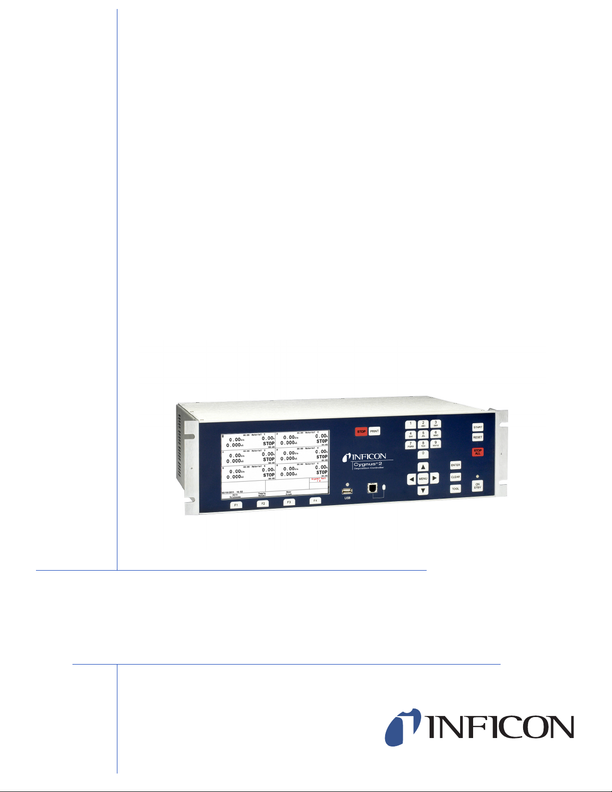
OPERATING MANUAL
®
Cygnus
Thin Film Deposition Controller
IPN 074-545-P1E
2
Page 2

Page 3

www.inficon.com reachus@inficon.com
©2012 INFICON
®
Title P
age
OPERATING MANUAL
®
Cygnus
2
Thin Film Deposition Controller
IPN 074-545-P1E
Page 4

Trademarks
The trademarks of the products mentioned in this Operating Manual are held by the companies that
produce them.
CAJON® is a registered trademark of Swagelok, Co.
INFICON®, RateWatcher™, and Cygnus® are trademarks of INFICON GmbH.
Kingston® is a registered trademark of Kingston Technology Corporation.
Lexar® is a registered trademark of Lexar Media, Inc.
Memorex® is a U.S. registered trademark of Memtek Corporation.
SanDisk® is a registered trademark of SanDisk Corporation.
Windows®, Windows 95® and Microsoft® are registered trademarks of Microsoft Corporation.
All other brand and product names are trademarks or registered trademarks of their respective companies.
Disclaimer
The information contained in this Operating Manual is believed to be accurate and reliable. However, INFICON
assumes no responsibility for its use and shall not be liable for any special, incidental, or consequential
damages related to the use of this product.
Due to our continuing program of product improvements, specifications are subject to change without notice.
Copyright
©2012 All rights reserved.
Reproduction or adaptation of any part of this document without permission is unlawful.
Page 5

DECLARATION OF CONFORMITY
This is to certify that this equipment, designed and manufactured by:
INFICON Inc.
Two Technology Place
East Syracuse, NY 13057
USA
meets the essential safety requirements of the European Union and is placed on the market
accordingly. It has been constructed in accordance with good engineering practice in safety
matters in force in the Community and does not endanger the safety of persons, domestic
animals or property when properly installed and maintained and used in applications for
which it was made.
Equipment Description: IC6/Cygnus 2 Deposition Controller (including all options).
Applicable Directives: 2006/95/EC (LVD)
2004/108/EC (General EMC)
2002/95/EC (RoHS)
Applicable Standards:
Safety: EN 61010-1:2001
Emissions: EN 61326-1:1997/A1: 1998/A2: 2001 (Radiated & Conducted Emissions)
Class A: Emissions per Table 3
(EMC – Measurement, Control & Laboratory Equipment)
Immunity: EN 61326-1:1997/A1: 1998/A2: 2001 (General EMC)
Class A: Immunity per Table A1
(EMC – Measurement, Control & Laboratory Equipment)
RoHS: Fully compliant
CE Implementation Date: June 2010 (Updated March, 2011)
Authorized Representative:
Steve Schill
INFICON Inc.
Thin Film Business Line Manager
ANY QUESTIONS RELATIVE TO THIS DECLARATION OR TO THE SAFETY OF INFICON'S PRODUCTS SHOULD BE DIRECTED, IN
WRITING, TO THE AUTHORIZED REPRESENTATIVE AT THE ABOVE ADDRESS.
Page 6

Page 7

Warranty
WARRANTY AND LIABILITY - LIMITATION: Seller warrants the products
manufactured by it, or by an affiliated company and sold by it, and described on
the reverse hereof, to be, for the period of warranty coverage specified below, free
from defects of materials or workmanship under normal proper use and service.
The period of warranty coverage is specified for the respective products in the
respective Seller instruction manuals for those products but shall not be less than
two (2) years from the date of shipment thereof by Seller. Seller's liability under
this warranty is limited to such of the above products or parts thereof as are
returned, transportation prepaid, to Seller's plant, not later than thirty (30) days
after the expiration of the period of warranty coverage in respect thereof and are
found by Seller's examination to have failed to function properly because of
defective workmanship or materials and not because of improper installation or
misuse and is limited to, at Seller's election, either (a) repairing and returning the
product or part thereof, or (b) furnishing a replacement product or part thereof,
transportation prepaid by Seller in either case. In the event Buyer discovers or
learns that a product does not conform to warranty, Buyer shall immediately notify
Seller in writing of such non-conformity, specifying in reasonable detail the nature
of such non-conformity. If Seller is not provided with such written notification,
Seller shall not be liable for any further damages which could have been avoided if
Seller had been provided with immediate written notification.
THIS WARRANTY IS MADE AND ACCEPTED IN LIEU OF ALL OTHER
WARRANTIES, EXPRESS OR IMPLIED, WHETHER OF MERCHANTABILITY OR
OF FITNESS FOR A PARTICULAR PURPOSE OR OTHERWISE, AS BUYER'S
EXCLUSIVE REMEDY FOR ANY DEFECTS IN THE PRODUCTS TO BE SOLD
HEREUNDER. All other obligations and liabilities of Seller, whether in contract or
tort (including negligence) or otherwise, are expressly EXCLUDED. In no event
shall Seller be liable for any costs, expenses or damages, whether direct or
indirect, special, incidental, consequential, or other, on any claim of any defective
product, in excess of the price paid by Buyer for the product plus return
transportation charges prepaid.
No warranty is made by Seller of any Seller product which has been installed,
used or operated contrary to Seller's written instruction manual or which has been
subjected to misuse, negligence or accident or has been repaired or altered by
anyone other than Seller or which has been used in a manner or for a purpose for
which the Seller product was not designed nor against any defects due to plans or
instructions supplied to Seller by or for Buyer.
This manual is intended for private use by INFICON® Inc. and its customers.
Contact INFICON before reproducing its contents.
NOTE: These instructions do not provide for every contingency that may arise in
connection with the installation, operation or maintenance of this equipment.
Should you require further assistance, please contact INFICON.
www.inficon.com reachus@inficon.com
Page 8

Page 9

Cygnus 2 Operating Manual
Table Of Contents
Cover Page
Title Page
Trademarks
Disclaimer
Copyright
Declaration Of Conformity
Warranty
Chapter 1
Introduction and Specifications
1.1 Introduction. . . . . . . . . . . . . . . . . . . . . . . . . . . . . . . . . . . . . . . . . . . . . . . . . . 1-1
1.2 Cygnus 2 Safety . . . . . . . . . . . . . . . . . . . . . . . . . . . . . . . . . . . . . . . . . . . . . .1-2
1.2.1 Definition of Notes, Cautions and Warnings. . . . . . . . . . . . . . . . . . . . . . . . .1-2
1.2.2 General Safety Information. . . . . . . . . . . . . . . . . . . . . . . . . . . . . . . . . . . . . . 1-3
1.2.3 Earth Ground . . . . . . . . . . . . . . . . . . . . . . . . . . . . . . . . . . . . . . . . . . . . . . . .1-4
1.2.4 Main Power Connection . . . . . . . . . . . . . . . . . . . . . . . . . . . . . . . . . . . . . . . . 1-5
1.3 How To Contact INFICON . . . . . . . . . . . . . . . . . . . . . . . . . . . . . . . . . . . . . . 1-6
1.3.1 Returning Your Cygnus 2 . . . . . . . . . . . . . . . . . . . . . . . . . . . . . . . . . . . . . . . 1-6
1.4 Cygnus 2 Specifications . . . . . . . . . . . . . . . . . . . . . . . . . . . . . . . . . . . . . . . .1-7
1.4.1 Measurement . . . . . . . . . . . . . . . . . . . . . . . . . . . . . . . . . . . . . . . . . . . . . . . .1-7
1.4.2 Screens and Hierarchy . . . . . . . . . . . . . . . . . . . . . . . . . . . . . . . . . . . . . . . . . 1-7
1.4.3 Cygnus 2 Features . . . . . . . . . . . . . . . . . . . . . . . . . . . . . . . . . . . . . . . . . . . . 1-8
1.4.3.1 Recipe Storage & Datalogging . . . . . . . . . . . . . . . . . . . . . . . . . . . . . . . . . . . 1-8
1.4.3.2 Sensor Parameters. . . . . . . . . . . . . . . . . . . . . . . . . . . . . . . . . . . . . . . . . . . .1-8
1.4.3.3 Source Parameters. . . . . . . . . . . . . . . . . . . . . . . . . . . . . . . . . . . . . . . . . . . .1-8
IPN 074-545-P1E
1.4.3.4 Material Parameters . . . . . . . . . . . . . . . . . . . . . . . . . . . . . . . . . . . . . . . . . . .1-9
1.4.3.5 General Global Parameters . . . . . . . . . . . . . . . . . . . . . . . . . . . . . . . . . . . .1-11
1.4.4 ‘Display . . . . . . . . . . . . . . . . . . . . . . . . . . . . . . . . . . . . . . . . . . . . . . . . . . . .1-12
1.4.5 DAC Outputs . . . . . . . . . . . . . . . . . . . . . . . . . . . . . . . . . . . . . . . . . . . . . . . 1-13
1.4.6 Logic Processing . . . . . . . . . . . . . . . . . . . . . . . . . . . . . . . . . . . . . . . . . . . . 1-14
1.4.7 Relays / Inputs . . . . . . . . . . . . . . . . . . . . . . . . . . . . . . . . . . . . . . . . . . . . . .1-14
1.4.8 Remote Communications . . . . . . . . . . . . . . . . . . . . . . . . . . . . . . . . . . . . . . 1-15
1.4.9 Accessories . . . . . . . . . . . . . . . . . . . . . . . . . . . . . . . . . . . . . . . . . . . . . . . . 1-15
1.4.10 Power . . . . . . . . . . . . . . . . . . . . . . . . . . . . . . . . . . . . . . . . . . . . . . . . . . . . . 1-15
1.4.11 Operating Environment. . . . . . . . . . . . . . . . . . . . . . . . . . . . . . . . . . . . . . . .1-15
1.4.12 Storage Temperature . . . . . . . . . . . . . . . . . . . . . . . . . . . . . . . . . . . . . . . . . 1-15
TOC - 1
Page 10

Cygnus 2 Operating Manual
1.4.13 Warm Up Period. . . . . . . . . . . . . . . . . . . . . . . . . . . . . . . . . . . . . . . . . . . . . 1-15
1.4.14 Size . . . . . . . . . . . . . . . . . . . . . . . . . . . . . . . . . . . . . . . . . . . . . . . . . . . . . . 1-16
1.4.15 Installation Clearance Requirements . . . . . . . . . . . . . . . . . . . . . . . . . . . . . 1-16
1.4.15.1 Connector Clearances:. . . . . . . . . . . . . . . . . . . . . . . . . . . . . . . . . . . . . . . . 1-16
1.4.15.2 Cooling Clearances:. . . . . . . . . . . . . . . . . . . . . . . . . . . . . . . . . . . . . . . . . . 1-16
1.4.16 Weight . . . . . . . . . . . . . . . . . . . . . . . . . . . . . . . . . . . . . . . . . . . . . . . . . . . . 1-16
1.4.17 Cleaning . . . . . . . . . . . . . . . . . . . . . . . . . . . . . . . . . . . . . . . . . . . . . . . . . . . 1-16
1.5 Unpacking and Inspection . . . . . . . . . . . . . . . . . . . . . . . . . . . . . . . . . . . . . 1-17
1.6 Parts and Options Overview. . . . . . . . . . . . . . . . . . . . . . . . . . . . . . . . . . . . 1-17
1.6.1 Base Configurations . . . . . . . . . . . . . . . . . . . . . . . . . . . . . . . . . . . . . . . . . . 1-17
1.6.2 Pre-installed Options or Spares . . . . . . . . . . . . . . . . . . . . . . . . . . . . . . . . . 1-17
1.6.3 Optional Accessories . . . . . . . . . . . . . . . . . . . . . . . . . . . . . . . . . . . . . . . . . 1-18
1.6.4 Oscillator Packages . . . . . . . . . . . . . . . . . . . . . . . . . . . . . . . . . . . . . . . . . . 1-18
1.6.5 Sensors . . . . . . . . . . . . . . . . . . . . . . . . . . . . . . . . . . . . . . . . . . . . . . . . . . . 1-18
1.6.6 Replacement Cables . . . . . . . . . . . . . . . . . . . . . . . . . . . . . . . . . . . . . . . . . 1-18
1.7 Initial Power-On Verification. . . . . . . . . . . . . . . . . . . . . . . . . . . . . . . . . . . . 1-19
Chapter 2
Installation and Interfaces
2.1 Location Guidelines . . . . . . . . . . . . . . . . . . . . . . . . . . . . . . . . . . . . . . . . . . . 2-1
2.1.1 Sensor Types . . . . . . . . . . . . . . . . . . . . . . . . . . . . . . . . . . . . . . . . . . . . . . . . 2-1
2.1.2 Sensor Installation . . . . . . . . . . . . . . . . . . . . . . . . . . . . . . . . . . . . . . . . . . . . 2-1
2.1.3 Cygnus 2 Installation . . . . . . . . . . . . . . . . . . . . . . . . . . . . . . . . . . . . . . . . . . 2-4
2.2 Avoiding Electrical Interference . . . . . . . . . . . . . . . . . . . . . . . . . . . . . . . . . . 2-4
2.2.1 Verifying/Establishing Earth Ground . . . . . . . . . . . . . . . . . . . . . . . . . . . . . . 2-4
2.2.2 Connections to Earth Ground. . . . . . . . . . . . . . . . . . . . . . . . . . . . . . . . . . . . 2-5
2.2.3 Minimizing Noise Pickup From External Cabling . . . . . . . . . . . . . . . . . . . . . 2-6
2.3 Connecting the Controller. . . . . . . . . . . . . . . . . . . . . . . . . . . . . . . . . . . . . . . 2-7
2.3.1 Routing XIU Cables . . . . . . . . . . . . . . . . . . . . . . . . . . . . . . . . . . . . . . . . . . . 2-7
2.3.2 Interface Cable Fabrication and Pin-Out . . . . . . . . . . . . . . . . . . . . . . . . . . . 2-7
2.3.2.1 Source Control Connection . . . . . . . . . . . . . . . . . . . . . . . . . . . . . . . . . . . . . 2-8
2.3.2.2 Crucible Indexer Connections . . . . . . . . . . . . . . . . . . . . . . . . . . . . . . . . . . . 2-8
2.3.2.3 DAC Option Kit. . . . . . . . . . . . . . . . . . . . . . . . . . . . . . . . . . . . . . . . . . . . . . . 2-8
2.3.2.4 I/O Expansion Options . . . . . . . . . . . . . . . . . . . . . . . . . . . . . . . . . . . . . . . . . 2-9
2.3.2.5 RS-232C Communications. . . . . . . . . . . . . . . . . . . . . . . . . . . . . . . . . . . . . 2-11
2.3.2.6 Isolated +24 V (dc) Supply. . . . . . . . . . . . . . . . . . . . . . . . . . . . . . . . . . . . . 2-12
IPN 074-545-P1E
TOC - 2
Page 11

Cygnus 2 Operating Manual
Chapter 3
Operation
3.1 Front Panel Controls. . . . . . . . . . . . . . . . . . . . . . . . . . . . . . . . . . . . . . . . . . .3-1
3.2 Rear Panel Interfaces. . . . . . . . . . . . . . . . . . . . . . . . . . . . . . . . . . . . . . . . . .3-3
3.3 Displays . . . . . . . . . . . . . . . . . . . . . . . . . . . . . . . . . . . . . . . . . . . . . . . . . . . . 3-5
3.3.1 Main Menu Display . . . . . . . . . . . . . . . . . . . . . . . . . . . . . . . . . . . . . . . . . . . .3-5
3.3.2 Operate. . . . . . . . . . . . . . . . . . . . . . . . . . . . . . . . . . . . . . . . . . . . . . . . . . . . .3-6
3.3.3 Sensor Information . . . . . . . . . . . . . . . . . . . . . . . . . . . . . . . . . . . . . . . . . . . . 3-8
3.3.3.1 Sensor Information Rate/Xtal Display Description . . . . . . . . . . . . . . . . . . . .3-8
3.3.3.2 Crystal Life and Starting Frequency . . . . . . . . . . . . . . . . . . . . . . . . . . . . . .3-10
3.3.3.3 Function Key Selection Choices. . . . . . . . . . . . . . . . . . . . . . . . . . . . . . . . . 3-10
3.3.3.4 Sensor Information Type/Freq Display Description . . . . . . . . . . . . . . . . . . 3-11
3.3.3.4.1 TEST XIU . . . . . . . . . . . . . . . . . . . . . . . . . . . . . . . . . . . . . . . . . . . . . . . . . . 3-12
3.3.4 Sensor Screen . . . . . . . . . . . . . . . . . . . . . . . . . . . . . . . . . . . . . . . . . . . . . .3-13
3.3.5 Source . . . . . . . . . . . . . . . . . . . . . . . . . . . . . . . . . . . . . . . . . . . . . . . . . . . . 3-14
3.3.6 Material. . . . . . . . . . . . . . . . . . . . . . . . . . . . . . . . . . . . . . . . . . . . . . . . . . . .3-15
3.3.6.1 Overview Page . . . . . . . . . . . . . . . . . . . . . . . . . . . . . . . . . . . . . . . . . . . . . .3-15
3.3.6.2 Source Page. . . . . . . . . . . . . . . . . . . . . . . . . . . . . . . . . . . . . . . . . . . . . . . . 3-15
3.3.6.3 Sensor Page. . . . . . . . . . . . . . . . . . . . . . . . . . . . . . . . . . . . . . . . . . . . . . . . 3-16
3.3.6.4 Pre/Post Page . . . . . . . . . . . . . . . . . . . . . . . . . . . . . . . . . . . . . . . . . . . . . . 3-16
3.3.6.5 Deposit Page . . . . . . . . . . . . . . . . . . . . . . . . . . . . . . . . . . . . . . . . . . . . . . . 3-16
3.3.6.6 Lib A-Hf, Lib Hf-Sc, Lib Sc-Z Sub-Displays . . . . . . . . . . . . . . . . . . . . . . . . 3-17
3.3.7 General. . . . . . . . . . . . . . . . . . . . . . . . . . . . . . . . . . . . . . . . . . . . . . . . . . . .3-17
3.3.7.1 Process Page . . . . . . . . . . . . . . . . . . . . . . . . . . . . . . . . . . . . . . . . . . . . . . .3-17
3.3.7.2 DACs Page. . . . . . . . . . . . . . . . . . . . . . . . . . . . . . . . . . . . . . . . . . . . . . . . . 3-17
3.3.7.3 Comm Page . . . . . . . . . . . . . . . . . . . . . . . . . . . . . . . . . . . . . . . . . . . . . . . .3-18
3.3.7.4 Message Page . . . . . . . . . . . . . . . . . . . . . . . . . . . . . . . . . . . . . . . . . . . . . .3-18
3.3.7.5 Date/Time Page . . . . . . . . . . . . . . . . . . . . . . . . . . . . . . . . . . . . . . . . . . . . .3-18
IPN 074-545-P1E
3.3.7.6 Test Page . . . . . . . . . . . . . . . . . . . . . . . . . . . . . . . . . . . . . . . . . . . . . . . . . .3-18
3.3.7.7 Lock Page. . . . . . . . . . . . . . . . . . . . . . . . . . . . . . . . . . . . . . . . . . . . . . . . . .3-18
3.3.7.8 Audio/Visual Page . . . . . . . . . . . . . . . . . . . . . . . . . . . . . . . . . . . . . . . . . . .3-18
3.3.8 Digital I/O . . . . . . . . . . . . . . . . . . . . . . . . . . . . . . . . . . . . . . . . . . . . . . . . . .3-19
3.3.9 Logic . . . . . . . . . . . . . . . . . . . . . . . . . . . . . . . . . . . . . . . . . . . . . . . . . . . . . .3-20
3.3.10 Maintenance. . . . . . . . . . . . . . . . . . . . . . . . . . . . . . . . . . . . . . . . . . . . . . . . 3-20
3.3.11 Counter / Timer. . . . . . . . . . . . . . . . . . . . . . . . . . . . . . . . . . . . . . . . . . . . . .3-20
3.3.12 USB Storage. . . . . . . . . . . . . . . . . . . . . . . . . . . . . . . . . . . . . . . . . . . . . . . .3-20
3.3.13 Programming Guidelines . . . . . . . . . . . . . . . . . . . . . . . . . . . . . . . . . . . . . . 3-20
3.4 State Descriptions . . . . . . . . . . . . . . . . . . . . . . . . . . . . . . . . . . . . . . . . . . . 3-23
TOC - 3
Page 12

Cygnus 2 Operating Manual
3.5 Special Features . . . . . . . . . . . . . . . . . . . . . . . . . . . . . . . . . . . . . . . . . . . . 3-25
3.5.1 Crystal Switching . . . . . . . . . . . . . . . . . . . . . . . . . . . . . . . . . . . . . . . . . . . . 3-25
3.5.1.1 XtalTwo (CrystalTwo). . . . . . . . . . . . . . . . . . . . . . . . . . . . . . . . . . . . . . . . . 3-26
3.5.1.2 XtalSix (CrystalSix). . . . . . . . . . . . . . . . . . . . . . . . . . . . . . . . . . . . . . . . . . . 3-27
3.5.1.3 Xtal12 (Crystal12). . . . . . . . . . . . . . . . . . . . . . . . . . . . . . . . . . . . . . . . . . . . 3-27
3.5.1.4 Generic Sensor Crystal Switching . . . . . . . . . . . . . . . . . . . . . . . . . . . . . . . 3-28
3.5.2 Source/Crucible Selection . . . . . . . . . . . . . . . . . . . . . . . . . . . . . . . . . . . . . 3-28
3.5.2.1 Example: Programming Turret Source Crucible Selection. . . . . . . . . . . . . 3-29
3.5.3 Auto-Z. . . . . . . . . . . . . . . . . . . . . . . . . . . . . . . . . . . . . . . . . . . . . . . . . . . . . 3-29
3.5.4 Rate Watcher . . . . . . . . . . . . . . . . . . . . . . . . . . . . . . . . . . . . . . . . . . . . . . . 3-31
3.5.5 Handheld Controller . . . . . . . . . . . . . . . . . . . . . . . . . . . . . . . . . . . . . . . . . . 3-31
3.5.5.1 Determining Soak Power with the Handheld Controller . . . . . . . . . . . . . . . 3-32
3.5.6 Test Mode . . . . . . . . . . . . . . . . . . . . . . . . . . . . . . . . . . . . . . . . . . . . . . . . . 3-32
3.5.6.1 Standard or Time Compressed . . . . . . . . . . . . . . . . . . . . . . . . . . . . . . . . . 3-32
3.5.6.2 Advanced Test . . . . . . . . . . . . . . . . . . . . . . . . . . . . . . . . . . . . . . . . . . . . . . 3-32
3.5.7 USB Storage Device . . . . . . . . . . . . . . . . . . . . . . . . . . . . . . . . . . . . . . . . . 3-33
3.5.8 Lock and Access Codes. . . . . . . . . . . . . . . . . . . . . . . . . . . . . . . . . . . . . . . 3-34
3.5.9 Datalog . . . . . . . . . . . . . . . . . . . . . . . . . . . . . . . . . . . . . . . . . . . . . . . . . . . . 3-35
3.5.9.1 Datalog contents: . . . . . . . . . . . . . . . . . . . . . . . . . . . . . . . . . . . . . . . . . . . . 3-36
3.5.9.2 Page Format ASCII Example: . . . . . . . . . . . . . . . . . . . . . . . . . . . . . . . . . . 3-38
3.5.9.3 Comma Format ASCII Example to USB Storage Device: . . . . . . . . . . . . . 3-39
3.5.10 DAC Monitoring . . . . . . . . . . . . . . . . . . . . . . . . . . . . . . . . . . . . . . . . . . . . . 3-40
3.5.11 Trend Analysis . . . . . . . . . . . . . . . . . . . . . . . . . . . . . . . . . . . . . . . . . . . . . . 3-40
3.5.11.1 Cygnus 2 Parameters Associated with the Trend Analysis Feature . . . . . 3-40
Chapter 4
Sensor & Source Set-Up
4.1 Sensor Set-Up Introduction . . . . . . . . . . . . . . . . . . . . . . . . . . . . . . . . . . . . . 4-1
4.1.1 Sensor Display Navigation . . . . . . . . . . . . . . . . . . . . . . . . . . . . . . . . . . . . . . 4-1
4.1.2 Sensor Parameters . . . . . . . . . . . . . . . . . . . . . . . . . . . . . . . . . . . . . . . . . . . 4-2
4.2 Source Set-Up Introduction . . . . . . . . . . . . . . . . . . . . . . . . . . . . . . . . . . . . . 4-4
4.2.1 Source Navigation . . . . . . . . . . . . . . . . . . . . . . . . . . . . . . . . . . . . . . . . . . . . 4-4
4.2.2 Source Parameters . . . . . . . . . . . . . . . . . . . . . . . . . . . . . . . . . . . . . . . . . . . 4-5
4.3 DAC Output Selection Rules . . . . . . . . . . . . . . . . . . . . . . . . . . . . . . . . . . . . 4-7
Chapter 5
Material Set-Up
5.1 Introduction. . . . . . . . . . . . . . . . . . . . . . . . . . . . . . . . . . . . . . . . . . . . . . . . . . 5-1
5.1.1 Material Overview Page . . . . . . . . . . . . . . . . . . . . . . . . . . . . . . . . . . . . . . . . 5-1
5.1.2 Material Definition. . . . . . . . . . . . . . . . . . . . . . . . . . . . . . . . . . . . . . . . . . . . . 5-2
IPN 074-545-P1E
TOC - 4
Page 13

5.1.3 Material Source Page Parameters . . . . . . . . . . . . . . . . . . . . . . . . . . . . . . . . 5-3
5.1.4 Material Sensor Parameters Page . . . . . . . . . . . . . . . . . . . . . . . . . . . . . . . .5-7
5.1.5 Pre/Post Screen Deposit Page Parameters . . . . . . . . . . . . . . . . . . . . . . . . 5-10
5.1.6 Post Deposit Parameters . . . . . . . . . . . . . . . . . . . . . . . . . . . . . . . . . . . . . . 5-13
5.1.7 Deposit Page Parameters . . . . . . . . . . . . . . . . . . . . . . . . . . . . . . . . . . . . .5-14
5.2 Special Material Parameter Features. . . . . . . . . . . . . . . . . . . . . . . . . . . . . 5-17
5.2.1 Skip Deposit . . . . . . . . . . . . . . . . . . . . . . . . . . . . . . . . . . . . . . . . . . . . . . . . 5-17
5.2.2 RateWatcher™ Sample and Hold Feature . . . . . . . . . . . . . . . . . . . . . . . . . 5-17
Chapter 6
6.1 General Set-Up Overview. . . . . . . . . . . . . . . . . . . . . . . . . . . . . . . . . . . . . . .6-1
6.2 General Process Page . . . . . . . . . . . . . . . . . . . . . . . . . . . . . . . . . . . . . . . . . 6-1
6.3 DACs Page Parameters . . . . . . . . . . . . . . . . . . . . . . . . . . . . . . . . . . . . . . . .6-2
6.4 COMM Page Parameters . . . . . . . . . . . . . . . . . . . . . . . . . . . . . . . . . . . . . . . 6-3
6.5 MESSAGE Page Set-up. . . . . . . . . . . . . . . . . . . . . . . . . . . . . . . . . . . . . . . .6-5
6.6 DATE / TIME Set Up . . . . . . . . . . . . . . . . . . . . . . . . . . . . . . . . . . . . . . . . . . 6-6
6.7 TEST Page Set Up. . . . . . . . . . . . . . . . . . . . . . . . . . . . . . . . . . . . . . . . . . . . 6-7
6.8 LOCK Page Code Set-up . . . . . . . . . . . . . . . . . . . . . . . . . . . . . . . . . . . . . . .6-8
6.9 AUDIO / VISUAL Page Set Up. . . . . . . . . . . . . . . . . . . . . . . . . . . . . . . . . . . 6-9
Cygnus 2 Operating Manual
General Parameters
Chapter 7
Digital I/O
7.1 Digital I/O Screen . . . . . . . . . . . . . . . . . . . . . . . . . . . . . . . . . . . . . . . . . . . . . 7-1
7.2 All Input Page . . . . . . . . . . . . . . . . . . . . . . . . . . . . . . . . . . . . . . . . . . . . . . . .7-1
7.3 All Output Page . . . . . . . . . . . . . . . . . . . . . . . . . . . . . . . . . . . . . . . . . . . . . . 7-2
7.4 I/O Board Page. . . . . . . . . . . . . . . . . . . . . . . . . . . . . . . . . . . . . . . . . . . . . . .7-3
7.4.1 Output Type . . . . . . . . . . . . . . . . . . . . . . . . . . . . . . . . . . . . . . . . . . . . . . . . .7-3
Chapter 8
IPN 074-545-P1E
8.1 Logic Statement Overview . . . . . . . . . . . . . . . . . . . . . . . . . . . . . . . . . . . . . .8-1
8.2 Editing the Logic Statements . . . . . . . . . . . . . . . . . . . . . . . . . . . . . . . . . . . . 8-2
8.2.1 Logic Statement Groups. . . . . . . . . . . . . . . . . . . . . . . . . . . . . . . . . . . . . . . .8-3
8.2.2 Logic Statement Editing . . . . . . . . . . . . . . . . . . . . . . . . . . . . . . . . . . . . . . . .8-4
8.2.3 AND/OR and ON Logic Connectors . . . . . . . . . . . . . . . . . . . . . . . . . . . . . . . 8-6
8.2.3.1 ON Operator. . . . . . . . . . . . . . . . . . . . . . . . . . . . . . . . . . . . . . . . . . . . . . . . .8-6
8.3 IF Event Definitions . . . . . . . . . . . . . . . . . . . . . . . . . . . . . . . . . . . . . . . . . . . 8-7
8.4 THEN Action Definitions. . . . . . . . . . . . . . . . . . . . . . . . . . . . . . . . . . . . . . . 8-14
8.5 Logic Statement Example. . . . . . . . . . . . . . . . . . . . . . . . . . . . . . . . . . . . . .8-17
Logic Statement Set-Up
TOC - 5
Page 14

Cygnus 2 Operating Manual
Chapter 9
Remote Communications
9.1 Remote Communication Configuration Overview . . . . . . . . . . . . . . . . . . . . 9-1
9.2 Physical Connections. . . . . . . . . . . . . . . . . . . . . . . . . . . . . . . . . . . . . . . . . . 9-1
9.2.1 RS-232C Serial Port. . . . . . . . . . . . . . . . . . . . . . . . . . . . . . . . . . . . . . . . . . . 9-1
9.2.2 TCP/IP Ethernet Port . . . . . . . . . . . . . . . . . . . . . . . . . . . . . . . . . . . . . . . . . . 9-2
9.2.2.1 Network Connection. . . . . . . . . . . . . . . . . . . . . . . . . . . . . . . . . . . . . . . . . . . 9-2
9.2.2.2 How to Set Up the Network Protocol on the PC. . . . . . . . . . . . . . . . . . . . . . 9-2
9.3 Message Format . . . . . . . . . . . . . . . . . . . . . . . . . . . . . . . . . . . . . . . . . . . . . 9-5
9.3.1 Protocol . . . . . . . . . . . . . . . . . . . . . . . . . . . . . . . . . . . . . . . . . . . . . . . . . . . . 9-5
9.3.1.1 Command Packet (Host to Cygnus 2 Message) . . . . . . . . . . . . . . . . . . . . . 9-5
9.3.1.2 Data Type Codes . . . . . . . . . . . . . . . . . . . . . . . . . . . . . . . . . . . . . . . . . . . . . 9-7
9.3.1.3 Response Packet (Cygnus 2 to Host Message). . . . . . . . . . . . . . . . . . . . . . 9-8
9.3.1.4 Timeouts. . . . . . . . . . . . . . . . . . . . . . . . . . . . . . . . . . . . . . . . . . . . . . . . . . . 9-10
9.4 Communication Commands. . . . . . . . . . . . . . . . . . . . . . . . . . . . . . . . . . . . 9-10
9.4.1 Query and Update Commands. . . . . . . . . . . . . . . . . . . . . . . . . . . . . . . . . . 9-10
9.4.2 Status Commands . . . . . . . . . . . . . . . . . . . . . . . . . . . . . . . . . . . . . . . . . . . 9-11
9.4.3 HELLO Command . . . . . . . . . . . . . . . . . . . . . . . . . . . . . . . . . . . . . . . . . . . 9-11
9.4.4 Query General Parameter . . . . . . . . . . . . . . . . . . . . . . . . . . . . . . . . . . . . . 9-11
9.4.5 Update General Parameter . . . . . . . . . . . . . . . . . . . . . . . . . . . . . . . . . . . . 9-12
9.4.6 Query Material Parameter . . . . . . . . . . . . . . . . . . . . . . . . . . . . . . . . . . . . . 9-16
9.4.7 Update Material Parameter . . . . . . . . . . . . . . . . . . . . . . . . . . . . . . . . . . . . 9-16
9.4.8 Query Sensor Parameter . . . . . . . . . . . . . . . . . . . . . . . . . . . . . . . . . . . . . . 9-21
9.4.9 Update Sensor Parameter . . . . . . . . . . . . . . . . . . . . . . . . . . . . . . . . . . . . . 9-21
9.4.10 Query Source Parameter . . . . . . . . . . . . . . . . . . . . . . . . . . . . . . . . . . . . . . 9-22
9.4.11 Update Source Parameter . . . . . . . . . . . . . . . . . . . . . . . . . . . . . . . . . . . . . 9-22
9.4.12 Query Process Material Parameter . . . . . . . . . . . . . . . . . . . . . . . . . . . . . . 9-24
9.4.13 Update Process Material Parameter . . . . . . . . . . . . . . . . . . . . . . . . . . . . . 9-24
9.4.14 Query Material Name . . . . . . . . . . . . . . . . . . . . . . . . . . . . . . . . . . . . . . . . . 9-25
9.4.15 Update Material Name . . . . . . . . . . . . . . . . . . . . . . . . . . . . . . . . . . . . . . . . 9-25
9.4.16 Query Input Name . . . . . . . . . . . . . . . . . . . . . . . . . . . . . . . . . . . . . . . . . . . 9-25
9.4.17 Update Input Name . . . . . . . . . . . . . . . . . . . . . . . . . . . . . . . . . . . . . . . . . . 9-25
9.4.18 Query Output Name . . . . . . . . . . . . . . . . . . . . . . . . . . . . . . . . . . . . . . . . . . 9-25
9.4.19 Update Output Name . . . . . . . . . . . . . . . . . . . . . . . . . . . . . . . . . . . . . . . . . 9-26
9.4.20 Query Output Type. . . . . . . . . . . . . . . . . . . . . . . . . . . . . . . . . . . . . . . . . . . 9-26
9.4.21 Update Output Type. . . . . . . . . . . . . . . . . . . . . . . . . . . . . . . . . . . . . . . . . . 9-26
9.4.22 Query User Message . . . . . . . . . . . . . . . . . . . . . . . . . . . . . . . . . . . . . . . . . 9-26
9.4.23 Update User Message . . . . . . . . . . . . . . . . . . . . . . . . . . . . . . . . . . . . . . . . 9-27
9.4.24 Query Logic Statement. . . . . . . . . . . . . . . . . . . . . . . . . . . . . . . . . . . . . . . . 9-27
9.4.25 Update Logic Statement. . . . . . . . . . . . . . . . . . . . . . . . . . . . . . . . . . . . . . . 9-29
IPN 074-545-P1E
TOC - 6
Page 15

Cygnus 2 Operating Manual
9.4.26 Cygnus 2 Event List . . . . . . . . . . . . . . . . . . . . . . . . . . . . . . . . . . . . . . . . . .9-29
9.4.27 Cygnus 2 Action List. . . . . . . . . . . . . . . . . . . . . . . . . . . . . . . . . . . . . . . . . . 9-33
9.4.28 Status General . . . . . . . . . . . . . . . . . . . . . . . . . . . . . . . . . . . . . . . . . . . . . .9-35
9.4.29 Status Material . . . . . . . . . . . . . . . . . . . . . . . . . . . . . . . . . . . . . . . . . . . . . .9-38
9.4.30 Status Sensor. . . . . . . . . . . . . . . . . . . . . . . . . . . . . . . . . . . . . . . . . . . . . . . 9-40
9.4.31 Remote General Action . . . . . . . . . . . . . . . . . . . . . . . . . . . . . . . . . . . . . . . 9-42
9.4.32 Remote Material Action . . . . . . . . . . . . . . . . . . . . . . . . . . . . . . . . . . . . . . .9-45
9.4.33 Cygnus 2 Communications Examples . . . . . . . . . . . . . . . . . . . . . . . . . . . . 9-47
9.4.33.1 General Command Packet Format. . . . . . . . . . . . . . . . . . . . . . . . . . . . . . .9-47
9.4.33.2 General Response Packet Format . . . . . . . . . . . . . . . . . . . . . . . . . . . . . . .9-47
9.4.33.3 HELLO Command, ASCII name and version . . . . . . . . . . . . . . . . . . . . . . . 9-47
9.4.33.4 Query Material Parameter, Z-Ratio (2), Material 1 . . . . . . . . . . . . . . . . . . . 9-48
9.4.33.5 Update Material Parameter, Control Loop (4), Material 1, PID (2) . . . . . . . 9-48
9.4.33.6 Query Sensor Parameter, Shutter Output (1), Sensor 1 . . . . . . . . . . . . . . 9-48
9.4.33.7 Update Sensor Parameter, Sensor Type (2), Sensor 1,
CrystalTwo (1) . . . . . . . . . . . . . . . . . . . . . . . . . . . . . . . . . . . . . . . . . . . . . .9-48
9.4.33.8 Query Source Parameter, Shutter Output (2), Source 1 . . . . . . . . . . . . . . 9-48
9.4.33.9 Update Source Parameter, Number of crucibles (3),
Source 1, 4 crucibles (1). . . . . . . . . . . . . . . . . . . . . . . . . . . . . . . . . . . . . . .9-48
9.4.33.10 Query Material Name, Material 1 . . . . . . . . . . . . . . . . . . . . . . . . . . . . . . . .9-49
9.4.33.11 Update Material Name, Material 1, “SILVER”. . . . . . . . . . . . . . . . . . . . . . .9-49
9.4.33.12 Query Input Name, Input 1 . . . . . . . . . . . . . . . . . . . . . . . . . . . . . . . . . . . . .9-49
9.4.33.13 Update Input Name, Input 1, “P1”. . . . . . . . . . . . . . . . . . . . . . . . . . . . . . . .9-49
9.4.33.14 Query Output Name, Output 1 . . . . . . . . . . . . . . . . . . . . . . . . . . . . . . . . . .9-49
9.4.33.15 Update Output Name, Output 1, “SHUTTER” . . . . . . . . . . . . . . . . . . . . . . 9-49
9.4.33.16 Query Output Type, Output 1 . . . . . . . . . . . . . . . . . . . . . . . . . . . . . . . . . . .9-50
9.4.33.17 Update Output Type, Output 1, Normally Closed (1) . . . . . . . . . . . . . . . . .9-50
9.4.33.18 Query User Message, Message 1 . . . . . . . . . . . . . . . . . . . . . . . . . . . . . . . 9-50
IPN 074-545-P1E
9.4.33.19 Update User Message, Message 1, “HELLO!”. . . . . . . . . . . . . . . . . . . . . . 9-50
9.4.33.20 Query Logic Statement, Statement 1 . . . . . . . . . . . . . . . . . . . . . . . . . . . . . 9-50
9.4.33.21 Update Logic statement, Statement 1,
“IF External Input 1 THEN Start 1” . . . . . . . . . . . . . . . . . . . . . . . . . . . . . . . 9-51
9.4.33.22 Status Material, Thickness (4), Material 1 . . . . . . . . . . . . . . . . . . . . . . . . . 9-52
9.4.33.23 Status Sensor, Crystal Life (0), Sensor 1 . . . . . . . . . . . . . . . . . . . . . . . . . . 9-52
9.4.33.24 Remote General Action, Stop All . . . . . . . . . . . . . . . . . . . . . . . . . . . . . . . .9-52
9.4.33.25 Remote Material Action, Open Source Shutter (8). . . . . . . . . . . . . . . . . . . 9-52
9.4.33.26 Example for Interpreting Float Responses . . . . . . . . . . . . . . . . . . . . . . . . . 9-53
TOC - 7
Page 16

Cygnus 2 Operating Manual
Chapter 10
Maintenance and Calibration Procedures
10.1 Importance of Density, Tooling and Z-Ratio. . . . . . . . . . . . . . . . . . . . . . . . 10-1
10.2 Determining Density. . . . . . . . . . . . . . . . . . . . . . . . . . . . . . . . . . . . . . . . . . 10-1
10.3 Determining Tooling . . . . . . . . . . . . . . . . . . . . . . . . . . . . . . . . . . . . . . . . . . 10-2
10.4 Laboratory Determination of Z-Ratio . . . . . . . . . . . . . . . . . . . . . . . . . . . . . 10-3
10.5 Source Maintenance . . . . . . . . . . . . . . . . . . . . . . . . . . . . . . . . . . . . . . . . . 10-5
10.5.1 Source Maintenance Parameters. . . . . . . . . . . . . . . . . . . . . . . . . . . . . . . . 10-6
10.5.1.1 Crucible Rotation . . . . . . . . . . . . . . . . . . . . . . . . . . . . . . . . . . . . . . . . . . . . 10-6
10.5.1.2 Toggle Sensor and Source Shutter . . . . . . . . . . . . . . . . . . . . . . . . . . . . . . 10-6
10.5.1.3 Start/Stop Manual Power . . . . . . . . . . . . . . . . . . . . . . . . . . . . . . . . . . . . . . 10-6
10.6 System Status . . . . . . . . . . . . . . . . . . . . . . . . . . . . . . . . . . . . . . . . . . . . . . 10-7
Chapter 11
Counters & Timers
11.1 Introduction. . . . . . . . . . . . . . . . . . . . . . . . . . . . . . . . . . . . . . . . . . . . . . . . . 11-1
Chapter 12
12.1 File Handling (USB) . . . . . . . . . . . . . . . . . . . . . . . . . . . . . . . . . . . . . . . . . . 12-1
12.1.1 USB Storage Devices. . . . . . . . . . . . . . . . . . . . . . . . . . . . . . . . . . . . . . . . . 12-1
12.2 Directory Structure . . . . . . . . . . . . . . . . . . . . . . . . . . . . . . . . . . . . . . . . . . . 12-1
12.3 Configuration Files . . . . . . . . . . . . . . . . . . . . . . . . . . . . . . . . . . . . . . . . . . . 12-2
12.4 Data Logs. . . . . . . . . . . . . . . . . . . . . . . . . . . . . . . . . . . . . . . . . . . . . . . . . . 12-3
12.5 Screen Captures . . . . . . . . . . . . . . . . . . . . . . . . . . . . . . . . . . . . . . . . . . . . 12-4
Chapter 13
13.1 Status Messages . . . . . . . . . . . . . . . . . . . . . . . . . . . . . . . . . . . . . . . . . . . . 13-1
13.2 User Messages . . . . . . . . . . . . . . . . . . . . . . . . . . . . . . . . . . . . . . . . . . . . . 13-4
13.3 STOP messages . . . . . . . . . . . . . . . . . . . . . . . . . . . . . . . . . . . . . . . . . . . . 13-5
13.4 Transient Messages. . . . . . . . . . . . . . . . . . . . . . . . . . . . . . . . . . . . . . . . . . 13-6
13.5 Input Error Messages. . . . . . . . . . . . . . . . . . . . . . . . . . . . . . . . . . . . . . . . 13-10
13.6 Troubleshooting Guide. . . . . . . . . . . . . . . . . . . . . . . . . . . . . . . . . . . . . . . 13-11
13.6.1 Troubleshooting the Cygnus 2 . . . . . . . . . . . . . . . . . . . . . . . . . . . . . . . . . 13-12
13.6.2 Troubleshooting Transducers/Sensors . . . . . . . . . . . . . . . . . . . . . . . . . . 13-15
13.6.3 Troubleshooting Computer Communications. . . . . . . . . . . . . . . . . . . . . . 13-19
13.7 Replacing the Crystal . . . . . . . . . . . . . . . . . . . . . . . . . . . . . . . . . . . . . . . . 13-20
13.7.1 Front Load . . . . . . . . . . . . . . . . . . . . . . . . . . . . . . . . . . . . . . . . . . . . . . . . 13-20
13.7.2 Cool Drawer . . . . . . . . . . . . . . . . . . . . . . . . . . . . . . . . . . . . . . . . . . . . . . . 13-21
13.7.3 Shuttered and Dual Sensors . . . . . . . . . . . . . . . . . . . . . . . . . . . . . . . . . . 13-23
USB Storage
Troubleshooting, Status and Error Messages
IPN 074-545-P1E
TOC - 8
Page 17

Cygnus 2 Operating Manual
13.7.4 Bakeable Sensor . . . . . . . . . . . . . . . . . . . . . . . . . . . . . . . . . . . . . . . . . . .13-23
13.7.5 Sputtering Sensor. . . . . . . . . . . . . . . . . . . . . . . . . . . . . . . . . . . . . . . . . . . 13-24
13.7.6 Crystal Snatcher. . . . . . . . . . . . . . . . . . . . . . . . . . . . . . . . . . . . . . . . . . . .13-25
13.7.7 CrystalSix (XtalSix). . . . . . . . . . . . . . . . . . . . . . . . . . . . . . . . . . . . . . . . . .13-25
13.8 Crystal Sensor Emulator
IPN 760-601-G1 or 760-601-G2. . . . . . . . . . . . . . . . . . . . . . . . . . . . . . . . 13-26
13.8.1 Diagnostic Procedures . . . . . . . . . . . . . . . . . . . . . . . . . . . . . . . . . . . . . . . 13-27
13.8.1.1 Measurement System Diagnostic Procedure . . . . . . . . . . . . . . . . . . . . . . 13-27
13.8.1.2 Feedthrough Or In-Vacuum Cable
Diagnostic Procedure . . . . . . . . . . . . . . . . . . . . . . . . . . . . . . . . . . . . . . . .13-28
13.8.1.3 Sensor Head Or Monitor Crystal
Diagnostic Procedure . . . . . . . . . . . . . . . . . . . . . . . . . . . . . . . . . . . . . . . .13-29
13.8.1.4 System Diagnostics Pass But
Crystal Fail Message Remains. . . . . . . . . . . . . . . . . . . . . . . . . . . . . . . . .13-30
13.8.2 % XTAL Life . . . . . . . . . . . . . . . . . . . . . . . . . . . . . . . . . . . . . . . . . . . . . . .13-30
13.8.3 Sensor Cover Connection . . . . . . . . . . . . . . . . . . . . . . . . . . . . . . . . . . . . 13-31
13.8.3.1 Compatible Sensor Heads . . . . . . . . . . . . . . . . . . . . . . . . . . . . . . . . . . . .13-31
13.8.3.2 Incompatible Sensor Heads . . . . . . . . . . . . . . . . . . . . . . . . . . . . . . . . . . . 13-31
13.8.4 Specifications . . . . . . . . . . . . . . . . . . . . . . . . . . . . . . . . . . . . . . . . . . . . . . 13-32
Chapter 14
Measurement and Control Theory
14.1 Basics . . . . . . . . . . . . . . . . . . . . . . . . . . . . . . . . . . . . . . . . . . . . . . . . . . . . .14-1
14.1.1 Monitor Crystals . . . . . . . . . . . . . . . . . . . . . . . . . . . . . . . . . . . . . . . . . . . . .14-2
14.1.2 Period Measurement Technique . . . . . . . . . . . . . . . . . . . . . . . . . . . . . . . . 14-4
14.1.3 Z-match Technique. . . . . . . . . . . . . . . . . . . . . . . . . . . . . . . . . . . . . . . . . . .14-5
14.1.4 Active Oscillator . . . . . . . . . . . . . . . . . . . . . . . . . . . . . . . . . . . . . . . . . . . . . 14-6
14.1.5 ModeLock Oscillator. . . . . . . . . . . . . . . . . . . . . . . . . . . . . . . . . . . . . . . . . .14-7
14.1.6 Auto-Z Theory. . . . . . . . . . . . . . . . . . . . . . . . . . . . . . . . . . . . . . . . . . . . . . .14-9
IPN 074-545-P1E
14.1.7 Control Loop Theory. . . . . . . . . . . . . . . . . . . . . . . . . . . . . . . . . . . . . . . . . 14-11
Appendix A
Material Table
A.1 Introduction. . . . . . . . . . . . . . . . . . . . . . . . . . . . . . . . . . . . . . . . . . . . . . . . . .A-1
Index
TOC - 9
Page 18

Cygnus 2 Operating Manual
This page is intentionally blank.
TOC - 10
IPN 074-545-P1E
Page 19

1.1 Introduction
The Cygnus®2 is a closed loop process controller designed for use primarily in
physical vapor deposition. The Cygnus 2 monitors and/or controls the rate and
thickness of the deposition of thin films. Deposition rate and thickness are inferred
from the frequency change induced by mass added to a quartz crystal. This
technique positions sensors in the path between or to the side of the source of the
vaporized material and the target substrate. The sensor incorporates an exposed
oscillating quartz crystal whose frequency decreases as material accumulates. The
change in frequency provides information to determine rate and thickness and to
continually control the evaporation power source. With user programmed time,
thickness and power limits and with desired rates and material characteristics, the
Cygnus 2 is capable of automatically controlling the process in a precise and
repeatable manner. User interaction is accomplished via the Cygnus 2 front panel
or remote communication and consists of selection or entry of parameters to define
the process.
Cygnus 2 Operating Manual
Chapter 1
Introduction and Specifications
A complete system consists of a main electronics unit also called the Cygnus 2,
sensor heads and a crystal interface unit (XIU) for each attached sensor. These
items are generally bundled at the factory and are also sold separately.
This Cygnus 2 Operating Manual provides user information for installing,
programming and operating the main electronics unit.
When reading the Cygnus 2 Operating Manual, please pay particular attention to
the Notes, Cautions, and Warnings found throughout the text. The Notes,
Cautions, and Warnings are defined in section 1.2.1 on page 1-2.
You are invited to comment on the usefulness and accuracy of this manual by
IPN 074-545-P1E
visiting our website at www.inficon.com.
1 - 1
Page 20
Cygnus 2 Operating Manual
CAUTION
WARNING
WARNING - Risk Of Electric Shock
1.2 Cygnus 2 Safety
1.2.1 Definition of Notes, Cautions and Warnings
When using this manual, please pay attention to the Notes, Cautions, and
Warnings found throughout. For the purposes of this manual they are defined as
follows:
NOTE: Pertinent information that is useful in achieving maximum Cygnus 2
efficiency when followed.
Failure to heed these messages could result in damage
to the Cygnus 2.
Failure to heed these messages could result in personal
injury.
Dangerous voltages are present which could result in
personal injury.
IPN 074-545-P1E
1 - 2
Page 21
1.2.2 General Safety Information
WARNING - Risk Of Electric Shock
CAUTION
Do not open the Cygnus 2 case! There are no
user-serviceable components within the Cygnus 2 case.
Dangerous voltages may be present whenever the power
cord or external input/relay connectors are present.
Refer all maintenance to qualified personnel.
This Cygnus 2 contains delicate circuitry which is
susceptible to transient power line voltages. Disconnect
the line cord whenever making any interface
connections. Refer all maintenance to qualified
personnel.
Cygnus 2 Operating Manual
IPN 074-545-P1E
1 - 3
Page 22
Cygnus 2 Operating Manual
WARNING - Risk Of Electric Shock
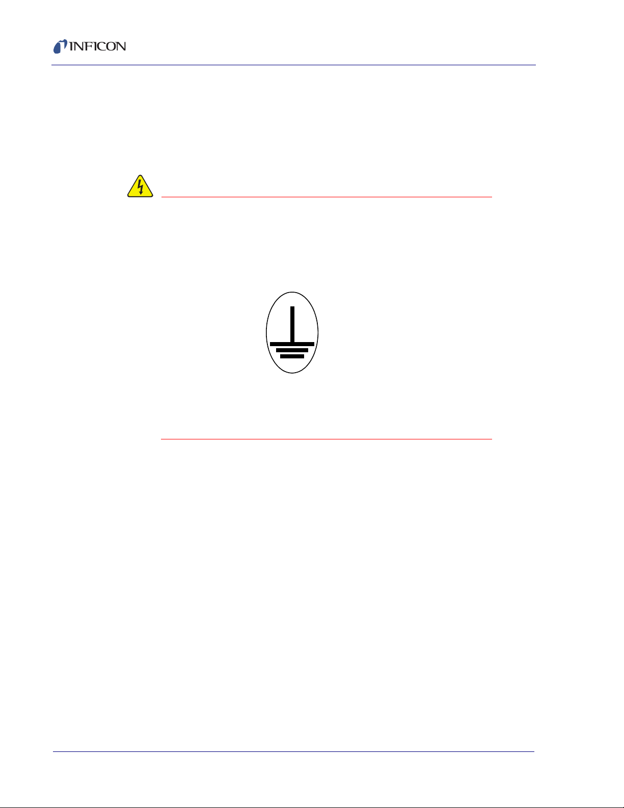
1.2.3 Earth Ground
The Cygnus 2 is connected to earth ground through a sealed three-core
(three-conductor) power cable, which must be plugged into a socket outlet with a
protective earth terminal. Extension cables must always have three conductors
including a protective earth terminal.
Never interrupt the protective earth circuit.
Any interruption of the protective earth circuit inside or
outside the Cygnus 2, or disconnection of the protective
earth terminal is likely to make the Cygnus 2 dangerous.
This symbol indicates where the protective earth ground
is connected inside the Cygnus 2. Never unscrew or
loosen this connection.
IPN 074-545-P1E
1 - 4
Page 23

1.2.4 Main Power Connection
WARNING - Risk Of Electric Shock
This Cygnus 2 has line voltage present on the primary
circuits whenever it is plugged into a main power source.
Never remove the covers from the Cygnus 2 during
normal operation.
There are no operator-serviceable items within the
Cygnus 2.
Removal of the top or bottom covers must be done only
by a technically qualified person.
In order to comply with accepted safety standards, the
Cygnus 2 must be installed into a rack system which
contains a mains switch. This switch must break both
sides of the line when it is open and it must not
disconnect the safety ground.
Cygnus 2 Operating Manual
IPN 074-545-P1E
1 - 5
Page 24

Cygnus 2 Operating Manual
1.3 How To Contact INFICON
Worldwide customer support information is available under Support at
www.inficon.com where you can contact:
a Technical Support Engineer with questions regarding applications for and
programming the Cygnus 2.
a Service Engineer with questions regarding troubleshooting, diagnosing or
repairing a defective Cygnus 2.
Sales and Customer Service, to find the INFICON Sales office nearest to you.
Repair Service, to find the INFICON Service Center nearest to you.
If you are experiencing a problem with your Cygnus 2, please have the following
information readily available:
the serial number and firmware version for your Cygnus 2,
a description of your problem,
an explanation of any corrective action that you may have already attempted,
and the exact wording of any error messages that you may have received.
1.3.1 Returning Your Cygnus 2
Do not return any component of your Cygnus 2 to INFICON without first speaking
with a Customer Support Representative. You must obtain a Return Material
Authorization (RMA) number from the Customer Support Representative.
If you deliver a package to INFICON without an RMA number, your package will be
held and you will be contacted. This will result in delays in servicing your Cygnus 2.
Prior to being given an RMA number, you may be required to complete a
Declaration Of Contamination (DOC) form if your sensor has been exposed to
process materials. DOC forms must be approved by INFICON before an RMA
number is issued. INFICON may require that the sensor be sent to a designated
decontamination facility, not to the factory.
IPN 074-545-P1E
1 - 6
Page 25

1.4 Cygnus 2 Specifications
1.4.1 Measurement
Crystal Frequency . . . . . . . . . . . . . . 6.0 MHz (new crystal) to 4.5 MHz
Internal Precision . . . . . . . . . . . . . . . ±0.0035 Hz over 100 ms sample for
Thickness & Rate Resolution . . . . . . 0.0042 Å (new crystal);
Thickness Accuracy . . . . . . . . . . . . . 0.5% typical, (dependent on process
Frequency Accuracy. . . . . . . . . . . . . ±2 ppm 0-50°C
Measurement Frequency . . . . . . . . . 10 Hz
Measurement Technique . . . . . . . . . ModeLock with Auto-Z
Cygnus 2 Operating Manual
fundamental and anharmonic frequencies
0.0076 Å (crystal @ 4.5 MHz) over
100 ms sample for material density = 1.0,
Z-Ratio = 1.0
conditions, especially sensor location,
material stress, temperature and density)
User Interface. . . . . . . . . . . . . . . . . . LCD and limited membrane keypad. All
parameters accessible through computer
communications. Multiple message areas for
indication of states and detailed indication of
abnormal and stop conditions.
1.4.2 Screens and Hierarchy
a) Navigation . . . . . . . . . . . . . . . . . . Menu driven, four soft keys
b) Structure. . . . . . . . . . . . . . . . . . . . Separate screens dedicated to
1) Operate
2 ) Se ns or In f or ma t io n
3) Sensor Parameters
IPN 074-545-P1E
4) Source Parameters
5) Material Parameters
6) General Parameters
7) Digital I/O Display
8) Logic
9) Maintenance
10) Counter/Timer
11) USB Storage
1 - 7
Page 26

Cygnus 2 Operating Manual
1.4.3 Cygnus 2 Features
1.4.3.1 Recipe Storage & Datalogging
USB Memory Device
1.4.3.2 Sensor Parameters
(Sensor) Shutter Output . . . . . . . . . . 0 to 38
Sensor Type. . . . . . . . . . . . . . . . . . . Single, XtalTwo, XtalSix, Xtal12, Generic
(Sensor) Switch Output . . . . . . . . . . 0 to 38
Auto-Z . . . . . . . . . . . . . . . . . . . . . . . Yes/No
# of Positions (for Generic Sensor type)1 to 12
# of Pulses (for Generic Sensor type)1 to 10
Pulse On (Time for Generic Sensor type)0.1 to 9.9 s
Pulse Off (Time for Generic Sensor type)0.1 to 9.9 s
Recorder Output. . . . . . . . . . . . . . . . 0 to 12
Recorder Function . . . . . . . . . . . . . . Rate, Thickness, RateDeviation
Recorder Range. . . . . . . . . . . . . . . . 0 to 99999
1.4.3.3 Source Parameters
Up to 6 Sources may be controlled at the same time
DAC Output . . . . . . . . . . . . . . . . . . . 0 to 12
(Source) Shutter Output . . . . . . . . . . 0 to 38
Crucible Selection . . . . . . . . . . . . . . Turret is indexed to selected position on a
Number of Crucibles. . . . . . . . . . 1, 4, 8, 16, 32 or 64
Crucible Output . . . . . . . . . . . . . 0 to 38
Turret Feedback. . . . . . . . . . . . . Yes / No
Turret Input. . . . . . . . . . . . . . . . . 0 to 28
Turret Delay . . . . . . . . . . . . . . . . 2 to 180 s (Time-out period with feedback,
Start. Turret feedback is checked whenever a
Source is started. Range is from 1 to number
of crucibles.
IPN 074-545-P1E
delay time without feedback)
1 - 8
Page 27

1.4.3.4 Material Parameters
6 Materials can be specified and given unique names (15 character max.).
Density . . . . . . . . . . . . . . . . . . . . . . . 0.100 to 99.999 gm/cc
Z-ratio . . . . . . . . . . . . . . . . . . . . . . . . 0.100 to 15.000
Master Tooling . . . . . . . . . . . . . . . . . 1.0 to 999.9%
Control Loop types . . . . . . . . . . . . . . Non-PID, PI, PID
Process Gain . . . . . . . . . . . . . . . . . . 0.01 to 999.99 Å/s/%Power
Time Constant . . . . . . . . . . . . . . . . . 0.010 to 9999.99 s
Dead Time . . . . . . . . . . . . . . . . . . . . 0.010 to 9999.99 s
Maximum Source Power . . . . . . . . . 0.01 to 99.99%
Minimum Source Power . . . . . . . . . . 0.00 to 99.98%
Maximum Power Option . . . . . . . . . . Continue, Post-Dep(osition), Stop All, Stop
Cygnus 2 Operating Manual
Mat(erial)—can be selected for each
Material individually
Power Ramps. . . . . . . . . . . . . . . . . . 3 per Material
Power Level . . . . . . . . . . . . . . . . 0.00 to 99.99%
Rise Time . . . . . . . . . . . . . . . . . . 00:00 to 99:59 min:s
Soak Time. . . . . . . . . . . . . . . . . . 00:00 to 99:59 min:s
Auto Soak 2 . . . . . . . . . . . . . . . . . . . Yes / No
Deposit After Pre-Deposit. . . . . . . . . Yes / No
Yes = go to Deposit
No = go to Non-Deposit Rate Control
(Control) Delay Option . . . . . . . . . . . None, Shutter, Control, Both
Control Delay Time. . . . . . . . . . . . . . 00:00 to 99:59 min:s
IPN 074-545-P1E
Shutter Delay Accur(acy) . . . . . . . . . 1 to 99%
Feed Power . . . . . . . . . . . . . . . . . . . 0.00 to 99.99%
Feed Ramp Time . . . . . . . . . . . . . . . 00:00 to 99:59 min:s
Feed Time . . . . . . . . . . . . . . . . . . . . 00:00 to 99:59 min:s
Idle Ramp . . . . . . . . . . . . . . . . . . . . . 1 per Source
Idle Power. . . . . . . . . . . . . . . . . . 0.00 to 99.99%
Idle Ramp Time . . . . . . . . . . . . . 00:00 to 99:59 min:s
Rate . . . . . . . . . . . . . . . . . . . . . . . . . 0.000 to 999.9 Å/s
1 - 9
Page 28

Cygnus 2 Operating Manual
Time Limit (in Deposit) . . . . . . . . . . . 00:00 to 99:59 min:s
Rate Filter Time . . . . . . . . . . . . . . . . 0.1, 0.4, 1.0, 4.0, or 10.0, 20.0, 30.0 s
Time Power Averaging Time . . . . . . 0 to 30 minutes
Ion Assist Deposit . . . . . . . . . . . . . . Yes/No
On Final Thickness . . . . . . . . . . . . . Continue, Post-Dep(osit),
NonDep(osit)Cont(rol)
New Rate while in Deposit . . . . . . . . 2 Rate Ramps per Material
New Rate 1 or 2 . . . . . . . . . . . . . 0.000 to 999.9 Å/s
Start Ramp 1 or 2 . . . . . . . . . . . . 0.000 to 999.9 kÅ
Ramp Time 1 or 2. . . . . . . . . . . . 00:00 to 99:59 min:s
RateWatcher® . . . . . . . . . . . . . . . . Sample and Hold Feature
(RateWatcher) Option. . . . . . . . . Yes/No
(RateWatcher) Time . . . . . . . . . . 00:00 to 99:59 min:s
(RateWatcher) Accuracy . . . . . . 1 to 99%
(Sensor) Failure Action . . . . . . . . . . PostD(e)p(osit), Stop All, Stop Matl,
TimeP(o)w(er)
CrystalTwo Tooling . . . . . . . . . . . . . . 1.0 to 999.9%
CrystalSix (XtalSix) and Crystal12 (Xtal12) sensor selections to specify a subset of
available crystal positions:
Xtal Position First . . . . . . . . . . . . 0 to 6 (XtalSix) or 12 (Xtal12)
Xtal Position Last . . . . . . . . . . . . 0 to 6 (XtalSix) or 12 (Xtal12)
(Crystal) Quality Percent . . . . . . . . . 0 to 99%
(Crystal) Quality Counts . . . . . . . . . . 0 to 99
(Crystal) Stability Single . . . . . . . . . . 0 to 9999 Hz
(Crystal) Stability Total . . . . . . . . . . . 0 to 9999 Hz
Recorder Output. . . . . . . . . . . . . . . . 0 to 12
Recorder Function . . . . . . . . . . . . . . Rate, Thick(ness), RateDev(iation), Power
Recorder Range. . . . . . . . . . . . . . . . 0 to 99999
Final Thick(ness) . . . . . . . . . . . . . . . 0.000 to 999.99 kÅ
IPN 074-545-P1E
1 - 10
Thick(ness) Limit . . . . . . . . . . . . . . . 0.000 to 999.99 kÅ
Cruc(ible) . . . . . . . . . . . . . . . . . . . . . 1 to 64
Page 29

1.4.3.5 General Global Parameters
Date Format . . . . . . . . . . . . . . . . . . . DDMMYYYY or MMDDYYYY
LCD Dimmer Time . . . . . . . . . . . . . . 0 for Always On or # of Minutes till Off
Graph Scale . . . . . . . . . . . . . . . . . . . Power, +/-10 Å/s, +/-20 Å/s
Graph Scan Rate . . . . . . . . . . . . . . . Auto, Slow, Medium, Fast
Test . . . . . . . . . . . . . . . . . . . . . . . . . On / Off
Advanced Test . . . . . . . . . . . . . . . . . On / Off
Time Compressed . . . . . . . . . . . . . . Yes / No
Audio Feedback . . . . . . . . . . . . . . . . Yes / No
RS232 Baud Rate . . . . . . . . . . . . . . 9600, 19200, 38400, 57600, 115200
RS232 Protocol . . . . . . . . . . . . . . . . Standard, D(ata)log Page, D(ata)log Comma
DataLog XTAL History . . . . . . . . . . . Yes / No
USB Datalog Format . . . . . . . . . . . . Log Off (No datalogging), Page, Comma
Cygnus 2 Operating Manual
0 to 99 minutes
Thickness Eq(uation) 1. . . . . . . . . . . Up to 6 Source numbers can be specified,
each Source number can be used only once
in the equation.
Thickness Eq(uation) 2. . . . . . . . . . . Up to 6 Source numbers can be specified,
each Source number can be used only once
in the equation.
Thickness Eq(uation) 3. . . . . . . . . . . Up to 6 Source numbers can be specified,
each Source number can be used only once
in the equation.
DAC 1 to 12 Scale . . . . . . . . . . . . . . 0.1 to 10.0
DAC 1 to 12 Polarity. . . . . . . . . . . . . Positive / Negative
IPN 074-545-P1E
1 - 11
Page 30

1.4.4 ‘Display
Type/Color/Size . . . . . . . . . . . . . . . . LCD/Color/TFT/7 inch diagonal
Dimming Feature . . . . . . . . . . . . . . . Always Full on or Full on when in use.
Format . . . . . . . . . . . . . . . . . . . . . . . WVGA
Resolution . . . . . . . . . . . . . . . . . . . . 800 W x 480 H
Backlighting . . . . . . . . . . . . . . . . . . . LED
Thickness Display Range. . . . . . . . . 0.000 to +/-9999 kÅ
Thickness Display Resolution . . . . . 1 Å for 0.000 to +/-9.999 kÅ,
. . . . . . . . . . . . . . . . . . . . . . . . . . . . . 1 kÅ for +/-1000 to +/-9999 kÅ
Rate Display Range . . . . . . . . . . . . . 0.000 to +/-999.9 Å/s
Cygnus 2 Operating Manual
Full off when no process running and no key
interaction for dimming time
10 Å for +/-10.00 to +/-99.99 kÅ
100Å for +/-100.0 to +/-999.9 kÅ
Rate Display Resolution. . . . . . . . . . 0.001 Å/s for 0.000 to +/-9.999 Å/s,
. . . . . . . . . . . . . . . . . . . . . . . . . . . . . 0.01 Å/s for +/-10.00 to +/-99.99 Å/s
0.1 Å/s for +/-100.0 to +/-999.9 Å/s
Power Display Range. . . . . . . . . . . . 0.00 to 99.99%
Graphic Display Functions . . . . . . . . Rate Deviation at ±10 or ±20 Å/s or
Power at 0 to 100%
Display Data Update Rate . . . . . . . . 1 Hz
IPN 074-545-P1E
1 - 12
Page 31

1.4.5 DAC Outputs
Quantity and Type . . . . . . . . . . . . . . 6 with BNC, 6 optional with 15 pin miniature
Configuration . . . . . . . . . . . . . . . . . . User programmable for recorder
Function and Ranges . . . . . . . . . . . . Power, Rate, Rate Deviation, Thickness
Current rating . . . . . . . . . . . . . . . . . . 20 mA per channel
Resolution . . . . . . . . . . . . . . . . . . . . 15 bits over full range (10 V)
Update Rate . . . . . . . . . . . . . . . . . . . 10 Hz, maximum, (dependent on source
Recorder Output Functions . . . . . . . Rate, Thickness, Rate Deviation, or Source
Cygnus 2 Operating Manual
D-sub providing analog outputs for Rate and
Thickness.
or Source control.
Full scale voltage value fully selectable up to
+ or - 10 V relative to 0 V at 0 output
characteristics).
Power.
Recorder Output Ranges
Rate . . . . . . . . . . . . . . . . . . . . . . 0 to up to 99999 Å/s programmable
Thickness . . . . . . . . . . . . . . . . . . 0 to up to 99999 Å programmable, [Function
modulo (Thickness Range, Thickness)output
is "saw-tooth" like with increasing thickness.]
Rate Deviation . . . . . . . . . . . . . . Desired rate ±50 Å/s
Accuracy. . . . . . . . . . . . . . . . . . . . . . ±1%
IPN 074-545-P1E
1 - 13
Page 32

Cygnus 2 Operating Manual
1.4.6 Logic Processing
Type . . . . . . . . . . . . . . . . . . . . . . . . . If/Then statements
Logical Functions . . . . . . . . . . . . . . . And; Or; Not; Parentheses; ON
Depth . . . . . . . . . . . . . . . . . . . . . . . . 5 "If" conditions and 5 "Then" results/actions
# of Statements . . . . . . . . . . . . . . . . 100 If/Then
Selectable events. . . . . . . . . . . . . . . Deposition monitor events, states, external
Hierarchy . . . . . . . . . . . . . . . . . . . . . Statements evaluated in numerical order at
Partitioning . . . . . . . . . . . . . . . . . . . . None
Initialization . . . . . . . . . . . . . . . . . . . All outputs transition to their normal states as
per statement
inputs, relays, timers, and counters.
10 Hz any time the Cygnus 2 is on.
early as possible during power-on
initialization sequence.
1.4.7 Relays / Inputs
Relays . . . . . . . . . . . . . . . . . . . . . . . SPST 2.5 A relays rated @ 30 V (dc) or
Relay Ratings. . . . . . . . . . . . . . . . . . 100 VA inductive; 2.5 A maximum.
# of TTL Compatible Outputs . . . . . . 14 with optional I/O card. Internally pulled up
Inputs (TTL Compatible). . . . . . . . . . (14 standard, 14 additional optional)
Input Levels
maximum high . . . . . . . . . . . . . . 24 V
minimum high. . . . . . . . . . . . . . . 2.5 V
30 V (ac) RMS or 42 V (peak) maximum;
(8 standard, up to 16 optional with 2
additional I/O cards); D sub connector; relays
are normally open in the power off state, but
may be programmed to normally open or
normally closed during operation.
to 5 V (dc). May be pulled up externally to
24 V (dc) through 2.4 k resistor.
minimum high level 0.5 mA load @3.75 V
maximum low level 10 mA load @1.1 V
IPN 074-545-P1E
1 - 14
maximum low . . . . . . . . . . . . . . . 1.1 V
Scan/Update Rate . . . . . . . . . . . . . . 10 Hz
Input/Output Name. . . . . . . . . . . . . . Those that are Non-Hardware reserved may
be named. (15 character max.)
Page 33

1.4.8 Remote Communications
RS232C Serial Port . . . . . . . . . . . . . Standard; INFICON binary protocol
Baud Rates. . . . . . . . . . . . . . . . . . . . 115,200, 57,600, 38,400, 19,200, 9,600
Ethernet . . . . . . . . . . . . . . . . . . . . . . Optional, Programmable IP Address and
USB port. . . . . . . . . . . . . . . . . . . . . . Print screen bitmap (.bmp) files, Datalogging
1.4.9 Accessories
Connector Kit . . . . . . . . . . . . . . . . . . Connectors for inputs and relays
Operating Manual. . . . . . . . . . . . . . . 074-5000-G1 CD-ROM
1.4.10 Power
Power . . . . . . . . . . . . . . . . . . . . . . . . 100-230 V (ac) +/-15% V (ac); 50/60 Hz
Cygnus 2 Operating Manual
Net Mask
file, Configuration file store/retrieve
+/-3Hz Maximum apparent power 150 VA
Fuse . . . . . . . . . . . . . . . . . . . . . . . . . use 250 V 4 Amp, 5 x 20, Slow Blow
1.4.11 Operating Environment
Usage . . . . . . . . . . . . . . . . . . . . . . . . Indoor only
Temperature . . . . . . . . . . . . . . . . . . . 0 to 50°C (32-122°F)
Humidity . . . . . . . . . . . . . . . . . . . . . . Up to 85% RH, non-condensing
Altitude . . . . . . . . . . . . . . . . . . . . . . . Up to 2000 meters
Installation (Overvoltage) . . . . . . . . . Category II per IEC 60664
Pollution Degree. . . . . . . . . . . . . . . . 2 per EN 61010
IPN 074-545-P1E
1.4.12 Storage Temperature
Storage Temperature . . . . . . . . . . . . -10 to 60°C (14 to 140°F)
1.4.13 Warm Up Period
Warm Up Period. . . . . . . . . . . . . . . . None required;
For maximum stability allow 5 minutes.
1 - 15
Page 34

Cygnus 2 Operating Manual
1.4.14 Size
Not including mounts or user connectors
5.25 in. H x 17.625 in. W x 13 in. D
(133.4 mm H x 447.7 mm W x 330 mm D)
Including mounts, but no user connectors
5.25 in. H x 19 in. W x 13 in. D
(133.4 mm H x 482.6 mm W x 330 mm D)
1.4.15 Installation Clearance Requirements
1.4.15.1 Connector Clearances:
Front. . . . . . . . . . . . . . . . . . . . . . . . . 1.0 in. (25 mm) minimum without USB, 2.5 in
(64 mm) minimum dependent on size of USB
storage device
Rear . . . . . . . . . . . . . . . . . . . . . . . . . 4.0 in. (100 mm) minimum
1.4.15.2 Cooling Clearances:
Rear . . . . . . . . . . . . . . . . . . . . . . . . . 4.0 in. (100 mm) minimum
Sides . . . . . . . . . . . . . . . . . . . . . . . . 1/4 in. (7 mm) minimum
1.4.16 Weight
With all options. . . . . . . . . . . . . . . . . 13 lb. (5.9 kg)
1.4.17 Cleaning
Use a mild, nonabrasive cleaner or detergent taking care to prevent cleaner from
entering the Cygnus 2.
IPN 074-545-P1E
1 - 16
Page 35

1.5 Unpacking and Inspection
1 If the Cygnus 2 has not been removed from its shipping container, do so now.
2 Carefully examine the Cygnus 2 for damage that may have occurred during
shipping. This is especially important if you notice obvious rough handling on
the outside of the container. Immediately report any damage to the carrier and
to INFICON.
3 Do not discard the packing materials until you have taken inventory and have
at least performed a power on verification.
4 Take an inventory of your order by referring to your order invoice and the
information contained in section 1.6 on page 1-17.
5 To perform a power-on verification, see section 1.7 on page 1-19.
6 For additional information or technical assistance, contact INFICON, refer to
section 1.3, How To Contact INFICON, on page 1-6.
1.6 Parts and Options Overview
Cygnus 2 Operating Manual
1.6.1 Base Configurations
Cygnus 2 Control Unit . . . . . . . . . . . 781-500-G11 North America,
781-500-G12 Europe
Ship Kit . . . . . . . . . . . . . . . . . . . . . . . 781-020-G1 North America,
781-020-G2 Europe
Operating Manual on CD ROM . . . . 074-545 on 074-5000-G1 CD ROM included
in Ship Kit
I/O Relay . . . . . . . . . . . . . . . . . . . . . Contains Input/Relay Interface Connectors
(8 relay outputs, 14 TTL inputs). Included in
Ship Kit.
IPN 074-545-P1E
1.6.2 Pre-installed Options or Spares
Additional Sensor Module . . . . . . . . 781-132-G1 (up to 2 extra)
The following contain board and interface connector
I/O Relay Card . . . . . . . . . . . . . . . . . 781-502-G1
(8 relay outputs, 14 TTL inputs)
781-503-G1
(8 relay outputs, 14 TTL outputs)
DAC Option Board and Kit . . . . . . . . 781-504-G1
Ethernet . . . . . . . . . . . . . . . . . . . . . . 781-102-G2
1 - 17
Page 36

Cygnus 2 Operating Manual
1.6.3 Optional Accessories
Pneumatic Shutter
Actuator Control Valve . . . . . . . . . . . 750-420-G1
Sensor Emulator Kit . . . . . . . . . . . . . 760-601-G2
Handheld Controller . . . . . . . . . . . . 755-262-G1
Function:Power Increase/Decrease/Stop/Switch Crystal
1.6.4 Oscillator Packages
Cygnus 2 Oscillator, 15 ft. and 6 in. cable pkg.781-611-G15
Cygnus 2 Oscillator, 30 ft. and 6 in. cable pkg.781-611-G30
Cygnus 2 Oscillator, 50 ft. and 6 in. cable pkg.781-611-G50
Cygnus 2 Oscillator, 100 ft. and 6 in. cable pkg.781-611-G100
4 Meter Oscillator, 15 ft. and 6 in. cable pkg. . . . . . 781-612-G15
4 Meter Oscillator, 30 ft. and 6 in. cable pkg. . . . . . 781-612-G30
4 Meter Oscillator, 50 ft. and 6 in. cable pkg. . . . . . 781-612-G50
4 Meter Oscillator, 100 ft. and 6 in. cable pkg. . . . . 781-612-G100
4 Meter Oscillator, 15 ft. and 20 in. cable pkg. . . . . 781-613-G15
4 Meter Oscillator, 20 ft. and 20 in. cable pkg. . . . . 781-613-G20
4 Meter Oscillator, 50 ft. and 20 in. cable pkg. . . . . 781-613-G50
4 Meter Oscillator, 100 ft. and 20 in. cable pkg. . . . 781-613-G100
1.6.5 Sensors
Contact INFICON for a complete listing of sensors.
1.6.6 Replacement Cables
Oscillator to vacuum. . . . . . . . . . . . . 755-257-G6
feedthrough cable, 6 in
Cygnus 2 Unit to Oscillator Cable 15 ft. 600-1261-P15
Cygnus 2 Unit to Oscillator Cable, 30 ft. 600-1261-P30
Cygnus 2 Unit to Oscillator Cable, 50 ft. 600-1261-P50
Cygnus 2 Unit to Oscillator Cable, 100 ft. 600-1261-P100
IPN 074-545-P1E
1 - 18
Page 37

1.7 Initial Power-On Verification
WARNING - Risk Of Electric Shock
WARNING - Risk Of Electric Shock
A preliminary functional check of the Cygnus 2 can be made before formal
installation. It is not necessary to have sensors, source controls, inputs or relays
connected to do this. For more complete installation information, see Chapter 2,
Installation and Interfaces and Chapter 10, Maintenance and Calibration
Procedures.
There are no user-serviceable components within the
Cygnus 2 case.
Dangerous voltages may be present whenever the power
cord or external input/relay connectors are present.
Refer all maintenance to qualified personnel.
Cygnus 2 Operating Manual
Never interrupt the protective earth circuit.
Any interruption of the protective earth circuit inside or
outside the Cygnus 2, or disconnection of the protective
earth terminal is likely to make the Cygnus 2 dangerous.
IPN 074-545-P1E
This symbol indicates where the protective earth ground
is connected inside the Cygnus 2. Never unscrew or
loosen this connection.
1 - 19
Page 38

Cygnus 2 Operating Manual
1 Confirm that AC line voltage is supplied and proper for the Cygnus 2.
2 Confirm that the back panel (main) AC switch is in the ON position.
3 Press the ON/STBY button on the front panel. A green pilot light should be
illuminated next to the power switch.
4 The fan at the back of the Cygnus 2 should be exhausting air.
5 After the initial temporary boot-up screen which can be viewed in Maintenance
Sys Status, the LCD monitor will display an image similar to the one shown in
Figure 1-1 or Figure 1-2.
Figure 1-1 Operate screen show graph
Figure 1-2 Operate screen show all materials
IPN 074-545-P1E
1 - 20
Page 39

2.1 Location Guidelines
CAUTION
Before permanently installing the Cygnus 2, read this entire chapter on installation
and interfaces and follow its recommendations as closely as possible. INFICON
has taken numerous steps to ensure its equipment will operate in a variety of harsh
situations. Failure to adhere to these simple practices may adversely affect the
performance and longevity of the Cygnus 2.
2.1.1 Sensor Types
The choice of sensor type must be dictated by the process, the deposition material
and the physical characteristics of the process chamber. General guidelines for
each sensor type produced by INFICON are outlined in the Sensor Data Sheets on
the www.inficon.com website. For specific recommendations, consult your
INFICON representative.
Cygnus 2 Operating Manual
Chapter 2
Installation and Interfaces
The performance of this Cygnus 2 depends on the careful
installation of the chosen transducer. Improper
installation will cause problems with deposition
repeatability, crystal life and rate stability.
2.1.2 Sensor Installation
Figure 2-1 shows a typical installation of an INFICON water cooled crystal sensor
IPN 074-545-P1E
in the vacuum process chamber. Use the illustration and the following guidelines to
install your sensors for optimum performance and convenience.
2 - 1
Page 40

Cygnus 2 Operating Manual
Mounting Bracket
Coax Cable
(Routed with
Water Tubes)
Or,
Customer Supplied
Cajon Coupling
Brazing
Adapters
Water In
Water Out
XIU (Oscillator)
Instrument Chassis
Source
Source
Shutter
Pneumatic
Actuator
To
Source Controller
Source to Sensor
10" Minimum
Sensor
Shutter
Air, 80 PSI, 110 PSI Max.
To
Sensor
Shutter
IPN 750-420-G1
Shutter
Solenoid
Assembly
Figure 2-1 Typical installation
IPN 074-545-P1E
2 - 2
Page 41

Cygnus 2 Operating Manual
Correct
Incorrect
Correct
Incorrect
Incorrect
Obstruction
Source
Generally, install the sensor as far as possible from the evaporation source (a
minimum of 10 in. (25.4 cm) is recommended) while still being in a position to
accumulate thickness at a rate proportional to accumulation on the substrate.
Figure 2-2 shows proper and improper methods of installing sensors.
Figure 2-2 Sensor installation guidelines
IPN 074-545-P1E
To guard against spattering, use a source shutter or crystal shutter to shield the
crystal during the initial soak periods. If the crystal is hit with even a minute particle
of molten material, it may be damaged and stop oscillating. Even in cases when it
does not completely stop oscillating, it may become unstable. Follow these
precautions:
Mount the sensor to something rigid and fixed in the chamber. Do not rely on
the water tubes to provide support.
Plan the installation to insure there are no obstructions blocking the path
between the sensor and the source. Be certain to consider rotating or moving
fixtures.
Install sensors so their central axis (an imaginary line drawn normal to the
center of the crystal face) is aimed directly at the virtual source being
monitored.
Be sure there is easy access for the exchange of crystals.
For systems employing simultaneous source evaporation (co-deposition), try to
locate the sensors so the evaporant from each source is flowing to only one
sensor. It is not generally possible to do this without special shielding or
optional “material directors.”
2 - 3
Page 42

Cygnus 2 Operating Manual
CAUTION
2.1.3 Cygnus 2 Installation
The Cygnus 2 is designed to be rack mounted. It may be also used on a table. The
Cygnus 2 is forced-air cooled, with the air flow exiting the rear of the Cygnus 2 for
clean room convenience.
It is generally advisable to centrally locate the Cygnus 2, minimizing the length of
external cabling. The cable from the instrument to the XIU is typically fifteen feet.
Thirty, fifty and one hundred foot cables are available.
2.2 Avoiding Electrical Interference
Careful consideration of simple electrical guidelines during installation will avoid
many problems caused by electrical noise.
To maintain the required shielding and internal grounding and ensure safe and
proper operation, the Cygnus 2 must be operated with all enclosure covers,
sub-panels and braces in place and fully secured with the screws and fasteners
provided.
When using the Cygnus 2 with an RF sputtering system,
the cable between the Cygnus 2 and oscillator should be
kept as far away from the RF transmission cable as
possible. Interference from the RF transmission cable
may cause an erroneous crystal fail.
2.2.1 Verifying/Establishing Earth Ground
If a ground must be established, the following procedure is recommended:
Where soil conditions allow, drive two ten foot copper clad steel rods into the
ground six feet apart. Pour a copper sulfate or a salt solution around each rod
to improve the ground’s conduction. A near zero resistance measurement
indicates earth ground is achieved.
Keep connections to this grounding network as short as possible.
IPN 074-545-P1E
2 - 4
Page 43
2.2.2 Connections to Earth Ground
WARNING - Risk Of Electric Shock
CAUTION
There are two required earth ground connections:
The earth ground connection on the Cygnus 2 is a threaded stud with a hex nut.
Connect a ring terminal to the ground strap, thus allowing a good connection
and easy removal and installation. This connection must be made at
installation. For best protection against high frequency noise, the
length-to-width ratio of the earth conductor should not exceed 5:1
2-3 for the suggested method of grounding.
This Cygnus 2 is also connected to earth ground via a sealed three-core power
cable, which must be plugged into a socket outlet with a protective earth ground
terminal. Extension cables must always have three conductors including a
protective earth ground conductor.
Never interrupt the protective earth ground intentionally.
Any interruption of the protective earth ground
connection inside or outside the Cygnus 2 or
disconnection of the protective earth ground terminal is
likely to make the Cygnus 2 dangerous.
Cygnus 2 Operating Manual
. See Figure
This symbol indicates where the protective earth ground
is connected inside the Cygnus 2. Never unscrew or
loosen this connection.
IPN 074-545-P1E
An external earth ground connection is required to
ensure proper operation, especially in electrically noisy
environments.
When used with RF powered sputtering systems, the grounding method may have
to be modified to the specific situation. An informative article on the subject of
Grounding and RFI Prevention was published by H.D. Alcaide, in “Solid State
Technology”, p.117, April, 1982.
2 - 5
Page 44
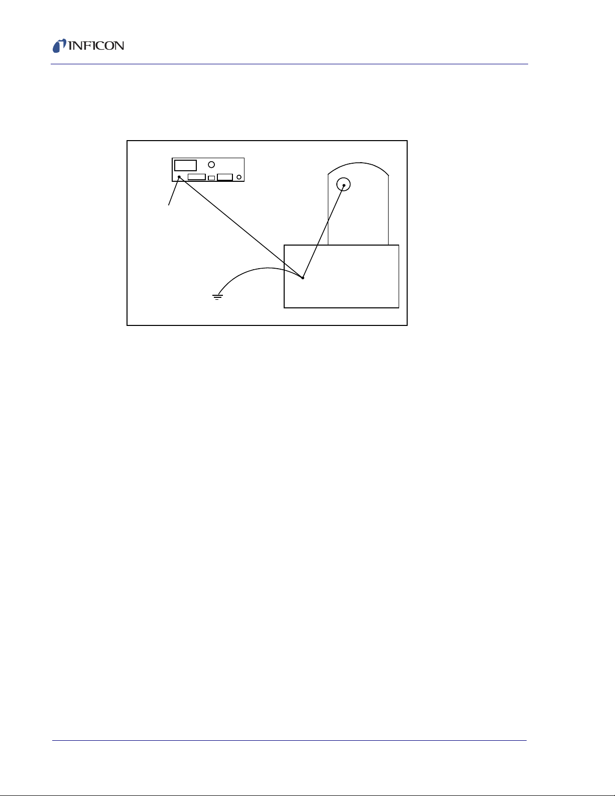
Cygnus 2 Operating Manual
Back Panel
Ground
Stud
Earth
Ground
Transducer
Feedthrough
Vacuum System
In many cases, a braided ground strap is sufficient. However, there are cases when
a solid copper strap (0.030 in. thick x 1 in. wide) is required because of its lower RF
impedance.
Figure 2-3 System grounding diagram
2.2.3 Minimizing Noise Pickup From External Cabling
When a Cygnus 2 is fully integrated into a deposition system, there can be many
wire connections, each a potential path for electrical noise to reach the inside of the
Cygnus 2. The likelihood of these wires causing a problem can be greatly
diminished by adhering to the following guidelines.
Use shielded coax cable or twisted pairs for all connections.
Minimize cable lengths.
Avoid routing cables near areas that have the potential to generate high levels
of interference. For example, large power supplies such as those used for
electron beam guns or sputtering sources can be a source of large, rapidly
changing electromagnetic fields. Placing cables as little as one foot away from
these problem areas can significantly reduce noise pickup.
Be sure that a good ground system and straps are in place per the
recommendations in section 2.2.2 on page 2-5.
Ensure that all Cygnus 2 covers and option panels are in place and tightly
secured with the provided fasteners.
NOTE: Always use shielded cables when making connections to the Cygnus 2
rear panel to minimize electrical noise pickup.
IPN 074-545-P1E
2 - 6
Page 45

2.3 Connecting the Controller
WARNING - Risk Of Electric Shock
The operation of the Cygnus 2 depends on the proper connection of power and
signal interfaces to owner equipment and sources.
This Cygnus 2 has line voltage present on the primary
circuits whenever it is plugged into a mains power
source.
Never remove the cover from the Cygnus 2 during normal
operation.
There are no operator serviceable items within the
Cygnus 2.
Removal of the cover must be done only by a technically
qualified person.
Cygnus 2 Operating Manual
In order to comply with accepted safety standards, the
Cygnus 2 must be installed into a rack or system which
contains a mains switch. This switch must break both
sides of the line when it is open and it must not interfere
with the safety earth ground.
The Cygnus 2 is initially powered by AC line current. The line voltage provided in
your facility must be within the voltage range shown in section 1.4.10, Power, on
page 1-15.
2.3.1 Routing XIU Cables
IPN 074-545-P1E
The signals traveling on this cable are both analog and digital. It is suggested that
it not be routed near areas with high levels of electromagnetic interference, even if
its length must be somewhat increased.
2.3.2 Interface Cable Fabrication and Pin-Out
It is necessary to fabricate several cables in order to interface the Cygnus 2 to the
deposition system. Refer to section 2.2.3, Minimizing Noise Pickup From External
Cabling, on page 2-6.
2 - 7
Page 46

Cygnus 2 Operating Manual
2.3.2.1 Source Control Connection
Six Digital-to-Analog (DAC) outputs are provided as standard equipment with the
Cygnus 2. These standard 6 DAC channels with BNC connectors and six optional
DAC outputs on a 15 pin sub-D connector may be programmed for Source control
or chart recorder functions as desired.
2.3.2.2 Crucible Indexer Connections
Example: 4 pocket crucible using outputs 6 and 7
Number of crucibles = 4
Crucible output = 6
For this example, wiring to the controller is based on Table 2-1. Only relays 6 and
7 are needed to encode the four possible positions.
Table 2-1 Wiring to the controller
Crucible
Position Contact Status
Relay #6 Relay #7
1 Open Open
2 Closed Open
3OpenClosed
4 Closed Closed
2.3.2.3 DAC Option Kit
An optional Digital-to-Analog Converter (DAC) card can be installed into the
Cygnus 2. This card provides six additional DAC outputs, numbered 7 through 12,
for Thickness and/or Rate as determined by the DAC Output Option parameters.
The pin assignments for DAC outputs 7 through 12 are shown in Table 2-2.
Table 2-2 Optional DAC pin assignments
Output
Number
7 1, 6 (GND)
8 2, 7 (GND)
9 3, 8 (GND)
10 4, 9 (GND)
Pin
IPN 074-545-P1E
2 - 8
11 5, 10 (GND)
12 11, 12 (GND)
A mating connector is included
with the DAC option.
Page 47

2.3.2.4 I/O Expansion Options
WARNING - Risk Of Electric Shock
One I/O Relay module is included as standard equipment with the Cygnus 2 and is
used to interface with other machinery of the vacuum system. It can control
components such as heaters, rotators or shutters through its 8 relays. It can
respond to external instructions through its 14 isolated input lines. Standard
equipment provides 8 relays and 14 input lines. Optionally, this can be expanded
to 24 relays, 28 TTL inputs, and 14 open collector type outputs with the addition of
another Relay I/O module and a TTL Relay module having 8 relays and 14 TTL
open collector outputs.
The modules provide separate connectors for outputs and input lines. A 25-pin
D-sub, male connector is used for the eight relays. A 15-pin D-sub, male connector
is used for the input lines. Mating connectors are provided. Refer to Figure 3-2 on
page 3-3 for connector locations and Table 2-3 on page 2-10 for connector pin
assignment. Relay connections are rated at 30 V (dc) or 30 V (ac) RMS or
42 V (peak) maximum; 2.5 A maximum.
Inputs are activated by pulling the specific input terminal to ground (<0.8 V) through
a contact closure to common (GND) or with TTL/CMOS Logic having current sink
capability of 2 mA (1 low power TTL load).
Cygnus 2 Operating Manual
The relay, relay circuit, and associated pins in the I/O
connector(s) have a maximum voltage rating of 30 V (dc)
or 30 V (ac) RMS or 42 V (peak). The maximum current
rating per connector pin or relay contact is 2.5 Amps.
IPN 074-545-P1E
2 - 9
Page 48

Cygnus 2 Operating Manual
Table 2-3 Input/Relay pin connections
I/O Board #1 I/O Board #2
Relay # Pins TTL
Input #
17, 6 1 15 97, 6 1515
2 9, 8 2 14 10 9, 8 16 14
3 11, 10 3 13 11 11, 10 17 13
4 13, 12 4 12 12 13, 12 18 12
5 5, 4 5 11 13 5, 4 19 11
6 3, 2 6 10 14 3, 2 20 10
7 1, 14 7 9 15 1, 14 21 9
8 15, 16 8 8 16 15, 16 22 8
97 237
10 6 24 6
11 5 25 5
12 4 26 4
13 3 27 3
14 2 28 2
GND1 GND1
Pin Relay # Pins TTL
Input #
Pin
I/O Board #3
Relay # Pins TTL
Output #
17 7, 6 25 9
18 9, 8 26 10
19 11, 10 27 11
20 13, 12 28 12
21 5, 4 29 13
22 3, 2 30 14
23 1, 14 31 15
24 15, 16 32 1
33 2
34 3
35 4
36 5
37 6
38 7
GND 8
Pin
IPN 074-545-P1E
2 - 10
Page 49

2.3.2.5 RS-232C Communications
RS-232C serial communications is included in the Cygnus 2 as standard
equipment. It can be used to remotely control or monitor the Cygnus 2. An industry
standard 9-pin D-Sub connector is required for the host computer side connection.
Depending on the computer source, all connections may not be necessary. The
length of the cable is limited to fifty feet according to published standards. The
Cygnus 2 interface operates as DCE (Data Communication Equipment). Pin
assignments are for the Cygnus 2 connector.
Table 2-4 RS-232C pin connections
Signal Name Pin EIA Name
TX Transmit Data 2 BA
RX Receive Data 3 BB
SG Signal Ground 5 AB
GND Shield Ground 1
Cygnus 2 Operating Manual
IPN 074-545-P1E
2 - 11
Page 50

Cygnus 2 Operating Manual
CAUTION
2.3.2.6 Isolated +24 V (dc) Supply
An isolated +24 V (dc) power supply is available on a 9-pin D-Sub connector on the
Cygnus 2 back panel. This supply is rated for 1.75 Amps maximum.
The pin assignments for this connector are shown in Table 2-5.
Table 2-5 +24 V (dc) pin connections
Pin Function
1 Return
2 Return
3 Return
4 Not Connected
5 Not Connected
6+24 Volts
7+24 Volts
8+24 Volts
9 Not Connected
Both the isolated 24 V (dc) supply and the RS-232C
remote communications port use a 9-pin D-sub
connector. Care must be taken not to inadvertently
connect the RS-232C remote communications cable to
the 24 V (dc) supply connector. Also, care must be taken
not to inadvertently connect the 24 V (dc) supply cable to
the RS-232C remote communications connector.
IPN 074-545-P1E
2 - 12
Page 51

3.1 Front Panel Controls
1234
5
67891011
5
Operational controls for the Cygnus 2 are located on the front panel, see Figure
3-1.
Figure 3-1 Cygnus 2 front panel
Cygnus 2 Operating Manual
Chapter 3
Operation
1LCD Screen
Provides graphical displays, set-up menus, status and error messages.
2 STOP and PRINT Function Keys
The STOP key places an individiual Material into the Stop state. The Material
stopped is designated by the screen cursor position. The PRINT key sends the
LCD screen content to the USB storage device.
IPN 074-545-P1E
3 Data Entry Keys
A keypad array with numerics 0 through 9 with telephone-style assigned letters
for parameter entry. All numeric entries need to be followed by ENTER.
CLEAR is used to erase data entry errors. If an illegal value has been entered,
CLEAR will erase the error message and re-display the last valid data. Pressing
CLEAR on power-up clears any Lock codes. If no Lock codes are present, all
user parameters will be cleared to their default values.
Pressing TOGL moves through selection options such as Yes or No or others
such as Sensor types. Pressing ENTER continues with the selected choice.
3 - 1
Page 52

Cygnus 2 Operating Manual
4 System Switches
An array of three keys that provide START, STOP ALL and RESET for process
control.
START: Starts the cursored Material if in Ready, Idle or Stop and Start Interlock
is not in effect.
RESET: Places the cursored Material in Stop into the Ready mode.
STOP ALL: Places all Materials into the Stop mode.
5 Handheld Controller Mount
Tapped hole for attaching support bracket.
6 F1, F2, F3, F4 Function Keys
The function keys. They are used to select displays or menu items. Their
function is indicated on the display and is described in subsequent sections.
7USB
Receptacle for a storage device.
8 Remote Control Jack
Receptacle for the optional wired Handheld Controller (IPN 750-262-G1). For
more information on the Handheld Controller, see section 3.5.5 on page 3-31.
9 Cursor Keys
An array of five keys used to move the display cursor either up, down, left or
right. The MENU key is used to navigate through the Cygnus 2 displays. The
keys auto-repeat; the cursor will continue to move as long as the key is held
down.
10 Power
This switch controls secondary power to the Cygnus 2 between ON and
STANDBY.
11 Pilot Light
A green light, adjacent to the power switch, illuminated when secondary power
is on.
IPN 074-545-P1E
3 - 2
Page 53

3.2 Rear Panel Interfaces
123 945678 10 11 12
151413
Interfaces for the Cygnus 2 are located on the rear panel, see Figure 3-2.
Figure 3-2 Cygnus 2 rear panel
Cygnus 2 Operating Manual
1 Ground Stud
Refer to section 2.2.2, Connections to Earth Ground, on page 2-5.
2 AC Power Inlet, Fuse & Mains Switch
Provides main power switch, fuse and common connector for international plug
sets.
3 8 Relay x 14 Input I/O Card (standard)
Provides pin connection for 8 Relays rated for 30 V (dc) or
30 V (ac) RMS or 42 V (peak) maximum, and 14 TTL inputs.
4 8 Relay x 14 Input I/O Card (optional)
IPN 074-545-P1E
Provides pin connection for 8 relays rated for 30 V (dc) or
30 V (ac) RMS or 42 V (peak) maximum, and 14 TTL inputs.
5 8 Relay x 14 Output I/O Card (optional)
Provides pin connection for 8 relays rated for 30 V (dc) or 30 V (ac) RMS or
42 V (peak) maximum, and 14 open collector type outputs.
6 Sensor Connectors - Channels 1 & 2 (standard)
Provides connection for two Sensor channels
7 Sensor Connectors - Channels 3 & 4 (optional)
Expansion panel to accommodate the optional addition of two more sensors,
Sensors 3 & 4.
3 - 3
Page 54

Cygnus 2 Operating Manual
8 Sensor Connectors - Channels 5 & 6 (optional)
Expansion panel to accommodate the optional addition of two more sensors,
Sensors 5 & 6.
9 Not used
10 TCP/IP Connector (Optional)
Provides connections for TCP/IP interface.
RS-232C Remote Communication Connector (standard)
Provides a 9-pin RS-232C communications port.
11 For future expansion options
12 6-Channel DAC (optional)
Provides recorder output for six channels (15 pin miniature D-sub connector).
Outputs are programmable for recorder function.
13 Fan Outlet
Exhaust opening for the Cygnus 2’s miniature fan; Do not block!
14 24-Volt Supply (standard)
Provides three 24 V (dc) supplies rated at 1.75 Amps. See Table 2-5 on page
2-12.
15 6-Channel DAC (standard)
Provides Source control voltage or recorder output for 6 channels (BNC
connectors). Outputs are programmable for Source Control or Recorder
Voltage.
IPN 074-545-P1E
3 - 4
Page 55

3.3 Displays
The Cygnus 2 has many display screens for monitoring and programming
processes. The five main types of displays are: Operate, Sensor, Source, Material,
and General.
To move from one display to another, use the cursor and MENU keys. Figure 3-3
provides an overview of the Main Menu display hierarchy. Figure 3-4 provides an
overview of the Operate display hierarchy.
To maximize the life of the display, it can be set to turn off after a period of 1 to 99
minutes without a key press. See section 6.9, AUDIO / VISUAL Page Set Up, on
page 6-9. Pressing a key before the dimmer time elapses resets the dimmer
interval to start over. The default setting of 0 disables the dimmer function. When
the display is dimmed, the START, RESET and STOP keys remain active. To
restore the display to full brightness without stopping or starting the instrument, do
not press the STOP or START key.
3.3.1 Main Menu Display
From the Main Menu screen, see Figure 3-3, move to any Cygnus 2 display by
positioning the cursor to highlight the desired display and press the MENU key. A
second pressing of the MENU key returns to the Main Menu display.
Cygnus 2 Operating Manual
Figure 3-3 Main menu
IPN 074-545-P1E
3 - 5
Page 56
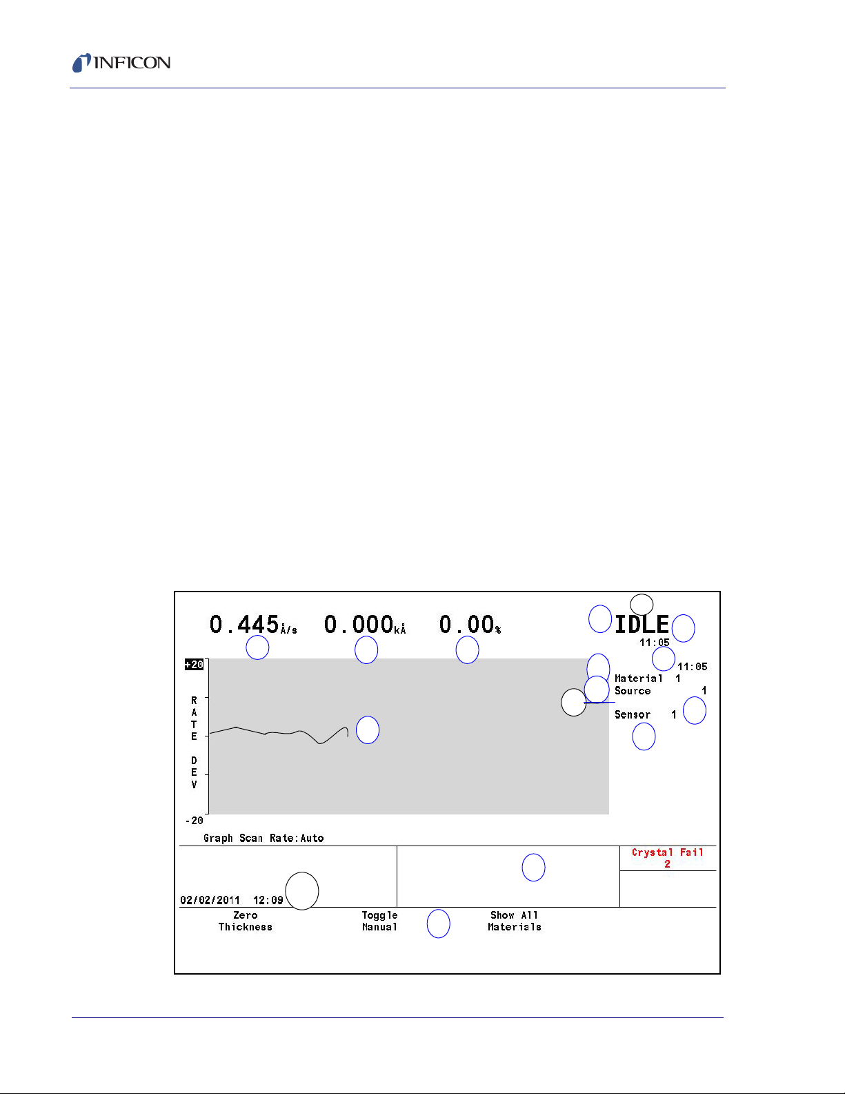
3.3.2 Operate
1
2
3
4
5
6
7
8
9
Crystal x
10
11
12
13
14
15
Crucible x
16
The default Operate display shows all six Materials, see Operate screen show all
materials on page 1-20. To display an individual Material, cursor to it an d press F3,
Show Graph. The Graph Operate display, Figure 3-4, provides information about
the current Material in process. This includes the Material, Source #, and Sensor #
currently in process. The rate, thickness, power level, state, state time, Material
time, and process time are updated once a second.
The graph gives an analog display of the Power% level or the rate deviation from
the desired rate while depositing. With the cursor on the upper Y-axis value, use
the TOGL key to choose Rate Deviation or Power% graphing. Similarly, with the
cursor on the X-axis label, use the TOGL key to choose the desired Graph Scan
Rate. These selections will apply to all six Material graphs.
Below the graph is a message area consisting of five lines. The Status Messages
area, see section 13.1, occupies the first four lines. Transient Messages, see
section 13.4 and Input Error Messages, see section 13.5, share the fifth line. This
area displays error messages, custom user messages and system status
information, such as indicating the Cygnus 2 is in Test mode. Status messages are
displayed as long as a status is true. They are put up and taken down as the
condition that set them changes. Since there is limited space for the status
messages, if too many status messages are displayed at the same time (greater
than 4), newer messages will be displayed. If they are cleared, the old messages
will appear again assuming the condition is still applicable.
Cygnus 2 Operating Manual
Figure 3-4 Show graph operate screen
IPN 074-545-P1E
3 - 6
Page 57

Cygnus 2 Operating Manual
Operate Display Description
1Rate
2 Thickness
3 Power Level
4 State of Material
5State Timer
6 Material Timer
7 Material Being Deposited
8 Source Number In Use
9 Sensor Number In Use
10 Crystal Position In Use
11 Graphical Display of Rate Deviation or Power
12 Date and Time
13 Message Area
14 Function Key Definitions
15 Crucible Position
16 State preceding Stop
During the OPERATE display, the function keys below the screen function as
explained in Table 3-1.
Table 3-1 Operate display function keys
Key Function Description
F1 ZERO
THICKNESS
IPN 074-545-P1E
F2 TOGGLE
MANUAL
F3 SHOW ALL
MATERIALS/
SHOW GRAPH
Pressing F1 resets the displayed thickness of the current
Material to zero.
Press F2 to put the Material in manual control so that the
power level is controlled by the Handheld Controller
(section 3.5.5). When in Manual, press F2 again to remove
the Material from the Manual state and place it into the
DEPOSIT state.
Press F3 to toggle between showing all Materials (if more
are running) or showing only one Material
3 - 7
Page 58

Cygnus 2 Operating Manual
Figure 3-5 6 Material display
3.3.3 Sensor Information
3.3.3.1 Sensor Information Rate/Xtal Display Description
NOTE: N/A (not available) will be displayed in these fields for diabled features or
for Sensors not in use.
Figure 3-6 Rate/Xtal display
IPN 074-545-P1E
3 - 8
Page 59

Cygnus 2 Operating Manual
Sensor (Number field)
These numbers correspond to the Sensor connector channel numbers on the
rear panel of the Cygnus 2. Use the cursor keys to position the box cursor over
the desired Sensor number. When either Switch Crystal, Rotate Sensor, Clear
S & Q Counts, or Clear Failed Crystals is pressed, that function will be
performed on the Sensor indicated by the box cursor if the Cygnus 2 is in
Ready, Stop or all active Materials are in Idle. Text will only be shown for
installed cards, unless you are in TEST.
Average Rate
This average is calculated based on a 2.5 second average of the Filtered Rate.
Raw Rate
Shows the instantaneous rate measurement. The rate fields are useful in
identifying if a Sensor’s rate measurements are becoming erratic.
% Life
The Cygnus 2 allows a 1.5 MHz frequency shift from 6.0 to 4.5 MHz on the
monitor crystal corresponding to 100% crystal life. The value shown represents
the amount of crystal life consumed; 0% corresponds to 6.0 MHz, 100%
corresponds to 4.5MHz. The amount of useful crystal life is highly dependent
on the nature of the material being deposited as well as deposition conditions.
Crystal
This field is subdivided into three categories; current position (Curr), next
position (Next), and Failed. Information is displayed in these fields only if the
Sensor has more than one position.
Curr: For a XtalTwo sensor, the Curr field will show either 1 or 2. 1 indicates the
active crystal of the dual sensor head. 2 indicates the inactive (shuttered)
crystal of the dual sensor head. For a multi-position sensor, the Curr field
indicates the current position of the sensor head.
Next: The Next field indicates the position to which the sensor head will rotate
IPN 074-545-P1E
upon pressing the CrystalSwitch function key.
Failed: The Failed field indicates the sensor head positions containing failed
crystals.
Q Count (Crystal Quality value field)
This field displays the value currently accumulated in the Crystal Quality
counter when active. Delay indicates the Crystal Quality counter is not active.
The Crystal Quality counter will become active five seconds after entering
DEPOSIT and if the Crystal Quality parameter is non-zero, see page 5-9.
3 - 9
Page 60

Cygnus 2 Operating Manual
S SIngle (Crystal Stability value field)
This field displays the positive single frequency shift currently in the Crystal
Stability counter, see page 5-9.
S Total (Crystal Stability value field)
This field displays the positive total frequency shift currently accumulated in the
Crystal Stability counter.
3.3.3.2 Crystal Life and Starting Frequency
On the Sensor Information RATE/XTAL display, crystal life is shown as a
percentage of the monitor crystal’s frequency shift, relative to the 1.50 MHz
frequency shift allowed by the Cygnus 2. This quantity is useful as an indicator of
when to change the monitor crystal to safeguard against crystal failures during
deposition. It is normal to change a crystal after a specific amount of crystal life
(% change) is consumed.
It is usually not possible to use a monitor crystal to 100% of crystal life. Useful
crystal life is dependent on the type of material being deposited and the resulting
influence of this material on the quartz monitor crystal. For well-behaved materials,
such as copper, at about 100% crystal life the inherent quality, Q, of the monitor
crystal degrades to a point where it is difficult to maintain a sharp resonance and
therefore the ability to measure the monitor crystal’s frequency deteriorates.
When depositing dielectric or optical materials, the life of a gold, aluminum or silver
quartz monitor crystal is much shorter— as much as 10 to 20%. This is due to
thermal and intrinsic stresses at the quartz-dielectric film interface, which are
usually exacerbated by the poor mechanical strength of the film. Many organic
materials deposit as non-rigid films which causes the crystal’s Q to fall rapidly. For
these materials, the %Life of the quartz has very little to do with the monitor
crystal’s failure.
3.3.3.3 Function Key Selection Choices
To enable the function keys for the Sensor Information Rate/Xtal Display, move the
cursor key to a Sensor number.
F1 Switch Crystal
To initiate a crystal switch for the Sensor number selected, press F1. The
crystal switch will be done on the Sensor indicated by the box cursor. Use the
cursor arrow keys to position the box cursor.
F2 Rotate Sensor
If the Sensor number chosen is a XtalSix, Xtal12 or Generic sensor type, press
F2 to sequentially rotate the sensor head through all positions. This is useful to
initialize a multi-position sensor after replacing failed crystals. The action is
IPN 074-545-P1E
3 - 10
Page 61

Cygnus 2 Operating Manual
taken on the Sensor indicated by the box cursor if the Cygnus 2 is in Ready,
Stop or all active Materials are in Idle. Failed crystal numbers are shown in the
Failed column under Crystal.
Generic Sensor Status showing which crystals are good and which are failed
relative to the current position is displayed in the bottom region of the table.
This information is not retained upon leaving the Sensor Information display. To
re-gain this information, press F2 again.
F3 Clear S & Q Counts
Press F3 to clear the Quality and Stability counters for the Sensor chosen by
the box cursor.
F4 Clear Failed Crystals
Pressing F4 resets the status of the Sensor that the box cursor is on for failed
Sensors and crystal positions.
3.3.3.4 Sensor Information Type/Freq Display Description
Figure 3-7 Type/Freq display
IPN 074-545-P1E
Sensor
Sensor identifies the Sensor channel. Failed Sensor numbers appear in red.
Sensor Type
Shows the Sensor type configured for the Sensor channel.
Z-Ratio
This two-column field displays the type and value of the Z-Ratio being used for
the given Sensor.
3 - 11
Page 62

Cygnus 2 Operating Manual
Matl indicates the Z-Ratio being used for thickness calculation is the value
found in the Material parameter Z-Ratio.
Auto indicates the Cygnus 2 Auto-Z feature is used for thickness calculations.
Auto-Z continually calculates the Z-Ratio for the "as deposited" film. If the
Cygnus 2 suddenly lost the ability to calculate Auto-Z, Auto would change to
either Matl or Sens. Matl has the same meaning as described above, Sens
indicates the last calculated Auto-Z value (prior to failure) is used for thickness
calculations for this Sensor.
The Cygnus 2 determines to use Matl or Sens depending on the frequency of
the fundamental resonance. If the fundamental frequency closely matches the
last valid fundamental frequency prior to Auto-Z failure, the Cygnus 2 will use
the Sens value. Otherwise the Cygnus 2 will use the Matl value.
Act(ivity)
Activity is a measure of the Sensor circuit health or ability to conduct current.
The values range from a maximum of 800 (healthiest) to a minimum of 0 (least
healthy).
The Activity value is useful for predicting when a crystal needs to be replaced.
If a crystal is about to fail, its series resistance will increase, allowing less
current to flow through the crystal and hence the Activity value will decrease.
The closer the Activity value is to zero, the more imminent a crystal failure.
Activity also can be used to gauge the health of the sensor head electrical
contacts. For example, if a new monitor crystal is placed into the sensor head
and has a crystal life of near 0%, but the Activity value for this crystal is lower
than 550, this indicates the sensor head or in-vacuum cable is in need of repair.
Frequency
This field is subdivided into two categories: Fundamental and
Anharmonic.The Fundamental frequency will be shown for all working
Sensors. If Auto-Z is in effect for the Sensor, the Anharmonic frequency will
also be shown. Frequency value will be displayed.
3.3.3.4.1 TEST XIU
To test any XIU (Crystal Interface Unit), move the cursor onto the respective
Sensor number. Pressing F1 then initiates the XIU self test. The XIU self test
determines whether the crystal interface unit (XIU) and measurement card pair
is operating properly. "XIU Test Passed" message will appear to indicate this.
"XIU Test Failed" message will appear when there is a defect in the XIU itself,
the XIU interface cable or the measurement card.
For the XIU self test to work properly, the XIU must have the six inch BNC cable
(IPN 755-257-G6) attached and must be disconnected from the sensor
feedthrough.
IPN 074-545-P1E
3 - 12
Page 63

3.3.4 Sensor Screen
From the main MENU display, placing the cursor on Sensor and pressing MENU
brings up the Sensor display.
The Sensor Overview display, see Figure 3-8, shows the current configuration for
all six Sensors.
Figure 3-8 Sensor overview display
Cygnus 2 Operating Manual
Moving the cursor onto one of the Sensor numbers and pressing F1 Select Sensor
brings up the Sensor display
See section 4.1.2, Sensor Parameters, on page 4-2 for programming details.
IPN 074-545-P1E
3 - 13
Page 64

3.3.5 Source
The Source Overview display, see Figure 3-9, shows the current configuration for
all six Sources.
Figure 3-9 Source overview display
Cygnus 2 Operating Manual
Once the right cursor key has been used to move to one of the six Sources, the
Select Source function key will appear. Pressing F1 will then display the Source’s
parameter screen.
The Source display allows configuring the selected Source.
See section 4.2.2, Source Parameters, on page 4-5 for programming details.
IPN 074-545-P1E
3 - 14
Page 65

3.3.6 Material
This display is organized into eight sub pages accessible thru the Select Menu
described below.
See Chapter 5, Material Set-Up for programming details and screen displays.
3.3.6.1 Overview Page
The Material Overview display, see Figure 3-10, shows all 6 available Materials.
Materials are initially shown as Material 1 to Material 6. Once a chemical formula
or other name has been assigned, that name will be shown. See section 5.1.2,
Material Definition, on page 5-2
Figure 3-10 Material overview page
Cygnus 2 Operating Manual
3.3.6.2 Source Page
IPN 074-545-P1E
The Material Source page allows entering or editing Density, Z-Ratio, Crucible to
use, Control Loop type and associated control loop parameters. The operating
limits for Min. and Max Power are also defined here. If desired, a Recorder Output
(one of the unused standard six or optional additional six analog outputs) can be
selected for Filtered Rate, Thickness, Rate Deviation or Power and the full scale
Range value selected. See section 5.1.3, Material Source Page Parameters, on
page 5-3.
3 - 15
Page 66
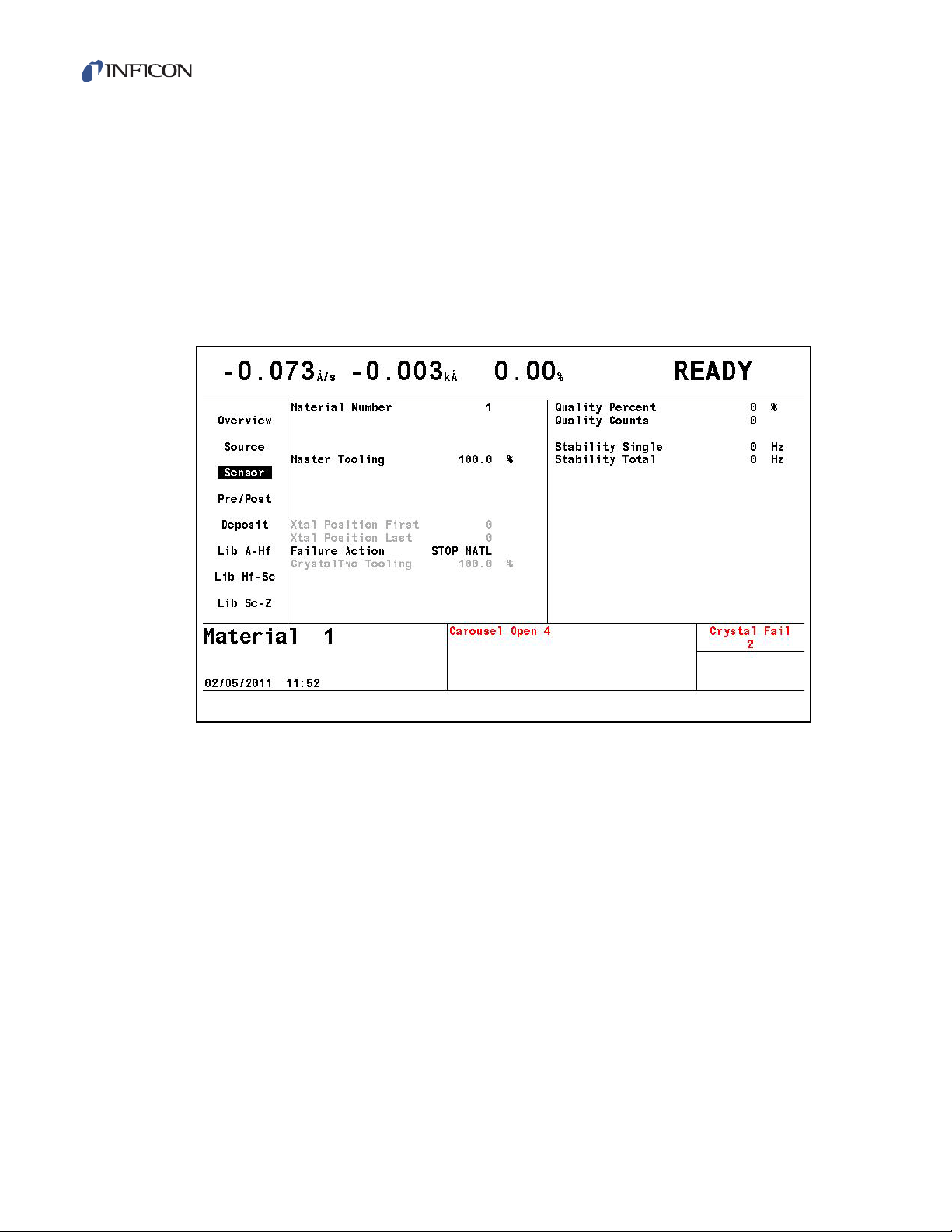
Cygnus 2 Operating Manual
3.3.6.3 Sensor Page
The Material Sensor page, see Figure 3-11, allows selecting the Tooling factor.
Other choices will be shown according to the Sensor Type. If the Sensor is a
CrystalTwo, the Tooling factor for the secondary crystal can be specified. In the
case of a multi-position rotary sensor head, the range of crystal positions to use can
be specified.
In addition, Quality and Stability settings are available to force a crystal switch to a
backup crystal when the primary crystal starts to become unstable.
Figure 3-11 Material sensor page
3.3.6.4 Pre/Post Page
Up to three pre-deposition phases with rise times, power levels and soak times can
be specified. Also, Auto Soak 2 can be enabled as well as Shutter or Control Delay.
See section 5.1.5, Pre/Post Screen Deposit Page Parameters, on page 5-10.
3.3.6.5 Deposit Page
Set the desired deposition rate, Final Thickness, Thickness Limit, Time Limit, Rate
Filter Time, Time Power Avg Time, Ion Assist Deposit, and the state to enter after
reaching Final Thickness.
Two new rates can be specified while in Deposit and RateWatcher can be enabled.
See section 5.1.7, Deposit Page Parameters, on page 5-14.
3 - 16
IPN 074-545-P1E
Page 67

3.3.6.6 Lib A-Hf, Lib Hf-Sc, Lib Sc-Z Sub-Displays
These three libraries allow convenient selection of a Material by its chemical
formula along with the correct density and Z-Ratio values. Cursor to a Material
formula, then press F1 Define Material to select that Material. The Material/Source
display will be shown where the remaining parameters can be entered. See section
5.1.2, Material Definition, on page 5-2.
3.3.7 General
The General screen is organized into eight sub screens described below.
See Chapter 6, General Parameters for programming details and screen displays.
3.3.7.1 Process Page
The Process page shows global parameters and allows editing them.
Figure 3-12 Process page
Cygnus 2 Operating Manual
IPN 074-545-P1E
Thickness Eq 1, 2 and 3. . . . . . . . . allows summing of thicknesses from up to 6
Sources for use in conjunction with a logic
statement Thick Sum event.
See section 6.2, General Process Page, on page 6-1
3.3.7.2 DACs Page
Polarity and full scale voltage for all DAC outputs are configured here. 0 output
corresponds to 0 Volts. See section 6.3, DACs Page Parameters, on page 6-2.
3 - 17
Page 68

Cygnus 2 Operating Manual
3.3.7.3 Comm Page
Datalogging of crystal data is enabled here and RS232 and optional Ethernet
parameters are entered.
Datalog Xtal Info
RS232 / Baud Rate/ Protocol
Ethernet / IP Address/ Net Mask
See section 6.4, COMM Page Parameters, on page 6-3.
3.3.7.4 Message Page
Ten messages of up to 19 characters each can be entered. Display of messages
can be turned on and off using Logic statements.
See section 6.5, MESSAGE Page Set-up, on page 6-5.
3.3.7.5 Date/Time Page
Toggle between date formats and enter the current date and time.
Date Format . . . . . . . . . . . . . . . . . . . Calendar/ Day/ Month/ Year
System Time . . . . . . . . . . . . . . . . . . See section 6.6, DATE / TIME Set Up, on
3.3.7.6 Test Page
Allows executing the programmed Material with a dummy rate signal.
Test. . . . . . . . . . . . . . . . . . . . . . . . . . On/Off
Time Compressed . . . . . . . . . . . . . . No/Yes to speed up all times by factor of 10
Advanced Test . . . . . . . . . . . . . . . . . On/Off. Responds to crystal failures in "On"
See section 6.7, TEST Page Set Up, on page 6-7.
3.3.7.7 Lock Page
Allows setting lock codes to prevent parameter changes or file access.
Program Lock Code/ File Access Code
See section 6.8, LOCK Page Code Set-up, on page 6-8.
3.3.7.8 Audio/Visual Page
page 6-6.
mode.
IPN 074-545-P1E
3 - 18
Audio Feedback: turns key beep on or off.
LCD Dimmer Time: 0 disables, sets time in minutes for screen to be turned off after
no keys pressed and no Materials are running7.
See section 6.9, AUDIO / VISUAL Page Set Up, on page 6-9.
Page 69

3.3.8 Digital I/O
The Digital I/O displays show configuration of all inputs, see Figure 3-13, and
outputs, see Figure 3-14, and allows configuring inputs and outputs on the three
possible I/O boards. See Chapter 7, Digital I/O for programming details.
Figure 3-13 All inputs display
Cygnus 2 Operating Manual
NOTE: On All Input and All Output pages, active inputs and outputs are displayed
in a standard font. Inactive inputs and outputs are displayed in a shadow
font.
Figure 3-14 All outputs display
IPN 074-545-P1E
3 - 19
Page 70

Cygnus 2 Operating Manual
3.3.9 Logic
100 logic statements can be set up. Logic statements are evaluated sequentially,
10 times per second, while the Cygnus 2 is powered up.
See Chapter 8, Logic Statement Set-Up for programming details.
3.3.10 Maintenance
The Maintenance display is organized into two subscreens: Source
Maint(enance)and Sys(tem) Status.
See Chapter 10, Maintenance and Calibration Procedures for programming
details.
3.3.11 Counter / Timer
See Chapter 11, Counters & Timers.
3.3.12 USB Storage
Config. . . . . . . . . . . . . . . . . . . . . . . . allows saving and retrieving configuration
Datalog. . . . . . . . . . . . . . . . . . . . . . . shows datalog files on USB storage device.
Screen Shot . . . . . . . . . . . . . . . . . . . shows Print files on USB storage device.
See Chapter 12, USB Storage.
3.3.13 Programming Guidelines
1 Define Materials.
To define Materials, the MATERIAL pages of the MATERIAL screen are used.
Each of up to 6 distinct Materials used must be defined. The Material definition
includes rate, density, Z-ratio, tooling, soak power settings, thickness,
RateWatcher, rate ramps, time limits and whether to STOP on max power.
Control loop characteristics also relate to the Material. Also, one Source and
one Sensor are automatically associated with each Material, for example
Source 1 and Sensor 1 are fixed to Material 1, etc. up to Source 6 and Sensor
6 for Material 6. See Chapter 5 for a detailed description for programming these
parameters.
2 Configure General parameter information.
files to and from the USB storage device.
IPN 074-545-P1E
3 - 20
The final step in defining a process is to program the parameters on the
GENERAL display. This includes the Process Thickness Equations, DAC
voltage and polarity, Communication parameters, User Messages, Date/Time,
Test mode, Lock Codes and Audio Feedback as well as LCD Dimmer time. See
Chapter 6 for a detailed description of General parameters.
Page 71

Figure 3-15 Process state diagram
Normal
Sequence
Alternate
Sequence
Hand denotes key press
Key
See Figure 3-16
Cygnus 2 Operating Manual
IPN 074-545-P1E
3 - 21
Page 72

Cygnus 2 Operating Manual
STOP
STOP
NO
NO
NO
ON
YES
YES
YES
ON / STBY
STBY POWER
FAIL
STANDBY
RESET
YES
YES
NO
NO
NO
SAVE
CURRENT
PROCESS
DATA
TURRET DELAY TIME OUT
CRUCIBLE
IN
POSITION
?
tMEMORY CHECKS
tREAD
CONFIGUR ATION
SWITCHES
tRESTORE CURRENT
PROCESS VALUES
PRECONDITION RISE
PRECONDITION SOAK
RISE TIME
1
SOURCE
SWITCH
SAME
SOURCE
AND
CRUCIBLE
?
IDLE
POWER
ZERO
?
t LOAD FILM
PARAMETERS
SOAK
TIME
1
SOAK
HOLD
INPUT
?
RISE
TIME
2
SOAK
TIME
2
SOAK
HOLD 2
INPUT
?
SHUTTER
DELAY
?
SHUTTER
DELAY
SHUTTER
DELAY
?
CONTRO L
DELAY
YES
YES
NO
MPWR
START
)
)
)
)
YES
YES
A
A
NO
NO
NO
NO
NO
YES
YES
YES
NO
READY
IDLE
WAS
TIME
POWER
USED
?
IDLE
RAMP
TIME
FEED
TIME
FEED
RAMP
ON FINAL THK
DECISION
DATA
LOG
UPDATE
THICKNESSFINAL
TIME ELAPSED
XTAL FAIL
TIME
ELAPSED
FINAL THK
XTAL FAIL
?
RATE
RAMP
FINAL THICKN ESS
RATE RAMP THICKNESS
XTAL FAIL
FINAL THK
THK LIMIT
XTAL FAIL
?
XTAL
SWITCH
SELECTED
?
DEPOSIT
RATEWATCHER
DEPOSIT
RETAIN
THICKNESS
AT
“STOP” VALUE
ZERO
THICKNESS
PROCESS
CONTINUE
?
GOOD
XTAL
?
SWITCH
XTAL
DESIRED
RATE
=
0.0
YES
NO
XTSW
TIME
POWER
SELECTED
?
“TO
FAILU RE
ACTION
STATE”
TIME
POWER
FINAL
THICK
?
START
YES
)
)
Figure 3-16 Simplified Cygnus 2 state sequence diagram
IPN 074-545-P1E
3 - 22
Page 73

3.4 State Descriptions
Table 3-2 State descriptions
Cygnus 2 Operating Manual
STATE CONDITION RELAY CONTACT
STATUS
1. READY The Cygnus 2 will accept a START
command.
2. CRUCIBLE SWITCH
(Crucible Sw)
3. PRECON RISE Source power rises to Precondition power
4. PRECON SOAK Source is maintained at precondition
During this state, the crucible turret is
being moved from its current position to the
one called out for the given Material. If the
idle power of the Source in use is not zero
the power is set to zero before the crucible
position changes. Cygnus 2 advances to
next state when turret input goes low for
the programmed position or turret delay
has elapsed (depending on parameter
settings).
level over the precondition rise time.
[PreCon Rise Time]
power level for the precondition soak time.
[PreCon Soak Time, PreCon Soak Power]
Source
Shutter
Inactive Inactive 0
Inactive Inactive 1
Inactive Inactive 2
Inactive Inactive 3
Sensor
Shutter
REMOTE
COMM
ENCODES
5. RISE 1 Source is rising to Soak Power 1 level.
[Rise Time 1]
6. SOAK 1 Source is being maintained at Soak Power
1 level. [Soak Time 1, Soak Power 1]
7. RISE 2 Source is rising to Soak Power 2 level.
[Rise Time 2]
IPN 074-545-P1E
8. SOAK 2 Source is being maintained at Soak Power
2 level. [Soak Time 2, Soak Power 2]
9. SHUTTER DLY Rate is being controlled. Advances to
Deposit State once the Source is in Rate
Control within Shutter Delay Accuracy for 5
seconds.
10. DEPOSIT Rate control. [Rate, Final Thickness, PID
Control, Process Gain, Primary Time
Constant, System Dead Time]
11. RATE RAMP 1 Rate control, desired rate changing. [New
Rate 1, Start Ramp 1, Ramp Time 1]
12. RATE RAMP 2 Rate control, desired rate changing. [New
Rate 2, Start Ramp 2, Ramp Time 2]
Inactive Inactive 4
Inactive Inactive 5
Inactive Inactive 6
Inactive Inactive 7
Inactive Active 8
Active Active 9
Active Active 10
Active Active 11
3 - 23
Page 74

Cygnus 2 Operating Manual
Table 3-2 State descriptions (continued)
STATE CONDITION RELAY CONTACT
STATUS
13. TIME POWER Crystal failed; Source maintained at
Source
Shutter
Active Inactive 12
Sensor
Shutter
average control power and average rate
prior to crystal failure. [Failure Actions]
14. Manual Manual is entered via front panel key or
remote communications command.
Thickness is incrementing if Source
shutter is open. The Source power is
controlled by the hand-held controller or
remote communications
15. (Non Deposit
Control) NonDep
CNTL
The state is entered after the pre-deposit (if
"Dep after Pre-dep" parameter set to no) or
via external stimulus (remote command,
Active or
Inactive
depending
on the state
when
manual is
entered.
Shutter can
be opened
or closed by
the operator
via remote
communications
during
manual.
Inactive Active 14
Active
Shutter can
be opened
or closed by
operator via
remote
communications
during
manual.
digital input) or after deposit if "On Final
Thickness" set to Non-Deposit Control.
Thickness is not incrementing. The Source
power is controlled to the desired rate by
the control loop.The state is ended via
external stimulus.
REMOTE
COMM
ENCODES
13
16. NonDep Hold Non-deposit hold is entered when in
non-deposit control and there are no
available crystals to continue the control if
the time power option had been chosen.
Non-deposit hold can also be entered from
time power using the RL3 Remote
command. Thickness is not incrementing.
The Source power is maintained at the
average control power prior to the crystal
failure. Both aggregate rate and power can
be adjusted via. remote communications.
The state is ended via external stimulus.
17. FEED RAMP Source changing to Feed Power level.
[Feed Power, Feed Ramp Time]
18. FEED Source maintained at Feed Power level.
[Feed Time]
19. IDLE RAMP Source changing to Idle Power level. [Idle
Ramp Time, Idle Power]
Inactive Inactive 15
IPN 074-545-P1E
Inactive Inactive 16
Inactive Inactive 17
Inactive Inactive 18
3 - 24
Page 75

Table 3-2 State descriptions (continued)
Cygnus 2 Operating Manual
STATE CONDITION RELAY CONTACT
STATUS
Source
Shutter
20. IDLE Source resting at Idle Power; will accept a
START command.
21. STOP The respective Material’s Source output is
set to zero power. The Material’s display is
frozen at the last thickness value.
NOTE: In STOP the Cygnus 2 will accept a START provided a valid crystal is available for the Material being
started.
Inactive Inactive 19
Inactive Inactive 20
Sensor
Shutter
3.5 Special Features
The Cygnus 2 has several special features to enhance the performance of the
instrument.
3.5.1 Crystal Switching
The Cygnus 2 offers a choice of Single, XtalTwo (CrystalTwo®), XtalSix
(CrystalSix®), Xtal12 (Crystal12®), or Generic sensors. The CrystalTwo,
CrystalSix, Crystal12, and Generic sensors provide one or more backup crystals in
case a crystal fails during deposition. Sensor types are specified on the Sensors
screen.
REMOTE
COMM
ENCODES
The XtalTwo option requires the 779-220-G1 or 779-220-G2 XTAL2 Switch. The
XTAL2 Switch is connected to any Sensor input through an XIU package.
All multi-position and shuttered sensors require the Pneumatic Actuator Control
Valve, part number 750-420-G1, and a feedthrough with an air tube.
A crystal switch will automatically occur when:
IPN 074-545-P1E
The Cygnus 2 is configured for a XtalTwo (CrystalTwo) sensor type, a Material
is STARTed or running and there is another good crystal available when the
active crystal fails.
The Cygnus 2 is configured for a XtalSix, Xtal12 or Generic, a Material is
STARTed or running, and there is at least one good crystal left in the carousel
when the active crystal fails.
Using a XtalSix or Xtal12 and pressing START if the current position is not
within the First/Last Xtal position range listed on the Sensor page of the
Material screen.
S & Q levels are exceeded while in deposit.
A crystal switch will NOT automatically occur:
3 - 25
Page 76

Cygnus 2 Operating Manual
During a state of STOP, READY or IDLE.
When the designated Sensor fails during pre-deposit. (A Stop Material will
occur if the failure action is configured for Time Power.)
During deposition if the secondary crystal of a XtalTwo switch fails, or the last
good crystal of a XtalSix, Xtal12 or Generic fails. (In either case a
TIME-POWER, STOP Material, POST DEPOSIT, or STOP ALL will occur,
depending on the failure option chosen.)
A crystal switch can be manually executed via the front panel, handheld controller,
remote communications, or logic statements when the system is configured for a
multi-position sensor.
NOTE: When crystal switching with the handheld controller, the Cygnus 2 must be
on the Sensor Information screen and the cursor on the appropriate
Sensor number.
3.5.1.1 XtalTwo (CrystalTwo)
In the case of the XtalTwo (a Dual Sensor head with a 779-220-G1 or 779-220-G2
XTAL 2 Switch), the CrystalSwitch output must be wired so that it simultaneously
energizes the Pneumatic Shutter Actuator Control Valve which applies the air
pressure to actuate the dual sensor shutter mechanism and the RF relay in the
XTAL 2 Switch, exposing crystal #2 while covering crystal #1 and rerouting the RF
signal. This allows the dual sensor to be operated with only one oscillator kit and
requires only one Sensor connection at the Cygnus 2.
Power-up initialization is performed on a dual sensor to verify that the secondary
crystal is good.
If a crystal fail occurs while in Deposit, the Cygnus 2 will switch to the second
crystal and continue. The Failed Crystal list can be cleared while in Deposit by
pressing the F4 function key on the Sensor Information screen with the cursor
positioned on the appropriate Sensor number. While in Ready, the Failed Crystal
list can also be cleared by executing a crystal switch with the Hand held controller
or by pressing the Switch Crystal function key in the Sensor Information screen or
via communications command RG23 (Switch Sensor) see section 9.4.31, Remote
General Action, on page 9-42. A good crystal must be available to switch to in the
case of using the crystal switch method.
IPN 074-545-P1E
3 - 26
Page 77

3.5.1.2 XtalSix (CrystalSix)
On power-up, all crystals are read to determine how many good and bad crystals
are present. The Cygnus 2 uniquely identifies and tracks all six positions in the
CrystalSix.
During deposition, the Cygnus 2 will automatically switch to the next position with
a good crystal when there is a crystal failure. When the last good crystal fails the
Xtal Fail message is displayed, the Xtal Fail state becomes true and the Cygnus 2
will go directly to Time Power, POST DEP, STOP Material or STOP ALL, as
appropriate.
When the Sensor selected is a XtalSix, the relay contacts are pulsed closed for one
second, opened for one second, closed for one second, then opened for each
position. The first one second closure will advance the CrystalSix carousel into an
intermediate position between two crystals. Opening the closure for one second
allows the ratchet mechanism to relax whereupon the second contact closure
advances the next crystal into the proper position.
3.5.1.3 Xtal12 (Crystal12)
Cygnus 2 Operating Manual
On power-up, Cygnus 2 will rotate the Sensor until position 1 is detected. It will
continue to rotate through the other 11 positions to determine the state of all
crystals. At the conclusion of the sequence, the Sensor Information screen shows
the Sensor in position 1 and the position number of any failed crystals. The
Crystal12 has resistors electrically in parallel for each of the 12 positions. The
Cygnus 2 verifies that the resistance value is correct at each position. If the value
is not as expected, the Cygnus 2 pulses again and rechecks the position. If position
1 is not detected or after 13 pulses of the wrong value, the Cygnus 2 reports a
Crystal Sw Fail message. In that case, all crystals are also marked as failed, except
for current position status.
When the carousel is removed from the Sensor for crystal replacements, the
Cygnus 2 displays Carousel Open. This message also appears if the connection
between the XIU (oscillator) and the sensor is absent. After the carousel is
IPN 074-545-P1E
replaced, the Cygnus 2 assumes the current position is 12 and all crystals are
failed. A Crystal Switch or Rotate Sensor function must be initiated in the Sensor
Information screen or via Remote Communication to enable the Cygnus 2 to
catalog the state of all crystals and to return to position 1. This must also be done
after the Sensor type has been changed to Xtal12. The Rotate Head function is
permitted only if the Material is in Ready, Stop or Idle.
During deposition, the Cygnus 2 will automatically switch to the next position with
a good crystal when there is a crystal failure. When the last good crystal fails, the
CrystalFail message is displayed, the Xtal Fail state becomes true and the Cygnus
2 will go directly to Time Power or STOP ALL, POST DEP, STOP Material, as
appropriate.
3 - 27
Page 78

Cygnus 2 Operating Manual
When configured for a Xtal12, the relay contacts are only pulsed closed for one
second then opened again once for each position. There is no intermediate
position.
3.5.1.4 Generic Sensor Crystal Switching
Selecting Generic as the Sensor type enables sequential crystal switching for the
# Positions selected (maximum of 12). Upon a crystal switch, the Switch Output will
first close for the Pulse On time and then open for the Pulse Off time. The setting
# Pulses determines how many On/Off pulse sequences will occur for each
movement to the next crystal position. The Cygnus 2 will not keep track of which
position the Generic Sensor is on nor will it keep track of which crystals are good
and which are failed. The Position Selection feature is not available for the Generic
sensor.
After a crystal switch sequence, the Cygnus 2 will attempt to find the resonant
frequency for the crystal in this position. If the Cygnus 2 does not find a good
resonant frequency for this crystal, it will again pulse the Crystal Switch Output and
attempt to find a resonant frequency at the next position. The maximum number of
attempts to find a good resonant frequency is one less than the # Positions value.
If a good resonant frequency is not found after all attempts, the Cygnus 2 will enter
the Time Power, POST DEP, STOP Material or STOP ALL state depending on the
Sensor / Option Action chosen in the Material/Sensor display.
Start resets all crystal fail flags to good.
3.5.2 Source/Crucible Selection
The Cygnus 2 can control a Source with up to 64 crucibles through up to six binary
encoded relays. This is configured by setting the Number Of Crucibles, Crucible
Outputs, Turret Feedback, Turret Input, and Turret Delay parameters on the
SOURCE page of the SOURCE screen. (See section 4.2.2, Source Parameters,
on page 4-5 for details on programming the parameters associated with
Source/crucible selection.)
To define which crucible to use for a Material, set the Cruc(ible) parameter on the
MATERIAL/Source screen. When the Material is started, if the current crucible
position is different from the one requested, the system’s turret controller will move
the crucible into position. This will be signified on the OPERATE screen by the state
indicator CRUCIBLE SW(ITCH). The Material sequencing will continue on to
Pre-condition Rise Time after either the turret delay time expires or an input
indicates the turret is in position, depending on which option is chosen. The specific
method used is determined by the parameter Turret Feedback on the SOURCE
screen.
NOTE: If the Source has been idling at a nonzero power when the START is
initiated, the power will be dropped to zero before the crucible is changed.
IPN 074-545-P1E
3 - 28
Page 79

Cygnus 2 Operating Manual
3.5.2.1 Example: Programming Turret Source Crucible Selection
Interfacing a turret source controller to the Cygnus 2 requires both hardware
connections to the turret controller and properly defining certain Cygnus 2
parameters.
Proceed to the SOURCE screen and choose the Source that is going to be defined
as the turret source. This is accomplished by Editing the chosen Source as follows:
1 Designate the Number of Crucibles; for example, four.
2 Select the Crucible Output. This defines the number of the first relay that
encodes the crucible number selected by the active Material. Relays are
defined sequentially with the first relay containing the least significant bit (LSB).
The greater the number of crucibles selected, the greater the number of relays
required. The number required is based on binary encoding (actual coding is
binary -1, with 00 representing position 1 and 11 representing position 4). Any
unused sequence of relays may be used if it is long enough to provide sufficient
selections. Outputs are NO (Normally Open).
3 Determine whether Turret Feedback is desired. This allows the turret position
controller to stop further Cygnus 2 processing until the requested turret position
is satisfied. If chosen, a turret input must be connected to the turret position
controller’s feedback signal.
Enter a Turret Delay Time which allows an adequate time for positioning to take
place. Once the delay time has expired, Cygnus 2 state processing continues.
4 The selection of a particular crucible for a Material is defined in the Material
page.
3.5.3 Auto-Z
The Auto-Z feature of the Cygnus 2 automatically determines the Z-Ratio of a
crystal. This feature is enabled on the SENSOR page of the SENSOR screen. For
the theory behind Auto-Z, see section 14.1.6, Auto-Z Theory, on page 14-9.
IPN 074-545-P1E
The following information briefly describes Auto-Z and details the conditions under
which a crystal is "unable to Auto-Z".
Auto-Z is calculated based on the slightly different mass sensitivities of the
fundamental and the first anharmonic resonances of the quartz crystal oscillator.
Therefore, the need to measure the frequencies of both the fundamental and the
first anharmonic resonances is critical.
When inserting a monitor crystal and attempting to Auto-Z, the fundamental and
anharmonic frequencies are measured to determine the status of the crystal. The
crystal status may be classified into four categories:
3 - 29
Page 80

Cygnus 2 Operating Manual
1 New Crystal
The first category is for a "new" crystal, one that does not have any material
deposited onto it. If both frequencies fall within the allowed range for new
crystals, the Cygnus 2 will allow an Auto-Z calculation with this crystal.
2 Known, Used Crystal
The second category is for a “known, used” crystal, to account for the possibility
that a person would remove a good monitor crystal and then reinsert the same
crystal. Whenever a crystal fail occurs, the last valid crystal frequencies are
stored in the Cygnus 2. Upon inserting a coated monitor crystal, the measured
frequencies for this crystal will fall outside of the allowed range for “new”
crystals. These frequencies are then compared with the stored values to
determine if this crystal is the same one as was in use prior to the crystal fail. If
the crystal is the same as used previously, and Auto-Z was being calculated
previously, the Cygnus 2 will allow an Auto-Z calculation with this crystal.
3 Unknown, Used Crystal
The third category is for an “unknown, used” crystal. This category is for a used
crystal that, upon insertion, shows measured frequencies that are outside of the
allowed “new” crystal range and also do not match the frequencies stored
within the Cygnus 2. This results in an “unable to Auto-Z” condition because the
initial frequencies of the uncoated monitor crystal are not known.
4 Unable to detect anharmonic frequency.
As mass is deposited onto the crystal, the oscillation is damped. This damping
may be severe enough that the resonance can no longer be determined. If the
Cygnus 2 loses the ability to measure the first anharmonic frequency, but is still
able to determine the fundamental frequency, the “unable to Auto-Z” message
is displayed. The Cygnus 2 will then continue to use the fundamental frequency
to monitor the deposition.
If the Cygnus 2 loses the ability to measure the fundamental frequency and all
available crystals in a multi-position sensor head are flagged as failed, the
Crystal Fail message is displayed and the Xtal Fail logic state becomes true.
5 Unable to Auto-Z
An “unable to Auto-Z” condition occurs whenever:
The anharmonic frequency cannot be measured.
The fundamental and anharmonic frequencies of the monitor crystal have
not been continuously measured from the uncoated to the coated state.
IPN 074-545-P1E
3 - 30
Page 81
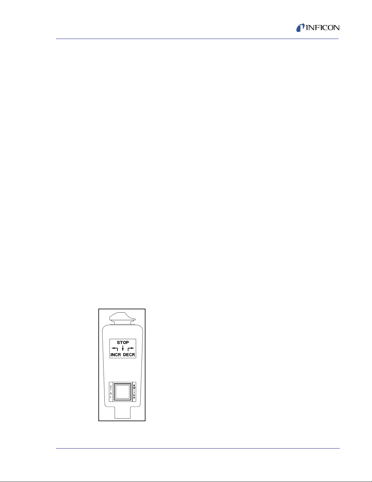
3.5.4 Rate Watcher
The Cygnus 2 includes a sample and hold function which enables periodic
sampling of the deposition rate by opening and closing the Sensor shutter. If you
are controlling inherently stable deposition sources, this function is useful in
maximizing crystal life. When RateWatcher is enabled, during deposit, rate control
will be established. The Sensor shutter will close for a designated amount of time.
The shutter will once again be opened to validate and adjust the power level. This
procedure is repeated throughout the deposition. Three Material/Deposit
parameters—RateWatcher Option, RateWatcher Time and RateWatcher
Accuracy—control this function. See section 5.1.7, Deposit Page Parameters, on
page 5-14.
3.5.5 Handheld Controller
A Handheld Controller, see Figure 3-17, is available as an accessory with the
Cygnus 2. The Handheld Controller serves as a wired remote to manually control
power, switch crystals and produce a STOP.
The Handheld Controller is attached to the Cygnus 2 with a modular plug to the
front panel.
Cygnus 2 Operating Manual
Power is affected only when in Manual mode by moving the POWER/STOP switch
laterally. Pressing to the left as idicated by the INCR arrow, increases the power.
Pressing to the right as indicated by the DECR arrow, decreases the power.
A STOP is produced by moving the POWER/STOP switch down.
When on the Sensor Information screen, a crystal switch is activated by pressing
the red button on the body of the controller.
The Handheld Controller kit includes a convenience hook for the Handheld
Controller that can be attached to the Cygnus 2’s mounting ears or some other
accessible location.
Figure 3-17 Handheld controller
IPN 074-545-P1E
3 - 31
Page 82

Cygnus 2 Operating Manual
Rate Display
40
Density (gm/cc)
--------------------------------------
Tooling %
100
-------------------------
A
sec=
3.5.5.1 Determining Soak Power with the Handheld Controller
The Handheld Controller is a useful tool that can be used to determine the
appropriate Soak Power levels. Below is an example of how a typical process Soak
1 and Soak 2 can be determined using the Handheld Controller.
Determining Soak 1
Use the Handheld Controller to slowly increase power, a few percent-per-minute.
Watch the rate until some rate increase is detected. Depending on the type of
source used, this may take several minutes. Once a non-zero rate is achieved, note
the current percent power. Use a percent or more lower than this for the Soak
Power 1 parameter.
Determining Soak 2
After ~30 - 60 seconds of Soak 1, using the Handheld Controller, again slowly
increase the power a percent at a time until the desired Deposition Rate is reached.
Use a percent or two less than this number for the Soak Power 2 parameter.
3.5.6 Test Mode
Test can be turned on or off in the General/Test display page. "Test" will be shown
in red while Test mode is active.
3.5.6.1 Standard or Time Compressed
This Cygnus 2 contains a software-controlled test mode which simulates actual
operation. In Time Compressed mode, all Material times are sped up so that a long
process can be simulated in one tenth of the time. The purpose of the test mode is
to verify basic operation and to demonstrate typical operation. The rate display
during test mode operation is:
Crystal fails are ignored in these test modes. Auto crystal switching is disabled. All
other relays and inputs operate normally.
3.5.6.2 Advanced Test
In Advanced Test mode, crystal fails are recognized and auto crystal switching is
enabled.
[1]
IPN 074-545-P1E
3 - 32
Page 83

3.5.7 USB Storage Device
CAUTION
The USB port allows storage of all parameter information, screen shots as well as
automatic datalogging information to a storage device. The maximum number of
files which may be stored depends on the storage device memory size. The
Cygnus 2 is limited to displaying 120 files as 8 pages of 15. The directories are
Config, Datalog and Screen Shot.
The parameter set may be stored under a new or existing filename and retrieved
from an existing file. A file containing the Cygnus 2 parameter set is referred to as
a configuration file. Datalog information will be saved only if the USB Datalog
Format setting in the Datalog page of the USB Storage screen is set to Comma or
Page.
Multiple files may be contained on one storage device. Filenames may be eight
characters long; extensions are used to differentiate between configuration files,
screen shots and datalogging files. All files must be contained in the appropriate
directory. Storage/retrieval from sub-directories is not allowed for screen shots and
datalog files
The Cygnus 2 supports the writing of filenames using alphanumeric characters
selected using the cursor keys. Characters A through Z and numbers 0 through 9
inclusive are available. The Cygnus 2 has the ability to display the files contained
on the memory stick. A scrolling feature is enabled to view those filenames which
cannot fit as indicated by +++ on the screen. Error messages include: Disk Full; File
Not Found; Disk Write Protected; Media Error; Disk not Found; File is Read Only.
Cygnus 2 Operating Manual
Datalog files are automatically named using the Date and Material number. See
section 3.5.9, Datalog, on page 3-35 for the Datalog string details.
Screen shots are named as DDMMYYXX or MMDDYYXX depending on the date
format setting. XX is a number that increments 0-99, resetting to 0 every day.
NOTE: A File Access Code parameter is enabled when the Cygnus 2 has a
Program lock code set. By entering a File Access Code, the Cygnus 2
parameters can be saved to, or retrieved from, the USB storage device
IPN 074-545-P1E
only without entering the Program Lock Code. (See Chapter 6, General
Parameters.)
Do not remove the USB storage device from the
Cygnus 2 while a Save or Retrieve operation is taking
place.
3 - 33
Page 84

Cygnus 2 Operating Manual
3.5.8 Lock and Access Codes
The Cygnus 2 has several forms of protection to prevent unauthorized changing of
parameters. Refer to the General setup section for a description of parameter and
Program lock codes and the File Access Code. In addition, a method of locking the
entire display is available through the remote communications. Lock codes are
entered on the General display. See Chapter 6, General Parameters.
HINT: To clear any of the locks, except the File Access Code, hold down the
CLEAR key on power up. This will clear all lock codes. HOWEVER, if no
lock codes are present, all parameters will be cleared by doing this.
3 - 34
IPN 074-545-P1E
Page 85

3.5.9 Datalog
When a Source Shutter closes, an end of deposit occurs, or following a Stop, a set
of data will be collected. The data gives the user a snap shot of the layer data as
the layer completed.
There are three ways this data can be managed:
1 USB Storage USB Datalog Format set to Page or Comma
Cygnus 2 Operating Manual
The data can be sent to a user supplied USB memory device in a data log file.
The file is saved as "MMDDYYC#.IDL" or "DDMMYYC#.IDL" depending on the
Date Format chosen in the General screen Date/Time page, see section 6.6,
where "C#" is Material Number.The data is formatted depending on the setting
of the "USB Data log format". Page format, see section 3.5.9.2, will insert a
carriage return and a line feed at the end of each line of data. In Comma format,
see section 3.5.9.3, a comma separates each piece of data.
Datalogging the crystal frequency data is an optional subset of the datalog
string and is enabled by selecting Yes for Datalog Xtal Info on the Comm page
of the General screen.
The information will be saved under a filename on the USB storage device.
Datalog files saved to the USB storage device will be automatically named
using the date and Material number. The format of the filename is
MMDDYYC#.IDL or DDMMYYC#.IDL depending on the Date Format chosen
where C# is the Material number. If the USB storage device already contains a
file with the same filename as the new datalog information, the new datalog
information will be appended to the old file.
At each Source shutter close, the datalog information will be appended to the
file (when saved to USB).
2 General Comm RS-232 Protocol set to Dlog Comma or Dlog Page
The data can also be sent to the RS-232 port if the General parameter "RS-232
Protocol" is set to "Dlog Page" or "Dlog Comma". See section 3.5.9.2 and
IPN 074-545-P1E
section 3.5.9.3 for format descriptions. The RS-232 port then becomes a "send
only" port. The port will supply the data log data and will not accept any
commands from a remote computer.
Datalogging the crystal frequency data is an optional subset of the datalog
string and is enabled by selecting Yes for Datalog Xtal Info on the Comm page
of the General screen.
3 SL16 # and SL17 # commands
The data log information is always available via Status command SL16 # (no
crystal history) or SL17 # (with crystal history) in the remote communications.
The data is returned in the standard remote communications packet as binary
words. For more information, see section 9.4.29, Status Material, on page 9-38.
3 - 35
Page 86

Cygnus 2 Operating Manual
3.5.9.1 Datalog contents:
The following values make up the data in the datalog. The data is sent in ASCII
strings when the RS-232 port is set for data logging. The data is also saved as
ASCII strings in the datalog files. The ASCII strings are made up of the labels and
values in the following list. ASCII strings are CRLF (Carriage Return Line Feed)
terminated. When the data log is requested via the remote status Material
command SL16 # (no Crystal History) or SL17 # (with Crystal History), the values
are sent in the binary format only.
Year (Integer)
Month (Integer)
Day (Integer)
Hour (Integer)
Minute (Integer)
Material x (Integer)
Material x (x is the Material number or, in data log files, the name if the name is
programmed)
Material Time seconds (Integer)
Deposit Time seconds (Integer)
Ending Thickness kÅ (Float)
Average Rate A/s (Float)
Average Rate Deviation A/s (Float)
Ending Power % (Float)
Average Power % (Float)
Where it goes next (Byte):
0 = NonDeposit Control or NonDeposit Hold
1 = Post Deposit
2 = Stop
Termination Reason (Byte) (Matches the "Cause of Stop" Remote encoding
comm, see section 13.3, STOP messages, on page 13-5:
128 = Normal termination,
127 = Manual Source shutter closing,
IPN 074-545-P1E
3 - 36
Time Power Flag (Byte) (0 = No, 1 = Yes)
Power Fail Flag (Byte) (0 = No, 1 = Yes)
Power Fail Thickness kÅ (Float) (0 if not a power fail, otherwise the thickness
when the power was lost.)
Page 87

NOTE: If Data Log Xtal Info Parameter is set to Yes, the following Crystal History
Table 3-3 Sensor 1 to 6
Cygnus 2 Operating Manual
will be sent for each Sensor, see Table 3-3. The Crystal history contains
the history of every crystal in every Sensor used in the Material. In the
Remote status command SL17 #, the crystal history for all twelve crystals
in all six Sensors is returned. If there is a minus sign in front of the Freq
value, it indicates that this crystal failed during the layer. The frequency
value shown in that case is the last valid reading obtained before the
crystal failed. If the General Comm Datalog Xtal Info parameter is set to
No, all zeros are sent in the remote status command SL17 #.
Crystal Begin
Freq
1 <Float> <Float> <Integer> <Integer> <Integer> <Integer> <Integer> <Integer>
2
3
4
5
6
End Freq BegLife EndLife Beg Activity End Activity Stability
Value
Quality
Value
Table 3-3 is extended as necessary to show all crystals in a sensor.
IPN 074-545-P1E
3 - 37
Page 88

Cygnus 2 Operating Manual
3.5.9.2 Page Format ASCII Example:
To USB Storage Device and/or RS-232 Protocol Dlog Page for Material #1.
DATE: 09/16/2010
TIME: 09:13
LAYER #: 1
MATERIAL NAME: ONE
LAYER TIME: 01:02
DEPOSITION TIME: 01:02
THICKNESS: 2.504 kAng
AVE. AGG. RATE: 40.0 Ang/S
AVE. RATE DEV.: 0.0 Ang/S
ENDING POWER: 0.0 %
AVE. POWER: 0.0 %
WHERE NEXT: Post Deposit
COMPLETION MODE: NORMAL
If Datalog Xtal Info was set to Yes, Crystal History is also sent as shown:
Sensor number of the sensor used, Crystal number of crystal(s) used, labels and
values are sent in the order displayed below.
SENSOR 1
BEG. END BEG. END BEG. END
XTAL FREQ. FREQ. LIFE LIFE ACT. ACT. STAB. QUAL.
1 5976244 5976243 0% 0% 187 189 0 0
3 5966388 5966388 0% 0% 331 328 0 0
5 5971051 5971051 0% 0% 669 674 00
If there is a minus sign in front of the Freq value, it indicates that this crystal failed
during the layer. The frequency value shown in that case is the last valid reading
obtained before the crystal failed.
IPN 074-545-P1E
3 - 38
Page 89

Cygnus 2 Operating Manual
3.5.9.3 Comma Format ASCII Example to USB Storage Device:
"09/15/2010","14:04", 1,"ONE ","00:15","00:15", 0.600, 40.0, 0.0, 0.0,
0.0,"Post Deposit ","TIME POWER"
If Datalog Xtal Info was set to Yes, Crystal History consisting of Sensor #, Crystal#,
with the crystal data for twelve crystals is sent as displayed below.
"SENSOR 1",1, 0, 0, 0, 0, 0, 0, 0, 0,2, 0, 0, 0, 0, 0, 0, 0,
0,3, …
The Dlog Comma protocol format is actually comma-and-quote delimited intended
for file importation into a spreadsheet program. When a spreadsheet program
imports a file having the comma delimited format, data groups that are strictly
numbers become value entries, data groups surrounded by quotes are stored as
labels.
For the comma delimited format, all the data fields are returned for all the crystals
in a multi-position sensor. If a crystal is not used during the deposition, the data
fields will contain zeroes.
IPN 074-545-P1E
3 - 39
Page 90

Cygnus 2 Operating Manual
3.5.10 DAC Monitoring
Cygnus 2 continually compares the actual output voltages at the DAC BNC
connectors with the internally generated values to detect external or internal
equipment malfunction. If the values do not agree, Cygnus 2 takes the following
action:
If the DAC output is assigned for Source control:
Stop the Material.
Display Source Fault message.
Set this Source Output to zero.
If the DAC output is assigned for Recorder use:
Set this output to zero.
Display Recorder Fault message.
Both types of faults remain active until a RESET is performed.
3.5.11 Trend Analysis
Along with control of the deposition process, the Cygnus 2 allows rate and
thickness information from individual quartz crystal sensors to be output to the
Digital-to-Analog (DAC) outputs. This enables mapping of an individual sensor's
information, which is useful in monitoring the change in source flux distribution
during the deposition process.
3.5.11.1 Cygnus 2 Parameters Associated with the Trend Analysis Feature
RECORDER OUTPUT. . . . . . . . . . . 0 to 12
This parameter designates which of the DAC outputs is to be used as a
recorder output. 0 indicates there is not a DAC identified with this particular
Material. Values 1 through 6 correspond to the six DAC BNC outputs on the
back of the Cygnus 2 labeled DAC 1 to DAC 6. DAC outputs 7 to 12 require the
optional DAC outputs card.
SENSOR RECORDER FUNCTION . Rate/Thick/RateDev
This parameter determines the function of the Sensor’s recorder output.
Default is (Unfiltered) Rate, not affected by the Rate Filter Time.
RECORDER RANGE. . . . . . . . . . . . 0 to 99999
IPN 074-545-P1E
3 - 40
The full scale range value selected corresponds to the value selected in the
General/DACs page for the DAC output. Default value is 100.
A recorder output cannot be associated with a DAC that is configured as a Source
output. An error message will be displayed if this is attempted.
Page 91

4.1 Sensor Set-Up Introduction
The basic Cygnus 2 has one sensor measurement board with two Sensor
channels, identified as CH1 and CH2 on the Cygnus 2 back panel and as
Sensor # 1 and Sensor # 2 on the display screens. Two more sensor measurement
boards can be added to support up to six sensors. The second sensor
measurement board will be installed in the next slot labeled CH3 and CH4 and the
associated sensors will be Sensor# 3 and Sensor# 4 etc. Each Sensor connection
requires an external oscillator (XIU) package.
Sensor Set-Up is initiated by moving the cursor to the Sensor heading on the Main
Menu and pressing MENU. To return to the Main Menu display, press MENU again.
4.1.1 Sensor Display Navigation
Cygnus 2 Operating Manual
Chapter 4
Sensor & Source Set-Up
The Sensor Overview display, see Figure 4-1, shows the current configuration of
all six possible Sensors even if only one measurement board is installed.
To make changes, use the left/right cursor to move to the appropriate Sensor, then
press F1 Select Sensor to bring up that Sensor’s screen. See Figure 4-2.
Figure 4-1 Sensor overview
IPN 074-545-P1E
4 - 1
Page 92

Cygnus 2 Operating Manual
Figure 4-2 Sensor parameter editing
4.1.2 Sensor Parameters
SENSOR TYPE . . . . . . . . . . . . . . . . Single (0), XtalTwo (1), XtalSix (2),
Values in brackets are used with the remote communication commands. This
parameter enables the Crystal Switch feature for the multi-position heads and
enables the crystal indexing feature on the handheld controller. If a
multi-position sensor is selected, the Switch Out parameter appears. Additional
parameters appear for a Generic type, see section 1.4.3.2, Sensor Parameters,
on page 1-8. This parameter cannot be changed while executing a process.
SWITCH OUT . . . . . . . . . . . . . . . . . 0 to 38
This parameter appears when the Sensor type is not Single. It designates
which of the 38 outputs is to be used as the Crystal Switch output for this
Sensor. Values 1 through 38 correspond to the appropriate output. Value 0
indicates that the Crystal Switch Output is not used. The default value is 0. If a
value other than 0 is entered, the output chosen as the Crystal Switch output is
designated as such on the Digital I/O display. The default setting for the contact
closure on this output is Normally Open.
Xtal12 (3), Generic (4). Press the TOGL key
to move through the choices. Default is
"Single".
IPN 074-545-P1E
4 - 2
Page 93

Cygnus 2 Operating Manual
SHUTTER OUT . . . . . . . . . . . . . . . . 0 to 38
This parameter designates which of the 38 outputs is to be used to activate the
Crystal Shutter for this Sensor. Values range from 0 to 38. Values 1 through 38
correspond to the appropriate output. Value 0 indicates that a shutter is not
used. The default value is 0. If a value other than 0 is entered, the output
chosen as the Crystal Shutter output is designated as such on the Digital I/O
display. The output is set to be true as long as the Material containing the
Sensor is in SHUTTER DELAY, DEPOSIT, NON DEPOSIT CONTROL,
MANUAL, or in the Sample period of the RateWatcher function. The condition
remains true until the end of POST DEPOSIT, TIME POWER, and HOLD, or
until a STOP command is received, or during the Hold period of the
RateWatcher function.
Auto-Z . . . . . . . . . . . . . . . . . . . . . . . No (0), Yes (1)
This parameter designates the method in which the Z-Ratio value will be
obtained for use in computing thickness with this Sensor. No indicates that the
Z-Ratio established in Material Definition is used. Yes indicates that the Auto-Z
calculation feature of the system is used. Auto-Z cannot be enabled on a crystal
which is “unable to Auto-Z”. Refer to section 3.5.3 on page 3-29 for details on
why a crystal is unable to Auto-Z. The default value is No for the Material
Z-Ratio.
Recorder Settings
OUTPUT. . . . . . . . . . . . . . . . . . . . . . 0 to 12
This parameter designates which of the DAC outputs is to be used as this
Sensor’s recorder output. Values range from 0 to 12. 0 indicates there is no
DAC used with this Sensor. Values 1 through 6 correspond to the six DAC BNC
outputs on the back of the Cygnus 2 labeled DAC 1 to DAC 6. DAC outputs 7
to 12 require the optional DAC output card.
FUNCTION. . . . . . . . . . . . . . . . . . . . (Unfiltered) Rate (0), Thick (1), RateDev (2)
This parameter determines the function of the Sensor’s recorder output.
IPN 074-545-P1E
Default is 0 for the unfiltered Rate, not affected by the Rate Filter Time.
RANGE . . . . . . . . . . . . . . . . . . . . . . 0 to 99999 (for Rate and Thick)
The full scale range value selected corresponds to General Parameter DAC
Scale and Polarity. Default is 100. Grayed out if RateDev is selected.
4 - 3
Page 94

Cygnus 2 Operating Manual
4.2 Source Set-Up Introduction
The Cygnus 2 provides the capability to configure the six Source control channels.
Each Source control channel is treated as an individual device.
Source Set-Up is initiated by moving the cursor to the Source heading on the Main
Menu and pressing MENU. You may return to the Main Menu display by pressing
MENU again.
4.2.1 Source Navigation
The Source Overview page shows the current configuration of all six Sources.
Figure 4-3 Source overview page
4 - 4
To make changes, use the left/right cursor to move to the appropriate Source, then
press F1 Select Source to display that Source’s screen
IPN 074-545-P1E
Page 95
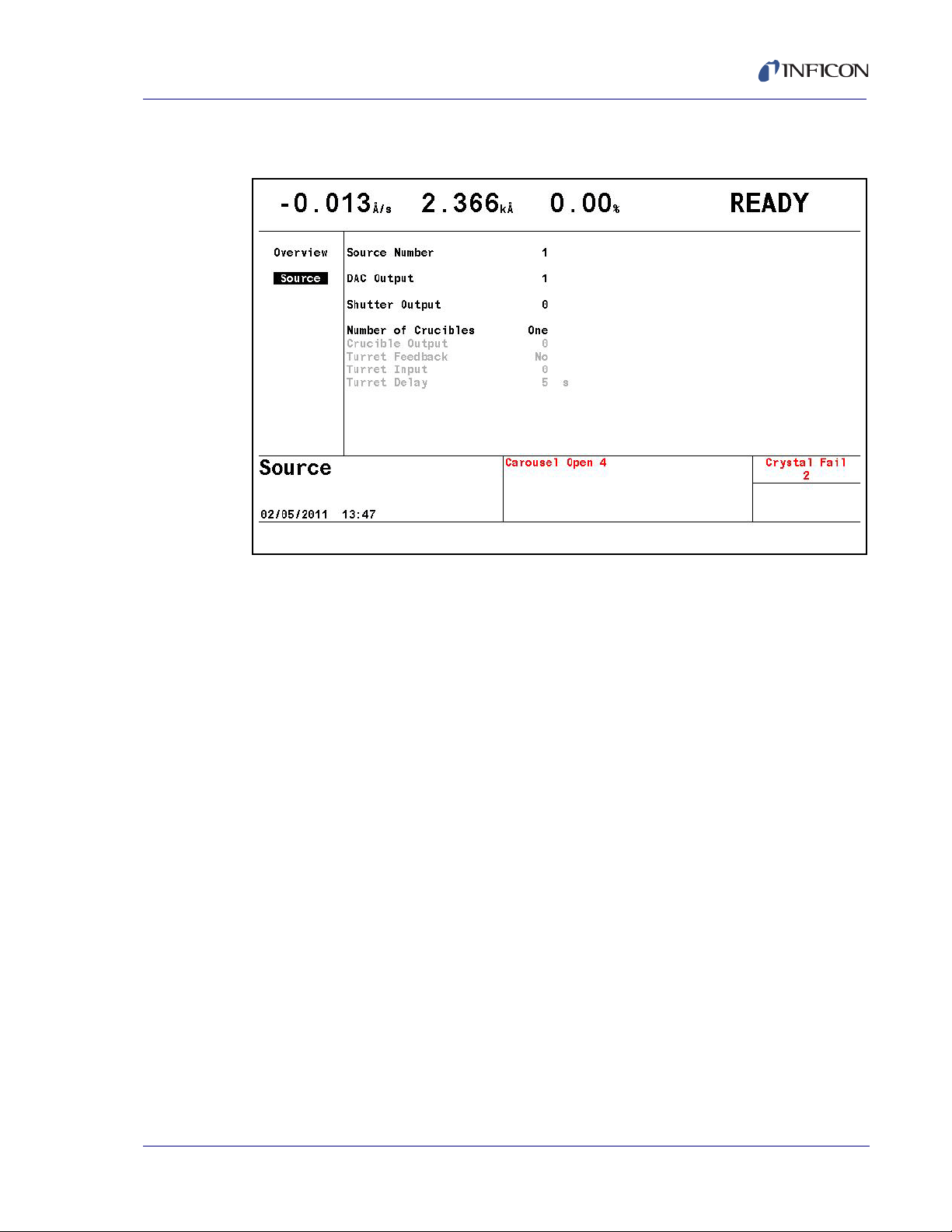
4.2.2 Source Parameters
Figure 4-4 Source parameter page
Cygnus 2 Operating Manual
The following parameters can be edited for each of the 6 Source control channels.
SOURCE NUMBER . . . . . . . . . . . . . 1 to 6
Enter the number of the Source to be edited.
DAC OUTPUT . . . . . . . . . . . . . . . . . 0 to 12
This parameter designates which of the DAC outputs is to be used as a Source
output. Values range from 0 to 12, with 0 indicating there is no DAC identified
with this particular Source. Values 1 through 6 correspond to the six DAC BNC
outputs on the back of the Cygnus 2 labeled DAC 1 to DAC 6. DAC outputs 7
to 12 require the optional DAC outputs card.
SHUTTER OUTPUT. . . . . . . . . . . . . 0 to 38
IPN 074-545-P1E
This parameter designates which of the 38 outputs is to be used as the Source
Shutter relay. Values range from 0 through 38. 0 indicates that a shutter is not
used and values 1 through 38 correspond to the appropriate relay or open
collector type output. The default value is 0. If a value other than 0 is entered
the relay chosen as the Source Shutter relay is designated as such in the
Digital I/O Display. When running a Material containing the Source for which the
Shutter Output parameter is programmed, the logic condition is set to be true
when the Material is in DEPOSIT, TIME POWER, RATE RAMPS or MANUAL.
The condition remains true until the end of DEPOSIT or until a STOP command
is received.
4 - 5
Page 96

Cygnus 2 Operating Manual
NUMBER OF CRUCIBLES . . . . . . . One(0), Four(1), Eight(2), 16(3), 32(4), 64(5)
Values in brackets are for use with remote communication commands. Refer to
section 3.5.2, Source/Crucible Selection, on page 3-28 for an example of
programming Turret source crucible selection. This parameter can be used to
automatically index the turret position when using a multiple pocket turret
source. The value is selected using the TOGL and ENTER keys. The default
value is 0 and indicates a single pocket source. If a 0 is chosen, the parameters
Crucible Output, Turret Feedback and Turret Delay or Turret Input are grayed
out on the Display. The number of crucibles determines the number of relays
needed for the crucible output. As the relays are binary encoded (actual coding
is binary - 1, with 000 representing position 1 and 111 representing position 8),
2 relays are needed for 4 crucibles, 3 for 8, 4 for 16, 5 for 32 and 6 for 64.
CRUCIBLE OUTPUT. . . . . . . . . . . . 0 to 37
This parameter designates which of the outputs are to be used as Crucible
Outputs. Values range from 0 to 37. The default is 0 and indicates the Crucible
Output is inactive. The value entered into this parameter indicates which of the
outputs begins the sequence of outputs used as crucible control outputs. For
example, a Four(1) entered into the Number of Crucibles parameter and a 1
entered into the Crucible Output parameter will designate output relays 1 and
2 as crucible control outputs with the least significant bit of the binary coding in
relay output 1. An Eight(2) entered into the Number of Crucibles parameter and
a 1 entered into the Crucible Output parameter will designate output relays 1,
2, and 3 as crucible control outputs with the least significant bit of the binary
coding in relay output 1.
TURRET FEEDBACK . . . . . . . . . . . Yes (1), No (0)
Some turret source indexers provide feedback to signify when the turret is in
the proper position. This parameter allows the Cygnus 2 to accept this input
and respond accordingly. Parameter entry may be either Yes or No. Yes
indicates that Turret Feedback is expected and the Turret Input parameter is
displayed on the screen. No indicates there is no Turret Feedback. The default
value is No. See the Turret Input and Turret Delay descriptions below.
NOTE: If the turret feedback is set to Yes and the Material is STARTed, the
Cygnus 2 will proceed to the CRUCIBLE SW state. If the turret input is
not received within the Turret Delay time, the Material will STOP.
TURRET INPUT. . . . . . . . . . . . . . . . 0 to 28
This parameter designates which of the 28 inputs is to be the Turret Feedback
input. Values range from 0 to 28. Values 1 through 14 correspond to the
appropriate input on I/O Relay Module 1, values 15 to 28 require the I/O Relay
Module 2. Value 0 indicates that an input for turret feedback is not used. The
default value is 0. However, an input must be assigned or the state sequence
IPN 074-545-P1E
4 - 6
Page 97

Cygnus 2 Operating Manual
CAUTION
will never proceed past the Source switching state. If a value other than 0 is
entered, the input chosen as the Turret Input is designated as such on the
Digital I/O display. Input lines are activated with a contact closure to ground.
TURRET DELAY . . . . . . . . . . . . . . . 2 to 180 s
The Turret Delay time sets the maximum amount of time the Process will
remain in CRUCIBLE SW(itch), waiting for rotation to complete without turret
feedback before proceeding to the pre-condition state. If a Turret Input signal
is expected (Turret Feedback = Yes) this is the time the Cygnus 2 will wait to
receive the input signal. If the signal is not received within this time, the Cygnus
2 will stop. If the Turret Input becomes active during the delay time, processing
continues immediately. Permissible values are 2 to 180 seconds. The default
value is 5 seconds.
The Cygnus 2 will proceed to the Pre-Condition state
after the Turret Delay time expires. This could result in
damage to your equipment if the crucible is not in
position after expiration of the Turret Delay time.
4.3 DAC Output Selection Rules
The six standard DAC outputs, DAC 1 to DAC 6, located on the back of the
Cygnus 2 and the six optional DAC outputs, DAC 7 to DAC 12, may be used for
rate control or to record rate, thickness and rate deviation. Since these outputs can
be set up for different functions, certain rules apply.
No DAC output can be set up as both a recorder output and a Source output.
If this is attempted, an error message will be displayed.
A DAC output cannot be set up for more than one Source. If this is attempted
the error message DAC Used Source # will be displayed.
IPN 074-545-P1E
A DAC output can be set up for more than one recorder output including any
combination of Material or Sensor recorders Rate/Thickness or Sensor
Rate/Thickness.
If a DAC output is set up for multiple recorder outputs that are required to be
operative at the same time, the error message Recorder Conflict will appear.
This is a non-fatal error (that is, it will not cause the Cygnus 2 to STOP) and the
message will remain until the conflict is resolved or a STOP takes place.
The priority of a recorder output that is in conflict is:
a. Filtered Rate/Thickness on the Material
b. Sensor Unfiltered Rate/Thickness from Sensor.
4 - 7
Page 98

Cygnus 2 Operating Manual
This page is intentionally blank.
4 - 8
IPN 074-545-P1E
Page 99

5.1 Introduction
The Cygnus 2 can store definition parameters for up to 6 Materials. Any Material
that is to be used must be defined. Materials can be defined by referencing the
internal Material Library containing more than two hundred cataloged materials and
by completing a series of parameter entries at the front panel.
Material Set-Up is initiated by moving the cursor to the Material heading on the
Main Menu and pressing MENU. To return to the Main Menu screen, press MENU
again.
5.1.1 Material Overview Page
The Material Overview display, see Figure 5-1, shows all 6 available Materials.
Materials are initially shown as Material 1 to Material 6. Use the right arrow cursor
to move into the Material table.
Cygnus 2 Operating Manual
Chapter 5
Material Set-Up
Figure 5-1 Material overview display
IPN 074-545-P1E
With the cursor on one of the 6 Materials, press F1 Select Material. See Figure 5-3
on page 5-3. The screen changes to show the Material screen. To assign one of
the chemical formulas with its correct density and Z-Ratio values to this Material #,
move the cursor to the appropriate library display: Lib A-Hf, Lib Hf-Sc or Lib Sc-Z.
5 - 1
Page 100

Cygnus 2 Operating Manual
5.1.2 Material Definition
Figure 5-2 Material library A - Hf display
The three Material Libraries—Lib A - Hf, Lib Hf - Sc and Lib Sc - Z— provide an
alphabetic list of materials by chemical name along with their density and Z-Ratio.
Once a Material is selected from the library listing by moving the cursor to it, press
F1 Define Material. The correct chemical formula and library name, density and
Z-Ratio values will now be imported to this Material # and the Material/Source page
will appear. To rename this Material, cursor to the name and use the keys in
cell-phone format to enter up to 15 characters.
To move among and through the Materials, use the four cursor keys.
m
IPN 074-545-P1E
5 - 2
 Loading...