

Page 1

Translation of the Original
CU1000
Operating unit
Catalog No.
560-320
From software version
2.72 (LDS3000) / 2.72 (CU1000)
jina54en1-06-(1901)
Page 2

INFICON GmbH
Bonner Strasse 498
50968 Cologne, Germany
Page 3

INFICON Table of Contents
Table of Contents
1 About these instructions ...................................................................................................................................5
1.1 Target groups ...........................................................................................................................................5
1.2 Other associated documents ....................................................................................................................5
1.3 Warnings...................................................................................................................................................5
2 Safety ...............................................................................................................................................................6
2.1 Intended use .............................................................................................................................................6
2.2 Owner requirements .................................................................................................................................6
2.3 Operator requirements..............................................................................................................................6
3 Shipment, Transport, Storage ..........................................................................................................................7
4 Description........................................................................................................................................................8
4.1 Device setup .............................................................................................................................................8
4.2 Function ....................................................................................................................................................9
4.3 Technical data ..........................................................................................................................................9
5 Installation ......................................................................................................................................................10
5.1 Connecting the control unit .....................................................................................................................10
5.2 Installing the control unit .........................................................................................................................11
6 Operation CU1000..........................................................................................................................................12
6.1 Touchscreen elements ...........................................................................................................................12
6.1.1 Measurement display elements ..................................................................................................12
6.2 Elements of the error and warning display .............................................................................................15
6.3 Settings and functions ............................................................................................................................16
6.3.1 Touch screen settings................................................................................................................. 16
6.3.2 Operator types and authorizations.............................................................................................. 19
6.3.2.1 Logging out the operator ....................................................................................................21
6.3.3 Functions .................................................................................................................................... 21
6.3.3.1 Resetting the settings.........................................................................................................21
6.3.3.2 Recording data...................................................................................................................21
6.3.3.3 Calling up information ........................................................................................................22
6.3.4 Updating the software .................................................................................................................26
6.3.4.1 Updating the software of the control unit............................................................................26
6.3.4.2 Checking and updating the software version of the MSB box............................................26
6.3.4.3 Updating the software of the I/O module............................................................................27
CU1000-operating-instructions-jina54en1-06-(1901) iii
Page 4

Table of Contents INFICON
7 Decommissioning the measuring instrument..................................................................................................29
7.1 Disposing of the device...........................................................................................................................29
7.2 Sending in the device .............................................................................................................................29
8 Appendix.........................................................................................................................................................31
8.1 CE Declaration of Conformity .................................................................................................................31
8.2 RoHS ......................................................................................................................................................32
iv CU1000-operating-instructions-jina54en1-06-(1901)
Page 5

INFICON About these instructions | 1
1 About these instructions
1.1 Target groups
These operating instructions are intended for the owner and for technically qualified
personnel with experience in leak detection technology and integration of leak
detection devices in leak detection systems. In addition, the installation and use of the
device require knowledge of electronic interfaces.
1.2 Other associated documents
Mass spectrometer module operating
instructions
Operating instructions bus module jiqb10
Operating instructions I/O module jiqc10
Protocol Descriptions jira54
1.3 Warnings
DANGER
Imminent hazard resulting in death or serious injuries
WARNING
Hazardous situation resulting in potential death or serious injuries
jiqa54
CAUTION
Hazardous situation resulting in minor injuries
NOTICE
Hazardous situation resulting in damage to property or the environment
CU1000-operating-instructions-jina54en1-06-(1901) 5 / 36
Page 6

2 | Safety INFICON
2 Safety
2.1 Intended use
The unit is intended for querying and configuring the data of the mass spectrometer
module LDS3000.
► Install, operate and service the unit only in compliance with these instructions.
► Maintain the application limits (refer to Chapter 4.3, page 10).
2.2 Owner requirements
Safety conscious
operation
Personnel
qualifications
Operate and install the device only in technically perfect working order and as
specified, in a safety-conscious and hazard-conscious manner and in compliance with
these instructions.
► Fulfill and ensure compliance with the following regulations:
- Intended use
Universally valid safety and accident prevention regulations
- International, national and local standards and guidelines
- Additional device-related provisions and regulations
► Use only original parts or parts approved by the manufacturer.
► Keep this manual available at the operating site.
► All work must be performed only by technically qualified specialists who have been
trained on the device.
► Allow personnel in training to work on the device only under the supervision of
technically qualified specialists.
► Make sure that the authorized personnel have read and understood these
instructions and all other applicable documents (refer to "Other associated
documents"), especially the information on safety, maintenance and repairs, before
starting work.
► Define responsibilities, authorizations and supervision of personnel.
2.3 Operator requirements
► Read, observe and follow the information in these instructions and the working
instructions created by the owner, especially the safety instructions and warnings.
6 / 36 CU1000-operating-instructions-jina54en1-06-(1901)
Page 7

INFICON Shipment, Transport, Storage | 3
3 Shipment, Transport, Storage
Shipment
Transport
Storage
Item Quantity
Control unit 1
Touch PIN 1
Operating instructions 1
► Please check the scope of delivery of the product for completeness after receipt.
NOTICE
Damage due to unsuitable packaging material
Transport in unsuitable packaging material can damage the device.
► ► Transport the device only in the original packaging.
► ► Keep the original packaging.
► Store the device taking into consideration the technical data, refer to Chapter 4.3,
page 10.
CU1000-operating-instructions-jina54en1-06-(1901) 7 / 36
Page 8

4 | Description INFICON
4 Description
4.1 Device setup
Fig.1:
Front view
1 Touchscreen 4 USB port
2 Status LED 5 Mounting holes
3 Rest button
Status LED
Status LED illuminated Control unit operates normally
Status LED flashing Display is set to power saving mode
Fig.2:
Rear view
1 Rating plate with control unit 3 Calibration button for calibrating
the touch screen (LCD-CAL), can
be operated with touch PIN
2 Connection for headphones 4 Connection for the cable to the
leak detector (LD)
8 / 36 CU1000-operating-instructions-jina54en1-06-(1901)
Page 9

INFICON Description | 4
4.2 Function
You can use the control unit to configure the mass spectrometer module LDS3000. It
also lets you output the data stored in the MSB box.
4.3 Technical data
Mechanical data
560-320
Dimensions (lxwxh) 106,2 mm x 128,4 mm x 49,2 mm
Electrical data
560-320
Memory capacity for measured data 16 MB
Ambient conditions
560-320
Max. altitude above sea level 2000 m
Max. relative humidity above 40 °C 50%
Max. relative humidity from 31 °C to 40°C80% to 50% (linear abfallend)
Max. relative humidity to 40 °C 80%
Storage temperature -20 °C - 60 °C
Pollution degree II
CU1000-operating-instructions-jina54en1-06-(1901) 9 / 36
Page 10

5 | Installation INFICON
5 Installation
5.1 Connecting the control unit
Establish connection of "LD" of the control unit and "Control Unit" of the MSB box with
the data cable.
The data cable on the control unit can also be connected or removed during operation.
► If needed, connect headphones or speakers to the headphones symbol.
DANGER
Hearing damage from loud volume setting
Loud volume setting can damage hearing.
► Do no set volume of headphones too loud.
10 / 36 CU1000-operating-instructions-jina54en1-06-(1901)
Page 11

INFICON Installation | 5
5.2 Installing the control unit
Fig.3:
Dimensions of the control unit in mm (inches in brackets)
• Recess for the control unit integrated in the test system.
► Push the control unit into the recess and screw it tight.
► Pull protection film from touch screen.
CU1000-operating-instructions-jina54en1-06-(1901) 11 / 36
Page 12

6 | Operation CU1000 INFICON
6 Operation CU1000
NOTICE
Damage to touch screen from incorrect operation.
The touch screen can be damaged with a hard or pointed item.
► Operate touch screen with fingers only.
6.1 Touchscreen elements
6.1.1 Measurement display elements
Fig.4:
Measurement display
12 / 36 CU1000-operating-instructions-jina54en1-06-(1901)
Page 13

INFICON Operation CU1000 | 6
1 Keyboard lock 2 Communication status 3 Data recording
4 Operator 5 Zero 6 Message
7 Tracer gas 8 Operation mode 9 Leak rate with peak hold function
10 Graphic representation of the leak
rate and the peak hold function
13 Button "Favorite 2" 14 Button "Favorite 1" 15 Menu
16 Value axis 17 Value axis
11 Time axis 12 Foreline pressure
1 - Keyboard lock
The control unit is locked or unlocked by pressing and holding the icon for the
keyboard lock.
2 - Icon for the communication status
• Icon connected: The device communicates with the mass spectrometer module.
• Icon disconnected: The device does not communicate with the mass spectrometer
module.
Establish communication:
1
Reset control unit.
2
Checking the status of the mass spectrometer module.
3
Check cable connection.
3 - Icon for the data recording
The measurement is recorded.
4 - Ser
The registered operator is shown abbreviated.
Display Meaning
Ope Operator
Sup Supervisor
Int Integrator
Ser Service
For more information, see Chapter 6.2.2., Page 20.
5 - Zero
Background suppression is active.
CU1000-operating-instructions-jina54en1-06-(1901) 13 / 36
Page 14

6 | Operation CU1000 INFICON
6 - Caution icon
Active warnings are stored in the unit.
The active warnings can be displayed via the menu "Info > History > Warnings".
7 - Tracer gas
Set tracer gas and tracer gas concentration percentage.
Display Meaning
He Helium (4He)
H2 Hydrogen
M3 E.g. H-D, 3He or H
3
8 - Operation mode
Configured operation mode
Display Operation mode
VA Vacuum
SNIF Sniff
LOW FLOW XL sniffer adapter in LOW FLOW
HIGH FLOW XL sniffer adapter in HIGH FLOW
Standby XL sniffer adapter in HIGH FLOW on
standby
9 - Leak rate
Current measurement for the leak rate.
10 - Graph
Graphic display of the leak rate Q(t).
11 - Leak rate
Time axis of the leak rate Q(t).
12 - Primary vacuum pressure (not with operation mode XL Sniffer
Adapter)
Backing pressure p1.
13 - Button "Favorite 2"
You can assign preferred parameters to this button (see Page 19 ). In Fig. 4 the button
"Favorite 2" is assigned the function "Start/Stop" for example.
14 / 36 CU1000-operating-instructions-jina54en1-06-(1901)
Page 15

INFICON Operation CU1000 | 6
Displayed
message
with details
Detailed display
further active
errors or
warnings
(if present)
To the display
further active
errors or
warnings
(if present)
WARNING
Number: 500
Pressure sensor not connected
(Value = 4.23E-2)
Further errors or warnings
To confirm
all messages
Information to
cause or remedy
to the message shown
above
501
502
14 - Button "Favorite 1"
You can assign preferred parameters to this button (see Page 19 ). In Fig. 4 the button
"Favorite 1" is assigned the function "ZERO" for example.
15 - Icon for the menu
All functions and parameters of the control unit can be accessed using the "Menu"
key .
A full display of the menu of the menu is included as a file on the USB flash drive
supplied with the LDS3000.
16 - Value axis
Value axis of the leak rate Q(t).
17 - Device of measurement
Device of measurement of the value axis.
6.2 Elements of the error and warning display
CU1000-operating-instructions-jina54en1-06-(1901) 15 / 36
You will find an overview of possible errors and warnings in the operating instructions
of the LDS3000 (mass spectrometer module), chapter "Warning and error messages".
Page 16

6 | Operation CU1000 INFICON
6.3 Settings and functions
Settings and functions of the control unit are explained in the following. You will find
the settings and functions of the mass spectrometer module LDS3000 you can set
using the control unit in the operating instructions of the mass spectrometer module.
6.3.1 Touch screen settings
The touch screen grays out the parameters if
• the user is not authorized to modify the values,
• the older version of the software run by mass spectrometer module LDS3000 does
not support this parameter.
Scaling of the Q(t)axis
Linear or logarithmic
Lin.
Log.
Control unit Display > Q(t) axis > Linear or logarithmic
Number of decades with logarithmic view
1
2
3
4
Control unit Display > Q(t) axis > Decades
Autoscale
Off (When ”Off”, you can change the appearance by pressing the intersection of the
coordinate axes, then flicking and releasing the desired axis with your finger, or by
pressing and releasing the end of the desired co-ordinate axis)
On
Control unit Display > Q(t) axis > Auto scale
Scaling of the time axis
16 / 36 CU1000-operating-instructions-jina54en1-06-(1901)
Scaling of the time axis
15 s
30 s
60 s
120 s
Control unit Display > Time axis > Time axis scale
240 s
480 s
960 s
Page 17

INFICON Operation CU1000 | 6
Display units
Measured value
display
Device of pressure
Mbar
Pa
Atm
Torr
Control unit Display > Units (display) > Pressure unit
Type of graphic display
Diagram
Bar graph
Control unit Display > Measurement view > Measurement view mode
Numeric representation of the measurements
Off
On
Control unit Display > Measurement view > Show value
Display brightness
Trigger display on the
touch screen
Assigning favorite
buttons
Display brightness
20 ... 100%
Control unit Display > Brightness > Display brightness
Selection of the trigger (leak rate threshold) displayed on the touch screen.
1
2
3
4
Control unit Settings > Trigger > Trigger sel.
The favorite buttons offer direct access to individual functions. They can be assigned
with access control "Supervisor" or higher by the user.
Favorite 1: Middle button (see Fig. 4, Page 15).
Favorite 2: Right button
Favorite 3: Button on the bottom right of the main menu.
CAL
ZERO (at AQ instead of ZERO: ZERO
AQ)
Measurement view
Start/Stop
CU1000-operating-instructions-jina54en1-06-(1901) 17 / 36
Volume
- - - (= without function)
Check CAL
Flow control
(At AQ additionally: AQ Wizard)
Page 18

6 | Operation CU1000 INFICON
View settings
Control unit Settings > Favorites > Favorite 1 (2, 3)
Display of messages
on the touch screen
Show calibration note
Show calibration
request
Warnings and error messages can be displayed on the touch screen.
Off
On
Control unit Settings > Set up > Control unit > Messages > Show
warnings
Suppress or allow the calibration note with the following content:
• Leak rate of the applied calibration leak
• No calibration should take place during the first 20 mins
OFF (suppressed)
ON (allowed)
Control unit Settings > Set up > Control unit > Messages > Show
calibration notes
The calibration request can be allowed or suppressed.
OFF (suppressed)
Display of messages
on the touch screen
Setting the audio alarm
ON (allowed)
Control unit Settings > Set up > Control unit > Messages > Show
calibration request
Warnings and error messages can be displayed on the touch screen.
Off
On
Control unit Settings > Set up > Control unit > Messages > Show
warnings
Volume of the headphones or active speaker
--- No sound
Proportional: The frequency of the audible signal is proportional to the bar graph
display or diagram height. The frequency range is 300 Hz to 3300 Hz.
Setpoint: The pitch is proportional to the leak rate. The signal sounds if the leak rate
exceeds the selected trigger value.
18 / 36 CU1000-operating-instructions-jina54en1-06-(1901)
Page 19

INFICON Operation CU1000 | 6
Pinpoint: The sound of the acoustic signal changes its frequency within a specific
range of leak rates. Range: A decade below the selected trigger threshold up to one
decade above. The sound keeps at a constant low and a constant high frequency
below and above this range, respectively.
Trigger: If the selected trigger threshold is exceeded, a two-pitch signal sounds.
Control unit Settings > Set up > Control unit > Audio > Audio alarm mode
Automatic switch off of
the touch screen
6.3.2 Operator types and authorizations
Behavior with warnings or error messages:
error, then a two-pitch signal sounds simultaneously.
The touch screen can be switched off automatically after a specific time without any
operation to save energy.
30 s
1 min
2 min
5 min
Control unit Settings > Set up > Control unit > Energy > Display off after
There are four different operator types that are distinguished by different
authorizations. The integrator is registered ex works.
Additional operators can be registered. The following table shows options for
individual operator types to register new operator types.
10 min
30 min
1 h ∞ (=never)
If the touch screen shows a warning or an
Operator registration
Viewer Operator Supervisor Integrator
- Operator
Viewer
For the types "Integrator", "Supervisor" and "Operator", a four-digit PIN must be
assigned during registration (0000 ... 9999). "0000" is assigned to all operators ex
works.
If an operator keeps the pin "0000", this operator will always be registered is during
the start up of the system (without PIN query).
A key-operated switch can be used in addition to a PIN if an I/O module is connected.
The key-operated switch is connected to the I/O module via three digital inputs (see
operating instructions of the LDS3000).
The following table shows the authorizations of individual operator types.
Supervisor
Operator
Viewer
Integrator
Supervisor
Operator
Viewer
CU1000-operating-instructions-jina54en1-06-(1901) 19 / 36
Page 20

6 | Operation CU1000 INFICON
Function Viewer Operator Supervisor Integrator
Load parameters
Save parameters
Changing
- x x x
parameters
Changing the
- x x x
display of error
information
Calling up
- - - x
factory settings
Entering
- - - x
maintenance
history
The menu "Service" is accessible only to INFICON service staff.
The saved/backed-up parameters of control unit CU1000 and of the mass
spectrometer module can be loaded from a USB stick.
Control unit Function > Data > Parameters > Load
The parameters of control unit CU1000 and of the mass spectrometer module can be
saved to a USB flash drive.
Display error
information
Parameter list display
and change
Control unit Function > Data > Parameters > Save
The type of error information can be set differently for each operator type. The
Integrator always receives the complete information.
Number: Message number
text: Brief description
Info: Expanded message information
• Only numbers
• Number and text
• Number, text and info
Control unit Function > Data > Parameter > Error info
Viewer (Operator, Supervisor)
Parameters can be displayed as an alphabetical list with names and current value s.
Each list entry is a button which, when pressed, will open the parameter's set-up
dialog box.
Control unit List > Parameters list
or:
Functions > Data > Parameters > List
Display list of
parameter change
authorizations
Parameters can be displayed as an alphabetical list with names and current change
authorizations. Each list entry is a button which, when pressed, will change access
control. Changes are possible in accordance with the hierarchy of the operator.
Control unit Functions > Data > Parameters >
Parameter Access
20 / 36 CU1000-operating-instructions-jina54en1-06-(1901)
Page 21

INFICON Operation CU1000 | 6
6.3.2.1 Logging out the operator
The operator activates access level "Viewer" to log out. "Access Ctrl > Viewer"
6.3.3 Functions
6.3.3.1 Resetting the settings
Mass spectrometer
module
Access controls
Control unit
6.3.3.2 Recording data
The settings of the mass spectrometer module can be reset to factory settings.
Control unit Functions > Data > Parameters > Reset >
MSB settings
The authorization for changing parameters can be reset to factory setting.
Control unit Functions > Data > Parameters > Reset >
Param. access control
The control unit settings can be reset to factory settings.
Control unit Functions > Data > Parameters > Reset >
Control unit settings
The data is saved as a TXT file. Each TXT file contains the following information:
• Date created
• Software version
• Serial number
Switching on/off
Record interval
• Start time
• Time stamp (measurement indicates offset in seconds in relation to start time)
• File name
• Time stamp (offset in seconds in relation to start time)
• Leak rate (expressed in selected unit)
• Pressure p1 (expressed in selected unit)
• Device status
Switching data recording on/off
• Off
• On
Control unit Functions > Data > Recorder > Settings >
Data recording
Time interval between data recordings
• 100 ms, 200 ms, 500 ms, 1 s, 2 s, 5 s
CU1000-operating-instructions-jina54en1-06-(1901) 21 / 36
Page 22

6 | Operation CU1000 INFICON
Control unit Functions > Data > Recorder > Settings >
Record interval
Memory location
Copy data
Deleting data
The data stored in the control unit can be saved to a USB stick. The memory in the
control unit is limited to the recording of a 24-hour measurement.
• USB flash drive
• Control unit
Control unit Functions > Data > Recorder > Settings >
Storage location
The data stored in the control unit can be saved to a USB stick. The memory in the
control unit is limited to the recording of a 24-hour measurement.
• USB flash drive
• Control unit
Control unit Functions > Data > Recorder > Copy >
Copy files
The data stored in the control unit can be saved to a USB stick. The memory in the
control unit is limited to the recording of a 24-hour measurement.
• USB flash drive
• Control unit
6.3.3.3 Calling up information
Measurement values
Temperature
Energy and operating
hours
History
Control unit Functions > Data > Recorder > Delete >
Delete files
Different information and states of the system can be called up with the info menu.
• Preamplifier
• Environment
• TMP
• Electronic
• TMP
• Energy values: Information on consumption values
• Operation hours: Display for operating hours
• Supply voltages: Information on internal supply voltages
• Power supply: Information on the supply voltages of the components
• Error, error history / warning history
• Calibration, calibration history
• TMP error, TMP history
• Warnings, active warnings
22 / 36 CU1000-operating-instructions-jina54en1-06-(1901)
Page 23

INFICON Operation CU1000 | 6
• Maintenance, maintenance history
Control unit
Mass spectrometer
module
Interfaces
• Version control unit: Information on the software version
• Memory: Information on available memory
• Settings: Control unit settings.
• Serial port wired: Information on the communication connection
• Data exchange: Information on the data exchange between mass spectrometer
module and the control unit
• MSB (1): Information on the software version
• MSB (2): Information on operating parameters
• TMP controller (1): Information on the turbo molecular pump
• TMP controller (2): Information on the turbo molecular pump, continued
• Ion source: Information on the ion source used
• Preamplifier: Information on the preamplifier
• Preamplifier test: Information on the preamplifier test.
• I/O module (1): Information on the software version, inputs and outputs
• I/O module (2): Visualized information to the digital inputs
CU1000-operating-instructions-jina54en1-06-(1901) 23 / 36
Page 24

6 | Operation CU1000 INFICON
Fig.5:
I/O module (2): Visualized information to the digital inputs
1 Input signal condition 2 Configured function (INV =
Function is inverted)
3 Status of the function (active or
inactive)
• I/O module (3): Visualized information to the digital outputs
24 / 36 CU1000-operating-instructions-jina54en1-06-(1901)
Page 25

INFICON Operation CU1000 | 6
Fig.6:
Visualized information to the digital outputs
1 Configured function (INV =
2 Output signal condition
Function is inverted)
3 Status of the function (active or
inactive)
• Bus module (1): Information on the bus module
• Bus module (2): Information on the bus module, continued
CU1000-operating-instructions-jina54en1-06-(1901) 25 / 36
Page 26

6 | Operation CU1000 INFICON
6.3.4 Updating the software
Software updates from INFICON are installed with the aid of a USB flash drive. The
update function of the device can be found under "Functions > Data > Update".
An update is possible,
• if one or several updates are available on the USB flash drive, but only one update
per type at most (control unit, MSB box, I/O module),
• if these parts are also connected free of disturbances and have an update
function.
The corresponding buttons in the update menu such as "Control Unit", "MSB Box",
and "I/O Module" are active and can be activated individually.
NOTICE
Aborted connection
Data loss due to an aborted connection
► Do not switch off the device and do not remove the USB flash drive while the
software is being updated!
►
Switch the device off and back on after a software update has taken place.
6.3.4.1 Updating the software of the control unit
The software is included in two files named Handset_IFC_Vx.xx.xx.exe and
Handset_IFC_Vx.xx.xx.key.
1
Copy the file into the main directory of a USB flash drive.
2
Connect the USB flash drive to the USB port on the device.
3
Select: "Functions > Data > Update > Control unit".
ð Do not switch off the device and do not remove the USB flash drive while the
software is being updated!
4
Check the version information.
5
Select the "Start" button to start the update. Do not switch off the device and do
not remove the USB flash drive while the software is being updated!
6
Follow the instructions on the touchscreen and wait until the update is complete.
6.3.4.2 Checking and updating the software version of the MSB box
The current software is available from the Inficon support.
The functions of the XL Sniffer adapter set are taken into consideration in system
software version 2.11 or higher.
26 / 36 CU1000-operating-instructions-jina54en1-06-(1901)
Page 27

INFICON Operation CU1000 | 6
1
Copy the file Flash_LDS3000_MSB_Vxx.xx.xxx.bin into the main directory of a
USB flash drive.
2
Connect the USB flash drive to the USB port on the device.
3
Select: "Functions > Data > Update > MSB".
ð The display shows information on the current and the new software version
as well as on the boot loader.
4
Check the version information.
ð Select the "Start" button to start the update.
ð Do not switch off the device and do not remove the USB flash drive while the
software is being updated! Do not switch off the device and do not remove
the USB flash drive while the software is being updated!
5
Follow the instructions on the touchscreen and wait until the update is complete.
6
If the system displays warning 104 or 106, confirm with "C".
6.3.4.3 Updating the software of the I/O module
The software of the I/O module can be updated from the control unit if the mass
spectrometer module has the software version "MS module 1.02" or higher.
1
Copy the file Flash_LDS3000_IO_Vxx.xx.xxx.bin into the main directory of a
USB flash drive.
2
Connect the USB flash drive to the USB port on the device.
3
Select: "Functions > Data > Update > I/O module"
ð The display shows information on the current and the new software as well as
on the current boot loader.
4
Check the version information.
5
Select the "Start" button to start the update.
ð Do not switch off the device and do not remove the USB flash drive while the
software is being updated!
6
Follow the instructions on the touchscreen and wait until the update is complete.
ð The following tips are shown after selecting the "Start" button on the
touchscreen:
• Connect and switch on the IO1000.
• Activate boot mode (switch DIP S2.3 on and off once).
• When the STATUS LED flashes green, press OK.
CU1000-operating-instructions-jina54en1-06-(1901) 27 / 36
Page 28

6 | Operation CU1000 INFICON
Fig.7:
DIP switch on the I/O module
28 / 36 CU1000-operating-instructions-jina54en1-06-(1901)
Page 29

INFICON Decommissioning the measuring instrument | 7
7 Decommissioning the measuring
instrument
7.1 Disposing of the device
The device can either be disposed of by the operator or be sent to the manufacturer.
The device consists of materials that can be recycled. This option should be exercised
to prevent waste and also to protect the environment.
During disposal, observe the environmental and safety regulations of your country.
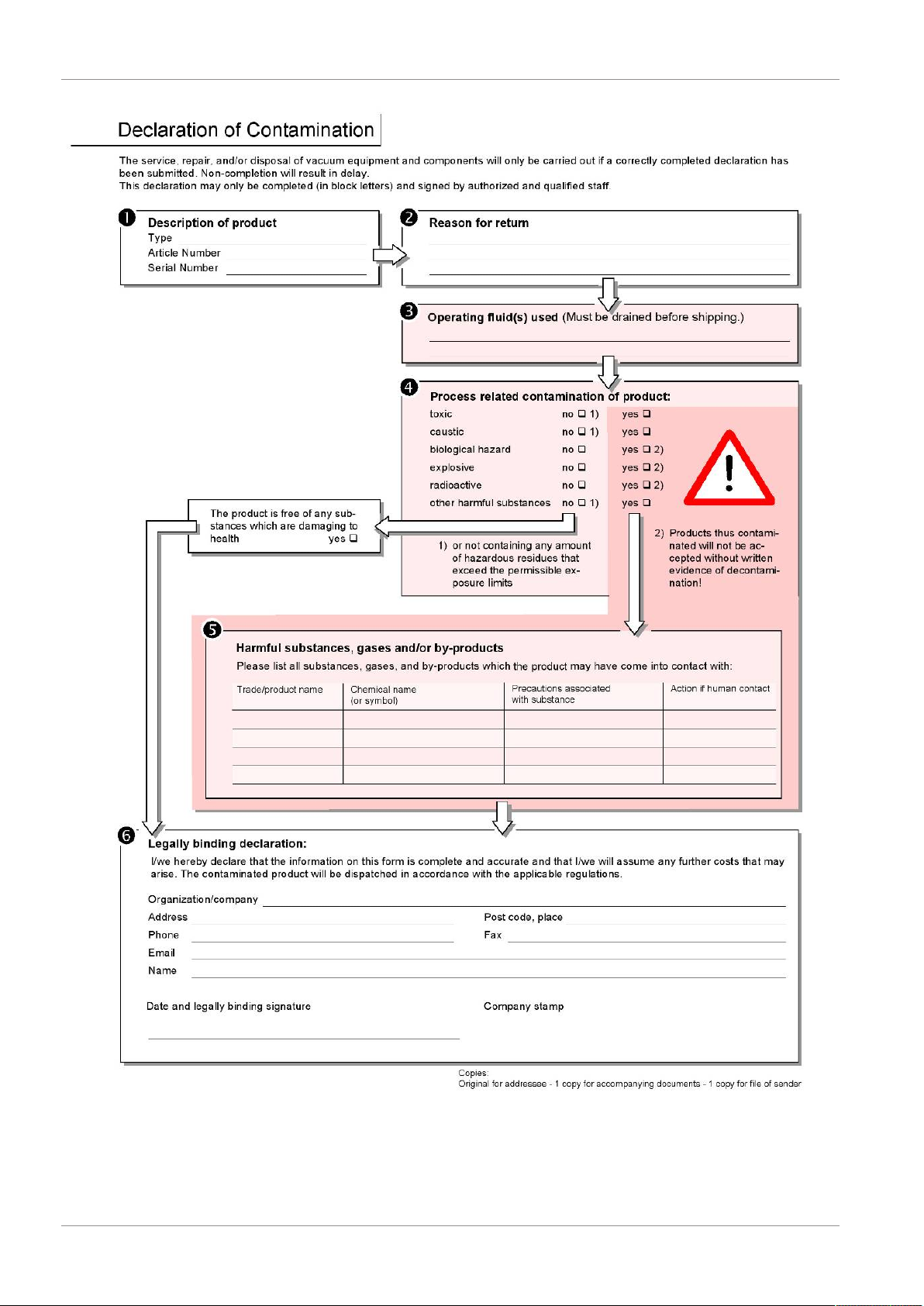
7.2 Sending in the device
WARNING
Danger due to harmful substances
Contaminated devices could endanger the health. The contamination declaration
serves to protect all persons who come into contact with the device.
► Fill in the declaration of contamination completely.
1
Please do not hesitate to contact us and send a completed declaration of
contamination before sending anything to us.
ð You will then receive a return number from us.
2
Use the original packaging when returning.
3
Before sending the device, attach a copy of the completed contamination
declaration. See below.
CU1000-operating-instructions-jina54en1-06-(1901) 29 / 36
Page 30
7 | Decommissioning the measuring instrument INFICON
30 / 36 CU1000-operating-instructions-jina54en1-06-(1901)
Page 31

INFICON Appendix | 8
8 Appendix
8.1 CE Declaration of Conformity
CU1000-operating-instructions-jina54en1-06-(1901) 31 / 36
Page 32

8 | Appendix INFICON
8.2 RoHS
32 / 36 CU1000-operating-instructions-jina54en1-06-(1901)
Page 33

INFICON Appendix | 8
CU1000-operating-instructions-jina54en1-06-(1901) 33 / 36
Page 34

8 | Appendix INFICON
34 / 36 CU1000-operating-instructions-jina54en1-06-(1901)
Page 35

Page 36

 Loading...