

Page 1
OPERATING MANUAL
Crystal12
Sensor
IPN 074-398-P1
™
Page 2

Page 3

OPERATING MANUAL
Crystal12
Sensor
IPN 074-398-P1A
™
Page 4

Trademarks
The trademarks of the products mentioned in this Operating Manual are held by the companies that
produce them.
INFICON®, Crystal12™, and Composer® are trademarks of INFICON Inc.
ConFlat® is a registered trademark of Varian Associates.
Teflon® is a registered trademark of Dupont.
Scotch-Brite™ is a trademark of 3M.
SWAGELOK® and CAJON® are registered trademarks of Swagelok, Co.
Inconel® is a registered trademark of International Nickel Co.
Microdot® is a registered trademark of Microdot Corp.
All other brand and product names are trademarks or registered trademarks of their respective companies.
The information contained in this Operating Manual is believed to be accurate and reliable. However, INFICON
assumes no responsibility for its use and shall not be liable for any special, incidental, or consequential
damages related to the use of this product.
All rights reserved. Reproduction or adaptation of any part of this document without permission is unlawful.
© 2004 INFICON
Page 5

Registration Card
Thank you for selecting INFICON instrumentation.
®
Please fill out and return this postage paid card as soon as possible.
Model
Serial #
Name
Title
Company
Address
City
Country
State Zip
Fax# Email
Bldg./MS
Phone #
Your help is very important in our continuing efforts to improve our manuals.
Using the table below, please circle the appropriate rank for each aspect.
In the Importance column, please indicate the importance of each aspect.
Manual Title
Very
VD
VD
074-
Dissatisfied
D
D
No
Opinion
NO
NO
Satisfied
S
S
Very
Satisfied
VS
VS
(ranked from
1 to 5, where
1 is low and
Part # (see Title Page)
Aspect
Found everything
I needed
Easy to read
Dissatisfied
Importance
5 is high)
Easy to use
Relevant to
my work
Accurate
information
Well-written
Well-organized
Technical Enough
Helped me
solve problems
VD
VD
VD
VD
VD
VD
VD
D
D
D
D
D
D
D
NO
NO
NO
NO
NO
NO
NO
S
S
S
S
S
S
If you have additional comments, please contact INFICON.
GLOBAL HEADQUARTERS:
Two Technology Place, East Syracuse, NY 13057 USA
Tel: +1.315.434.1100 Fax: +1.315.437.3803 E-mail: reachus@inficon.com
Visit us on the web at:
©2004 INFICON
www.inficon.com
VS
S
VS
VS
VS
VS
VS
VS
®
Page 6
BUSINESS REPLY MAIL
FIRST CLASS PERMIT NO. 49 EAST SYRACUSE, NEW YORK
POSTAGE WILL BE PAID BY ADDRESSEE
INFICON INC.
Two Technology Place
East Syracuse, New York 13057-9714
Page 7

Warranty
WARRANTY AND LIABILITY - LIMITATION: Seller warrants the products
manufactured by it, or by an affiliated company and sold by it, and described on
the reverse hereof, to be, for the period of warranty coverage specified below, free
from defects of materials or workmanship under normal proper use and service.
The period of warranty coverage is specified for the respective products in the
respective Seller instruction manuals for those products but shall not be less than
one (1) year from the date of shipment thereof by Seller. Seller's liability under this
warranty is limited to such of the above products or parts thereof as are returned,
transportation prepaid, to Seller's plant, not later than thirty (30) days after the
expiration of the period of warranty coverage in respect thereof and are found by
Seller's examination to have failed to function properly because of defective
workmanship or materials and not because of improper installation or misuse and
is limited to, at Seller's election, either (a) repairing and returning the product or
part thereof, or (b) furnishing a replacement product or part thereof, transportation
prepaid by Seller in either case. In the event Buyer discovers or learns that a
product does not conform to warranty, Buyer shall immediately notify Seller in
writing of such non-conformity, specifying in reasonable detail the nature of such
non-conformity. If Seller is not provided with such written notification, Seller shall
not be liable for any further damages which could have been avoided if Seller had
been provided with immediate written notification.
THIS WARRANTY IS MADE AND ACCEPTED IN LIEU OF ALL OTHER
WARRANTIES, EXPR ESS OR IMP LIED, WHETH ER OF MERCHANTABILITY OR
OF FITNESS FOR A PARTICULAR PURPOSE OR OTHERWISE, AS BUYER'S
EXCLUSIVE REMEDY FOR ANY DEFECTS IN THE PRODUCTS TO BE SOLD
HEREUNDER. All other obligations and liabilities of Seller, whether in contract or
tort (including negligence) or otherwise, are expressly EXCLUDED. In no event
shall Seller be liable for any costs, expenses or damages, whether direct or
indirect, special, incidental, consequential, or other, on any claim of any defective
product, in excess of the price paid by Buyer for the product plus return
transportation charges prepaid.
No warranty is made by Seller of any Seller product which has been installed,
used or operated contrary to Seller's written instruction manual or which has been
subjected to misuse, negligence or accident or has been repaired or altered by
anyone other than Seller or which has been used in a manner or for a purpose for
which the Seller product was not designed nor against any defects due to plans or
instructions supplied to Seller by or for Buyer.
This manual is intended for private use by INFICON® Inc. and its customers.
Contact INFICON before reproducing its contents.
NOTE: These instructions do not provide for every contingency that may arise in
connection with the installation, operation or maintenance of this equipment.
Should you require further assistance, please contact INFICON.
GLOBAL HEADQUARTERS:
Two Technology Place, East Syracuse, NY 13057 USA
Tel: +1.315.434.1100 Fax: +1.315.437.3803 E-mail: reachus@inficon.com
Visit us on the web at:
©2004 INFICON
www.inficon.com
Page 8

Page 9

Contact List
For Customer Support, contact the INFICON office nearest to you.
Customer Support information is also available at www.inficon.com.
North America
USA — East Syracuse, NY
Phone: +1.315.434.1100
Fax: +1.315.437.3803
Email: service.usa@inficon.com
USA — Santa Clara, CA
Phone: +1.408.361.1200
Fax: +1.408.362.1556
Email: service.usa@inficon.com
USA — Austin, TX
Phone: +1.512.448.0488
Fax: +1.512.448.0398
Email: service.usa@inficon.com
Europe
Germany — Koeln
Phone: +49.221.347.42222
Fax: +49.221.347.42221
Email: leakdetection.service@inficon.com
Principality of Liechtenstein — Balzers
Phone: +423.388.3111
Fax: +423.388.3700
Email: service.europe@inficon.com
Asia / Pacific
China — Beijing
Phone: +86.10.6590.0164
Fax: +86.10.6590.0521
Email: reach.china@inficon.com
China — Guangzhou
Phone: +86.20.8723.6963
Fax: +86.20.8723.6003
Email: reach.china@inficon.com
China — Hong Kong
Phone: +852.2520.2880
Fax: +852.2865.6883
Email: reach.china@inficon.com
China — Shanghai
Phone: +86.21.6209.3094
Fax: +86.21.6295.2852
Email: reach.china@inficon.com
Japan — Yokohama
Phone: +81.45.471.3328
Fax: +81.45.471.3327
Email: reach.japan@inficon.com
Korea — Suwon
Phone: +82.31.708.2891
Fax: +82.31.708.3056
Email: reach.korea@inficon.com
Singapore
Phone: +65.890.6250
Fax: +65.890.6266
Email: reach.singapore@inficon.com
T aiwan — HsinChu
Phone: +886.3.552.5828
Fax: +886.3.552.5829
Email: reach.taiwan@inficon.com
Middle East / Africa
Israel
Phone: +972.3.534.6822
Fax: +972.3.534.2589
South Africa
Phone: +27.11.793.6831
Fax: +27.11.793.7172
Turkey
Phone: +90.216.327.4041
Fax: +90.216.327.4046
Latin America
Argentina
Phone: +54.11.4701.6200
Fax: +54.11.4702.2546
Bolivia
Phone: +59.12.32.2198
Fax: +59.12.32.9751
Brazil
Phone: +55.11.41544888
Fax: +55.11.41544888
Email: pv@prestvacuo.com.br
Chile
Phone: +56.2.235.9686
Fax: +56.2.235.1680
Columbia
Phone: +57.1.335.1100
Fax: +57.1.269.6923
Email: reciend@colomsat.net.co
Ecuador
Phone: +59.32.22.7174
Fax: +59.32.50.2996
Mexico
Phone: +52.5.752.6746
Fax: +52.5.754.8664
Email: meisaventas@infosel.net.mx
Peru
Phone: +51.14.51.8947
Fax: +51.14.64.1820
Venezuela
Phone: +58.2.944.2010
Fax: +58.2.944.3123
Page 10

Page 11

Crystal12 Sensor Operating Manual
T able Of Contents
Chapter 1
Sensor Specifications
1.1 Specifications for Crystal12 Sensor 750-667-G1 . . . . . . . . . . . . . . . . . . . . .1-1
1.1.1 Installation Requirements. . . . . . . . . . . . . . . . . . . . . . . . . . . . . . . . . . . . . . .1-2
1.1.1.1 Feedthrough. . . . . . . . . . . . . . . . . . . . . . . . . . . . . . . . . . . . . . . . . . . . . . . . .1-2
1.1.1.2 Other. . . . . . . . . . . . . . . . . . . . . . . . . . . . . . . . . . . . . . . . . . . . . . . . . . . . . . .1-2
1.1.1.3 Utilities . . . . . . . . . . . . . . . . . . . . . . . . . . . . . . . . . . . . . . . . . . . . . . . . . . . . .1-2
1.1.2 Materials. . . . . . . . . . . . . . . . . . . . . . . . . . . . . . . . . . . . . . . . . . . . . . . . . . . .1-3
1.1.3 Unpacking Instructions. . . . . . . . . . . . . . . . . . . . . . . . . . . . . . . . . . . . . . . . .1-3
1.1.4 Inventory. . . . . . . . . . . . . . . . . . . . . . . . . . . . . . . . . . . . . . . . . . . . . . . . . . . .1-4
1.1.4.1 Standard. . . . . . . . . . . . . . . . . . . . . . . . . . . . . . . . . . . . . . . . . . . . . . . . . . . .1-4
1.1.4.2 Options. . . . . . . . . . . . . . . . . . . . . . . . . . . . . . . . . . . . . . . . . . . . . . . . . . . . .1-4
1.2 Using this Manual. . . . . . . . . . . . . . . . . . . . . . . . . . . . . . . . . . . . . . . . . . . .1-12
1.2.1 Symbols and their Definitions. . . . . . . . . . . . . . . . . . . . . . . . . . . . . . . . . . .1-12
1.3 How to Contact Customer Support. . . . . . . . . . . . . . . . . . . . . . . . . . . . . . .1-13
1.3.1 Returning Your Crystal12 Sensor to INFICON. . . . . . . . . . . . . . . . . . . . . .1-13
Chapter 2
Sensor Installation
2.1 Crystals in the Crystal12 Sensor . . . . . . . . . . . . . . . . . . . . . . . . . . . . . . . . .2-1
2.1.1 Handle the Crystal with Care . . . . . . . . . . . . . . . . . . . . . . . . . . . . . . . . . . . .2-1
2.1.2 Replacing Crystals . . . . . . . . . . . . . . . . . . . . . . . . . . . . . . . . . . . . . . . . . . . .2-1
2.2 Pre-installation Sensor Check . . . . . . . . . . . . . . . . . . . . . . . . . . . . . . . . . . .2-2
2.2.1 Cygnus Deposition Controller. . . . . . . . . . . . . . . . . . . . . . . . . . . . . . . . . . . .2-3
2.3 General Guidelines for Crystal12 Sensor. . . . . . . . . . . . . . . . . . . . . . . . . . .2-3
IPN 074-398-P1A
2.3.1 Crystal Sensor Installation . . . . . . . . . . . . . . . . . . . . . . . . . . . . . . . . . . . . . .2-5
2.4 Crystal12 Sensor Installation when used with Cygnus. . . . . . . . . . . . . . . . .2-7
2.4.1 Changing Crystal Sensor Type and
Programming the Relay Outputs . . . . . . . . . . . . . . . . . . . . . . . . . . . . . . . . .2-7
2.4.2 Wiring the Relay Outputs with Relay I/O Boards
760-162-G1 or 760-162-G1/G2 . . . . . . . . . . . . . . . . . . . . . . . . . . . . . . . . . .2-9
2.5 Crystal12 Operation when used with a Cygnus . . . . . . . . . . . . . . . . . . . . .2-11
2.5.1 Initialization. . . . . . . . . . . . . . . . . . . . . . . . . . . . . . . . . . . . . . . . . . . . . . . . .2-11
2.5.2 Crystal Switching . . . . . . . . . . . . . . . . . . . . . . . . . . . . . . . . . . . . . . . . . . . .2-11
2.6 Crystal12 Sensor Requirement when Not Installed with a Cygnus . . . . . .2-12
TOC - 1
Page 12

Crystal12 Sensor Operating Manual
Chapter 3
Installation of the Solenoid Valve Assembly
3.1 Installation with 1” Bolts . . . . . . . . . . . . . . . . . . . . . . . . . . . . . . . . . . . . . . . .3-1
3.2 Installation with 2 3/4” Feedthrough. . . . . . . . . . . . . . . . . . . . . . . . . . . . . . .3-2
3.3 Electrical and Pneumatic Connections. . . . . . . . . . . . . . . . . . . . . . . . . . . . . 3-3
3.3.1 Electrical. . . . . . . . . . . . . . . . . . . . . . . . . . . . . . . . . . . . . . . . . . . . . . . . . . . .3-3
3.3.2 Pneumatic Solenoid Tube Connections. . . . . . . . . . . . . . . . . . . . . . . . . . . .3-3
Chapter 4
Maintenance
4.1 General Precautions. . . . . . . . . . . . . . . . . . . . . . . . . . . . . . . . . . . . . . . . . . .4-1
4.1.1 Maintain the Temperature of the Crystal . . . . . . . . . . . . . . . . . . . . . . . . . . .4-1
4.1.2 Use the Optimum Crystal Type . . . . . . . . . . . . . . . . . . . . . . . . . . . . . . . . . .4-1
4.1.3 Crystal Concerns when Opening the Chamber . . . . . . . . . . . . . . . . . . . . . . 4-1
4.2 Crystal Seat Maintenance . . . . . . . . . . . . . . . . . . . . . . . . . . . . . . . . . . . . . .4-2
4.3 Alignment Instruction for Crystal12 Sensor (IPN 750-667) . . . . . . . . . . . . .4-2
4.3.1 Required Equipment. . . . . . . . . . . . . . . . . . . . . . . . . . . . . . . . . . . . . . . . . . .4-2
4.3.2 Procedure. . . . . . . . . . . . . . . . . . . . . . . . . . . . . . . . . . . . . . . . . . . . . . . . . . .4-3
4.3.3 Replacing the Bellows Assembly (750-286-P2). . . . . . . . . . . . . . . . . . . . . .4-6
4.3.3.1 Equipment required:. . . . . . . . . . . . . . . . . . . . . . . . . . . . . . . . . . . . . . . . . . .4-6
4.3.3.2 Procedure. . . . . . . . . . . . . . . . . . . . . . . . . . . . . . . . . . . . . . . . . . . . . . . . . . .4-6
4.3.4 Replacing the Electrical Connection Assembly . . . . . . . . . . . . . . . . . . . . . . 4-7
4.3.4.1 Equipment Required. . . . . . . . . . . . . . . . . . . . . . . . . . . . . . . . . . . . . . . . . . .4-7
4.3.4.2 Procedure. . . . . . . . . . . . . . . . . . . . . . . . . . . . . . . . . . . . . . . . . . . . . . . . . . .4-7
4.4 Cygnus Status and Error Messages. . . . . . . . . . . . . . . . . . . . . . . . . . . . . . .4-8
4.5 Troubleshooting the Crystal12 Sensor. . . . . . . . . . . . . . . . . . . . . . . . . . . . . 4-8
Chapter 5
Feedthrough Outline Drawings
IPN 074-398-P1A
TOC - 2
Page 13
Crystal12 Sensor Operating Manual
Sensor Specifications
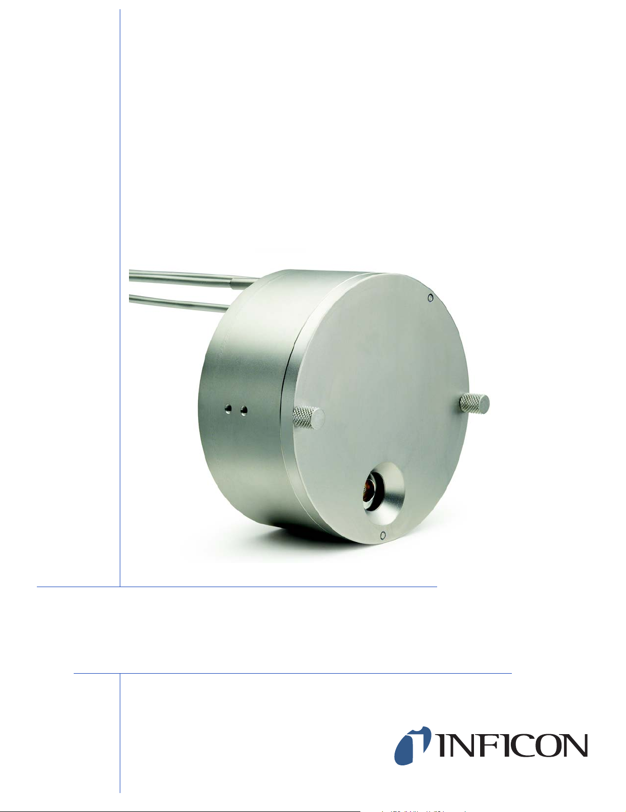
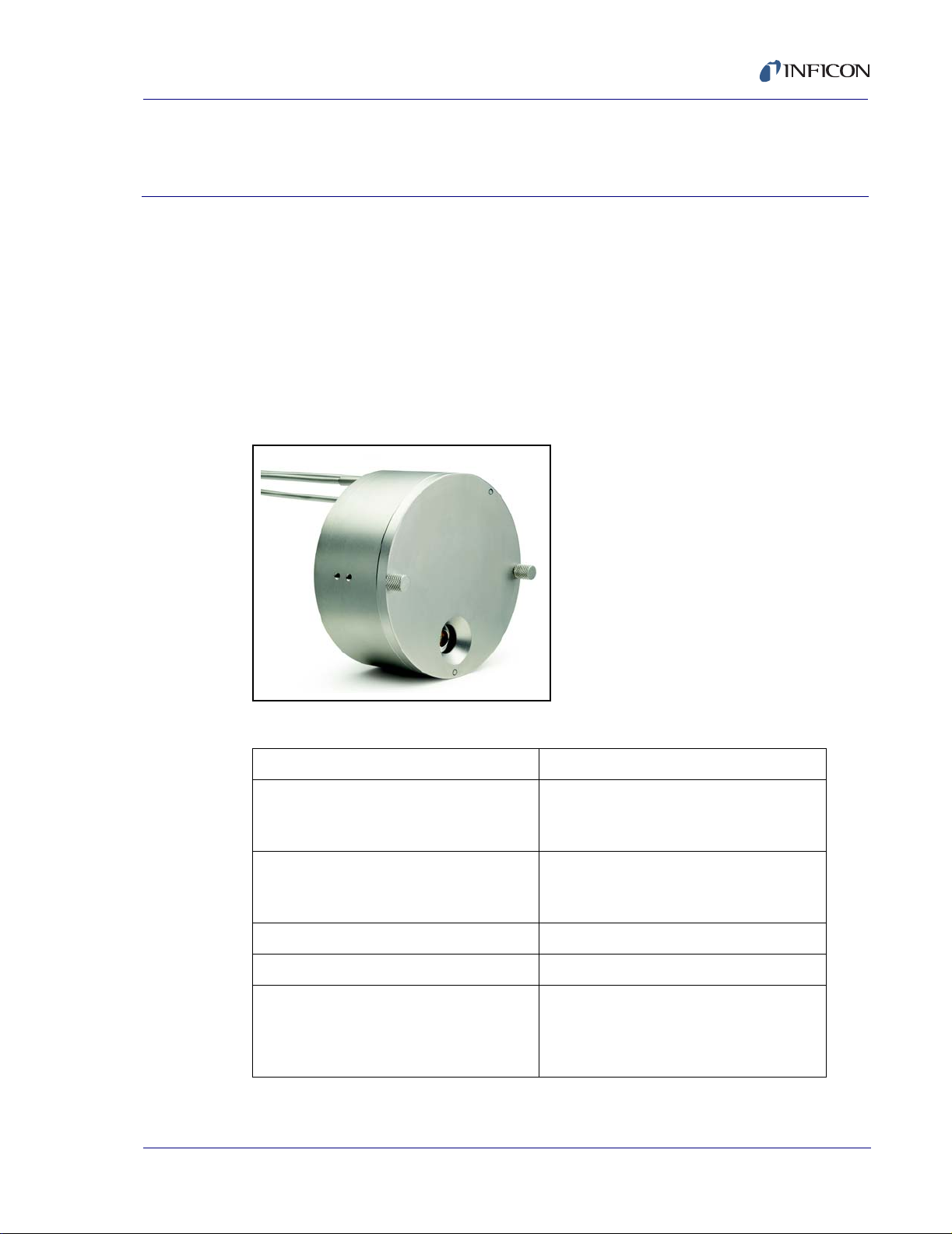
1.1 Specifications for Crystal12 Sensor 750-667-G1
The Crystal12 sensor is a twelve crystal quartz crystal deposition monitor
transducer. When the monitor crystal being used fails, a new crystal is advanced
into position, fully replacing the failed crystal’s function. The mechanism used for
providing this motion is pneumatically powered. The logic for automatic operation
of this transducer is provided with the Cygnus™ Deposition Controller.
See Figure 1-1 and Table 1-1.
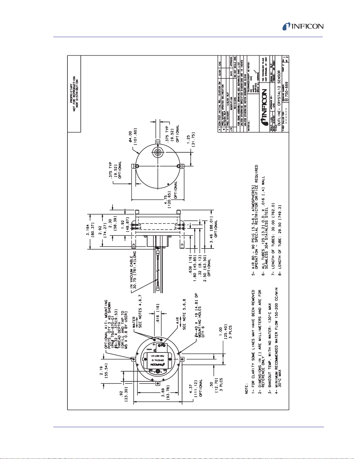
Figure 1-1 Crystal12 Sensor
Chapter 1
074-398-P1A
Table 1-1 Sensor Specification
Maximum bakeout temp with no water 130 °C
Maximum operating isothermal
environment temperature with minimum
water flow
Size (maximum envelope) 4.0" (102 mm) dia. x 3.3" (84 mm) high
Water, air and coax length Standard 30" (762 mm)
Crystal exchange Front-loading
Mounting Six #4-40 tapped holes on the back of the
300 °C
4.75" (121 mm) dia. x 3.46" (88 mm) with
optional mounting posts installed
sensor body, six #4-40 tapped holes on
outside circumference. Three #6-32
tapped holes with optional mounting kit.
1 - 1
Page 14
Crystal12 Sensor Operating Manual
1.1.1 Installation Requirements
1.1.1.1 Feedthrough
Qty (1) 2-3/4" ConFlat® with two coaxial feedthroughs, two p ass water, one air
IPN 002-080, See Figure 5-2 on page 5-2 or,
Qty (1) 1" bolt with 1 coaxial feedthrough, two pass water, one air IPN
750-030-G1, see Figure 5-1 on page 5-1.
1.1.1.2 Other
User to provide mounting structure adequate to support weight of Crystal12
and designed to facilitate removal and replacement with minimal change in
exact position. An optional mounting post kit, IPN 750-670-G1, may be
purchased for this purpose.
CAUTION
Do not mount the Crystal12 unsupported.
1.1.1.3 Utilities
User to provide vacuum-tight braze joints or connectors for the water and air
tubes.
V alve assembly for air, IPN 750-420-G1 (not provided), with a 0.022" restrictor
orifice installed by the user . (Orifice included with Crystal12 accessory kit.) See
Table 1-3 on page 1-4.
XIU or Oscillator designed to interface with the Cygnus controller.
Minimum water flow 150-200 cc/min, 30 °C max (Do not allow water to freeze).
Coolant should not contain chlorides as stress corrosion cracking may occur.
Regulated air supply 80-90 PSIG (5.5 bar - 6.2 bar) [550 kPa - 620 kPa]
074-398-P1A
2 meter maximum length of 1/8" tubing between bellows assembly and the
control valve.
CAUTION
Do not allow water tubes to freeze. This may happen if the
tubes pass through a cryogenic shroud and the fluid’s
flow is interrupted.
1 - 2
Page 15

1.1.2 Materials
Table 1-2 Materials
Crystal12 Sensor Operating Manual
Plate, Material Shield, Mechanical Parts,
Body and Carousel
Springs, Electrical Contacts Au plated Be-Cu, Au Plate 302 stainless
Water and air tubes S-304, 0.125" (3.2 mm) O.D. x .016"
Connector Stain less steel
Insulators Teflon®, Peek®
Cable Teflon insulated copper plated steel
Crystal 0.550" (13.97 mm) Diameter
1.1.3 Unpacking Instructions
The Crystal12 sensor and accessories are p ackaged in a single cardboard carton
with rigid foam inserts.
Carefully remove the packaged accessories before removing the sensor.
The unit in the shipped condition has been aligned at the factory, no further
alignment is required.
304 type stainless steel
steel
(0.4 mm) Wall Thickness x 30" Lo ng (762
mm) Seamless Stainless Steel Tubing
074-398-P1A
During shipment, units may vibrate slightly out of position. This does not mean
alignment is required. The unit will return to the centered position the first time it is
pneumatically activated.
1 - 3
Page 16

Crystal12 Sensor Operating Manual
1.1.4 Inventory
1.1.4.1 Standard
In addition to the basic transducer, the complete shipping package includes an
accessory kit (IPN 750-268-G3) which consists of the following:
Table 1-3 Contents of Accessory Kit
Qty IPN Description
X 750-268-G3 Accessory Kit, Crystal12 Sensor
1 750-254-G2 Assembly, Alignment Tool
1 074-5000 CD, Thin Film Manuals
2 008-010-G10 Sensor Crystal 6 MHz (10 crystals per package)
1 059-189 CC-1010-0225 Orifice 0.0225" diameter
2 070-201 #4 Split Lock Washer, Stainless Steel
2 084-032 #4-40x0.375" Long Socket Head Cap Screw, Stainless Steel
2 084-039 #4-40x0.500" Long Socket Head Cap Screw, Stainless Steel
1.1.4.2 Options
Table 1-4 Options
2 084-084 #4-40x0.688" Long Socket Head Cap Screw, Stainless Steel
1 070-828 Hex Wrench 1/16" SC9-3
1 070-829 Hex Wrench 3/32" SC9-5
1 070-1175 Hex Wrench 5/64" SC9-4
1 750-037-G1 Spring Tube Bender Kit
1 750-191-G1 Molybdenum Disulfide in Alcohol
Qty IPN Description
074-398-P1A
1 750-670-G1 Mounting Post Kit
1 750-420-G1 3-Way Solenoid Valve Assembly
1 - 4
Page 17
Crystal12 Sensor Operating Manual
074-398-P1A
Figure 1-2 Outline of Crystal12 Sensor - Page 1 of 2
1 - 5
Page 18
Crystal12 Sensor Operating Manual
1 - 6
Figure 1-3 Outline of Crystal12 Sensor - Page 2 of 2
074-398-P1A
Page 19

Crystal12 Sensor Operating Manual
074-398-P1A
Figure 1-4 Assembly Crystal12 Sensor - Page 1 of 4
1 - 7
Page 20

Crystal12 Sensor Operating Manual
1 - 8
Figure 1-5 Assembly Crystal12 Sensor - Page 2 of 4
074-398-P1A
Page 21

Crystal12 Sensor Operating Manual
074-398-P1A
Figure 1-6 Assembly Crystal12 Sensor - Page 3 of 4
1 - 9
Page 22

Crystal12 Sensor Operating Manual
1 - 10
Figure 1-7 Assembly Crystal12 Sensor - Page 4 of 4
074-398-P1A
Page 23

Figure 1-8 Crystal Carousel
Crystal12 Sensor Operating Manual
4
Locating Hole
3
Alignment Hole
2
6 MHz Crystals
074-398-P1A
1
Pin
1 - 11
Page 24

Crystal12 Sensor Operating Manual
1.2 Using this Manual
Please take a moment to read the following.
1.2.1 Symbols and their Definitions
NOTE: Notes provide additional information about the current topic.
HINT: Hints provide insight into product usage.
CAUTION
This caution paragraph cautions against actions which
may bring about a malfunction or the loss of data.
WARNING
This warning paragraph warns of actions that may result
in physical injury to the user.
WARNING - Risk Of Electric Shock
This warning paragraph warns of potentially lethal
voltages.
074-398-P1A
1 - 12
Page 25

Crystal12 Sensor Operating Manual
1.3 How to Contact Customer Support
If you need assistance with your sensor , please read this Operating Manual bef ore
contacting Customer Support. If you can not find the answer in this manual, decide
whether:
Your sensor functions, but it does not work for your application — request
Application Assistance.
Y our sensor functions, but you need to know ho w to use it — request Technical
Support.
Your sensor does not function (it’s broken) — request Repair Services.
You need to order parts — request Order Services.
When you contact Customer Support, please have the following information readily
available:
The Lot Identification Code for your sensor. For the location of the Lot
Identification Code, refer to Figure 1-4 on page 1-7.
A description of your problem.
074-398-P1A
An explanation of any corrective action that you may have already attempted.
The exact wording of any error messages that you have received.
To contact Customer Support. refer to the contact list located at the front of this
manual. Or, contact your sales office. Or, see the www.inficon.com website.
1.3.1 Returning Your Crystal12 Sensor to INFICON
Do not return any component of your sensor to INFICON without first speaking with
a Customer Support Representative. You must obtain a Return Material
Authorization (RMA) number from the Customer Support Representative.
If you deliver a package to INFICON without an RMA number , your package will be
held and you will be contacted. This will result in delays in servicing your sensor.
Prior to being given an RMA number , you will be required to complete a Declaration
Of Contamination (DOC) form if your sensor has been exposed to process
materials. DOC forms must be approved by INFICON before an RMA number is
issued. INFICON may require that the sensor be sent to a designated
decontamination facility, not to the factory. Failure to follow these procedures will
delay the repair of your sensor.
1 - 13
Page 26

Crystal12 Sensor Operating Manual
This page is intentionally blank.
1 - 14
074-398-P1A
Page 27

Crystal12 Sensor Operating Manual
Successful operation of any crystal sensor depends on proper placement,
compatibility of its construction with its operating environment and connection to
proper utilities.
NOTE: The sensor head, water tubes, cable, etc. should be clean and grease free
when installed in the vacuum chamber. These parts should be handled
while wearing clean nylon gloves. If parts do become conta minated, clean
them thoroughly using a suitable solvent to avoid outgassing and
excessive peeling of deposition material from the sensor’s surfaces.
2.1 Crystals in the Crystal12 Sensor
2.1.1 Handle the Crystal with Care
Always use clean nylon lab gloves and clean nylon or Teflon tweezers when
handling the crystal. Handle the crystals only by their edges. Anything that comes
in contact with the crystal surfaces may leave contamination, which may lead to
poor film adhesion. Poor film adhesion will result in high rate noise and prematur e
crystal failure.
Chapter 2
Sensor Installation
074-398-P1A
CAUTION
Do not use metal tweezers to handle crystals. Metal
tweezers may chip the edge of the crystal and lead to
short life, erratic resonance, or both.
2.1.2 Replacing Crystals
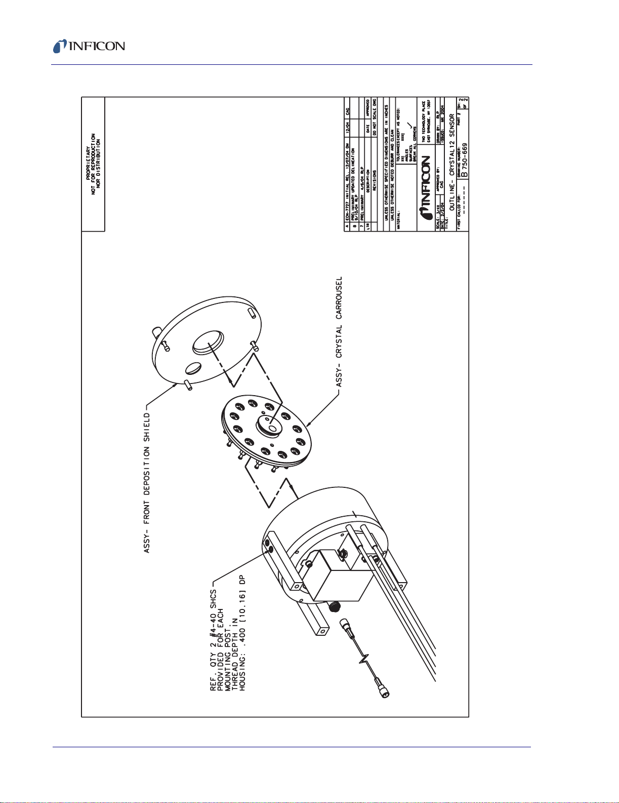
Replacing crystals in the Crystal12 requires removal of the front deposition shield
(item 17, Figure 1-5 on page 1-8). This is accomplished by removing the two
captive fasteners that attach the front deposition shield to the carousel housing
(item 14, Figure 1-5 on page 1-8).
The crystal carousel (item 15, Figure 1-5 on page 1-8) is removed from the
carousel housing by gripping the carousel assembly by the protruding hub and
applying pressure using your index finger near the radial edge of the carousel.
The Cygnus detects when a carousel is removed and displays a "Carousel
Change-Out" message. When a carousel change-out occurs, all crystals are
identified as failed with a message displayed on the channel pages. Crystal
2 - 1
Page 28

Crystal12 Sensor Operating Manual
position 12 is displayed as the assumed current position until the change-out is
complete and a rotate head or crystal switch function is performed. At the end of
the rotate head function, the sensor will be at position number 1.
Replacement of the twelve monitor crystals requires the removal of the two
fasteners (item 4, Figure 1-8 on page 1-11) that secure the two halves (items 1 and
3) of the assembly.
Exchanging the crystals is accomplished by inverting the plate (item 1, Figure 1-8
on page 1-11) containing the used crysta ls and in stalling th e new cryst als (item 2)
in the orientation shown in Figure 1-8 on page 1-11.
Reassemble the crystal carousel assembly by orientating the pin protruding from
item 1 (refer to Figure 1-8 on page 1-11) with the hole provided in item 3, then
securing the two halves with fasteners (item 4).
To install the carousel assembly into the Crystal12 sensor, grasp the carousel
assembly by the protruding hub and orient the locating hole of the carousel
assembly (item 15, Figure 1-5 on page 1-8) with the #6-32 location screw (item 21 ,
Figure 1-5 on page 1-8). The carousel assembly should snap into place.
Orient and attach the front deposition shield (item 17, Figure 1-5 on page 1-8) to
the carousel housing (item 14, Figure 1-5 on page 1-8) using the two knurled
captive fasteners.
The crystal status and "Carousel Change-Out" message on the Cygnus display will
remain unchanged subsequent to a carousel replacement until one of the following
occurs.
A "Rotate Head" function is initiated via remote communications, or from the
front display soft key of either the ALL CHANNELS MAINTENANCE display or
the individual CHANNEL SENSOR MAINTENANCE display. This is the
preferred method because it ensures the correct position is detected while
providing an accurate accounting of good and failed crystals.
A crystal switch function via the front display "soft key", hand held controller or
remote communication is initiated.
The user manually rotates the carousel to make electrical contact.
When the Cygnus detects a crystal position, the "Carousel Change-Out" message
is removed and all crystals are labeled as good.
2.2 Pre-installation Sensor Check
Prior to installing the sensor in the vacuum system, you should make certain it is in
proper working condition by following the procedure outlined below.
074-398-P1A
2 - 2
Page 29

2.2.1 Cygnus Deposition Controller
1 Connect the in-vacuum sensor head cable to the feedthrough or a coax adapter
(Microdot/BNC).
2 Connect one end of the 6" XIU cable (IPN 755-257-G6) to the BNC connector
of the feedthrough.
3 Connect the other end of the 6" XIU cable to the connector of the XIU (IPN
760-600-G1).
4 Connect one end of the XIU cable (IPN 600-1039-Gxx) to the mating connector
of the XIU.
5 Connect the other end of the XIU cable to a sensor channel at the rear of the
controller.
6 Connect power to the controller and set the power switch to ON. The instru ment
will power up in the ALL CHANNELS display.
If the RATE field corresponding to the sensor channel selected in the
previous step is displayed in normal video and is actively being updated,
you can assume the sensor is in proper working order and may be installed.
Crystal12 Sensor Operating Manual
074-398-P1A
If the RATE field is displayed in inverse video, a failed crystal condition
exists for the specific channel. The carousel assembly (item 1 5, Figure 1-5
on page 1-8) may have to be manually advanced by hand to make an
electrical contact to correct the failed condition.
NOTE: The carousel assembly may also be advanced by temporarily
connecting a regulated air supply (80-90 PSIG (5.5 bar - 6.2 bar)
[550 kPa - 620 kPa]) to the tube of the bellows assembly (item 37,
Figure 1-5 on page 1-8).
2.3 General Guidelines for Crystal12 Sensor
Figure 2-1 shows the typical installation of an INFICON water-cooled crystal sensor
in the vacuum process chamber. Refer to Chapter 3 for information regarding the
installation of the solenoid valve assembly (750-420-G1) used to pneumatically
index the sensor. Use the illustration and the following guidelines to install your
sensor(s) for optimum performance and convenience.
2 - 3
Page 30

Crystal12 Sensor Operating Manual
Figure 2-1 Typical Cystal12 Installation for Cygnus
Crystal12
IPN 750-667-G1
CYGNUS
AIR 80-90 PSIG
IPN 750-420-G1
CHANNEL 1 or 2 (STANDARD)
074-398-P1A
2 - 4
Page 31

2.3.1 Crystal Sensor Installation
Generally, install the sensor as far as possible from the evaporation source (a
minimum of 10" or 25.4 cm) while still being in a position to accumulate thickness
at a rate proportional to accumulation on the substrate. Figure 2-2 shows proper
and improper sensor positioning.
Figure 2-2 Sensor Installation Guidelines
Crystal12 Sensor Operating Manual
Correct
Incorrect
Obstruction
074-398-P1A
Incorrect
Incorrect
Source
Correct
To guard against spattering, use a source shutter to shield the sensor during the
initial soak periods. If the crystal is hit with even a minute particle of molten
material, it may be damaged and stop oscillating. Even in cases when it does not
completely stop oscillating, it may immediately become unstable, or shortly after
deposition begins instability may occur.
Plan the installation to insure that there are no obstructions blocking a direct path
between the sensor and the source.
Install sensors in such a manner that the center axis of the crystal is aimed directly
at the source to be monitored. Verify that the angle of the sensor location (with
reference to the source) is well within the evaporant stream.
Attach the sensor with a mounting bracket anchored to the deposition chamber.
With the bracket in place, temporarily position and attach the sensor head as
outlined in the general guidelines above. Next, temporarily install the feedthrough.
You may now form, measure, and mark the sensor’s tubes (use the bending tool
(IPN 750-036) to form tubes in the system).
2 - 5
Page 32

Crystal12 Sensor Operating Manual
Build the Sensor/Feedthrough Assembly . Remove the sensor and the feed through,
cut the water cooling tubes and air tubes to the proper length and connect them
directly to the feedthrough or use vacuum rated couplings.
CAUTION
To prevent damage to the feedthrough or sensor during
welding or brazing, insure that at least one inch of water
tube is left between the sensor and the feedthrough.
After cutting the water and air tubes, verify that they are clear of met al p articles by
forcing compressed air through the tubing. Heliarc welding is recommended (torch
brazing may also be acceptable) for connecting the sensor to the feedthrough
water tube.
Vacuum rated connectors such as CAJON® are recommended for use between
the sensor and the feedthrough to speed maintenance. If brazing adapters are to
be used, attach them to the sensor water-cooling tubes prior to connection to the
feedthrough. Make connections as follows:
1 Clean the water tube and adapter surfaces with solvent if necessary.
2 Apply brazing flux to surfaces being joined.
3 Braze the connections using a flame temperature appropriate for the brazing
material being used.
CAUTION
Excessive application of brazing material, or excessive
heat due to brazing, may result in blockage of the water
tube.
4 Verify that each joint is not blocked by blowing compressed air through the
cooling tubes.
5 Thoroughly clean the braze joint and helium leak test before installing the
sensor and feedthrough into the process chamber.
Once all water and air tube connections are fabricated, install the sensor and
feedthrough assembly into the process system and secure all retaining ha rdware.
Shield the coax cable from heat radiating from the evaporant source or the
substrate heater . You can do this very simply, if your process allows, by wrapping
aluminum foil around the cable and water tubes. Connect the external water tubes
from the feedthrough to your water supply system and flow controller. We
recommend using detachable couples (Swagelok® or equivalent) for external
water tube connections. Apply water pressure to verify flow and tightness.
074-398-P1A
2 - 6
Page 33

Crystal12 Sensor Operating Manual
Because of geometric factors, variations in surface temperature, and differences in
electrical potential, the crystal and substrates often do not receive the same
amount of material. If you want the thickness indication on the controller to
represent the thickness on the substrates, calibration is required to determine the
tooling. Consult your controller’s manual for the proper procedure for obtaining the
tooling factor.
CAUTION
Use of more than 80" (2 meters) of 1/8" tubing between
the valve and the bellows may cause a switcher failure
because of the time required to bleed out sufficient air
during de-pressurization. If tubing greater than 1/8" is
used, the maximum length must be reduced proportional
to the additional volume.
2.4 Crystal12 Sensor Installation when
074-398-P1A
used with Cygnus
2.4.1 Changing Crystal Sensor Type and Programming the Relay Outputs
1 Display the Hardware # Display (see Figure 2-3).
Figure 2-3 Display Tree for HARDWARE # Display.
ALL CHANNELS Display
F6 CHANNEL
CHANNEL # Display (# designates Channel number selected)
F1 Channel Parms
PROCESS # Display
F1 Hardware Parms
HARDWARE # Display
2 - 7
Page 34

Crystal12 Sensor Operating Manual
2 Select Sensor Type: 1 (Single); 2 (CrystalTwo); 6 (CrystalSix); 12 (Crystal12).
See Figure 2-4.
Figure 2-4 Selecting Sensor Type Example
3 If a Sensor Type 2, 6 or 12 is selected, a Switch Output field appears. Select
the relay output number to be used to activate the crystal switch. See Figure
2-5.
Figure 2-5 Selecting the Output Number Example
074-398-P1A
2 - 8
Page 35

Crystal12 Sensor Operating Manual
2.4.2 Wiring the Relay Outputs with Relay I/O Boards 760-162-G1 or 760-162-G1/G2
On the relay connector , connect the leads of the solenoid valve across the one side
of a 24 volt supply and one side of a relay (1-8, 1-16, or 1-24; whichever was
programmed). See Table 2-1.
Table 2-1 +24 V(dc) Pin Connections
Pin Function
1 Return
2 Return
3 Return
4 Not Connected
5 Not Connected
6+24 Volts
7+24 Volts
074-398-P1A
8+24 Volts
9 Not Connected
CAUTION
Both the isolated 24 V(dc) supply and the RS-232C
remote communications port use a 9-pin D-sub
connector. Care must be taken not to inadvertently
connect the RS-232C remote communications cable to
the 24-volt supply connector. Also, care must be taken
not to inadvertently connect the 24 V(dc) supply cable to
the RS-232C remote communications connector.
Connect a jumper between the second side of the 24 volt supply and the second
side of the selected relay. See Table 2-2.
2 - 9
Page 36

Crystal12 Sensor Operating Manual
Table 2-2 Input/Relay Pin Connections
Relay # Pins TTL
Input #
Pin Relay Pins TTL
Input #
I/O Board #1 I/O Board #3
1 7, 6 1 15 17 7, 6 25 9
2 9, 8 2 14 18 9, 8 26 10
3 11, 10 3 13 19 11, 10 27 11
4 13, 12 4 12 20 13, 12 28 12
5 5, 4 5 11 21 5, 4 29 13
6 3, 2 6 10 22 3, 2 30 14
7 1, 14 7 9 23 1, 14 31 15
8 15, 16 8 8 24 15, 16 32 1
97 332
10 6 34 3
11 5 35 4
12 4 36 5
13 3 37 6
14 2 38 7
GND1 GND8
I/O Board #2
97, 61515
10 9, 8 16 14
11 11, 10 17 13
12 13, 12 18 12
13 5, 4 19 11
14 3, 2 20 10
15 1, 14 21 9
16 15, 16 22 8
23 7
24 6
25 5
26 4
27 3
28 2
GND 1
Pin
074-398-P1A
2 - 10
Page 37

2.5 Crystal12 Operation when used with a Cygnus
2.5.1 Initialization
An automatic Rotate Head function occurs when the Cygnus is first powered on,
assuming that a channel's crystal Sensor Type is configured as a Crystal12.
HINT: It is important to perform a Rotate Head function after a carousel
change-out, or after changing the crystal sensor type.
Whenever a Rotate Head function is initiated, the Cygnus will advance the Crystal
12 carousel until it locates Position 1. After Position 1 is located, the Rotate Head
function begins cataloging the crystals at each position as either good or failed.
Because Position 1 is unique, the Crystal 12 always ends on Position 1.
A Rotate Head function could require as many as 11 pulses to initially find
position 1 and an additional 12 pulses to catalog the crystals (total maximum
number of pulses for initialization is 23).
Crystal12 Sensor Operating Manual
074-398-P1A
A Rotate Head function can only be done when the Channel is in READY or
STOP state.
A Crystal Switch will also identify a crystal in the new position as either "good" or
"failed".
Because only Position 1 is uniquely identified, if the Crystal 12 is manually moved
we do not guarantee correct position detection.
Example 1. If the Crystal 12 head were moved manually from Position 2 to
Position 5, Cygnus would not detect the difference. When a switch is done,
Cygnus would advance the Crystal 12 to Position 6, and assume it was Position
3 as these two positions are not uniquely identified.
Example 2. Once a position is reached, Cygnus assumes the Crystal 12
remains on that position until a Crystal Switch or a Rotate Head function is
initiated.
2.5.2 Crystal Switching
A Crystal 12 requires one pneumatic pulse to change position. Upon a crystal
switch, the Crystal Switch Output relay will close for one second and then open.
One second after the relay is opened, the crystal switch function is considered
complete. Cygnus then looks for the appropriate crystal position.
After completion of the crystal switch, there is a short delay of about 5 seconds
before the crystal frequency information is used. This dela y insures good frequency
reading by allowing time for the crystal to come to thermal equilibrium after being
exposed to the material source.
2 - 11
Page 38

Crystal12 Sensor Operating Manual
If a crystal switch is initiated while the Cygnus Channel is in Deposit, the Crystal12
will advance to the next "good" crystal, skipping the failed crystals.
If a crystal switch is initiated and the Channel is not in Deposit, the Crystal12 will
advance to the next position regardless of the st atus (go od or failed) of the cryst al
in this position.
If a St art command is given to the Channel and the Crystal12 is currently on a failed
crystal the instrument will automatically crystal switch to the next known good
crystal before entering Deposit.
If the last known good crystal fails while in Deposit, the Channel will go into Time
Power, Idle Ramp, or Stop, depending on the value of the Channel's "CRYSTAL
FAIL OPTION" parameter.
2.6 Crystal12 Sensor Requirement when Not Installed with a Cygnus
The Crystal12 can be manually operated with other Deposition Controllers. The
user must, however, be aware of the function al requirement s for operation. These
include, but are not limited to:
1 The three-way solenoid valve assembly must be energized and de-energized
once per crystal position. Twelve pulses complete one revolution.
2 The electrical pulse applied to the solenoid valve must be at least one se cond
in duration during both the pressurization (energized) and de-pressurization
(de-energized) phase.
3 A 24 volt AC or DC supply is required to energize the solenoid assembly.
Consult Figure 3-1 on page 3-3 for wiring assignments.
4 The user should provide some means of determining the quantity of “good”
crystals when initially loaded, and quantity of good crystals remaining at any
time.
5 Follow the guidelines shown in section 2.3 on page 2-3 for installation.
6 You will need to keep track of the total thickness as a manually generated sum
of the deposit accumulated at each crystal position.
074-398-P1A
2 - 12
Page 39

Crystal12 Sensor Operating Manual
Chapter 3
Installation of the Solenoid Valve Assembly
The solenoid valve assembly (IPN 750-420-G1) and the feedthrough should be
installed at the same time. The same valve assembly is used for both the 1" and
the (recommended) 2 3/4" feedthroughs. However, if the assembly is to be used
with the 2 3/4" feedthrough, you will need to modify the valve bracket as follows.
For the following steps, see Figure 3-2 on page 3-4. (DWG. 750-420-G1)
1 Align the score line on the valve assembly bracket (item 5) over the edge of a
table or other square edge.
2 Using pliers, grasp the part of the bracket extending over the edge and push
down. The bracket will break along the score line. Use a file to smooth any
rough edges which occur along the break.
NOTE: In order for the Crystal12 sensor to operate properly, a .022" diameter
orifice (IPN 059-189 provided in Kit 750-268) must be installed in line
between the air supply and the solenoid valve assembly. This is
accomplished by the following procedure. See Figure 3-1 on page 3-3.
074-398-P1A
3 Unthread the tube fitting attached to the normally closed (N.C.) P Supply port
of the 3-way solenoid valve.
4 Install the orifice by threading it into the normally closed (N.C.) port of the 3-way
solenoid valve.
5 Thread the tube fitting previously removed into the orifice.
NOTE: Do not install the orifice into the normally open output port. This will require
a longer time interval for depressurization of the bellows assembly and
may lead to an apparent sensor failure.
3.1 Installation with 1” Bolts
Installation of the solenoid valve assembly for the Crystal12 sensor requires one 1"
bolt feedthrough (IPN 750-030-G1, see Figure 5-1 on page 5-1).
Follow these steps:
1 Ensure that the o-ring is in place on the bolt. Insert the 1" bolt such that the
hexagonal shaped end of the bolt is on the vacuum side of the chamber.
2 Add the Bracket.
3 Add the Washer.
4 Add the Nut.
5 Tighten the feedthrough nut.
3 - 1
Page 40

Crystal12 Sensor Operating Manual
6 Add the air fitting to the tube which has the female thread adapter installed.
7 Connect 1/8" diameter tubing from the valve output (A) to the feedthrough
fitting.
CAUTION
Use of more than 80" (2 meters) of 1/8" tubing between
the valve with the orifice and the bellows may cause a
switcher failure because of the time required to bleed out
sufficient air during de-pressurization. If tubing greater
than 1/8" in diameter is used, the maximum length must
be reduced proportional to the additional volume.
8 Attach the valve’s supply (normally closed (NC) port) to the 80-90 PSIG (5.5 bar
- 6.2 bar) [550 kPa - 620 kPa] source of air. V erify that the orifice (IPN 059 -189)
has been installed into this NC valve port. (See Figure 3-1b of Figure 3-1 on
page 3-3.)
3.2 Installation with 2 3/4” Feedthrough
Installation of the solenoid valve requires a 2 3/4" feedthrough inclusive of two
coaxial feedthroughs (IPN 002-080, see Figure 5-2 on page 5-2). The second
coaxial feedthrough is not used, and should be protected from damage as a result
of process material. Follow the steps below:
1 Install the Feedthrough.
2 Add the valve bracket (modified) to the desired location as illustrated in Figure
3-3 on page 3-5.
3 Tighten the feedthrough bolts.
4 Install the air fitting to the female thread adapter.
5 Connect 1/8" diameter tubing from the valve output (A) to the feedthrough
fitting. See the CAUTION in section 3.1 above.
6 Attach the valve’s supply (P) (norma lly closed (NC) port) to the 80-90 PSIG (5.5
bar - 6.2 bar) [550 kPa - 620 kPa] source of air. Verify that the orifice (IPN
059-189) has been installed into this NC valve port. (See Figure 3-1b of Figure
3-1 on page 3-3.)
NOTE: Maximum temperature for the solenoid valve assembly is 105 °C for
bakeout and operation.
074-398-P1A
3 - 2
Page 41

Crystal12 Sensor Operating Manual
3.3 Electrical and Pneumatic Connections
3.3.1 Electrical
To complete installation of the assembly, make electrical connections where
indicated in Figure 3-3 on page 3-5 to either 24 V(ac) or V(dc). Current required is
approximately 70 mA.
CAUTION
Maximum applied voltage must not exceed 26 V(ac)
3.3.2 Pneumatic Solenoid Tube Connections
Figure 3-1 Pneumatic Solenoid Tube Connections
Figure 3-1a
Solenoid Valve
Without Orifice
(As Supplied)
EXHAUST
(Normally Open)
074-398-P1A
80-90 PSIG
AIR SUPPLY
Figure 3-1b
Solenoid Valve
With Orifice
(Installed by User)
Figure 3-1b shows the proper installation for
all CrystalSix and Crystal12 applications.
80-90 PSIG
AIR SUPPLY
P SUPPLY
(Normally Closed)
TUBE FITTING
(Provided with Valve)
P SUPPLY
(Normally Closed)
EXHAUST
(Normally Open)
A OUTPUT
PORT
A OUTPUT
PORT
TO AIR
FITTING OF
FEEDTHROUGH
TO AIR
FITTING OF
FEEDTHROUGH
TUBE FITTING
(Provided with Valve)
ORIFICE (059-189)
(Provided with Accessory Kit 750-268)
3 - 3
Page 42

Crystal12 Sensor Operating Manual
3 - 4
Figure 3-2 Solenoid Valve Assembly
074-398-P1A
Page 43

Crystal12 Sensor Operating Manual
074-398-P1A
Figure 3-3 2 3/4” Dual Coaxial Feedthrough & Valve Assembly
3 - 5
Page 44

Crystal12 Sensor Operating Manual
This page is intentionally blank.
3 - 6
074-398-P1A
Page 45

Crystal12 Sensor Operating Manual
4.1 General Precautions
4.1.1 Maintain the Temperature of the Crystal
Periodically measure the water flow rate through the crystal sensor to verify that it
meets or exceeds the value specified in chapter one. Depending upon the
condition of the cooling water used, the addition of an inline water filtering cartridge
system may be necessary to prevent flow obstructions. Many coating systems use
parallel water supply taps that provide high total flows. An obstruction or closed
valve in the pipe that supplies water to the sensor head would not result in a
noticeable reduction of total flow . The best test is to directly monitor the flow leaving
the sensor.
The crystal requires sufficient water cooling to sustain proper operational and
temperature stability . Ideally, a constant heat load is balanced by a constant flow of
water at a constant temperature. INFICO N quartz crystals are designed to provide
the best possible stability under normal operating conditions. No crystal can
completely eliminate the effects of varying heat loads. Sources of heat variation
include radiated energy emanating from the evaporant source and from substrate
heaters.
Chapter 4
Maintenance
074-398-P1A
4.1.2 Use the Optimum Crystal Type
Certain materials, especially dielectrics, may not adhere strongly to the crystal
surface and may cause erratic readings. For many dielectrics, adhesion is
improved by using crystals with silver coated electrodes. Gold is preferred for other
applications.
4.1.3 Crystal Concerns when Opening the Chamber
Thick deposits of some materials, such as SiO, Si and Ni will normally peel of f th e
crystal when it is exposed to air, due to changes in film stress caused by gas
absorption. When peeling material is observed, replace the crystal.
4 - 1
Page 46

Crystal12 Sensor Operating Manual
4.2 Crystal Seat Maintenance
In dielectric and organic material coating applications, the surface where the crystal
contacts the crystal seat may require periodic cleaning. Since most dielectrics are
insulators, any buildup due to blow-by will eventually cause erratic or poor electrical
contact between the crystal and the sensor body. This buildup will also cause a
reduction in thermal transfer from the crystal to the sensor body. Both of these will
result in noisy operation and early crystal failure.
Cleaning may be accomplished by gently buffing the cryst al seating surface with a
white Scotch-Brite™ pad followed by an ultrasonic bath in soap solution followed
by thorough rinsing in deionized water and drying or by ultrasonic cleaning and
rinsing only.
CAUTION
The crystal seating surface is machined to a very fine
finish (16 micro inches rms). This high quality finish is
essential to provide good electrical and thermal contact
with the crystal. Applying excessive force during
cleaning or using overly abrasive cleaning materials may
damage this finish and reduce sensor performance.
4.3 Alignment Instruction for Crystal12 Sensor (IPN 750-667)
During shipment, units may vibrate slightly out of position. This does not mean
realignment is required. The unit will return to the centered position the first time it
is pneumatically activated.
The unit shipped to you has been aligned at the factory, no further alignment is
required.
NOTE: Realignment is only required if the unit has been disassembled for any
reason, such as evaporant material removal, or any electrical problem that
may occur, or if the ratchet (item 29, Figure 1-5 on p age 1-8 ) is loosened,
or removed. This procedure is critical and must be carefully followed.
The unit, when properly aligned, will index the crystal to a position that is closely
centered within the aperture provided in the front deposition shield. The unit must
be aligned if this condition does not exist.
4.3.1 Required Equipment
5/64" allen wrench (Included in 750-268 Kit)
1/16" allen wrench (Included in 750-268 Kit)
074-398-P1A
4 - 2
3/32" allen wrench (Included in 750-268 Kit)
Page 47

Alignment tool assembly 750-254-G2 (Included in 750-268 kit)
Regulated air supply 80-90 PSIG (5.5 bar - 6.2 bar) [550 kPa - 620 kPa]
NOTE: 75 PSIG (5.2 bar) [520 kPa] is for alignment purposes only.
4.3.2 Procedure
With the required equipment at hand, proceed as follows:
1 Temporarily connect an air supply to the bellows assembly (item 37, Figure 1-5
on page 1-8) supply tube. Regulate the air pressure to 75 PSIG (5.2 bar) [520
kPa].
2 Insert the 0.09375" diameter alignment pin (of the 750-254-G2 assembly) in the
alignment hole (if not already installed) as shown in Figure 4-1. The crystal
carousel may need to be rotated to achieve the alignment condition shown in
Figure 4-1.
Figure 4-1 Alignment Pin Installation
Crystal12 Sensor Operating Manual
Crystal Carousel
074-398-P1A
0.09375 dia. Alignment Pin
750-254-G2
Front
Deposition
Shield
Carousel
Housing
Weldment
3 Remove the actuator cover (item 22, Figure 1-6 on page 1-9) and its related
hardware (items 6 and 7, Figure 1-6 on page 1-9).
4 Loosen the set screws (two set screws per item) of the ratchet (item 2 9, Figure
1-5 on page 1-8) and the stop ratchet (item 31, Figure 1-5 on page 1-8).
5 Loosen the #2 fastener (item 5, Figure 1-5 on page 1-8) that attaches the detent
(item 25, Figure 1-5 on page 1-8) to the bellows assembly item 37, Figure 1-5
on page 1-8). Do NOT remove detent.
4 - 3
Page 48

Crystal12 Sensor Operating Manual
6 Actuate the bellows assembly by applying 24 volts to the leads of the solenoid
valve of the solenoid valve assembly . Consult Figure 3-3 on page 3 -5 for wiring
assignments. The air pressure must be sustained.
7 Rotate the ratchet (item 29, Figure 1-5 on page 1-8) counterclockwise until one
tooth contacts the pin of the pawl and actuator stem assembly (ite m 18, Figure
1-4 on page 1-7). Secure the ratchet to the 0.25" diameter shaft of the carousel
spindle body (item 24, Figure 1-5 on page 1-8) utilizing the #6-32 x 0.125" long
socket set screw (item 12, Figure 1-4 on page 1-7).
8 Rotate the stop ratchet (item 31, Figure 1-5 on page 1-8) clockwise until it
contacts the stem of the pawl and actuator stem assembly (item 18, Figure 1-4
on page 1-7) as shown in Figure 4-2. Secure the stop ratchet to the 0.25”
diameter shaft of the carousel spindle body (item 24, Figure 1-5 on page 1-8)
utilizing the #6-32 x 0.125 long socket set screws (item 12, Figure 1-5 on page
1-8).
Figure 4-2 Setting the Stop Ratchet
4 - 4
9 Position the detent spacing tool (of the 750-254-G2 assembly) between the
detent (item 25, Figure 1-5 on page 1-8) and ratchet (item 29, Figure 1-5 on
page 1-8) as shown in Figure 4-3. Pull the detent against the detent spacing
tool and subsequently against the tooth of the ratchet. T ighten the #2 fast ener
(item 5, Figure 1-5 on page 1-8) to secure the detent to the bellow assembly.
074-398-P1A
Page 49

Figure 4-3 Setting the Detent
Crystal12 Sensor Operating Manual
10 Remove the detent spacing tool.
Ratchet
Detent
Detent
Spacer
074-398-P1A
11 Release air pressure from the bellows assembly (item 37, Figure 1-5 on page
1-8).
12 Remove the 0.09375" diameter alignment pin of the 750-254-G2 alignment tool
assembly from the hole.
13 Press the crystal switch button on the handheld controller or the instrument
front panel. The sensor will advance to the next crystal position. Each crystal
should be centered in the aperture. Make certain the detent drops in to en gage
each tooth of the ratchet (item 29, Figure 1-5 on page 1-8) on each pulse.
14 Secure the actuator cover (item 22, Figure 1-6 on page 1-9) to the carousel
housing weldment (item 14, Figure 1-5 on page 1-8) using two #4-40 x 0.187"
long socket head cap screws (items 6 and 7, Figure 1-6 on page 1-9).
15 Install the front deposition shield (item 17, Figure 1-5 on page 1-8) by first
orienting the pins in the front deposition shield to coincide with the locating
holes in the carousel housing weldment (item 14, Figure 1-5 on page 1-8), then
secure the front deposition shield by tightening the two knurled captive screws.
16 Regulate the air supply to 80-90 PSIG (5.5 bar - 6.2 bar) [550 kPa - 620 kPa]
for operation.
The Crystal12 Sensor is now aligned.
4 - 5
Page 50

Crystal12 Sensor Operating Manual
4.3.3 Replacing the Bellows Assembly (750-286-P2)
Replace the bellows assembly with INFICON part number 750-286-P2. This will
require the removal of the used bellows assembly and reattachment of the
replacement bellows assembly to the feedthrough airline (refer to section 1.1.1,
Installation Requirements, on page 1-2).
4.3.3.1 Equipment required:
1/16" Allen wrench (Included in 750-268 kit)
3/32" Allen wrench (Included in 750-268 kit)
4.3.3.2 Procedure
1 Remove the two #4 fasteners (item 7, Figure 1-6 on page 1-9) that secure the
actuator cover (item 22, Figure 1-6 on page 1-9) to carousel housing weldment
(item 14, Figure 1-5 on page 1-8).
2 Remove the actuator cover. Remove the front deposition shield (item 17,
Figure 1-5 on page 1-8) by unthreading the two knurled captive screws.
3 Remove the extension spring (item 27, Figure 1-4 on page 1-7) from the pawl
and actuator stem assembly (item 18, Figure 1-4 on page 1-7).
4 Remove the two #4 fasteners (item 9, Figure 1-4 on page 1-7) that secure the
bellows assembly (item 37, Figure 1-5 on page 1-8) to the carousel housing
weldment (item 14, Figure 1-5 on page 1-8).
5 Carefully remove the bellows assembly . The pawl and actuator stem assembly
(item 18, Figure 1-4 on page 1-7) and the detent (item 25, Figure 1-5 on page
1-8) will be removed with the bellows assembly.
6 Unthread the Pawl and Actuator stem assembly (item 18, Figure 1-4 on page
1-7) from the bore of the Bellows assembly being replaced (item 37, F igure 1-5
on page 1-8) and install it into the replacement Bellows Assembly. Continue to
thread the Pawl and Actuator assembly until the shoulder of the Actuator stem
is approximately 0.034" away from the bellows assembly. This distance
specification is for reference only — the actuator stem position may need to be
adjusted to obtain the desired condition as illustrated in Figure 1-4 on page 1-7.
7 Remove the Detent and related hardware (items 1, 3, 5, 26, Figure 1-5 on page
1-8) from the bellows assembly and attach them to the replacement bellows
assembly. Do not tighten the fastener. Discard the used Bellows Assembly.
8 Using the 1/16" allen wrench, loosen the set screws (item 12, Figure 1-4 on
page 1-7) that secure the ratchet (item 29, Figure 1-5 on page 1-8) and the stop
ratchet (item 31, Figure 1-5 on page 1-8) to the carousel spindle body (item 24,
Figure 1-5 on page 1-8).
074-398-P1A
4 - 6
Page 51

Crystal12 Sensor Operating Manual
9 Fasten the replacement bellows assembly to the carousel housing weldment
(item 14, Figure 1-5 on page 1-8) utilizing the two #4-40 x 1.125 long screws
(item 9, Figure 1-4 on page 1-7). Do not tighten the screws. Position the
Bellows assembly in such a fashion as to allow the actuator stem to come in
contact with the ball bearings (item 19, Figure 1-4 on page 1-7) as illustrated in
Figure 4-2 on page 4-4). Tighten the screws.
10 Attach the loop of the Extension spring to the hole provided in the Pawl of the
Pawl and Actuator assembly.
11 Position the Ratchet (item 29, Figure 1-5 on page 1-8) such that it engages the
pin of the Pawl and Actuator Stem Assembly.
12 Position the detent (item 25, Figure 1-5 on page 1-8) so that it engages the
Ratchet (item 29, Figure 1-5 on page 1-8).
The unit is now ready to be aligned, refer to section 4.3 on page 4-2 for alignment
instructions.
4.3.4 Replacing the Electrical Connection Assembly
Replace the electrical connection assembly with INFICON part number
750-649-G1.
074-398-P1A
NOTE: Contact INFICON for pricing and availability of new and refurbished
assemblies.
The recommended replacement interval for the electrical connection assembly is
two years, based upon five revolutions per week of the carousel.
4.3.4.1 Equipment Required
3/32" Allen wrench
#1 Phillips screw driver
4.3.4.2 Procedure
Reference Figure 1-5 on page 1-8 and Figure 1-6 on page 1-9.
1 Remove the #4 fasteners (item 7) that secure the actuator cover (item 22) to
the carousel housing weldment (item 14).
2 Remove the actuator cover.
3 Unthread the in-vacuum sensor head cable from the electrical connector.
4 Remove the two #4 Phillips flat head screws (item 8) that secure the electrical
connector assembly (item 16) to the carousel housing weldment.
5 Remove the electrical connector assembly and install the replacement
assembly utilizing the two #4 Phillips flat head screws.
6 Re-attach the in-vacuum head cable to the electrical connector.
7 Reinstall the actuator cover.
4 - 7
Page 52

Crystal12 Sensor Operating Manual
4.4 Cygnus Status and Error Messages
CAROUSEL CHANGE-OUT
The crystal carousel assembly has been removed from a Crystal12 sensor.
SWITCH IN PROGRESS
The manual state can not be exited while a crystal switch is in progress.
XTAL SWITCH ERROR
This message indicates a CrystalSix or Crystal12 sensor switcher fa ilure . The
instrument did not detect the proper position after having attempted to rotate
the sensor head.
XTAL SWITCHING
Indicates a crystal switch is in progress.
4.5 Troubleshooting the Crystal12 Sensor
Table 4-1 Troubleshooting
Symptom Cause Remedy
Crystal fail signal on front
panel of unit will not
disappear even though
crystal can be seen
through deposition shield
aperture.
Unit will not advance when
crystal switch key is
pressed. Xtal Switch Error
message displayed
Damaged Crystal. Replace crystal.
Loss of electrical signal. Check for electrical
continuity between
feedthrough and torsion
spring of the electrical
connection assembly.
Check for electrical
continuity between
contact post and leaf
spring of individual crystal
positions.
Loss of pneumatic supply ,
or pressure is insufficient
for proper operation.
Operation has been
impaired as a result of
peeling of the material
accumulated on the face
of the aperture plate.
Absence of orifice in
airline.
Establish air supply and
regulate to 80-90 PSIG
(5.5 bar - 6.2 bar) [550 kPa
- 620 kPa] for operation.
Remove accumulated
material.
Check for orifice, see
Chapter 3.
074-398-P1A
4 - 8
Grounding leaf springs
which contact carousel
may be damaged.
Replace grounding leaf
spring.
Page 53

Crystal12 Sensor Operating Manual
Table 4-1 Troubleshooting (continued)
Symptom Cause Remedy
Crystal not centered in
aperture.
Large jumps of thickness
reading during deposition
Crystal ceases to oscillate
during deposition before it
reaches its “normal life.
Improper alignment. Realign per alignment
instructions in Chapter 4.
0.0225” diameter orifice
not installed inline to the
Install orifice where shown
on Figure 3 -1 on page 3-3.
supply side of the solenoid
valve assembly.
Mode hopping due to
Replace crystal.
damaged crystal.
Crystal near the end of its
Replace crystal.
life.
Scratches or foreign
particles on the crystal
holder seating surface.
Clean, polish the crystal
seating surface of the
crystal carousel. Refer to
section 4.2 on page 4-2.
Insufficient crystal
cooling.
Check water flow and
temperature. Refer to
section 1.1.1.3 on page
1-2.
Crystal is being hit by
small droplets of molten
material from the
Move the sensor further
away from the evaporant
source.
evaporation source.
074-398-P1A
Crystal does not oscillate
or oscillates intermittently
(both in vacuum and in
air).
Damaged crystal. Change crystal.
Deposition material
built-up on edge of the
Clean the crystal carousel
aperture plate.
crystal carousel aperture
plate and touching the
crystal, partially masking
full crystal area.
Defective or damaged
Replace crystal.
crystal.
Existence of electrical
short or poor electrical
contacts.
Check for electrical
continuity and short in
sensor cable, electrical
connection assembly,
feedthroughs, and crystal
carousel.
Insufficient crystal
cooling.
Check water flow and
temperature. Refer to
section 1.1.1.3 on page
1-2.
4 - 9
Page 54

Crystal12 Sensor Operating Manual
Table 4-1 Troubleshooting (continued)
Symptom Cause Remedy
Crystal oscillates in
vacuum but stops
oscillation after open to air .
Thermal instability: large
changes in thickness
reading during source
warm-up (usually causes
thickness reading to
decrease) and after the
termination of deposition
(usually causes thickness
reading to increase)
Crystal was near the end
of its life; opening to air
causes film oxidation,
which increases film
stress.
Excessive moisture
accumulation on the
crystal.
Crystal not properly
seated.
Excessive heat input to
the crystal.
Replace crystal
Turn off cooling water to
sensor before opening it to
air; flow hot water through
the sensor when the
chamber is open.
Check and clean crystal
seating surface of the
crystal carousel. Refer to
section 4.2 on page 4-2.
If heat is due to radiation
from the evaporation
source, move sensor
further away from source
and use sputtering
crystals for better thermal
stability.
Poor thickness
reproducibility
Carousel Change-Out and
Xtal Fail messages remain
after installing carousel.
No cooling water. Check cooling water flow
rate. Flow rate should be a
minimum of 150-200
cc/min @ 30 °C max.
Erratic source emission
characteristics.
Move sensor to a different
location; check the
evaporation source for
proper operating
conditions; insure
relatively constant pool
height and avoid tunneling
into the melt.
Material does not adhere
to the crystal.
Check the cleanliness of
the crystal surface;
evaporate an intermediate
layer of proper material on
the crystal to improve
adhesion.
Open circuit. Initiate a Crystal Switch or
Rotate Head function.
074-398-P1A
4 - 10
Page 55

Crystal12 Sensor Operating Manual
Table 4-1 Troubleshooting (continued)
Symptom Cause Remedy
While in Ready or Stop,
initiating a Crystal Switch
function causes unit to
index more than once.
Unit indexes twelve times
and displays Xtal Switch
Error, Xtal Fail, and
Carousel Change-Out
message.
Resistor is open at
bypassed position(s).
Repair resistor at
bypassed position of
750-652-G1 (item 15 of
Figure 1-5 on page 1-8).
Or, contact INFICON.
Loss of electrical signal Check for electrical
Resistor #1 is open /
continuity and isolation.
shorted.
No carousel installed Install carousel
T orsion spri ng of electrical
connection assembly
broken.
Replace electrical
connection assembly.
Refer to section 4.3.4 on
page 4-7
074-398-P1A
4 - 11
Page 56

Crystal12 Sensor Operating Manual
This page is intentionally blank.
4 - 12
074-398-P1A
Page 57

Crystal12 Sensor Operating Manual
Chapter 5
Feedthrough Outline Drawings
The following Feedthrough Outline Drawings provide dimensions and other
pertinent data necessary for planning equipment configurations.
Figure 5-1 1" Crystal feedthrough w/airtube (lPN 750-030-GI)
(contains one coaxial, two water tubes and one air tube)
074-398-P1A
5 - 1
Page 58

Crystal12 Sensor Operating Manual
Figure 5-2 Standard 2 3/4" CONFLAT® flange (002-080)
(contains two coaxials, two water tubes and one air tube)
5 - 2
074-398-P1A
 Loading...