

Page 1
C
over Page
OPERATING MANUAL
TM
Cool Drawer
Single and Dual Sensors
PN 074-609-P1A
Page 2

Page 3

www.inficon.com reachus@inficon.com
©2014 INFICON
®
OPERATING MANUAL
Title P
Cool Drawer
Single and Dual Sensors
PN 074-609-P1A
age
TM
Page 4

Trademarks
The trademarks of the products mentioned in this manual are held by the companies that
produce them.
INFICON® is a trademark of INFICON Inc.
ConFlat® is a registered trademark of Varian Corporation.
Swagelok® is a registered trademark of Swagelok Co.
Scotch-Brite® is a registered trademark of 3M.
All other brand and product names are trademarks or registered trademarks of their respective companies.
Disclaimer
The information contained in this manual is believed to be accurate and reliable. However, INFICON assumes
no responsibility for its use and shall not be liable for any special, incidental, or consequential damages related
to the use of this product.
Due to our continuing program of product improvements, specifications are subject to change without notice.
Copyright
©2014 All rights reserved.
Reproduction or adaptation of any part of this document without permission is unlawful.
Page 5

Warranty
WARRANTY AND LIABILITY - LIMITATION: Seller warrants the products
manufactured by it, or by an affiliated company and sold by it, and described on
the reverse hereof, to be, for the period of warranty coverage specified below, free
from defects of materials or workmanship under normal proper use and service.
The period of warranty coverage is specified for the respective products in the
respective Seller instruction manuals for those products but shall not be less than
one (1) year from the date of shipment thereof by Seller. Seller's liability under this
warranty is limited to such of the above products or parts thereof as are returned,
transportation prepaid, to Seller's plant, not later than thirty (30) days after the
expiration of the period of warranty coverage in respect thereof and are found by
Seller's examination to have failed to function properly because of defective
workmanship or materials and not because of improper installation or misuse and
is limited to, at Seller's election, either (a) repairing and returning the product or
part thereof, or (b) furnishing a replacement product or part thereof, transportation
prepaid by Seller in either case. In the event Buyer discovers or learns that a
product does not conform to warranty, Buyer shall immediately notify Seller in
writing of such non-conformity, specifying in reasonable detail the nature of such
non-conformity. If Seller is not provided with such written notification, Seller shall
not be liable for any further damages which could have been avoided if Seller had
been provided with immediate written notification.
THIS WARRANTY IS MADE AND ACCEPTED IN LIEU OF ALL OTHER
WARRANTIES, EXPRESS OR IMPLIED, WHETHER OF MERCHANTABILITY OR
OF FITNESS FOR A PARTICULAR PURPOSE OR OTHERWISE, AS BUYER'S
EXCLUSIVE REMEDY FOR ANY DEFECTS IN THE PRODUCTS TO BE SOLD
HEREUNDER. All other obligations and liabilities of Seller, whether in contract or
tort (including negligence) or otherwise, are expressly EXCLUDED. In no event
shall Seller be liable for any costs, expenses or damages, whether direct or
indirect, special, incidental, consequential, or other, on any claim of any defective
product, in excess of the price paid by Buyer for the product plus return
transportation charges prepaid.
No warranty is made by Seller of any Seller product which has been installed,
used or operated contrary to Seller's written instruction manual or which has been
subjected to misuse, negligence or accident or has been repaired or altered by
anyone other than Seller or which has been used in a manner or for a purpose for
which the Seller product was not designed nor against any defects due to plans or
instructions supplied to Seller by or for Buyer.
This manual is intended for private use by INFICON® Inc. and its customers.
Contact INFICON before reproducing its contents.
NOTE: These instructions do not provide for every contingency that may arise in
connection with the installation, operation or maintenance of this equipment.
Should you require further assistance, please contact INFICON.
www.inficon.com reachus@inficon.com
Page 6

Page 7

Cool Drawer Single and Dual Sensors Operating Manual
Table Of Contents
Cover Page
Title Page
Trademarks
Disclaimer
Copyright
Warranty
Chapter 1
Introduction
1.1 Introduction. . . . . . . . . . . . . . . . . . . . . . . . . . . . . . . . . . . . . . . . . . . . . . . . . . 1-1
1.2 Definition of Notes, Cautions and Warnings. . . . . . . . . . . . . . . . . . . . . . . . .1-2
1.3 How to Contact INFICON . . . . . . . . . . . . . . . . . . . . . . . . . . . . . . . . . . . . . . .1-3
1.3.1 Returning Cool Drawer Sensor to INFICON. . . . . . . . . . . . . . . . . . . . . . . . .1-3
1.4 Unpacking and Inspection . . . . . . . . . . . . . . . . . . . . . . . . . . . . . . . . . . . . . .1-4
1.5 Cool Drawer Single Sensor (PN CDS-XXXXX) . . . . . . . . . . . . . . . . . . . . . .1-4
1.5.1 Specifications . . . . . . . . . . . . . . . . . . . . . . . . . . . . . . . . . . . . . . . . . . . . . . . . 1-5
1.5.1.1 Size. . . . . . . . . . . . . . . . . . . . . . . . . . . . . . . . . . . . . . . . . . . . . . . . . . . . . . . .1-5
1.5.2 Installation Requirements . . . . . . . . . . . . . . . . . . . . . . . . . . . . . . . . . . . . . . . 1-6
1.5.3 Materials . . . . . . . . . . . . . . . . . . . . . . . . . . . . . . . . . . . . . . . . . . . . . . . . . . . . 1-7
1.5.4 Specifications for the Single Shutter. . . . . . . . . . . . . . . . . . . . . . . . . . . . . . . 1-7
1.5.5 Parts and Options Overview (Single Sensor) . . . . . . . . . . . . . . . . . . . . . . . .1-8
1.5.6 Single Sensor Drawings . . . . . . . . . . . . . . . . . . . . . . . . . . . . . . . . . . . . . . . .1-8
1.6 Cool Drawer Dual Sensor (PN CDD-XXXX). . . . . . . . . . . . . . . . . . . . . . . . 1-11
1.6.1 Specifications . . . . . . . . . . . . . . . . . . . . . . . . . . . . . . . . . . . . . . . . . . . . . . . 1-11
1.6.1.1 Size. . . . . . . . . . . . . . . . . . . . . . . . . . . . . . . . . . . . . . . . . . . . . . . . . . . . . . .1-12
PN 074-609-P1A
1.6.2 Installation Requirements . . . . . . . . . . . . . . . . . . . . . . . . . . . . . . . . . . . . . . 1-13
1.6.3 Materials . . . . . . . . . . . . . . . . . . . . . . . . . . . . . . . . . . . . . . . . . . . . . . . . . . . 1-13
1.6.4 Parts and Options Overview (Dual Sensor) . . . . . . . . . . . . . . . . . . . . . . . . 1-14
1.6.5 Dual Sensor Drawings . . . . . . . . . . . . . . . . . . . . . . . . . . . . . . . . . . . . . . . .1-15
1.7 Replacement Parts and Accessories . . . . . . . . . . . . . . . . . . . . . . . . . . . . .1-15
TOC - 1
Page 8

Cool Drawer Single and Dual Sensors Operating Manual
Chapter 2
Sensor Installation
2.1 Pre-installation Sensor Check . . . . . . . . . . . . . . . . . . . . . . . . . . . . . . . . . . . 2-1
2.1.1 Sensor Installation with a XTC/3™, IC6™ or
Cygnus 2™ Deposition Controller . . . . . . . . . . . . . . . . . . . . . . . . . . . . . . . . 2-1
2.1.2 Sensor Installation with a SQM-160™, SQC-310™, SQM-242™,
IQM-233™, STM-2XM™, or STM-3™ Deposition Controller/Monitor . . . . . 2-2
2.1.3 Sensor Installation with a Q-pod™ or STM-2™ Deposition Monitor . . . . . . 2-3
2.2 General Guidelines. . . . . . . . . . . . . . . . . . . . . . . . . . . . . . . . . . . . . . . . . . . . 2-3
2.2.1 Sensor Installation . . . . . . . . . . . . . . . . . . . . . . . . . . . . . . . . . . . . . . . . . . . . 2-5
2.2.1.1 Sensor Installation Procedure . . . . . . . . . . . . . . . . . . . . . . . . . . . . . . . . . . . 2-6
2.3 Bending Tubes . . . . . . . . . . . . . . . . . . . . . . . . . . . . . . . . . . . . . . . . . . . . . . . 2-7
2.4 Installing the Standard and Right Angle Sensors. . . . . . . . . . . . . . . . . . . . . 2-8
2.5 Sensor Shutter Function Check . . . . . . . . . . . . . . . . . . . . . . . . . . . . . . . . . . 2-8
2.6 Shutter Operation . . . . . . . . . . . . . . . . . . . . . . . . . . . . . . . . . . . . . . . . . . . . 2-9
2.6.1 Dual Sensor Head Shutter . . . . . . . . . . . . . . . . . . . . . . . . . . . . . . . . . . . . . 2-9
2.6.2 Single Sensor Head Shutter . . . . . . . . . . . . . . . . . . . . . . . . . . . . . . . . . . . . 2-9
Chapter 3
Installation of the Solenoid Valve
3.1 Introduction. . . . . . . . . . . . . . . . . . . . . . . . . . . . . . . . . . . . . . . . . . . . . . . . . . 3-1
3.2 Installation with 2.54 cm (1 in.) Bolts Feedthrough . . . . . . . . . . . . . . . . . . . 3-1
3.3 Installation with 7 cm (2-3/4 in.) Feedthrough . . . . . . . . . . . . . . . . . . . . . . . 3-2
3.4 Electrical and Pneumatic Connections. . . . . . . . . . . . . . . . . . . . . . . . . . . . . 3-3
3.4.1 Electrical. . . . . . . . . . . . . . . . . . . . . . . . . . . . . . . . . . . . . . . . . . . . . . . . . . . . 3-3
3.5 Solenoid Valve Drawing . . . . . . . . . . . . . . . . . . . . . . . . . . . . . . . . . . . . . . . . 3-3
Chapter 4
Troubleshooting and Maintenance
4.1 Troubleshooting Guide. . . . . . . . . . . . . . . . . . . . . . . . . . . . . . . . . . . . . . . . . 4-1
4.1.1 Troubleshooting . . . . . . . . . . . . . . . . . . . . . . . . . . . . . . . . . . . . . . . . . . . . . . 4-1
4.1.2 Diagnostic Procedures . . . . . . . . . . . . . . . . . . . . . . . . . . . . . . . . . . . . . . . . . 4-2
4.1.2.1 Measurement System Diagnostic Procedure. . . . . . . . . . . . . . . . . . . . . . . . 4-2
4.1.2.2 Feedthrough Diagnostic Procedure . . . . . . . . . . . . . . . . . . . . . . . . . . . . . . . 4-3
4.1.2.3 System Diagnostics Pass But Crystal Fail Message Remains. . . . . . . . . . . 4-4
4.2 Symptom, Cause, Remedy . . . . . . . . . . . . . . . . . . . . . . . . . . . . . . . . . . . . . 4-5
4.3 General Precautions. . . . . . . . . . . . . . . . . . . . . . . . . . . . . . . . . . . . . . . . . . . 4-7
4.3.1 Handle the Crystal with Care . . . . . . . . . . . . . . . . . . . . . . . . . . . . . . . . . . . . 4-7
4.3.2 Maintain the Temperature of the Crystal . . . . . . . . . . . . . . . . . . . . . . . . . . . 4-8
4.3.3 Use the Optimum Crystal Type . . . . . . . . . . . . . . . . . . . . . . . . . . . . . . . . . . 4-8
4.3.4 Crystal Concerns when Opening the Chamber . . . . . . . . . . . . . . . . . . . . . . 4-8
PN 074-609-P1A
TOC - 2
Page 9

Cool Drawer Single and Dual Sensors Operating Manual
4.3.5 Sputtering System Concerns . . . . . . . . . . . . . . . . . . . . . . . . . . . . . . . . . . . .4-9
4.3.6 Leaf Spring Maintenance . . . . . . . . . . . . . . . . . . . . . . . . . . . . . . . . . . . . . . .4-9
4.4 Crystal Replacement Instructions. . . . . . . . . . . . . . . . . . . . . . . . . . . . . . . . 4-10
4.5 Maintenance. . . . . . . . . . . . . . . . . . . . . . . . . . . . . . . . . . . . . . . . . . . . . . . . 4-12
4.5.1 Crystal Drawer Maintenance . . . . . . . . . . . . . . . . . . . . . . . . . . . . . . . . . . .4-12
PN 074-609-P1A
TOC - 3
Page 10

Cool Drawer Single and Dual Sensors Operating Manual
This page is intentionally blank.
TOC - 4
PN 074-609-P1A
Page 11
1.1 Introduction
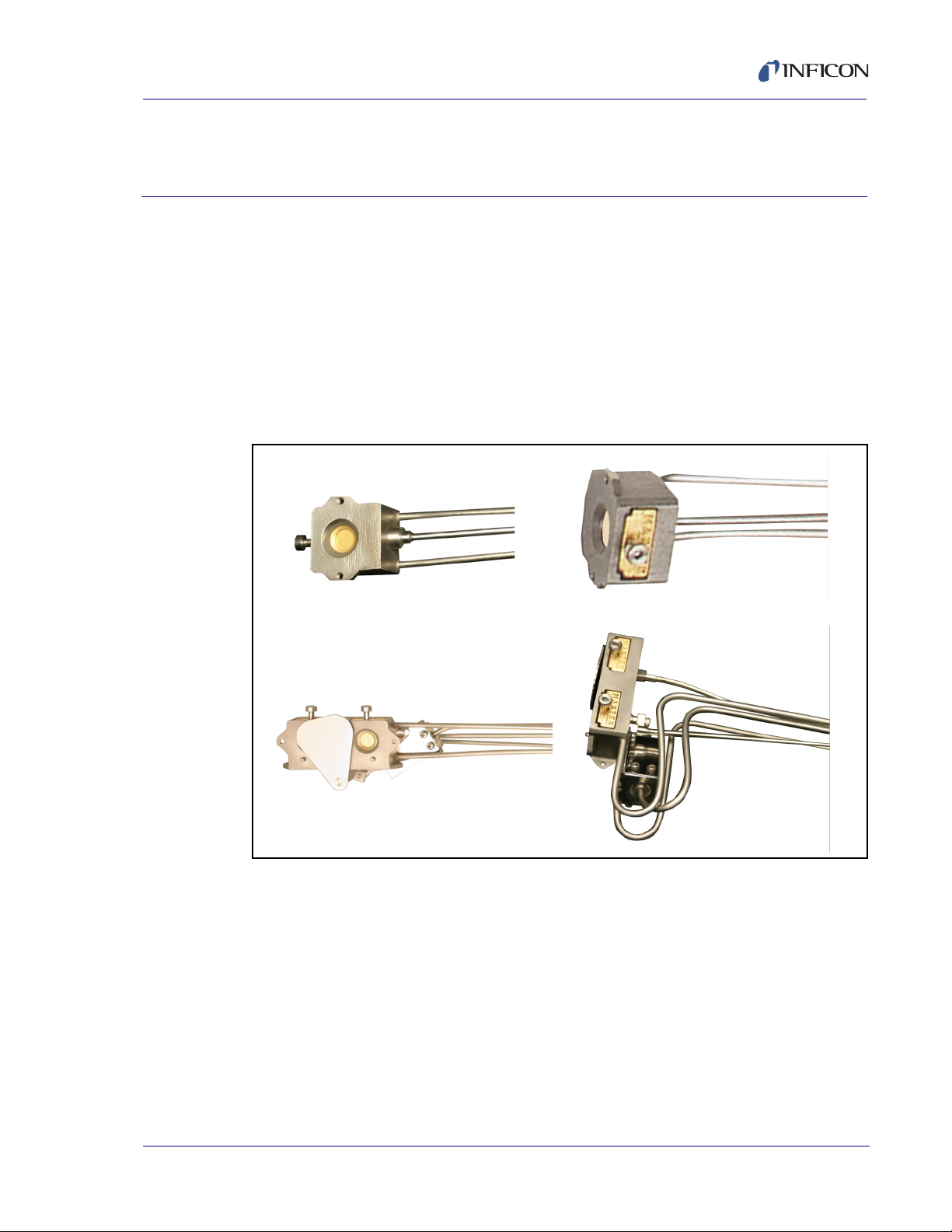
INFICON Cool Drawer
durability combined with excellent thermal stability. The Cool Drawer design allows
crystal installation into the sensor from the side, convenient for systems with
insufficient room for front load crystal installation. Sensors can be ordered in a
sensor and feedthrough combination that can be either welded or assembled with
O-ring compression fittings.
Figure 1-1 Cool Drawer sensors
Cool Drawer Single and Dual Sensors Operating Manual
Introduction
TM
sensors, see Figure 1-1, offer proven reliability and
Chapter 1
PN 074-609-P1A
The Cool Drawer sensor comes in two styles: Single or Dual. Each style is available
in both Standard and Right Angle orientation.
Standard orientation: Cooling tubes are aligned parallel to the crystal face.
Typically installed from the side or bottom of the chamber.
Right Angle orientation: Cooling tubes are aligned perpendicular to the crystal
face. Typically installed from the top of the chamber.
Sensors can be ordered with a pneumatically driven crystal shutter to protect the
crystal during source warm up, or when the sensor is not used during deposition of
an alternate material, or to extend crystal life when used with sampling.
NOTE: A crystal shutter is standard on dual sensors.
1 - 1
Page 12
Cool Drawer Single and Dual Sensors Operating Manual
CAUTION
WARNING
1.2 Definition of Notes, Cautions and Warnings
Before using this manual, please take a moment to understand the Cautions and
Warnings used throughout. They provide pertinent information that is useful in
achieving maximum instrument efficiency while ensuring personal safety.
NOTE: Notes provide additional information about the current topic.
Failure to heed these messages could result in damage
to the sensor.
Failure to heed these messages could result in personal
injury.
1 - 2
PN 074-609-P1A
Page 13

Cool Drawer Single and Dual Sensors Operating Manual
1.3 How to Contact INFICON
Worldwide customer support information is available under Contact >> Support
Worldwide at www.inficon.com
Sales and Customer Service
Technical Support
Repair Service
If experiencing a problem with a Cool Drawer Sensor, please have the following
information readily available:
The Lot Identification Code, located on the side surface of the sensor head.
A description of the problem.
An explanation of any attempts at corrective action.
Exact wording of any error messages received.
1.3.1 Returning Cool Drawer Sensor to INFICON
Do not return any component of the sensor to INFICON without first speaking with
a Customer Support Representative. A Return Material Authorization (RMA)
number must be obtained from the Customer Support Representative.
If a package is delivered to INFICON without an RMA number, the package will be
held and customer contact will be made. This will result in delays in servicing the
sensor.
Prior to being given an RMA number, a Declaration Of Contamination (DOC) form
may need to be completed if the sensor has been exposed to process materials.
DOC forms must be approved by INFICON before an RMA number is issued.
INFICON may require that the sensor be sent to a designated decontamination
facility, not to the factory.
PN 074-609-P1A
1 - 3
Page 14
Cool Drawer Single and Dual Sensors Operating Manual
1.4 Unpacking and Inspection
1 If the Cool Drawer sensor has not been removed from its packaging, do so now.
The sensor and accessories are packaged in a single cardboard carton with a
rigid foam insert. Carefully remove the packaged accessories before removing
the sensor.
2 Carefully examine the sensor for damage that may have occurred during
shipping. This is especially important if obvious rough handling is noticed on the
outside of the container. Immediately report any damage to the carrier and to
INFICON.
NOTE: Do not discard the packing materials until inventory has been taken
and the sensor has been successfully installed.
3 Take an inventory of the order by referring to the order invoice and the
information contained in section 1.5.5 or section 1.6.4.
4 Install the sensor by following the installation instructions found in Chapter 2,
Sensor Installation.
For additional information or technical assistance, contact INFICON (refer to
section 1.3 on page 1-3).
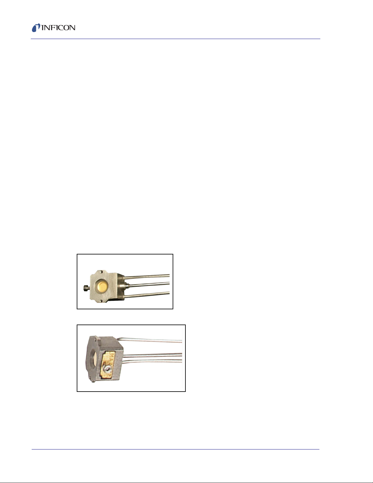
1.5 Cool Drawer Single Sensor (PN CDS-XXXXX)
Figure 1-2 Standard sensor
Figure 1-3 Right Angle sensor
PN 074-609-P1A
1 - 4
Page 15

1.5.1 Specifications
Maximum bakeout temperature with no water
O-ring compression fitting terminations . . . . . . . . . . . . . . . .165°C
Welded terminations. . . . . . . . . . . . . . . . . . . . . . . . . . . . . . .200°C
Maximum operating isothermal environment
temperature with minimum water flow
O-ring compression fitting terminations . . . . . . . . . . . . . . . .300°C
Welded terminations. . . . . . . . . . . . . . . . . . . . . . . . . . . . . . .450°C
1.5.1.1 Size
Maximum envelope
without shutter . . . . . . . . . . . . . . . . . Standard Sensor
Cool Drawer Single and Dual Sensors Operating Manual
3.38 x 3.07 x 1.80 cm
(1.33 x 1.21 x 0.71 in.)
See Figure 1-5 on page 1-9.
Right Angle Sensor
3.24 x 3.63. x 1.80 cm
(1.27 x 1.43 x 0.71 in.)
See Figure 1-5 on page 1-9.
Length of sensor. . . . . . . . . . . . . . . . 10.2 to 66.0 cm (4 to 26 in.)
Water and conduit tubes. . . . . . . . . . 3.175 mm (1/8 in.) OD
seamless stainless steel,
0.406 mm (0.016 in.) wall thickness
Crystal exchange . . . . . . . . . . . . . . . Side loading, self-contained package
Crystal . . . . . . . . . . . . . . . . . . . . . . . 14 mm (0.550 in.) diameter
Mounting. . . . . . . . . . . . . . . . . . . . . . Two #4-40 tapped holes on the back of the
sensor body
PN 074-609-P1A
1 - 5
Page 16
Cool Drawer Single and Dual Sensors Operating Manual
CAUTION
WARNING
1.5.2 Installation Requirements
Feedthrough. . . . . . . . . . . . . . . . . . . INFICON provided CF40 feedthrough or
Other . . . . . . . . . . . . . . . . . . . . . . . . XIU or oscillator to match specific
Water Flow Rate. . . . . . . . . . . . . . . . Minimum 150 to 200 cm
Water Quality . . . . . . . . . . . . . . . . . . Coolant should not contain chlorides as
2.54 cm (1 in.) bolt feedthrough
controller/monitor
CDS-X1XXX only: Solenoid Valve for air
PN 750-420-G1 (see section 3.1 on page
3-1)
3
/min,
30°C maximum
stress corrosion cracking may occur.
Extremely dirty water may result in loss of
cooling capacity.
Do not allow water tubes to freeze. This may happen if the
tubes pass through a cryogenic shroud and the flow of
fluid is interrupted.
Air (shutttered sensors only) . . . . . . 55 PSIG {70 PSIA} (3.8 bar)
[379 kPa](minimum)
60 PSIG {75 PSIA} (4.1 bar)
[414 kPa](maximum)
Do not exceed 100 PSIG (115 PSIA) (6.9 bar) [689 kPa].
Connection to excessive pressure may result in personal
injury or equipment damage.
PN 074-609-P1A
1 - 6
Page 17

Cool Drawer Single and Dual Sensors Operating Manual
WARNING
1.5.3 Materials
Body and Drawer . . . . . . . . . . . . . . . Stainless steel, gold plated Cool Drawer
Springs, Electrical Contacts . . . . . . . Au plated Be-Ni
Water and conduit tubes . . . . . . . . . 304 stainless steel
Wire . . . . . . . . . . . . . . . . . . . . . . . . . Silicon insulated copper
Braze . . . . . . . . . . . . . . . . . . . . . . . . Vacuum process high temperature Ni-In
1.5.4 Specifications for the Single Shutter
Temperature . . . . . . . . . . . . . . . . . . . 165°C (300°C if properly attached to water
Air Tube . . . . . . . . . . . . . . . . . . . . . . SS-104, 3.175 mm (1/8 in.) OD x 0.381 mm
Materials. . . . . . . . . . . . . . . . . . . . . . 100 series stainless steel
Pressure . . . . . . . . . . . . . . . . . . . . . . 55 PSIG {70 PSIA} (3.8 bar)
cooled sensor)
(0.015 in.) wall thickness seamless stainless
steel
[379 kPa] (minimum)
60 PSIG {75 PSIA} (4.1 bar)
[414 kPa] (maximum)
Do not exceed 100 PSIG (115 PSIA) (6.9 bar) [689 kPa].
Connection to excessive pressure may result in personal
injury or equipment damage.
Shutter . . . . . . . . . . . . . . . . . . . . . . . Pneumatically operated. Shutter swings
aside for easy crystal exchange.
Braze . . . . . . . . . . . . . . . . . . . . . . . . Vacuum process high temperature
PN 074-609-P1A
(Ni-Cr alloy)
1 - 7
Page 18

Cool Drawer Single and Dual Sensors Operating Manual
A
B
3
4
0
1
7
8
F
Type of Sensor
(crystals sold separately)
Standard Cool Drawer
(water lines parallel to crystal face)
Right angle Cool Drawer
(water lines perpendicular to
crystal face)
Shutter Assembly
None
Standard shutter
Length of Sensor –
SEE NOTE 1
Length – 10.2 to 66 cm
(4 to 26 in.)
Feedthrough Connection
Sensor welded to feedthrough
– SEE NOTE 3
Feedthrough equipped with
Ultra-Torr
®
compression fittings (allows for adjustable
sensor length). Not available
with CF40 feedthrough and
shutter combination.
Feedthrough –
SEE NOTES 2 and 5
1 in. bolt
CF40
C D S –
NOTE 1:
Orders for a WELDED sensor/feedthrough combination cannot
be accepted without a completed sensor length specification
form (provided by INFICON). Once a welded sensor order is
confirmed, it cannot be canceled.
NOTE 2:
Feedthrough configuration varies depending on options selected
(type of feedthrough, and connection). Example: CDS-A1F47
and -B1F47 use a two-piece hybrid feedthrough design due to
dimensional limits of a standard CF40.
NOTE 3:
Sensor lengths are measured from center of the crystal to the
vacuum side (sealing surface) of the feedthrough (see length
specification form).
NOTE 4:
For sensors ordered without a weld connection (option “8”),
tubes are made to a length of approximately 76.2 cm (30 in.)
for standard sensors and approximately 66 cm (26 in.) for
right angle sensors.
Note 5:
Cool Drawer sensors are not available without a feedthrough.
1.5.5 Parts and Options Overview (Single Sensor)
Cool Drawer Single Sensor . . . . . . . CDS-XXXXX (See Figure 1-4)
Figure 1-4 Cool Drawer single sensor configurations
The following single sensor outline drawings provide dimensions and other
relevant data necessary for planning equipment configurations.
Figure 1-5. . . . . . . . . . . . . . . . . . . . . Cool Drawer Sensors with 2.54 cm (1 in.) bolt
Figure 1-6. . . . . . . . . . . . . . . . . . . . . Cool Drawer sensors welded to CF 40
Figure 1-7. . . . . . . . . . . . . . . . . . . . . Standard Cool Drawer sensor length with
Figure 1-8. . . . . . . . . . . . . . . . . . . . . Right Angle Cool Drawer sensor length with
1.5.6 Single Sensor Drawings
1 - 8
and O-ring compression fittings
shutter
shutter
PN 074-609-P1A
Page 19

Cool Drawer Single and Dual Sensors Operating Manual
CDS-A0F47
CDS-B0F47
CDS-A0F47
CDS-B0F47
CDS-A0F47
CDS-B0F47
Figure 1-5 Cool Drawer sensors with 2.54 cm (1 in.) bolt and compression fittings
Figure 1-6 Cool Drawer sensors welded to CF 40
PN 074-609-P1A
1 - 9
Page 20

Cool Drawer Single and Dual Sensors Operating Manual
1.20 cm
(0.475 in.)
REF
Centerline of crystal aperture
10.2 - 66 cm
(4 - 26 in.)
(0.150 in.)
REF
This gap is shown for clarity. The actual dimension equals 0.
10.2 - 66 cm
(4 - 26 in.)
Figure 1-7 Standard Cool Drawer sensor length with shutter
Figure 1-8 Right Angle Cool Drawer sensor length with shutter
Surface of sensor crystal
0.38 cm
1 - 10
PN 074-609-P1A
Page 21

Cool Drawer Single and Dual Sensors Operating Manual
1.6 Cool Drawer Dual Sensor (PN CDD-XXXX)
Figure 1-9 Cool Drawer dual crystal sensor
1.6.1 Specifications
Maximum bakeout temperature with no water
O-ring compression fitting terminations . . . . . . . . . . . . . . . .165°C
Welded terminations. . . . . . . . . . . . . . . . . . . . . . . . . . . . . . .200°C
Maximum operating isothermal environment
temperature with minimum water flow
O-ring compression fitting terminations . . . . . . . . . . . . . . . .300°C
Welded terminations. . . . . . . . . . . . . . . . . . . . . . . . . . . . . . .450°C
PN 074-609-P1A
1 - 11
Page 22

1.6.1.1 Size
Cool Drawer Single and Dual Sensors Operating Manual
Maximum envelope
without shutter . . . . . . . . . . . . . . . . . Standard Sensor
4.70 x 6.35 x 5.08 cm
(1.85 x 2.50 x 2.00 in.)
Figure 1-11 on page 1-15
Right Angle Sensor
4.70 x 10.54 x 4.45 cm
(1.85 x 4.15 x 1.75 in.)
Figure 1-11 on page 1-15
Length of sensor . . . . . . . . . . . . . . . 10.2 to 66.0 cm (4 to 26 in.)
Water and conduit tubes . . . . . . . . . 3.175 mm (1/8 in.) OD
seamless stainless steel,
0.406 mm (0.016 in.) wall thickness
Crystal exchange . . . . . . . . . . . . . . . Side loading, self-contained package
Crystal . . . . . . . . . . . . . . . . . . . . . . . 14 mm (0.550 in.) diameter
Mounting . . . . . . . . . . . . . . . . . . . . . Four #4-40 tapped holes on the back of the
sensor body
1 - 12
PN 074-609-P1A
Page 23

Cool Drawer Single and Dual Sensors Operating Manual
CAUTION
WARNING
1.6.2 Installation Requirements
Feedthrough . . . . . . . . . . . . . . . . . . . INFICON provided CF40 feedthrough or
Other . . . . . . . . . . . . . . . . . . . . . . . . XIU or oscillator to match specific
Water Flow Rate. . . . . . . . . . . . . . . . Minimum 150 to 200 cm
Water Quality . . . . . . . . . . . . . . . . . . Coolant should not contain chlorides as
2.54 cm (1 in.) bolt feedthrough
controller/monitor
Solenoid Valve for air
PN 750-420-G1 (see section 3.1 on page
3-1)
3
/min,
30°C maximum
stress corrosion cracking may occur.
Extremely dirty water may result in loss of
cooling capacity.
Do not allow water tubes to freeze. This may happen if the
tubes pass through a cryogenic shroud and the flow of
fluid is interrupted.
Air . . . . . . . . . . . . . . . . . . . . . . . . . . . 55 PSIG {70 PSIA} (3.8 bar)
[379 kPa](minimum)
60 PSIG {75 PSIA} (4.1 bar)
[414 kPa](maximum)
Do not exceed 100 PSIG (115 PSIA) (6.9 bar) [689 kPa].
Connection to excessive pressure may result in personal
PN 074-609-P1A
injury or equipment damage.
1.6.3 Materials
Body and Drawer . . . . . . . . . . . . . . . Stainless steel, gold plated Cool Drawer
Springs, Electrical Contacts . . . . . . . Au plated Be-Ni
Water and conduit tubes. . . . . . . . . . 304 stainless steel
Wire . . . . . . . . . . . . . . . . . . . . . . . . . Silicon insulated copper
Braze . . . . . . . . . . . . . . . . . . . . . . . . Vacuum process high temperature Ni-In
1 - 13
Page 24

Cool Drawer Single and Dual Sensors Operating Manual
3
4
7
8
F
C D D –
A
B
Type of Sensor
(crystals sold separately)
Standard Cool Drawer Dual sensor
(water lines parallel to crystal face)
with shutter
Right angle Cool Drawer Dual sensor
(water lines perpendicular to
crystal face) with shutter
Length of Sensor – SEE NOTE 3
Length – 10.2 to 66 cm (4 to 26 in.)
SEE NOTE 4
Feedthrough Connection
Sensor welded to feedthrough –
Feedthrough equipped with
Ultra-Torr
®
compression fittings
(allows for adjustable sensor
length). Not available with CF40
feedthrough.
Feedthrough –
SEE NOTES 2 and 5
1 in. bolt
CF40 (two piece)
NOTE 1:
Orders for a WELDED sensor/feedthrough combination cannot
be accepted without a completed sensor length specification
form (provided by INFICON). Once a welded sensor order is
confirmed, it cannot be canceled.
Note 2:
Feedthrough configuration varies depending on options selected
(type of feedthrough, and connection). Example: CDD-AF47
and -BF47 use a two-piece hybrid feedthrough design due to
dimensional limits of a standard CF40.
Note 3:
Sensor lengths are measured from center of the crystal
closest to the end of the sensor to the vacuum side (sealing
surface) of the feedthrough (see length specification form).
Note 4:
For sensors ordered without a weld connection (option “8”),
tubes are made to a length of approximately 76.2 cm (30 in.)
for standard sensors and approximately 66 cm (26 in.) for
right angle sensors.
Note 5:
Cool Drawer sensors are not available without a feedthrough.
1.6.4 Parts and Options Overview (Dual Sensor)
Cool Drawer Dual Sensor . . . . . . . . CDD-XXXX (See Figure 1-10)
Figure 1-10 Cool Drawer dual sensor configurations
1 - 14
PN 074-609-P1A
Page 25

Cool Drawer Single and Dual Sensors Operating Manual
1.27
(.50”)
5.08
(2.0”)
.76
(.300”)
1.8
(.71”)
6.35
(2.5”)
1.6.5 Dual Sensor Drawings
Figure 1-11 displays Standard and Right Angle dual sensor outline drawings which
provide dimensions and other relevant data necessary for planning equipment
configurations.
Figure 1-11 Standard and Right Angle configuration Cool Drawer dual sensors
PN 074-609-P1A
1.7 Replacement Parts and Accessories
Retainer Assembly with Ceramic Insulator. . . . . . . . . . . . . .PN 123259
Crystal Drawer and Retainer Assembly
(Includes 123259 and 123261). . . . . . . . . . . . . . . . . . . . . . .PN 123260
Crystal Drawer . . . . . . . . . . . . . . . . . . . . . . . . . . . . . . . . . . .PN 123261
1 - 15
Page 26

Cool Drawer Single and Dual Sensors Operating Manual
This page is intentionally blank.
1 - 16
PN 074-609-P1A
Page 27
Cool Drawer Single and Dual Sensors Operating Manual
CAUTION
2.1 Pre-installation Sensor Check
Prior to installing the sensor in the vacuum system, make certain that it is in proper
working condition by following the appropriate procedure.
The sensor head, water tube, etc., should be clean and
free of grease when installed in the vacuum chamber.
Clean nylon gloves should be worn while handling. If
parts do become contaminated, clean them thoroughly
using a suitable solvent to avoid outgassing.
2.1.1 Sensor Installation with a XTC/3™, IC6™ or
Cygnus 2
™
Deposition Controller
Chapter 2
Sensor Installation
1 Connect one end of the 15.2 cm (6 in.) BNC cable (PN 755-257-G6) to the BNC
connector on the feedthrough.
2 Connect the other end of the 15.2 cm (6 in.) BNC cable to the connector of the
Modelock oscillator (XIU) (PN 781-600-GX).
3 Connect one end of the XIU cable (PN 600-1261-GXX) to the mating connector
of the XIU.
4 Connect the other end of the XIU cable to a sensor channel at the rear of the
controller.
5 Install the crystal as instructed by section 4.4 on page 4-10.
6 Connect power to the controller.
PN 074-609-P1A
7 Set the power switch ON.
8 Set density at 1.00 g/cm
3
.
9 Zero thickness.
10 The display should indicate 0 or ±0.001 kÅ.
Crystal life should read from 0 to 5%.
11 Breathe heavily on the crystal. A thickness indication of 1.000 to 2.000 kÅ
should appear on the display. When the moisture evaporates, the thickness
indication should return to approximately zero.
If the above conditions are observed, the sensor is in proper working order and
may be installed.
2 - 1
Page 28

Cool Drawer Single and Dual Sensors Operating Manual
2.1.2 Sensor Installation with a SQM-160™, SQC-310™, SQM-242™,
™
IQM-233
1 Connect one end of the 15.2 cm (6 in.) BNC cable (PN 782-902-011) to the
2 Connect the other end of the 15.2 cm (6 in.) BNC cable to the connector of the
3 Connect one end of the oscillator cable (PN 782-902-012-XX) to the mating
4 Connect the other end of the oscillator cable to a sensor connector at the rear
5 Install the crystal as instructed by section 4.4 on page 4-10.
6 Connect power to the controller.
7 Set the power switch ON.
8 For the SQM-242 or IQM-233 card, launch the appropriate software.
9 Set density at 1.00 g/cm
, STM-2XM™, or STM-3™ Deposition Controller/Monitor
BNC connector on the feedthrough.
oscillator (PN 782-900-010 or 783-500-013) labeled "Feedthrough" or
"Sensor."
connector of the oscillator labeled "Instrument" or "Control Unit."
of the controller/monitor.
3
.
10 Zero thickness.
11 The display should indicate 0 or ±0.001 kÅ.
Crystal life should read from 95% to 100%.
12 Breathe heavily on the crystal. A thickness indication of 1.000 to 2.000 kÅ
should appear on the display. When the moisture evaporates, the thickness
indication should return to approximately zero.
If the above conditions are observed, the sensor is in proper working order and
may be installed.
PN 074-609-P1A
2 - 2
Page 29

Cool Drawer Single and Dual Sensors Operating Manual
2.1.3 Sensor Installation with a Q-pod™ or STM-2™ Deposition Monitor
1 Connect one end of the 15.2 cm (6 in.) BNC cable (PN 782-902-011) to the
BNC connector on the feedthrough.
2 Connect the other end of the 15.2 cm (6 in.) BNC cable to the connector on
Q-pod or STM-2.
3 Connect one end of the USB cable (PN 068-0472) to the mating connector on
Q-pod or STM-2.
4 Connect the other end of the USB cable to a USB port on the computer used
to operate Q-pod or STM-2.
5 Install the crystal as instructed by section 4.4 on page 4-10.
6 Launch the appropriate monitor software.
7 Set density at 1.00 g/cm
8 Zero thickness.
9 The display should indicate 0 or ±0.001 kÅ.
Crystal life should read from 95% to 100%.
The green indicator on Q-pod should be illuminated.
All STM-2 error indicators should be extinguished.
3
.
10 Breathe heavily on the crystal. A thickness indication of 1.000 to 2.000 kÅ
should appear on the display. When the moisture evaporates, the thickness
indication should return to approximately zero.
If the above conditions are observed, the sensor is in proper working order and may
be installed.
2.2 General Guidelines
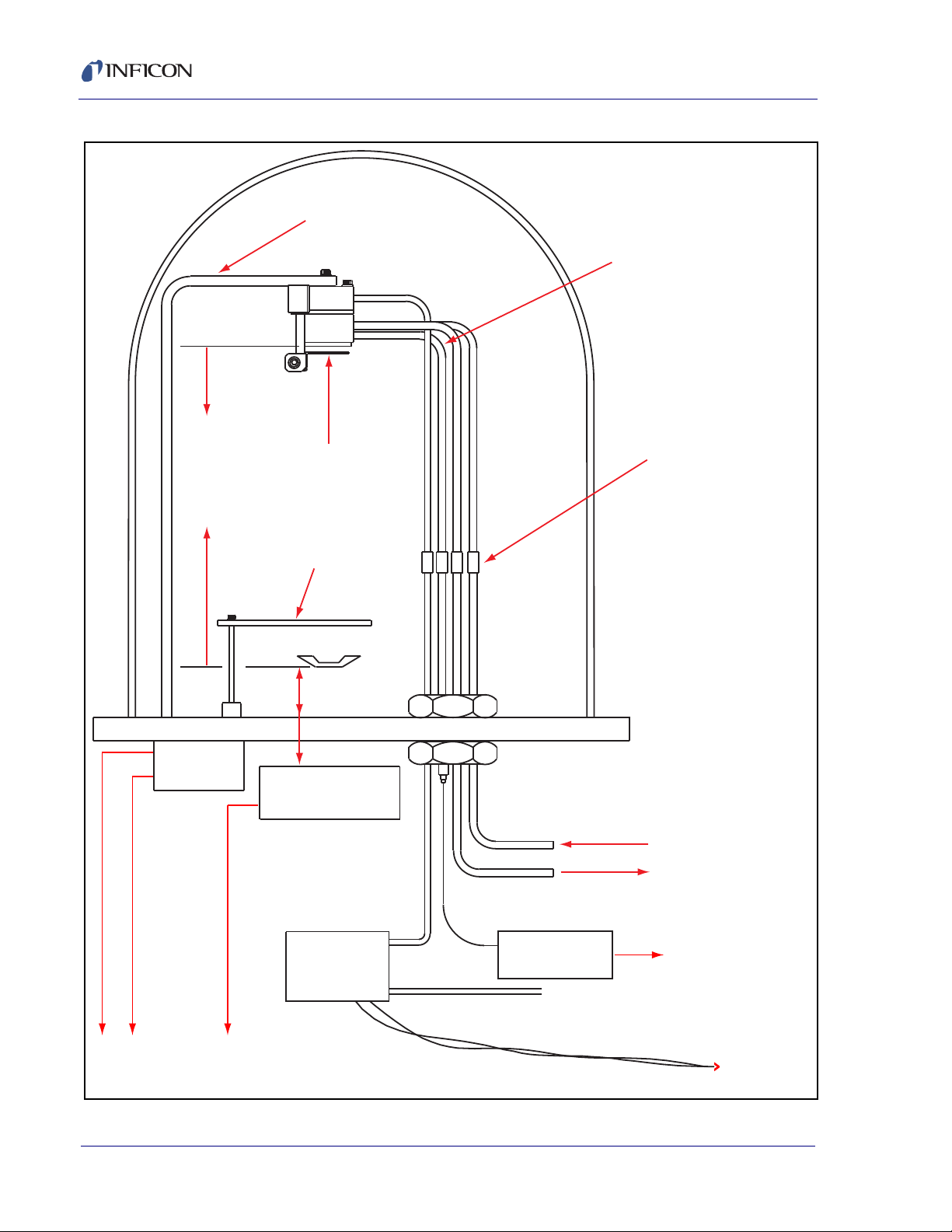
Figure 2-1 shows the typical installation of an INFICON water-cooled crystal
sensor in the vacuum process chamber. Use the illustration and the following
PN 074-609-P1A
guidelines to install the sensor for optimum performance and convenience.
2 - 3
Page 30
Cool Drawer Single and Dual Sensors Operating Manual
>
Mounting Bracket
Conduit Tube
Braze/Weld Joint
or Compression Fittings
Source
to
Sensor
25.4 cm
(10 in.)
Minimum
Sensor
Shutter
Source
Pneumatic
Actuator
PN 750-420-G1
Solenoid
Valve
Instrument Chassis
To
Source Controller
XIU (Oscillator)
To
Sensor
Shutter
Water In
Water Out
Air Supply
Source
Shutter
Figure 2-1 Typical installation
PN 074-609-P1A
2 - 4
Page 31
2.2.1 Sensor Installation
Correct
Incorrect
Correct
Incorrect
Incorrect
Obstruction
Source
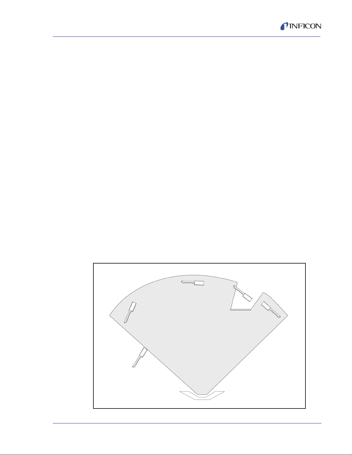
The sensor head must be installed such that the face of the crystal is at 90° relative
to the source. That is, the crystal must be square to the vapor stream. Two effects
may arise if the sensor head is not square to the vapor stream:
The deposit is not even across the crystal surface.
The edge of the crystal that is angled away from the source is farther away from
the source and receives somewhat less material, causing the thickness of the
deposit to become wedge shaped. This wedge shape in the deposited film
tends to reduce the activity of the crystal at its primary resonance.
The area of the deposit shifts from the center of the crystal.
This is due to the shadowing effect of the crystal aperture. If the crystal is not
square to the evaporant stream, the strength of spurious (non-thickness shear)
modes of vibration are enhanced. If the activity of these spurious modes of
oscillation become strong enough, they cause short-term perturbation of the
fundamental frequency. If they get very strong, the oscillator can look onto the
spurious mode of oscillation, causing a mode hop.
The combination of these effects will have a negative effect on crystal life and will
increase the probability of mode hops.
Cool Drawer Single and Dual Sensors Operating Manual
PN 074-609-P1A
Install the sensor as far as possible from the evaporation source (a minimum of
25.4 cm or 10 in.) while keeping the sensor in a position to accumulate thickness
at a rate proportional to accumulation on the substrate. Figure 2-2 shows proper
and improper methods of installing sensors.
NOTE: For best process reproducibility, rigidly support the sensor so that it cannot
move during maintenance and crystal replacement.
Figure 2-2 Sensor installation guidelines
2 - 5
Page 32

Cool Drawer Single and Dual Sensors Operating Manual
To guard against spattering, use a source shutter to shield the sensor during initial
soak periods. If the crystal is hit with only a very small particle of molten material,
it may be damaged and stop oscillating. Even in cases when it does not completely
stop oscillating, the crystal may immediately become unstable, or shortly after
deposition begins, instability may occur.
Plan the installation to ensure there are no obstructions blocking a direct path
between the sensor and the source.
Install sensors in such a manner that the center axis of the crystal is aimed directly
at the source to be monitored. Verify that the sensor location (with reference to the
source) is well within the evaporant stream. Make sure the sensor is square to the
vapor stream.
NOTE: In many cases installing multiple sensors to monitor one source will
improve thickness accuracy. The rules for multiple sensors are the same
as for a single sensor installation, and the locations chosen must be as
defined above. Consult the monitor or controller manual for more
information regarding the availability of this feature.
A technical description may be found in the 39th Annual Conference Proceedings,
Society of Vacuum Coaters, Reducing Process Variation Through Multiple Point
Crystal Sensor Monitoring, J. Kushneir, C. Gogol, J. Blaise, pp19-23, ISSN
0737-5921 (1996).
2.2.1.1 Sensor Installation Procedure
1 Install all water tube connections, if applicable.
2 Install the sensor and feedthrough assembly into the process system and
secure all retaining hardware.
3 Connect the external water tubes from the feedthrough to the water supply
system and flow controller. Use detachable couples (Swagelok
for external water tube connections.
4 Apply water pressure and verify the water connections.
Because of geometric factors, variations in surface temperature, and differences
in electrical potential, the crystal and substrates often do not receive the same
amount of material. Calibration is required to make sure the thickness indication
on the instrument accurately represents the thickness on the substrates.
Refer to the instrument operating manual for calibration procedures.
®
or equivalent)
PN 074-609-P1A
2 - 6
Page 33

2.3 Bending Tubes
CAUTION
2.54 cm (1 in.)
Minimum to
Start of bend
R.375
Minimum
R.375
Minimum
2.54 cm (1 in.)
Minimum to
Start of bend
R.375
Minimum
Do Not Pinch Tube Do Not Twist Tube Do Not Make
Small Radius Bends
Do Not Make
Acute Angle Bends
Read this entire section before attempting to bend the
tubes. Incorrect tube bending that damages the tubes
beyond repair voids the warranty.
If it is necessary to bend the tubes to clear obstacles inside the chamber or to bring
the head into a proper mounting location, observe the following precautions:
Support the tubes where the bends will be placed to avoid a tube being
collapsed or pinched. See Figure 2-3.
If the cooling tube is collapsed, water flow will be restricted. The sensor will
not have sufficient cooling.
If the air tube is collapsed, air pressure maybe restricted. The shutter will
not operate correctly.
An electrical tube that is collapsed or pinched may cause an electrical short.
Do not make sharp bends. Allow a minimum of 9.5 mm (3/8 in.) bend radius.
Cool Drawer Single and Dual Sensors Operating Manual
Bends must be farther than 2.54 cm (1 in.) away from the braze joint at the
electrical connector. Bends that are closer will permanently short out the
electrical connection or damage the braze joint and void the warranty.
The 3.175 mm (1/8 in.) tubes are flexible enough to bend, but they are not designed
for repeat bending. Plan bends wisely. Before the actual tube bending, verify the
bend position again to avoid readjusting. If in doubt, contact INFICON support,
refer to section 1.3, How to Contact INFICON, on page 1-3.
Figure 2-3 Correctly bending tubes
PN 074-609-P1A
2 - 7
Page 34

Cool Drawer Single and Dual Sensors Operating Manual
WARNING
2.4 Installing the Standard and Right Angle Sensors
Standard and Right Angle sensors may be installed in any appropriate location
within the vacuum system. Two tapped holes are provided on the back of each
single sensor body, and four tapped holes on each dual sensor body, for attaching
to the vacuum system.
2.5 Sensor Shutter Function Check
Temporarily connect an air supply to the actuator air tube and test operation for
10 to 15 cycles.
NOTE: The air supply must be 55 PSIG (70 PSIA) to 60 PSIG (75 PSIA)
(3.8 to 4.1 bar) (379 to 414 kPa)
When actuated, shutter movement should be smooth, rapid, and complete, and
should retract completely from the crystal opening. When deactivated, the shutter
should completely cover the crystal opening. Repositioning of the shutter may be
required to achieve optimum on/off positioning.
If operation is impaired, lubricate the moving parts with molybdenum disulfide or
equivalent.
NOTE: A solenoid valve (PN 750-420-G1) is required with any new shutter
installation. See Chapter 3 for more information on the solenoid valve and
its installation.
Do not exceed 100 PSIG (115 PSIA) (6.9 bar) [689 kPa].
Connection to excessive pressure may result in personal
injury or equipment damage.
PN 074-609-P1A
2 - 8
Page 35

Cool Drawer Single and Dual Sensors Operating Manual
2.6 Shutter Operation
The shutter shields the crystal from molten pieces of material during the
preconditioning and conditioning phases of a process. A dual sensor head comes
standard with one shutter to protect the secondary crystal during the process.
2.6.1 Dual Sensor Head Shutter
INFICON dual sensor heads are designed to provide automatic crystal failure
backup or to provide separate crystals for use with two different materials. The two
crystals are located side-by-side in a water-cooled housing. Only one crystal is
exposed to the evaporation source. The other crystal is covered by the shutter. The
normally exposed crystal is the primary (crystal 1) and the covered crystal is the
backup (crystal 2). The shutter is moved by pneumatically actuating the bellows
assembly. When the pneumatic valve is open (on), the bellows is actuated which
moves the crystal shutter over crystal 1 to expose crystal 2.
2.6.2 Single Sensor Head Shutter
For the single sensor head type, a shutter covers the crystal. The shutter does not
fully cover the crystal at atmosphere, but once under vacuum, due to the differential
pressure, the shutter rests over the crystal. When the pneumatic valve is open (on),
the air actuates the bellows, which moves the shutter to expose the crystal.
PN 074-609-P1A
2 - 9
Page 36

Cool Drawer Single and Dual Sensors Operating Manual
This page is intentionally blank.
2 - 10
PN 074-609-P1A
Page 37

Cool Drawer Single and Dual Sensors Operating Manual
WARNING
Installation of the Solenoid Valve
3.1 Introduction
The solenoid valve (PN 750-420-G1) and the feedthrough should be installed at
the same time. The same solenoid valve is used for both the 2.54 cm (1 in.) and
the 7 cm (2-3/4 in.) feedthroughs.
For Installation with 2.54 cm (1 in.) Bolts Feedthrough, see section 3.2.
For Installation with 7 cm (2-3/4 in.) Feedthrough, see section 3.3.
NOTE: The air line is 3.175 mm (1/8 in.) as measured on the atmosphere side of
the feedthrough. A user supplied connection from the air supply tube on
the solenoid valve to the air tube on the Cool Drawer sensor is required.
3.2 Installation with 2.54 cm (1 in.) Bolts Feedthrough
Follow the steps below:
Chapter 3
1 Ensure that the O-ring is in place on the bolt.
2 Insert the 2.54 cm (1 in.) bolt such that the hexagonal shaped end of the bolt is
on the vacuum side of the chamber.
3 Add the bracket.
4 Add the washer.
5 Add the feedthrough nut.
6 Tighten the feedthrough nut.
7 Connect the 3.175 mm (1/8 in.) air tube from the "A" port of the solenoid valve
to the air tube on the feedthrough, see Figure 3-1 on page 3-3.
NOTE: The air line is 3.175 mm (1/8 in.) as measured on the atmosphere side
of the feedthrough. A user supplied connection from the air supply tube
PN 074-609-P1A
on the solenoid valve to the air tube on the Cool Drawer sensor is
required.
8 Attach the "P" port of the solenoid valve to a source of air between
55 PSIG (70 PSIA) (3.8 bar) [379 kPa] and 60 PSIG (75 PSIA) (4.1 bar)
[414 kPa], see Figure 3-1 on page 3-3.
Do not exceed 100 PSIG (115 PSIA) (6.9 bar) [689 kPa].
Connection to excessive pressure may result in personal
injury or equipment damage.
3 - 1
Page 38

Cool Drawer Single and Dual Sensors Operating Manual
WARNING
CAUTION
3.3 Installation with 7 cm (2-3/4 in.) Feedthrough
Follow these steps:
1 Align the score line on the valve assembly bracket over the edge of a table or
other square edge.
2 Using pliers, grasp the part of the bracket extending over the edge and push
down. The assembly will break along the score line.
3 Use a file to smooth any rough edges which may occur along the break.
4 Install the feedthrough.
5 Add the valve bracket (modified) to the desired location using two of the
6.35 mm (1/4 in.) clamp bolts located on the flange.
6 Tighten the flange bolts.
7 Connect the 3.175 mm (1/8 in.) air tube from the "A" port of the solenoid valve
to the air tube on the feedthrough, see Figure 3-1.
NOTE: The air line is 3.175 mm (1/8 in.) as measured on the atmosphere side
of the feedthrough. A user supplied connection from the air supply tube
on the solenoid valve to the air tube on the Cool Drawer sensor is
required.
8 Attach the "P" port of the solenoid valve to a source of air between
55 PSIG (70 PSIA) (3.8 bar) [379 kPa] and 60 PSIG (75 PSIA) (4.1 bar)
[414 kPa], see Figure 3-1.
Do not exceed 100 PSIG (115 PSIA) (6.9 bar) [689 kPa].
Connection to excessive pressure may result in personal
injury or equipment damage.
Maximum temperature for the solenoid valve assembly is
105 °C for bakeout and operation.
PN 074-609-P1A
3 - 2
Page 39

Cool Drawer Single and Dual Sensors Operating Manual
To A ir
Fitting Of
Feedthrough
Exhaust
(Normally Open)
A Output
Port
P Supply
(Normally Closed)
Air Supply
Tube Fitting
(Provided With Valve)
3.4 Electrical and Pneumatic Connections
3.4.1 Electrical
To complete installation of the assembly, make electrical connections to either
24 V (ac) or 24 V (dc). Current required is approximately 70 mA.
Figure 3-1 Miniature pneumatic solenoid tube connections
3.5 Solenoid Valve Drawing
The following Solenoid Valve Outline Drawing provides dimensions and other
relevant data necessary for planning equipment configurations.
Figure 3-2 on page 3-4. . . . . . . . . . . Solenoid valve (PN 750-420-G1)
PN 074-609-P1A
3 - 3
Page 40

Cool Drawer Single and Dual Sensors Operating Manual
P Supply
A Output
Exhaust
Indicator
Manual
Override
Hook Up
Wires
5.00 cm
(1.97 in.)
6.50 cm
(2.56 in.)
3.89 cm
(1.532 in.)
5.08 cm
(2.0 in.)
2.94 cm
(1.156 in.)
2.54 cm
(1.0 in.)
4.25 cm
(1.675 in.)
0.94 cm
(0.37 in.)
Figure 3-2 Solenoid valve
PN 074-609-P1A
3 - 4
Page 41

Cool Drawer Single and Dual Sensors Operating Manual
Troubleshooting and Maintenance
4.1 Troubleshooting Guide
If the Cool Drawer sensor fails to function, or appears to have diminished
performance, the following Symptom, Cause, Remedy Table in section 4.2 on
page 4-5 may be helpful.
4.1.1 Troubleshooting
A useful tool for diagnosing sensor head problems is the DMM (Digital MultiMeter).
Disconnect the short oscillator cable from the feedthrough and measure the
resistance from the center pin to ground.
If the reading is less than 10 megohms the source of the leakage should be
found and corrected.
Chapter 4
With the vacuum system open, check for center conductor continuity, a reading
of more than 1
problem. Cleaning contacts may be required.
Another useful diagnostic is to continuity-test the sensor head without a crystal.
Remove the Cool Drawer from the sensor body. The DMM should measure 1
less from the center pin of the feedthrough to ground, see Figure 4-1. Reforming
the leaf springs may be required if the reading is incorrect.
Figure 4-1 Center conductor continuity
PN 074-609-P1A
from the feedthrough to the transducer contact indicates a
or
4 - 1
Page 42
Cool Drawer Single and Dual Sensors Operating Manual
CAUTION
A very useful tool for rapidly evaluating the cause of a persistent "Crystal Fail" is
the test crystal, which is included with each non-modelock oscillator package, this
tool utilizes a packaged crystal at 5.5 MHz and a connector that allows the direct
connection to BNC cables.
The test crystal provides a known "good" monitor crystal that provides a fast means
of isolating sensor problems.
The test crystal is designed as a diagnostic tool, and is
not intended for use in vacuum.
4.1.2 Diagnostic Procedures
The following diagnostic procedures employ the test crystal and DMM to analyze a
constant Crystal Fail message. The symptom is a Crystal Fail message that is
displayed by the deposition controller even after the monitor crystal has been
replaced with a new “good” monitor crystal.
4.1.2.1 Measurement System Diagnostic Procedure
1 Remove the 15.2 cm (6 in.) BNC cable from the feedthrough.
2 Connect the test crystal to the BNC cable.
If the Crystal Fail message disappears after approximately five seconds,
the measurement system is working properly. Reinstall the BNC cable to
the feedthrough. Go to section 4.1.2.2.
If the Crystal Fail message remains, continue at step 3.
3 Disconnect the BNC cable from the oscillator and from the test crystal.
4 Visually inspect the BNC cable to verify that the center pins are seated properly.
5 Use a DMM to verify the electrical connections on the BNC cable, refer to
section 4.1.1.
There must be continuity between the center pins.
There must be isolation between the center pins and the connector shield.
There must be continuity between the connector shields.
Replace the BNC cable if it is defective and repeat step 2 of this procedure.
6 If the BNC cable is not defective, reconnect it to the oscillator and the test
crystal. If the Crystal Fail message remains, contact INFICON (refer to section
1.3 on page 1-3).
PN 074-609-P1A
4 - 2
Page 43

Cool Drawer Single and Dual Sensors Operating Manual
4.1.2.2 Feedthrough Diagnostic Procedure
1 Remove the crystal drawer from the sensor head.
2 Disconnect the 15.2 cm (6 in.) BNC cable from the feedthrough.
3 Using a DMM, verify continuity from the BNC center pin on the feedthrough to
the center pin on the sensor head, refer to section 4.1.1 on page 4-1. A typical
value would be less than 0.2 ohms.
4 Verify isolation of the center pin on the feedthrough from the electrical ground
(feedthrough body). A typical value would be in excess of 10 megohms.
If the feedthrough, conduit tube, or BNC connector is defective, replace them,
reattach the BNC, and repeat this procedure starting at step 1, otherwise continue
at step 5.
5 Verify continuity from the center pin on the BNC connector of the feedthrough
to the center pin on the sensor head.
6 Verify isolation from the center pin to electrical ground (feedthrough body).
If the feedthrough system is found to be defective, look for defective contacts at the
feedthrough to conduit tube connection. Repair or replace the feedthrough as
necessary. Reattach the BNC and repeat this procedure starting at step 1.
Otherwise, continue at step 7.
7 Connect the BNC cable to the feedthrough and disconnect it from the Crystal
Interface Unit (or oscillator)
8 Verify continuity from the center pin of the sensor head to the un-terminated
end of the BNC cable.
9 Verify isolation from the center pin to electrical ground (feedthrough body).
If the feedthrough and BNC cable system is found to be defective, look for defective
contacts at the feedthrough to BNC cable connection. Repair or replace the
feedthrough as necessary, then reattach the BNC cable to the XIU and repeat this
procedure starting at step 2.
PN 074-609-P1A
4 - 3
Page 44

Cool Drawer Single and Dual Sensors Operating Manual
4.1.2.3 System Diagnostics Pass But Crystal Fail Message Remains
If the system is operating properly, yet the Crystal Fail message is still displayed,
perform the following tasks.
1 On the retainer verify that the center rivet is secure. Repair or replace the
retainer as necessary.
2 Inspect the inside of the drawer for a buildup of material. Clean or replace the
drawer as necessary.
After verifying the sensor head contacts, the sensor head/conduit tube connection,
and the retainer contacts, reassemble the system. If the Crystal Fail message
remains, replace the monitor crystal with a good monitor crystal. Verify that the
monitor crystal works properly by inserting it into a known good measurement
system. If problems continue, contact INFICON (refer to section 1.3 on page 1-3).
4 - 4
PN 074-609-P1A
Page 45

Cool Drawer Single and Dual Sensors Operating Manual
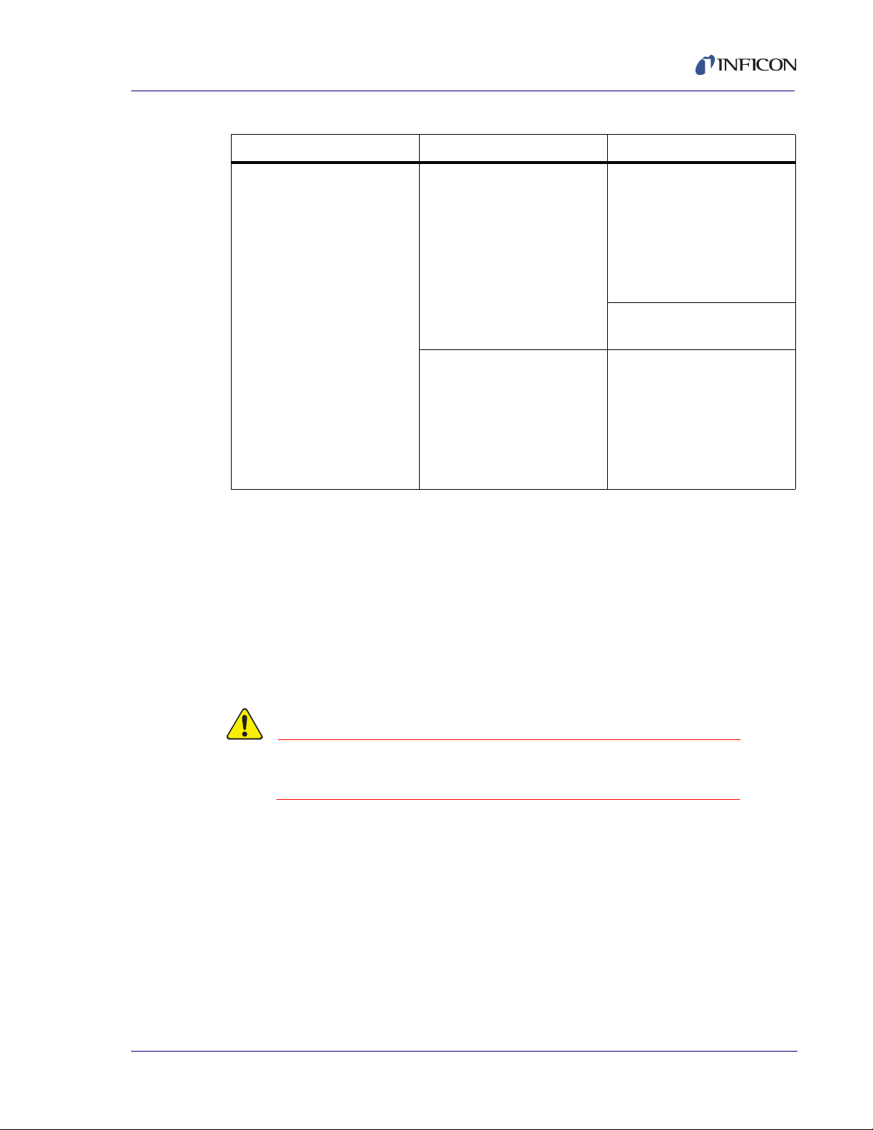
4.2 Symptom, Cause, Remedy
Table 4-1 Symptom, Cause, Remedy
SYMPTOM CAUSE REMEDY
Large jumps of thickness
reading during deposition.
Crystal ceases to oscillate
during deposition before it
reaches its “normal” life.
Mode hopping due to
damaged or heavily damped
crystal.
Crystal is near the end of its
life.
Scratches or foreign particles
on the crystal drawer seating
surface.
Uneven coating. Place the sensor such that
Particles Remove source of particles
Crystal is being hit by small
droplets of molten material
from the evaporation source.
Damaged crystal. Replace the crystal.
Replace the crystal.
Replace the crystal.
Clean or polish the crystal
seating surface on the crystal
drawer. See section 4.5 on
page 4-12.
the crystal is square to the
vapor stream. See section
2.2.1 on page 2-5.
and replace the crystal.
Use a shutter to shield the
sensor during initial period of
evaporation; move the
sensor farther away.
Built-up material on edge of
crystal drawer is touching the
crystal.
PN 074-609-P1A
Material on crystal drawer is
partially masking the full
crystal area.
NOTE: Crystal life is highly dependent on process conditions of rate, power radiated from
source, location, material, and residual gas composition.
The crystal drawer cannot
have a buildup of deposition
material. This material may
create an unreliable
connection to the crystal.
Removal of the deposition
material is a maintenance
necessity. Do not allow seat
to get roughened by the
removal process.
Clean the crystal drawer.
4 - 5
Page 46

Cool Drawer Single and Dual Sensors Operating Manual
Table 4-1 Symptom, Cause, Remedy (continued)
SYMPTOM CAUSE REMEDY
Crystal does not oscillate or
oscillates intermittently (both
in vacuum and in air).
Damaged crystal. Replace the crystal.
Existence of electrical short
or poor electrical contacts.
Check for electrical continuity
and short in sensor contacts;
check for electrical continuity
in feedthroughs, refer to
section 4.1.1 on page 4-1.
NOTE: Check the leaf spring contact shape as part of a routine maintenance inspection.
Flattened or deformed leaf spring contacts in the retainer are common causes of
crystal problems. Lift up each retainer contact spring to a height of approximately
3.3 mm (0.13 in.). See section 4.3.6 on page 4-9.
Crystal oscillates in vacuum
but stops oscillation after
open to air.
Crystal is near the end of its
life; opening to air causes
film oxidation, which
Replace the crystal.
increases film stress.
Excessive moisture
accumulation on the crystal.
Turn off cooling water to
sensor before opening it to
air; flow hot water through
the sensor when the
chamber is open.
Thermal instability: large
changes in thickness reading
during source warm-up
(usually causes thickness
reading to decrease) and
after the termination of
deposition (usually causes
thickness reading to
increase).
Crystal not properly seated. Check and clean the crystal
drawer. See Figure 4-5 on
page 4-12.
Excessive heat applied to the
crystal.
If heat is due to radiation
from the evaporation source,
move sensor farther away
from source and use Low
Thernal Shock crystals for
better thermal stability; if the
source of crystal heating is
due to a secondary electron
beam, change to a sputtering
sensor.
PN 074-609-P1A
4 - 6
No cooling water. Check cooling water flow
rate.
Heat is from electron flux. Use sputtering head for
non-magnetron sputtering.
Page 47
Cool Drawer Single and Dual Sensors Operating Manual
CAUTION
Table 4-1 Symptom, Cause, Remedy (continued)
SYMPTOM CAUSE REMEDY
Poor thickness
reproducibility.
4.3 General Precautions
4.3.1 Handle the Crystal with Care
Wear clean nylon lab gloves and use clean plastic tweezers when handling the
crystal. Handle the crystals only by their edges.
Erratic source emission
characteristics
Material does not adhere to
the crystal.
Move sensor to a different
location; check the
evaporation source for
proper operating conditions;
ensure relatively constant
pool height and avoid
tunneling into the melt.
Use multiple sensor option if
available on controller.
Check the cleanliness of the
crystal surface; evaporate an
intermediate layer of proper
material on the crystal to
improve adhesion. Use silver
or gold coated crystals, as
appropriate.
Anything that comes in contact with the crystal surface may leave contamination,
which may lead to poor film adhesion. Poor film adhesion will result in high rate
noise and premature crystal failure.
Do not use metal tweezers to handle crystals. Metal
PN 074-609-P1A
tweezers may chip the edge of the crystal.
4 - 7
Page 48

Cool Drawer Single and Dual Sensors Operating Manual
4.3.2 Maintain the Temperature of the Crystal
Periodically measure the water flow rate through the crystal sensor to verify that it
meets or exceeds the value specified on page 1-6.
Depending upon the condition of the cooling water used, the addition of an in-line
water filtering cartridge may be necessary to prevent flow obstructions.
Many systems use parallel water supply taps that provide high total flows. In a
parallel water supply system, an obstruction or closed valve in the pipe that
supplies water to the sensor head may not result in a noticeable reduction of total
flow. Therefore, monitor the flow leaving the sensor, not the flow entering the
sensor.
The crystal requires sufficient water cooling to sustain proper operational and
temperature stability. Ideally, a constant heat load is balanced by a constant flow of
water at a constant temperature. INFICON quartz crystals are designed to provide
the best possible stability under normal operating conditions. However, no crystal
can completely eliminate the effects of varying heat loads, such as radiated energy
emanating from the evaporant source or from substrate heaters.
4.3.3 Use the Optimum Crystal Type
Silver crystals are recommended for sputtering applications. Certain materials,
especially dielectrics, may not adhere strongly to the crystal surface and may
cause erratic readings. For many dielectrics, adhesion is improved by using Alloy
crystals. Gold is preferred for other applications. Contact INFICON for an
appropriate crystal for the specific application, refer to section 1.3 on page 1-3.
4.3.4 Crystal Concerns when Opening the Chamber
Thick deposits of some materials, such as SiO, Si and Ni, will normally peel off the
crystal when it is exposed to air, due to changes in film stress caused by gas
absorption. When peeling material is observed, replace the crystal.
PN 074-609-P1A
4 - 8
Page 49

Cool Drawer Single and Dual Sensors Operating Manual
45°
Leaf
Spring
Avoid kinking
leaf spring
4.3.5 Sputtering System Concerns
Cool Drawer sensors are suitable for Magnetron Sputtering and most other
sputtering systems where the plasma is controlled and constrained.
For radio frequency (RF) sputtering systems, the INFICON Sputtering sensor
(PN 750-618-G1) is recommended. Radio frequency (RF) sputtering systems
result in a flux of high-energy electrons which impinge on the sensor head and can
cause significant temperature related thickness errors if the change in the
temperature of the crystal during deposition is significant.
Standard precautions must be taken when installing the Cool Drawer sensor into a
RF sputtering system.
The sensor must be water-cooled and receive a representative sample of the
deposited material (refer to Chapter 2, Sensor Installation).
The installation of the sensor must not disrupt any electrical fields or otherwise
disturb the normal material deposition pattern.
The Cool Drawer sensor must be grounded. Therefore, the Cool Drawer sensor is
not suitable for use in bias sputtering where the sensor must be installed at some
RF potential above ground.
Because the sputtering process is very noisy electrically, it is important to ground
the monitor or controller, as well as the sensor, to the base plate or housing of the
sputtering chamber. Use a wide ground strap to obtain low impedance at radio
frequencies. Normal diameter wires have relatively high impedance at radio
frequencies and may allow a significant voltage to develop between the monitor or
controller and the system. This voltage is unlikely to cause any damage or shock
hazard, but may create an erratic thickness display.
4.3.6 Leaf Spring Maintenance
Leaf spring conditions should be observed as part of the routine maintenance
interval. Insufficient bends or deformities in the leaf spring contacts in the sensor
body are common causes of crystal problems. See Figure 4-2.
PN 074-609-P1A
Figure 4-2 Shaping the retainer leaf spring
4 - 9
Page 50

Cool Drawer Single and Dual Sensors Operating Manual
CAUTION
CAUTION
4.4 Crystal Replacement Instructions
To preserve cleanliness and to maximize crystal
performance, all work should be performed in a clean
room environment.
1 Using a thumb and index finger, gently squeeze the sides of the retainer at
mid-section, then lift the retainer up, away from the drawer, as shown
in Figure 4-3.
2 Hold the drawer by the handle and turn it upside down to remove the spent
crystal.
3 Prior to installing the new crystal, review section 4.3.1, Handle the Crystal with
Care, on page 4-7.
4 Wear clean nylon gloves and grasp the edge of the new crystal with clean
plastic tweezers.
5 Orient the new crystal so the patterned electrode is facing up.
6 Insert the new crystal in the drawer and release the crystal. The pattern
electrode must be facing up as shown in Figure 4-4.
7 Hold the retainer by its sides. Align its orientation notch with the drawer then
gently and evenly push the retainer down until it snaps firmly into the drawer.
See Figure 4-4.
Never push down (or pull up) on the contact spring, doing
so may permanently damage it.
8 Inspect the entire assembly. The retainer should lay evenly and engage the
drawer at all four corners.
9 Reinstall the drawer into the sensor body. Push the drawer straight in making
certain that it is completely seated in the sensor body.
PN 074-609-P1A
4 - 10
Page 51

Cool Drawer Single and Dual Sensors Operating Manual
CAUTION
Contact Spring
Orientation
Notch
Handle
Retainer
Crystal
Drawer
Figure 4-3 Removing the crystal
Figure 4-4 Replacing the crystal
PN 074-609-P1A
Never deposit material on a sensor without the crystal
drawer, retainer, and crystal installed.
Material deposited on the exposed sensor body
assembly will lead to complete failure of the crystal to
oscillate or premature crystal failure. Removing the
deposited material will require extensive cleaning and
new components.
4 - 11
Page 52

Cool Drawer Single and Dual Sensors Operating Manual
CAUTION
Clean or polish this surface.
Remove all oxides.
Do not scratch.
4.5 Maintenance
4.5.1 Crystal Drawer Maintenance
In dielectric coating applications, the surface where the crystal contacts the crystal
drawer may require periodic cleaning. Since most dielectrics are insulators, any
buildup on the crystal drawer will eventually cause:
erratic or poor electrical contact between the crystal and the crystal drawer.
a reduction in thermal transfer from the crystal to the crystal drawer.
This will result in noisy operation and early crystal failure.
Clean the crystal drawer by ultrasonic cleaning in a soap solution and rinsing.
If necessary, gently buff the drawer (see Figure 4-5) with a white Scotch-Brite
(1200 to 1500 grit) followed by an ultrasonic bath in soap solution and then by a
thorough rinsing in deionized water and drying.
The crystal drawer has a fine finish. This high quality finish is essential to provide
good electrical and thermal contact with the crystal.
® pad
Applying excessive force during cleaning or using overly
abrasive cleaning materials may damage the crystal
drawer finish and reduce sensor performance.
Figure 4-5 Crystal Drawer Cleaning
PN 074-609-P1A
4 - 12
 Loading...