

Page 1
C
over Page
OPERATING MANUAL
™
Composer Elite
Gas Concentration Monitor
PN 074-566-P1B
Page 2

Page 3

www.inficon.com reachus@inficon.com
©2013 INFICON
®
Title P
age
OPERATING MANUAL
Composer Elite
Gas Concentration Monitor
™
PN 074-566-P1B
Page 4

Trademarks
The trademarks of the products mentioned in this manual are held by the companies that
produce them.
Beckhoff® and TwinCAT® are registered trademarks of Beckhoff Automation GmbH.
CIP™ is a registered trademark of Open DeviceNet Vendor Association, Inc.
DeviceNet™ is a registered trademark of Open DeviceNet Vendor Association, Inc.
Inconel® is a registered trademark of International Nickel Company.
INFICON® and Composer Elite™ are trademarks of INFICON GmbH
ODVA™ is a registered trademark of Open DeviceNet Vendor Association, Inc.
Viton® is registered trademark of E. I. duPont de Nemours Company.
VCR® and Swagelok® are registered trademarks of Swagelok, Company.
Windows®, Windows XP®, Window 7®, and Microsoft® are registered trademarks of Microsoft Corporation.
All other brand and product names are trademarks or registered trademarks of their respective companies.
Disclaimer
The information contained in this manual is believed to be accurate and reliable. However, INFICON assumes
no responsibility for its use and shall not be liable for any special, incidental, or consequential damages related
to the use of this product.
Due to our continuing program of product improvements, specifications are subject to change without notice.
Copyright
©2013 All rights reserved.
Reproduction or adaptation of any part of this document without permission is unlawful.
Page 5
Page 6

Page 7

Warranty
WARRANTY AND LIABILITY - LIMITATION: Seller warrants the products
manufactured by it, or by an affiliated company and sold by it, and described on
the reverse hereof, to be, for the period of warranty coverage specified below, free
from defects of materials or workmanship under normal proper use and service.
The period of warranty coverage is specified for the respective products in the
respective Seller instruction manuals for those products but shall not be less than
one (1) year from the date of shipment thereof by Seller. Seller's liability under this
warranty is limited to such of the above products or parts thereof as are returned,
transportation prepaid, to Seller's plant, not later than thirty (30) days after the
expiration of the period of warranty coverage in respect thereof and are found by
Seller's examination to have failed to function properly because of defective
workmanship or materials and not because of improper installation or misuse and
is limited to, at Seller's election, either (a) repairing and returning the product or
part thereof, or (b) furnishing a replacement product or part thereof, transportation
prepaid by Seller in either case. In the event Buyer discovers or learns that a
product does not conform to warranty, Buyer shall immediately notify Seller in
writing of such non-conformity, specifying in reasonable detail the nature of such
non-conformity. If Seller is not provided with such written notification, Seller shall
not be liable for any further damages which could have been avoided if Seller had
been provided with immediate written notification.
THIS WARRANTY IS MADE AND ACCEPTED IN LIEU OF ALL OTHER
WARRANTIES, EXPRESS OR IMPLIED, WHETHER OF MERCHANTABILITY OR
OF FITNESS FOR A PARTICULAR PURPOSE OR OTHERWISE, AS BUYER'S
EXCLUSIVE REMEDY FOR ANY DEFECTS IN THE PRODUCTS TO BE SOLD
HEREUNDER. All other obligations and liabilities of Seller, whether in contract or
tort (including negligence) or otherwise, are expressly EXCLUDED. In no event
shall Seller be liable for any costs, expenses or damages, whether direct or
indirect, special, incidental, consequential, or other, on any claim of any defective
product, in excess of the price paid by Buyer for the product plus return
transportation charges prepaid.
No warranty is made by Seller of any Seller product which has been installed,
used or operated contrary to Seller's written instruction manual or which has been
subjected to misuse, negligence or accident or has been repaired or altered by
anyone other than Seller or which has been used in a manner or for a purpose for
which the Seller product was not designed nor against any defects due to plans or
instructions supplied to Seller by or for Buyer.
This manual is intended for private use by INFICON® Inc. and its customers.
Contact INFICON before reproducing its contents.
NOTE: These instructions do not provide for every contingency that may arise in
connection with the installation, operation or maintenance of this equipment.
Should you require further assistance, please contact INFICON.
www.inficon.com reachus@inficon.com
Page 8

Page 9

Composer Elite Operating Manual
Table Of Contents
Cover Page
Trademarks
Disclaimer
Copyright
Declaration Of Conformity
Warranty
Chapter 1
Introduction
1.1 Introduction. . . . . . . . . . . . . . . . . . . . . . . . . . . . . . . . . . . . . . . . . . . . . . . . . . 1-1
1.1.1 Description of the Composer Elite System . . . . . . . . . . . . . . . . . . . . . . . . . .1-1
1.2 Using this Manual . . . . . . . . . . . . . . . . . . . . . . . . . . . . . . . . . . . . . . . . . . . . . 1-2
1.2.1 Symbols and their Definitions . . . . . . . . . . . . . . . . . . . . . . . . . . . . . . . . . . . . 1-2
1.2.2 General Cautions and Warnings . . . . . . . . . . . . . . . . . . . . . . . . . . . . . . . . .1-3
1.3 How To Contact INFICON . . . . . . . . . . . . . . . . . . . . . . . . . . . . . . . . . . . . . . 1-4
1.3.1 Returning Your Composer Elite . . . . . . . . . . . . . . . . . . . . . . . . . . . . . . . . . .1-4
1.4 Unpacking and Inspection . . . . . . . . . . . . . . . . . . . . . . . . . . . . . . . . . . . . . .1-5
1.4.1 Parts and Options Overview. . . . . . . . . . . . . . . . . . . . . . . . . . . . . . . . . . . . . 1-6
1.4.2 Sensor Control Unit Power-Up Verification . . . . . . . . . . . . . . . . . . . . . . . . .1-7
1.5 Specifications . . . . . . . . . . . . . . . . . . . . . . . . . . . . . . . . . . . . . . . . . . . . . . . . 1-8
1.5.1 Composer Elite System Operating Specifications . . . . . . . . . . . . . . . . . . . .1-8
1.5.2 Composer Elite Sensor Control Unit. . . . . . . . . . . . . . . . . . . . . . . . . . . . . . . 1-9
1.5.3 Acoustic Sensor . . . . . . . . . . . . . . . . . . . . . . . . . . . . . . . . . . . . . . . . . . . . . 1-10
1.5.4 Power Supply . . . . . . . . . . . . . . . . . . . . . . . . . . . . . . . . . . . . . . . . . . . . . . . 1-11
1.5.4.1 Rated Output . . . . . . . . . . . . . . . . . . . . . . . . . . . . . . . . . . . . . . . . . . . . . . .1-11
PN 074-566-P1B
1.5.4.2 Rated Input. . . . . . . . . . . . . . . . . . . . . . . . . . . . . . . . . . . . . . . . . . . . . . . . . 1-12
1.5.4.3 Power Supply Environmental Specifications . . . . . . . . . . . . . . . . . . . . . . .1-12
1.5.5 User Supplied Power Supply . . . . . . . . . . . . . . . . . . . . . . . . . . . . . . . . . . .1-12
1.5.6 Computer Requirements for Composer Elite Multi-Sensor Software . . . . . 1-13
1.5.7 DeviceNet Requirements for Composer Elite Multi-Sensor Software . . . .1-13
1.5.8 Mounting Requirements . . . . . . . . . . . . . . . . . . . . . . . . . . . . . . . . . . . . . . .1-13
1.5.9 Ventilation Requirements . . . . . . . . . . . . . . . . . . . . . . . . . . . . . . . . . . . . . .1-13
1.5.10 Perimeter for Maintenance Access. . . . . . . . . . . . . . . . . . . . . . . . . . . . . . .1-14
1.5.11 Environmental Requirements . . . . . . . . . . . . . . . . . . . . . . . . . . . . . . . . . . .1-14
TOC - 1
Page 10

Composer Elite Operating Manual
Chapter 2
Installation
2.1 Composer Elite Installation Guidelines. . . . . . . . . . . . . . . . . . . . . . . . . . . . . 2-1
2.1.1 Pressure, Temperature, and Tubing . . . . . . . . . . . . . . . . . . . . . . . . . . . . . . 2-1
2.1.1.1 Maximum Pressure . . . . . . . . . . . . . . . . . . . . . . . . . . . . . . . . . . . . . . . . . . . 2-1
2.1.1.2 Pressure and Tubing Size . . . . . . . . . . . . . . . . . . . . . . . . . . . . . . . . . . . . . . 2-2
2.1.1.3 Heated Process Tubing and Acoustic Sensor Temperatures . . . . . . . . . . . 2-2
2.1.2 Grounding and Shielding . . . . . . . . . . . . . . . . . . . . . . . . . . . . . . . . . . . . . . . 2-3
2.1.2.1 Power Supply Grounding Requirement . . . . . . . . . . . . . . . . . . . . . . . . . . . . 2-3
2.1.2.2 Earth Ground Requirement . . . . . . . . . . . . . . . . . . . . . . . . . . . . . . . . . . . . . 2-3
2.1.2.3 Composer Elite System Grounding Requirement . . . . . . . . . . . . . . . . . . . . 2-4
2.1.2.4 Electrical Interference Reduction . . . . . . . . . . . . . . . . . . . . . . . . . . . . . . . . . 2-5
2.1.3 Composer Elite Location Selection . . . . . . . . . . . . . . . . . . . . . . . . . . . . . . . 2-6
2.1.3.1 Selecting The Acoustic Sensor Location . . . . . . . . . . . . . . . . . . . . . . . . . . . 2-6
2.1.3.2 Selecting The Sensor Control Unit Location . . . . . . . . . . . . . . . . . . . . . . . . 2-7
2.2 Composer Elite Installation. . . . . . . . . . . . . . . . . . . . . . . . . . . . . . . . . . . . . . 2-8
2.2.1 Installing The Sensor Control Unit in a 19 in. (48.26 cm) Rack . . . . . . . . . . 2-8
2.2.2 Installing The Acoustic Sensor . . . . . . . . . . . . . . . . . . . . . . . . . . . . . . . . . . . 2-9
2.2.3 Installing Interconnect, Power Supply, and Communications Cables . . . . 2-11
2.2.4 Installing Composer Elite Multi-Sensor Software . . . . . . . . . . . . . . . . . . . . 2-12
Chapter 3
Operation
3.1 Initialization and Setup . . . . . . . . . . . . . . . . . . . . . . . . . . . . . . . . . . . . . . . . . 3-1
3.1.1 Parameter Entry . . . . . . . . . . . . . . . . . . . . . . . . . . . . . . . . . . . . . . . . . . . . . . 3-1
3.1.1.1 Composer Elite Front Panel Parameter Entry . . . . . . . . . . . . . . . . . . . . . . . 3-1
3.2 Calibration . . . . . . . . . . . . . . . . . . . . . . . . . . . . . . . . . . . . . . . . . . . . . . . . . . 3-2
3.2.1 Frequency of Calibration . . . . . . . . . . . . . . . . . . . . . . . . . . . . . . . . . . . . . . . 3-2
3.2.2 Special Tools and Materials . . . . . . . . . . . . . . . . . . . . . . . . . . . . . . . . . . . . . 3-3
3.2.3 How to Calibrate. . . . . . . . . . . . . . . . . . . . . . . . . . . . . . . . . . . . . . . . . . . . . . 3-3
3.2.4 How To Revert To Factory Default Settings. . . . . . . . . . . . . . . . . . . . . . . . . 3-3
3.3 How To Use Composer Elite . . . . . . . . . . . . . . . . . . . . . . . . . . . . . . . . . . . . 3-4
3.3.1 How to Power Up and Power Down Composer Elite . . . . . . . . . . . . . . . . . . 3-4
3.3.2 Composer Elite Screen Descriptions . . . . . . . . . . . . . . . . . . . . . . . . . . . . . . 3-5
3.3.2.1 Boot Screen . . . . . . . . . . . . . . . . . . . . . . . . . . . . . . . . . . . . . . . . . . . . . . . . . 3-5
3.3.2.2 Indicators Displayed On Screens. . . . . . . . . . . . . . . . . . . . . . . . . . . . . . . . . 3-6
3.3.2.3 Overview Screen . . . . . . . . . . . . . . . . . . . . . . . . . . . . . . . . . . . . . . . . . . . . . 3-6
3.3.2.4 System Overview Screen . . . . . . . . . . . . . . . . . . . . . . . . . . . . . . . . . . . . . . . 3-8
3.3.2.5 Errors and Warnings Screen . . . . . . . . . . . . . . . . . . . . . . . . . . . . . . . . . . . . 3-9
PN 074-566-P1B
TOC - 2
Page 11

Composer Elite Operating Manual
3.3.2.6 Sensor Screen . . . . . . . . . . . . . . . . . . . . . . . . . . . . . . . . . . . . . . . . . . . . . . 3-10
3.3.2.7 Sensor Parameters Screen . . . . . . . . . . . . . . . . . . . . . . . . . . . . . . . . . . . .3-12
3.3.3 Description of Rear Panel. . . . . . . . . . . . . . . . . . . . . . . . . . . . . . . . . . . . . . 3-14
3.3.3.1 Power Connector . . . . . . . . . . . . . . . . . . . . . . . . . . . . . . . . . . . . . . . . . . . . 3-14
3.3.3.2 Power Switch . . . . . . . . . . . . . . . . . . . . . . . . . . . . . . . . . . . . . . . . . . . . . . .3-14
3.3.3.3 Ground Stud . . . . . . . . . . . . . . . . . . . . . . . . . . . . . . . . . . . . . . . . . . . . . . . .3-14
3.3.3.4 I/O Slot . . . . . . . . . . . . . . . . . . . . . . . . . . . . . . . . . . . . . . . . . . . . . . . . . . . .3-14
3.3.3.5 Control Slot. . . . . . . . . . . . . . . . . . . . . . . . . . . . . . . . . . . . . . . . . . . . . . . . . 3-15
3.3.3.6 Sensor 5 - I/O Slot . . . . . . . . . . . . . . . . . . . . . . . . . . . . . . . . . . . . . . . . . . . 3-15
3.3.3.7 Sensor Slots 1 - 4. . . . . . . . . . . . . . . . . . . . . . . . . . . . . . . . . . . . . . . . . . . . 3-15
Chapter 4
Applications Guide
4.1 Advice and Tips . . . . . . . . . . . . . . . . . . . . . . . . . . . . . . . . . . . . . . . . . . . . . . 4-1
4.1.1 What is the Required Warm Up Time?. . . . . . . . . . . . . . . . . . . . . . . . . . . . . 4-1
4.1.2 When and How Often to Set the Reference Zero. . . . . . . . . . . . . . . . . . . . .4-1
4.1.3 How is Performance Affected if I Use the
Factory (Reference) Zero Value? . . . . . . . . . . . . . . . . . . . . . . . . . . . . . . . . . 4-2
4.1.4 What To Do when the Specific Heat Ratio
for a Gas is Unknown . . . . . . . . . . . . . . . . . . . . . . . . . . . . . . . . . . . . . . . . . .4-3
4.1.5 What is the Ideal Operating Environment?. . . . . . . . . . . . . . . . . . . . . . . . . .4-4
4.1.6 What is the Effect of Pressure Variation?. . . . . . . . . . . . . . . . . . . . . . . . . . .4-4
4.1.7 What is the Effect of Flow Variation? . . . . . . . . . . . . . . . . . . . . . . . . . . . . . . 4-5
4.1.8 How Does This Instrumental Method Differ from
Measuring the Speed of Sound by Time of Flight? . . . . . . . . . . . . . . . . . . . 4-5
4.1.8.1 Calculation Example. . . . . . . . . . . . . . . . . . . . . . . . . . . . . . . . . . . . . . . . . . . 4-6
4.1.9 What is the Long Term Stability of
this Measurement System? . . . . . . . . . . . . . . . . . . . . . . . . . . . . . . . . . . . . . 4-7
4.1.10 What Happens if the Reference Zero
PN 074-566-P1B
4.1.11 How to Sample Flow with a Composer Elite. . . . . . . . . . . . . . . . . . . . . . . . . 4-9
is Improperly Set?. . . . . . . . . . . . . . . . . . . . . . . . . . . . . . . . . . . . . . . . . . . . .4-8
Chapter 5
Remote Communications
5.1 Introduction. . . . . . . . . . . . . . . . . . . . . . . . . . . . . . . . . . . . . . . . . . . . . . . . . . 5-1
5.2 General Type Definitions for Remote Communications . . . . . . . . . . . . . . . . 5-1
5.3 RS-232 Communications . . . . . . . . . . . . . . . . . . . . . . . . . . . . . . . . . . . . . . . 5-1
5.4 DeviceNet Communications . . . . . . . . . . . . . . . . . . . . . . . . . . . . . . . . . . . . .5-3
5.4.1 DeviceNet Objects . . . . . . . . . . . . . . . . . . . . . . . . . . . . . . . . . . . . . . . . . . . .5-4
5.4.1.1 CIP Type Definitions. . . . . . . . . . . . . . . . . . . . . . . . . . . . . . . . . . . . . . . . . . .5-4
5.4.1.2 Identity Objects (01h) . . . . . . . . . . . . . . . . . . . . . . . . . . . . . . . . . . . . . . . . . . 5-4
TOC - 3
Page 12

Composer Elite Operating Manual
5.4.1.3 Message Router (02h) . . . . . . . . . . . . . . . . . . . . . . . . . . . . . . . . . . . . . . . . . 5-5
5.4.1.4 DeviceNet Object (03h) . . . . . . . . . . . . . . . . . . . . . . . . . . . . . . . . . . . . . . . . 5-5
5.4.1.5 Assembly Object (04h) . . . . . . . . . . . . . . . . . . . . . . . . . . . . . . . . . . . . . . . . . 5-6
5.4.1.6 Connection Object (05h) . . . . . . . . . . . . . . . . . . . . . . . . . . . . . . . . . . . . . . . 5-7
5.4.1.7 Acknowledge Handler Object (2Bh) . . . . . . . . . . . . . . . . . . . . . . . . . . . . . . 5-11
5.4.1.8 I/O Data Format Object (64h). . . . . . . . . . . . . . . . . . . . . . . . . . . . . . . . . . . 5-11
5.4.2 DeviceNet Data Sets . . . . . . . . . . . . . . . . . . . . . . . . . . . . . . . . . . . . . . . . . 5-12
5.4.2.1 Initialization. . . . . . . . . . . . . . . . . . . . . . . . . . . . . . . . . . . . . . . . . . . . . . . . . 5-12
5.4.2.2 Data . . . . . . . . . . . . . . . . . . . . . . . . . . . . . . . . . . . . . . . . . . . . . . . . . . . . . . 5-12
5.4.2.2.1 Data Sets . . . . . . . . . . . . . . . . . . . . . . . . . . . . . . . . . . . . . . . . . . . . . . . . . . 5-12
5.4.2.2.2 Sensor 1-5 Data Set. . . . . . . . . . . . . . . . . . . . . . . . . . . . . . . . . . . . . . . . . . 5-13
5.4.2.2.3 All 5 Sensor Card Data Set . . . . . . . . . . . . . . . . . . . . . . . . . . . . . . . . . . . . 5-14
5.4.2.2.4 Sensors 1,2,3 Error/Warning Data Set. . . . . . . . . . . . . . . . . . . . . . . . . . . . 5-18
5.4.2.2.5 Sensors 4,5 Error/Warning Data Set . . . . . . . . . . . . . . . . . . . . . . . . . . . . . 5-19
5.4.2.2.6 5 Sensors' Concentration Data Set . . . . . . . . . . . . . . . . . . . . . . . . . . . . . . 5-20
5.4.3 DeviceNet INFICON Messaging. . . . . . . . . . . . . . . . . . . . . . . . . . . . . . . . . 5-21
5.5 Message Format . . . . . . . . . . . . . . . . . . . . . . . . . . . . . . . . . . . . . . . . . . . . 5-21
5.5.1 Command. . . . . . . . . . . . . . . . . . . . . . . . . . . . . . . . . . . . . . . . . . . . . . . . . . 5-22
5.5.1.1 Command Packet (Host to Composer Elite Message). . . . . . . . . . . . . . . . 5-22
5.5.2 Response . . . . . . . . . . . . . . . . . . . . . . . . . . . . . . . . . . . . . . . . . . . . . . . . . . 5-22
5.5.2.1 Response Packet (Composer Elite to Host Message) . . . . . . . . . . . . . . . . 5-23
5.5.2.2 Communication Error Codes . . . . . . . . . . . . . . . . . . . . . . . . . . . . . . . . . . . 5-23
5.6 Communication Commands . . . . . . . . . . . . . . . . . . . . . . . . . . . . . . . . . . . . 5-27
5.6.1 Hello Command . . . . . . . . . . . . . . . . . . . . . . . . . . . . . . . . . . . . . . . . . . . . . 5-28
5.6.2 Query Commands . . . . . . . . . . . . . . . . . . . . . . . . . . . . . . . . . . . . . . . . . . . 5-28
5.6.3 Update Commands . . . . . . . . . . . . . . . . . . . . . . . . . . . . . . . . . . . . . . . . . . 5-29
5.6.4 Status Commands . . . . . . . . . . . . . . . . . . . . . . . . . . . . . . . . . . . . . . . . . . . 5-30
5.6.5 Remote Commands . . . . . . . . . . . . . . . . . . . . . . . . . . . . . . . . . . . . . . . . . . 5-36
5.7 Composer Elite Communications Examples . . . . . . . . . . . . . . . . . . . . . . . 5-37
5.7.1 Hello Command, ASCII Name and Version . . . . . . . . . . . . . . . . . . . . . . . . 5-37
5.7.2 Query Command, Carrier Molecular Weight . . . . . . . . . . . . . . . . . . . . . . . 5-37
5.7.3 Update Command, Carrier Molecular Weight . . . . . . . . . . . . . . . . . . . . . . 5-38
5.7.4 Update Command, Set Bit Pattern for S0 Command. . . . . . . . . . . . . . . . . 5-38
5.7.5 Status Command, Current Data . . . . . . . . . . . . . . . . . . . . . . . . . . . . . . . . . 5-39
5.7.6 Remote Command, Zero Frequency . . . . . . . . . . . . . . . . . . . . . . . . . . . . . 5-39
PN 074-566-P1B
TOC - 4
Page 13

Composer Elite Operating Manual
Chapter 6
Composer Elite Multi-Sensor Software
6.1 Introduction. . . . . . . . . . . . . . . . . . . . . . . . . . . . . . . . . . . . . . . . . . . . . . . . . . 6-1
6.2 Hardware Requirements. . . . . . . . . . . . . . . . . . . . . . . . . . . . . . . . . . . . . . . .6-1
6.2.1 Computer Requirements . . . . . . . . . . . . . . . . . . . . . . . . . . . . . . . . . . . . . . .6-1
6.2.2 RS-232 Requirements . . . . . . . . . . . . . . . . . . . . . . . . . . . . . . . . . . . . . . . . . 6-1
6.2.3 DeviceNet Requirements . . . . . . . . . . . . . . . . . . . . . . . . . . . . . . . . . . . . . . . 6-1
6.2.4 Software Installation . . . . . . . . . . . . . . . . . . . . . . . . . . . . . . . . . . . . . . . . . . .6-2
6.3 Operation . . . . . . . . . . . . . . . . . . . . . . . . . . . . . . . . . . . . . . . . . . . . . . . . . . .6-3
6.3.1 User Login . . . . . . . . . . . . . . . . . . . . . . . . . . . . . . . . . . . . . . . . . . . . . . . . . . 6-4
6.3.2 Comm Settings . . . . . . . . . . . . . . . . . . . . . . . . . . . . . . . . . . . . . . . . . . . . . . . 6-4
6.3.3 Data Storage . . . . . . . . . . . . . . . . . . . . . . . . . . . . . . . . . . . . . . . . . . . . . . . . 6-5
6.3.4 Diagnostic Files . . . . . . . . . . . . . . . . . . . . . . . . . . . . . . . . . . . . . . . . . . . . . .6-6
6.3.5 Sensor Version . . . . . . . . . . . . . . . . . . . . . . . . . . . . . . . . . . . . . . . . . . . . . . . 6-9
6.3.6 Description . . . . . . . . . . . . . . . . . . . . . . . . . . . . . . . . . . . . . . . . . . . . . . . . . . 6-9
6.3.7 Parameters . . . . . . . . . . . . . . . . . . . . . . . . . . . . . . . . . . . . . . . . . . . . . . . . . . 6-9
6.3.7.1 Gas . . . . . . . . . . . . . . . . . . . . . . . . . . . . . . . . . . . . . . . . . . . . . . . . . . . . . . . 6-10
6.3.7.2 Heater. . . . . . . . . . . . . . . . . . . . . . . . . . . . . . . . . . . . . . . . . . . . . . . . . . . . . 6-11
6.3.8 Zero Reference. . . . . . . . . . . . . . . . . . . . . . . . . . . . . . . . . . . . . . . . . . . . . . 6-11
6.3.9 Data . . . . . . . . . . . . . . . . . . . . . . . . . . . . . . . . . . . . . . . . . . . . . . . . . . . . . . 6-12
6.3.10 Graph . . . . . . . . . . . . . . . . . . . . . . . . . . . . . . . . . . . . . . . . . . . . . . . . . . . . .6-13
6.3.11 Screen Shot . . . . . . . . . . . . . . . . . . . . . . . . . . . . . . . . . . . . . . . . . . . . . . . . 6-14
6.3.12 Annotation . . . . . . . . . . . . . . . . . . . . . . . . . . . . . . . . . . . . . . . . . . . . . . . . . 6-15
6.3.13 Composer Elite Multi-Sensor Software Warnings and Errors. . . . . . . . . . . 6-16
6.3.13.1 Error Messages . . . . . . . . . . . . . . . . . . . . . . . . . . . . . . . . . . . . . . . . . . . . .6-16
Chapter 7
Maintenance
7.1 Scheduled Maintenance . . . . . . . . . . . . . . . . . . . . . . . . . . . . . . . . . . . . . . . . 7-1
PN 074-566-P1B
7.2 Leak Test Procedures . . . . . . . . . . . . . . . . . . . . . . . . . . . . . . . . . . . . . . . . . 7-1
7.2.1 Leak Testing the Primary (Resonant) Chamber . . . . . . . . . . . . . . . . . . . . . . 7-1
7.2.2 Leak Testing the Secondary Containment Chambers . . . . . . . . . . . . . . . . .7-3
7.3 Spare Parts. . . . . . . . . . . . . . . . . . . . . . . . . . . . . . . . . . . . . . . . . . . . . . . . . .7-5
Chapter 8
Troubleshooting
8.1 Introduction. . . . . . . . . . . . . . . . . . . . . . . . . . . . . . . . . . . . . . . . . . . . . . . . . . 8-1
8.2 Errors and Warnings. . . . . . . . . . . . . . . . . . . . . . . . . . . . . . . . . . . . . . . . . . .8-1
8.3 Failure Mode and Effects Analysis (FMEA) . . . . . . . . . . . . . . . . . . . . . . . . .8-2
TOC - 5
Page 14

Chapter 9
9.1 Speed of Sound and Gas Composition . . . . . . . . . . . . . . . . . . . . . . . . . . . . 9-1
9.2 Measuring the Speed of Sound . . . . . . . . . . . . . . . . . . . . . . . . . . . . . . . . . . 9-4
9.3 Composer Elite Overview. . . . . . . . . . . . . . . . . . . . . . . . . . . . . . . . . . . . . . . 9-6
9.4 Description of Subsystems. . . . . . . . . . . . . . . . . . . . . . . . . . . . . . . . . . . . . . 9-7
9.4.1 Sensor Control Unit and Composer Elite Multi-Sensor Software . . . . . . . . . 9-7
9.4.2 Acoustic Sensor . . . . . . . . . . . . . . . . . . . . . . . . . . . . . . . . . . . . . . . . . . . . . . 9-7
Appendix A
Appendix B
B.1 Introduction. . . . . . . . . . . . . . . . . . . . . . . . . . . . . . . . . . . . . . . . . . . . . . . . . .B-1
Appendix C
C.1 Composer Elite Acoustic Sensor . . . . . . . . . . . . . . . . . . . . . . . . . . . . . . . . .C-1
Composer Elite Operating Manual
Measurement and Theory
Bibliography
Material Table
Outline Drawings
TOC - 6
PN 074-566-P1B
Page 15
Composer Elite Operating Manual
1.1 Introduction
Composer Elite™ is designed to measure the precursor concentration of binary
gases. It is optimized for operation at pressures as low as 26.66 kPa
[200 Torr] and temperatures as high as 65°C. The Composer Elite System
provides unsurpassed precision and reproducibility when measuring small
concentrations of heavy molecular weight components in a lower molecular weight
carrier gas.
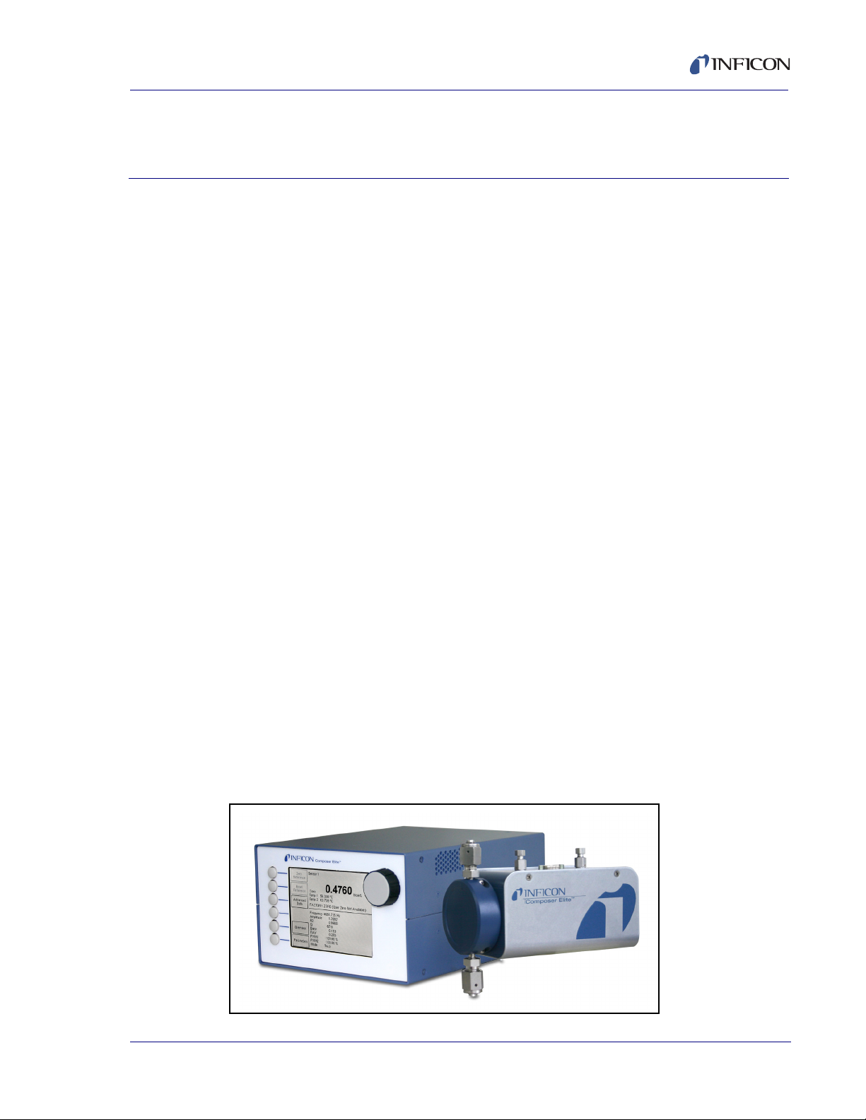
1.1.1 Description of the Composer Elite System
The Composer Elite System consists of:
A Sensor Control Unit which sends/receives electrical signals to/from the
Acoustic Sensor. The Sensor Control Unit provides an LCD display and
interface for user interaction (see Figure 1-1).
An Acoustic Sensor which interfaces to the process gas tubing and forms the
physical basis for the speed of sound measurement (see Figure 1-1). Two
versions of Acoustic Sensor are available:
Chapter 1
Introduction
Standard Acoustic Sensor, for use with hydrogen or helium carrier gas at
flow rates up to 2000 sccm, or for carrier gases of any molecular weight at
flow rates up to 1000 sccm.
High Flow Acoustic Sensor, for use with nitrogen carrier gas or a higher
molecular weight carrier gas, at flow rates between 1000 and 2000 sccm.
An Interconnect Cable which connects the Sensor Control Unit and
Acoustic Sensor.
An optional 24 V(dc) Power Supply which provides power to the
Sensor Control Unit.
Windows
setup through RS-232C or DeviceNet. See Chapter 6, Composer Elite
PN 074-566-P1B
Multi-Sensor Software.
Figure 1-1 Sensor control unit (left), acoustic sensor (right)
®
Composer Elite Multi-Sensor Software, for system operation and
1 - 1
Page 16
Composer Elite Operating Manual
CAUTION
WARNING
WARNING - Risk Of Electric Shock
1.2 Using this Manual
Please take a moment to read the following.
1.2.1 Symbols and their Definitions
NOTE: Notes provide additional information about the current topic.
HINT: Hints provide insight into product usage.
Failure to heed these messages could result in a
malfunction or damage to Composer Elite.
Failure to heed these messages could result in
physical injury.
Dangerous voltages are present which could result in
personal injury.
PN 074-566-P1B
1 - 2
Page 17
1.2.2 General Cautions and Warnings
WARNING - Risk Of Electric Shock
CAUTION
CAUTION
WARNING
WARNING
Dangerous voltages are present inside the 24 V power
supply whenever the power cord is connected. Do not
open the power supply casing.
Composer Elite contains circuitry susceptible to
transient mains voltages. Disconnect the power cord
whenever making any interface connections.
Composer Elite Operating Manual
Do not open the casing of any component of the
Composer Elite System. There are no user-serviceable
components inside. Refer all maintenance to qualified
INFICON personnel.
Do not install or use Composer Elite in a manner
inconsistent with the instructions in this operating
manual. Failure to do so may result in damage to the
instrument or personal injury.
PN 074-566-P1B
Many of the precursor gases that can be used with
Composer Elite are toxic. Refer to the material's Material
Safety Data Sheet for information regarding personal
safety.
1 - 3
Page 18

Composer Elite Operating Manual
1.3 How To Contact INFICON
Worldwide customer support information is available under Contact >> Support
Worldwide at www.inficon.com
Sales and Customer Service
Technical Support
Repair Service
If you are experiencing a problem with your Composer Elite or Composer Elite
Multi-Sensor software, please have the following information readily available:
The Sales Order or PO number for the Composer Elite purchase.
The version of the software if you are calling about Composer Elite
Multi-Sensor software.
A description of the problem.
An explanation of any corrective action that you may have already attempted.
The exact wording of any error messages that you may have received.
1.3.1 Returning Your Composer Elite
Do not return any component of your Composer Elite System to INFICON without
first speaking with a Customer Support Representative. You must obtain a Return
Material Authorization (RMA) number from the Customer Support Representative.
If you deliver a package to INFICON without an RMA number, your package will be
held and you will be contacted. This will result in delays in servicing your
Composer Elite.
Prior to being given an RMA number, you will be required to complete a Declaration
Of Contamination (DoC) form if your Acoustic Sensor is being returned. DoC forms
must be approved by INFICON before an RMA number is issued. INFICON may
require that the Acoustic Sensor be sent to a designated decontamination facility,
not to the factory.
PN 074-566-P1B
1 - 4
Page 19

1.4 Unpacking and Inspection
1 If Composer Elite has not been removed from its shipping container, do so now.
Do not discard the packing materials before reading the following steps.
2 Carefully examine Composer Elite for damage that may have occurred during
shipping. This is especially important if you notice obvious rough handling on
the outside of the container. Immediately report any damage
to the carrier and to INFICON.
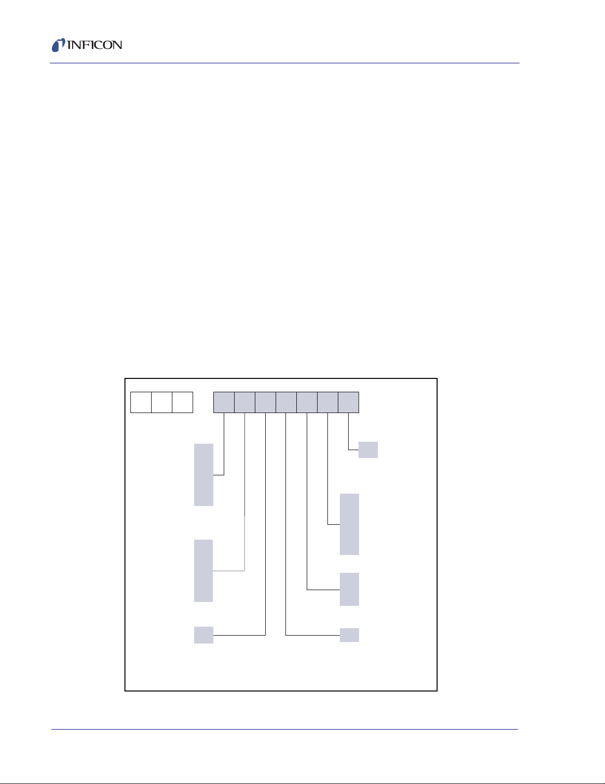
3 Take an inventory of your order by referring to the configuration code in your
order invoice and the information shown in section 1.4.1 and Figure 1-2.
4 Perform a power-up verification of the Sensor Control Unit. (See section 1.4.2.)
5 For additional information or technical assistance, contact INFICON
(Refer to section 1.3).
Composer Elite Operating Manual
PN 074-566-P1B
1 - 5
Page 20
Composer Elite Operating Manual
CPE–
0
1
2
3
4
5
N
0
1
2
3
4
5
0
Number of Standard
Acoustic Sensors
SEE NOTE 1
None
1
2
3
4
5
Number of High Flow
Acoustic Sensors
SEE NOTE 2
None
1
2
3
4
5
Expansion Option
Not Currently Available
None
0
1
2
0
Expansion Option
Not Currently
Available
None
Quantity of 4.6 m (15 ft.)
Acoustic Sensor Cables
None
One 4.6 m (15 ft.) cable
Two 4.6 m (15 ft.) cables
Three 4.6 m (15 ft.) cables
Four 4.6 m (15 ft.) cables
Five 4.6 m (15 ft.) cables
Optional Power Supply
None
115 V
230 V
0
1
2
3
4
5
NOTE 1:
The Standard Acoustic Sensor is for use with H
2
or He carrier
gas at flow rates of 0 to 2000 sccm OR for any molecular
weight carrier gas when flow rates are 1000 sccm or less
Expansion Option
Not Currently Available
None
Note 2:
For use when the carrier gas molecular weight is 28 or
higher AND flow rates are between 1000 and 2000 sccm.
Not for use with any carrier gas molecular weight when flow
rates are below 1000 sccm.
1.4.1 Parts and Options Overview
Sensor Control Unit . . . . . . . . . . . . . . . . . . . . . . PN 761-220-G1
Acoustic Sensor
Standard . . . . . . . . . . . . . . . . . . . . . . . . . . . . PN 761-219-G1
High Flow . . . . . . . . . . . . . . . . . . . . . . . . . . . PN 761-219-G2
NOTE: The High Flow Acoustic Sensor is identified by a "G2" marking
on the inlet tube nut.
Interconnect Cable, 15 ft. (4.6 m). . . . . . . . . . . . PN 600-1447-P15
Ship Kit. . . . . . . . . . . . . . . . . . . . . . . . . . . . . . . . PN 761-619-G1
Power Supply, 100-240 V(ac) (optional) . . . . . . PN 033-0056
Power Cord, 115 V (optional). . . . . . . . . . . . . . . PN 068-0433
Power Cord, 230 V (optional). . . . . . . . . . . . . . . PN 068-0434
Full Rack Extender (optional). . . . . . . . . . . . . . . PN 782-900-007
RS-232 Cable, 4.6 m (15 ft.) (optional) . . . . . . . PN 600-1001-P15
(contents: Leak Test Needle Kit;
operating manual and
Multi-Sensor software on CD)
Figure 1-2 Composer Elite part number configuration
1 - 6
PN 074-566-P1B
Page 21

Composer Elite Operating Manual
1.4.2 Sensor Control Unit Power-Up Verification
It is not necessary to have Acoustic Sensors or communications cables connected
to the Sensor Control Unit at this time.
1 Set the power switch on the rear panel of the Sensor Control Unit to the 0 (OFF)
position. (See Figure 3-8 on page 3-14.)
2 Using the INFICON (optional) 24 V power supply, or a power supply as defined
in section 1.5.4 and Table 1-1 on page 1-12, insert the output cable of the 24 V
power supply into the connector labeled 150W 24V on the rear panel of the
Sensor Control Unit (see Figure 3-8 on page 3-14). Make certain the cable is
inserted until it locks in place.
3 Connect mains power (refer to section 1.5.4.2 on page 1-12)
to the input of the 24 V power supply.
4 Power up the Sensor Control Unit from the rear panel by setting the power
switch to the 1 (ON) position. The Boot screen will appear followed by a
System Overview screen.
4a Verify that the information displayed on the Boot screen is as described by
section 3.3.2.1 on page 3-5.
4b Verify that the System Overview screen (see section 3.3.2.4 on page 3-8)
appears after the Boot screen.
5 If the information displayed on the Boot screen is not as described by section
3.3.2.1, or if the System Overview screen does not appear, contact INFICON.
6 Power down the Sensor Control Unit by setting the power switch to the
0 (OFF) position.
PN 074-566-P1B
1 - 7
Page 22

Composer Elite Operating Manual
1.5 Specifications
1.5.1 Composer Elite System Operating Specifications
Operating Pressure Range . . . . . . . 26.7 to 133.4, kPa [200-1000 Torr] absolute
Routine Overpressure Rating. . . . . . Up to 202.7 kPa [1520 Torr] absolute
Maximum Overpressure. . . . . . . . . . 826.2 kPa [6200 Torr] absolute.
Pressure over 826.2 kPa may damage
Acoustic Sensor diaphragms.
Gas Flow Range
Standard Acoustic Sensor
(for H2 and He carrier gas). . . . . 0 to 2000 sccm,
pressure drop at 2000 sccm flow is
approximately 12 Torr [1.60 kPa] at standard
temperature and pressure
High Flow Acoustic Sensor
(for N2 carrier gas or
higher molecular weight) . . . . . . 1000 to 2000 sccm,
pressure drop at 2000 sccm flow is
approximately 6 Torr [0.80 kPa] at standard
temperature and pressure.
Measurement Stability . . . . . . . . . . . 1 hour drift: +/- 0.032 Hz after 1 hour
stabilization (equivalent to +/- 2.5 ppm
Cp2Mg in N
). 8 hour drift: +/- 0.025 Hz after
2
2 hour stabilization
Determined using a N
carrier gas at
2
60°C, 800 Torr, 100 sccm flow
Measurement Rate. . . . . . . . . . . . . . 1 second
Concentration Reproducibility . . . . . <3 x 10⁻⁶ molar TMIn equivalent in H
[<2.4 x 10⁻⁵ molar TMIn equivalent in N
2
2
Sensitivity . . . . . . . . . . . . . . . . . . . . . Carrier at 60°C, 800 Torr, 100 sccm flow,
0.00011% of TMIn in H
in N
]
2
[0.0008% of TMIn
2
Time to Operation from
Room Temperature . . . . . . . . . . . . . For five Acoustic Sensors from ambient
temperature to the "at temperature" condition
is 120 minutes. Three or fewer sensors
typically require 90 minutes or less.
Reliability and Serviceability. . . . . . . Mean Time Between Failure: >8000 hours
]
PN 074-566-P1B
1 - 8
Page 23

Composer Elite Operating Manual
1.5.2 Composer Elite Sensor Control Unit
Size H x W x D . . . . . . . . . . . . . . . . . 132.8 x 213.4 x 254 mm
Measurement Channels . . . . . . . . . . Up to 5 Acoustic Sensors supported with
Required Connector Clearance . . . . 76.2 mm (3 in.) at rear panel for electrical
Rack Mount . . . . . . . . . . . . . . . . . . . Optional;
Weight . . . . . . . . . . . . . . . . . . . . . . . Approximately 3.0 kg (6.6 lb.)
Operating Temperature Range. . . . . 20 to +50°C (68 to 122°F)
Storage Temperature Range . . . . . . -10 to +70°C (14 to 158°F)
Humidity Range . . . . . . . . . . . . . . . . 0 to 80% RH non-condensing
Power Switch . . . . . . . . . . . . . . . . . . Rear panel mounted circuit breaker
(5.23 x 8.4 x 10.0 in.)
3U Half Rack
1 Sensor Control Unit
connector removal or insertion
Full Rack Extender, PN 782-900-007
rated at 7.5 A
Power Requirements . . . . . . . . . . . . 24 V(dc), 150 watts
Display . . . . . . . . . . . . . . . . . . . . . . . TFT LCD
Front Panel Keys . . . . . . . . . . . . . . . Six buttons for screen selection
Control Knob . . . . . . . . . . . . . . . . . . For parameter selection and editing
Rotate for parameter selection.
Rear Panel Connectors . . . . . . . . . . Ground stud, power connection, 15-pin
high-density D-sub connectors to sensor
cards, 9-pin D-sub connector for RS-232C
and M12x1 round connector for DeviceNet
communications
PN 074-566-P1B
Cleaning . . . . . . . . . . . . . . . . . . . . . . The casing can be safely cleaned with a mild
detergent or spray cleaner designed for that
purpose. Care should be taken to prevent
any cleaner from entering the unit
Regulatory Compliance . . . . . . . . . . Certified to CE standards, RoHS compliant,
& compliant to DeviceNet standards
Interconnect Cable . . . . . . . . . . . . . . 4.6 m (15 ft.) length, 15-pin high-density
D-sub connector on each end
1 - 9
Page 24

Composer Elite Operating Manual
1.5.3 Acoustic Sensor
Size . . . . . . . . . . . . . . . . . . . . . . . . . 124 mm (4.88 in.) between VCR-4 seal
Measurement Principle . . . . . . . . . . Precursor concentration determined by
Materials in Contact with Process Gas
Sensor Body. . . . . . . . . . . . . . . . 316L Stainless Steel
Tubing . . . . . . . . . . . . . . . . . . . . Seamless 316L SS and automatic butt weld
Isolation Diaphragms . . . . . . . . . 0.017 mm (0.00067 in.) Inconel
surfaces. Maximum outline dimensions
W x H x D (with gaskets and caps)
77.7 x 149.9 x 185.4 mm
(3.06 x 5.90 x 7.30 in.)
precision measurement of speed of sound in
a temperature controlled volume.
Measurement quality is enhanced by a
multi-chamber Helmholtz type resonator
fittings
®
X-750,
sealed with Inconel 718 gold plated c-rings
Connection to Process
®
Gas System . . . . . . . . . . . . . . . . . . . Swagelok
VCR®-4 male; inlet and outlet
inline 124 mm (4.88 in.) seal face to seal
face, near zero clearance required
Leak Test Service
Port Connection . . . . . . . . . . . . . . . . Swagelok VCR-2 female
Swept Volume . . . . . . . . . . . . . . . . . Resonant chamber: 8.9 cc
Connecting Inlet and Outlet tubes
(combined volume): 3.7 cc
Total Swept Volume . . . . . . . . . . 12.6 cc
Operating Temperature Range. . . . . 5°C minimum above ambient, range 30°C to
65°C, heat mode only
-9
Maximum Leak Rate . . . . . . . . . . . . 1x10
cm3/s helium
Electrical Connection . . . . . . . . . . . . 15-pin high-density D-sub
to Sensor Control Unit
Required Connector Clearance . . . . Required clearance 76.2 mm (3 in.) one side
for electrical connector removal or insertion
PN 074-566-P1B
1 - 10
Page 25

Mounting Requirements . . . . . . . . . . M4-0.7 (4), max. screw penetration 6.4 mm
WARNING - Risk Of Electric Shock
Weight . . . . . . . . . . . . . . . . . . . . . . . Approximately 2.3 kg (5.1 lb.)
Storage Temperature Range . . . . . . -10 to +70°C (14 to 158°F)
Humidity Range . . . . . . . . . . . . . . . . 0 to 80% RH non-condensing
1.5.4 Power Supply
The following sections detail the electrical power specifications for the optional
Power Supply. A universal input power supply converts local mains voltage to
regulated and current limited 24 V(dc) for powering the Sensor Control Unit.
Composer Elite Operating Manual
(0.25 in.) depth threaded holes provided.
Because the attachment to each system
widely varies, a mounting bracket must be
customer fabricated.
Failure to comply with the electrical power requirements
stated below may result in Composer Elite
malfunctioning or being damaged, and could result in
personal bodily injury.
1.5.4.1 Rated Output
Voltage . . . . . . . . . . . . . . . . . . . . . . . 24 V(dc) +5% / -2%
Ripple and Noise . . . . . . . . . . . . . . . 480 mV peak-to-peak max.
Current . . . . . . . . . . . . . . . . . . . . . . . 6.25 A max.
Short Circuit Protection . . . . . . . . . . Continuous, hiccup mode
24 V Connector Interface . . . . . . . . . Shielded Cable Assembly
PN 074-566-P1B
Connector . . . . . . . . . . . . . . . . . . 4-pin, Kycon KPPx-4P or equiv.
Length. . . . . . . . . . . . . . . . . . . . . 1830 mm
Wiring Size . . . . . . . . . . . . . . . . . #14 AWG
+24 V. . . . . . . . . . . . . . . . . Pins 3, 4
Gnd . . . . . . . . . . . . . . . . . . Pins 1, 2
Shield Drain. . . . . . . . . . . . Shell
Shell . . . . . . . . . . . . . . . . . Grounded
1 - 11
Page 26
Composer Elite Operating Manual
Pin 1
D.W. (GND)
Pin 2
(GND)
Pin 3
White (+V
o
)
D.W. (GND)
Pin 4
(+V
o
)
4 P POWER DIN
1.5.4.2 Rated Input
Operational Voltage Range . . . . . . . 100 to 240 V (ac) +/- 10% (ac)
Frequency Range. . . . . . . . . . . . . . . 47 to 63 Hz
In-rush Current . . . . . . . . . . . . . . . . . <60 A at 230 V(ac) input,
25°C ambient cold start
Input Current . . . . . . . . . . . . . . . . . . 2.5 A max.
Overvoltage . . . . . . . . . . . . . . . . . . . 110% - 130% of nominal
(Cycle input power to reset)
Unit Mains Connector. . . . . . . . . . . . IEC320-C14 (Accepts IEC 320-C13)
1.5.4.3 Power Supply Environmental Specifications
Operating Temperature . . . . . . . . . . 0 to +40°C
Storage Temperature . . . . . . . . . . . . -10 to +70°C
Humidity . . . . . . . . . . . . . . . . . . . . . . 20 to 90% non-condensing
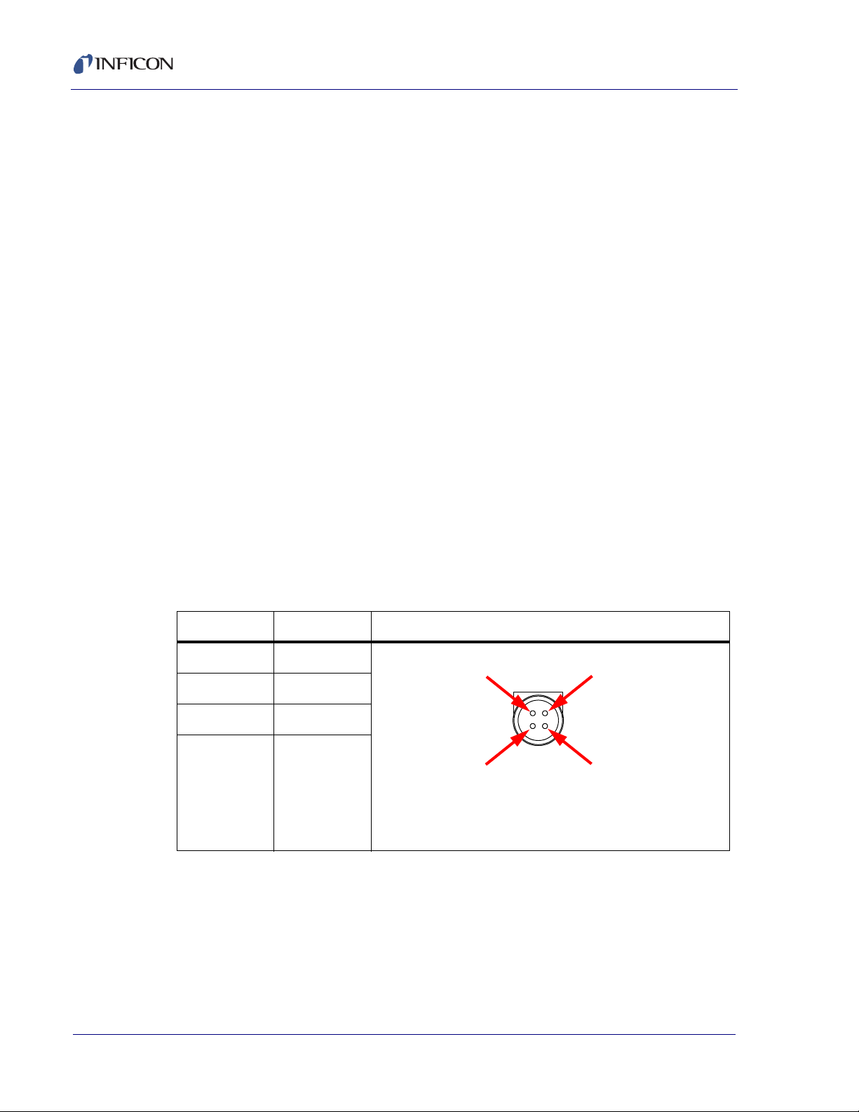
1.5.5 User Supplied Power Supply
If the user provides their own power supply, it must conform to the specifications
and requirements indicated by section 1.5.4. The power supply output cable must
be wired to a 4-pin connector as shown in Table 1-1.
Table 1-1 +24 Volt power connector’s pin diagram
Pin Function Wiring Diagram for Kycon KPPx-45 Plug
1 Gnd
2 Gnd
3 +24 V
4 +24 V
PN 074-566-P1B
1 - 12
Page 27

Composer Elite Operating Manual
1.5.6 Computer Requirements for Composer Elite Multi-Sensor Software
Processor . . . . . . . . . . . . . . . . . . . . . 1 GHz
Memory . . . . . . . . . . . . . . . . . . . . . . 512 MB RAM
Display Resolution . . . . . . . . . . . . . . 1280 x 1024
Storage. . . . . . . . . . . . . . . . . . . . . . . 5 MB of Hard Drive Space
Operating System. . . . . . . . . . . . . . . Windows XP (SP3), Windows 7
Communications. . . . . . . . . . . . . . . . RS-232 Serial Port, or USB-Serial Adapter,
or DeviceNet Card
Other . . . . . . . . . . . . . . . . . . . . . . . . Microsoft
®
.Net Framework 4 Client Profile
(x86 and x64)
1.5.7 DeviceNet Requirements for Composer Elite Multi-Sensor Software
Interface Card. . . . . . . . . . . . . . . . . . Beckhoff FC5201 DeviceNet Interface Card
Connectivity . . . . . . . . . . . . . . . . . . . 1-Channel, PCI bus
Software . . . . . . . . . . . . . . . . . . . . . . Beckhoff TwinCAT I/O
Power . . . . . . . . . . . . . . . . . . . . . . . . 24 V(dc), external power supply
NOTE: These requirements do not apply when DeviceNet is used in conjunction
with other software.
1.5.8 Mounting Requirements
The Sensor Control Unit is designed for bench-top operation or mounting in a
standard 48.26 (19 in.) rack using the optional Full Rack Extender
(PN 782-900-007). The Sensor Control Unit occupies half the width of a
standard rack, so a blank-off is provided with the optional Full Rack Extender.
The Acoustic Sensor must be attached to a rigid mounting surface using the
PN 074-566-P1B
M4 threaded holes in the Acoustic Sensor cover. Maximum depth of screw
penetration into M4 mounting holes is 6.4 mm (0.25 in.).
Dimension from VCR-4 gland-to-gland is 12.4 cm (4.88 in.).
1.5.9 Ventilation Requirements
The Sensor Control Unit is adequately ventilated when operating on a bench
top or when installed in a standard 48.26 cm (19 in.) rack using the optional
Full Rack Extender (PN 782-900-007).
The Acoustic Sensor does not require ventilation.
1 - 13
Page 28

Composer Elite Operating Manual
1.5.10 Perimeter for Maintenance Access
Acoustic Sensor to be removed from the process gas tubing (Swagelok VCR-4
fittings) require side-to-side or top-to-bottom clearance of 16 cm (6 in.)
for wrench rotation.
Interconnect Cable to be removed or replaced from either Acoustic Sensor or
Sensor Control Unit requires 8 cm (3 in.) clearance.
Sensor Control Unit to be removed from rack, full 30.5 cm (12 in.)
length required.
1.5.11 Environmental Requirements
The following detail Composer Elite environmental requirements.
Operation . . . . . . . . . . . . . . . . . . . . . Composer Elite is designed for
Altitude Range . . . . . . . . . . . . . . . . . Composer Elite can be used to a maximum
indoor use only.
altitude of 2000 m (6561 ft.).
For applications above this altitude, please
contact INFICON.
Maximum Humidity. . . . . . . . . . . . . . Non-condensing relative humidity at
operating temperature.
Pollution Degree. . . . . . . . . . . . . . . . Category II (as defined by EN61010-1, only
non-conductive pollution occurs).
Operating Temperature . . . . . . . . . . Refer to section 1.5,
Specifications, on page 1-8.
PN 074-566-P1B
1 - 14
Page 29

Composer Elite Operating Manual
CAUTION
2.1 Composer Elite Installation Guidelines
The requirements and recommendations in section 2.1.1, section 2.1.2, and
section 2.1.3 must be reviewed and understood before Composer Elite is installed
as described by section 2.2, Composer Elite Installation, on page 2-8.
2.1.1 Pressure, Temperature, and Tubing
2.1.1.1 Maximum Pressure
Reliable measurement of concentration to absolute pressures as low as 26.66 kPa
(200 Torr) requires relatively thin and flexible diaphragms to be used so that
sufficient acoustic energy may be transmitted.
There is a possibility that the diaphragms may destructively rupture if an absolute
pressure greater than 826 kPa (6200 Torr) is applied. A secondary containment
chamber is built into the Acoustic Sensor to prevent process gases from escaping
the Acoustic Sensor in the event of a diaphragm rupture.
Chapter 2
Installation
Do not connect the Acoustic Sensor to process tubing
that can exceed an absolute pressure of
826 kPa (6200 Torr). Exposing the Acoustic Sensor to
excess pressure may cause catastrophic diaphragm
failure or may stretch the diaphragms, requiring on-site
reference zeroing (see section 4.1.2 on page 4-1).
A certified rupture disk should be installed upstream of
PN 074-566-P1B
the Acoustic Sensor to limit any possible over-pressure
to less than 826 kPa (6200 Torr).
2 - 1
Page 30

Composer Elite Operating Manual
2.1.1.2 Pressure and Tubing Size
The Composer Elite System is designed to operate with the gases in the Reactor's
process tubing at a pressure of 26.66 to 133.3 kPa (200 to 1000 Torr). The inner
diameter of the inlet and outlet tubes on the Standard and High Flow Acoustic
Sensors were designed to optimize performance at low pressures; however, the
Reactor’s process tubing may be of any appropriate size without degrading
Composer Elite performance.
2.1.1.3 Heated Process Tubing and Acoustic Sensor Temperatures
Operation of the Acoustic Sensor at a temperature slightly higher than the process
gas tubing will help prevent material from condensing inside the acoustic sensor.
INFICON recommends the following temperature settings:
The Temperature Setpoint 1 setting for the Acoustic Sensor's resonant
chamber temperature should be 5°C or more above ambient temperature.
See section 3.3.2.7, Sensor Parameters Screen, on page 3-12.
The Temperature Setpoint 2 setting for the Acoustic Sensor's inlet tube
temperature should be above the Temperature Setpoint 1 setting. Typically
start out with this temperature three degrees above Temperature Setpoint 1.
The inlet tube heater is designed to minimize zero point offset caused by large
flow rate changes. The optimal setting will depend on process conditions.
See section 3.3.2.7, Sensor Parameters Screen, on page 3-12.
2 - 2
PN 074-566-P1B
Page 31

2.1.2 Grounding and Shielding
WARNING - Risk Of Electric Shock
CAUTION
2.1.2.1 Power Supply Grounding Requirement
The Composer Elite 24 V Power Supply must be
connected to a grounded socket outlet using a
three-conductor power cable with ground terminal.
The Composer Elite 24 V power supply (optional) is connected to ground through
a sealed three-conductor power cable, which must be plugged into a socket outlet
with a protective ground terminal. Extension cables must always have three
conductors including a protective ground terminal.
2.1.2.2 Earth Ground Requirement
Composer Elite Operating Manual
A low impedance and reliable earth ground is required for
proper performance of Composer Elite.
If local facilities engineering cannot provide a low impedance earth ground close to
Composer Elite, the following procedure is recommended.
1 Where soil conditions allow, drive two 3 m (10 ft.) copper clad steel rods into
the ground 2 m (6 ft.) apart.
2 Pour a copper sulfate or other salt solution around the rods to improve
the soil’s conductivity.
A near zero resistance measurement between the two rods indicates that a
desirable earth ground is established. In severe cases, it may take several
soakings of solution over several days to reach this condition.
PN 074-566-P1B
NOTE: Keep connections to this grounding network as short as possible. Most
noise transients contain significant power at high frequencies. A long path
adds to the ground circuit's inductance and thereby increases its
impedance at these frequencies.
2 - 3
Page 32

Composer Elite Operating Manual
CAUTION
Sensor Control Unit
Ground
Stud
Earth Ground
Acoustic Sensor
Reactor
Grounded
Copper Straps
Process
Tub ing
Grounded
Mounting
Surface
2.1.2.3 Composer Elite System Grounding Requirement
The Sensor Control Unit and Acoustic Sensor must be
grounded for proper performance of Composer Elite.
The following grounding method is recommended:
1 Verify that the Reactor is connected to a good, reliable earth ground (refer to
section 2.1.2.2, Earth Ground Requirement, on page 2-3). Use a solid copper
strap, at least 0.08 cm (0.030 in.) thick by 2.5 cm (1 in.) wide, and as short as
practical, for the connection between Reactor and earth ground (see
Figure 2-1).
2 Use a solid copper strap, approximately 0.08 cm (0.030 in.) thick by
2.5 cm (1 in.) wide, and as short as practical, between the Sensor Control Unit
ground stud (see Figure 2-1) and the Reactor. A ring terminal soldered to the
ground strap will allow for a good connection to the ground stud and convenient
removal or installation.
3 Connect the Acoustic Sensor to earth ground by one or both of the
3a Use the M4 mounting holes provided on the Acoustic Sensor to attach the
3b Connect the Acoustic Sensor's outlet tubing to process tubing that is connected
following methods:
Acoustic Sensor to a metal mounting surface that is connected to earth ground
(see Figure 2-1 and section 2.2.2 on page 2-9).
or
to earth ground (see Figure 2-1 and section 2.2.2 on page 2-9).
Figure 2-1 System grounding diagram
PN 074-566-P1B
2 - 4
Page 33

2.1.2.4 Electrical Interference Reduction
When Composer Elite is integrated into a deposition system, each cable
connection is a potential path for electrical noise to be conducted to the Sensor
Control Unit or Acoustic Sensor. The possibility of external electrical interference
problems can be greatly reduced by adhering to the following guidelines:
Make certain the Sensor Control Unit and Acoustic Sensor are properly
grounded. (Refer to section 2.1.2.3, Composer Elite System Grounding
Requirement, on page 2-4.)
Make certain the Sensor Control Unit covers and option panels are in place and
secured with the provided fasteners.
Use shielded cable as short as practical for remote communications.
Avoid routing the Composer Elite Interconnect cable and communications
cable near areas that have the potential to generate high levels of electrical
interference. For example, large power supplies can be a source of large and
rapidly changing electromagnetic fields. Placing cables at least 30 cm (1 ft.)
from these problem areas can result in a significant reduction
of electrical interference.
Composer Elite Operating Manual
PN 074-566-P1B
2 - 5
Page 34

Composer Elite Operating Manual
Mains
Power
Optional
Power
Supply
24 V(dc)
RS-232
Sensor
Control
Unit
DeviceNet
Interconnect
Cable
Carrier Gas
P
MFC MFC
Bubbler
Dilution Flow
Inlet
Acoustic Sensor
Located downstream
Outlet
Back
Pressure
Controller
Reactor
MFC (Mass Flow Controller)
from Dilution Flow
2.1.3 Composer Elite Location Selection
2.1.3.1 Selecting The Acoustic Sensor Location
Locate the Acoustic Sensor at a point after the Dilution Flow gas is added and
before the Back Pressure Controller. (See Figure 2-2 on page 2-6.) This creates
the environment with the most stable pressure and flow conditions for best
Composer Elite stability. Positioning the Acoustic Sensor after the Dilution Flow
also simplifies calibration by making it easy to flow pure carrier gas through the
Acoustic Sensor to set the Reference Zero.
Figure 2-2 Basic integration with a reactor
2 - 6
The Acoustic Sensor may be installed in any orientation, however, INFICON
recommends the normal inlet and outlet tube convention (refer to Figure 2-2) be
followed. The inlet tube is substantially longer than the outlet tube to facilitate
temperature equalization. If the inlet and outlet tube connections are reversed,
there may be a small frequency or concentration offset when the total gas flow
through the sensor is varied.
Ventilation clearance is not required; however, the surface the Acoustic Sensor is
mounted to must be at least 5°C below Temperature Setpoint 1.
The dimension from inlet tube VCR-4 sealing surface to outlet tube VCR-4 sealing
surface is 124 mm (4.88 in.).
Acoustic Sensor installation or removal from process tubing requires side-to-side
or top-to-bottom clearance of 152.4 mm (6 in.) for wrench rotation.
Interconnect Cable installation or removal requires 76.2 mm (3 in.) clearance.
PN 074-566-P1B
Page 35

Composer Elite Operating Manual
WARNING
The Interconnect Cable route should be planned to minimize external electrical
interference. (Refer to section 2.1.2.4, Electrical Interference Reduction, on page
2-5.)
2.1.3.2 Selecting The Sensor Control Unit Location
The Sensor Control Unit is designed for bench top operation or mounting in a
standard 48.26 cm (19 in.) rack using the optional Full Rack Extender
(PN 782-900-007). Ventilation is adequate when operating on a bench top or when
installed in a standard rack using the optional Full Rack Extender.
If the Sensor Control Unit will not be mounted in a
standard rack, select a location where the Sensor Control
Unit is protected against falling to prevent instrument
damage and personal injury.
Sensor Control Unit removal from a standard rack requires 30.5 cm (12 in.)
clearance in front of the rack.
Clearance of 7.62 cm (3 in.) is required at the rear of the Sensor Control Unit for
installation or removal of Interconnect, Power Supply, RS-232, and DeviceNet
cables.
Sensor Control Unit location should be selected to minimize the length of the
grounding strap. (Refer to section 2.1.2.3, Composer Elite System Grounding
Requirement, on page 2-4.)
Interconnect Cable and communication cable routes should be planned to
minimize external electrical interference. (Refer to section 2.1.2.4, Electrical
Interference Reduction, on page 2-5.)
PN 074-566-P1B
2 - 7
Page 36

Composer Elite Operating Manual
CAUTION
2.2 Composer Elite Installation
2.2.1 Installing The Sensor Control Unit in a 19 in. (48.26 cm) Rack
Install the Sensor Control Unit in a standard 48.26 (19 in.) rack using the optional
Full Rack Extender (PN 782-900-007).
1 Assemble the two 7.62 x 12.7 cm (3 x 5 in.) Extender Kit side panels and the
larger front and rear panels into a box configuration using the eight 6-32
flat-head screws.
2 Thread two 10-32 shoulder screws from the inside of one of the box sides until
the threads extend fully to the outside.
3 Attach the Extender Kit to the Sensor Control Unit by threading the shoulder
screws into the matching holes in the Sensor Control Unit covers.
4 Attach the rack mounting ears with the 10-32 flat-head screws provided.
5 Carefully lift the assembly into a full width, 13.33 cm (5-1/4 in.) high rack space.
6 Attach the assembly to the rack using the necessary screws (not provided).
7 Connect the Sensor Control Unit to earth ground as described by section
2.1.2.3, Composer Elite System Grounding Requirement, on page 2-4.
Connect the Sensor Control Unit to earth ground as
described by section 2.1.2.3, Composer Elite System
Grounding Requirement, on page 2-4.
PN 074-566-P1B
2 - 8
Page 37

2.2.2 Installing The Acoustic Sensor
WARNING
CAUTION
CAUTION
CAUTION
Many gases used for film growth are toxic at very low
exposure levels.
Although the Acoustic Sensor was thoroughly leak
tested at the factory, periodic leak testing of the Acoustic
Sensor is recommended. See section 7.2, Leak Test
Procedures, on page 7-1.
1 Remove the caps from the VCR-4 fittings on the Acoustic Sensor's inlet and
outlet tubes by holding the fitting stationary with a 5/8 in. wrench while turning
the cap counterclockwise with a 3/4 in. wrench. Do not discard the caps.
Composer Elite Operating Manual
2 Remove and discard the gaskets from the VCR-4 fittings.
3 Mount the Acoustic Sensor securely to a rigid surface, using the four holes with
M4 thread, to prevent stress at the inlet and outlet tubing welds and seals. See
Figure 2-3 and Figure C-2 on page C-3.
Do not use the inlet and outlet tubing to support the
weight of the Acoustic Sensor.
PN 074-566-P1B
Figure 2-3 M4 mounting holes
Maximum allowable depth of screw penetration into the
M4 mounting holes is 6.4 mm (0.25 in.).
2 - 9
Page 38

Composer Elite Operating Manual
CAUTION
4 Install new VCR-4 gaskets (see section 7.3, Spare Parts, on page 7-5) into the
VCR fittings on the inlet and outlet tubes.
NOTE: Gaskets with retainers are directional and easily snap over the face of
the gland seal. (See Figure 2-4.)
Figure 2-4 Installation of gasket with retainer on gland
5 Connect the Acoustic Sensor to the process tubing using a 5/8 in. wrench to
tighten the VCR fittings on the inlet and outlet tubes while holding the VCR
fittings on the process tubing stationary with a wrench.
NOTE: Swagelok recommends tightening VCR type fittings 1/8 turn past
finger-tight for nickel and stainless steel gaskets.
Verify that the Acoustic Sensor is connected to earth
ground as described by section 2.1.2.3,
Composer Elite System Grounding Requirement, on
page 2-4.
PN 074-566-P1B
2 - 10
Page 39

Composer Elite Operating Manual
CAUTION
CAUTION
Power
Connector
Power
Switch
Ground
Stud
Sensor Card
Connector
DeviceNet
Connector
RS-232
Connector
2.2.3 Installing Interconnect, Power Supply, and Communications Cables
1 Set the Sensor Control Unit power switch to 0 (OFF). (See Figure 2-5.)
Composer Elite contains circuitry susceptible to
transient mains voltages. Make certain Composer Elite is
powered down whenever making any interface
connections.
Figure 2-5 Sensor control unit connections
PN 074-566-P1B
2 Connect the Interconnect Cable(s) male D-sub connector to the Sensor card(s)
connector. (Refer to Figure 2-5.) Tighten the thumb screws on the cable
connector to secure the cable to the Sensor card.
Make certain the Interconnect Cable D-sub connectors
are correctly oriented with the Sensor card / Acoustic
Sensor connectors to avoid damaging connector pins.
3 Connect the Interconnect Cable(s) female D-sub connector to the Acoustic
Sensor(s) connector. Tighten the thumb screws on the cable connector to
secure the cable to the Acoustic Sensor.
4 If applicable, connect the RS-232 cable to the Control card RS-232 connector,
or connect the DeviceNet cable to the Control card DeviceNet connector.
(Refer to Figure 2-5.)
2 - 11
Page 40

Composer Elite Operating Manual
5 Insert the 24 V Power Supply output-cable connector into the Sensor Control
Unit power connector until it locks in place. (Refer to Figure 2-5.)
6 Connect the power cord to the 24 V Power Supply inlet receptacle.
7 Connect the power cord plug to Mains power. (Refer to section 1.5.4.2, Rated
Input, on page 1-12.)
2.2.4 Installing Composer Elite Multi-Sensor Software
See section Chapter 6, Composer Elite Multi-Sensor Software, on page 6-1.
2 - 12
PN 074-566-P1B
Page 41

3.1 Initialization and Setup
1
2
3
4
5
6
7
Application-specific parameter values must be entered, or downloaded, to
Composer Elite. The parameters include the gases’ Specific Heat Ratios and
Molecular Weights.
3.1.1 Parameter Entry
Parameter values may be downloaded to Composer Elite by:
Composer Elite Multi-Sensor Software, see Chapter 6.
Remote communications using the protocol and commands in Chapter 5.
Composer Elite front panel.
Composer Elite Operating Manual
Chapter 3
Operation
3.1.1.1 Composer Elite Front Panel Parameter Entry
Composer Elite front panel parameter entry uses buttons 1 - 6 and the
Control Knob (7) shown in Figure 3-1. The function of the buttons vary, depending
on the screen displayed and parameter highlighted.
Figure 3-1 Front panel buttons
PN 074-566-P1B
When viewing editable parameters, Edit is available. Position the cursor on the
parameter to edit by rotating the control knob. Press Edit to change parameter
values. The left-most digit of the numerical parameter being edited will now be
highlighted in red. Use Next and Prev to highlight the digit to edit, then rotate the
3 - 1
Page 42

Composer Elite Operating Manual
control knob to change the value for that digit. To save the changes, press Save.
To cancel changes, press Cancel. See Figure 3-2 for an example of screen layout
while editing parameters.
Figure 3-2 Editing parameters
3.2 Calibration
Calibration obtains the exact frequency (speed of sound) for the carrier gas (or one
component of a mixture) for specific Composer Elite System operating conditions.
Calibration determines Reference Zero.
For many applications, Factory Zero is sufficient to provide the needed levels of
accuracy and reproducibility. Refer to section 4.1.3, How is Performance Affected
if I Use the Factory (Reference) Zero Value?, on page 4-2.
3.2.1 Frequency of Calibration
Applications requiring the highest degree of reproducibility should be calibrated
daily. Experience will determine if less frequent calibrations are appropriate. See:
When and How Often to Set the Reference Zero, section 4.1.2 on page 4-1
How is Performance Affected if I Use the Factory (Reference) Zero Value?,
section 4.1.3 on page 4-2
What Happens if the Reference Zero is Improperly Set?, section 4.1.10 on
page 4-8
PN 074-566-P1B
3 - 2
Page 43

3.2.2 Special Tools and Materials
Flowing a pure gas through the Acoustic Sensor at process pressure and flow rate
is required for calibration.
NOTE: For guaranteed safe operation, a calibrated high-performance mass
spectrometer leak detector should be used to check leak integrity
whenever the Acoustic Sensor has been removed and reinstalled.
3.2.3 How to Calibrate
1 In the Sensor Parameters pane, set ALLOW USER ZERO to YES.
2 Flow calibration gas, usually pure carrier gas, through the Acoustic Sensor at
normal operating pressure and flow rate.
3 Allow sufficient time for the calibration gas to cleanse any mixed gases out of
the Resonant Chamber. The carrier gas has displaced all of the formerly
contained gas mixes when the concentration stops changing.
4 STEADY and AT TEMP indicators will be displayed to indicate that the
concentration and cell temperature are stable.
Composer Elite Operating Manual
5 Set the new Reference Zero value by
On Composer Elite Multi-Sensor Software, click Zero Reference
On the Composer Elite front panel, on the Sensor window, press Zero
Reference
6 The new Reference Zero is displayed on screens as User Zero.
3.2.4 How To Revert To Factory Default Settings
Factory Zero is re-established by changing any parameter value affecting
concentration measurement, such as Acoustic Sensor Setpoint 1 Temperature,
Specific Heat Ratio or Molecular Weight or by pressing Reset Reference on the
PN 074-566-P1B
Composer Elite front panel on individual Sensor screens.
Composer Elite may be reset to the default parameters by holding 1 and 6 down
while powering up the instrument. Data Reset will be displayed on the Boot screen
if this is successful. Parameters Reset will be displayed on the Errors and
Warnings screen.
3 - 3
Page 44

Composer Elite Operating Manual
CAUTION
3.3 How To Use Composer Elite
The following sections explain how to start, stop, and power down Composer Elite.
A description and purpose of the operating modes, displays, and system I/O
connectors is also provided.
3.3.1 How to Power Up and Power Down Composer Elite
Operating Composer Elite requires a 24 V power connection. Refer to section 1.5.4
on page 1-11 for complete power specifications.
To power up Composer Elite,
1 Connect the 24 V(dc) power supply
(see section 1.5.4, Power Supply, on page 1-11).
2 Set the ON/OFF (I|O) power switch on the rear panel of the Sensor Control Unit
in the ON (I) position (see Figure 3-8 on page 3-14).
To power down Composer Elite, set the rear panel of the Sensor Control Unit in the
ON (I) position in the OFF(0) position.
When powering down Composer Elite, make sure the
precursor gases are completely purged from the
Acoustic Sensor. When power is removed from the
Sensor Control Unit, the Acoustic Sensor temperature
will cool to room temperature. If precursor gases are not
completely purged, condensation of precursor gas inside
the Acoustic Sensor may occur as the Acoustic Sensor
cools down.
PN 074-566-P1B
3 - 4
Page 45

Composer Elite Operating Manual
3.3.2 Composer Elite Screen Descriptions
Boot Screen, see section 3.3.2.1
Indicators Displayed On Screens, see section 3.3.2.2 on page 3-6
Overview Screen, see section 3.3.2.3 on page 3-6
System Overview Screen, see section 3.3.2.4 on page 3-8
Errors and Warnings Screen, see section 3.3.2.5 on page 3-9
Sensor Screen, see section 3.3.2.6 on page 3-10
Sensor Parameters Screen, see section 3.3.2.7 on page 3-12
3.3.2.1 Boot Screen
During power-up of the Sensor Control Unit, the INFICON logo is displayed. The
following information is briefly displayed before the System Overview screen is
displayed:
Version x.xx.xx HW x (Control card firmware version and hardware version)
Loading....... Please Wait (while Data, Sensor, and DeviceNet statuses are
being determined) followed by Loading....... Complete
Data Wait followed by:
Data OK (if parameter values were retained in memory)
Data Reset (if memory was cleared to factory default parameter values;
refer to section 3.2.4 on page 3-3)
Parameter Error (contact INFICON if this message appears)
Sensor Data Error (contact INFICON if this message appears)
System Data Error (contact INFICON if this message appears)
Searching followed by:
PN 074-566-P1B
DeviceNet Detected (if a DeviceNet module is installed in the Control card)
DeviceNet Not Detected (if a DeviceNet module is not installed)
DeviceNet Error (if there is a problem with the DeviceNet module)
Initializing followed by:
Sensor n Detected (for installed Sensor cards)
Sensor n Not Present (for empty Sensor card slots)
Sensor n Initialization Failed (if there is a problem with a Sensor card)
3 - 5
Page 46

Composer Elite Operating Manual
CAUTION
3.3.2.2 Indicators Displayed On Screens
AT TEMP . . . . . . . . . . . . . . . . . . . . . Indicates that the temperature is within
NEAR TEMP . . . . . . . . . . . . . . . . . . Indicates that the current temperature is near
BELOW TEMP. . . . . . . . . . . . . . . . . Indicates that the current temperature is
ABOVE TEMP . . . . . . . . . . . . . . . . . Indicates that the temperature is higher than
STEADY. . . . . . . . . . . . . . . . . . . . . . Indicates that the concentration for the last
±0.002°C of Temperature Setpoint 1 and
±0.005°C of Temperature Setpoint 2.
The text is displayed in green.
the desired temperature for Temperature
Setpoint 1. The text is displayed in blue.
below the desired temperature for
Temperature Setpoint 1. The text is
displayed in orange.
the desired temperature for Temperature
Setpoint 1. The text is displayed in red.
seven measurements have an average error
less than 0.5 Hz and the drift is less than
twice the error. The text is displayed in green.
3.3.2.3 Overview Screen
Composer Elite will attempt to measure concentration and control Acoustic Sensor
temperatures to setpoints whenever it is powered up. It will give correct readings
when the pressure is within the specified range and correct values for the gases’
Molecular Weights and Specific Heat Ratios that have been entered (see Table B-1
on page B-1) and Factory Zero is used.
If a new Reference Zero is required, section 3.2.3, How to
Calibrate, on page 3-3 must be followed for establishing
Reference Zero with the correct pure calibration gas or
incorrect concentration values will be calculated.
The Overview screen displays each of the five available sensor channels,
displaying sensor Concentration (Conc) and Temperature 1 and 2 (Temp) for all
five sensors (see Figure 3-3). Unoccupied sensor slots are displayed in grey.
Temperature value will be displayed as 99.999 for cards that are installed with no
sensor attached.
Indicators (described above in section 3.3.2.2) display when appropriate.
PN 074-566-P1B
3 - 6
Concentration is displayed in Mole%.
Page 47

Composer Elite Operating Manual
ERRORS, WARNINGS, or ERRS & WRNS may be displayed, depending on
whether errors, warnings, or both are present (see section 3.3.2.5). If no errors or
warnings are present, this area will be blank.
Figure 3-3 Overview screen
Buttons 1 through 5 represent Sensor 1 Data, Sensor 2 Data, etc. To enlarge and
view data for an individual sensor, press the button associated with that sensor
number to enter the Sensor screen. For example, press Sensor 1 Data to view
data for sensor 1.
System will display the System Overview screen.
PN 074-566-P1B
3 - 7
Page 48

Composer Elite Operating Manual
3.3.2.4 System Overview Screen
The System Overview screen displays information about the system’s hardware.
It displays remote communication port information such as the DeviceNet address
and the RS-232 Baud rate. It also displays the firmware version, hardware version,
and the version number and status for any installed sensor cards.
Figure 3-4 System Overview screen
Press Edit to edit the DeviceNet address and the DeviceNet Baud Rate.
The DeviceNet address can be adjusted to values of 0-63, appropriate to the
network topology. The default value is 63.
The DeviceNet Baud Rate can be changed to 125, 250, or 500 Kbps.
The default value is 125.
NOTE: RS-232 baud rate cannot be changed. It is always 115200 baud.
Pressing Overview will display the Overview screen.
Pressing Errors & Warnings will display the Errors and Warnings screen.
PN 074-566-P1B
3 - 8
Page 49

3.3.2.5 Errors and Warnings Screen
The Errors and Warnings screen displays current hardware errors or warnings.
The error is listed with its sensor number (if applicable) and its error code. Use the
control knob to scroll through the list of errors and/or warnings. At the bottom of the
screen is a description of the highlighted error/warning. Details on system errors
and warnings can be found in Table 5-22 on page 5-32 and Table 5-23 on page
5-34. A total of twelve errors and twelve warnings can be simultaneously displayed.
If more than twelve errors or warnings are present, a second page will display the
remaining errors.
Figure 3-5 Errors and Warnings screen
Composer Elite Operating Manual
Pressing Clear COR Errs & Wrns (when available) will clear any COR (Clear On
Read) errors or warnings present. See Table 5-22 on page 5-32 and Table 5-23 on
page 5-34 for more information about COR errors and warnings.
PN 074-566-P1B
Use Next Page and Prev Page to navigate from page to page if there are more
than twelve errors or warnings listed.
Overview will display the Overview screen.
Back will navigate back to the System Overview screen.
3 - 9
Page 50

Composer Elite Operating Manual
3.3.2.6 Sensor Screen
On the Overview screen, press Sensor Data to display the Sensor screen (see
Figure 3-6). Data displayed on the Sensor screen is for an individual sensor. Data
includes Concentration (Conc), FACTORY ZERO status, Temp 1 and Temp 2.
Indicators (described in section 3.3.2.2 on page 3-6) display when appropriate.
Errors, Warnings or Errors & Warnings may be displayed, depending on
whether errors, warnings, or both are present. If no errors or warnings are present,
this area will remain blank.
Zero Reference, Reset Reference, Overview, Parameters, and Advanced Data
are available.
Figure 3-6 Sensor screen
3 - 10
During Calibration, pressing Zero Reference sets a new Zero Reference point.
Zero Reference is only available if the system meets the AT TEMP and STEADY
conditions and if ALLOW USER ZERO is set to YES on the Sensor Parameters
screen.
Reset Reference re-establishes the Factory Zero setting and is only available
when User Zero is displayed. Both buttons appear grey when they are
not available.
If Factory Zero is used, FACTORY ZERO is displayed.
If the sensor parameter ALLOW USER ZERO is set to NO, or if the Composer Elite
Sensor Control Unit is not connected to a Composer Elite Acoustic Sensor, (USER
ZERO NOT AVAILABLE) will be displayed next to FACTORY ZERO.
If a user-defined zero is being used, USER ZERO is displayed.
PN 074-566-P1B
Page 51

Composer Elite Operating Manual
Pressing Advanced Data displays acoustic information when a cell is attached.
This information displayed includes:
Frequency . . . . . . . . . . . . . . . . . Acoustic cell frequency.
Amplitude . . . . . . . . . . . . . . . . . Signal amplitude [Volts RMS] of the
measured frequency.
R2 . . . . . . . . . . . . . . . . . . . . . . . . Coefficient of Determination - Lorentzian
curve's "goodness of fit" (0<=R2<=1 where
1 is perfect curve fit).
Q. . . . . . . . . . . . . . . . . . . . . . . . . Resonant frequency's Quality Factor or
Q factor.
Error. . . . . . . . . . . . . . . . . . . . . . Lorentzian curve fit's Standard Error from
Acoustic Cell resonance points.
RAV . . . . . . . . . . . . . . . . . . . . . . Root Allen Variance frequency calculated
from 201 measurements.
PWM1. . . . . . . . . . . . . . . . . . . . . Power (Duty Cycle %) applied to cell heater.
PWM2. . . . . . . . . . . . . . . . . . . . . Power (Duty Cycle %) applied to (internal)
inlet tube heater.
Mode . . . . . . . . . . . . . . . . . . . . . Displays the sensor card’s current
measurement mode. Modes include Ready,
Baseline, Search, Track, and QTrack. See
Table 3-1 for descriptions of these modes.
Values for concentration will not be displayed
while in Ready, Baseline or Search mode.
On the Sensor screen, pressing Overview displays the Overview screen,
see section 3.3.2.3.
To view the Sensor Parameters screen for the sensor, press Parameters.
There is no direct way of moving from one Sensor screen to another. For example,
PN 074-566-P1B
to go from Sensor 1 to Sensor 2, exit to the Overview screen
and select Sensor 2 Data.
3 - 11
Page 52

Composer Elite Operating Manual
Table 3-1 Sensor card measurement modes
Mode Description
Ready Sensor card is not attempting to measure a resonance.
Baseline Acoustic signal level re-initialization is being performed before
Search mode is entered.
Search Sensor card is looking for an acoustic resonance to track/measure.
(Frequency, Amplitude, R2 and RAV should be ignored while in
Search mode.)
Track Sensor card is tracking/measuring a resonance.
QTrack Sensor card is tracking a resonance, but due to its rapid changes, the
higher slew rate QTrack is being used for measurement.
While in QTrack mode:
Frequency and amplitude will usually change rapidly
RAV will increase due to frequency change
R2 and Error should be ignored
3.3.2.7 Sensor Parameters Screen
The Sensor Parameters screen displays all available settings for a given sensor:
See Figure 3-7.
Figure 3-7 Sensor parameters screen
PN 074-566-P1B
3 - 12
Use the control knob to move between parameters, then press Edit to edit the
highlighted parameter. Refer to section 3.1.1 on page 3-1 for information on how to
enter and edit parameters. Overview displays the Overview screen. Back will
display the Sensor screen.
Page 53

Composer Elite Operating Manual
CAUTION
Allow user zero. . . . . . . . . . . . . . . . Is a user-defined reference zero allowed?
Default value is No.
Temperature Setpoint 1 . . . . . . . . . Sets the Acoustic Sensor’s resonant
chamber temperature (°C). Allowable range
is 30.0 to 65.0°C. Default is 40°C.
Temperature Setpoint 2 . . . . . . . . . Temperature setpoint (°C) of the inlet tube.
Allowable range is 30.0 to 68.0°C. Will
default to 3°C higher than Temperature
Setpoint 1 when Temperature Setpoint 1 is
updated.
Carrier MOL Weight . . . . . . . . . . . . Molecular weight of the lighter (or carrier)
gas. Allowable range is 1.000 - 1000.000.
Default is 28.01.
Carrier Gamma . . . . . . . . . . . . . . . . Specific heat ratio of the lighter (or carrier)
gas. Allowable range is 1.000 - 2.000.
Default is 1.400.
Precursor MOL Weight. . . . . . . . . . Molecular weight of the heavier (or
precursor) gas. Allowable range is 1.000 -
1000.000. Default is 159.93.
Precursor Gamma . . . . . . . . . . . . . Specific heat ratio of the heavier (or
precursor) gas. Allowable range is 1.000 -
2.000. Default is 1.076.
Sample Averaging Depth. . . . . . . . Number of frequency readings to be
averaged together. A value of 0 or 1 indicates
no averaging. Allowable range is 0 - 100.
Default is 0.
PN 074-566-P1B
Set the Composer Elite Acoustic Sensor resonant
chamber temperature (Temperature Setpoint 1) 5°C
above process gas tubing temperature. This is to ensure
precursor gas does not condense inside the Acoustic
Sensor. However, if this temperature is too close to the
ambient temperature, it may be difficult to maintain
Temperature Setpoint 1. Setting higher values for
Temperature Setpoint 1 and 2 will remedy
this situation.
3 - 13
Page 54

Composer Elite Operating Manual
Power
Connector
Power
Switch
Ground
I/O
Slot
Control
Slot
Sensor 5
Sensor 1
Slot
Sensor 2
Slot
Sensor 3
Slot
Sensor 4
Slot
Stud
Sensor Card
Connector
DeviceNet
Connector
RS-232
Connector
or I/O Slot
3.3.3 Description of Rear Panel
The rear panel of Composer Elite is shown in Figure 3-8.
Figure 3-8 Rear panel of Composer Elite
3.3.3.1 Power Connector
A 4-pin connector used for connection to a 24 V(dc) power supply. Refer to section
1.5.4, Power Supply, on page 1-11 for a full description of the power supply
requirements and pin connections.
3.3.3.2 Power Switch
The power switch is set to ON (I) to power up Composer Elite and it is set to OFF
(O) to power down Composer Elite.
NOTE: The power switch is a circuit breaker rated at 7.5 A. The circuit breaker will
trip on a current overload condition, even if forcibly held in the ON (I)
position.
3.3.3.3 Ground Stud
The M4 ground stud is used for establishing an electrical ground to the Sensor
Control Unit. (Refer to section 2.1.2.3, Composer Elite System Grounding
Requirement, on page 2-4.)
3.3.3.4 I/O Slot
Reserved for future use.
PN 074-566-P1B
3 - 14
Page 55

3.3.3.5 Control Slot
This slot is occupied by the Control card. RS-232 and DeviceNet connectors are
located on the rear panel of the Control card (see Chapter 5, Remote
Communications for information regarding RS-232 and DeviceNet).
3.3.3.6 Sensor 5 - I/O Slot
This slot is currently available only for an additional Sensor card.
3.3.3.7 Sensor Slots 1 - 4
These slots are reserved for the Sensor card(s). Depending on a Sensor Control
Unit’s configuration, one to four slots are occupied by Sensor card(s). A 15-pin
high-density D-sub connector used for interfacing Sensor cards to Acoustic
Sensors is located on the rear panel of the Sensor card (refer to section 2.2.3,
Installing Interconnect, Power Supply, and Communications Cables, on page
2-11).
Composer Elite Operating Manual
PN 074-566-P1B
3 - 15
Page 56

Composer Elite Operating Manual
This page is intentionally blank.
3 - 16
PN 074-566-P1B
Page 57

Composer Elite Operating Manual
4.1 Advice and Tips
The following paragraphs review many common questions encountered during
setup and operation.
4.1.1 What is the Required Warm Up Time?
Once the setpoint for the Acoustic Sensor’s temperature is altered, it will take up to
thirty minutes for a single Acoustic Sensor’s temperature to settle around the
operating point. It may take even more time if the temperature setpoint is lowered
and is close to the ambient temperature (refer to section 2.1.1.3, Heated Process
Tubing and Acoustic Sensor Temperatures, on page 2-2).
Once the setpoint temperature is reached, Composer Elite is ready to provide data.
It is our experience that because of the relatively low thermal conductivity of the
materials used to construct the Resonant Chamber, even after an hour there is still
some small potential to further reduce temperature induced speed of sound
measurement errors. It is easy to reset the Reference Zero frequency and
eliminate these effects (refer to section 3.2, Calibration, on page 3-2).
Chapter 4
Applications Guide
It is also expected that the Acoustic Sensor will always be operating, minimizing
day-to-day variations because any long term thermal settling complications will be
absent. If the ambient temperature changes, there may be some slight variation on
the temperature of the Resonant Chamber as the effective thermal load changes.
This can be ignored except for the most precise measurements and over the most
extreme temperature swings.
4.1.2 When and How Often to Set the Reference Zero
PN 074-566-P1B
Normal operation will be enhanced by daily Calibration to set Reference Zero (refer
to section 3.2, Calibration, on page 3-2). This mitigates any effects of slight
variations in day-to-day process tubing pressure and atmospheric pressure
changes. If the frequency of the Reference Zero is recorded every day, a record of
Composer Elite performance is generated. This makes it easy to determine if a
mistake has been made due to careless procedure by comparison to the previously
recorded values. It would be unusual for Composer Elite’s daily Reference Zero
frequency to vary by more than about 0.2 Hz for nitrogen and 0.8 Hz for hydrogen.
Calibration should be immediately performed any time the pressure, flow rate or
any other Composer Elite subsystem such as a Mass Flow Controller, Back
Pressure Controller or pressure gauge is changed — even if it is the same type and
uses the same settings.
4 - 1
Page 58
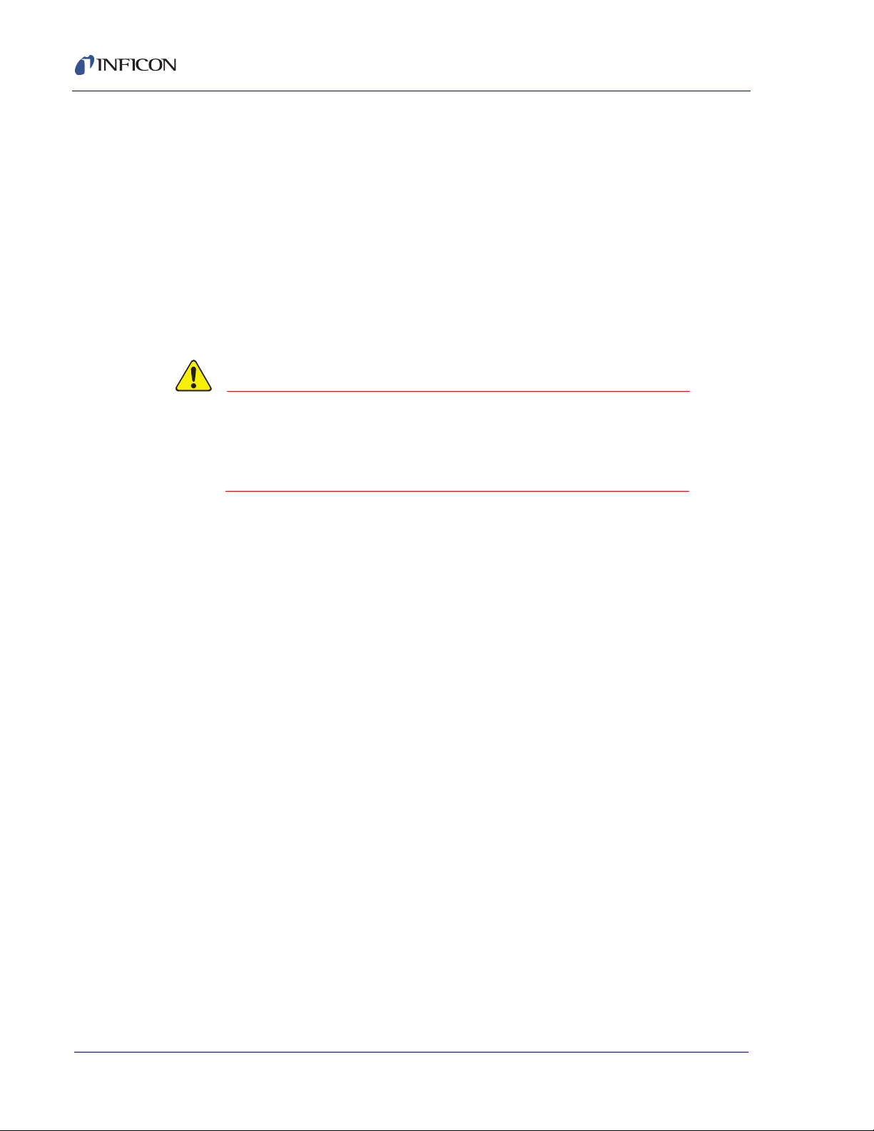
Composer Elite Operating Manual
CAUTION
The correct (user set) Reference Zero is retained until a new Reference Zero is
established, the Setpoint Temperature is changed or new carrier gas
parameters are entered.
NOTE: STEADY and AT TEMP must be visible when completing the Calibration
process. This indicates the measurement conditions are stable and a
relative equilibrium has been reached. It sometimes takes many minutes
for the light (low molecular weight) carrier gas to clean the Resonant
Chamber of any residual Precursor or other heavy gases. Remember that
some gases may also absorb on the Resonant Chamber’s walls and are
slowly released, further extending the time to reach pure carrier gas as
indicated by stable frequency.
Setting Zero Reference before the Resonant Chamber is
completely purged of precursor gas will result in an
offset and scaling error in the measured concentration.
See section 4.1.10 on page 4-8.
4.1.3 How is Performance Affected if I Use the Factory (Reference) Zero Value?
While it is most accurate to reset Reference Zero daily, excellent results can be
obtained for many processes by using the Factory Zero value for Reference Zero.
While the exact loss of reproducibility is hard to predict, it is reasonable that it will
be about two to four times worse than the specified value when monitored over
extended periods of time. This may be acceptable, and convenient, for the process.
Alternating between the Factory Zero and carefully setting the Reference Zero
occasionally will not be productive. It would be better to extend the interval between
reestablishing the Reference Zero than to alternate. An example of long term
stability is shown in section 4.1.9 on page 4-7.
PN 074-566-P1B
4 - 2
Page 59

Composer Elite Operating Manual
Frequency (Hz)
Concentration (mole %)
5
4
3
0
2
1
2000 2500 3000 35001500 4000
TMLn in H2: Impact of Error in Gamma
True
Gamma
20%
Overestimated
Gamma
10%
Underestimated
Gamma
4.1.4 What To Do when the Specific Heat Ratio for a Gas is Unknown
Quantitative accuracy for an acoustic measurement technique partially depends on
accurate knowledge of the Specific Heat Ratio,
While this ratio is known for many pure common gases, little information is
available on many of the complex Precursor molecules. The information currently
available is given in Table B-1 on page B-1. Even without exact knowledge of the
Specific Heat Ratio, useful information and reliable operation can still be obtained.
The Specific Heat Ratio of gases is a parameter that does not have a large range,
it is confined to a range of about 1.1 to 1.7 for almost every known gas.
Consequently, using the wrong Specific Heat Ratio will not make a significant error
in most cases. It is also possible to make intelligent guesses about unknown gases
using the value of the Specific Heat Ratio for a similar gas. It is almost always more
accurate to overestimate the Specific Heat Ratio than to underestimate by the
same amount; see Appendix B and Figure 4-1. Consider also that in production,
accuracy is not as important as the reproducibility. As long as the Specific Heat
Ratio is not changed, Composer Elite will produce similar results, day after day.
NOTE: Long term use of Composer Elite with some of the materials listed in
Appendix B may not be possible.
, of the individual gas species.
PN 074-566-P1B
Figure 4-1 When the specific heat ratio for a gas is unknown it is generally
better to overestimate the specific heat ratio
4 - 3
Page 60

Composer Elite Operating Manual
3940
3900
3860
3820
3780
0.16
0.12
0.08
0.04
0.00
0 200 400 600 800 1000 1200
Frequency (Hz)
Absolute Pressure (Torr)
Equivalent TMIn in H2 (mole-%)
H2- 200 sccm, 35°C
Frequency
Concentration
4.1.5 What is the Ideal Operating Environment?
In an ideal operating environment, parameters that influence the concentration
measurement do not change. Most Reactors can be configured so that the
pressure and flow through the Acoustic Sensor are held constant by independent
controllers. The precursor’s fluence into the Reactor can be maintained or changed
without altering the total flow and pressure through the Acoustic Sensor. This is
considered good practice for Reactor design.
Leave the Composer Elite System on at all times— always ready to immediately
function with best accuracy. We have not seen deterioration through continuous
use. Since all Reactors are in environmentally controlled rooms, the small
influences due to ambient temperature changes are of no concern.
4.1.6 What is the Effect of Pressure Variation?
Because not all mixtures are purely ideal and the use of diaphragms to separate
the toxic and corrosive gases from the Exciting and Receiving microphones is
required, Composer Elite displays a small influence from pressure changes. The
effects of pressure variation on concentration are shown in Figure 4-2.
Figure 4-2 Effect of pressure on apparent concentration
PN 074-566-P1B
4 - 4
Page 61

Composer Elite Operating Manual
3935
3925
3915
3905
3895
100 200 300 400 500 600 700
Flow (SCCM)
Frequency (Hz)
H2- 300 Torr
H2- 600 Torr
H2- 150 Torr
4.1.7 What is the Effect of Flow Variation?
There is virtually no flow induced effect on concentration measurement in the
Composer Elite System except at the highest flow rates, see Figure 4-3, the
pressure drop across the Acoustic Sensor is about 12 Torr [1.60 kPa] at 2000 sccm
for the Standard sensor or 6 Torr [0.80 kPa] for the High Flow sensor.
HINT: Large variations in flow rate will cause a shift in the zero concentration
point. To minimize zero shift due to flow rate change, carefully set the inlet
tubing heater temperature (Temperature Setpoint 2). The default value for
Temperature Setpoint 2 is 3 degrees higher than Temperature Setpoint 1.
Adjusting the Temperature Setpoint 2 value slightly might be necessary
depending on your process requirements.
Figure 4-3 Effect of flow on apparent concentration
PN 074-566-P1B
4.1.8 How Does This Instrumental Method Differ from Measuring the Speed of Sound by Time of Flight?
The use of a low frequency Resonant Chamber has significant advantages over
Time of Flight (TOF) methods. It allows the constructive build up of energy within
the Resonant Chamber. Plus, sound transmission in hydrogen at low frequency is
more efficient than at high frequency. This enhances the instrument’s ability to
measure concentration in hydrogen mixtures at lower pressures. Finally, the
careful intelligent manipulation of the applied frequency around the resonant
amplitude peak allows even greater precision in the determination of the speed of
4 - 5
Page 62

Composer Elite Operating Manual
0.2 m
1284 m/s
---------------------- 1.56 E-4 s transit time=
Where is the pulse?
Wavelength of 15 KHz ultrasonic in H2 (1284 m/sec x 1/15 KHz) = 0.0856 m
0.2 m
?
?
?
?
Ultrasonic
Sender
Ultrasonic
Receiver
sound. The resonant method does not lose accuracy because of uncertainty of
guessing when the center of a low energy acoustic pulse packet precisely leaves
the Sender and reaches the Receiver. See Figure 4-4.
For a TOF instrument to achieve resolution equivalent to Composer Elite
(1 part in 50,000), it must achieve time measurement precision of 3 nanoseconds.
This resolution is achievable for sophisticated instruments measuring photons or
particles, but is approximately forty times better than the resolution possible on the
poorly defined 15 kHz ultrasonic wave pulse in hydrogen. One wavelength of a
15 kHz tone is 0.0856 m, almost one half the length of a 0.2 m path length
instrument.
4.1.8.1 Calculation Example
The time interval for an acoustic pulse to travel 0.2 meters in hydrogen is computed
as follows (see equation [1] and Figure 4-4)
NOTE: The speed of sound in hydrogen is 1284 meters/second.
[1]
In order to achieve equivalent resolution to the Composer Elite resonant technique,
the TOF instrument’s ability to measure the pulse must be 1/50,000 of the transit
time, or: 1.56 E-4 (1/50,000) = 3.12 E-9 seconds
Figure 4-4 Where does the pulse begin or end?
PN 074-566-P1B
4 - 6
Page 63

4.1.9 What is the Long Term Stability of this Measurement System?
There does not appear to be any trend that might lead to any unexpected wear or
degradation with time. This data is not corrected for zero offsets due to atmospheric
pressure variations over the test period.
Using R134a in nitrogen as a test (R134a is similar in molecular weight to some
common metal organic precursor gases), the chart shown in Figure 4-5 shows
stability of +/- 5 ppm over 112 hours, even as the ambient temperature
varies by 3°C. This is equivalent to <1 ppm trimethylIndium in hydrogen.
Figure 4-5 Long term reproducibility and stability at low pressure
Composer Elite Operating Manual
PN 074-566-P1B
4 - 7
Page 64

Composer Elite Operating Manual
TMIn in H2: Impact Of Wrong Zero Frequency
-0.005
-0.025
-0.015
-0.035
0.0 2.01.51.00.5
True Concentration (mole-%)
Error (mole-%)
Zeroed at 10 Hz below
true carrier frequency
Zeroed at 20 Hz below
true carrier frequency
4.1.10 What Happens if the Reference Zero is Improperly Set?
If the Reference Zero is set when the conditions are wrong, i.e., not completely
purged of precursor gas:
1 A permanent concentration offset is introduced equal to the residual precursor
concentration when the new Reference Zero is applied. This is not corrected
until a proper Reference Zero is performed.
2 The sensitivity is altered, leading to an error proportional to the concentration.
Figure 4-6 Impact of wrong zero frequency
4 - 8
NOTE: Factory Zero will be restored if one of the carrier gas parameters
(molecular weight or ) is altered or if TEMP 1 Setpoint is changed or if
Allow User Zero is changed from Yes to No.
PN 074-566-P1B
Page 65

Composer Elite Operating Manual
MFC
Composer Elite
Acoustic Sensor
Read
Out
Back
Pressure
Controller
Pump
May require restriction to induce
flow through sample tube.
Optional:
For maximum
sensitivity or if
severe instability
exists.
Composer Elite
Sensor
Control
Unit
4.1.11 How to Sample Flow with a Composer Elite
When the flow through a process pipe exceeds the Acoustic Sensor’s 2000 sccm
limit, sampling of the process is required. In our experience, bypassing some of the
process gas through the Acoustic Sensor can compromise Composer Elite
precision, long term accuracy and add noise due to pressure and flow fluctuations.
Our recommendation is to “buffer” the flow through the Acoustic Sensor by adding
a Mass Flow Controller (MFC) upstream of the Acoustic Sensor in the sample
tubing. This device will stabilize the flow and in most cases restore Composer Elite
full measurement capability. In some extreme cases it may be necessary to also
add downstream buffering with a Back Pressure Controller. Try to maintain at least
200 Torr [26.66 kPa] in the Acoustic Sensor for best operation. It may be necessary
to slightly restrict the process tubing in order to induce flow through the sample
tube. See Figure 4-7.
An added benefit of adding the MFC to the sample tube is that flow through the
Acoustic Sensor is made visible and easily verified.
Figure 4-7 Flow sampling
PN 074-566-P1B
4 - 9
Page 66

Composer Elite Operating Manual
This page is intentionally blank.
4 - 10
PN 074-566-P1B
Page 67

Composer Elite Operating Manual
Chapter 5
Remote Communications
5.1 Introduction
Composer Elite supports RS-232C and DeviceNet communications, and may be
remotely controlled, programmed or interrogated. This is accomplished through
remote communications and the use of a remote command set. Composer Elite will
respond to messages that contain these commands. It will accept and operate one
message at a time. It will respond to each command by carrying out valid
operations and/or returning a message to the sender. A host/server relationship is
established in remote communications. Composer Elite, as server, responds to the
remote host’s commands.
5.2 General Type Definitions for Remote Communications
General Type Definitions
<Float> = 4 byte, single precision ANSII standard floating point, low to high
<String> = Variable length, null terminated ASCII characters
<Byte> = 1 Byte
<Encode> = 4 Byte, low to high
<Short> = 2 Bytes, low to high
<Integer> = 4 Bytes, low to high
NOTE: All data elements larger than a byte are in little-endian form, both those
sent and returned.
PN 074-566-P1B
5.3 RS-232 Communications
For RS-232 communications, an industry standard 9-pin D-sub-miniature
connector is required to connect to Composer Elite. See Figure 5-1 and Table 5-1.
Both the host and server must have the same form of communications equipment
and complementary set up. For serial communications, baud rates must match and
so must the data word format. Hardware handshaking is not supported.
The word format for bit serial lines (RS-232C) is comprised of ten signal bits:
eight data bits, one start bit, one stop bit and no parity.
The eight data bits comprise a byte of information or character whose ASCII value
ranges from 0 to 255.
The length of the cable is limited to 15.2 m (50 ft.).
5 - 1
Page 68

Composer Elite Operating Manual
CAUTION
1
9
Only serial communications baud rate of 115,200 is supported.
The communications interface operates using the DCE (Data Communications
Equipment) configuration.
NOTE: Some RS-232 hardware/software combinations may occasionally
cause a command to not be recognized by Composer Elite.
Consequently, all communications should include an automatic retry
procedure if a response is not received within three seconds.
RS-232 uses single-ended signaling with all signals sharing
a common ground, making it susceptible to cross-talk and
noise if the RS-232 cable is not properly shielded and not
routed away from sources of noise. A very high data rate can
overwhelm the internal buffers of the computer, resulting in
data loss. Computer configuration (such as a power setting
that allows the computer to sleep during a run) can cause
data loss. Data loss can occur due to issues inherent to the
Windows operating system, including the diversion of
computer resources when Windows Automatic Update or
antivirus software checks for updates on the Internet.
Figure 5-1 9-pin type “D” female connector
Table 5-1 RS-232C 9-pin type "D" connector pin connections
Pin# Description DB9* DB25**
1 Not Used 1 -
2 TXD Data transmitted by the Sensor Control Unit 2 3
3 RXD Data received by the Sensor Control Unit 3 2
4 DSR Not Used 4 -
5 GND Signal Ground 5 7
6 DTR Not Used 6 6
7 CTS Not Used 7 4
8 RTS Not Used 8 -
9 GND Not Used 9 -
*Host
**IBM compatible computer connector
PN 074-566-P1B
5 - 2
Page 69

5.4 DeviceNet Communications
CAUTION
For DeviceNet Messaging, the transmit/receive message count field is used by the
process transmitting the message to indicate that data is available to read and
process.
The application will populate the Composer Elite command field with the data to be
transmitted to Composer Elite and increment the Transmit Message Count field.
This will indicate to Composer Elite that there is a command ready to be
processed.
Composer Elite constantly monitors the value in the Transmit Message Count
field. When Composer Elite detects a change in the value of the count field, it will
process the command and put the response in the Composer Elite Response field
and increment the Receive Message Count value.
The application will periodically read the Receive Message Count field for a
change in the count. When a count is detected, this indicates to the application that
Composer Elite has completed processing the command sent and a response is in
the Composer Elite Response field.
Upon initialization, the application must read the Receive Message Count field
and use it as its initial receive/transmit count values. The transmit message count
must be given ahead of the desired command message. Responses, on
DeviceNet, will also be preceded by a receive byte count.
Composer Elite Operating Manual
NOTE: DeviceNet communications used with Composer Elite Multi-Sensor
Software must be used with a Beckhoff FC5201 DeviceNet computer
Interface card.
The DeviceNet cable requires 24 volts. This voltage is not supplied by the
Sensor Control Unit. If the Beckhoff FC5201 DeviceNet computer interface
card does not detect 24 volts, it will not work and flag an error.
If remote communications are used, any DeviceNet device will be suitable
for DeviceNet communications.
PN 074-566-P1B
DeviceNet communications over a single bus can allow data
to be inadvertently sent and received simultaneously,
resulting in the loss of that particular data set (this is not an
issue when using the Composer Elite’s full-duplex RS-232).
A very high data rate can overwhelm the internal buffers of
the computer, resulting in data loss. Computer configuration
(such as a power setting that allows the computer to sleep
during a run) can cause data loss. Data loss can occur due
to issues inherent to the Windows operating system,
including the diversion of computer resources when
Windows Automatic Update or antivirus software checks for
updates on the Internet.
5 - 3
Page 70

Composer Elite Operating Manual
5.4.1 DeviceNet Objects
5.4.1.1 CIP Type Definitions
Refer to ODVA™ CIP™ classes.
5.4.1.2 Identity Objects (01h)
Table 5-2 shows the Identity objects. The supported services are:
Class - Get Attribute Single (Revision, UINT, 0001h)
Instance - Get Attribute Single, Reset
Table 5-2 Instance #1 Attributes (Identity Object)
# Name Access Type Comments
1 Vendor ID Get UINT 0279h
2 Device Type Get UINT 000Ch (Communications Adapter)
3 Product Code Get UINT 003Dh
4 Revision Get Struct. of
{USINT,
USINT}
5 Status Get WORD Bit 0 = Module Owned
6 Serial Number Get UDINT Unique Number
7 Product Name Get Short
String
Major, Minor Controller Firmware Version
Bit 1 = (reserved)
Bit 2 = Configured
Bit 3 = (reserved)
Bits 4-7 = Extended Device Status
0000b = unknown
0001b = Faulted I/O Connection
0010b = No I/O Connection est.
0011B = Non-volatile config. Bad
0110b = Connection in Run mode
0111b = Connections in Idle mode
Bit 8 = Set for minor recoverable faults
Bit 9 = Set for minor unrecoverable faults
Bit 10 = Set for major recoverable faults
Bit 11 = Set for major recoverable faults
Bits 12-15 = reserved
"Composer Elite"
PN 074-566-P1B
5 - 4
Page 71

Composer Elite Operating Manual
5.4.1.3 Message Router (02h)
Not used.
5.4.1.4 DeviceNet Object (03h)
DeviceNet objects are shown in Table 5-3. The supported services are:
Class - Get Attribute Single (Revision, UINT, 0002h)
Instance - Get/Set Attribute Single, Allocate Master/ Slave Connection Set
(4Bh), Release Group 2 Identifier Set (4Ch)
Table 5-3 Instance #1 Attributes (DeviceNet Object)
# Name Access Type Comments
1 MAC ID Get/Set(a) UINT Currently used MAC ID
2 Baud Rate Get/Set(a) UINT Currently used Baud Rate
0 = 125 kbps
1 = 250 kbps
2 = 500 kbps
3 BOI Get/Set UINT False
4 Bus Off Counter Get USINT 00h
5 Allocation Information Get Stru ct.
BYTE,
USINT
10 Quick Connect Get/Set BOOL (True) Disable Quick Connect (default)
100 Disable Auto Baud (b) Set BOOL (True) Disable Auto Baud (default)
(a) Attribute may not be able to be set if configuration does not allow it.
(b) This setting is stored in non-volatile memory.
PN 074-566-P1B
(BYTE) Allocation of choice byte
of:
(USINT) MAC ID of master
(False) Enable Quick Connect
(False) Enable Auto Baud
5 - 5
Page 72

Composer Elite Operating Manual
5.4.1.5 Assembly Object (04h)
This assembly object uses static assemblies and holds the Composer Elite I/O.
The assembly instance IDs used are in the vendor specific range. Specifics on the
CE Out(Command) and CE IN(Response) are detailed later in the section 5.5.1,
Command, on page 5-22 and section 5.5.2, Response, on page 5-22.
NOTE: This is the object used to interact with Composer Elite Command &
Response messaging. This object can alternatively be used to publish data
as selected by the I/O Data Format attribute in the I/O Data Format Object.
The supported services are:
Class - None
Instance - Get/Set Attribute Single
Table 5-4 Instance 64h Attribute (Producing Instance)
# Name Access Type Comments
3 CE Message Get Array of
byte
Data Corresponds to Composer Elite Input
(CE IN)
Table 5-5 Instance 96h Attribute (Consuming Instance)
# Name Access Type Comments
3 CE Message Set Array of
byte
Data Corresponds to Composer Elite
output (CE OUT)
PN 074-566-P1B
5 - 6
Page 73

Composer Elite Operating Manual
5.4.1.6 Connection Object (05h)
Connection objects are shown in Table 5-6.
The supported services are:
Class - Get Attribute Single (Revision, UINT, 0001h)
Instance - Get/Set Attribute Single
Table 5-6 Instance #1,#10...#14 (Explicit Messaging)
# Name Access Type Comments
1 State Get USINT 0 = Nonexistent
1 = Configuring
2 = Waiting for Connections ID
3 = Established
4 = Timeout
5 = Deferred Delete
2 Instance Type Get USINT 0000h (explicit messaging type)
3 Transport Class Trigger Get BYTE 83h (Server, Transport class 3)
4 Produced Connection ID Get UINT -
5 Consumed Connection ID Get UINT -
6 Initial Comm Characteristics Get BYTE 21 = Instance#1
33 = Instance #10..#14
7 Produced Connection Size Get UINT 262
8 Consumed Connection Size Get UINT 262
9 Expected Packet Rate Get/Set(a) UINT 2500ms
12 Watchdog Timeout Action Get/Set(a) USINT 0001h = Auto Delete (default)
0003h = Deferred delete
13 Produced Connection Path Length Get UINT 0000h (No connection path)
14 Produced Connection Path Get EPATH -
15 Consumed Connection Path
Length
16 Consumed Connection Path Get EPATH -
PN 074-566-P1B
17 Production Inhibit Time Get UINT 0000h
(a) Not able to be set on UCMM explicit message connections (Instance 10...14)
Get UINT 0000h (no connection path)
5 - 7
Page 74

Composer Elite Operating Manual
Table 5-7 Instance #2 (Poll or "COS/Cyclic Consuming")
# Name Access Type Comments
1 State Get USINT 0 = Nonexistent
1 = Configuring
2 = Waiting for Connections ID
3 = Established
4 = Timeout
2 Instance Type Get USINT 0000h (I/O Connection)
3 Transport Class Trigger Get BYTE 82h = Server, Polled, Class 2
80h = Server, COS/Cyclic, Class 0,
No Ack.
82h = Server, COS/Cyclic, Class 2, Ack.
4 Produced Connection ID Get UINT FFFFh = Not Consuming (COS/Cyclic)
Other = CAN ID for transmission
5 Consumed Connection ID Get UINT -
6 Initial Comm Characteristics Get BYTE 01h = Polled
- Produces over message, group 1
- Consumes over message, group 2
F1h = COS/Cyclic, No Ack.
- Consumes over message, group 2
01h = COS.Cyclic, Ack.
-Produces over message, group 1
- Consumes over message, group2
7 Produced Connection Size Get UINT 0000h = COS/Cyclic
other = Size of Fieldbus Input data (polled)
8 Consumed Connection Size Get UINT Size of Fieldbus Output data
9 Expected Packet Rate Get/Set(a) UINT -
12 Watchdog Timeout Action Get/Set(a) USINT 0000h (Transition to the timed out state)
13 Produced Connection Path Length Get UINT 0000h (COS/Cyclic)
0007h (Polled)
14 Produced Connection Path Get EPATH No Value (COS/Cyclic)
20 04 25 64 00 30 03h (polled)
15 Consumed Connection Path
Length
16 Consumed Connection Path Get EPATH 20 04 25 96 00 30 03h
17 Production Inhibit Time Get UINT 0000h
Get UINT 0007h
PN 074-566-P1B
5 - 8
Page 75

Composer Elite Operating Manual
Table 5-8 Instance #3 (Bit-Strobe)
# Name Access Type Comments
1 State Get USINT 0 = Nonexistent
1 = Configuring
2 = Waiting for Connections ID
3 = Established
4 = Timeout
2 Instance Type Get USINT 0001h (I/O Connection)
3 Transport Class Trigger Get BYTE 82h (Transport class and Trigger Server,
Cyclic, Class 2)
4 Produced Connection ID Get UINT -
5 Consumed Connection ID Get UINT -
6 Initial Comm Characteristics Get BYTE Produces over message, group 1
Consumes over message, group 2
7 Produced Connection Size Get UINT 0...8 bytes depending in Fieldbus Input
size
8 Consumed Connection Size Get UINT 0008h
9 Expected Packet Rate Get/Set(a) UINT -
12 Watchdog Timeout Action Get/Set(a) USINT 0000h (Transition to the timed out state)
13 Produced Connection Path Length Get UINT 0007h
14 Produced Connection Path Get EPATH 20 04 25 64 00 30 03h
15 Consumed Connection Path
Length
16 Consumed Connection Path Get EPATH 20 04 25 96 00 30 03h
17 Production Inhibit Time Get UINT 0000h
PN 074-566-P1B
Get UINT 0007h
5 - 9
Page 76

Composer Elite Operating Manual
Table 5-9 Instance #4 (COS/Cyclic Producing)
# Name Access Type Comments
1 State Get USINT 0 = Nonexistent
1 = Configuring
2 = Waiting for Connections ID
3 = Established
4 = Timeout
2 Instance Type Get USINT 0001h (I/O Connection)
3 Transport Class Trigger Get BYTE 00h = Client, Cyclic, Class 0, No Ack.
10h = Client, COS, Class 0, No Ack.
02h = Client, Cyclic, Class 2, Ack.
12h = Client, COS, Class 2, Ack.
4 Produced Connection ID Get UINT CAN ID for Transmission
5 Consumed Connection ID Get UINT FFFFh = No Ack.
Other = CAN ID for reception (Ack.)
6 Initial Comm Characteristics Get BYTE 0Fh = Producing only over message,
group 1 (No Ack.)
01h = Produces over message, group 1
- Consumes over message, group 2 (Ack.)
7 Produced Connection Size Get UINT Corresponds to Fieldbus Input size
8 Consumed Connection Size Get UINT 0000h (consumes 0 bytes on this
connection)
9 Expected Packet Rate Get/Set(a) UINT Timing associated with this connection
12 Watchdog Timeout Action Get/Set(a) USINT 0000h (Transition to the timed out state)
13 Produced Connection Path Length Get UINT 0007h
14 Produced Connection Path Get EPATH 20 04 25 96 00 30 03h
15 Consumed Connection Path
Length
16 Consumed Connection Path Get EPATH No Value (No Ack.)
17 Production Inhibit Time Get UINT 0000h
Get UINT 0000h (No Ack.)
0005h (Ack.)
20 2B 25 01 00h (Ack.)
PN 074-566-P1B
5 - 10
Page 77

5.4.1.7 Acknowledge Handler Object (2Bh)
The supported services are:
Class - Get Attribute Single (Revision, UINT, 0001h)
Instance - Get/Set Attribute Single
Table 5-10 Instance Attribute (01h)
# Name Access Type Comments
1 Acknowledge Timer Get/Set UINT 16ms
2 Retry Limits Get/Set USINT 01h
3 Producing Connection
Instance
5.4.1.8 I/O Data Format Object (64h)
The I/O Data Format Object is a vendor specific object used to determine how the
contents of the Assembly Object buffers are formatted and used. The Composer
Elite Output (CE OUT) and the Composer Elite Input (CE IN) can be used to
exchange INFICON messages. Alternatively, the Composer Elite Output (CE OUT)
can be used to cache a predefined set of data values.
Composer Elite Operating Manual
Get UINT 04h
Per the Composer Elite Cache Data Sets (see section 5.4.2, DeviceNet Data Sets,
on page 5-12), all INFICON data sets are formatted per these byte tables and
accessed via the Assembly Object (04h, Instance 96h). The Composer Elite will
continuously update these data values as the values change. A change indicator
in the form of a count field will be maintained to indicate when the values may have
changed. Also, an update in progress indicator is given to indicate when a data set
could be partially updated. The data set currently published is reported to help the
host correctly interpret the data present.
NOTE: The data set functionality is only available when a Polled, COS, Cyclic or
Bit Strobe connection is detected.
PN 074-566-P1B
The supported services are:
Class - None
Instance - Get/Set Attribute Single
5 - 11
Page 78

Composer Elite Operating Manual
Table 5-11 Instance Attributes (01h)
# Name Access Type Comments
100 I/O Data Format Get/Set UINT 0 = INFICON Messaging
5.4.2 DeviceNet Data Sets
5.4.2.1 Initialization
1 = Sensor 1 Data Set
2 = Sensor 2 Data Set
3 = Sensor 3 Data Set
4 = Sensor 4 Data Set
5 = Sensor 5 Data Set
6 = All 5 Sensor Card Data
Set
7 = Sensors 1,2,3 Err/Wrn
Data Set
8 = Sensors 4,5 Err/Wrn
Data Set
9 = All 5 Sensor Card
Concentration
After a power cycle, Composer Elite will default to expecting and responding to
INFICON messages. To instruct Composer Elite to cache data in CE OUT instead,
in the host computer set the I/O Data Set attribute to a non-zero value. The value
will specify to Composer Elite which data set to cache. This value can be changed.
When Composer Elite is caching data to CE OUT, CE IN is not used.
NOTE: Switching data sets, or between INFICON messages and a data set, may
5.4.2.2 Data
5.4.2.2.1 Data Sets
Data sets are preceded by a Count, an Update In Progress flag and a Cached Data
Set value. The Cached Data Set value has been repeated in the following byte
descriptions for improved clarity.
Table 5-12 Cached data sets values byte descriptions
Update in
Progress Flag
Cache Data
Composer
Elite Data
Valu es
take a few moments to complete.
Value Size (bits) Field
Type
Count ----------- 16 Short Value that when monitored indicates when
0-1 8 Byte TRUE if the data values are being updated.
1-9 9 Byte Indicates how to interpret the following bytes
Set
----------- (N-3) * 8
bits
Byte Data values. See Data Set tables.
Definition
data values may have changed.
FALSE otherwise. Used to determine if a
partial value could be present.
of data.
PN 074-566-P1B
5 - 12
Page 79

Composer Elite Operating Manual
5.4.2.2.2 Sensor 1-5 Data Set
All of the basic and advanced data associated with a single sensor. The data set
can be requested for any of the 5 possible sensors.
Table 5-13 Sensor 1-5 data set
Name Range Data Type Note
Cached Data Set 1-5 Byte Byte
Boards Present
Indicator
SS, LS, MH1/PC,
MH2/UZ, AT, CS,
ER, RS, BM, WA
Measurement
Mode
Concentration 0.0 – 100.0
Temperature 1 30.0 – 65.0 C Float The current temperature value of first
Temperature 2 30.0 – 65.0 C Float The current temperature value of second
Errors ------ Integer Current error value. Refer to Table 5-22 for a
Warnings ------ Integer Current warning value See Table 5-23 for a
Heater 1 Status 0 - 6 Short 0 = Off
Heater 2 Status 0 - 6 Short 0 = Off
PN 074-566-P1B
Sample Number 0 – 255 Byte The current sample number
Frequency Float
Amplitude Float
Heater 1 Current
Drawn
Heater 2 Current
Drawn
R Squared Float
0 – 0x1F Byte Byte
Refer to
Table 5-18
IDLE = 0
READY =1
SEARCH = 2
TRACK = 3
QTRACK = 4
BASELINE = 6
mole %
Integer Status bits Refer to Table 5-18.
Encoded Current System Measurement Mode.
Float The current concentration value.
Float
Float
SS bit is not relevant in the data set format.
temperature sensor.
temperature sensor.
complete description of the errors.
complete description of the warnings.
1 = Not at temp
2 = At temp
3 = Failed
4 = Cable Disconnected
5 = Near Temp
6 = Over Temp
1 = Not at temp
2 = At temp
3 = Failed
4 = Cable Disconnected
5 = Near Temp
6 = Over Temp
5 - 13
Page 80

Composer Elite Operating Manual
Table 5-13 Sensor 1-5 data set (continued)
Name Range Data Type Note
Standard Error Float
Q Float
PWM 1 Integer
PWM 2 Integer
Acoustic Gain Byte
D Gain Heater 1 Float
I Gain Heater 1 Float
P Gain Heater 1 Float
D Gain Heater 2 Float
I Gain Heater 2 Float
P Gain Heater 2 Float
RAV Float NOTE: RAV value is calculated during the
Controller Card
Board Temperature
Sensor Card Board
Temperature
Track and Q Track measurement modes. The
RAV value will remain steady at the last RAV
value calculated during the other
measurement modes.
Float
Float
5.4.2.2.3 All 5 Sensor Card Data Set
This data set returns a compound set of current data values for all five of the sensor
cards.
Table 5-14 All sensor card data set
Name Range Data Type Note
Cached Data Set 6 Byte Numeric value of the data set cached.
Boards Present
Indicator
Sensor 1
SS, LS, MH1/PC,
MH2/UZ, AT, CS,
ER, RS, BM, WA
Sensor 1
Measurement
Mode
Sensor 1
Concentration
Sensor 1
Temperature 1
0 – 0x1F Byte Bitwise: Bits 0 – 4 set indicate sensor board 1
Refer to
Table 5-18
IDLE = 0
READY =1
SEARCH = 2
TRACK = 3
QTRACK = 4
BASELINE = 6
0.0 – 100.0
mole %
30.0 – 65.0 C Float The current temperature value of first
– 5 present, respectively.
Integer Status bits Refer to Table 5-18.
SS bit is not relevant in the data set format.
Encoded Current System Measurement Mode.
Float The current concentration value.
temperature sensor.
PN 074-566-P1B
5 - 14
Page 81

Composer Elite Operating Manual
Table 5-14 All sensor card data set (continued)
Name Range Data Type Note
Sensor 1
Temperature 2
Sensor 1
Heater 1 Status
Sensor 1
Heater 2 Status
Sensor 1
Sample Number
Sensor 2
SS, LS, MH1/PC,
MH2/UZ, AT, CS,
ER, RS, BM, WA
Sensor 2
Measurement
Mode
Sensor 2
Concentration
Sensor 2
Temperature 1
Sensor 2
Temperature 2
Sensor 2
PN 074-566-P1B
Heater 1 Status
Sensor 2
Heater 2 Status
Sensor 2
Sample Number
30.0 – 65.0 C Float The current temperature value of second
temperature sensor.
0 - 6 Short 0 = Off
1 = Not at temp
2 = At temp
3 = Failed
4 = Cable Disconnected
5 = Near Temp
6 = Over Temp
0 - 6 Short 0 = Off
1 = Not at temp
2 = At temp
3 = Failed
4 = Cable Disconnected
5 = Near Temp
6 = Over Temp
0 – 255 Byte The current sample number.
Refer to
Table 5-18
IDLE = 0
READY =1
SEARCH = 2
TRACK = 3
QTRACK = 4
BASELINE = 6
0.0 – 100.0
mole %
30.0 – 65.0 C Float The current temperature value of first
30.0 – 65.0 C Float The current temperature value of second
0 - 6 Short 0 = Off
0 - 6 Short 0 = Off
0 – 255 Byte The current sample number.
Integer Status bits Refer to Table 5-18.
SS bit is not relevant in the data set format.
Encoded Current System Measurement Mode.
Float The current concentration value.
temperature sensor.
temperature sensor.
1 = Not at temp
2 = At temp
3 = Failed
4 = Cable Disconnected
5 = Near Temp
6 = Over Temp
1 = Not at temp
2 = At temp
3 = Failed
4 = Cable Disconnected
5 = Near Temp
6 = Over Temp
5 - 15
Page 82

Composer Elite Operating Manual
Table 5-14 All sensor card data set (continued)
Name Range Data Type Note
Sensor 3
SS, LS, MH1/PC,
MH2/UZ, AT, CS,
ER, RS, BM, WA
Sensor 3
Measurement
Mode
Sensor 3
Concentration
Sensor 3
Temperature 1
Sensor 3
Temperature 2
Sensor 3
Heater 1 Status
Sensor 3
Heater 2 Status
Sensor 3
Sample Number
Sensor 4
SS, LS, MH1/PC,
MH2/UZ, AT, CS,
ER, RS, BM, WA
Sensor 4
Measurement
Mode
Sensor 4
Concentration
Sensor 4
Temperature 1
Sensor 4
Temperature 2
Refer to
Table 5-18
IDLE = 0
READY =1
SEARCH = 2
TRACK = 3
QTRACK = 4
BASELINE = 6
0.0 – 100.0
mole %
30.0 – 65.0 C Float The current temperature value of first
30.0 – 65.0 C Float The current temperature value of second
0 - 6 Short 0 = Off
0 - 6 Short 0 = Off
0 – 255 Byte The current sample number.
Refer to
Table 5-18
IDLE = 0
READY =1
SEARCH = 2
TRACK = 3
QTRACK = 4
BASELINE = 6
0.0 – 100.0
mole %
30.0 – 65.0 C Float The current temperature value of first
30.0 – 65.0 C Float The current temperature value of second
Integer Status bits Refer to Table 5-18.
Encoded Current System Measurement Mode.
Float The current concentration value.
Integer Status bits Refer to Table 5-18.
Encoded Current System Measurement Mode.
Float The current concentration value.
SS bit is not relevant in the data set format.
temperature sensor.
temperature sensor.
1 = Not at temp
2 = At temp
3 = Failed
4 = Cable Disconnected
5 = Near Temp
6 = Over Temp
1 = Not at temp
2 = At temp
3 = Failed
4 = Cable Disconnected
5 = Near Temp
6 = Over Temp
SS bit is not relevant in the data set format.
PN 074-566-P1B
temperature sensor.
temperature sensor.
5 - 16
Page 83

Composer Elite Operating Manual
Table 5-14 All sensor card data set (continued)
Name Range Data Type Note
Sensor 4
Heater 1 Status
Sensor 4
Heater 2 Status
Sensor 4
Sample Number
Sensor 5
SS, LS, MH1/PC,
MH2/UZ, AT, CS,
ER, RS, BM, WA
Sensor 5
Measurement
Mode
Sensor 5
Concentration
Sensor 5
Temperature 1
Sensor 5
Temperature 2
Sensor 5
Heater 1 Status
PN 074-566-P1B
Sensor 5
Heater 2 Status
Sensor 5
Sample Number
0 - 6 Short 0 = Off
1 = Not at temp
2 = At temp
3 = Failed
4 = Cable Disconnected
5 = Near Temp
6 = Over Temp
0 - 6 Short 0 = Off
1 = Not at temp
2 = At temp
3 = Failed
4 = Cable Disconnected
5 = Near Temp
6 = Over Temp
0 – 255 Byte The current sample number.
Refer to
Table 5-18
IDLE = 0,
READY =1
SEARCH = 2
TRACK = 3
QTRACK = 4
BASELINE = 6
0.0 – 100.0
mole %
30.0 – 65.0 C Float The current temperature value of first
30.0 – 65.0 C Float The current temperature value of second
0 - 6 Short 0 = Off
0 - 6 Short 0 = Off
0 – 255 Byte The current sample number.
Integer Status bits Refer to Table 5-18.
SS bit is not relevant in the data set format.
Encoded Current System Measurement Mode.
Float The current concentration value.
temperature sensor.
temperature sensor.
1 = Not at temp
2 = At temp
3 = Failed
4 = Cable Disconnected
5 = Near Temp
6 = Over Temp
1 = Not at temp
2 = At temp
3 = Failed
4 = Cable Disconnected
5 = Near Temp
6 = Over Temp
5 - 17
Page 84

Composer Elite Operating Manual
5.4.2.2.4 Sensors 1,2,3 Error/Warning Data Set
This data set returns a compound set of current data values for three of the five
sensor cards.
Table 5-15 Sensors 1,2,3 error/warning data set
Name Range Data Type Note
Cached Data Set 7 Byte Numeric value of the data set cached.
Boards Present
Indicator
Sensor 1
SS, LS, MH1/PC,
MH2/UZ, AT, CS,
ER, RS, BM, WA
Sensor 1
Errors
Sensor 1
Warnings
Sensor 1
Sample Number
Sensor 1
Frequency
Sensor 1
Amplitude
Sensor 1
Heater 1 Current
Drawn
Sensor 1
Heater 2 Current
Drawn
Sensor 2
SS, LS, MH1/PC,
MH2/UZ, AT, CS,
ER, RS, BM, WA
Sensor 2
Errors
Sensor 2
Warnings
Sensor 2
Sample Number
Sensor 2
Frequency
Sensor 2
Amplitude
Sensor 2
Heater 1 Current
Drawn
Sensor 2
Heater 2 Current
Drawn
0 – 0x1F Byte Bitwise: Bits 0 – 4 set indicate sensor board
Refer to
Table 5-18
------ Integer Current error value Refer to Table 5-22 for a
------ Integer Current warning value Refer to Table 5-23 for
0 – 255 Byte The current sample number.
Refer to
Table 5-18
------ Integer Current error value. Refer to Table 5-22 for a
------ Integer Current warning value Refer to Table 5-23 for
0 – 255 Byte The current sample number.
1 – 5 present, respectively.
Integer Status bits Refer to Table 5-18
SS bit is not relevant in the data set format.
complete description of the errors.
a complete description of the warnings.
Float
Float
Float
Float
Integer Status bits Refer to Table 5-18.
SS bit is not relevant in the data set format.
complete description of the errors.
PN 074-566-P1B
a complete description of the warnings.
Float
Float
Float
Float
5 - 18
Page 85

Composer Elite Operating Manual
Table 5-15 Sensors 1,2,3 error/warning data set (continued)
Name Range Data Type Note
Sensor 3
SS, LS, MH1/PC,
MH2/UZ, AT, CS,
ER, RS, BM, WA
Sensor 3
Errors
Sensor 3
Warnings
Sensor 3
Sample Number
Sensor 3
Frequency
Sensor 3
Amplitude
Sensor 3
Heater 1 Current
Drawn
Sensor 3
Heater 2 Current
Drawn
Refer to
Table 5-18
------ Integer Current error value. Refer to Table 5-22 for a
------ Integer Current warning value. Refer to Table 5-23 for
0 – 255 Byte The current sample number.
Integer Status bits Refer to Table 5-18.
SS bit is not relevant in the data set format.
complete description of the errors.
a complete description of the warnings.
Float
Float
Float
Float
5.4.2.2.5 Sensors 4,5 Error/Warning Data Set
This data set returns a compound set of current data values for two of the five
sensor cards.
Table 5-16 Sensors 4,5 error/warning data set
Name Range Data Type Note
Cached Data Set 8 Byte Numeric value of the data set cached.
Boards Present
Indicator
Sensor 4
SS, LS, MH1/PC,
PN 074-566-P1B
MH2/UZ, AT, CS,
ER, RS, BM, WA
Sensor 4
Errors
Sensor 4
Warnings
Sensor 4
Sample Number
Sensor 4
Frequency
Sensor 4
Amplitude
0 – 0x1F Byte Bitwise: Bits 0 – 4 set indicate sensor board 1
– 5 present, respectively.
Refer to
Table 5-18
------ Integer Current error value. Refer to Table 5-22 for a
------ Integer Current warning value. Refer to Table 5-23 for
0 – 255 Byte The current sample number.
Integer Status bits Refer to Table 5-18.
SS bit is not relevant in the data set format.
complete description of the errors.
a complete description of the warnings.
Float
Float
5 - 19
Page 86

Composer Elite Operating Manual
Table 5-16 Sensors 4,5 error/warning data set
Name Range Data Type Note
Sensor 4
Heater 1 Current
Drawn
Sensor 4
Heater 2 Current
Drawn
Sensor 5
SS, LS, MH1/PC,
MH2/UZ, AT, CS,
ER, RS, BM, WA
Sensor 5
Errors
Sensor 5
Warnings
Sensor 5
Sample Number
Sensor 5
Frequency
Sensor 5
Amplitude
Sensor 5
Heater 1 Current
Drawn
Sensor 5
Heater 2 Current
Drawn
Refer to
Table 5-18
------ Integer Current error value. Refer to Table 5-22 for a
------ Integer Current warning value. Refer to Table 5-23 for
0 – 255 Byte The current sample number.
Float
Float
Integer Status bits Refer to Table 5-18.
Float
Float
Float
Float
SS bit is not relevant in the data set format.
complete description of the errors.
a complete description of the warnings.
5.4.2.2.6 5 Sensors' Concentration Data Set
This data set returns a compound set of concentration values for all five of the
sensor cards.
Table 5-17 5 sensors' concentration data set
Name Range Data Type Note
Cached Data Set 9 Byte Numeric value of the data set cached.
Boards Present
Indicator
Sensor 1
SS, LS, MH1/PC,
MH2/UZ, AT, CS,
ER, RS, BM, WA
Sensor 1
Concentration
Sensor 2
SS, LS, MH1/PC,
MH2/UZ, AT, CS,
ER, RS, BM, WA
0 – 0x1F Byte Bitwise: Bits 0 – 4 set indicate sensor board
Refer to
Table 5-18
0.0 – 100.0
mole %
Refer to
Table 5-18
PN 074-566-P1B
1 – 5 present, respectively.
Integer Status bits Refer to Table 5-18.
SS bit is not relevant in the data set format.
Float The current concentration value.
Integer Status bits Refer to Table 5-18.
SS bit is not relevant in the data set format.
5 - 20
Page 87

Composer Elite Operating Manual
Table 5-17 5 sensors' concentration data set (continued)
Name Range Data Type Note
Sensor 2
Concentration
Sensor 3
SS, LS, MH1/PC,
MH2/UZ, AT, CS,
ER, RS, BM, WA
Sensor 3
Concentration
Sensor 4
SS, LS, MH1/PC,
MH2/UZ, AT, CS,
ER, RS, BM, WA
Sensor 4
Concentration
Sensor 5
SS, LS, MH1/PC,
MH2/UZ, AT, CS,
ER, RS, BM, WA
Sensor 5
Concentration
0.0 – 100.0
mole %
Refer to
Table 5-18
0.0 – 100.0
mole %
Refer to
Table 5-18
0.0 – 100.0
mole %
Refer to
Table 5-18
0.0 – 100.0
mole %
Float The current concentration value.
Integer Status bits Refer to Table 5-18.
SS bit is not relevant in the data set format.
Float The current concentration value.
Integer Status bits Refer to Table 5-18.
SS bit is not relevant in the data set format.
Float The current concentration value.
Integer Status bits Refer to Table 5-18.
SS bit is not relevant in the data set format.
Float The current concentration value.
5.4.3 DeviceNet INFICON Messaging
All information exchanges are formatted and accessed via the Assembly Object
(04h, Instances 64h, 96h). Transactions with Composer Elite follow the form of
Host setting the Assembly Object data field (CE IN data) following the content
below (starting at section 5.4.3) and when the change indicator (Transmit / Receive
Message Count field) changes the response content is ready to be read out. Each
new command (CE IN data) must update the Transmit / Receive Message Count
field to signal the Composer Elite communications process that a new command is
pending.
NOTE: The body of the CE IN and CE OUT data block (bytes 2 … n) after the
PN 074-566-P1B
Transmit / Receive Message Count field are identical to messages
exchanged over RS-232.
5.5 Message Format
Standard message protocol serves as a structure for the contained command or
response information. It also can provide a level of acknowledgment between the
host and server and a mechanism for verifying the information content.
5 - 21
Page 88

Composer Elite Operating Manual
5.5.1 Command
This section describes the command format.
See section 5.6, Communication Commands, on page 5-27 for details on specific
command IDs.
The message received by Composer Elite contains a data packet preceded by a
length and terminated by a checksum.
Composer Elite will always send a response to any command it receives.
5.5.1.1 Command Packet (Host to Composer Elite Message)
<Length><Message><Checksum>
Length . . . . . . . . . . . . . . . . . . . . . . . 2 bytes Low / High (not including checksum
or length bytes). Numeric value representing
the number of characters in the command. In
order of transmission, the low byte will
precede the high byte. Normally, the number
for characters will be less than 9. In this case,
the low byte will contain the character count
while the high byte will have zero value.
Message . . . . . . . . . . . . . . . . . . . . . <Command>
Checksum . . . . . . . . . . . . . . . . . . . . 1 byte, sum, modulo 256, of all bytes, not
5.5.2 Response
This section describes the response format that is returned in the data field of the
response message. See section 5.6, Communication Commands, on page 5-27 for
more details on responses. The message sent by Composer Elite contains a data
packet preceded by a length and terminated by a checksum. See section 5.5.2.1
for a detailed description of the received message structure.
If a command generates an error in response, an error code is returned (see
section 5.5.2.2) in the Response Message and the SS bit in the status byte (see
Table 5-18 on page 5-24) is set to 0. The SS bit is set to 1 indicating successful
completion of the received command.
including length. Modulo 256 is the numeric
value from 0 to 255 representing the modulo
256 remainder of the sum of the values of the
ASCII codes that comprise the command.
PN 074-566-P1B
5 - 22
Page 89

Composer Elite Operating Manual
5.5.2.1 Response Packet (Composer Elite to Host Message)
<Length><Command><Command ID><Sensor><Internal
Parameter><Status><Message><Checksum>
Length . . . . . . . . . . . . . . . . . . . . . . . 2 bytes Low / High (not including checksum
or length bytes). Numeric value representing
the number of characters in the response.
Two byte values, high and low order, are
required to represent this number. In order of
transmission, the low byte will precede the
high byte.
Command . . . . . . . . . . . . . . . . . . . . Reports the command sent by the host.
Command ID . . . . . . . . . . . . . . . . . . Reports the subcommand sent by the host.
Sensor . . . . . . . . . . . . . . . . . . . . . . . Reports the sensor number sent by the host.
Internal Parameter . . . . . . . . . . . . . Reports the parameter number sent
by the host.
Status. . . . . . . . . . . . . . . . . . . . . . . . Received as a hex value. Converted to Bits:
<SS><LS><computer><UZ><AT><CS>
<ER><RS><BM><WA>. See Table 5-18.
Message . . . . . . . . . . . . . . . . . . . . . This field contains the data being sent to the
requesting application by Composer Elite.
This field is optional and the format of any
returned data is determined by the specific
command. Refer to section 5.6 for a detailed
description of all possible responses.
Checksum . . . . . . . . . . . . . . . . . . . . 1 byte, sum, modulo 256, of all bytes, not
including length and checksum. Modulo 256
is the numeric value from 0 to 255
representing the modulo 256 remainder of
PN 074-566-P1B
the sum of the values of the ASCII codes that
comprise the response.
5.5.2.2 Communication Error Codes
If there was an error detected with the command sent to Composer Elite, the
response message will have the MSB of the status byte (SS bit) cleared (see Table
5-18 on page 5-24). The data portion of the message will be one byte long and will
be one of the following:
3 (0x03) . . . . Message length is zero*
10 (0x0A) . . . Invalid sensor number
11 (0x0B) . . . Invalid program number
5 - 23
Page 90

Composer Elite Operating Manual
12 (0x0C) . . . Uninstalled sensor number
17 (0x11) . . . Message length incorrect for given command
18 (0x12) . . . Message checksum invalid*
19 (0x13) . . . Sent data out of range
20 (0x14) . . . Unknown command
21 (0x15) . . . Data requested not currently available
22 (0x16) . . . Message timeout. Entire message not received in 3 seconds.*
23 (0x17) . . . Action could not be completed. (e.g., A zero frequency command
was sent when the Acoustic Sensor’s frequency was not
“STEADY”)
22 (0x18) . . . File system in use. Try command again later.
* Indicates a hard communication error. When a hard communication error occurs, the response
message's header (Command, Subcommand, Sensor, and Program) will be filled in with 0xFF since
a valid command packet was not received.
Table 5-18 Status bit
Status
Name Value Data
Bit
SS Status Signal (Bit 31) 0|1 Bit 0=Error in received message. Data field will
LS Status Field (Bit 30) 0|1 Bit 0= Short Status Field (8 bits)
PC Power Cycle (Bit 29) 0|1 Bit When Sensor Number is 1-5:
Type
Note
contain error code. Refer to section 5.5.2.2,
Communication Error Codes, on page 5-23.
1=Message received successfully.
1= Long Status Field (16 bit)
0= No change in sensor’s setpoint/gas
parameters.
1= One of the sensor’s setpoint/gas
parameters have changed (computer bit flag
will be cleared).
When Sensor Number is 0:
0= No change in any of the sensor’s
setpoint/gas parameters.
1= One of the sensor’s setpoint/gas
parameters have changed (computer bit flag
will be cleared).
PN 074-566-P1B
5 - 24
Page 91

Table 5-18 Status bit (continued)
Composer Elite Operating Manual
Status
Name Value Data
Bit
UZ Zero Reference (Bit 28) 0|1 Bit When sensor number is 1-5:
AT At Temperature (Bit 27) 0|1 Bit When sensor number is 1-5:
CS Concentration Steady
(Bit 26)
0|1 Bit When sensor number is 1-5:
Type
Note
0= Sensor is using Factory Zero.
1= Sensor is using User Zero.
When Sensor Number is 0:
0= All the sensors are using the Factory
Zero.
1= At least one of the sensors is using the
User Zero.
0= Sensor is not at temperature (neither
heater is at temperature).
1= Sensor is at temperature (heater 1 within
+/-0.002ºC and heater 2 within +/-0.005°C).
When Sensor Number is 0:
0= Not all of the online sensors are at
temperature.
1= All the online sensors are at temperature.
0= Sensor Concentration is currently not
steady.
1= Sensor Concentration is currently steady.
When Sensor Number is 0:
0= Not all the online sensors currently have
steady concentration.
1= All the online sensors currently have a
steady concentration.
Reserved (Bit 25)
ER Errors (Bit 24) 0|1 Bit When sensor number is 1-5:
0= Sensor currently does not have any
errors.
1= Sensor currently does have errors.
When Sensor Number is 0:
PN 074-566-P1B
RS Reset (Bit 23) 0|1 Bit 0= There has not been a power cycle/reset.
0= None of the sensors currently have
errors.
1= At least one of the sensors currently have
errors.
1= There has been a power cycle since the
previous command.
When sent sensor to controller:
bit indicates sensor card reset.
When sent control to external host:
bit indicates controller card reset or a box
power cycle. (bit cleared after returned).
5 - 25
Page 92

Composer Elite Operating Manual
Table 5-18 Status bit (continued)
Status
Name Value Data
Bit
BM Boot Monitor (Bit 22) 0|1 Bit When sensor number is 1-5:
WA Warning (Bit 21) 0|1 Bit When sensor number is 1-5:
Reserved (Bit 20-0)
Type
Note
0= Sensor is currently running application
code.
1= Sensor is currently running boot monitor
code.
When Sensor Number is 0:
0= All of the sensors are running application
code.
1= At least one of the sensors is currently
running boot monitor code.
0= Sensor currently does not have any
warnings.
1= Sensor currently does have warnings.
When Sensor Number is 0:
0= None of the sensors currently have
warnings.
1= At least one of the sensors currently have
warnings.
5 - 26
PN 074-566-P1B
Page 93

5.6 Communication Commands
The following shows a summary of the available commands. The headers/trailers
are assumed.
H. . . . . . . Hello. Returns the model and software version number.
(See section 5.6.1. and section 5.7.1 on page 5-37.)
Q. . . . . . . Query. Interrogates the programmable parameters and returns the
value of parameter requested. (See section 5.6.2 on page 5-28 and
section 5.7.2 on page 5-37.)
U. . . . . . . Update. Replaces the particular parameter value with the value sent.
(See section 5.6.3 on page 5-29, section 5.7.3 on page 5-38, and
section 5.7.4 on page 5-38.)
S . . . . . . . Status. Sends back pertinent information based on the specific
request made. (See section 5.6.4 on page 5-30 and section 5.7.5 on
page 5-39.)
R. . . . . . . Remote. Perform an action based on the specific command given.
Many of these mimic front panel keystrokes. (See section 5.6.5 on page
5-36 and section 5.7.6 on page 5-39.)
Composer Elite Operating Manual
PN 074-566-P1B
5 - 27
Page 94
Composer Elite Operating Manual
5.6.1 Hello Command
Message = H <Command ID> <Sensor> <Internal Parameter>
Command ID = <Byte> 0-1
Sensor = <Byte> 0-5 The control card is represented with a 0.
Internal Parameter = <Byte> 0
Response = <String>|<Byte> See Table 5-19.
Table 5-19 Hello command response
H
Command
ID
0 Hello String Composer Elite ver. xx.xx.xx 8x21 String The model and version numbers
1 Hello Binary Version Major 0-99 Byte Major Version Number.
Name Value Range
(low/high)
Version Minor 0-99 Byte Minor Version Number.
Version Build 0-99 Byte Build Version Number.
Data
Type
Note
of Composer Elite,
'Composer Elite ver xx.xx.xx'
where xx.xx.xx is the version
number.
5.6.2 Query Commands
Message = Q <Command ID><Sensor><Internal Parameter>
Command ID = <Byte> See Command ID in Table 5-20.
Sensor = <Byte>1-5
Internal Parameter = <Byte> 0
Response = <Float> See range column in Table 5-20.
5 - 28
PN 074-566-P1B
Page 95

5.6.3 Update Commands
Message = U <Command ID><Sensor><Internal Parameter><Data>
Command ID = <Byte> See Command ID in Table 5-20.
Sensor = <Byte> 1-5
Internal Parameter = <Byte> 0
Data = <Float> See range column in Table 5-20.
Response = None (header and trailer only)
Table 5-20 Query & Update commands
Composer Elite Operating Manual
Q & U
Command
ID
2 Carrier Molecular Weight 1.000 -
3 Carrier Gamma 1.0000 -
4 Precursor Molecular Weight 1.000 -
5 Precursor Gamma 1.0000 -
6 Allow User Zero 0-1 Integer Current value of Allow User Zero. -
7 Reserved For Future Use
8 Reserved For Future Use
9 Query Zone 1 Temperature 30.00 -
PN 074-566-P1B
10 Result Averaging Filter Depth 0-100 Integer Current value of Averaging Filter
20 Sets/Gets Bit Pattern for S0
Name Range
(low/high)
1000.000
(AMU)
2.0000
1000.000
(AMU)
2.0000
65.00(ºC)
Zone 2 Delta -99.999 -
99.999(ºC)
0 - 0x7FF8
Command
0000
Data
Type
Float This value represents the
Float This value represents the
Float This value represents the
Float This value represents the
Float Current value of the Zone 1
Float Current value of the Zone 2
Encode Each bit represents a piece of data
Note Restrictions
molecular weight of the lighter gas.
Carrier’s specific heat ratio.
molecular weight of the
heavier gas.
Precursor’s specific heat ratio.
Temperature Setpoint parameter of
the Acoustic Sensor’s resonant
chamber.
Temperature Delta parameter of
the Acoustic Sensor’s resonant
chamber.
Depth.
returned. When a bit is set (1) that
piece of data is returned in the S0
command response. Refer to Table
5-18 for details of which byte
relates to what data.
Bit = 0 Data not sent.
Bit = 1 Data is sent.
-
-
-
-
-
Will reject an
update for
Heater 2 if the
temperature is
not within the
30 to 68°C
range.
-
5 - 29
Page 96

Composer Elite Operating Manual
5.6.4 Status Commands
Message = S <Command ID>(<Sensor>)(<Temperature Zone>|<Heater ID>)
Command ID = <Byte> See Command ID in Table 5-21.
Sensor = <Byte>1-5. Use 0 for Command S7.
(Temperature Zone) = <Byte> 1-2 Used only with Command S1. 0 if unused.
(Heater ID) = <Byte>1-2 Used only with Command S3. 0 if unused.
Response = <Byte>|<Float>|<Encode>|<Short>| See Data Range & Type
columns in Table 5-21.
5 - 30
PN 074-566-P1B
Page 97

Table 5-21 Status commands
Composer Elite Operating Manual
S
Command
ID
PN 074-566-P1B
Name Parameter Range
(low/high)
0 Current Data Reserved (U20 - Bit 31) Must always be 0.
Bit Pattern (U20 - Bit 30) The value of the 4 Byte word returned.
Measurement Mode
(U20 - Bit 29)
Concentration
(U20 - Bit 28)
Temperature 1
(U20 - Bit 27)
Temperature 2
(U20 - Bit 26)
Errors
(U20 - Bit 25)
Warning
(U20 - Bit 24)
Heater Status 1
(U20 - Bit 23)
Heater Status 2
(U20 - Bit 22)
Sample Number
(U20 - Bit 21)
Frequency (U20 - Bit 20) Float The current frequency.
Amplitude (U20 - Bit 19) Float The current amplitude.
Reserved
(U20 - Bits 18-0)
0-6 Encode 0 = Idle
(mole%) Float The current concentration value.
0.0 -
71.00(ºC)
99.999
0.0 -
75.00(ºC)
99.999
0 - 0xFFFF
FFFF
0 - 0xFFFF
FFFF
0-6 Short Status of Acoustic Sensor's resonant
0-6 Short Status of Acoustic Sensor's inlet tube
0-255 Byte The current sample number.
Data
Typ e
Float The current temperature value of
Float The current temperature value of
Encode Current error value. See Table 5-22 on
Encode Current warning value. See Table 5-23
Note
1 = Ready
2 = Search
3 = Track
4 = Quick Track
6 = Baseline
(mole%)
Acoustic Sensor's resonant chamber.
99.999 if cable is disconnected.
Acoustic Sensor's inlet tube. 99.999 if
cable is disconnected.
page 5-32.
on page 5-34.
chamber heater:
0 = Off
1 = Not at Temperature
2 = At Temperature
3 = Failed
4 = Cable Disconnected
5 = Near Temperature
6 = Over Temperature
heater:
0 = Off
1 = Not at Temperature
2 = At Temperature
3 = Failed
4 = Cable Disconnected
5 = Near Temperature
6 = Over Temperature
Must always be 0.
5 - 31
Page 98

Composer Elite Operating Manual
Table 5-21 Status commands (continued)
S
Command
Name Parameter Range
(low/high)
Data
Typ e
Note
ID
1 Current
Temperature
Temperature Zone 1|2 30.0 -
65.00(ºC)
99.999
30.0 -
68.00(ºC)
99.999
Float Current Zone Temperature 1 for
Acoustic Sensor's resonant chamber.
(99.999 if cable is disconnected.)
Float Current Zone Temperature 2 for
Acoustic Sensor's inlet tube. (99.999 if
cable is disconnected.)
3 Heater Status Heater ID 1|2 0-6 Short Status of Acoustic Sensor's resonant
chamber heater (1) and inlet tube
heater (2):
0 = Off
1 = Not at Temperature
2 = At Temperature
3 = Failed
4 = Cable Disconnected
5 = Near Temperature
6= Over Temperature
7 Boards
Present
Active Sensor Boards.
Bits 0-4 indicate sensor
0x1F Byte 0 = board not present.
1 = board present.
board 1-5 present.
8 Keyboard Lock
0|1 Byte 0 = Locked, 1 =Unlocked.
State
9Errors/
Warnings
Code
Errors 0 - 0xFFFF Short Current error value. See Table 5-22.
Warnings 0 - 0xFFFF Short Current warning value. See Table
5-23.
Table 5-22 System and hardware errors
Error
Number
Description Error Code Set by
CC1
Specific
or SC2
32 Manual Parameter
0x8000 0000 CC Does not
Reset Required
31 Parameter Flash HW
0x4000 0000 CC Does not
Failure
30 Image Flash HW
0x2000 0000 CC Cleared on
Failure
1
CC = Controller Card, 2SC = Sensor Card, 3SS = Specific Sensor
Sensor
(SS3)
Set/Clear
Trigger
clear
clear
read
General Notes/Actions
ACTION(CC): Parameters will
lock internally. Operation will be
suspended.
NOTE: Expected to occur
because of any errors that occur
even though the flash versions
are compatible.
ACTION(CC): Parameters will
lock internally. Operation will be
suspended.
NOTE: Indicates that the flash is
not responding correctly to the
read/write requests.
NOTE: Indicates that the flash is
not responding correctly to the
read requests.
PN 074-566-P1B
5 - 32
Page 99

Table 5-22 System and hardware errors (continued)
Composer Elite Operating Manual
Error
Number
Description Error Code Set by
CC1
or SC2
Sensor
Specific
(SS3)
Set/Clear
Trigger
General Notes/Actions
29 DeviceNet HW Failure 0x1000 0000 CC Self Clear NOTE: Indicates that the
DeviceNet module is
self-reporting a hardware failure.
28 Temperature HW
Failure
0x0800 0000 CC Self Clear NOTE: Indicates that the
temperature reading being
reported is invalid.
20 Temperature 2
Calculated Out of
Range
19 Carrier and Precursor
0x0008 0000 CC Self Clear ACTION(CC): Temperature 2
parameter value will be held at
the limit.
0x0004 0000 CC SS Self Clear
Gases Chosen Are
Identical
18 CC Has Lost
0x0002 0000 CC SS Self Clear
Communications with
SC
17 SC/CC Major Version
Mismatch
16 Sensor (Cell)/Cable
Not detected
0x0001 0000 CC SS Self Clear ACTION(CC): Operation will be
suspended.
0x0000 8000 SC SS Self Clear ACTION(SC): SC will remain in
Ready/Idle state until connected.
ACTION(CC): CC may
reallocate any power
management resources
assigned to the SC.
15 Heater 1 Temperature
- Outside Operating
Range
0x0000 4000 SC SS Self Clear ACTION(SC): SC disables
Heater
ACTION(CC): CC may
reallocate any power
management resources
assigned to the SC.
NOTE: Temperature outside
operating range.
14 Heater 2 Temperature
- Outside Operating
Range
PN 074-566-P1B
0x0000 2000 SC SS Self Clear ACTION(SC): SC disables
Heater
ACTION(CC): CC may
reallocate any power
management resources
assigned to the SC.
NOTE: Temperature outside
operating range.
13 Heater 1 Current -
Expectations Not Met
0x0000 1000 SC SS Self Clear ACTION(SC): SC disables
Heater.
ACTION(CC): CC may
reallocate any power
management resources
assigned to the SC.
NOTE: Does not meet
expectation based on PWM
duty.
1
CC = Controller Card, 2SC = Sensor Card, 3SS = Specific Sensor
5 - 33
Page 100

Composer Elite Operating Manual
Table 5-22 System and hardware errors (continued)
Error
Number
Description Error Code Set by
12 Heater 2 Current -
0x0000 0800 SC SS Self Clear ACTION(SC): SC shuts off
Expectations Not Met
CC1
or SC2
Sensor
Specific
(SS3)
Set/Clear
Trigger
General Notes/Actions
Heater.
ACTION(CC): CC may
reallocate any power
management resources
assigned to the SC.
NOTE: Does not meet
expectation based on PWM duty
11 Heater 1 Setpoint -
Bad Parameter
0x0000 0400 SC SS Cleared on
read
NOTE: Attempt made to set
parameter above operating
range (>65°C).
10 Heater 2 Setpoint -
Bad Parameter
0x0000 0200 SC SS Cleared on
read
NOTE: Attempt made to set
parameter above operating
range (>68°C).
1
CC = Controller Card, 2SC = Sensor Card, 3SS = Specific Sensor
Table 5-23 System and hardware warnings
Warning
Description Warning Code Set by
Number
32 Composer Elite
CC
or SC
1
2
Sensor
Specific
(SS
3
)
Set/Clear
Trigger
0x8000 0000 CC Self clear
General Notes/Actions
Temperature Outside
Operating Range
31 DeviceNet Installed
but Not Operating
0x4000 0000 CC Self clear NOTE: Indicates that the
DeviceNet module was found
but DeviceNet system is not
currently operating.
30 DeviceNet Failed to
Transmit a Response
0x2000 0000 CC Cleared on
read
NOTE: Failed to transfer
response from CC to ABIC
module.
29 Parameters Reset 0x1000 0000 CC Cleared on
read
NOTE: Could be result of
automatic parameter reset due
to compatibility error or from a
manual reset.
28 CC Firmware
Changed
27 Splash Image
Incompatible or Invalid
0x0800 0000 CC Cleared on
read
0x0400 0000 CC Cleared on
read
NOTE: The splash image read is
not compatible with the system
expectations and thus cannot be
displayed.
26 Parameters Upgraded 0x0200 0000 CC Cleared on
read
1
CC = Controller Card, 2SC = Sensor Card, 3SS = Specific Sensor, 4ABIC = Anybus Integrated Circuit,
5
R2= Lorentzian Coefficient of Determination
4
PN 074-566-P1B
5 - 34
 Loading...