

Page 1
OPERATING MANUAL
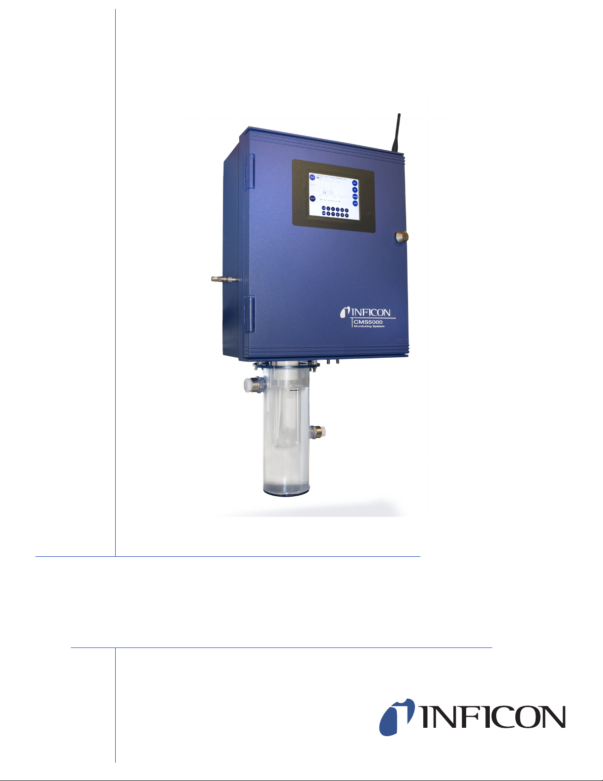
CMS5000 (shown in water sampling configuration)
CMS5000
Monitoring System
IPN 074-508-P1C
Page 2

Page 3

www.inficon.com reachus@inficon.com
Due to our continuing program of product improvements, specifications are subject to change without notice.
©2009 INFICON
TM
OPERATING MANUAL
CMS5000
Monitoring Syst
IPN 074-508-P1C
em
Page 4

Trademarks
The trademarks of the products mentioned in this manual are held by the companies that
produce them.
INFICON® is a registered trademark of INFICON.
SWAGELOK® is a registered trademark of Swagelok Co.
Tygon® is a registered trademark of Saint-Gobain Performance Plastics.
Teflon® and Tedlar® are registered trademarks of Dupont.
PEEK™ is a trademark of Victrex plc.
Fischer Connectors® is a registered trademark of Fischer Connectors SA.
All other brand and product names are trademarks or registered trademarks of their respective companies.
Disclaimer
The information contained in this manual is believed to be accurate and reliable. However, INFICON assumes
no responsibility for its use and shall not be liable for any special, incidental, or consequential damages related
to the use of this product.
Due to our continuous improvement program, specifications are subject to change without notice.
While photos are believed to be accurate and reliable, slight variations in equipment or software may occur.
Copyright
©2009 All rights reserved.
Reproduction or adaptation of any part of this document without permission is unlawful.
Page 5
Page 6
Page 7

Warranty
www.inficon.com reachus@inficon.com
INFICON warrants that the products sold by it are delivered free from any
defect in materials, workmanship and construction, and meet the products'
specifications set forth by INFICON.
INFICON warrants the products for one (1) year from the date of shipping
invoice of the products to the customer. The warranty excludes carrier gas,
GC columns, concentrator tubes, and all other items deemed by INFICON as
consumables. In the event the customer finds any defective products which do
not meet the aforesaid warranty, it shall give notice to that effect to INFICON.
The customer will return defective systems, accessories and parts to be
repaired to INFICON or INFICON contracted suppliers after obtaining a Return
Material Authorization (RMA) from INFICON Service Department.
INFICON liability under this warranty is limited to such products as are
returned, transportation prepaid, to INFICON plant no later than thirty (30)
days after the expiration of the warranty coverage and are found by INFICON
examination to have failed because of defective workmanship. At INFICON
election, it may either repair and return the product, or furnish a replacement
product, with transportation paid by INFICON in either case.
This warranty is made and accepted in lieu of all other warranties, express or
implied, whether of merchantability or of fitness for a particular purpose or
otherwise, as buyer's exclusive remedy for any defects in the product sold
hereunder. All other obligations and liabilities of INFICON, whether in contract
or tort (including negligence) or otherwise, are expressly excluded. In no event
shall INFICON be liable for any costs, expenses or damages, whether direct
or indirect, on any claim of defective product, in excess of the price paid by the
buyer for the products plus return transportation charges prepaid.
No warranty is made by INFICON for any INFICON product which has been
installed, used or operated contrary to INFICON written instruction manual or
which has been subject to misuse, negligence or accident, or has been
repaired or altered by anyone other than INFICON or which has been used in
a manner or for a purpose for which the product was not designed.
Page 8

Page 9

Chapter 1
1.1 Introduction. . . . . . . . . . . . . . . . . . . . . . . . . . . . . . . . . . . . . . . . . . . . . . . . . .1-1
1.2 Gas Chromatograph . . . . . . . . . . . . . . . . . . . . . . . . . . . . . . . . . . . . . . . . . . . 1-2
1.3 Micro Argon Ionization Detector (MAID). . . . . . . . . . . . . . . . . . . . . . . . . . . . 1-2
1.4 Radioactive Source . . . . . . . . . . . . . . . . . . . . . . . . . . . . . . . . . . . . . . . . . . . 1-3
1.5 Definition of Note, Hint, Danger, Warning
Chapter 2
2.1 Gas Chromatograph Specifications . . . . . . . . . . . . . . . . . . . . . . . . . . . . . . . 2-1
2.2 MAID - Micro Argon Ionization Detector . . . . . . . . . . . . . . . . . . . . . . . . . . . . 2-1
2.3 Communication. . . . . . . . . . . . . . . . . . . . . . . . . . . . . . . . . . . . . . . . . . . . . . .2-1
2.4 Physical Operating Requirements . . . . . . . . . . . . . . . . . . . . . . . . . . . . . . . . 2-2
2.5 Analysis and Protocols . . . . . . . . . . . . . . . . . . . . . . . . . . . . . . . . . . . . . . . . . 2-2
CMS5000 Operating Manual
Table Of Contents
Introduction
and Caution Paragraphs. . . . . . . . . . . . . . . . . . . . . . . . . . . . . . . . . . . . . . . .1-4
Specifications
Chapter 3
System Setup
3.1 CMS5000 Feature Options. . . . . . . . . . . . . . . . . . . . . . . . . . . . . . . . . . . . . .3-1
3.1.1 Analytical Unit. . . . . . . . . . . . . . . . . . . . . . . . . . . . . . . . . . . . . . . . . . . . . . . .3-1
3.1.2 Sampling Source . . . . . . . . . . . . . . . . . . . . . . . . . . . . . . . . . . . . . . . . . . . . . 3-1
3.1.3 Integration. . . . . . . . . . . . . . . . . . . . . . . . . . . . . . . . . . . . . . . . . . . . . . . . . . .3-1
3.1.4 Ship Kits . . . . . . . . . . . . . . . . . . . . . . . . . . . . . . . . . . . . . . . . . . . . . . . . . . . . 3-1
3.1.5 Laptop PC with CMS IQ Software . . . . . . . . . . . . . . . . . . . . . . . . . . . . . . . . 3-1
3.2 CMS5000 Ship Kit Contents. . . . . . . . . . . . . . . . . . . . . . . . . . . . . . . . . . . . .3-2
3.3 CMS5000 Diagram . . . . . . . . . . . . . . . . . . . . . . . . . . . . . . . . . . . . . . . . . . . . 3-2
IPN 074-508-P1C
3.4 Mounting Instructions . . . . . . . . . . . . . . . . . . . . . . . . . . . . . . . . . . . . . . . . . . 3-3
3.5 Water Monitoring Assembly Instructions . . . . . . . . . . . . . . . . . . . . . . . . . . . 3-5
3.6 Attaching the Water Sampling Vessel . . . . . . . . . . . . . . . . . . . . . . . . . . . . . 3-7
3.7 Connecting the Water Supply. . . . . . . . . . . . . . . . . . . . . . . . . . . . . . . . . . . .3-8
3.8 Air Monitoring Assembly Instructions . . . . . . . . . . . . . . . . . . . . . . . . . . . . . . 3-8
3.8.1 Ambient Air Sampling. . . . . . . . . . . . . . . . . . . . . . . . . . . . . . . . . . . . . . . . . . 3-9
3.8.2 Air Line Sampling . . . . . . . . . . . . . . . . . . . . . . . . . . . . . . . . . . . . . . . . . . . . 3-10
3.9 Connecting the Argon Supply. . . . . . . . . . . . . . . . . . . . . . . . . . . . . . . . . . . 3-12
3.10 Connecting the Power Supply . . . . . . . . . . . . . . . . . . . . . . . . . . . . . . . . . . 3-13
3.11 Communication Configuration . . . . . . . . . . . . . . . . . . . . . . . . . . . . . . . . . . 3-14
3.11.1 Ethernet . . . . . . . . . . . . . . . . . . . . . . . . . . . . . . . . . . . . . . . . . . . . . . . . . . .3-14
3.11.2 I/O. . . . . . . . . . . . . . . . . . . . . . . . . . . . . . . . . . . . . . . . . . . . . . . . . . . . . . . .3-14
TOC - 1
Page 10

Chapter 4
4.1 Introduction. . . . . . . . . . . . . . . . . . . . . . . . . . . . . . . . . . . . . . . . . . . . . . . . . . 4-1
4.1.1 Setting Up Laptop Communications. . . . . . . . . . . . . . . . . . . . . . . . . . . . . . . 4-1
4.1.2 Configuring the CMS5000 for Laptop Communications. . . . . . . . . . . . . . . . 4-4
Chapter 5
5.1 Software Setup. . . . . . . . . . . . . . . . . . . . . . . . . . . . . . . . . . . . . . . . . . . . . . . 5-1
5.2 Calibrating the Check Standard . . . . . . . . . . . . . . . . . . . . . . . . . . . . . . . . . . 5-1
5.3 Calibrating the Water or Air Purge Methods. . . . . . . . . . . . . . . . . . . . . . . . . 5-9
5.4 FTP Connection . . . . . . . . . . . . . . . . . . . . . . . . . . . . . . . . . . . . . . . . . . . . . 5-10
5.5 System Integration . . . . . . . . . . . . . . . . . . . . . . . . . . . . . . . . . . . . . . . . . . . 5-20
5.6 Setting Startup Methods. . . . . . . . . . . . . . . . . . . . . . . . . . . . . . . . . . . . . . . 5-20
5.7 Input Methods. . . . . . . . . . . . . . . . . . . . . . . . . . . . . . . . . . . . . . . . . . . . . . . 5-23
5.8 Method Sequence . . . . . . . . . . . . . . . . . . . . . . . . . . . . . . . . . . . . . . . . . . . 5-25
CMS5000 Operating Manual
Setting Up Laptop Communication
Software Setup
Chapter 6
6.1 Introduction. . . . . . . . . . . . . . . . . . . . . . . . . . . . . . . . . . . . . . . . . . . . . . . . . . 6-1
6.2 SYS Option. . . . . . . . . . . . . . . . . . . . . . . . . . . . . . . . . . . . . . . . . . . . . . . . . . 6-1
6.3 TIME Option . . . . . . . . . . . . . . . . . . . . . . . . . . . . . . . . . . . . . . . . . . . . . . . . . 6-2
6.4 NET Option. . . . . . . . . . . . . . . . . . . . . . . . . . . . . . . . . . . . . . . . . . . . . . . . . . 6-2
6.5 STAT Option. . . . . . . . . . . . . . . . . . . . . . . . . . . . . . . . . . . . . . . . . . . . . . . . . 6-3
6.6 FIRM Option . . . . . . . . . . . . . . . . . . . . . . . . . . . . . . . . . . . . . . . . . . . . . . . . . 6-3
Chapter 7
7.1 Introduction. . . . . . . . . . . . . . . . . . . . . . . . . . . . . . . . . . . . . . . . . . . . . . . . . . 7-1
7.2 Default Methods . . . . . . . . . . . . . . . . . . . . . . . . . . . . . . . . . . . . . . . . . . . . . . 7-1
7.3 System Calibration Standard . . . . . . . . . . . . . . . . . . . . . . . . . . . . . . . . . . . . 7-1
7.4 Operating the CMS5000 using the Front Panel . . . . . . . . . . . . . . . . . . . . . . 7-1
Chapter 8
8.1 Review Data . . . . . . . . . . . . . . . . . . . . . . . . . . . . . . . . . . . . . . . . . . . . . . . . . 8-1
Status Button
Operation
IPN 074-508-P1C
Review Data
TOC - 2
Page 11

CMS5000 Operating Manual
Chapter 9
System Option
9.1 Introduction. . . . . . . . . . . . . . . . . . . . . . . . . . . . . . . . . . . . . . . . . . . . . . . . . .9-1
9.2 System Option . . . . . . . . . . . . . . . . . . . . . . . . . . . . . . . . . . . . . . . . . . . . . . . 9-1
9.3 Set Date, Time and Time Zone . . . . . . . . . . . . . . . . . . . . . . . . . . . . . . . . . . 9-3
9.3.1 Set Network Info . . . . . . . . . . . . . . . . . . . . . . . . . . . . . . . . . . . . . . . . . . . . . . 9-7
9.3.2 Set Language . . . . . . . . . . . . . . . . . . . . . . . . . . . . . . . . . . . . . . . . . . . . . . . 9-10
Chapter 10
Exit Option
10.1 Exit Options . . . . . . . . . . . . . . . . . . . . . . . . . . . . . . . . . . . . . . . . . . . . . . . . 10-1
10.2 Accessing Exit Options. . . . . . . . . . . . . . . . . . . . . . . . . . . . . . . . . . . . . . . .10-1
10.3 Restart System . . . . . . . . . . . . . . . . . . . . . . . . . . . . . . . . . . . . . . . . . . . . . .10-3
10.4 Reboot System . . . . . . . . . . . . . . . . . . . . . . . . . . . . . . . . . . . . . . . . . . . . . .10-4
10.5 Return to Main Menu . . . . . . . . . . . . . . . . . . . . . . . . . . . . . . . . . . . . . . . . .10-4
Chapter 11
CMS IQ System Setup
11.1 Introduction. . . . . . . . . . . . . . . . . . . . . . . . . . . . . . . . . . . . . . . . . . . . . . . . .11-1
11.2 System Setup . . . . . . . . . . . . . . . . . . . . . . . . . . . . . . . . . . . . . . . . . . . . . . . 11-1
11.2.1 System Setup Menu . . . . . . . . . . . . . . . . . . . . . . . . . . . . . . . . . . . . . . . . . .11-2
11.2.2 File Menu . . . . . . . . . . . . . . . . . . . . . . . . . . . . . . . . . . . . . . . . . . . . . . . . . .11-2
11.2.2.1 Generate Trend Report . . . . . . . . . . . . . . . . . . . . . . . . . . . . . . . . . . . . . . . 11-3
11.2.3 Functions Menu . . . . . . . . . . . . . . . . . . . . . . . . . . . . . . . . . . . . . . . . . . . . .11-7
11.2.4 System . . . . . . . . . . . . . . . . . . . . . . . . . . . . . . . . . . . . . . . . . . . . . . . . . . . . 11-8
11.2.4.1 Port Settings Tab . . . . . . . . . . . . . . . . . . . . . . . . . . . . . . . . . . . . . . . . . . . .11-9
11.2.4.2 Display Tab. . . . . . . . . . . . . . . . . . . . . . . . . . . . . . . . . . . . . . . . . . . . . . . . 11-10
11.2.4.3 Miscellaneous Tab . . . . . . . . . . . . . . . . . . . . . . . . . . . . . . . . . . . . . . . . . . 11-11
11.2.5 Tools Menu. . . . . . . . . . . . . . . . . . . . . . . . . . . . . . . . . . . . . . . . . . . . . . . .11-18
IPN 074-508-P1C
11.2.5.1 Set Access Level . . . . . . . . . . . . . . . . . . . . . . . . . . . . . . . . . . . . . . . . . . .11-18
11.2.5.1.1 Changing Access Levels . . . . . . . . . . . . . . . . . . . . . . . . . . . . . . . . . . . . .11-19
11.2.5.1.2 Setting or Changing the Access Level Password. . . . . . . . . . . . . . . . . . . 11-20
11.2.6 View Menu . . . . . . . . . . . . . . . . . . . . . . . . . . . . . . . . . . . . . . . . . . . . . . . .11-21
11.2.7 Window Menu. . . . . . . . . . . . . . . . . . . . . . . . . . . . . . . . . . . . . . . . . . . . . .11-22
11.2.8 Help Menu . . . . . . . . . . . . . . . . . . . . . . . . . . . . . . . . . . . . . . . . . . . . . . . . 11-23
11.3 System Setup Icons . . . . . . . . . . . . . . . . . . . . . . . . . . . . . . . . . . . . . . . . . 11-23
11.4 Safety DB . . . . . . . . . . . . . . . . . . . . . . . . . . . . . . . . . . . . . . . . . . . . . . . . . 11-26
11.5 Manage Files . . . . . . . . . . . . . . . . . . . . . . . . . . . . . . . . . . . . . . . . . . . . . .11-30
11.6 Status Icon . . . . . . . . . . . . . . . . . . . . . . . . . . . . . . . . . . . . . . . . . . . . . . . . 11-34
11.6.1 Status Properties . . . . . . . . . . . . . . . . . . . . . . . . . . . . . . . . . . . . . . . . . . .11-35
TOC - 3
Page 12

CMS5000 Operating Manual
11.6.2 CMS5000 Time Zone . . . . . . . . . . . . . . . . . . . . . . . . . . . . . . . . . . . . . . . . 11-36
11.6.3 CMS5000 Information . . . . . . . . . . . . . . . . . . . . . . . . . . . . . . . . . . . . . . . 11-40
11.6.4 Pressure Flows and Temperatures . . . . . . . . . . . . . . . . . . . . . . . . . . . . . 11-41
11.6.5 Input/Output . . . . . . . . . . . . . . . . . . . . . . . . . . . . . . . . . . . . . . . . . . . . . . . 11-44
11.6.6 Data Settings . . . . . . . . . . . . . . . . . . . . . . . . . . . . . . . . . . . . . . . . . . . . . . 11-45
11.6.7 Functions . . . . . . . . . . . . . . . . . . . . . . . . . . . . . . . . . . . . . . . . . . . . . . . . . 11-48
11.6.8 Parameters. . . . . . . . . . . . . . . . . . . . . . . . . . . . . . . . . . . . . . . . . . . . . . . . 11-49
11.7 Front Panel Display Icon . . . . . . . . . . . . . . . . . . . . . . . . . . . . . . . . . . . . . 11-54
11.8 CMS5000 Sensor Status Icon . . . . . . . . . . . . . . . . . . . . . . . . . . . . . . . . . 11-55
11.8.1 Update CMS5000 Software . . . . . . . . . . . . . . . . . . . . . . . . . . . . . . . . . . . 11-55
11.8.2 Bring Online . . . . . . . . . . . . . . . . . . . . . . . . . . . . . . . . . . . . . . . . . . . . . . . 11-56
11.8.2.1 Communication Messages . . . . . . . . . . . . . . . . . . . . . . . . . . . . . . . . . . . . 11-56
11.8.3 Disconnect . . . . . . . . . . . . . . . . . . . . . . . . . . . . . . . . . . . . . . . . . . . . . . . . 11-56
Chapter 12
Data Review Screen
12.1 Introduction to Data Review . . . . . . . . . . . . . . . . . . . . . . . . . . . . . . . . . . . . 12-1
12.2 Accessing the Data Review Feature . . . . . . . . . . . . . . . . . . . . . . . . . . . . . 12-1
12.3 Menus. . . . . . . . . . . . . . . . . . . . . . . . . . . . . . . . . . . . . . . . . . . . . . . . . . . . . 12-3
12.3.1 Data Review Menu . . . . . . . . . . . . . . . . . . . . . . . . . . . . . . . . . . . . . . . . . . . 12-3
12.4 Data Review Toolbar . . . . . . . . . . . . . . . . . . . . . . . . . . . . . . . . . . . . . . . . . 12-4
12.5 Data File Information Window . . . . . . . . . . . . . . . . . . . . . . . . . . . . . . . . . . 12-5
12.6 Reports. . . . . . . . . . . . . . . . . . . . . . . . . . . . . . . . . . . . . . . . . . . . . . . . . . . . 12-6
12.6.1 Access Reports . . . . . . . . . . . . . . . . . . . . . . . . . . . . . . . . . . . . . . . . . . . . . 12-6
12.6.2 Summary Reports . . . . . . . . . . . . . . . . . . . . . . . . . . . . . . . . . . . . . . . . . . . 12-7
12.6.3 Quantitative Reports. . . . . . . . . . . . . . . . . . . . . . . . . . . . . . . . . . . . . . . . . . 12-7
12.7 Chromatogram Window Options . . . . . . . . . . . . . . . . . . . . . . . . . . . . . . . . 12-9
12.7.1 Manual Scale . . . . . . . . . . . . . . . . . . . . . . . . . . . . . . . . . . . . . . . . . . . . . . . 12-9
12.7.2 View All Data . . . . . . . . . . . . . . . . . . . . . . . . . . . . . . . . . . . . . . . . . . . . . . 12-12
12.7.3 View Temperature Profile. . . . . . . . . . . . . . . . . . . . . . . . . . . . . . . . . . . . . 12-13
12.7.4 Change Plot Color . . . . . . . . . . . . . . . . . . . . . . . . . . . . . . . . . . . . . . . . . . 12-14
12.7.5 Peaks . . . . . . . . . . . . . . . . . . . . . . . . . . . . . . . . . . . . . . . . . . . . . . . . . . . . 12-15
12.7.5.1 Search for Peaks . . . . . . . . . . . . . . . . . . . . . . . . . . . . . . . . . . . . . . . . . . . 12-15
IPN 074-508-P1C
12.7.5.1.1 Add Peaks . . . . . . . . . . . . . . . . . . . . . . . . . . . . . . . . . . . . . . . . . . . . . . . . 12-16
12.7.5.1.2 Peak Search Parameters . . . . . . . . . . . . . . . . . . . . . . . . . . . . . . . . . . . . . 12-17
12.7.5.1.3 Redo Peak Search . . . . . . . . . . . . . . . . . . . . . . . . . . . . . . . . . . . . . . . . . . 12-17
12.7.5.1.4 Report Preview. . . . . . . . . . . . . . . . . . . . . . . . . . . . . . . . . . . . . . . . . . . . . 12-17
12.7.5.2 Show/Update Current Peaks . . . . . . . . . . . . . . . . . . . . . . . . . . . . . . . . . . 12-18
12.7.5.3 Edit Base Points . . . . . . . . . . . . . . . . . . . . . . . . . . . . . . . . . . . . . . . . . . . . 12-18
12.7.5.4 Clear the Peaks . . . . . . . . . . . . . . . . . . . . . . . . . . . . . . . . . . . . . . . . . . . . 12-20
TOC - 4
Page 13

CMS5000 Operating Manual
12.7.5.5 Label the Peaks . . . . . . . . . . . . . . . . . . . . . . . . . . . . . . . . . . . . . . . . . . . .12-21
12.7.5.6 Change Search Parameters . . . . . . . . . . . . . . . . . . . . . . . . . . . . . . . . . . .12-21
12.7.5.7 Previous Search Results . . . . . . . . . . . . . . . . . . . . . . . . . . . . . . . . . . . . .12-22
12.7.6 Control Panel . . . . . . . . . . . . . . . . . . . . . . . . . . . . . . . . . . . . . . . . . . . . . .12-24
12.7.7 Properties . . . . . . . . . . . . . . . . . . . . . . . . . . . . . . . . . . . . . . . . . . . . . . . . . 12-25
12.8 How to Access the Scan Cursor. . . . . . . . . . . . . . . . . . . . . . . . . . . . . . . .12-25
12.9 Using the Zoom Function . . . . . . . . . . . . . . . . . . . . . . . . . . . . . . . . . . . . . 12-26
12.10 Range Tool. . . . . . . . . . . . . . . . . . . . . . . . . . . . . . . . . . . . . . . . . . . . . . . . 12-31
12.10.1 Selecting a Background . . . . . . . . . . . . . . . . . . . . . . . . . . . . . . . . . . . . . .12-34
Chapter 13
Run Method
13.1 Run Method Procedure . . . . . . . . . . . . . . . . . . . . . . . . . . . . . . . . . . . . . . . 13-1
Chapter 14
Chromatogram Overlay
14.1 Introduction. . . . . . . . . . . . . . . . . . . . . . . . . . . . . . . . . . . . . . . . . . . . . . . . .14-1
14.2 Chromatogram Overlay . . . . . . . . . . . . . . . . . . . . . . . . . . . . . . . . . . . . . . .14-1
14.3 Chromatogram Subtract . . . . . . . . . . . . . . . . . . . . . . . . . . . . . . . . . . . . . . . 14-4
Chapter 15
Method Editor
15.1 The Method Editor . . . . . . . . . . . . . . . . . . . . . . . . . . . . . . . . . . . . . . . . . . .15-1
15.2 Accessing Method Editor . . . . . . . . . . . . . . . . . . . . . . . . . . . . . . . . . . . . . .15-3
15.3 Description Page . . . . . . . . . . . . . . . . . . . . . . . . . . . . . . . . . . . . . . . . . . . . 15-3
15.4 Startup . . . . . . . . . . . . . . . . . . . . . . . . . . . . . . . . . . . . . . . . . . . . . . . . . . . .15-5
15.4.1 CMS5000 Temperatures (C) . . . . . . . . . . . . . . . . . . . . . . . . . . . . . . . . . . . 15-6
15.4.2 Method Type Selection. . . . . . . . . . . . . . . . . . . . . . . . . . . . . . . . . . . . . . . .15-6
15.5 Inlet. . . . . . . . . . . . . . . . . . . . . . . . . . . . . . . . . . . . . . . . . . . . . . . . . . . . . . .15-6
IPN 074-508-P1C
15.5.1 Inlet States . . . . . . . . . . . . . . . . . . . . . . . . . . . . . . . . . . . . . . . . . . . . . . . . . 15-7
15.5.2 GC Temperature Profile . . . . . . . . . . . . . . . . . . . . . . . . . . . . . . . . . . . . . . 15-11
15.5.3 Scan Events . . . . . . . . . . . . . . . . . . . . . . . . . . . . . . . . . . . . . . . . . . . . . . . 15-12
15.6 Search Page. . . . . . . . . . . . . . . . . . . . . . . . . . . . . . . . . . . . . . . . . . . . . . .15-13
15.6.1 Setting Up a Quantitative Search . . . . . . . . . . . . . . . . . . . . . . . . . . . . . . . 15-14
15.7 Data Page. . . . . . . . . . . . . . . . . . . . . . . . . . . . . . . . . . . . . . . . . . . . . . . . . 15-16
15.7.1 Data File Information . . . . . . . . . . . . . . . . . . . . . . . . . . . . . . . . . . . . . . . . 15-16
15.7.2 Date and Time Appendix . . . . . . . . . . . . . . . . . . . . . . . . . . . . . . . . . . . . .15-17
15.7.3 Use Default Directory . . . . . . . . . . . . . . . . . . . . . . . . . . . . . . . . . . . . . . . . 15-19
15.7.4 Data Display . . . . . . . . . . . . . . . . . . . . . . . . . . . . . . . . . . . . . . . . . . . . . . .15-19
15.8 Summary Page. . . . . . . . . . . . . . . . . . . . . . . . . . . . . . . . . . . . . . . . . . . . .15-20
15.9 Saving a Method. . . . . . . . . . . . . . . . . . . . . . . . . . . . . . . . . . . . . . . . . . . . 15-21
TOC - 5
Page 14

Chapter 16
16.1 Introduction To Quantitative Analysis. . . . . . . . . . . . . . . . . . . . . . . . . . . . . 16-1
16.2 Using the Calibrate Function . . . . . . . . . . . . . . . . . . . . . . . . . . . . . . . . . . . 16-2
16.3 Glossary of Terms in the Calibrate Window . . . . . . . . . . . . . . . . . . . . . . . 16-17
16.3.1 Method . . . . . . . . . . . . . . . . . . . . . . . . . . . . . . . . . . . . . . . . . . . . . . . . . . . 16-17
16.3.2 Data Files . . . . . . . . . . . . . . . . . . . . . . . . . . . . . . . . . . . . . . . . . . . . . . . . . 16-18
16.3.3 Peak Search Section . . . . . . . . . . . . . . . . . . . . . . . . . . . . . . . . . . . . . . . . 16-19
16.3.4 Calibrate Options . . . . . . . . . . . . . . . . . . . . . . . . . . . . . . . . . . . . . . . . . . . 16-19
16.3.5 Analytes . . . . . . . . . . . . . . . . . . . . . . . . . . . . . . . . . . . . . . . . . . . . . . . . . . 16-19
16.3.6 View Reports . . . . . . . . . . . . . . . . . . . . . . . . . . . . . . . . . . . . . . . . . . . . . . 16-20
16.3.7 Calibrate Display . . . . . . . . . . . . . . . . . . . . . . . . . . . . . . . . . . . . . . . . . . . 16-21
Appendix A
A.1 Introduction. . . . . . . . . . . . . . . . . . . . . . . . . . . . . . . . . . . . . . . . . . . . . . . . . .A-1
A.2 CMS5000API.H . . . . . . . . . . . . . . . . . . . . . . . . . . . . . . . . . . . . . . . . . . . . . .A-1
CMS5000 Operating Manual
Creating Calibration Libraries
Ethernet Integration
TOC - 6
IPN 074-508-P1C
Page 15
1.1 Introduction
WARNING
Partition Coefficient
VOC
water
VOC
gas
------------------------=
The CMS5000 Monitoring System provides online water or air monitoring for the
detection and analysis of VOCs. The programmable sample collection system
allows for on-site, rapid analysis of current air or water conditions without the need
for pre-treatment or filtration.
CMS5000 Operating Manual
Chapter 1
Introduction
Due to U.S. Nuclear Regulatory Commission regulations,
the CMS5000 oven, which contains a sealed radioactive
source, may not be repaired by unauthorized personnel.
INFICON will provide the maintenance, repair,
replacement and disposal of the radioactive source, as
well as any part of the detector.
For water analysis, VOCs are purged from the water flowing through the water
vessel. Argon will bubble into the water, the gas bubbles will rise through the water
and collect at the top of the collection tube. As the bubbles rise, a portion of the
VOCs will pass from the water phase to the gas phase — this is known as
"partitioning". The ratio of the VOC concentration in the water phase, VOC
the concentration in the gas phase, VOC
equation [1].
IPN 074-508-P1C
Each compound will partition according to its solubility in water, its vapor pressure,
the specific water sampling matrix and the temperature. The quantity of VOCs
detected is dependent on the partition coefficient. In general, highly polar
compounds are more readily detected than less polar compounds.
A permeation tube that contains toluene is used as a check standard to ensure
proper system calibration and verify sample integrity. It will compensate for normal
fluctuations in the column, the concentrator and detector sensitivity. The lifetime of
the permeation tube is approximately 8 years.
After collection, the VOCs from the air or water samples are drawn into the
CMS5000 with the internal pump and adsorbed by the concentrator. The VOCs are
then desorbed into the column of the gas chromatograph by heating the
concentrator and reversing the carrier gas flow.
, is the partition coefficient. See
gas
water,
to
[1]
1 - 1
Page 16

CMS5000 Operating Manual
1.2 Gas Chromatograph
The gas chromatograph (GC) performs a time separation of the sample
compounds. The separation order is primarily based on increasing compound
boiling point.
Argon is used as the carrier gas to transport analytes through a 100%
dimethylpolysiloxane, 0.32 mm id, 30 M, 4.0 µm (or equivalent) column. The inside
of the column is coated with a thin layer of material known as the stationary phase.
The stationary phase selectively attracts components in a sample mixture. The
mixture of sample compounds in the argon gas, also known as the mobile phase,
interact with the chemicals of the stationary phase. The chemicals which spend the
least time partitioned in the column will elute (exit) off the column first.
The time taken by an individual compound to travel into the system until the
compound elutes from the column is referred to as the retention time (RT). If the
GC conditions remain constant, the same compound will elute from the column at
nearly the same retention time for each injection.
The performance of the column is affected by temperature, therefore, the column
is housed in a temperature controlled oven. The oven is programmed to increase
the temperature gradually (called ramping) to improve compound separation while
decreasing analysis time. As the temperature increases, the compounds with the
lowest boiling points will elute first with the standard non-polar phase coated
column installed.
A chromatogram of eluting organic gases from the gas chromatograph is plotted as
a function of time from the injection the compound mixture. The chromatogram
depicts the separation of the various compounds from each other by the action of
the gas chromatograph, as described above.
1.3 Micro Argon Ionization Detector (MAID)
The Micro Argon Ionization Detector (MAID) is sensitive to organic compounds
having an ionization potential of 11.7 eV or lower, which includes halomethanes,
haloethanes, carbon tetrachloride and 1,1,1-trichloroethane. The CMS5000 can
detect these compounds, as well as other hydrocarbons, to parts-per trillion (PPT)
levels.
The MAID uses argon as a carrier gas. When argon flows over a nickel-63 (Ni-63)
source, argon atoms are energized to an excited, metastable state, while other
argon atoms are ionized. The excitation energy of argon is approximately 11.7 eV.
Ar
Ar* (Energized to excited state)
IPN 074-508-P1C
1 - 2
Page 17

When an organic molecule (R) enters the detector, it collides with the metastable
WARNING
argon (Ar*). During this collision, energy is released to the organic molecule. Since
the ionization potential of most organic compounds is less than 11.7 eV, the
metastable argon atoms will ionize them, producing positive ions and electrons.
The reaction is illustrated as follows:
Ar* + R
Ar + R + e
High voltage applied across the detector produces a current, which is amplified and
measured to produce a chromatogram.
1.4 Radioactive Source
The MAID in the CMS5000 contains a radioactive isotope in a solid form of Ni-63,
with an activity level of up to 2.4 millicuries. The half-life of Ni-63 is approximately
96 years. The source of the radioactivity is sealed within a stainless steel cylinder
which is located within the detector cavity. Per New York State radioactive materials
license regulations, a wipe test is required for the Ni-63 source every 36 months.
The first test is completed at the factory prior to shipment.
CMS5000 Operating Manual
-
No repair of the detector cell should be performed by the
user. If the detector cell does not exhibit an electronic
signal, the isotope may require replacement. Contact
INFICON for repair or replacement of the detector cell.
The State of New York Department of Labor, Division of Safety and Health and the
United States Nuclear Regulatory Commission under either a Specific License or a
General License authorizes possession and use of the radioactive source in the
instrument. A copy of the terms and requirements of a General Licensee (section
12 NYCRR, part 38:41, table 3, item b) accompanied INFICON transfer of this
instrument. The safety requirements of the Specific License or General License are
designed to protect the user and the public from unnecessary prolonged exposure
IPN 074-508-P1C
to radiation. Following these requirements is imperative.
1 - 3
Page 18
CMS5000 Operating Manual
WARNING
WARNING - Risk Of Electric Shock
CAUTION
1.5 Definition of Note, Hint, Danger, Warning and Caution Paragraphs
NOTE: This is a note paragraph. Notes provide additional information about the
current topic.
HINT: This is a hint paragraph. Hints provide insight into product usage
This is a Warning paragraph. It warns of actions that may
cause physical injury.
This Warning paragraph warns of the presence of
electrical voltages which may cause physical injury.
This is a Caution paragraph. It cautions against actions
which may damage the instrument or lead to the loss of
data.
IPN 074-508-P1C
1 - 4
Page 19

2.1 Gas Chromatograph Specifications
Column . . . . . . . . . . . . . . . . . . . . . . . 100% dimethylpolysiloxane, 0.32 mm id,
4.0
µm df or equivalent
Valves . . . . . . . . . . . . . . . . . . . . . . . . Stainless Steel body/Teflon diaphragm
Temperature Programmable
Column Module . . . . . . . . . . . . . . . . 55-200
Carrier Gas. . . . . . . . . . . . . . . . . . . . Argon 99.9999% @ 414-689 kPa
(60-100 psi)
Variable Column Pressure Control . . Regulator pre-set to 90 psi
Sample Inlet . . . . . . . . . . . . . . . . . . . Water Vessel with purge-and-trap SituProbe
Air Sampling Tube
CMS5000 Operating Manual
Chapter 2
Specifications
°C
2.2 MAID - Micro Argon Ionization Detector
Temperature . . . . . . . . . . . . . . . . . . . Maximum 110°C
Sensitivity . . . . . . . . . . . . . . . . . . . . . 0.5 ppb Benzene in water, s/n > 200:1
0.5 ppb MTBE in water, s/n > 15:1
Detection Limit . . . . . . . . . . . . . . . . . PPB- PPT in air
Dynamic Range . . . . . . . . . . . . . . . . 3 decades
Stability . . . . . . . . . . . . . . . . . . . . . . . 5 runs of 5 ppb Benzene in air and water:
RSD calculated <15%
Radioactive Source . . . . . . . . . . . . . 2.4 mCi Ni-63
IPN 074-508-P1C
2.3 Communication
Integration . . . . . . . . . . . . . . . . . . . . TCP/IP based
USB for local diagnostics
I/O Relay Contacts
FTP. . . . . . . . . . . . . . . . . . . . . . . . . . Configurable for automated data upload
Storage/Archival . . . . . . . . . . . . . . . . 16 GB Flash Drive
System Status . . . . . . . . . . . . . . . . . Status table for system operating changes
Wireless Connectivity . . . . . . . . . . . . 802.11 B/G
Optional Touch Screen . . . . . . . . . . . 6.5" VGA color display with touch screen
2 - 1
Page 20

CMS5000 Operating Manual
2.4 Physical Operating Requirements
Size . . . . . . . . . . . . . . . . . . . . . . . . . 16.9 in x 32.7 in x 10.2 in
(43 cm x 83 cm x 26 cm)
Weight . . . . . . . . . . . . . . . . . . . . . . . 55.1 lb (25 kg)
Power . . . . . . . . . . . . . . . . . . . . . . . . 120-240 V(ac)
Temperature . . . . . . . . . . . . . . . . . . . 5
2.5 Analysis and Protocols
Integrated Performance Standard . . Toluene permeation tube for check standard
Detectable Compounds . . . . . . . . . . Volatile organic compounds
Acceptance Protocol . . . . . . . . . . . . Initial setup with BTEX standard
Data Analysis . . . . . . . . . . . . . . . . . . Automatic peak detection and area
°C to 45°C (ambient and water
temperature)
calibration
(e.g. halogenated and non-halogenated
aliphatic and aromatic hydrocarbons, etc.)
integration for known compounds
2 - 2
IPN 074-508-P1C
Page 21

3.1 CMS5000 Feature Options
3.1.1 Analytical Unit
CMS5000 . . . . . . . . . . . . . . . . . . . . . . . . . . . . . . . . . . . . . . .935-600-G1
3.1.2 Sampling Source
Water, No Vessel . . . . . . . . . . . . . . . . . . . . . . . . . . . . . . . . .935-700-G1
Water, Standard Vessel . . . . . . . . . . . . . . . . . . . . . . . . . . . .935-700-G3
Air, Sampling System . . . . . . . . . . . . . . . . . . . . . . . . . . . . . . 935-701-G1
3.1.3 Integration
CMS5000 Operating Manual
Chapter 3
System Setup
Ethernet, 802.11g, Wireless . . . . . . . . . . . . . . . . . . . . . . . . .935-710-G1
I/O Relays and 3’ cable, Ethernet, and 802.11g Wireless . . 935-711-G1
3.1.4 Ship Kits
CMS5000 120 V (USA) . . . . . . . . . . . . . . . . . . . . . . . . . . . . 935-721-G1
CMS5000 230 V (European) . . . . . . . . . . . . . . . . . . . . . . . .935-721-G2
CMS5000 230 V (UK) . . . . . . . . . . . . . . . . . . . . . . . . . . . . .935-721-G3
CMS5000 230 V (China) . . . . . . . . . . . . . . . . . . . . . . . . . . . 935-721-G4
3.1.5 Laptop PC with CMS IQ Software
IPN 074-508-P1C
CMS IQ Software, No Laptop. . . . . . . . . . . . . . . . . . . . . . . .935-030-G1
Laptop w/CMS IQ Software (USA) . . . . . . . . . . . . . . . . . . . .935-731-G1
Laptop w/CMS IQ Software (European). . . . . . . . . . . . . . . .935-731-G2
Laptop w/CMS IQ Software (UK) . . . . . . . . . . . . . . . . . . . . .935-731-G3
Laptop w/CMS IQ Software (China) . . . . . . . . . . . . . . . . . . .935-731-G4
3 - 1
Page 22
CMS5000 Operating Manual
3.2 CMS5000 Ship Kit Contents
The Ship Kit will contain the following items:
Power Supply . . . . . . . . . . . . . . . . . . 930-469-P1 (110 V USA)
Ethernet Cable . . . . . . . . . . . . . . . . . 600-1319-P2
CMS5000 Operator Manual . . . . . . . 074-508-P1
Argon Tank Regulator . . . . . . . . . . . 935-412-P1
Argon Fill Line . . . . . . . . . . . . . . . . . 935-212-G1
Quick Disconnect Stem . . . . . . . . . . 059-0329
CMS5000 Training CD . . . . . . . . . . . 074-5020-G1
3.3 CMS5000 Diagram
930-469-G4 (230 V China)
930-469-P2 (230 V European)
930-469-G3 (230 V UK)
3 - 2
IPN 074-508-P1C
Page 23
3.4 Mounting Instructions
CAUTION
WARNING
Installation of the CMS5000 must be performed by an
INFICON authorized technician.
The CMS5000 Monitoring System is heavy. Use proper
saftey procedures and PPE when mounting the unit.
NOTE: After the CMS5000 has been powered on, the system should only be
operated with the door closed to ensure stability of heated internal
components
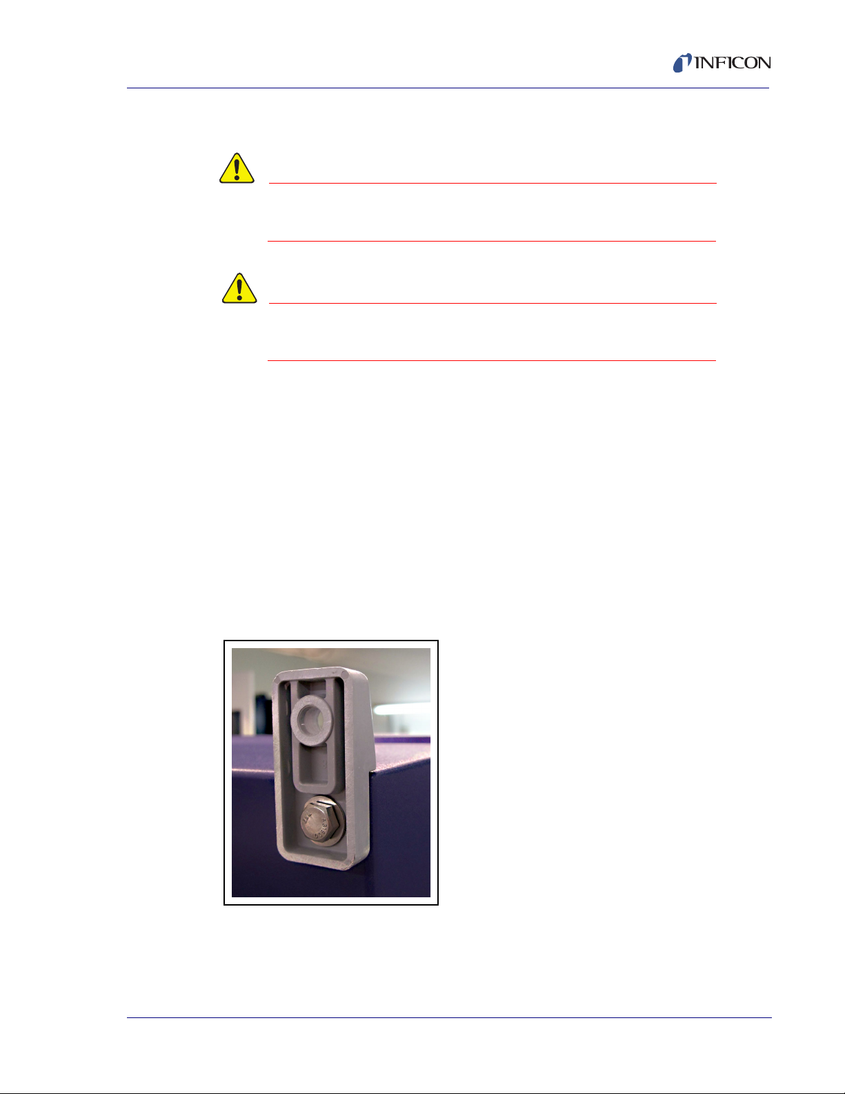
The CMS5000 Monitoring System requires mounting as well as some minor
assembly. The four mounting brackets included in the ship kit need to be attached
to the four corners on the back of the unit. Position the bracket on the analytical
module by lining up the openings in the bracket and on the unit. Place the washer
over the lag bolt and using a socket wrench, screw in the lag bolt until tight (see
page 5 of the instructions included with the hardware). See Figure 3-1.
CMS5000 Operating Manual
NOTE: The nuts included with the lag bolts are not needed to mount the brackets
to the unit.
Figure 3-1 Attaching the Mounting Brackets
IPN 074-508-P1C
Structural mounting hardware is not included. It is the responsibility of the user to
ensure that proper mounting hardware is used to support the weight of the
CMS5000, and (if the CMS5000 is to be used for continual online water monitoring)
3 - 3
Page 24
CMS5000 Operating Manual
the filled sampling vessel. The CMS5000 weighs 55.1 lbs. (25 kg). All plumbing to
and from the sampling vessel should be supported independently of the analytical
module, as the system design will not support any additional weight.
For air monitoring, the CMS5000 should be mounted in an optimal location for
collecting air samples of interest. Care should be exercised to avoid locations
affected by air currents from heating or cooling systems, doors, windows or
structural openings.
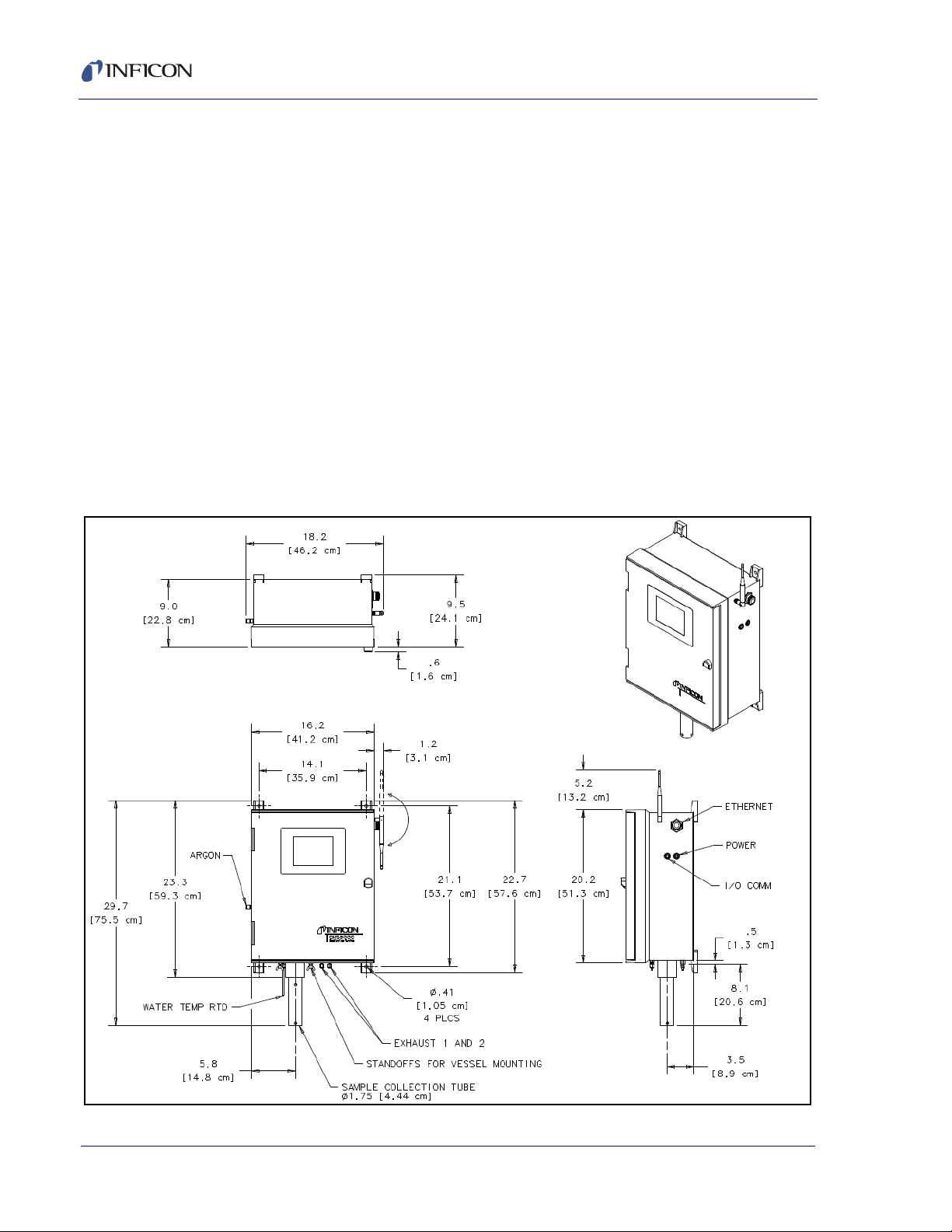
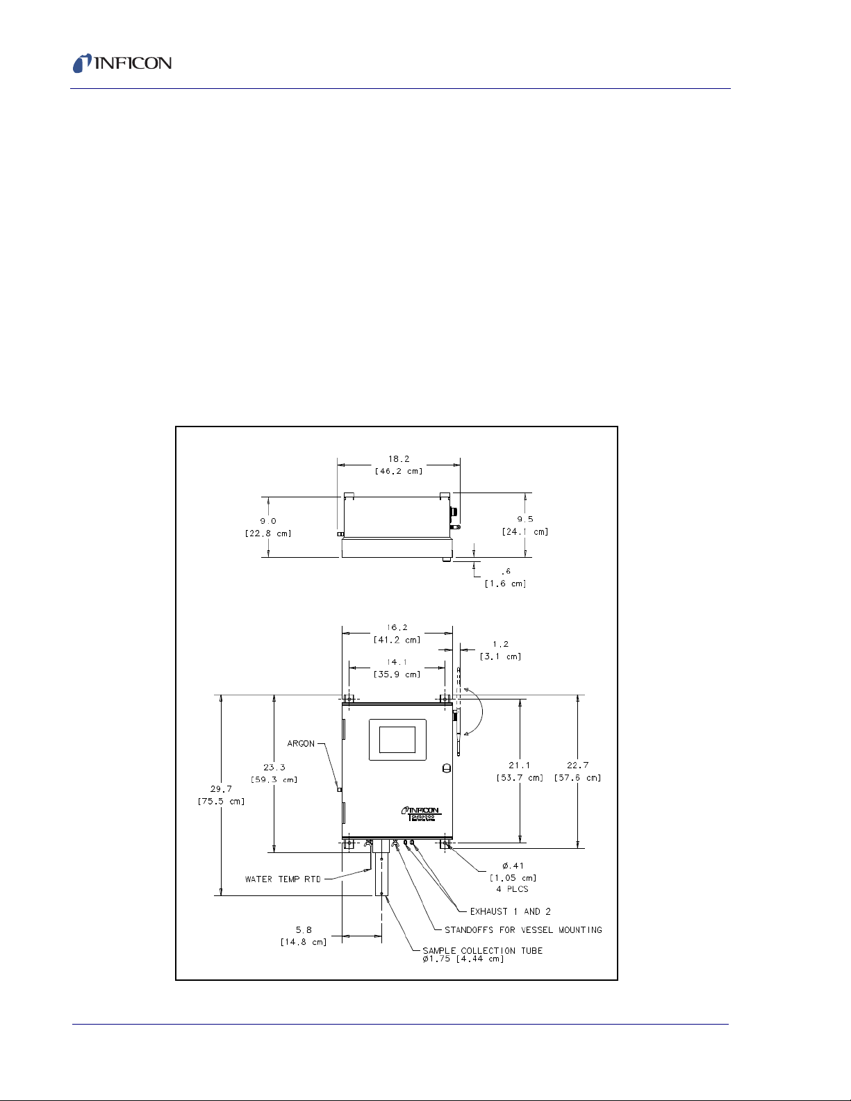
To ensure proper operation when utilizing the CMS5000 for continuous water
monitoring, it is necessary to determine optimal mounting height and unit
placement to accommodate both the water intake as well as allow for clearance for
the sample collection tube when attaching and removing the sampling vessel.
Allow a minimum of a 15” (38.1 cm) clearance below the mounted sampling vessel
for vessel removal. Verify that the CMS5000 is level when mounted and that the
slope is less than five percent. See Figure 3-2.
Figure 3-2 Dimensions for Mounting the CMS5000
3 - 4
IPN 074-508-P1C
Page 25
CMS5000 Operating Manual
3.5 Water Monitoring Assembly Instructions
If not using the CMS5000 for water monitoring, skip to section 3.8 on page 3-8.
The temperature sensor, or RTD, will be unfastened and taped to the bottom of the
CMS5000 for shipment. Remove the tape, guide the excess wire back into the
CMS5000, and screw the stainless steel nut into the port nearest to the beige
sample collection tube mounting bracket located on the bottom of the CMS5000.
The Swagelok® fitting should be tightened 1/4 turn past finger tight using a 7/16”
open end wrench. See Figure 3-3.
Figure 3-3 Attaching the Temperature Sensor
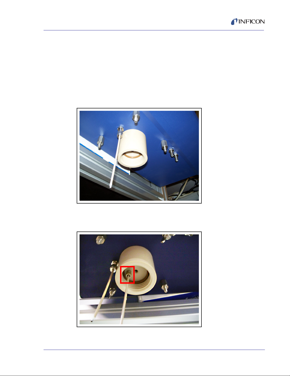
The PEEK purge tube (found in the ship kit) is attached to the middle port in the
beige sample collection tube mounting bracket. See Figure 3-4.
Figure 3-4 Attaching the PEEK Purge Tube
IPN 074-508-P1C
3 - 5
Page 26
CMS5000 Operating Manual
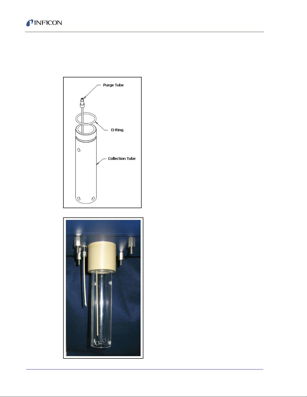
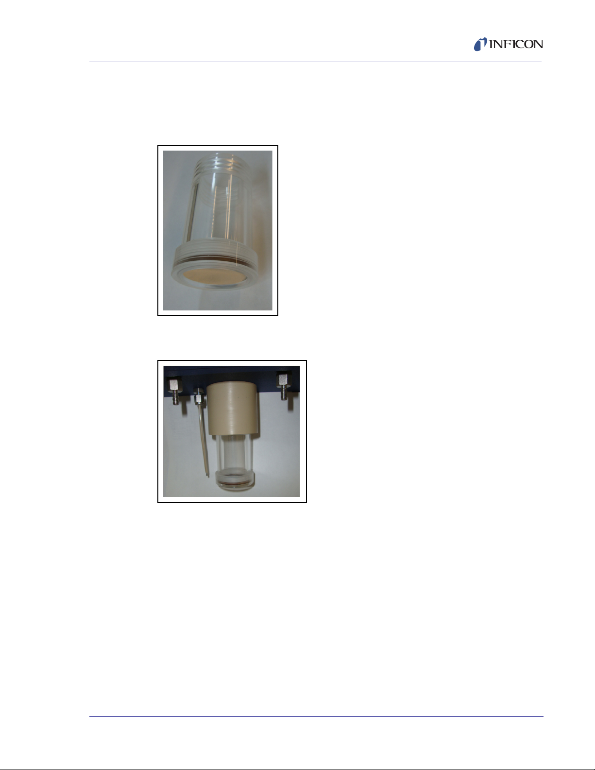
Install the collection tube o-ring into the beige sample collection tube mounting
bracket. Screw the clear acrylic sample collection tube from the ship kit into the
beige sample collection tube mounting bracket located on the bottom of the
CMS5000 until finger tight. Do not over tighten. See Figure 3-5 and Figure 3-6.
Figure 3-5 Attaching the sample collection tube
Figure 3-6 Attached Sample Tube
IPN 074-508-P1C
3 - 6
Page 27
CMS5000 Operating Manual
3.6 Attaching the Water Sampling Vessel
NOTE: If you are not using the CMS5000 for water monitoring, skip sections
section 3.6 and section 3.7.
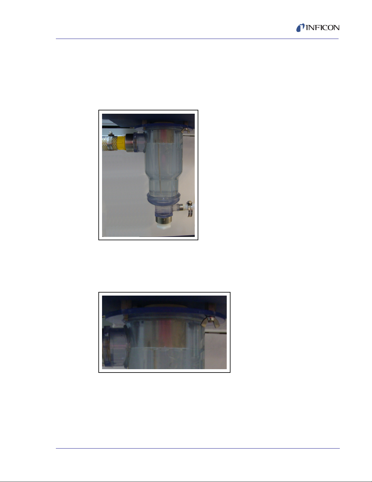
The optional sampling vessel mounts to the bottom of the CMS5000 using the wing
nuts supplied in the sampling source kit. See Figure 3-7.
Figure 3-7 Optional Sampling Vessel
Attach the sampling vessel to the CMS5000 by aligning the screws with the four
openings on the flange of the sampling vessel. Hold the vessel against the
mounting screw standoffs and screw on the wing nuts to hold the sampling vessel
in place. See Figure 3-8.
Figure 3-8 Attaching the Sampling Vessel
IPN 074-508-P1C
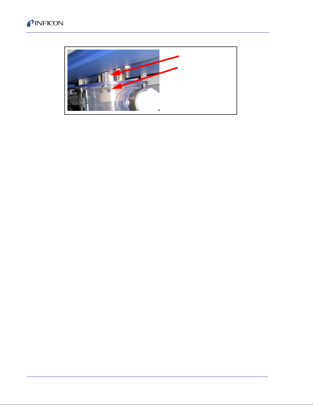
The function of the standoffs is to provide spacing between the CMS5000 and the
vessel to allow water overflow to prevent water from entering the analytical module.
See Figure 3-9.
3 - 7
Page 28
CMS5000 Operating Manual
Standoffs
Wingnuts
Figure 3-9 Standoffs for Overflow
3.7 Connecting the Water Supply
If not using the CMS5000 for water monitoring, skip this section.
It is the responsibility of the integrator to configure any and all plumbing. Care
should be taken to support the weight of all plumbing hoses and hardware
independently of the CMS5000.
3.8 Air Monitoring Assembly Instructions
The CMS5000 easily converts to a continuous Air Monitoring System via two
configurations. The first configuration, designed for ambient air sampling, requires
the user to replace the water collection tube with a air collection tube with attached
filter. The filter at the opening of the collection tube prevents large particulates in
the sampling environment from entering the system.The second configuration is
designed for in-line air sampling. This configuration is more complex.
IPN 074-508-P1C
3 - 8
Page 29
3.8.1 Ambient Air Sampling
Ambient air sampling requires only the Air Sampling Tube (Figure 3-10). See
Figure 3-10.
Figure 3-10 CMS5000 Air Sampling Tube
Attach the Air Sampling Tube. See Figure 3-11.
CMS5000 Operating Manual
Figure 3-11 CMS5000 with Air Sampling Tube Attached
IPN 074-508-P1C
3 - 9
Page 30
CMS5000 Operating Manual
Center Port
Air Monitoring
Sample Inlet Line
Configuration
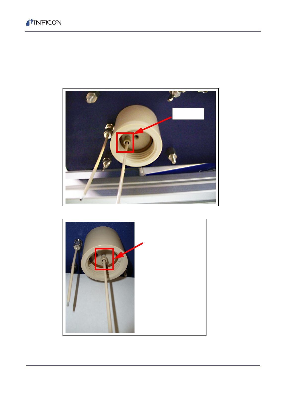
3.8.2 Air Line Sampling
Preparing the CMS5000 is more intensive for this type of sampling. First, attach a
sampling inlet line with a 1/8" compression fitting (with ferrule). In the example, the
purge line is removed from the center port (Figure 3-12) and moved to the right port
to become the Sample Inlet Line (Figure 3-13).
Figure 3-12 Purge Line in Position for Water Sampling
Figure 3-13 Sample Inlet Line in Postition for Air Sampling
IPN 074-508-P1C
3 - 10
Page 31

CMS5000 Operating Manual
CAUTION
Sample
Compression
Fitting
Sample Inlet
Exhaust Line
Detector
Exhaust
If switching from air line sampling to water sampling,
carefully move the purge tube back to the proper inlet.
Placing the sample inlet line in the wrong port will allow
water to be drawn into the CMS5000 and will cause
severe damage to the unit.
The pressure of the sample in the air line must be greater than exhaust of the
CMS5000 but no more than 1 atm. This will prevent any back pressure from
re-entering the sample path and collecting more sample than necessary onto the
concentrator. Sample flow is directional, and when the pressure changes the flow
also changes. The exhaust line is attached to the exhaust port via a compression
fitting (see Figure 3-14). The exhaust line should have at least the same internal
diameter as the sample inlet.
Figure 3-14 Exhaust Line Attached
IPN 074-508-P1C
An example of air line sampling setup is shown in Figure 3-15.
Figure 3-15 Example Air Line Sampling Setup
3 - 11
Page 32

CMS5000 Operating Manual
3.9 Connecting the Argon Supply
It is the responsibility of the user to provide the argon supply. An ultra high purity
source of argon (99.99999%) is required for optimal operation of the MAID. The
included regulator is preset at the factory to the required pressure (90 psi). Connect
the argon supply to the CMS5000 using the included Teflon argon supply line and
the quick connect valve. The fitting for the quick connect is located on the left side
of the mounted analytical module. See Figure 3-16.
Figure 3-16 Connecting the Argon Supply to the CMS5000
3 - 12
IPN 074-508-P1C
Page 33

3.10 Connecting the Power Supply
Power Supply
Connect the 4 pin Fischer Connector® from the power supply to the 4 pin
receptacle near the rear of the upper right side of the CMS5000. Connect the plug
end of the power supply to electrical outlet. The CMS5000 will power on
automatically. The CMS5000 does not have an “on” switch. See Figure 3-17.
Figure 3-17 Connecting the Power Supply
CMS5000 Operating Manual
NOTE: The CMS5000 contains an onboard permeation tube for internal
calibration. The permeation tube is designed to continually emit toluene at
a particular rate. During shipments, power outages, or prolonged periods
of time when the CMS5000 is powered off, the permeation tube will
continue to emit toluene, thus causing a buildup of toluene within the
CMS5000. This is normal and expected. To compensate for this buildup, it
is necessary to run the CMS5000 with an argon purge for a period of
approximately 24 hours to allow the permeation tube to equilibrate. The
permeation tube is considered to be equilibrated when a stable response
for toluene is observed from consecutive runs of the check standard
calibration method. See Chapter 5, Software Setup for information on
calibrating the check standard.
IPN 074-508-P1C
3 - 13
Page 34

CMS5000 Operating Manual
Ethernet
I/O
3.11 Communication Configuration
Select the desired communication configuration from the selections below.
3.11.1 Ethernet
The Ethernet port used to connect the CMS5000 to a PC or network is located on
the upper right side of the CMS5000, next to the wireless antenna. Plug the end of
the Ethernet cable with the water tight cap into the CMS5000 and plug the other
end into a PC or network. See Figure 3-18.
3.11.2 I/O
The multi-pin I/O cable receptacle is located on the right side of the CMS5000 next
to the power supply receptacle. Plug the multi-pin Fischer Connector from the I/O
cable into the CMS5000 and configure the other end of the cable as desired. See
Figure 3-18.
Figure 3-18 Connecting the Ethernet and I/O
3 - 14
IPN 074-508-P1C
Page 35

Setting Up Laptop Communication
4.1 Introduction
Communication must be established between the CMS5000 and the PC in order
to run analysis and review data from the laptop. It is necessary to use the laptop to
calibrate the CMS5000 methods and setup software parameters.
4.1.1 Setting Up Laptop Communications
NOTE: Setting up communication is an Advanced User function. To change the
access level, see section 11.2.5.1, Set Access Level, on page 11-18.
1 Open CMS IQ Software. From the System drop-down menu, select
Properties. See Figure 4-1.
Figure 4-1 Selecting Properties from the System Drop-down Menu
CMS5000 Operating Manual
Chapter 4
2 Click the CMS5000 List button. See Figure 4-2.
Figure 4-2 CMS5000 List Button
IPN 074-508-P1C
4 - 1
Page 36

CMS5000 Operating Manual
3 Enter the IP Address for the CMS5000 into the Enter New CMS5000 Name or
IP Address. (The IP Address can be found on the Front Panel of the CMS5000
by touching STAT Scroll down using the DOWN key to select NET.) See section
6.4, NET Option, on page 6-2. An example of an IP address is 10.210.50.116.
Click Add. See Figure 4-3.
Figure 4-3 Add CMS5000
4 The newly added CMS5000 will be displayed in the CMS5000 List.
Double-click OK.
Figure 4-4 Closing the CMS5000/TCP Window
IPN 074-508-P1C
4 - 2
Page 37

CMS5000 Operating Manual
5 Press OK on the System Properties Window.
Figure 4-5 Closing the System Properties Window
6 The newly added CMS5000 icon will now be displayed at the bottom of the
System Setup Screen. If the CMS5000 is displayed without an "X", as in Figure
4-6, communication has been established.
Figure 4-6 Newly Added CMS5000
6a If the CMS5000 is overlaid with a red "X", the CMS5000 is not properly
communicating with the Laptop. If the CMS5000 icon is overlaid with a blue "X",
communication has not been fully established. See Figure 4-8 and Figure 4-8.
Figure 4-7 CMS5000 Not Properly Communicating with the Laptop
IPN 074-508-P1C
Figure 4-8 Communication Has Not Been Established Between CMS5000 and Laptop
4 - 3
Page 38

CMS5000 Operating Manual
NOTE: If a communication error has occurred, which is indicated by an "X",
contact the system administrator or integrator. If not available, follow the
instructions in Configuring the CMS5000 for Laptop Communications, see
section 4.1.2.
4.1.2 Configuring the CMS5000 for Laptop Communications
1 Touch the STAT key on the front panel of the CMS5000 to display the STATUS
page. See Figure 4-9.
Figure 4-9 STATKey
2 Use the DOWN key to highlight NET and touch SEL. See Figure 4-10.
Figure 4-10 Accessing NET Screen
IPN 074-508-P1C
4 - 4
Page 39

CMS5000 Operating Manual
3 Each CMS5000 will have a unique IP address. An example of an IP address is
10.210.50.107. The subnet mask is also displayed on the NET page. An
example of a subnet mask is 255.252.0.0. See Figure 4-11.
Figure 4-11 NET Page
4 On the PC, click the Windows Explorer Start button. See Figure 4-12.
Figure 4-12 Start
4a Mouse over Settings and click Network Connections. See Figure 4-13.
Figure 4-13 Network Connections
IPN 074-508-P1C
4 - 5
Page 40

CMS5000 Operating Manual
5 Double-click on the desired connection. Choose Local Area Connection to
connect with an Ethernet cable. Choose Wireless Connection to connect
wirelessly.
Figure 4-14 Select Connection
6 The Connection Status window will open. Click Properties. See Figure 4-15.
Figure 4-15 Local Area Connection Status Window
4 - 6
IPN 074-508-P1C
Page 41

CMS5000 Operating Manual
7 In the General tab, scroll down and highlight Internet Protocol (TCP/IP), click
Properties. See Figure 4-16.
Figure 4-16 Selecting Internet Protocol (TCP/IP)
8 Select Use the following IP address. Enter the first number of the IP address
into the first slot. For example, if the IP address is 10.210.50.107, enter 10 into
the first slot. Refer to Step 2 on page 16-3 to find the IP address on the
CMS5000. See Figure 4-17.
Figure 4-17 Entering First Number of IP Address
IPN 074-508-P1C
4 - 7
Page 42

CMS5000 Operating Manual
9 For the second number of the IP address, enter 210 if connecting with the
cable, or 209 if connecting with the wireless radio, into the second slot. See
Figure 4-18.
Figure 4-18 Entering Second Number of IP Address
10 For the third number of the IP address, add 128 (the maximum total number is
255) to the number in the IP address. In this example, adding 128 to 50 equals
178, so 178 is entered into the third slot. See Figure 4-19.
NOTE: If the total third number is greater than 255, add 5 to the original third
number.
Figure 4-19 Entering Third Number of IP Address
IPN 074-508-P1C
4 - 8
Page 43

CMS5000 Operating Manual
11 The fourth number of the IP address is entered into the fourth slot without
modification. Therefore, in this example, 50 would be entered into the fourth
slot. See Figure 4-20.
Figure 4-20 Entering Fourth Number of IP Address
12 Press OK in the Internet Protocol Properties window to close. See Figure
4-21.
Figure 4-21 Closing the Internet Protocol Properties Window
IPN 074-508-P1C
4 - 9
Page 44

CMS5000 Operating Manual
13 Communication between the CMS5000 and the Laptop is now established as
indicated by the absence of an "X" over the CMS5000 Sensor in the System
Setup Screen. See Figure 4-22.
Figure 4-22 Active CMS5000 Sensor Icon
4 - 10
IPN 074-508-P1C
Page 45

5.1 Software Setup
Prior to running continuous analyses, CMS5000 methods require calibration. This
chapter provides instructions for calibrating the Check Standard method, the Water
Purge method, and the Air Purge method.
Various software parameters will need to be established in order to operate the
CMS5000 and retrieve data. This includes entering startup and input methods,
setting up the FTP server(s) and if desired, sequencing methods.
5.2 Calibrating the Check Standard
1 Run the check standard method, CMS5000 Ck Std. See Chapter 7, Operation
for information on running a method.
CMS5000 Operating Manual
Chapter 5
Software Setup
NOTE: The onboard toluene permeation tube is considered to be equilibrated
when a stable response for toluene is observed. Consecutive runs of
the check standard method may need to be run until the toluene
response is stable.
2 The finished run will look similar to the chromatogram shown in Figure 5-1.
Figure 5-1 Check Standard Method Run
IPN 074-508-P1C
3 When the method has finished running, open CMS IQ on the PC.
Figure 5-2 CMS IQ
5 - 1
Page 46

CMS5000 Operating Manual
4 Click on the Calibrate button on the top toolbar. See Figure 5-3.
Figure 5-3 Calibrate Button
5 Double-click to select the desired method. See Figure 5-4.
Figure 5-4 Selecting Method for Calibration
6 A screen similar to Figure 5-5 will be displayed.
Figure 5-5 Calibrate Screen
IPN 074-508-P1C
5 - 2
Page 47

CMS5000 Operating Manual
NOTE: To change the selected method, use the top Browse button in the
Method section on the left hand side of the screen. See Figure 5-6.
Figure 5-6 Browse Button
7 Click the Browse button in the Data Files section to enter a data file. See
Figure 5-7.
Figure 5-7 Data File Browse Button
IPN 074-508-P1C
5 - 3
Page 48

CMS5000 Operating Manual
8 Select the data file generated from the method run in step 1. To locate the file,
first select the data folder for the method. Then, select the individual data file.
See Figure 5-8 and Figure 5-9.
Figure 5-8 Method Data Folder
Figure 5-9 Individual Data File
IPN 074-508-P1C
5 - 4
Page 49

CMS5000 Operating Manual
9 Verify that toluene is the only component in the library. See Figure 5-10.
Figure 5-10 Is Check Std Library Box
NOTE: If the Methods Differ message is displayed, verify that the differing
parameters are acceptable and click Yes. If the parameters are not
acceptable, run a calibration sample with the exact method selected in
the Method box and use that data file. See Figure 5-11.
Figure 5-11 Methods Differ Message
IPN 074-508-P1C
inconsistent. This message is displayed because units for the data files have
yet to be selected. Click OK to continue. See Figure 5-12.
Figure 5-12 Inconsistent Data Files
5 - 5
10 A message will be displayed stating that the units between the data files are
Page 50

CMS5000 Operating Manual
11 The data file will be loaded into the Data Files list. See Figure 5-13.
NOTE: Only one file should be loaded into this list.
Figure 5-13 Data File List
12 Check the Reset Library box. Checking this box will reset the calibration curve
by deleting all points currently contained in the library. See Figure 5-14.
Figure 5-14 Reset Library
IPN 074-508-P1C
5 - 6
Page 51

CMS5000 Operating Manual
13 In the Conc/Factor column, set the concentration to 1. See Figure 5-15.
Figure 5-15 Conc/Factor Column
14 Check the Selection box to process this data file. See Figure 5-16.
Figure 5-16 Selection Box
IPN 074-508-P1C
5 - 7
Page 52

CMS5000 Operating Manual
15 Underneath Peak Search, verify that Search is selected. Click on Start to run
the calibration. See Figure 5-17.
Figure 5-17 Running Calibration
16 Click on the Analytes in File tab to view the area counts for the data file.
Ensure that an area count is displayed for the analyte. Then, save the method
by clicking Save. See Figure 5-18.
Figure 5-18 Analytes in File Tab
17 The check standard calibration is now complete.
IPN 074-508-P1C
5 - 8
Page 53

CMS5000 Operating Manual
5.3 Calibrating the Water or Air Purge Methods
1 Both CMS5000 Water Purge and Air Purge methods requires calibration at
initial startup. Susbsequent calibrations may be performed as necessary.
NOTE: In the CMS5000 Water Purge method, the actual water temperature is
recorded during calibration-the CMS IQ software uses the Beta Value
to automatically compensate for the water sample temperature
fluctuations.
2 Refer to section 16.2, Using the Calibrate Function, and follow steps 1-11 to
prepare and run standards for the calibration.
NOTE: The water temperature of the calibration standards needs to be
uniform when creating water calibration methods.
3 Verify that the retention times of the analytes in the standard with the highest
concentration correspond to the retention times in the library template
associated with the method.
3a To select a peak, follow the instructions in section 12.8, How to Access the
Scan Cursor, on page 12-25. See Figure 5-19.
Figure 5-19 Selecting a Peak
4 The actual retention times should be within +/- 0.5 seconds of the library
retention times
5 Refer to section 16.2, Using the Calibrate Function, and follow steps 22-23.
IPN 074-508-P1C
6 Refer to section 16.2, Using the Calibrate Function, and follow steps 27-37.
7 Perform an initial calibration verification of the CMS5000 Water Purge method
by running the calibration standard at a concentration within the limits of the
calibration curve. See Chapter 7, Operation, for information on running a
method.
8 Refer to section 16.3.6, View Reports, to access the report of the calibration
verification standard. Verify that the reported concentration is within 30% of the
actual concentration.
5 - 9
Page 54

CMS5000 Operating Manual
5.4 FTP Connection
Up to three FTP servers, each with its own unique IP address, user name and
password, can be configured to upload data files and can be enabled or disabled
independently. If a FTP server is enabled, the CMS5000 will maintain a queue on
which to upload data files. After each run, the CMS5000 will upload the files onto
the queues. If the CMS5000 cannot connect or login to an FTP server, the data file
will be stored in the queue until another data file is ready to be uploaded. At this
point, the CMS5000 will attempt to upload both the new and the previous data file.
If there is a loss of power, the data files will continue to be stored in the queues.
However, if a data file is deleted by a user prior to uploading, the CMS5000 will not
transfer the file to the FTP server. The CMS5000 also has an option to clear the
files in the queue if the data is no longer desired.
1 Verify that the PC will connect to the FTP server. If the PC can connect to both
the FTP server and the CMS5000, it can be configured to upload data files.
2 To verify the connection, first open Internet Explorer. See Figure 5-20.
Figure 5-20 FTP Server
5 - 10
IPN 074-508-P1C
Page 55

CMS5000 Operating Manual
3 Type in the FTP address of the server using the following format: "ftp://<ip
address>". See Figure 5-21.
Figure 5-21 FTP Server
4 Enter the Username and Password of the ftp server. Click Log On. See Figure
5-22.
Figure 5-22 Entering Username and Password
IPN 074-508-P1C
5 - 11
Page 56

CMS5000 Operating Manual
5 When the PC connects to the FTP site, the screen will look similar to the one
that is displayed in Figure 5-23. Once the connection has been verified, this
screen can be closed by clicking the "X" button.
Figure 5-23 FTP Site
6 Open CMS IQ which is located on the desktop. See Figure 5-24.
Figure 5-24 CMS IQ Icon
7 Click the Status icon. See Figure 5-25.
Figure 5-25 Status Icon
IPN 074-508-P1C
5 - 12
Page 57

CMS5000 Operating Manual
8 Click on the Data Settings tab. See Figure 5-26.
Figure 5-26 Data Settings Tab
9 Click on the Configure FTP Settings button. See Figure 5-27.
Figure 5-27 Configure FTP Settings
IPN 074-508-P1C
5 - 13
Page 58

CMS5000 Operating Manual
10 Enable the number of FTP servers to upload by checking the Enable FTP
boxes. Note that FTP1 is enabled as default. Up to three FTP servers can be
uploaded. See Figure 5-28.
Figure 5-28 FTP Config Window
5 - 14
IPN 074-508-P1C
Page 59

CMS5000 Operating Manual
11 Enter in the FTP server information including FTP Server IP address,
username, and password. Also enter the Connection Timeout (the amount of
time the CMS5000 will wait for a response from the FTP site), the Upload
Timeout (the allotted time for a single file to upload), and the # of Upload
Retries (the number of times the CMS5000 will attempt to communicate with
the FTP server if the Upload Timeout is reached).
NOTE: The State will be indicated as Standby mode . When the CMS5000 is
actively transmitting data to the FTP server, the State will indicate
Running. See Figure 5-29.
Figure 5-29 Entering FTP Server Information
IPN 074-508-P1C
5 - 15
Page 60

CMS5000 Operating Manual
12 Click on the Network Settings button. See Figure 5-30.
Figure 5-30 Network Settings
13 To locate the Network Gateway, click on the start button on the desktop. See
Figure 5-31.
Figure 5-31 Start Button
14 Select Run... from the menu. See Figure 5-32.
Figure 5-32 Run
IPN 074-508-P1C
5 - 16
Page 61

CMS5000 Operating Manual
15 The Run window will be displayed. See Figure 5-33.
Figure 5-33 Run Window
16 Type in cmd and click OK. See Figure 5-34.
Figure 5-34 CMD
17 At command prompts on the PC, enter route PRINT to verify the default
Network Gateway setting. See Figure 5-35.
Figure 5-35 route PRINT
18 The default gateway will be displayed. See Figure 5-36.
IPN 074-508-P1C
Figure 5-36 Default Gateway
5 - 17
Page 62

CMS5000 Operating Manual
19 Enter in the Network Gateway settings. See Figure 5-37 and Figure 5-38.
Figure 5-37 Network Gateway Settings
Figure 5-38 Entering Network Gateway Settings
20 The number at the bottom of the screen should match the Network Gateway
setting in CMS IQ. If not, re-enter the Network Gateway setting displayed on
the PC into CMS IQ. See Figure 5-39.
Figure 5-39 Matching Gateway Settings
5 - 18
IPN 074-508-P1C
21 Accept the Network Gateway settings by clicking OK. See Figure 5-40.
Figure 5-40 Accepting Network Gateway Settings
Page 63

CMS5000 Operating Manual
22 Accept the FTP Server settings by clicking OK. See Figure 5-41.
Figure 5-41 FTP Server Settings
23 Click OK to exit the Properties screen. See Figure 5-42.
Figure 5-42 Exiting the Properties Screen
IPN 074-508-P1C
24 FTP site is now setup and communicating.
5 - 19
Page 64

CMS5000 Operating Manual
5.5 System Integration
The current system I/O integration allows only input commands. This includes the
selection and start of a method created in the CMS IQ software. See section 5.6,
Setting Startup Methods, for details on how to input methods. For more advanced
integration details, please contact INFICON.
5.6 Setting Startup Methods
The CMS5000 can be operated automatically. In the Parameters tab, a Startup
Method, a method that will automatically run when powering on the system, can
be selected. Additionally, a method sequence can be selected as a startup method.
See section 5.8 on page 5-25 for information on creating a method sequence.
1 Double-click the Status icon, which is located on the System Setup screen of
CMS IQ. See Figure 5-43.
Figure 5-43 Status Icon
2 Click on the Parameters tab. See Figure 5-44.
Figure 5-44 Parameters Tab
IPN 074-508-P1C
5 - 20
Page 65

CMS5000 Operating Manual
3 Click on the Browse button for the startup method. See Figure 5-45.
Figure 5-45 Browse Button
4 Double-click on the desired method from the method folder or highlight the
method and click OK. See Figure 5-46.
Figure 5-46 Choosing Startup Method
IPN 074-508-P1C
5 - 21
Page 66

CMS5000 Operating Manual
5 The chosen method will be displayed. See Figure 5-47.
Figure 5-47 Startup Method
6 To clear the startup method, click on Clear Startup Method. See Figure 5-48.
Figure 5-48 Clear Startup Method
5 - 22
IPN 074-508-P1C
Page 67

5.7 Input Methods
In the Input/Output tab, up to four input methods can be selected. An input method
will begin when a relay contact, which has been integrated into the water/air control
system, triggers its start. Also, a method sequence can be selected as an input
method. See section 5.8 on page 5-25 for information on creating a method
sequence.
1 To enter input methods, click the appropriate Browse button. See Figure 5-49.
Figure 5-49 Input Browse Buttons
CMS5000 Operating Manual
2 Double-click on the desired method from the method folder. See Figure 5-50.
Figure 5-50 Choosing Input Method
IPN 074-508-P1C
5 - 23
Page 68

CMS5000 Operating Manual
3 The selected input method will appear in the Input 1 Method field. To clear the
input method, click the Browse button for the desired method.
See Figure 5-51.
Figure 5-51 Clearing Input Method
4 Click X without selecting a method. See Figure 5-52.
Figure 5-52 Clicking "X"
5 - 24
IPN 074-508-P1C
Page 69

5 The method will be cleared from the selected input method line.
See Figure 5-53.
Figure 5-53 Method Cleared
5.8 Method Sequence
CMS5000 Operating Manual
A series of methods can be selected to run at timed intervals, which includes
consecutive runs. Once the series has been started, it can run unattended and
unprompted until the sequence has finished. Follow the instructions below to
create a method sequence.
1 From the CMS IQ Setup screen, double-click the Method Editor icon.
See Figure 5-54.
Figure 5-54 Method Editor Icon
2 The Edit Method window will be displayed. Click on Method Sequence.
IPN 074-508-P1C
See Figure 5-55.
Figure 5-55 Edit Method Window
5 - 25
Page 70

CMS5000 Operating Manual
3 In the Method Name box, type in a name for the method sequence or use the
name provided. Verify that the file extension for the method name is .xmth.
See Figure 5-56.
Figure 5-56 Method Name Box
4 Click the Method Sequence (...) button. See 4.
Figure 5-57 Adding Method File
IPN 074-508-P1C
5 - 26
Page 71

CMS5000 Operating Manual
5 A list of methods will be displayed. Double-click the desired method for
sequencing. See Figure 5-58.
Figure 5-58 Selecting Method to Sequence
6 The selected method will be displayed in the method sequence list. See Figure
5-59.
Figure 5-59 Selected Method
IPN 074-508-P1C
5 - 27
Page 72

CMS5000 Operating Manual
7 In the Start Run column, choose either Run Button or Immediately for each
method. This selection determines how each method in the run is started. See
Figure 5-60.
NOTE: If the Run Button option is selected, the run button will have to be
pressed each time. If Immediately is selected, the method will
automatically commence.
Figure 5-60 Start Column Selection
8 In the End Run column, choose Sleep for or Sleep until for each method. See
Figure 5-61.
NOTE: The Sleep for option is used to enter a time period, such as one hour.
The Sleep until option is for a specific time, such as one o’clock.
Figure 5-61 Sleep Column
IPN 074-508-P1C
5 - 28
Page 73

CMS5000 Operating Manual
9 In the End Run column, enter the desired time for the next method to start or
the length of time to sleep before the next method starts. See Figure 5-62.
NOTE: Enter 0:00:00 to run the next method as soon as the previous one has
finished.
Figure 5-62 Time Column
10 Repeat steps 4-9 to add additional methods for sequencing. Alternately,
right-click anywhere in the windowand select Duplicate Row. See Figure 5-63.
Figure 5-63 Duplicate Row
IPN 074-508-P1C
11 When the desired sequence has been entered, the user can either enter a
number up to repeat the sequence a set number of times (Number of
Iterations, see Figure 5-64), or run a continuous loop of the sequence without
stopping (Run Continuously, see Figure 5-65).
5 - 29
Page 74

CMS5000 Operating Manual
NOTE: When using Run Continuously, the Number of Iterations option is
grayed out. See Figure 5-65.
Figure 5-64 Number of Iterations
Figure 5-65 Run Continuously
IPN 074-508-P1C
5 - 30
Page 75

CMS5000 Operating Manual
12 Click Save when all the desired methods have been entered. See Figure 5-66.
Figure 5-66 Saving the Method Sequence
13 Save the method sequence to the desired location. Click OK. See Figure 5-67.
Figure 5-67 Save Method Sequence
IPN 074-508-P1C
5 - 31
Page 76

CMS5000 Operating Manual
This page is intentionally blank.
5 - 32
IPN 074-508-P1C
Page 77

6.1 Introduction
The STAT button provides real time data regarding various system parameters.
These parameters include the SYS (system) option, the TIME (time) option, the
NET (network) option, the STAT (status) option and the FIRM (firmware) option.
6.2 SYS Option
The first option, SYS, provides system information including the Hostname, Serial
Num (Number), Ver sion number, Built on (build date), Free Disk space, and the
Startup method. The Hostname is used for PC communication, and the Serial
Num is the serial number of the unit that is used for identification. Version displays
the version of CMS5000 software that is loaded onto the system. The date and time
that the software was released is located in the Built on field. Free Disk is the
amount of free disk space available for data storage and the last entry is the
Startup which is the method that will automatically run when turning on the unit.
See Figure 6-1. Navigate through the SYS options by using the UP and DOWN
buttons.
CMS5000 Operating Manual
Chapter 6
Status Button
Figure 6-1 SYS Option
IPN 074-508-P1C
6 - 1
Page 78

CMS5000 Operating Manual
IP Address
Subnet Mask
6.3 TIME Option
The TIME option gives Date, Time (in a 24 hour format) and Time Zone
information. This option is used to timestamp the data files. See Figure 5-2. If the
time is incorrect, see section 9.3, Set Date, Time and Time Zone, on page 9-3 for
instructions.
Figure 6-2 TIME Option
6.4 NET Option
The NET option displays the IP Address, Subnet Mask, and the User Host. The
IP address and subnet mask can be used to set up communication between a
CMS5000 and a PC. This communication will allow for data to be transferred from
the CMS5000 to the PC for analysis and storage. The User Host is the laptop that
is communicating with CMS5000. See Figure 6-3.
Figure 6-3 NET Option
IPN 074-508-P1C
6 - 2
Page 79

6.5 STAT Option
The STAT option displays temperature information and carrier gas pressure. This
includes the current temperatures and the setpoint temperatures of the Regulator
Heater, Check Standard, Valve Oven, Column, Detector (MAID), and the Argon
Supply pressure. The state of the heaters will be shown, as well, with ctrl
indicating that the heaters are within 2 degrees of their setpoint. The temperature
of the water sample and the temperature of the card cage, which holds the boards
of the unit, are located beneath the temperatures of the heated components. The
pressure of the argon carrier gas is the last listing on the screen. See Figure 6-4.
NOTE: If the argon pressure is 380 kPa or less, a low-pressure warning will
Figure 6-4 STAT Option
CMS5000 Operating Manual
appear. When the pressure drops to 350 kPa, a low pressure error
message will be displayed.
6.6 FIRM Option
The FIRM option displays the firmware version for the gas chromatograph (GC)
and the front panel (FP). See Figure 6-5.
IPN 074-508-P1C
Figure 6-5 FIRM Option
6 - 3
Page 80

CMS5000 Operating Manual
This page is intentionally blank.
6 - 4
IPN 074-508-P1C
Page 81

7.1 Introduction
The CMS5000 can be programmed to operate uninterrupted or at timed intervals,
either through remote operation or through the front panel. Following a method run,
analysis results can be uploaded onto an FTP site allowing for data review at an
off-site location. The results are also stored directly onto the hard drive of the
CMS5000 unit.
The CMS5000 will commence sampling the air sample or the headspace above the
water sample at the beginning of the method run. The results will be shown on the
front panel during the run. If accessing data from a remote location, the results will
be available immediately following the method run.
7.2 Default Methods
Default methods are included with the CMS5000. The CMS5000 Ck Std method
verifies that the retention time and the response of the internal calibration standard
is within range. The CMS5000 Water Purge method detects specifically selected
VOCs during water monitoring. The CMS5000 Air Purge method detects
specifically selected VOCs during air monitoring.
CMS5000 Operating Manual
Chapter 7
Operation
7.3 System Calibration Standard
A toluene filled permeation tube is used to calibrate the CMS5000 system and has
a life span of approximately eight years. The software will use this calibration to
automatically compensate for normal fluctuations in detector sensitivity.
7.4 Operating the CMS5000 using the Front Panel
1 Touch ESC until the CMS5000 Main Menu is displayed. See Figure 7-1.
Figure 7-1 Main Menu
IPN 074-508-P1C
7 - 1
Page 82

CMS5000 Operating Manual
2 Run Method will be highlighted. Touch SEL. See Figure 7-2.
Figure 7-2 Selecting Run Method
3 Using the UP and DOWN keys, highlight the desired method. Touch SEL.
See Figure 7-3.
NOTE: Recent Methods will display the las methods run.
Figure 7-3 Highlighting Method
IPN 074-508-P1C
7 - 2
Page 83

CMS5000 Operating Manual
4 The system will begin heating in preparation for the method selected.
See Figure 7-4.
Figure 7-4 Heaters
5 Once the system is ready, a prompt to Press RUN to start method will be
displayed. Touch RUN. See Figure 7-5.
Figure 7-5 Press RUN to Start Method
IPN 074-508-P1C
7 - 3
Page 84

CMS5000 Operating Manual
6 While sample is being collected, the screen will display a Start Scanning in
message. See Figure 7-6.
Figure 7-6 Start Scanning Message
7 A chromatogram will be displayed while the method is running. Figure 7-7
depicts a finished chromatogram.
Figure 7-7 Finished Chromatogram
7 - 4
IPN 074-508-P1C
Page 85

CMS5000 Operating Manual
8 To re-run the same method through the front panel, touch RUN. See Figure 7-8.
Figure 7-8 Run Button
9 To return to the Main Menu, touch ESC. See Figure 7-9.
Figure 7-9 Returning to Main Menu
10 To see the results of the run, touch SEL. See Figure 7-10.
Figure 7-10 Run Results
IPN 074-508-P1C
11 For information on reading reports, see Chapter 8, Review Data.
7 - 5
Page 86

CMS5000 Operating Manual
This page is intentionally blank.
7 - 6
IPN 074-508-P1C
Page 87

8.1 Review Data
This option recalls data files for review. To access data files, follow the instructions
below.
1 Return to the Main Menu by pressing ESC. See Figure 8-1.
Figure 8-1 Main Menu
CMS5000 Operating Manual
Chapter 8
Review Data
2 Using the DOWN button, scroll to the second option Review Data and touch
SEL. See Figure 8-2.
Figure 8-2 Review Data
IPN 074-508-P1C
8 - 1
Page 88

CMS5000 Operating Manual
2a Alternately, touch 2 followed by SEL. See Figure 8-3.
Figure 8-3 Review Data
3 The data will be arranged in folders by method name. Select the desired folder
by scrolling through the list using the UP and DOWN buttons. Then, touch SEL.
See Figure 8-4.
Figure 8-4 Method Folders
8 - 2
IPN 074-508-P1C
Page 89

CMS5000 Operating Manual
4 Highlight the desired data file by using the UP and DOWN buttons. Then, touch
SEL. See Figure 8-5
NOTE: Files are named in the following format: method name_yearmonthday_
number of run for that date. Files will be in reverse chronological order with
the last data file at the top of the list. .
Figure 8-5 Selecting Data File
5 The desired file will be displayed. See Figure 8-6.
Figure 8-6 Recalled Data File
IPN 074-508-P1C
8 - 3
Page 90

CMS5000 Operating Manual
6 Press SEL to retrieve results in a report format.
7 The Summary report will be displayed. This report contains the information
about the method: the CAS number, the target (compound) name, the
predicted retention time, the actual retention time and the water temperature (if
running a water method). It also includes the date and time that the method was
run. Use the UP and DOWN buttons to view the full report. See Figure 8-7.
Figure 8-7 Summary Report
8 To access the Quant (Quantitative) Report, touch 2 followed by SEL. This
report contains the predicted retention time, the actual retention time, the area
and the concentration. Use the UP and DOWN buttons to view the full report.
See Figure 8-8.
Figure 8-8 Quantitative Report
9 Press ESC to return to the previous screen.
IPN 074-508-P1C
8 - 4
Page 91

9.1 Introduction
System is the third option on the Main Menu. This option will sets the date and time,
network addresses and language settings.
9.2 System Option
To select the System option, follow the instructions below.
1 Touch ESC until the Main Menu is displayed. See Figure 9-1.
Figure 9-1 Main Menu
CMS5000 Operating Manual
Chapter 9
System Option
2 Using the DOWN button, scroll until System is highlighted. See Figure 9-2.
Figure 9-2 System
IPN 074-508-P1C
9 - 1
Page 92

CMS5000 Operating Manual
3 Touch SEL. See Figure 9-3.
Figure 9-3 SEL Button
4 Alternately, touch 3 followed by SEL. See Figure 9-4.
Figure 9-4 Using the Number Keys to Select System
9 - 2
IPN 074-508-P1C
Page 93

9.3 Set Date, Time and Time Zone
The first option is to set the date and time. The CMS5000 will use this setting to
timestamp the files.
1 Scroll to Set Date and Time. Touch SEL. See Figure 9-5.
Figure 9-5 Set Date and Time
CMS5000 Operating Manual
2 The Current Date and Time screen will be displayed. To change the date,
touch SEL when the Date is highlighted. See Figure 9-6.
Figure 9-6 Set Time
IPN 074-508-P1C
9 - 3
Page 94

CMS5000 Operating Manual
3 Use the number keys to enter the date. Use the STOP button to enter a
forward slash. See Figure 9-7.
Figure 9-7 Date and Time
4 To save the date, touch SEL. See Figure 9-8.
Figure 9-8 Saving the Date
9 - 4
5 Upon saving, the system will return to the Current Date and Time screen.
IPN 074-508-P1C
Page 95

CMS5000 Operating Manual
6 To change the time, scroll to the Time option using the DOWN button.
See Figure 9-9.
Figure 9-9 Time Option
7 Enter the time using the number keys. To enter a colon, touch STOP.
See Figure 9-10.
Figure 9-10 Set Time
IPN 074-508-P1C
9 - 5
Page 96

CMS5000 Operating Manual
8 To save, touch SEL. See Figure 9-11.
Figure 9-11 Saving the Time
9 Upon saving, the system will return to the System screen. See Figure 9-12.
Figure 9-12 System Screen
9 - 6
IPN 074-508-P1C
Page 97

9.3.1 Set Network Info
The Set Network Info option allows the IP address to be changed on the
CMS5000.
1 Using the DOWN button, scroll to Set Network Info. See Figure 9-13.
Figure 9-13 Set Network Info
CMS5000 Operating Manual
2 Touch SEL. See Figure 9-14.
Figure 9-14
IPN 074-508-P1C
9 - 7
Page 98

CMS5000 Operating Manual
3 The IP address of the system will be displayed on the Network Addresses
page.
4 If an additional or different IP address is desired, scroll to Add IP Address
using the DOWN button. Touch SEL. See Figure 9-15.
Figure 9-15 Add IP Address Option
5 Using the number keys, enter in the new IP address. Use the STOP button to
enter in periods. See Figure 9-16.
Figure 9-16 Enter IP Address
IPN 074-508-P1C
9 - 8
Page 99

CMS5000 Operating Manual
6 To save, touch SEL. See Figure 9-17.
Figure 9-17 Enter IP Address
7 The system will return to the Network Addresses screen. See Figure 9-18.
Figure 9-18 Network Addresses
IPN 074-508-P1C
9 - 9
Page 100

CMS5000 Operating Manual
9.3.2 Set Language
The Set Language option is used to change the choice of language on the front
panel.
1 Using the DOWN button, scroll to Set Language. See Figure 9-19.
Figure 9-19 Set Language
2 The Set Language screen will appear. See Figure 9-20.
Figure 9-20 Set Language
IPN 074-508-P1C
9 - 10
 Loading...