

Page 1

INSTALLATION
AND OPERATING
AIRTHERM
Air Source Heat Pump
4.5, 9, 12
For users guide see reverse of book
When replacing any part on this appliance, use only spare parts that you can be
assured conform to the safety and performance specification that we require.
Do not use reconditioned or copy parts that have not been clearly authorised by Ideal.
For the very latest copy of literature for specification and maintenance practices visit our
website www.idealheating.com where you can download the relevant information in PDF format.
June 2011 UIN 204855 A03
SD535752 Issue 5
Page 2

2
Ideal airtherm - Air Source Heat Pump - Installation
Page 3

3Ideal airtherm - Air Source Heat Pump - Installation
Ideal airtherm 4.5, 9 & 12
Air Source Heat Pump
Destination Country: GB, IE
CONTENTS
How the Heat Pump Works ........................................... 4
Introduction .................................................................... 5
Heating with a heat pump ............................................. 5
Safety precautions ........................................................ 5
Location .......................................................................... 6
Unpacking ...................................................................... 6
Plumbing - pipework ..................................................... 7
Plumbing - buffer tank and hot water cylinder ........... 7
Electrical......................................................................... 8
Electrical Connections .................................................. 8
Internal wiring ................................................................ 8
Electrical Diagrams .................................................. 9-10
Internal Machine Circuit Diagrams ....................... 11-12
Frost protection ........................................................... 13
Control Panel ............................................................... 13
Commissioning ............................................................ 14
Handing Over ............................................................... 14
Fault nding ............................................................ 15-16
Data sheet .................................................................... 17
Machine dimensions, access panels and
electrical/water connections ................................. 18-20
System designs - S Plan ........................................ 21-22
System designs - W Plan ....................................... 23-24
System designs - Bivalent installation ...................... 25
Refrigeration Diagrams .......................................... 26-27
Optional weather compensation ................................ 28
Mounting the sensor ................................................... 29
Wiring of the Optional Weather Compensator .......... 29
Heat Pump and Buffer Installation Req ................ 30-33
Commissioning Checklist...................................... 34-35
Page 4

4
Ideal airtherm - Air Source Heat Pump - Installation
DOMESTIC
PREMISES
OUTSIDE
AIR
The EVAPORATOR collects heat from the
outside ambient air, pre-heated by the sun.
With Ideal, heat pumps high volumes of
outside air are drawn into the unit by the fan
and expelled through the evaporator fins.
The evaporator has liquid refrigerant
passing through it, which is at a
considerably lower temperature than the
ambient air, therefore the air gives up its
heat to the refrigerant, which then vaporizes.
This pre-heated vapour now travels to-
The COMPRESSOR where it is
compressed and upgraded to a
much higher temperature. The hot
vapour now enters-
The EXPANSION DEVICE and from
there, now at low pressure, it is
returned to the evaporator and the
cycle starts again.
The CONDENSER where it is surrounded
by water from the heating system. The heat
is given up to the cooler water and the now
cooler refrigerant returns to its former liquid
state but still under high pressure from the
compressor. This pressure is released by
passing the liquid through -
Coefficient of Performance
The efficiency of a Heat Pump is usually called its 'Coefficient of Performance' - (C.O.P.) which is simply a ratio of
heat output to energy input, both being expressed in kW. Thus a Heat Pump absorbing 1 kW of electricity, collecting
4 kW of energy from the air, and delivering 5 kW of heat to the pool water is said to have a C.O.P. of 5:1.
Naturally this ratio will vary according to the temperature of the water and the ambient air.
HOW THE HEAT PUMP WORKS
The Ideal airtherm Heat Pump provides thermodynamic heating by means of a vapour compression cycle
(similar to that employed in a conventional refrigerator), in addition to operating as an active solar collector.
Page 5

5Ideal airtherm - Air Source Heat Pump - Installation
GENERAL
INTRODUCTION
This installation manual is accompanied by a user guide (see
reverse of this book), a commissioning record sheet and a
warranty registration card, all of which should be left with the
householder. The user guide explains how the system works,
how it is controlled and what to do in the event of a problem. The
commissioning record sheet must be completed as its production
will be required in the event of a warranty claim.
HEATING WITH A HEAT PUMP
The Ideal heat pump is designed to operate up to 65oC water
temperature for the domestic hot water delivery, and negates
the need for direct electrical heating in the form of an electrical
emersion heater. The unit also provides space heating
temperatures variable from 35oC to 55oC.
Heat pumps for domestic heating are a fully proven technology
which will give many years of trouble-free service. Ideal Heat
Pumps which are MCS approved have been specically designed
for optimum operation in the UK’s climate.
However, unlike an oil or gas boiler which may be oversized for
the heating demand of the property and therefore regularly cycles
on and off, a heat pump is closely matched to the heat demand
and is designed to run for long periods without switching on/off.
The following steps must therefore always be taken to ensure a
successful installation. Major problems can occur if they are not
taken and failure to comply will invalidate the warranty.
a. SAP or equivalent heat loss calculations must be established
with the results recorded on the commissioning sheet.
b. The heat pump must be correctly sized in relation to the
calculated heat losses.
c. The space heating system must be capable of satisfying the
heat demand at the water ow temperature set for the heat
pump. This is particularly important where retro-tting a heat
pump to a radiator system designed originally for a Delta T of
60
o
C, as the heat pump will run at a Delta T of 30oC. In this
situation, you will normally need to t larger radiators.
d. The electrical supply must be adequate to meet the start
current demand.
e. The heat pump and the associated heating system must be
commissioned in accordance with the procedures laid down in
this manual.
A heat pump may be tted on a stand-alone basis (monovalent
system) to satisfy the full heating and hot water demand of the
property or in parallel with an existing boiler (bivalent system).
In the case of a bivalent installation the heat pump is sized to
provide a variable proportion of the annual heating requirement
(say 85%) with the existing boiler integrated to deliver the
balance on the coldest days. In bivalent systems, the heat pump
is sometimes only linked to the space heating system which
eliminates the requirement to t a new DHW cylinder.
Standard designs for several different congurations, including
plumbing and electrical circuits, are included in this manual.
REGULATIONS
The Ideal airtherm models conrm
• BSEN60335-1:2002&2-40:2003,andthereforecomply
withtheLowVoltageElectricalEquipmentDirective73/23/
EEC;93/68/EC.
• BSENISO12100-1:2003,BSENISO12100-2:2003,BS
ENISO13857:2008:BSENISO13850:2006,andtherefore
complywiththeSupplyofMachinery(Safety)Directive98/37/
EC.
• BSEN55014-1:2000+A1:2001+A2:2002,14-2:1997+A1:2001,
EN61000-3-2:2000,-3-3:1995+A1:2001,-4-2:1995,-43:1996,-4-4:1995,-4-5:1995,-4-6:1996,-4-11:1995.
andthereforecomplywiththeElectromagneticCompatibility
Directive2004/108/EC.
• ComplywiththePressureEquipmentDirective97/23/EC,
FluidGroup2,Category1.
• ComplianttoRoHSDirective2002/95/EC
SAFETY PRECAUTIONS
a. The unit must be securely installed on a structure that can
sustain its weight. If mounted on an unstable structure, it may
fall causing injury or damage.
b. If the heat pump is installed in an enclosed area, sufcient
ventilation must be provided so as not to impede the air ow
through the unit and to prevent the concentration of refrigerant
gas in the room building up in the event of a leak. (See
diagram - page 6)
c. All electrical work must be performed by a qualied technician
and comply with the latest I.E.E (17
th
) Regulations. The
machine should be installed in accordance with EMC
2004/108/EC.
d. Electricity to the unit must be supplied through dedicated
power lines and the correct voltage and circuit breakers must
be used. Power lines with insufcient capacity or incorrect
electrical work may result in electric shock or re. The
electrical ratings of Ideal heat pumps are included in the
datasheet on page 16 of this manual.
e. Any external heating device tted to the plumbing circuit of the
heat pump must have its own thermostatic control safety cut
out.
f. Immersion heater elements in any hot water tank must have a
built in thermostat.
Page 6

6
INSTALLATION
Ideal airtherm - Air Source Heat Pump - Installation
150mm
AIR INLET
AIR OUTLET
1500mm
500mm50mm
AT9630
TYPICAL INSIDE OR PLANT ROOM INSTALLATION
Grill or apertures MUST comply with Figures (See Table 1)
AIR FLOW
AIR FLOW
INCORRECT CORRECT
AT9631
Table 1
Model Minimum Free Area m
2
Inlet Discharge
airtherm 4.5 0.440 0.114
airtherm 9 0.440 0.114
airtherm 12 0.619 0.1313
LOCATION
The heat pump is suitable for outside installation.
a. Select a location where any potential noise disturbance is
minimised.
b. Provide a rm level base capable of supporting the weight
of the machine. Fixing holes are provided for bolting the
machine down to the base.
c. If wall mounting, ensure that the wall and framework are
capable of supporting the machine and use anti-vibration
mounts to prevent noise transmission. The weights of the
heat pumps are included on the data sheet on page 16 of
this manual.
d. If installing in a location exposed to strong wind, do not face
the air outlet of the unit against the direction of the wind as
wind entering the unit may impede the normal airow and
result in a malfunction.
e. Allow for the minimum clearances around the machine, as
shown below, required for unobstructed air ow and access
to service panels. A clearance of 1 metre above the unit is
recommended for servicing access through the top panel.
f. Consider protection from extreme weather conditions with a
cover or enclosure if the machine is installed externally
g. Consider tting a protective guard where the machine could
be exposed to vandalism or other damage.
h. If installed in a plant room or other building, ensure that the air
outlet is positioned directly adjacent to the outside wall with
inlet and discharge grilles or apertures of minimum free areas
as detailed below.
UNPACKING
AT9656
1. Position the heat pump close to point of installation on a
sound at surface and in an area large enough to unpack
the unit.
2. Carefully remove the plastic strapping securing the unit
and carton sleeve to the pallet.
3. Fold back the top aps to gain access to the literature
pack.
4. Remove the instructions and read thoroughly before
unpacking the product.
5. When ready for installation lift off the cardboard carton
sleeve.
6. Carefully remove the unit from the pallet.
Page 7

7
INSTALLATION
Ideal airtherm - Air Source Heat Pump - Installation
PLUMBING - PIPEWORK
a. Ideal heat pumps have water ow and return connections as
follows:
· The airtherm 4.5 and 9 models have ¾” BSP parallel,
male threads
· The airtherm 12 has 1” BSP, parallel, male threads
b. Couplings suitable for disconnection should be installed
with isolating valves on the ow and return of the heat pump
to ease installation and maintenance. During the initial
installation, these should be the last connections made so
as to avoid any stresses on the unit connections.
c. A drain valve or plug should be tted to the lower pipe to
facilitate drain down for servicing.
d. The condensate drain at the base of the unit collects the
condensation from the evaporator ns. This should be run
away to waste from the ¾” PVC pipe on the side of the heat
pump. The routing of the drain must be made to allow a
minimum fall of 1 in 20 away from the unit, throughout its
length.
e. Do not allow pipe work to run in front of service panels.
f. All pipe work must be adequately supported with allowance
for expansion/contraction and should be insulated to avoid
unnecessary heat loss.
a. The Ideal air source heat pump is normally designed to
operate with a buffer tank which prevents short cycling
during normal operation and provides a thermal store to aid
defrost of the heat pump. The size of the buffer tank needed
varies with the size of the ASHP unit as shown below.
Refer to Page 31-33 for addition information
b. Where the ASHP is required to supply domestic hot water, a
special DHW cylinder (Ideal cylinder) should be purchased
with each air to water heat pump. These cylinders have
a larger primary coil compared to standard cylinders and
are supplied with a special tank thermostat. An immersion
heater is tted for back-up DHW heating and must contain a
built in thermostat.
c. Where indirect pressurised cylinders are tted, they
should be installed in compliance with the relevant Water
Regulations and Building Regulations.
HEAT PUMP BUFFER TANK CAPACITY
airtherm 4.5 50 litres
airtherm 9 95 litres
airtherm 12 150 litres
PLUMBING - BUFFER TANK AND HOT WATER CYLINDERS
Page 8

8
INSTALLATION
Ideal airtherm - Air Source Heat Pump - Installation
a. A separately fused single phase supply is required. With all
power switched off, remove the electrics access panel to
gain access to the terminals in the electric box. The supply
cable, entering the unit through knock outs in the panel, can
then be fed through to connect into the live/neutral/earth
terminals.
b. An MCB type C or D or correctly rated fuse must be used.
(Refer to data sheet on page 17 of this manual).
c. A local isolator should be tted within 2 feet of the unit
to comply with I.E.E. regulations. Power to the unit is
indicated by the red indicator light on the console (mains
lamp).
d. A separate fused spur is normally used to supply the central
heating programmer and controls.
e. There are 10 connections to be made between the Ideal
heat pump and the control wiring centre. A multi core cable
with sufcient capacity will need to be provided and installed.
In most cases a 12 core 0.5mm control cable is used.
f. The unit may be live even when the mains lamp is off
ELECTRICAL
ELECTRICAL CONNECTIONS
a. The electrical connections diagrams are on pages 9 and 10
of this manual.
b. The wiring junction box is located behind the access panel
below the unit’s control panel
c. For the heat pump to operate, you must have a live signal
into terminal 9 (space heating) and terminal 1 (DHW).
INTERNAL WIRING
a. Internal wiring diagrams are on pages 11 and 12 of this
manual.
b. External wiring will depend on the heating system design
and is found on pages 22 & 24 of this manual.
due to live feeds from the external control system. The
‘programmer live’ light on the control panel conrms the
presence of a supply. (See diagram page 13).
g. The heat pump can operate in one of two modes, either set
as supplied, with the unit biased to hot water, or with no bias
for hot water or heating.
h. Ideal Boilers would always recommend a system with the
heating biased to hot water. However if room heating and
hot water heating are required at the same time, the link
between terminals 11 and 12 should then be tted. There is
then no bias between room heating and hot water heating.
Notes:-
i. Where the link is tted the unit will deliver 65ºC ow
temperature during periods of DHW demand and this
must be considered at system design with consideration
to this temperature feeding radiators or under oor
heating at these times.
ii. The link cannot be tted when the heat pump is plumbed
in to a ‘W Plan’ system.
Page 9

9
INSTALLATION
Ideal airtherm - Air Source Heat Pump - Installation
ELECTRICAL CONNECTIONS IDEAL AIRTHERM 4.5 & 9
LIVE GO SIGNAL FOR HEATING PUMP W/Y PLAN ONLY (OUT)
SEE ELECTRICAL SECTION (PAGE 8)
CONTROL LIVE (OUT) - (CALOREX
TEST TERMINAL)
LIVE OUT SPACE HEATING ZONE VALVE
LIVE GO SIGNAL FOR DHW (IN)
COMPRESSOR 'C'
COMPRESSOR 'R'
COMPRESSOR 'S'
DEFROST VALVE
DEFROST VALVE
FAN N
FAN L
MAINS IN L
MAINS IN N
ROOM HEATING (OUT)
BYPASS ROOM HEATING (OUT)
VALVE 3
230/240V
DEFROST
VALVE
LINK FOR SIMULTANEOUS
HEATING AND HOT WATER
LIVE GO SIGNAL FOR HEATING (IN)
PROGRAMMER DHW PERIOD (IN)
BUFFER TANK HEATING DEMAND (IN)
LIVE GO SIGNAL FOR DHW (OUT)
NEUTRAL
NEUTRAL
PROGRAMMER SIGNAL (IN)
LIVE FEED CONNECTION (Out) (Immersion)
SWITCH LIVE CONNETION (In) (Immersion heater)
HEATING VALVE Y PLAN (OUT)
1 2
16
L N 3
4 5 6
7 8 9 101112
ETH
ETH
13 14
15 17
42 9202 12 2281 91 30 32 33
MAKE EARTH
CONNECTION HERE
Connect to:- Connect to:-
Heat Pump
Terminal
Connections
S Plan Connections AW45002/AW9002
External Wiring Connections
W Plan Connections AW45002/AW9002
External Wiring Connections
Notes
Live
Neutral
Earth
Mains Pow er Supply (Earth Stud)
1 Live Go f or Programmer for DHW 18 18
2 Neutral 19 19
3 Earth 20 20
4 Live Out Space Heating
5 Live Out Defrost 23 23
6 Neutral
7 Earth
8 Programmer Live Calorex Test Terminal
9 Live Go f rom Programmer for Space Heating 16 16
10 Live Out Space Hea
ting Zone Valve 17 17
11 Link for Simultaneous Space Heating / DHW
12 Link for Simultaneous Space Heating / DHW
13 Live Out DHW Zone Valve 7
14 Live in from Programmer for DHW Time Clock 11 11
15 Buff er Tank Stat / Ambient Stat Live in (DHW Only) 22 22
16-23 Internal Connections
24 Live Out Circulating Pump 7
29 Zone Heating Valve (Live out Y Plan Only)
30 Live in from Programmer (Programmer Live Lamp) 2 2
Live Feed Connection (Out) (Immersion)32
Switch live Connection (In) (Immersion heater)33
24
25
Defrost
Terminals
Add link if
Required
Mains
Pow er Supply
Page 10
10
INSTALLATION
Ideal airtherm - Air Source Heat Pump - Installation
ELECTRICAL CONNECTIONS IDEAL AIRTHERM 12
Connect to:- Connect to:-
Heat Pump
Terminal
Connections
S Plan Connections AW12002 External
Wiring Connections
W Plan Connections AW12002 External
Wiring Connections
Notes
Live
Neutral
Earth
Mains Pow er Supply (Earth Stud)
1 Live Go for Programmer f or DHW 18 18
2 Neutral 19 19
3 Earth 20 20
4 Live Out Space Heating
5 Live Out Defros t 23 23
6 Neutral
7 Earth
8 Programmer Live Calorex Test Terminal
9 Live Go from Programmer for Spac e Heating 16 16
10 Live Out Space Heating Zone Valve 17 17
11 Link
for Simultaneous Space Heating / DHW
12 Link for Simultaneous Space Heating / DHW
13 Live Out DHW Zone Valve 7
14 Live in from Programmer f or DHW Time Clock 11 11
15 Buer Tank Stat / Ambient Stat Live in (DHW Only) 22 22
16-23 Internal Connections
24 Live Out Circulating Pump 7
29 Zone Heating Valve (Live out Y Plan Only)
30 Live in from Programmer ( Programmer Live Lamp) 2 2
31 Internal Connection
Defrost
Terminals
Add link if
Required
Mains Pow er Supply
LIVE GO SIGNAL FOR HEATING PUMP W AND Y PLAN ONLY (OUT)
COMPRESSOR 1 'C'
MAINS IN L
MAINS IN N
LIVE GO SIGNAL FOR DHW (IN)
LINK FOR SIMULTANEOUS
HEATING AND HOT WATER
ROOM HEATING (OUT)
BYPASS ROOM HEATING (OUT)
VALVE 3
230/240V
(DEFROST
VALVE)
COMPRESSOR 1 'R'
COMPRESSOR 1 'S'
REVERSING VALVE
REVERSING VALVE
FAN N
FAN L
COMPRESSOR 2 'C'
COMPRESSOR 2 'R'
COMPRESSOR 2 'S'
DEFROST VALVE
DEFROST VALVE
PROGRAMMER WATER PERIOD (IN)
BUFFER TANK HEATING DEMAND (IN)
LIVE OUT SPACE HEATING ZONE VALVE
LIVE GO SIGNAL FOR HEATING (OUT)
VALVE 1 LIVE GO SIGNAL FOR DHW (OUT)
PROGRAMMER SIGNAL (IN)
HEATING VALVE Y PLAN (OUT)
CONTROL LIVE (OUT) IDEAL
TEST TERMINAL
NEUTRAL
LIQUID LINE SHUT OFF
24 29 30
25
L N
1
2
3 4 5 6 7 8 9 101112
ETH
ETH
13 14
15 17 18 20
21 22 23
26 27 28
31
A1 15 Y1
16 18 A2
32 33
16 19
4
MAKE EARTH
CONNECTION
HERE
LIVE FEED CONNECTION (Out) (Immersion)
SWITCH LIVE CONNETION (In) (Immersion heater)
SEE ELECTRICAL SECTION (PAGE 8)
Live Feed Connection (Out) (Immersion)32
Switch live Connection (In) (Immersion heater)33
24
25
Page 11

11
INSTALLATION
Ideal airtherm - Air Source Heat Pump - Installation
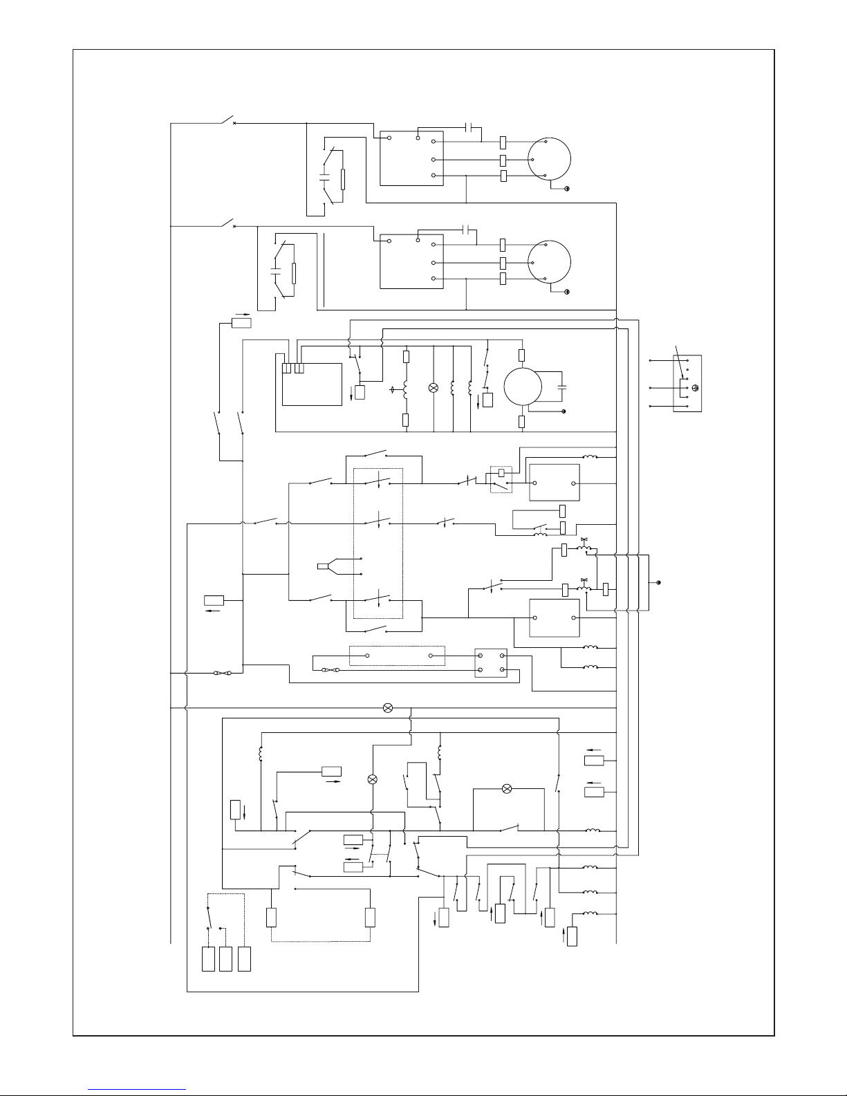
INTERNAL MACHINE CIRCUIT DIAGRAM - AIRTHERM 4.5 AND 9
L
COMPRESSOR
1
TB 11
TB 12
TB 10
TB 1
TB
2
TB
6
3
5 2
8
A2
A2A1
A1
R2
R2
R2
R5
R5
7
4
4
7
R2
1
2
A2
A1
R1
SMART
STARTER
COMPRESSOR 1
SMART STARTER
COMPRESSOR 1
LINK FOR SIMULTANEOUS
HOT WATER AND HEATING
RUN
CAP
ON
N
L1
R
N
S
RC
C H
HP SWITCH
400PSI AUTO RESET
DIG STAT
LIVE GO SIGNAL
FOR HOT WATER
NEUTRAL
1
9
MAINS
LAMP
5A
FUSE
NEUTRAL
(RED)
LIVE GO SIGNAL
FOR HEATING
DEFROST
VALVE
DEFROST LAMP
FAN
FAN CAP
(GREEN)
2019
21 22
TB 4
TB 5
BYPASS ROOM
HEATING
ROOM HEATING
N
TB 9
LIVE GO SIGNAL
FROM ROOM STAT
FOR HEATING
R3
A1
A2
R7
A1
A2
R8
8 5
9 6
R7
8 5
R7
9 3
TB14
R8
A1
A2
TB15
BUFFER
TANK
HEATING
DEMAND
PROGRAMMED
TIMED
WATER
PERIOD
R3
4
7
1
R6
8
2
5
9
3
TB13
LIVE GO SIGNAL
FOR WATER HEATING
FROM STAT DEMAND
R7
7 4
R8
7 1
4 7
R6
1
R3
9 6
R6
R8
A2A1
R6
A2A1
R4
7 4
16 17 18
6
TB
24
ELECTRIC BOX
EARTH STUD
LIVE GO SIGNAL
FOR HEATING PUMP
ON Y AND W PLAN ONLY
9 6
TB29 TB30
R4
R4
PROGRAMMER LIVE PRESENT
(RED)
TO Y PLAN
HEATING
VALVE
FROM
PROGRAMMER
4 7
1
3
9
6
PF
CAP
RESISTOR
100 OHM
R9R9
214
3
DEFROST
THERMOSTAT
R1
7
4
3
5
OUT1
C
H
HP SWITCH 430PSI
FAULT
LAMP
(AMBER)
PROBE
10 12
R4
8
5
TECNOLOGIC
(N/O)
(N/O)(N/C) (COM) (COM)
(COM) (N/O)
(N/C)
(N/O)
(COM)
(COM) (COM)
(N/O) (N/O)
(N/C) (N/C)
(N/O) (COM)
(COM)
(N/O)
(N/O)
(N/C)
(COM) (COM) (N/C)
(N/C)
(COM)
(COM)
(N/O) (N/C)
(N/C)
(N/C)
(N/O)
(N/O)
(N/O)
(N/O)
(COM)
(COM)
(COM)
(COM)
(COM)
(COM)
(N/C)
(N/O)
(N/O) (COM)
(COM)
(COM)(N/O)
(N/O)
(N/O) (N/C)
(N/C)
(COM)
(COM)
(COM)
(N/O)
BREAKS TO 'L' ON
PRESSURE RISING
BREAKS TO 'L' ON
PRESSURE RISING
C
R
S
A2
A1
R9
DIG STAT
2 STAGE
MAKE ON FALL
SAFETY WARNING
WITH BUFFER TANK THERMOSTATIC IMMERSION
HEATING. THE IMMERSION THERMOSTAT MUST BE
WIRED IN SO THAT IT CUTS OUT IMMERSION
HEATER ON OVER TEMPERATURE, MAX SETTING
55 deg C
A2
A1
R10
33 32
VOLT FREE TERMINALS
FOR BUFFER TANK
IMMERSION HEATER
(Thermostatic type)
AMBIENT STAT
MAKE ON
LOW TEMP
-2ºC to 12ºC
6
4
6
8
OUT2
P
1
(N/O)
(COM)
(N/O)
(N/O)
(COM)
9
6
(N/O)
(COM)
R1
TB
8
R5
6 9
SMART STARTER BUILT IN DELAYS
1. ON POWER UP/INTERRUPTION
OR GO SIGNAL OFF COMPRESSOR
MOTOR DOES NOT START UNTIL 3
MINUTES HAVE ELAPSED.
2. IF COMPRESSOR MOTOR DOES
NOT START A FURTHER 5 MINUTES
NEED TO ELAPSE BEFORE
RESTART BY SMART STARTER IS
ATTEMPTED.
P
2
(N/C)
(COM)
1
TB 34
TB 35
TB 36
(N/O)
ABOVE 12ºC
AMBIENT AIR
THERMOSTAT OPTION
RANGE -2º TO +12ºC
15A MAX
SWITCHING AC1
Page 12
12
INSTALLATION
Ideal airtherm - Air Source Heat Pump - Installation
INTERNAL MACHINE CIRCUIT DIAGRAM - AIRTHERM 12
SAFETY WARNING
WITH BUFFER TANK THERMOSTATIC IMMERSION
HEATING. THE IMMERSION THERMOSTAT MUST BE
WIRED IN SO THAT IT CUTS OUT IMMERSION
HEATER ON OVER TEMPERATURE, MAX SETTING
55 deg C
L
N
22
24
19
21
7
4
9
6
COMPRESSOR
1
COMPRESSOR
2
TB 9
TB 11
TB 12
TB 10
TB 1
TB
2
TB
6
3
6
5
2
8
A1A2
R2
R2
4
7
R2
R4
A2 A1
R4 R4
A2
A1
R1
2 BCM1 BCM
4 MIN
DELAY ON
TIMER
SMART
STARTER
COMPRESSOR
1
SMART STARTER
COMPRESSOR 2
SMART STARTER
COMPRESSOR 1
SMART
STARTER
COMPRESSOR
2
RUN
CAP
RUN
CAP
ON ON
NN
L1
L1
R
R
N
N S
S
RC
RC
C
H
C H
HP SWITCH
400psig
AUTO-RESET
HP
SWITCH
430psig MANUAL RESET
DIG STAT
DIG STAT
3 STAGE
MAKE ON
FALL
OUT1 OUT2
LIVE GO SIGNAL
FOR HOT WATER
LIVE GO
SIGNAL
FROM ROOM STAT
NEUTRAL
NEUTRAL
LIVE GO SIGNAL
FOR HEATING
FAULT
LAMP
MAINS
LAMP
(RED)
(AMBER)
9
13
14
LINK FOR SIMULTANEOUS
HOT WATER AND HEATING
DEFROST
VALVE
DEFROST LAMP
FAN
FAN CAP
(GREEN)
5AFUSE
BREAKS ON
COMPRESSOR
DISCHARGE PIPE
TEMP ABOVE
115 DEG
P
1
1 3
TB 4
TB 5
BYPASS
ROOM
HEATING
ROOM
HEATING
R6
A1 A2
9
3
R6
R3
A1
A2
R3
4
7
1
R7
7 4
15
18
A1
A2
R5
A1
A2
R5 R5
9
6
7
4
PROBE
4 7
R6
R6
8
2
5
R7
A1
A2
R3
9 6
R8
8 5R89 6
R7
8 5R79 3
TB 14
TB
8
1
R8
7 1
R8
A1
A2
TB 15
TB
13
LIVE GO SIGNAL
FOR WATER HEATING
BUFFER TANK
HEATING
DEMAND
PROGRAMMED
TIMED
WATER
PERIOD
FROM STAT DEMAND
7 4
R9
A1 A2
(SOPAC
JAEGER)
(1)
(2)
TECASA
R5
8
5
ELEC
BOX
EARTH STUD
TB
24
LIVE GO SIGNAL
FOR HEATING PUMP
ON Y AND W PLAN ONLY
9 6
TB
29
TB
30
R9
R9
PROGRAMMER LIVE PRESENT
(RED)
TO Y PLAN
HEATING
VALVE
FROM
PROGRAMMER
214
3
DEFROST
THERMOSTAT
R1
7
4
4 7
1
3
9 6
PF
CAP
RESISTOR
100 OHM
R11R11
A2
A1
R10
A2
A1
R11
R2
17
18
OUT3
A2
A1
R12
VOLT FREE
TERMS FOR
BUFFER TANK
IMMERSION
HEATER
(Thermostatic type)
AMBIENT STAT
-2ºC to +12ºC
MAKE ON
LOW TEMP
6
4
TRANSFORMER
230V
12V
R9
8
5
1
MAKES ON
SUCTION TEMP
ABOVE -5 DEG
C
L
ELEC BOX
EARTH STUD
LIQUID
LINE
SHUT OFF
VALVE
H
LIQUID
LINE
SHUT OFF
VALVE
(5T)
(3T)
1AFUSE
P
1
SUPPLY
(COM)
(COM)
(N/C)
(N/O)
(N/O)
(N/O)
(COM)
(COM)
(COM)
(N/C)
(COM)(N/O)
(COM)
(N/C)
(COM)
(COM)
(N/O)
(N/O)
(N/C)
(COM)
(COM)
(N/O)
(N/O)
(COM)
(COM)
(N/C)(N/C)
(N/C)
(COM)
(COM)
(COM)
(N/O)
(N/O)
(COM)
(COM) (COM)
4 7
1
3
9
6
PF
CAP
RESISTOR
100 OHM
R10R10
(COM) (COM)
(N/C)
(N/C)
(N/C)
(N/C)
(COM)(COM)
(COM)
(COM)(COM)
(COM)
(COM)
(COM)
(N/O)
(N/O)(N/O)
(N/O)
(N/O)
(N/O)
(N/O)
(N/O) (N/O)
(N/O)
(COM)
(N/O)
(COM)
(N/C)
(N/O) (N/O)
(N/C)
FAN ELECTRICAL
CONNECTIONS
N PE L
BROWN
BLUE
GRN/YEL
TWTW N
L
WHITE 0,5mm
WIRE
LINK IN TERMINAL
BOX
TO BE
ADDED
R1
9
6
(COM)
(N/O)
19
20
21
16
17
18
26
25
2827
32
23
33
31
22
SMART STARTER BUILT IN DELAYS
1. ON POWER UP/INTERRUPTION OR
GO SIGNAL OFF COMPRESSOR
MOTOR DOES NOT START UNTIL 3
MINUTES HAVE ELAPSED.
2. IF COMPRESSOR MOTOR DOES
NOT START A FURTHER 5 MINUTES
NEED TO ELAPSE BEFORE RESTART
BY SMART STARTER IS ATTEMPTED.
SEE NOTE ABOVE
15A MAX SWITCHING
AC1
P
2
(N/C)
(COM)
1
TB 34
TB 35
TB 36
(N/O)
ABOVE 12ºC
AMBIENT AIR THERMOSTAT
OPTION RANGE -2ºC to 12ºC
Page 13

13
INSTALLATION
Ideal airtherm - Air Source Heat Pump - Installation
Frost protection of the heating circuit is essential. We recommend the use of a combined inhibitor/anti-freeze, either Fernox Alphi
11 or Sentinel X500. The manufacturers’ recommendations on concentration should be followed.
A minimum concentration of 15% to 20% is needed to avoid any risk of corrosion. A 30% concentration gives frost protection down
to -15oC, the minimum operating temperature for the ASHP.
When an inhibitor/anti-freeze is used, the water ow and pressure drop need to be increased to the levels shown below.
FROST PROTECTION
Correct water ow is essential for reliable operation of the heat pump. Using the information in the table above and total system
pressure drop the selection of an appropriate water circulation pump can be made. Consult water circulation pump manufactures
data sheets for accurate water pump performance.
When the correct water pump has been selected a Delta ‘T’ of 3
o
C to 5oC between water in-let to outlet temperature indicates
correct ow rate.
Where frost protection is provided by the thermostats that control the unit, the water ow and pressure drop should be set to the
values shown in the data sheet on page 17 of this manual.
LEGEND
A Space Heating Temperature Controller
B Mains Lamp (red)
C Defrost Lamp (Green)
D Programmer Live Lamp (red)
E High Pressure Switch Manual Reset
F Fault Lamp (amber)
(contact service engineer if high
pressure reset does not clear fault)
HEATING ºC
U
P
HEAT
PUMP
DEFROST
IF LIGHT SHOWS,
PRESS RED BUTTON
POWER
PROGRAMMER
LIVE
A
B
DC F
E
at9633
CONTROL PANEL
airtherm 4.5 airtherm 9 airtherm 12
Water ow +/-20% litres/min 8.3 16.5 22.0
Pressure drop (water) Metres head 1.7 1.0 0.5
The control panel is located on the right side of the
unit under the upper removable steel panel.
1. To access, carefully remove the plastic screw
covers and the screws and washers beneath.
Place these to one side, ready for re-assembly.
2. Slide the controls cover from the upper location
slots and place to one side.
3. Re-assembly is in reverse order, taking care to
use the washers correctly to enable the screw
caps to be replaced.
2
1
All units have integral safety devices to protect the heat pump from integral and
external faults and indicator lamps showing operating mode. An adjustable
digital thermostat controls space heating and return water temperature. Also a
three minute cycle time delay which protects the compressor is incorporated.
Page 14

14
INSTALLATION
Ideal airtherm - Air Source Heat Pump - Installation
COMMISSIONING
a. Ensure that all water circuits are clean, purged, leak tested,
fully de-aerated and correctly balanced.
b. Add inhibitor/anti-freeze in the correct concentration to
ensure frost protection. This is essential, unless frost
protection is ensured by thermostats.
c. The control panel for the air source heat pump is located
under a secure cover on the right hand side of the machine.
d. Check that all wire connections are correctly made and tight
e. Switch on power at the distribution board and check that
there is mains power to the unit.
f. Check that the control system is switched on and that the
red ‘programmer live’ lamp is lit.
The space heating temperature controller is used to adjust the
return water temperature from the space heating system. For
maximum economy, this should be set to the lowest acceptable
level.
The setting is adjusted by rst pressing and then releasing
button P followed by pressing the up or down arrow buttons to
display the required temperature. Button P should be pressed
again to conrm your settings.
After 5 seconds the display will revert to the actual water
temperature.
The amber fault lamp indicates a possible problem in the
system. This may be cleared by the manual reset of the
high pressure switch (red recessed button). If the fault
proves difcult to clear, check that all plumbing and electrical
connections are made in accordance with this manual and that
the system characteristics required in the data sheet on page
16 of this manual (water ow rates etc) have been achieved.
The green defrost lamp is illuminated when the heat pump is
defrosting.
g. DHW system tests
i. Set the programmer to DHW and set the cylinder stat to
the required temperature
ii. Switch the heat pump on. Whenrstturnedon,the
machinewillgointodefrostwiththecompressorrunning,
thefanoffandthegreenlighton.Thisdefrostcyclewill
runforabout4minutes.
iii. Check that the system valves operate correctly
iv. Check for an increase of 2-3
o
C in the return water
temperature displayed on the unit control panel. This will
conrm that the system is working.
h. Central heating system tests
i. Set the programmer to central heating.
ii. Turn the room thermostat up to 30
o
C, at which point
the water circulating pump should start followed by the
compressor and fan. Note; there may be a time delay of
6 mins before the compressor starts - this is normal.
iii. Check that the system valves operate correctly
iv. Check for an increase in the return water temperature
and for an increase in the radiator temperatures. The
initial heat-up of an under oor system will take many
hours.
v. Once the system is running correctly, turn any
thermostatic radiator valves to the required settings and
set the room thermostat to 21/22
o
C.
i. Check that the chosen electricity tariff provides the optimum
economy in relation to the occupant’s lifestyle and heating
demand. When replacing electric storage radiators, note that
the Economy 7 or equivalent tariff may not be appropriate for
the economic operation of an air source heat pump.
j. Check that the time clock is set to suit the occupant. Where
a controller is tted which features multiple time/temperature
periods, set these individually to suit the occupant.
k. Ensure that all service panels are securely tted with the
tamper proof screws.
l. A fault nding chart is provided on page 15 of this manual.
m. Complete the commissioning sheet on page 34 of this
manual.
HANDING OVER
a. Hand the user instructions to the householder and explain
his/her responsibilities under the relevant regulations.
b. Explain the start and shut down procedures.
c. The operation of the heat pump and the use and adjustment
of all system controls should be fully explained to the
householder, to ensure the greatest economy consistent
with heating and hot water household requirements.
d. Advise the user of the precautions necessary to prevent
damage to the system and heat pump.
e. Explain the function of pump fault light.
f. Loss of system water pressure - Explain that the system
pressure gauge indicates the central heating system
pressure and that if the normal COLD pressure of the system
is seen to decrease over a period of time then a water leak
is indicated. Explain the re-pressurising procedure and if
unable to re-pressurise or if the pressure continues to drop a
registered local heating installer should be consulted.
Page 15

15
INSTALLATION
Ideal airtherm - Air Source Heat Pump - Installation
FAULT FINDING
a. The user checklist below should be carried out before initiating a service call.
b. Do not attempt to interfere with any internal control settings as these have been factory calibrated and sealed.
c. If in doubt or if advice is required, contact the Ideal Service department on 01482 492251.
LAMP ACTION
UNIT DOES NOT OPERATE
POWER
FAULT
DEFROST
PROGRAMMER LIVE
MAINS
FAULT
DEFROST
PROGRAMMER LIVE
POWER
FAULT
DEFROST
PROGRAMMER LIVE
RED
AMBER
GREEN
RED
RED
AMBER
GREEN
RED
RED
AMBER
GREEN
RED
OFF
OFF
OFF
OFF
ON
OFF
OFF
OFF
ON
ON
OFF
ON
Check mains supply - external fuses - isolator etc.
Check supply to programmer
Check water and air flows are not restricted
Check Heating pump(s)
FAN OFF COMPRESSOR ON
NO ROOM HEATING OR HOT WATER - UNIT NOT OPERATING
POWER
FAULT
DEFROST
PROGRAMMER LIVE
RED
AMBER
GREEN
RED
ON
OFF
ON
ON
Unit on defrost
Check evaporator is clean
POWER
FAULT
DEFROST
PROGRAMMER LIVE
RED
AMBER
GREEN
RED
ON
OFF
OFF
ON
Is programmer set to an "ON" period
Check input in terminal 1 or 9
NO ROOM HEATING OR HOT WATER - UNIT OPERATING
POWER
FAULT
DEFROST
PROGRAMMER LIVE
RED
AMBER
GREEN
RED
ON
OFF
OFF
ON
Check domestic heating system
AT9634
The machine is tted with a “Smart Starter” (situated on electrics panel) which prevents damage to the compressor within the heat
pump. This smart starter has an LED which indicates fault conditions as follows:
- Ready to accept a start command: a double blink every 5 seconds.
- 3 minute cycle delay: 1 ash per second.
- Fault mode: slow ash, 5 sec on, 5 sec off.
- Low voltage: fast ash, 10 per second.
Page 16

16
INSTALLATION
Ideal airtherm - Air Source Heat Pump - Installation
DHW Priority
Dem a nd V al ve position
Signal s To Va lve
(230V)
Inputs into ASHP
(230V)
Outputs from
ASHP (230V) Note s
DHW Only DHW OPEN TB13 TB1, TB14, TB30 TB13 output on TB4, TB24 not used
Both** DHW OPEN TB13 TB1, TB14, TB9, TB30 TB13 output on TB4, TB24 not us ed
Heating only HEATING OPEN TB10 TB9, TB30 TB10 output on TB4, TB24 not used
Defrost HEATING OPEN TB10
TB30,TB9, or TB14,
TB1, TB30 TB10,TB5 out put on TB4,TB24, TB29 not us ed
DHW & Heating
Note : Link IN - ASHP T B11 & TB12
Dem a nd V al ve position
Signal s To Va lve
(230V
)
Inputs into ASHP
(230V)
Outputs from
ASHP (230V) Notes
Notes
Notes
Notes
DHW Only DHW OPEN TB13 TB1,TB14,TB30 TB13 output on TB4, TB24 not used
Both HEATING & DHW OPEN TB10, TB13 TB1, TB14, TB9, TB30 TB13, TB10 output on TB4, TB24 not us ed
Heating only HEATING OPEN TB10 TB9, TB30 TB10 output on TB4, TB24 not used
Defrost HEATING OPEN TB10
TB30,TB9 or TB14,
TB1, TB30 TB10, TB5 output on TB4,TB24, TB29 not used
Buffe r De mand
via Buffer t ank stat and ambient stat
Dem a nd V al ve position
Signal s To Va lve
(230V)
Inputs into
ASHP
(230V)
Outputs from
ASHP (230V)
DHW Only HEATING & DHW OPE N TB10, TB13
TB1,TB14 & TB15,
TB30 TB10, TB5, TB13 Buffer Tank heated to setting
Both HEATING & DHW OPEN TB10, TB13
TB1,TB14,TB9, TB15,
TB30 TB10, TB5, TB13 Buffer Tank heated to setting
Heating only HEATING OPEN TB10 TB9, TB15, TB30 TB10 Buffer Tank already being heated
** Progra mme r should be set to sepa ra te DHW a nd Heating tim e pe riodsNote : Link OUT - AS HP TB11 & TB12
ASHP Operation Check List S-Plan System
DHW Priority
Notes: Link OUT - ASHP TB11 & TB12 **Programme r should be set to sepa rate DHW & Heating time periods
Dema nd Valve position Signals to Valve
Inputs into ASHP
(230V)
Outputs from
ASHP (230V)
DHW Only spring return to DHW none TB1 & TB14, TB30 230V TB24 output on TB4, TB13 not used
Both** spring return to DHW none TB1, TB14, TB9, TB30 230V TB24 output on TB4, TB13 not used
Heating only heating open 230V from TB10 TB9, TB30
230V on TB10,
TB24 output on TB4 not used
Defrost heating open 230V fr
om TB10
TB30, TB9 or TB1,
TB14, TB30
230V on TB10 &
TB5, TB24 output on TB4, TB29 not used
Buffer Demand
via Buffer tank stat and ambient stat
Dema nd Valve position Signals to Valve
Inputs into ASHP
(230V)
Outputs from
ASHP (230V)
DHW Only Heating- open 230V from TB10
TB1, TB14, TB15,
TB30
230V on TB10,
TB5, TB24 Buffer Tank heated to setting
Both Heating- open 230V from TB10
TB1, TB14, TB9 TB15,
TB30
230V on TB10,
TB5, TB24 Buffer Tank heated to setting
Heating only Heating- open 230V from TB10 TB9, TB15
, TB30
230V on TB10,
TB5, TB24 Buffer Tank already being heated
ASHP Operation Check List W-Plan System
Page 17

17
INSTALLATION
Ideal airtherm - Air Source Heat Pump - Installation
DATASHEET
NOTES.
1. Weight and dimensions nett
2. Application limits: Lower limit of use to EN14511-4-2007, Outside heat exchanger = -6ºC.
Potential Design lower limit of use, Outside heat exchanger = -15ºC
Lowest entering temperature to EN14511-4-2007, Inside heat exchanger (water on) = 20ºC
(To ensure satisfactory defrosting this assumes industry standard water heat up times from 10ºC to nominal UFH temperature of 35ºC)
Higher limit of use to EN14511-4-2007 Outside heat exchanger = 35ºC
Potential Design higher limit of use, Outside heat exchanger = 45ºC
Higher limit of use to EN14511-4-2007 Inside heat exchanger (water off) = 65ºC
3. Allow 500mm clearance to service panels
4. Ideal reserve the right to change or modify models without prior notice
5. R134A global warming potential (GWP) 1300
6. The C.O.P. applies to NEW units with CLEAN heat exchangers.
* OUTDOOR HEAT EXCHANGER INLET TEMPERATURE
# INDOOR HEAT EXCHANGER OUTLET TEMPERATURE
SPECIFIC PERFORMANCE CURVES CAN BE SUPPLIED BY IDEAL ON REQUEST
1m hd = 1.4 psi
1l/min = 0.22 gall
MODEL UNITS AIRTHERM 4.5 AIRTHERM 9 AIRTHERM 12
DUTY
Air on 0
o
C 90% RH *(@ DESIGN WATER FLOW)
OUTPUT TO WATER (@55oc) # kW 2.97 5.63 7.86
ELECTRICAL INPUT kW 1.54 2.93 3.98
OUTPUT TO WATER (@35oc) # kW 3.39 6.56 9.11
ELECTRICAL INPUT kW 1.11 2.17 2.93
Air on 7oC 87% RH *(TO EN 14511-2-2007)
OUTPUT TO WATER (@35oc) # kW 4.40 8.40 11.70
ELECTRICAL INPUT kW 1.18 2.27 3.13
C.O.P. (SEE NOTE 6) 3.72 3.70 3.70
Air on 2oC 60% RH *(@ DESIGN WATER FLOW)
OUTPUT TO WATER (@55oc) # kW 6.10 11.44 15.92
ELECTRICAL INPUT kW 1.78 3.35 4.54
OUTPUT TO WATER (@35oc) # kW 6.30 11.81 16.50
ELECTRICAL INPUT kW 1.37 2.58 3.51
DUTY
ELECTRICAL SUPPLY 1 PHASE V/ph/Hz 230/240V-1N/50Hz
MINIMUM SUPPLY CAPACITY amps 13 25 32
AMBIENT 10
o
c WATER 24oC kWh 1.8 2.3 3.1
AMBIENT 20oC WATER 24oC kWh 2 2.5 3.3
MAXIMUM SUPPLY FUSE 1ph N/ TYPE C MCB amps 15.0 32.0 40.0
MAXIMUM STARTING CURRENT STD (LRA) 1 ph amps 58.0 108.0 76.0
RLA 1ph amps 10.1 18.8 12.9
SOFT START AMPS 1ph N amps 19 35 31
IP Rating 24 24 24
WATER FLOWS ETC.
WATER FLOW ± 20% litres/min 7.5 15 20
PRESSURE DROP (WATER) metres hd 1.1 0.7 0.4
CONDENSER VOLUME litres 2.0 3.5 6.5
WATER CONNECTIONS inches 3/4” BSPM 3/4” BSPM 1” BSPM
CONDENSATE WATER CONNECTIONS inches 3/4” DOMESTIC WASTE
MAIN FAN
AIR FLOW (Anemometer @ air on grille. Wet evaporator) m3/hr 3266 3000 4330
MAX EXTERNAL STATIC PRESSURE STD mm Wg 0 0 0
MAX EXTERNAL STATIC PRESSURE F mm Wg 6 6 6
FLA:- 1 ph N amps 0.7 0.7 0.7
GENERAL DATA
Hermetic System
GAS CHARGE R134a kg 3.5 5.5 7.5
OIL TYPE (COMPRESSOR) POLYOLESTER OIL
PHYSICAL DIMENSIONS
WIDTH (Un-packed) mm 1145 1145 1585
DEPTH (Un-packed) mm 567 567 617
HEIGHT (Un-packed) mm 958 958 958
WEIGHT (Un-packed) kg 127 164 235
SOUND PRESSURE @ 1 metre dB(A) 57 58 60
SOUND PRESSURE @ 10 metre dB(A) 37 38 40
SOUND POWER TO ENV 12102 dB(A) 68 69 71
Page 18

18
INSTALLATION
Ideal airtherm - Air Source Heat Pump - Installation
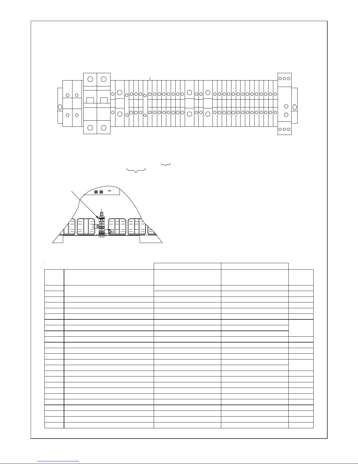
MACHINE DIMENSIONS, ACCESS PANELS AND ELECTRICAL/WATER CONNECTIONS
AIRTHERM 4.5
WARNING. DANGER FROM ELECTRIC SHOCK. ISOLATE ALL ELECTRICAL SUPPLIES BEFORE REMOVING ANY PANELS
WATER IN/OUT CONNECTIONS 3/4" BSPM STUBS.
CONDENSATE CONNECTION 3/4" BSPM STUB.
ALLOW 500mm FOR ACCESS TO SERVICE PANELS
SEE WIRING DIAGRAMS
CUSTOMERS ELECTRICAL CONNECTIONS
AIR ON
EVAPORATOR
PANEL
(REMOVABLE)
FAN PANEL
(REMOVABLE)
1107
958
36
95.5
AIR OFF
AIR ON
TOP PANEL
(REMOVABLE)
CABLE ENTRY
129
128
172
298
163
296
WATER OUT
WATER IN
CONDENSATE
DRAIN
ELECTRICS
ACCESS
PANEL
CONSOLE
COVER
567
1145
1 2
16
L N 3
4 5 6
7 8 9 10
11
12
ETH
ETH
13 14
15 17
42 9202 12 2281 91 30 32 33
Page 19

19
INSTALLATION
Ideal airtherm - Air Source Heat Pump - Installation
MACHINE DIMENSIONS, ACCESS PANELS AND ELECTRICAL/WATER CONNECTIONS
AIRTHERM 9
WARNING. DANGER FROM ELECTRIC SHOCK. ISOLATE ALL ELECTRICAL SUPPLIES BEFORE REMOVING ANY PANELS
WATER IN/OUT CONNECTIONS 3/4" BSPM STUBS.
CONDENSATE CONNECTION 3/4" BSPM STUB.
ALLOW 500mm FOR ACCESS TO SERVICE PANELS
SEE WIRING DIAGRAMS
CUSTOMERS ELECTRICAL CONNECTIONS
AIR ON
EVAPORATOR
PANEL
(REMOVABLE)
TOP PANEL
(REMOVABLE)
FAN PANEL
(REMOVABLE)
1107
958
36
95.5
CABLE ENTRY
128
128
208
163
406
WATER
OUT
CONSOLE
COVER
WATER
IN
CONDENSATE
DRAIN
ELECTRICS
ACCESS
PANEL
567
300.5
1145
1 2
16
L N 3
4 5 6
7 8 9 10
11
12
ETH
ETH
13 14
15 17
42 9202 12 2281 91 30 32 33
AIR OFF
AIR ON
Page 20

20
INSTALLATION
Ideal airtherm - Air Source Heat Pump - Installation
MACHINE DIMENSIONS, ACCESS PANELS AND ELECTRICAL/WATER CONNECTIONS
AIRTHERM 12
WARNING. DANGER FROM ELECTRIC SHOCK. ISOLATE ALL ELECTRICAL SUPPLIES BEFORE REMOVING ANY PANELS
WATER IN/OUT CONNECTIONS 1" BSPM STUBS.
CONDENSATE CONNECTION 3/4" BSPM STUB.
ALLOW 500mm FOR ACCESS TO SERVICE PANELS
SEE WIRING DIAGRAMS
CUSTOMERS ELECTRICAL CONNECTIONS
AIR ON
EVAPORATOR
PANEL
(REMOVABLE)
TOP PANEL
(REMOVABLE)
36
95.5
958
FAN PANEL
(REMOVABLE)
1547
128
168
411
152.5
220.5
617
CABLE
ENTRY
WATER OUT
WATER IN
CONDENSATE
DRAIN
ELECTRICS
ACCESS
PANEL
CONSOLE
COVER
1585
24 29 30
25
L N
1
2
3 4 5 6 7 8 9 10
11
12
ETH
ETH
13 14
15 17 18 20
21 22 23
26 27 28
31
A1 15 Y1
16 18 A2
32 33
16 19
AIR OFF
AIR ON
Page 21

21
INSTALLATION
Ideal airtherm - Air Source Heat Pump - Installation
SYSTEM DIAGRAMS -
Air Source Heat Pump Plumbing Circuits - S Plan (example) preferred method
3
1A
1B
2
COLD WATER TANK
HOT WATER
COLD WATER
PRESSURE AND
TEMPERATURE
RELIEF VALVE
(IF FITTED)
TUNDISH
(IF FITTED)
DHW
THERMOSTAT
SET TO 60
O
C
DIFF SET TO 8
O
C
*TO WASTE. WARNING CONSISTS OF
SCALDING WATER AND STEAM.
DISCHARGE BELOW FIXED GRATING
IN ACCORDANCE WITH BUILDING
REGULATIONS.
AMBIENT
STAT 1 0
O
C
STAT
25
O
C
IF FITTED
A
A
X
A
AB
DWELLING HEATING
SYSTEM
2 PORT SPRING RETURN VALVE DHW1A
2 PORT SPRING RETURN VALVE ROOM HEATING
NOTE: IF ROOM HEATING IS VIA RADIATORS RATHER THAN UNDERFLOOR HEATING THEM VALVE 2 AND THE PIPE RUN X-X ARE NOT REQUIRED.
B
X
B
B
AIRTHERM 4.5 = 50 LITRES
AIRTHERM 9 = 100 LITRES
AIRTHERM 12 = 150 LITRES
IF FITTED
(OPTIONAL)
*2 PORT SAFETY CUT OUT VALVE FITTED IN
INDIRECT PRESSURISED CYLINDERS
PROGRAMMER
(e.g. DANFOSS FP175)
OUTSIDE SENSOR
PART OF WEATHER
COMPENSATION UNIT
(IF FITTED)
JUNCTION BOX
FROST STAT
WEATHER
COMPENSATION
UNIT (IF FITTED)
DWELLING ROOM
THERMOSTAT WITH
ON OFF SWITCH
EXPANSION VESSEL
(IF FITTED)
EXPANSION
RELIEF VALVE
(IF FITTED)
IMMERSION HEATER
WITH THERMOSTATIC CUT OUT
THERMOSTAT MANUAL RESET
TO BE SET AT 65
O
C (IF FITTED)
DRAIN COCK
DHW TANK
A B
PUMP
AIR SOURCE
HEAT PUMP
BUFFER
TANK
DIRECT
A
D
F
H E
B
G
C
WIRED FOR
'DHW' PRIORITY
OR
'BOTH' PRIORITY
(ACTS AS BOILER)
HEATING FLOW
TEMPERATURE SENSOR.
PART OF WEATHER
COMPENSATION UNIT
(IF FITTED)
45
O
C
SEE NOTE
VALVE THERMOSTATIC FLOOR BYPASS VALVE (IF REQUIRED)
SET TO 45
O
C
2
VALVE 'DEFROST' REQUIRED VALVE' = DIVERTER VALVE
'AB' TO 'B' = ROOM HEATING ALLOWED
'AB' TO 'A' = NO ROOM HEATING (DEFROST SIGNAL FROM HEAT PUMP)
3
1B
AT9642
Page 22

22
INSTALLATION
Ideal airtherm - Air Source Heat Pump - Installation
SYSTEM DIAGRAMS -
External Wiring with Terminal Junction Box - S Plan
1 MAXIMUM RATING OF CONTACTS FOR PUMP 1A. IF OVER 1A RELAY WILL NEED TO BE FITTED.
2 AIR SOURCE HEAT PUMP TERMINAL 8 IS CONTROL LIVE TEST TERMINAL.
3 ALL VALVES TO BE SPRING RETURN TYPE.
4 ALL EXERNAL EQUIPMENT TO BE FUSED TO MANUFACTURERS RECOMMENDED FUSE SIZES.
5 MIN CABLE REQUIREMENTS 3 CORE MAINS CABLE, 12 CORE CONTROL CABLE
6 A
7 WHEN FITTING BUFFER TANK THERMOSTATIC IMMERSION HEATING,
THE IMMERSION THERMOSTAT MUST BE WIRED SO THAT IT CUTS OUT ON OVER TEMPERATURE,
MAX SETTING 55ºc
SSOCIATED EXTERNAL EQUIPMENT AND MACHINE TO BE WIRED FROM SAME CONSUMER
UNIT AND TAKEN FROM THE SAME PHASE AND NEUTRAL INCOMING SUPPLY.
NOTES
8
L
6 10123 5 7 94
6 9 10123 5 7 84 1 6 1911 12 13 15 17 1814
4
N
L1 32
LN
2 PORT VALVE
HONEYWELL
V4043
HOT WATER
DOMESTIC
2 PORT
VALVE
HONEYW ELL
V4043
ROOM
HEATING
ROOM
THERMOSTAT
DOMESTIC
HOT WATER
THERMOSTAT
PROGRAMMER
TERMINAL
JUNCTION
BOX
AIR SOURCE HEAT PUMP INTERNAL TERMINALS
NEN L E N L NELL L LL
HW CH
LNE L LNE L L
LNE
LN
SWITCHED FUSED SUPPLY
230V ~ 1N
9005 = 32A/32A MCB TYPE C
12005 = 40A/40A MCB TYPE C
HIGH LEVEL
MANUAL RESET
THERMOSTAT
HIGH PRESSURE
CYLINDER ONLY
1211
LL
LINK FOR
HOT WATER
AND HEATING
CYLINDER
VALVE HIGH
PRESSURE
CYLINDERS
ONLY
ROOM HEATING (NOT USED)
BYPASS ROOM HEATING
4505 = 15A/16A MCB TYPE C
FROST
STAT
2120
L
M
M
AUX
CONTACTS
AUX
CONTACTS
SINGLE PHASE
FIXED SPEED
PUMP - SEE NOTE 1
13L1514
LL
BUFFER TANK
STAT MAKE ON
BELOW
TEMPERATURE
AMBIENT STAT
MAKE ON
BELOW
TEMPERATURE
30
L
FUSE
SEE NOTE 2
HONEYWELL
V4044 SPRING
RETURN 3 PORT
DIVERTER
VALVE
WEATHER
COMPENSATION
UNIT
(OPTIONAL)
F4 K4
REMOVE LINK IF
WEATHER
COMPENSATION
UNIT FITTED
22
L
SEE
NOTE 4
N
23
L
BLUE
GRN/YEL
BROWN
32L33
L
L
2524L26N27
E
LN
230V ~ 1N
FUSED SUPPLY
SEE NOTE 6
SEE NOTE 6
2 CORE
CABLE
L
N
E
IMMERSION
HEATER
SWITCH
FUSE SPUR
MAX 30A
SEE NOTE 4
REQUIRED ONLY IF HIGH
LEVEL STAT NOT FITTED
IDEAL S PLAN
GUIDE ONLY
AT9646
Page 23

23
INSTALLATION
Ideal airtherm - Air Source Heat Pump - Installation
3
1
2
COLD WATER TANK
HOT WATER
COLD WATER
PRESSURE AND
TEMPERATURE
RELIEF VALVE
(IF FITTED)
TUNDISH
(IF FITTED)
DHW
THERMOSTAT
SET TO 60
O
C
DIFF SET TO 8
O
C
*TO WASTE. WARNING CONSISTS OF
SCALDING WATER AND STEAM.
DISCHARGE BELOW FIXED GRATING
IN ACCORDANCE WITH BUILDING
REGULATIONS.
AMBIENT
STAT 1 0
O
C
STAT
25
O
C
IF FITTED
A
A
X
A
AB
DWELLING HEATING
SYSTEM
3 PORT SPRING RETURN DIVERTER VALVE1
NOTE: IF ROOM HEATING IS VIA RADIATORS RATHER THAN UNDERFLOOR HEATING THEN VALVE 2 AND THE PIPE RUN X-X ARE NOT REQUIRED.
B
X
B
B
AIRTHERM 4.5 = 50 LITRES
AIRTHERM 9 = 100 LITRES
AIRTHERM 12 = 150 LITRES
IF FITTED
(OPTIONAL)
AB
B
A
*2 PORT SAFETY CUT OUT VALVE FITTED IN
INDIRECT PRESSURISED CYLINDERS
PROGRAMMER
(e.g. DANFOSS FP175)
OUTSIDE SENSOR
PART OF WEATHER
COMPENSATION UNIT
(IF FITTED)
JUNCTION BOX
FROST STAT
WEATHER
COMPENSATION
UNIT (IF FITTED)
DWELLING ROOM
THERMOSTAT WITH
ON OFF SWITCH
EXPANSION VESSEL
(IF FITTED)
EXPANSION
RELIEF VALVE
(IF FITTED)
IMMERSION HEATER
WITH THERMOSTATIC CUT OUT
THERMOSTAT MANUAL RESET
TO BE SET AT 65
O
C (IF FITTED)
DRAIN COCK
DHW TANK
A B
PUMP
AIR SOURCE
HEAT PUMP
BUFFER
TANK
DIRECT
A
D
F
H E
B
G
C
WIRED FOR
'DHW' PRIORITY
OR
'BOTH' PRIORITY
(ACTS AS BOILER)
HEATING FLOW
TEMPERATURE SENSOR.
PART OF WEATHER
COMPENSATION UNIT
(IF FITTED)
45
O
C
SEE NOTE
VALVE THERMOSTATIC FLOOR BYPASS VALVE (IF REQUIRED)
SET TO 45
O
C
2
VALVE 'DEFROST' REQUIRED VALVE' = DIVERTER VALVE
'AB' TO 'B' = ROOM HEATING ALLOWED
'AB' TO 'A' = NO ROOM HEATING (DEFROST SIGNAL FROM HEAT PUMP)
3
AT9643
SYSTEM DIAGRAMS -
Air Source Heat Pump Plumbing Circuits - W Plan (example)
Page 24

24
INSTALLATION
Ideal airtherm - Air Source Heat Pump - Installation
SYSTEM DIAGRAMS -
External Wiring with Terminal Junction Box - W Plan
230/240V ~ 1N
SWITCHED FUSED SUPPLY
4505 = 15A/16A MCB TYPE C
9005 = 32A/32A MCB TYPE C
12005 = 40A/40A MCB TYPE C
SEE NOTE 6
NOTES
1 MAXIMUM RATING OF CONTACTS FOR PUMP 1A. IF OVER 1A RELAY WILL NE ED TO BE FITTED.
2 AIR SOURCE HEAT PUMP TERMINAL 8 IS CONTR OL LIVE TEST TERMINAL.
3 ALL VALVES TO BE SPRING RETURN TYPE.
4 ALL EXERNAL EQUIPMENT TO BE FUSED TO MANUFACTURERS RECOMMENDED FUSE SIZES.
5 MIN CABLE REQUIREMENTS 3 CORE MAINS CABLE, 12 CORE CONTROL CABLE
6 ASSOCIATED EXTERNAL EQUIPMENT AND MACHINE TO BE WIRED FROM SAME CONSUMER
UNIT AND TAKEN FROM THE SAME PHASE AND NEUTRAL INCOMING SUPPLY.
8
L
6 10123 5 7 94
6 9 10123 5 7 84 1 6 1 911 12 13 15 17 1814
4
N
L1 32
LN
DOMESTIC
HOT WATER
THERMOSTAT
PROGRAMMER
TERMINAL
JUNCTION
BOX
AIR SOURCE HEAT PUMP INTERNAL TERMINALS
NEN L E N L NELL L LL
HW CH
LNE L LNE L L
LNE
LN
HIGH LEVEL
MANUAL RESET
THERMOSTAT HIGH
PRESSURE
CYLINDER ONLY
REQUIRED ONLY IF HIGH
LEVEL STAT NOT
FITTE D
1211
LL
HOT WATER AND
HEATING
LINK MUST NOT
BE FITTED
CYLINDER
VALVE
HIGH PRESSURE
CYLINDERS ONLY
ROOM HEATING (NOT USED)
BYPASS ROOM HEATING
FROST
STAT
21
20
L
M
SINGLE PHASE
PUMP
FIXED SPEED
SEE NOTE 1
13L1514
LL
BUFFER TANK
STAT MAKE ON
BELOW
TEMPERATURE
AMBIENT STAT
MAKE ON
BELOW
TEMPERATURE
30
L
FUSE
SEE NOTE 2
HONEYWELL V4044
SPRING RETURN
3 PORT DIVERTER
VALVE
GRN/YEL
BROWN
BLUE
WEATHER
COMPENSATION
UNIT
(OPTIONAL)
F4 K4
REMOVE LINK
IF WEATHER
COMPENSATION
UNIT FITTED
22
L
3 PORT VALVE
HONEYWELL
V4044
ROOM HEATING
24
L
N
SEE
NOTE 4
23
L
33L32
L
L
2524L26N27
E
L
N
E
LN
230/240V ~ 1N
FUSED SUPPLY
SEE NOTE 6
2 CORE
CABLE
SWITCH
FUSE SPUR
MAX 30A
SEE NOTE 4
IMMERSION
HEATER
ROOM
THERMOSTAT
IDEAL W PLAN
GUIDE ONLY
AT9647
7 WHEN FITTING BUFFER TANK THERMOSTATIC IMMERSION HEATING,
THE IMMERSION THERMOSTAT MUST BE WIRED SO THAT IT CUTS OUT ON OVER TEMPERATURE,
MAX SETTING 55ºc
Page 25

25
INSTALLATION
Ideal airtherm - Air Source Heat Pump - Installation
BIVALENT INSTALLATION - SCHEMATIC DIAGRAM
Heating
Rad 1
B
AB
Room
T'stat
Programmer/
timeclock
Boiler on
valve open
60 deg C
DHW
TANK
BUFFER
TANK
55 deg C
DHW Supply
Defrost
By-pass
Valve
55 deg C
70 deg C
55 deg C
NRV
50 deg C
50 deg C
Return Temp
Thermostat/sensor
Ambient
Thermostat/senso
r
20 l/min
Boiler
Heat Pump
Tank stat
set at
60
o
C
A
B
AB
A
A
B
Heating
Rad 2
Heating
Rad 3
on at 45
o
C
on at 48
o
C
set at
2 - 5
o
C
AT9638
System
By-pass
MUST
be fitted if
TRV's are
used
Page 26

26
INSTALLATION
Ideal airtherm - Air Source Heat Pump - Installation
REFRIGERATION DIAGRAM - AIRTHERM 4.5 & 9
PHIAL
E.D.C.M.
THERMOSTAT (CONSOLE)
HEATING RETURN WATER
REVERSING
VALVE
COIL
COMP
HP
SCHRADER
SERVICE
HP
SUCTION
ACCUMULATOR
TEV
PHIAL
TEV
DRIP TRAY
HEATER
DRIER
RECEIVER
CONDENSER
NRV
PORT
PROCESS
CAPILLARY
3/16" DIA X 300mm LONG
SCHRADER
SERVICE
LP
NRV
HP
430 psig
MANUAL RESET
400 psig
AUTO RESET
= INSULATION
Page 27

27
INSTALLATION
Ideal airtherm - Air Source Heat Pump - Installation
REFRIGERATION DIAGRAM - AIRTHERM 12
AIR TO WATER HEAT PUMP AIRTHERM 12
HIGH
TEMP
CUTOUT
THERMOSTAT
LOW
TEMP
CUTOUT
THERMOSTAT
COMP 1
EVAPORATOR
TEV
PHIAL
TEV
PHIAL
PROCESS
PORT
LP SERVICE
SCHRADER
TEV
RECEIVER
REVERSING
VALVE
COIL
SUCTION
ACCUMULATOR
DRIER
DRIP TRAY
HEATER
NRV
NRV
CAPILLARY
1/4" DIA X 300mm LONG
SOL VALVE
TEV
COMP 2
LP SERVICE
SCHRADER
SUCTION
ACCUMULATOR
OIL EQUALISATION
CONDENSER
EDCM
PROBE
SOL VALVE
HP
HP
SERVICE
SCHRADER
HP
430psig
MANUAL RESET
400psig
AUTO RESET
THERMOSTAT DWELLING
HEATING (CONSOLE)
HEATING RETURN WATER
= INSULATION
Page 28

28
INSTALLATION
Ideal airtherm - Air Source Heat Pump - Installation
OPTIONAL WEATHER COMPENSATION
Coding switches (item )
Setting potentiometers (items , , )
FUNCTION SWITCH POSITION ON LEFT SYMBOLSYMBOLSWITCH POSITION ON LEFT
SUGGESTED
SETTING
Base point of heating
curve
Base point at 20ºC fl ow
temperature
20ºC 35ºC
Base point at 35ºC fl ow
temperature
Set to Left
Frost protection, yes/no Yes, frost protec tion No, no frost protection Set to Right
Changeover of
compensating va riable,
yes/no
No changeover: always
weather compensated control
and room temperature
authority according to setting
potentiometer E
Changeover to room
temperat ure compensated
control at reduced level
Set to Left
Pump overrun, yes/no Six minute pump overrun 6 Min0 Min0 minutes, no pump overrunSet to Right
WEATHER COMPENSATOR UNIT
ITEM POTE NTIOMETER FUNCTION SETTING RANGEGUIDE VALUESUGGESTED SETTING
1
Switching differential
of heat pump
temperature control
1…20 K6 KSet to 5 K
4
Authority of room
temperature on heat
pump temperature
control
0…100 % authority
OFF = quick
setback is inactive
50 % (quick
setback is active)
Set to OFF
5
Heating limit for
ECO automatic
energy saver
–10…+8 °C
(referred to the room
temperature
setpoint)
–3 K (gives a
heating limit of 16
°C at a room
temperature
setpoint of 20 °C)
Function disabled: OFF
1. Setting potentiometer for switching differential.
2. Setting knob for heating curve slope.
3. Coding switches
4. Setting potentiometer for authority of room
temperature for quick setback active/inactive.
5. Setting potentiometer for ECO heating limit.
6. Heating curve chart.
LEGEND
1
2
3
3
1 4 5
4 5 6
The use of a weather compensator with Ideal airtherm heat pumps achieves greater efciency benets.
An example of using the Siemens model RVP102 follows.
Page 29

29Ideal airtherm - Air Source Heat Pump - Installation
AC 230/240V
TERMINALS IN HEAT PUMP
(TERMINAL JUNCTION BOX
ONLY), SEE NOTE 3.
CABLE SIZE CABLE LENGTH
COPPER CABLE Ø0.6mm 30m
COPPER CA BLE 0.5mm² 50m
COPPER CA BLE 1.0mm² 80m
COPPER CA BLE 1.5mm² 120m
Cable lengths
PERMISSIBLE CABLE LENGTHS TO DETECTORS AND ROOM UNIT
OUTSIDE
DETECTOR
LB9B1M F4
K4
TB14 TB15
N
RVP102
QAC22 QAD22
ROOM
THERMOSTAT
HEAT PUMP
TEMPERATURE
DETECTOR
AT9639
MOUNTING THE SENSOR
Outdoor Temperature Sensor
Mounting Location
For optimisation the sensor must be positioned on the coldest wall of the house
(normally wall facing north). The sensor must never be exposed to the morning
sun.
Mounting Height
Preferably in middle of dwelling to be heated, but at least 2.5m above the ground.
Must not be tted above windows, doors, air extracts or other heat sources, below
balconies or in the eaves of the roof.
The sensor must not be painted over.
WIRING THE OPTIONAL WEATHER COMPENSATOR (see external wiring diagram)
Notes.
1. Room thermostat enables heating pump
2. Assumed that domestic hot water will have
priority and override heating circuit.
3. If using Grundfos control box, terminal numbers
are different, see external wiring diagram.
~100 mm
MOUNTING POSITIONS
KEEP AREA AROUND
SENSOR CLEAR OF
INSULATION
STRAP ON TEMPERATURE
SENSOR
AT9649
Page 30

30
Ideal airtherm - Air Source Heat Pump - Installation
HEAT PUMP BUFFER INSTALLATION REQUIREMENTS
There are a number of main points that affect the buffer sizing requirements as follows:
1. A constant water ow of +/- 10% of design must be maintained through the heat pump. This can be achieved using good system
design. Where TRV’s or underoor heating are used special care must be taken to ensure the ow is maintained regardless of
system turn down.
2. The assumptions using combination cylinders in table1 assume that the buffer vessel is plumbed in series with the radiator circuitry
simply adding water volume to assist ow rates.
3. Table 2 shows the temperature drop in the water volume in the buffer and the heat distribution circuit as a result of providing energy
for the heat pump to perform defrost functions when necessary.
Heat Pump
System Type
TRV’s tted
Flow rate
required l/m
System water
volumes
Buffer tank
Minimum size
of buffer
Method
proposed
Minimum DHW
Cylinder
Normal DHW
Cylinder
Max DHW size
Minimum
Circulation
Pump Size
No of Pumps on
system
Typical System
Design
4.5kW radiators no 7.5
above
45 litres
No n/a
DHW cylinder
only
150
litre
150
litre
180
litre
15 - 50 1
S or W
Plan
4.5kW radiators no 7.5
below
45 litres
Yes 50 litres
combination
cylinder
150
litre
150
litre
180
litre
15 - 50 1
S or W
Plan
4.5kW radiators yes 7.5 n/a Yes 50 litres
combination
cylinder
15
0 litre
150
litre
180
litre
15 - 50 1
S or W
Plan
4.5kW underoor n/a 7.5
n/a Yes 50 litres
separate
cylinder /buffer
150
litre
150
litre
180
litre
15 - 50 2
2 pump
system
9.0kW radiators no 15
above
80 litres
No n/a
DHW cylinder
only
150
litre
180
litre
250
litre
15 - 60 1
S or W
Plan
9.0kW radiators no 15
below
80 litres
Yes 50 litres
combination
cylinder
150
litre
180
litre
250
litre
15 - 60 1
S or W
Plan
9.0kW radiators Ye s 15 n/a Yes 50 litres
combination
cylinder
150
litre
180
litre
250
litre
15 - 60 1
S or W
Plan
9.0kW underoor n/a 15
n/a Yes 95 litres
separate
cylinder /buffer
150
litre
180
litre
250
litre
15 - 60 2
2 pump
system
12kW radiators no 20
above
160 litres
No n/a
combination
cylinder
150
litre
210
litre
250
litre
15 - 60 1
S or W
Plan
12kW radiators no 20
above
110 litres
Yes 50 litres
combination
cylinder
150
litre
210
litre
250
litre
15 - 60 1
S or W
Plan
12kW radiators no 20
below
110 litres
Yes 95 litres
combination
cylinder
150
litre
210
litre
250
litre
15 - 60 1
S or W
Plan
12kW radiators Ye s 20 n/a Ye s 95 litres
combination
cylinder
150
litre
210
litre
250
litre
15 - 60 1
S or W
Plan
12kW underoor n/a 20
n/a Yes 150 litres
separate
cylinder /buffer
150 litre 210 litre
250
litre
15 - 60 2
2 pump
system
Table 1
Table 2 - Defrost Times & Temperature Drops
** Estimated from defrost tests carried out
Model Operation Condition Defrost Times - mins System Volume - ltrs System temp drop - ºC**
4.5 A5/W55 5 45 4.9
4.5 A0/W55 6 45 3.9
4.5 A-3/W55 7 45 3.8
9 A5/W55 5 80 5.5
9 A0/W55 6 80 4.4
9 A-3/W55 7 80 4.3
12 A5/W55 5 110 5.5
12 A0/W55 6 110 4.4
12 A-3/W55 7 110 4.2
Page 31

31Ideal airtherm - Air Source Heat Pump - Installation
Water Storage Requirement
The heating circulation pump takes hot water from the Airtherm unit to the thermstore water storage vessel which is a specially
designed indirect cylinder.
The following range of cylinders are available from Ideal heating. These are tted with thermostatic controls which control the
storage water temperature. The maximum DHW temperature is set in the factory at 65ºC.
Sealed Systems - Installation must comply with the requirements of BS6798 and BS5449.
Installations must be designed in excess of the maximum system operating temperature and pressures.
Safety valves must comply with BS6759.
All system components must comply with the required local water regulations.
Thermostore Cylinders Pressure Data Thermstore Coil Pressure Data
1. Inlet control to 2.1 bars (by the valve provided) 1. Coil is rated to 3.5 bars
2. The venting pressure 3.5 bars (by the valve provided) 2. Maximum operating pressure 3 bars
3. The maximum operating pressure is 3 bars
Thermstore Unvented (indirect) Cylinder
Cylinder
Type
Shell size
(mm)
Overall
dimensions
(mm)
Ideal
No
150 Litre 1100 x 450 1125 x 550 204829
180 Litre 1300 x 450 1325 x 550 204830
210 Litre 1500 x 450 1525 x 550 204831
¾” Cold Feed with
spreader pipe and
check valve fitted.
I
mmersion heater
with
integrated Stat
½” Drain
½” Stat Boss for
Control Stat
½” Boss for High Limit
Stat.
22mm Draw Off/Expansion
Expansion Vessel Boss
Relie
f Valves & Tundish
High Efficiency
22mm Coil
Page 32

32
Ideal airtherm - Air Source Heat Pump - Installation
Thermstore Unvented (direct) Buffer &
(indirect) Cylinder Combined
½″ female for
Thermostat Pocket
1″ Connection for Flow
& return For Buffer
Vessel
3 kW Immersion heater
& integrated stat
22mm Draw Off/Expansion
Expansion Vessel Boss
Relief Valves & Tundish
¾” Cold Feed
c/w Baffle and Check
Valve Fitted
½” female for High Limit
Stat
½″ Pocket Control
Thermostat
Buffer Vessel for Heating
3 kW Immersion heater
& integrated stat
1″ Flow &Return
Connections for Buffer
High Efficiency Coil
22mm Connection
½” Drain
Drain to Be Teed into one
of lower connections!
Cylinder
Type
Shell size
(mm)
Overall
dimensions
(mm)
Ideal
No
50/150 Litre
1500 x 450 1525 x 550 204835
95/180 Litre
2100 x 450 2125 x 550 204836
150/210 Litre
2150 x 500 2175 x 550 204837
Page 33

33Ideal airtherm - Air Source Heat Pump - Installation
3
kW
I
mmersion
heater & integrated
stat (2¼”)
1” Flow (Heat Pump)
½” Stat Boss for
Control Stat
½” Boss for High
Limit Stat.
1”
Returns
1” Flow (Heating)
Thermstore Unvented (direct) Buffer Cylinder
Cylinder
Type
Shell size
(mm)
Finished
Size
Ideal
No
50L Direct
450 x 450 475 x 550 204832
95L Direct
750 x 450 775 x 550 204833
150L Direct
900 x 500 925 x 600 204834
Page 34

34
Ideal airtherm - Air Source Heat Pump - Installation
Notes: [1] Installers should be members of an appropriate Competent Persons Scheme. [2] All installations in England and Wales must be
notified to Local Area Building Control (LABC) either directly or through a Competent Persons Scheme. A Building Regulations Compliance
Certificate will then be issued to the customer. [3] May be required for systems covered by G3 Regulations
© Heating and Hotwater Industry Council (HHIC)
www.centralheating.co.uk
AIR TO WATER HEAT PUMP COMMISSIONING CHECKLIST
This Commissioning Checklist is to be completed in full by the competent person who commissioned the heat pump and associated equipment as a means of
demonstrating compliance with the appropriate Building Regulations and then handed to the customer to keep for future reference.
Failure to install and commission this equipment to the manufacturer’s instructions may invalidate the warranty but does not affect statutory rights.
Customer Name
Address
Telephone Number
Heat Pump Make and Model
Heat Pump Serial Number
Commissioned by (print name) Certified Operative Reg. No.
[1]
Company Name & Address Commissioning Date
Telephone No.
Building Regulations Notification Number (if applicable)
[2]
Commissioning Engineer’s Signature
Customer’s Signature
(To confirm demonstration of equipment and receipt of appliance instructions)
ALL INSTALLATIONS
The heating, hot water and ventilation systems complies with the appropriate Building Regulations Yes
All electrical work complies with the appropriate Regulations Yes
The heat pump and associated products have been installed and commissioned in accordance with the manufacturer’s instructions Yes
The operation of the heat pump and system controls have been demonstrated to the customer Ye s
The manufacturer’s literature, including Benchmark Checklist and Service Record, has been explained and left with the customer Yes
CENTRAL HEATING MODE
Heating Flow Temperature °C Heating Return Temperature °C
ALL SYSTEMS
The heating system has been filled and pressure tested Yes
Expansion vessel for heating is sized, fitted & charged in accordance with manufacturer’s instructions Ye s
The heat pump is fitted on a solid/stable surface capable of taking its weight Yes
The system has been flushed and cleaned in accordance with BS7593 and heat pump manufacturer’s instructions Yes
What system cleaner was used?
What inhibitor was used? Qty litres
Is the system adequately frost protected? Yes
OUTDOOR UNIT
Are all external pipeworks insulated? Yes
Is the fan free from obstacles and operational? Yes
Has suitable consideration been made for waste water discharge? Yes
DOMESTIC HOT WATER MODE Measure and Record
Is the heat pump connected to a hot water cylinder? Unvented Vented Thermal Store Not Connected
Hot water has been checked at all outlets Yes Have Thermostatic Blending Valves been fitted? Yes Not required
ADDITIONAL SYSTEM INFORMATON
Additional heat sources connected: Gas Boiler Oil Boiler Electric Heater Solar Thermal Other
CONTROLS - SYSTEM AND HEAT PUMP Tick the appropriate boxes if applicable
1. Time & Temperature Room Thermostat & Programmable Load/Weather Optimum Start
Control to Heating Programmer/Timer Roomstat Compensation Control
2. Time & Temperature Cylinder Thermostat & Combined with Heat
Control to Hot Water Programmer/Timer pump main controls
3. Heating Zone Valves (including underfloor loops) Fitted Not Required
4. Hot Water Zone Valves Fitted Not Required
5. Thermostatic Radiator Valves Fitted Not Required
6. Heat Pump Safety Interlock
[3] Built In Provided
7. Outdoor Sensor Fitted Not Required
8. Automatic Bypass System Fitted Not Required
9. Buffer Vessel Fitted Yes No If YES, Volume Litres
Page 35

35Ideal airtherm - Air Source Heat Pump - Installation
Service Record
It is recommended that your heating system is serviced regularly and that the appropriate Service Interval Record is completed.
Service Provider
Before completing the appropriate Service Interval Record below, please ensure you have carried out the service as described in the
manufacturer’s instructions.
Always use the manufacturer’s specified spare part when replacing controls.
Date:
Engineer Name:
Company Name:
Telephone No.
Operative ID No.
Comments:
Signature:
Date:
Engineer Name:
Company Name:
Telephone No.
Operative ID No.
Comments:
Signature:
Date:
Engineer Name:
Company Name:
Telephone No.
Operative ID No.
Comments:
Signature:
Date:
Engineer Name:
Company Name:
Telephone No.
Operative ID No.
Comments:
Signature:
Date:
Engineer Name:
Company Name:
Telephone No.
Operative ID No.
Comments:
Signature:
Date:
Engineer Name:
Company Name:
Telephone No.
Operative ID No.
Comments:
Signature:
Date:
Engineer Name:
Company Name:
Telephone No.
Operative ID No.
Comments:
Signature:
Date:
Engineer Name:
Company Name:
Telephone No.
Operative ID No.
Comments:
Signature:
Date:
Engineer Name:
Company Name:
Telephone No.
Operative ID No.
Comments:
Signature:
Date:
Engineer Name:
Company Name:
Telephone No.
Operative ID No.
Comments:
Signature:
Service 1 Service 2
Service 3 Service 4
Service 5 Service 6
Service 7 Service 8
Service 9 Service 10
Page 36

36
Ideal airtherm - Air Source Heat Pump - Installation
Page 37

37Ideal airtherm - Air Source Heat Pump - Installation
Page 38

Ideal Boilers,
P.O. Box 103, National Ave, Kingston upon Hull, HU5
4JN. Telephone: 01482 492 251 Fax: 01482 448 858. Registration
No. London 322 137.
Technical Training
Ideal Stelrad Group pursues a policy of continuing improvement
in the design and performance of its products. The right is
therefore reserved to vary specication without notice.
The Ideal Boilers Technical Training Centre offers a series of rst
class training courses for domestic, commercial and industrial
heating installers, engineers and system speciers.
For details of courses please ring:................ 01482 498 432
Manufactured under an ISO 9001
registered quality management system
www.idealboilers.com
FM59915
USERS GUIDE
When replacing any part on this appliance, use only spare parts that you can be
assured conform to the safety and performance specification that we require.
Do not use reconditioned or copy parts that have not been clearly authorised by Ideal.
For installation guide see reverse of book
AIRTHERM
Air Source Heat Pump
4.5, 9, 12
 Loading...