

COMMUNICATIONS RECEIVER
iR9500
Instruction Manual
A-6553H-1EX-e
Printed in Japan
© 2007–2011 Icom Inc.
FOREWORD
IMPORTANT
Thank you for making the IC-R9500 your radio of choice. We hope you
agree with Icom’s philosophy of “technology first.” Many hours of research
and development went into the design of your IC-R9500.
D FEATURES
❍ Ultimate receiver performance: 109 dB wide dynamic
range and third-order intercept (IP3) of +40 dBm (HF
bands only)
❍ 7-inch wide color TFT LCD
❍ Built-in Baudot FSK demodulator
❍ High resolution spectrum scope— center frequency and fix
frequency modes, plus mini-scope displays
READ THIS INSTRUCTION MANUAL CAREFULLY before at-
tempting to operate the receiver.
SAVE THIS INSTRUCTION MANUAL. This manual contains im-
portant safety and operating instructions for the IC-R9500.
EXPLICIT DEFINITIONS
WORD DEFINITION
CAUTION Equipment damage may occur.
TRADEMARKS
Icom, Icom Inc. and the Icom logo are registered trademarks of Icom
Incorporated (Japan) in Japan, the United States, the United Kingdom,
Germany, France, Spain, Russia and/or other countries.
R WARNING!
If disregarded, inconvenience only. No risk of personal
NOTE
Personal injury, fire hazard or electric shock may
occur.
injury, fire or electric shock.
ABOUT RE-EXPORTING THIS PRODUCT:
If re-exporting this product, it is your responsibility to check you are in compliance with the export regulations
of your country or the country you are exporting to. Export regulations can be highly restrictive in relation to
some of the technology implemented in this product. Your failure to comply with export regulations may subject
you to fines or penalties. Please consult with the relevant Government Department in your country.
i
ABOUT APCO PROJECT 25FCC INFORMATION
•FORCLASSBUNINTENTIONALRADIATORS
This equipment has been tested and found to comply
with the limits for a Class B digital device, pursuant to
part 15 of the FCC Rules. These limits are designed to
provide reasonable protection against harmful interfer-
ence in a residential installation. This equipment gen-
erates, uses and can radiate radio frequency energy
and, if not installed and used in accordance with the
instructions, may cause harmful interference to radio
communications. However, there is no guarantee that
interference will not occur in a particular installation. If
this equipment does cause harmful interference to
radio or television reception, which can be determined
by turning the equipment off and on, the user is
encouraged to try to correct the interference by one or
more of the following measures:
•Reorientorrelocatethereceivingantenna.
•Increasetheseparationbetweentheequipment
and receiver.
•Connecttheequipmentintoanoutletonacircuit
different from that to which the receiver is con-
nected.
•Consultthedealeroranexperiencedradio/TV
technician for help.
This device made under license under one or more
of the following US patents: #4,590,473, #4,636,791,
#5,148,482, #5,185,796, #5,271,017, #5,377,229.
The IMBE™ voice coding technology embodied in
this product is protected by intellectual property rights
including patent rights, copyrights and trade secrets
of Digital Voice Systems, Inc. This voice coding
Technology is licensed solely for use within this com-
munications equipment. The user of this technology
is explicitly prohibited from attempting to decompile,
reverse engineer, or disassemble the object code, or
in any other way convert the object code into a
human-readable form. U.S. Pat. nos. #5,870,405,
#5,826,222, #5,754,974, #5,701,390, #5,715,365,
#5,649,050, #5,630,011, #5,581,656, #5,517,511,
#5,491,772, #5,247,579, #5,226,084, #5,195,166.
P25 digital mode is available when the optional
UT-122
D IG ITAL U N I T is installed.
An LCD filter has been added to European versions for Electromagnetic interference (EMI) and Radio
Frequency interference (RFI) compliance purpose. In some instances, the LCD may be a little difficult to see,
but this is normal and does not indicate an LCD malfunction.
ii
PRECAUTIONS
R WARNING! NEVER operate the receiver with
a headset or other audio accessories at high volume
levels. Hearing experts advise against continuous high
volume operation. If you experience a ringing in your
ears, reduce the volume or discontinue use.
R WARNING! NEVER operate or touch the re-
ceiver with wet hands. This may result in an electric
shock or damage to the receiver.
R WARNING! NEVER let metal, wire or other ob-
jects protrude into the receiver or into connectors on
the rear panel. This may result in an electric shock.
R WARNING! Immediately turn the receiver power
OFF and remove the power cable if it emits an abnor-
mal odor, sound or smoke. Contact your Icom dealer
or distributor for advice.
CAUTION: NEVER put the transceiver in any un-
stable place (such as on a slanted surface or vibrated
place). This may cause injury and/or damage to the
transceiver.
CAUTION: NEVER change the internal settings
of the receiver. This may reduce receiver performance
and/or damage to the receiver.
The receiver warranty does not cover any problems
caused by unauthorized internal adjustment.
CAUTION: NEVER block any cooling vents on the
top, rear or bottom of the receiver.
CAUTION: NEVER expose the receiver to rain,
snow or any liquids.
DO NOT
hol when cleaning, as they can damage the receiver’s
surfaces.
DO NOT
temperatures below 0°C (+32°F) or above +50°C
(+122°F).
DO NOT
vironments or in direct sunlight.
DO NOT
anything on top of the receiver. This may overheat the
receiver.
Always place unit in a secure place to avoid inadvert-
ent use by children.
The LCD display may have cosmetic imperfections
that appear as small dark or light spots. This is not a
malfunction or defect, but a normal characteristic of
LCD displays.
During maritime mobile operation, keep the receiver
as far away as possible from the magnetic navigation
compass to prevent erroneous indications.
Turn [I/O] switch (on the rear panel) OFF and/or dis-
connect the AC power cable from the AC outlet when
you will not use the receiver for a long period of time.
For U.S.A. only
use harsh solvents such as benzine or alco-
use or place the receiver in areas with
place the receiver in excessively dusty en-
place the receiver against walls or putting
CAUTION: Changes or modifications to this device,
not expressly approved by Icom Inc., could void your
authority to operate this device under FCC regula-
tions.
CAUTION: NEVER install the receiver in a place
without adequate ventilation. Heat dissipation may be
reduced, and the receiver may be damaged.
CAUTION: The line-voltage receptacle must be near
the receiver and must be easily accessible. Avoid ex-
tension cords.
CAUTION: The receiver weighs approx. 20 kg
(44 lb). Always have two people available to carry, lift
or turn over the receiver.
iii
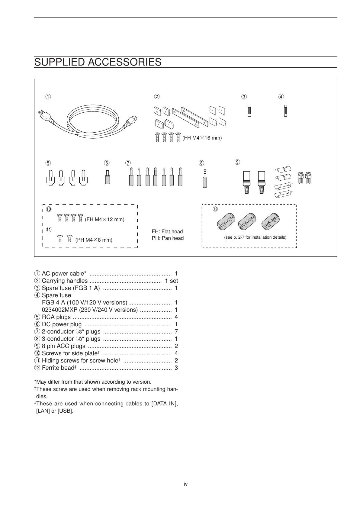
SUPPLIED ACCESSORIES
q
o
!0
!1
tyui
e
w
r
(FH M4×16 mm)
(FH M4×12 mm)
(PH M4×8 mm)
PH: Pan head
FH: Flat head
!2
(see p. 2-7 for installation details)
q AC power cable* ................................................. 1
w Carrying handles ........................................... 1 set
e Spare fuse (FGB 1 A) ......................................... 1
r Spare fuse
FGB 4 A (100 V/120 V versions) .......................... 1
0234002MXP (230 V/240 V versions)
................... 1
t RCA plugs ........................................................... 4
y DC power plug .................................................... 1
u 2-conductor
1
⁄8″ plugs ......................................... 7
i 3-conductor 1⁄8″ plugs ......................................... 1
o 8 pin ACC plugs .................................................. 2
!0 Screws for side plate
†
.......................................... 4
!1 Hiding screws for screw hole† ............................. 2
!2 F errite bead‡ ....................................................... 3
*May differ from that shown according to version.
†
These screw are used when removing rack mounting han-
dles.
‡
These are used when connecting cables to [DATA IN],
[LAN] or [USB].
iv

TABLE OF CONTENTS
Section 1 PANEL DESCRIPTION
Section 2 INSTALLATION AND CONNECTIONS
■ Front panel ........................................................................................ 1-2
■ Rear panel ...................................................................................... 1-10
■ LCD display .................................................................................... 1-12
■ Screen menu arrangement ............................................................. 1-14
■ Unpacking ......................................................................................... 2-2
■ Selecting a location .......................................................................... 2-2
■ Grounding ......................................................................................... 2-2
■ Antenna connection .......................................................................... 2-3
■ TV jumper cable connection (except for USA versions) ................... 2-4
■ Carrying handle attachment ............................................................. 2-4
■ Rack mounting handle detachment .................................................. 2-4
■ Required connections ....................................................................... 2-5
D Rear panel .................................................................................... 2-5
■ Advanced connections ..................................................................... 2-6
D Front panel .................................................................................... 2-6
D Rear panel—1 .............................................................................. 2-6
D Rear panel—2 .............................................................................. 2-7
■ Tape recorder connections ............................................................... 2-8
D Recording from the front panel or rear panel ............................... 2-8
D Separately recording audio and frequency .................................. 2-9
■ Monitor display connection ............................................................. 2-10
■ Transceive function ......................................................................... 2-10
■ FSK and AFSK (SSTV) connections .............................................. 2-11
■ Accessory connector information ................................................... 2-12
Section 3 BASIC OPERATIONS
■ When first applying power (CPU resetting) ...................................... 3-2
■ Initial settings .................................................................................... 3-2
■ Selecting VFO mode ........................................................................ 3-3
■ Selecting memory mode ................................................................... 3-3
■ Frequency setting ............................................................................. 3-4
D Direct frequency entry with the keypad ........................................ 3-4
D Tuning with the main dial .............................................................. 3-5
D Selecting a tuning step ................................................................. 3-5
D Auto tuning step function .............................................................. 3-6
1
D
⁄4 tuning step function ................................................................. 3-6
■ Operating mode selection ................................................................ 3-7
■ Volume setting .................................................................................. 3-8
■ RF gain adjustment .......................................................................... 3-8
■ Squelch level adjustment .................................................................. 3-8
■ Audio tone adjustment ...................................................................... 3-9
D Treble level adjustment ................................................................. 3-9
D Bass level adjustment ................................................................... 3-9
■ Meter indication selection ............................................................... 3-10
D Meter type selection ................................................................... 3-10
Section 4 RECEIVE MODES
■ Operating FM .................................................................................... 4-2
D Convenient functions for FM ..........................................................4-2
■ Duplex operation ............................................................................... 4-3
D Offset frequency setting ................................................................4-3
v
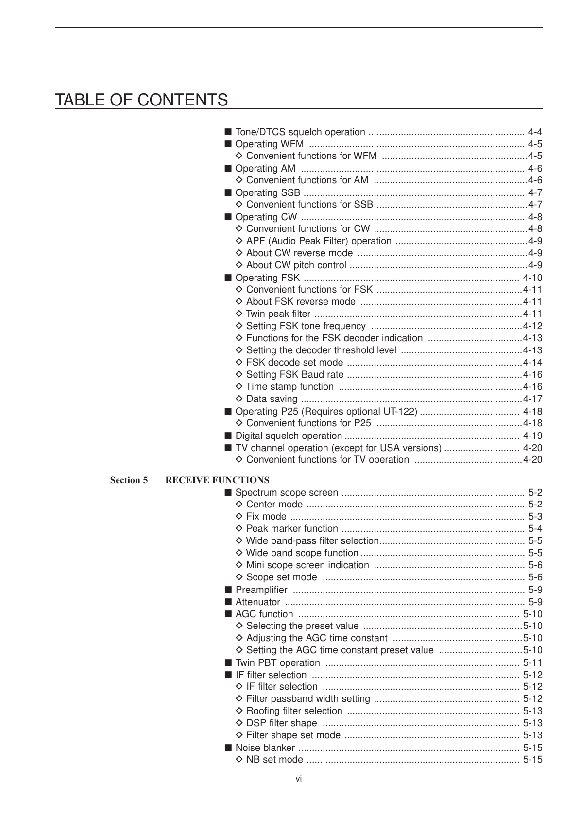
TABLE OF CONTENTS
■ Tone/DTCS squelch operation .......................................................... 4-4
■ Operating WFM ................................................................................ 4-5
D Convenient functions for WFM ......................................................4-5
■ Operating AM ................................................................................... 4-6
D Convenient functions for AM .........................................................4-6
■ Operating SSB .................................................................................. 4-7
D Convenient functions for SSB ........................................................4-7
■ Operating CW ................................................................................... 4-8
D Convenient functions for CW .........................................................4-8
D APF (Audio Peak Filter) operation .................................................4-9
D About CW reverse mode ...............................................................4-9
D About CW pitch control ..................................................................4-9
■ Operating FSK ................................................................................ 4-10
D Convenient functions for FSK ......................................................4-11
D About FSK reverse mode ............................................................4-11
D Twin peak filter .............................................................................4-11
D Setting FSK tone frequency ........................................................4-12
D Functions for the FSK decoder indication ...................................4-13
D Setting the decoder threshold level .............................................4-13
D FSK decode set mode .................................................................4-14
D Setting FSK Baud rate .................................................................4-16
D Time stamp function ....................................................................4-16
D Data saving ..................................................................................4-17
■ Operating P25 (Requires optional UT-122) ..................................... 4-18
D Convenient functions for P25 ......................................................4-18
■ Digital squelch operation ................................................................. 4-19
■ TV channel operation (except for USA versions) ............................ 4-20
D Convenient functions for TV operation ........................................4-20
Section 5 RECEIVE FUNCTIONS
■ Spectrum scope screen .................................................................... 5-2
D Center mode ................................................................................. 5-2
D Fix mode ....................................................................................... 5-3
D Peak marker function .................................................................... 5-4
D Wide band-pass filter selection ...................................................... 5-5
D Wide band scope function ............................................................. 5-5
D Mini scope screen indication ........................................................ 5-6
D Scope set mode ........................................................................... 5-6
■ Preamplifier ...................................................................................... 5-9
■ Attenuator ......................................................................................... 5-9
■ AGC function .................................................................................. 5-10
D Selecting the preset value ...........................................................5-10
D Adjusting the AGC time constant ................................................5-10
D Setting the AGC time constant preset value ...............................5-10
■ Twin PBT operation ........................................................................ 5-11
■ IF filter selection ............................................................................. 5-12
D IF filter selection ......................................................................... 5-12
D Filter passband width setting ...................................................... 5-12
D Roofing filter selection ................................................................ 5-13
D DSP filter shape ......................................................................... 5-13
D Filter shape set mode ................................................................. 5-13
■ Noise blanker .................................................................................. 5-15
D NB set mode ............................................................................... 5-15
vi

TABLE OF CONTENTS
Section 6 VOICE RECORDER FUNCTIONS
Section 7 MEMORY OPERATION
■ Noise reduction ............................................................................... 5-16
■ Notch function ................................................................................. 5-16
■ Autotune function ............................................................................ 5-17
■ AFC function ................................................................................... 5-17
■ About digital voice recorder .............................................................. 6-2
■ Recording a received audio ............................................................... 6-3
D Regular recording ......................................................................... 6-3
■ Playing the recorded audio ............................................................... 6-4
D Regular playing ............................................................................. 6-4
■ Erasing the recorded contents ......................................................... 6-4
■ Selecting the CF memory card or USB-Memory ............................. 6-4
■ Short recording ................................................................................. 6-5
D Recording ..................................................................................... 6-5
D Playing back ................................................................................. 6-5
■ Voice set mode ................................................................................. 6-6
■ Memory channels ............................................................................. 7-2
■ Memory channel selection ................................................................ 7-3
D Using the [M-CH]/[BANK] selectors .............................................. 7-3
D Using the keypad .......................................................................... 7-3
■ Memory channel programming ......................................................... 7-4
D Programming in VFO mode .......................................................... 7-4
D Programming in memory mode .................................................... 7-4
■ Frequency transferring ...................................................................... 7-5
D Transferring in VFO mode ............................................................. 7-5
D Transferring in memory mode ....................................................... 7-5
■ Memory names ................................................................................. 7-6
D Editing (programming) memory names ........................................ 7-6
■ Memory clearing ............................................................................... 7-6
■ Memory list screen ........................................................................... 7-7
D Selecting a memory channel using the memory list screen ........ 7-7
D Confirming programmed memory channels ................................. 7-7
D Memory bank set .......................................................................... 7-8
D Editing memory channel ............................................................... 7-9
Section 8 SCANS
■ Scan types ........................................................................................ 8-2
■ Preparation ....................................................................................... 8-3
■ Voice squelch control function .......................................................... 8-3
■ Scan set mode ................................................................................. 8-4
■ Priority scan ....................................................................................... 8-5
D Setting .......................................................................................... 8-5
D Priority scan operation .................................................................. 8-5
■ Programmed scan ............................................................................ 8-6
D Setting .......................................................................................... 8-6
D Program scan operation ............................................................... 8-7
■ ∂F scan ............................................................................................ 8-8
D Setting .......................................................................................... 8-8
D ∂F scan operation ........................................................................ 8-8
■ Fine programmed scan/fine ∂F scan operation ................................ 8-9
■ Auto memory write scan operation .................................................. 8-10
vii

TABLE OF CONTENTS
Section 9 OTHER FUNCTIONS
■ Memory scan .................................................................................. 8-11
D Setting ........................................................................................ 8-11
D Memory scan operation .............................................................. 8-11
D Programming the select memory scan setting ........................... 8-12
D Select memory scan operation ................................................... 8-13
D Mode select memory scan operation ......................................... 8-14
■ Skip scan ........................................................................................ 8-15
D Specifying skip channels ............................................................ 8-15
D Programming skip frequencies (for programming scan) ............ 8-15
D Skip scan setting ........................................................................ 8-15
■ Tone scan ....................................................................................... 8-16
■ Scan resume condition .................................................................... 8-17
■ Scan speed ...................................................................................... 8-18
■ Scan delay ....................................................................................... 8-18
■ Voice synthesizer operation .............................................................. 9-2
■ Lock function .................................................................................... 9-2
D Dial lock function ........................................................................... 9-2
D Panel lock function ......................................................................... 9-2
■ Dial click function .............................................................................. 9-3
■ Antenna selection ............................................................................. 9-3
Section 10 CLOCK AND TIMERS
■ Time set mode ................................................................................ 10-2
■ Daily timer setting ........................................................................... 10-3
■ Setting sleep timer .......................................................................... 10-4
■ Timer operation .............................................................................. 10-4
Section 11 SET MODE
■ Set mode description ...................................................................... 11-2
D Set mode operation .................................................................... 11-2
D Screen arrangement ................................................................... 11-3
■ Level set mode ............................................................................... 11-4
■ ACC set mode ................................................................................ 11-7
■ Display set mode ............................................................................ 11-8
■ Others set mode ........................................................................... 11-10
■ CF card/USB-Memory set menu .................................................. 11-16
D CF/USB-Memory set screen arrangement ............................... 11-16
D Load option set mode ............................................................... 11-17
■ File saving .................................................................................... 11-18
■ File loading ................................................................................... 11-19
■ Changing the file name ................................................................ 11-20
■ File copying .................................................................................. 11-21
■ Deleting a file ................................................................................ 11-22
■ Unmount an USB-Memory ........................................................... 11-22
■ Formatting the CF card or USB-Memory ...................................... 11-23
■ Display set (Video) mode ............................................................. 11-24
■ LCD set mode .............................................................................. 11-26
Section 12 MAINTENANCE
■ Troubleshooting .............................................................................. 12-2
D Receiver power ........................................................................... 12-2
D Receiving .................................................................................... 12-2
viii

TABLE OF CONTENTS
Section 13 CONTROL COMMAND
D Scanning ..................................................................................... 12-3
D Display ........................................................................................ 12-3
D Voice recorder ............................................................................. 12-3
D Format memory media ............................................................... 12-3
■ Screen type selection ..................................................................... 12-4
■ Main dial brake adjustment ............................................................ 12-4
■ Frequency calibration (approximate) .............................................. 12-5
■ Opening the receiver’s case ........................................................... 12-6
■ Opening the shield case ................................................................. 12-6
■ UT-122 installation .......................................................................... 12-7
■ Clock backup battery replacement ................................................. 12-7
■ Fuse replacement ........................................................................... 12-8
D AC power input fuse ................................................................... 12-8
D DC output fuse ........................................................................... 12-8
■ Resetting the CPU .......................................................................... 12-9
■ Screen Saver Function ................................................................... 12-9
■ Remote interface (CI-V) information ............................................... 13-2
D CI-V connection example ........................................................... 13-2
D Data format ................................................................................. 13-2
D Command table .......................................................................... 13-3
D To send/read memory contents ................................................ 13-10
D Codes for memory name, bank name, opening message,
and clock 2 name contents ....................................................... 13-10
D Offset frequency setting ............................................................ 13-10
D Tone squelch frequency setting ................................................ 13-10
D DTCS squelch code setting ...................................................... 13-10
D NAC squelch code setting ........................................................ 13-11
D Selective squelch code settings ............................................... 13-11
D Color setting ............................................................................ 13-11
D Data mode with filter width setting ........................................... 13-11
Section 14 SPECIFICATIONS AND OPTIONS
■ Specifications ................................................................................. 14-2
D General ....................................................................................... 14-2
D Receiver ...................................................................................... 14-3
■ Options ........................................................................................... 14-4
Section 15 UPDATING THE FIRMWARE
■ General ........................................................................................... 15-2
■ Caution ........................................................................................... 15-2
■ Preparation ..................................................................................... 15-3
D Firmware and firm utility ............................................................. 15-3
D File downloading ....................................................................... 15-3
■ Firmware update— CF memory card ............................................. 15-4
■ Firmware update— PC ................................................................... 15-6
D Connections ................................................................................ 15-6
D IP address setting ....................................................................... 15-7
D Updating from the PC ................................................................. 15-8
ix

PANEL DESCRIPTION Section 1
■ Front panel ........................................................................................ 1-2
■ Rear panel ...................................................................................... 1-10
■ LCD display .................................................................................... 1-12
■ Screen menu arrangement ............................................................. 1-14
1-1

1
i
!0
q
w
e
r
t
y
u
o!1!2
!3
!4 !5
PANEL DESCRIPTION
■ Front panel
q POWER SWITCH [POWER] (p. 3-2)
Turn the internal power supply ON before turning
the unit ON from the front panel. The internal power
supply switch is located on the rear panel. (p. 3-2)
➥ Push to turn the receiver power ON.
•The[POWER]indicatorabovethisswitchlightsgreen
when powered ON.
➥ Push for 1 sec. to turn the receiver power OFF.
•The[POWER]indicatorlightsorangewhenthere-
ceiver is OFF when the internal power supply is
switched ON.
w REMOTE CONTROL SWITCH [LOCAL]
Push to cancel remote control operation from a PC
via a CI-V data.
•The[REMOTE]indicatorlightsorangewhileinremote
control operation.
•Whenthe[REMOTE]indicatorlightsorange,alldials,
keys or switches other than this switch are disabled.
e PANEL LOCK SWITCH [PANEL LOCK] (p. 9-2)
➥
Push to turn the panel lock function ON or OFF.
The panel lock function locks all dials (depends on
set mode setting on p. 11-10), keys and switches
other than [POWER] and [PANEL LOCK].
•The[PANELLOCK]indicatorabovethisswitchlights
green when the panel lock is in use.
•Thediallockfunctionisalsoavailable.
➥ Push and hold for 1 sec. to turn the panel lock
with display sleep function ON.
•Pushing[PANELLOCK]turnsthisfunctionOFF.
•The[PANELLOCK]indicatorabovethisswitchlights
green and the display turns OFF when the sleep
function is in use.
r TIMER SWITCH [TIMER] (p. 10-3)
➥ Turns the sleep or daily timer function ON or
OFF.
•The[TIMER]indicatorabovethisswitchlightsgreen
when the timer is in use.
➥ Enters timer set mode when pushed and held for
1 sec.
t RECORDER REMOTE JACK [REC REMOTE]
Controls the operation of a tape recorder for record-
ing. Connects to the REMOTE jack on a tape re-
corder.
y RECORDER JACK [REC OUT]
Outputs an audio signal. Connect to the AUX or
LINE IN jack on a tape recorder.
u HEADPHONE JACK [PHONES]
Accepts standard 3.5 (d) mm (
phones.
•Outputpower:40mWwithan8Ω load.
•Whenheadphonesareconnected,theinternalspeaker
or connected external speaker does not function.
1
⁄8) stereo head-
1-2

PANEL DESCRIPTION
Deep
Deep
S-meter
squelch
Noise squelch
Squelch
is open.
Squelch
threshold
Shallow
Shallow
Low cutHigh cut Center
–+
(PBT1) (PBT2)
Slow
Fast
AN
MN1
MN2
Higher
frequency
NOTCH1
NOTCH2
Lower
frequency
1
i SQUELCH CONTROL [SQUELCH] (p. 3-8)
Adjusts the squelch threshold level. The squelch
disables output from the speaker (closed condition)
when no signal is received.
•ThesquelchcontrolisparticularlyeffectiveforFMor
AM. It is also available for other modes.
•11to12o’clockpositionisrecommendedforanysetting
of the [SQL] control.
o PASSBAND TUNING CONTROLS [TWIN PBT]
(p. 5-11)
Adjusts the receiver’s IF filter “passband width” via
the DSP.
•Passbandwidthandshiftfrequencyareshownonthe
multifunction display.
•Pushandhold[PBTCLEAR]for1sec.toclearthePBT
settings.
•ThePBTisadjustablein50HzstepsintheSSB/CW/
FSK modes, and 200 Hz in the AM mode. In this time,
the shift value changes in 25 Hz steps in the SSB/CW/
FSK modes, and 100 Hz in the AM mode.
•ThesecontrolsfunctionasanIFshiftcontrol.
!1 AGC CONTROL [AGC] (p. 5-10)
Adjusts the continuously-variable AGC circuit time
constant.
•Touse[AGC]control,pushtheappropriateband’s
[AGC VR/OFF] ([AGC VR] indicator lights green).
!2 AGC SWITCH [AGC VR/OFF] (p. 5-10)
➥ Push to toggle [AGC] control usage ON or OFF.
•Use[AGC]controltosettheAGCtimeconstantwhen
switched ON.
•The[AGCVR]indicatorabovethisswitchlightsgreen
when the control is ON.
➥ Turns the AGC function OFF when pushed and
held for 1 sec.
!3 AUTO NOTCH SWITCH [ANF] (p. 5-16)
➥ Turns the auto notch function ON or OFF when
pushed in SSB, AM, FM and WFM mode.
•“
” appears when auto notch is in use.
!4 MANUAL NOTCH SWITCHES [NOTCH1]/
[NOTCH2] (p. 5-16)
➥ Turns the manual notch function ON or OFF
when pushed in SSB, CW, AM and FSK mode.
•“
use.
” or “
” appear when manual notch is in
➥ Switches the manual notch characteristics be-
tween wide, middle and narrow when pushed
and held for 1 sec.
✔ What is the notch function?
The notch function eliminates unwanted CW or AM carrier
tones while preserving the desired voice signal. The DSP cir-
cuit automatically adjusts the notch frequency to effectively
eliminate unwanted tones.
!5 MANUAL NOTCH FILTER CONTROLS
[NOTCH1]/[NOTCH2] (p. 5-16)
Varies the “notch” frequency of the manual notch
filter to reject an interfering signal while the manual
notch function is ON.
•Notchfiltercenterfrequency:
SSB : –1060 Hz to 4040 Hz
✔ What is the PBT control?
The PBT function electronically modifies the IF passband
width to reject interference. This receiver uses the DSP cir-
cuit for the PBT function.
CW : CW pitch freq. + 2540 Hz to CW pitch freq.
–2540 Hz
AM : –5100 Hz to 5100 Hz
!0 PBT CLEAR SWITCH [PBT CLEAR] (p. 5-11)
Push and hold for 1 sec. to clear the PBT settings.
•The[PBTCLEAR]indicatorabovethisswitchlights
when PBT is in use.
1-3

NB1
NB2
APF
TPF
Increases
Decreases
Deep
Shallow
Sensitivity
increases
Sensitivity
decreases
1
!9
!7
!6
@0
!8
@3
@4
@1
@2
@5
PANEL DESCRIPTION
■ Front panel (continued)
!6 NOISE REDUCTION SWITCH [NR] (p. 5-16)
Push to switch the DSP noise reduction ON or
OFF.
•The[NR]indicatorabovethisswitchlightsgreenwhen
the function is activated.
!7 NOISE BLANKER SWITCH [NB] (p. 5-15)
➥ Selects from noise blanker 1, 2, or OFF when
pushed. The noise blanker reduces pulse-type
noise such as that generated by automobile ig-
nition systems. This function cannot be used for
FM, WFM, P25 modes or non-pulse-type noise.
•The[NB]indicatorabovethisswitchlightsgreenand
“
” or “
function is activated.
➥ Enters blank-width set mode when pushed and
held for 1 sec.
!8 AUDIO PEAK FILTER/TWIN PEAK FILTER
SWITCH [APF/TPF]
➥ Push to turn the audio peak filter ON or OFF dur-
ing CW mode operation. (p. 4-9)
➥ Push to turn the twin peak filter ON or OFF dur-
ing FSK mode operation. (p. 4-11)
•“
•“
➥ During CW mode operation, push and hold for
1 sec. to select the APF passband width from 80,
160 and 320 Hz. (p. 4-9)
” appears when audio peak filter is in use.
” appears when twin peak filter is in use.
” appears on the display when the
!9 NOISE REDUCTION LEVEL CONTROL
[NR LEVEL] (outer control; p. 5-16)
Adjusts the DSP noise reduction level when noise
reduction is in use. Set for maximum readability.
•Tousethiscontrol,noisereductionmustbeON.
@0 NOISE BLANKER CONTROL [NB LEVEL]
(inner control; p. 5-15)
Adjust the noise blanker threshold level.
•Tousethiscontrol,eithernoiseblankermustbeON.
@1 RF GAIN CONTROL [RF] (outer control; p. 3-8)
Adjusts the RF gain level.
While rotating the RF gain control, you may hear
noise. This comes from the DSP unit and does
not indicate a malfunction.
1-4
Audio output
increases
Audio output
decreases
Bass level
increases
Bass level
decreases
Treble level
increases
Treble level
decreases
PANEL DESCRIPTION
1
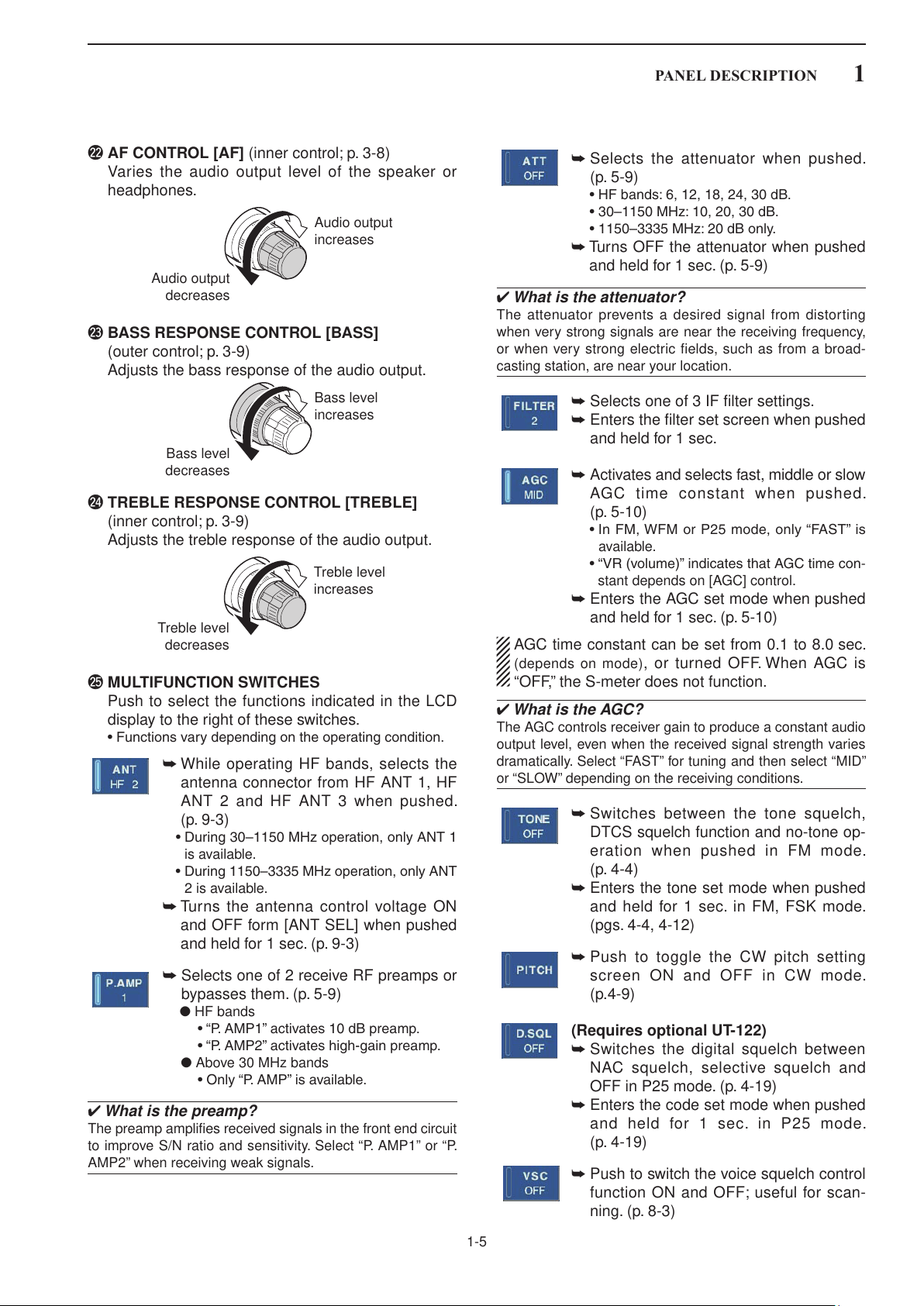
@2 AF CONTROL [AF] (inner control; p. 3-8)
Varies the audio output level of the speaker or
headphones.
@3 BASS RESPONSE CONTROL [BASS]
(outer control; p. 3-9)
Adjusts the bass response of the audio output.
@4 TREBLE RESPONSE CONTROL [TREBLE]
(inner control; p. 3-9)
Adjusts the treble response of the audio output.
➥ Selects the attenuator when pushed.
(p. 5-9)
•HFbands:6,12,18,24,30dB.
•30–1150MHz:10,20,30dB.
•1150–3335MHz:20dBonly.
➥ Turns OFF the attenuator when pushed
and held for 1 sec. (p. 5-9)
✔ What is the attenuator?
The attenuator prevents a desired signal from distor ting
when very strong signals are near the receiving frequency,
or when very strong electric fields, such as from a broad-
casting station, are near your location.
➥ Selects one of 3 IF filter settings.
➥ Enters the filter set screen when pushed
and held for 1 sec.
➥ Activates and selects fast, middle or slow
AGC time constant when pushed.
(p. 5-10)
•InFM,WFMorP25mode,only“FAST”is
available.
•“VR(volume)”indicatesthatAGCtimecon-
stant depends on [AGC] control.
➥ Enters the AGC set mode when pushed
and held for 1 sec. (p. 5-10)
@5 MULTIFUNCTION SWITCHES
Push to select the functions indicated in the LCD
display to the right of these switches.
•Functionsvarydependingontheoperatingcondition.
➥ While operating HF bands, selects the
antenna connector from HF ANT 1, HF
ANT 2 and HF ANT 3 when pushed.
(p. 9-3)
•During30–1150MHzoperation,onlyANT1
is available.
•During1150–3335MHzoperation,onlyANT
2 is available.
➥ Turns the antenna control voltage ON
and OFF form [ANT SEL] when pushed
and held for 1 sec. (p. 9-3)
➥ Selects one of 2 receive RF preamps or
bypasses them. (p. 5-9)
●HF bands
•“P.AMP1”activates10dBpreamp.
•“P.AMP2”activateshigh-gainpreamp.
● Above 30 MHz bands
•Only“P.AMP”isavailable.
✔ What is the preamp?
The preamp amplifies received signals in the front end circuit
to improve S/N ratio and sensitivity. Select “P. AMP1” or “P.
AMP2” when receiving weak signals.
AGC time constant can be set from 0.1 to 8.0 sec.
(depends on mode), or turned OFF. When AGC is
“OFF,” the S-meter does not function.
✔ What is the AGC?
The AGC controls receiver gain to produce a constant audio
output level, even when the received signal strength varies
dramatically. Select “FAST” for tuning and then select “MID”
or “SLOW” depending on the receiving conditions.
➥ Switches between the tone squelch,
DTCS squelch function and no-tone op-
eration when pushed in FM mode.
(p. 4-4)
➥ Enters the tone set mode when pushed
and held for 1 sec. in FM, FSK mode.
(pgs. 4-4, 4-12)
➥ Push to toggle the CW pitch setting
screen ON and OFF in CW mode.
(p.4-9)
(Requires optional UT-122)
➥ Switches the digital squelch between
NAC squelch, selective squelch and
OFF in P25 mode. (p. 4-19)
➥ Enters the code set mode when pushed
and held for 1 sec. in P25 mode.
(p. 4-19)
➥ Push to switch the voice squelch control
function ON and OFF; useful for scan-
ning. (p. 8-3)
1-5

1
$3
@8 #3 #8#0@9 #5 #6 #7 #9 $0#4
@7@6 #1 #2
$1 $2 $4
PANEL DESCRIPTION
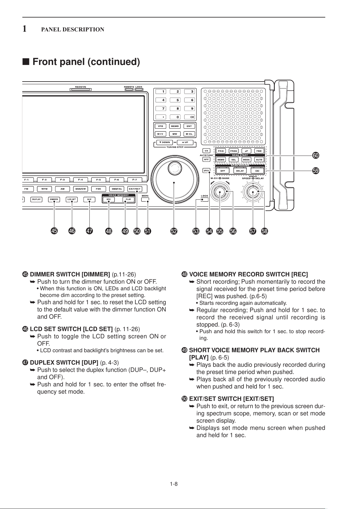
■ Front panel (continued)
@6 LCD FUNCTION DISPLAY (p. 1-10)
Shows the operating frequency, function switch
menus, spectrum scope screen, memory channel
screen, set mode settings, etc.
@7 RECEIVE INDICATOR [RECEIVE]
Lights green while receiving a signal and when the
squelch is open.
@8 TUNING STEP SWITCHES [▲UP]/[▼DOWM]
(p. 3-5)
➥ Select the tuning step for the main dial. Push
[▲UP] to select a larger tuning step; push
[▼DOWN] to select a smaller tuning step.
•1Hz,10Hz,100Hz,1kHz,2.5kHz,5kHz,6.25
kHz, 9 kHz, 10 kHz, 12.5 kHz, 20 kHz, 25 kHz, 100
kHz and 1 MHz are selectable.
•Programmabletuningstepscanbesetbetween0.1
and 999.9 kHz in 0.1 kHz steps.
➠ To set programmable tuning steps, enter the de-
➥ Push and hold [▲UP] (or [▼DOWN]) for 1 sec. to
enter the tuning step select screen.
•Unwantedtuningstepforeachoperatingmodecan
be skipped in the tuning step select.
sired steps via the keypad, then push [YUP] or
[ZDOWN].
@9 MEMORY TRANSFER SWITCH [M≈V] (p. 7-5)
Transfers the memory contents to VFO when
pushed and held for 1 sec.
•ThisfunctionisavailablebothinVFOandmemory
modes.
#0 MEMORY SWITCH [MEMO] (p.7-3)
➥ Selects the memory mode when pushed.
•Afterpushingonetothreedigit(0to999),pushing
the switch selects a memory channel.
➥ Memory bank limit function ON or OFF when
pushed and held for 1 sec.
#1 REMOTE CONTROL INDICATOR [REMOTE]
Lights yellow when a command is received from a
PC via CI-V data.
•Whenthisindicatorlightsyellow,alldials,keysor
switches other than [LOCAL] are disabled.
•ThisindicatorgoesOFF,when[LOCAL]ispushed.
#2 DIAL LOCK INDICATOR [LOCK] (p. 9-2)
Lights orange when the dial lock function is acti-
vated.
1-6

1
⁄
4
AFC
AUTO TUNE
WF
M
SSB/CW
FSK
DIGITAL
PANEL DESCRIPTION
1
#3 VFO SWITCH [VFO]
Selects the VFO mode when pushed. (p. 3-3)
•Afterpushingadigitswitch(0to9),pushthisswitch
selects a VFO mode (VFO-0 to VFO-9).
#4 KEYPAD (pgs. 3-3, 3-4, 7-3)
Enters a frequency or memory channel. Pushing
[ENT], [VFO] or [MEMO] ends keypad input.
•e.g.toenter14.195MHz,push[1][4][•][1][9][5]
[ENT].
#5 ENTER SWITCH [ENT]
Enters input frequency. (pgs. 3-4)
#6 MEMORY WRITE SWITCH [MW] (p. 7-4)
Stores the selected readout frequency and operat-
ing mode into the displayed memory channel when
pushed and held for 1 sec.
•ThisfunctionisavailablebothinVFOandmemory
modes.
#7 MEMORY CLEAR SWITCH [M-CL] (p. 7-7)
Push and hold to clear the contents of displayed
memory channel.
#8 SPEAKER
Outputs audio signals.
#9 1/4-SPEED TUNING SWITCH [1/4]
➥ Push to turn the
1
⁄4-speed tuning function ON or
OFF in CW and FSK modes. (p. 3-6)
•“
•
” appears when 1⁄4 function is in use.
1
⁄4 function sets dial rotation to 1⁄4 of normal speed
for fine tuning.
➥ Push and hold to turn the dial click function ON
or OFF. (p. 9-3)
$0 AFC/AUTOMATIC TUNING SWITCH
[AFC•AUTOTUNE]
➥ Turns the AFC function ON or OFF in FM or
WFM modes.
•“
” appears when AFC function is in use.
➥ Turns the automatic tuning function ON or OFF
in AM, SSB and CW modes.
•“
vate.
” blinks when autotune function is acti-
IMPORTANT!
When receiving a weak signal, or receiving a
signal with interference, the automatic tuning
function may tune the receiver to an unde-
sired signal.
$1 LCD FUNCTION SWITCHES [F-1]–[F-7]
Push to select the function indicated in the LCD dis-
play above these switches.
•Functionsvarydependingontheoperatingcondition.
$2 MINI SPECTRUM SCOPE SWITCH [M.SCOPE]
(p. 5-6)
➥ Turns the mini spectrum scope screen ON or
OFF.
•Theminispectrumscopescreencanbedisplayed
with another screen, such as memory or set mode
screen, simultaneously.
➥ Turns the spectrum scope screen ON when
pushed and held for 1 sec.
$3 MODE SWITCHES
Selects the desired mode. (p. 3-7)
•Announcesselectedmodeviathespeechsynthesizer.
(p. 11-11)
➥ Selects FM mode.
➥ Selects WFM mode.
➥
Selects AM and S-AM modes alternately.
➥ Switches S-AM(D), S-AM(U) and S-
AM(L) mode when pushed and held for
1 sec. in S-AM mode.
➥ Switches between SSB and CW mode.
➥ Switches between LSB and USB mode
when pushed and held for 1 sec. in SSB
mode.
➥ Switches between CW and CW-R (CW
reverse)
mode when pushed and held for
1 sec. in CW mode.
➥ Selects FSK and FSK-R (FSK reverse)
modes alternately.
➥ Selects Digital (P25) mode. (Requires
optional UT-122.)
$4 DISPLAY SWITCH [DISPLAY]
➥ Push to toggle the external input screen between
mini video screen, full video screen, or OFF.
•Ifnosignalinputsfrom[VIDEOIN],blackscreenap-
pears.
➥ Enter the display set mode menu screen when
pushed and held for 1 sec.
1-7
1
$8
$5 $6 $7
$9 %1
%9
^0
%2 %4 %5 %6%3 %7 %8
%0
PANEL DESCRIPTION
■ Front panel (continued)
$5 DIMMER SWITCH [DIMMER] (p.11-26)
➥ Push to turn the dimmer function ON or OFF.
•WhenthisfunctionisON,LEDsandLCDbacklight
become dim according to the preset setting.
➥ Push and hold for 1 sec. to reset the LCD setting
to the default value with the dimmer function ON
and OFF.
$6 LCD SET SWITCH [LCD SET] (p. 11-26)
➥ Push to toggle the LCD setting screen ON or
OFF.
•LCDcontrastandbacklight’sbrightnesscanbeset.
$7 DUPLEX SWITCH [DUP] (p. 4-3)
➥ Push to select the duplex function (DUP–, DUP+
and OFF).
➥ Push and hold for 1 sec. to enter the offset fre-
quency set mode.
$8 VOICE MEMORY RECORD SWITCH [REC]
➥ Short recording; Push momentarily to record the
signal received for the preset time period before
[REC] was pushed. (p.6-5)
•Startsrecordingagainautomatically.
➥ Regular recording; Push and hold for 1 sec. to
record the received signal until recording is
stopped. (p. 6-3)
•Pushandholdthisswitchfor1sec.tostoprecord-
ing.
$9 SHORT VOICE MEMORY PLAY BACK SWITCH
[PLAY] (p. 6-5)
➥ Plays back the audio previously recorded during
the preset time period when pushed.
➥ Plays back all of the previously recorded audio
when pushed and held for 1 sec.
%0 EXIT/SET SWITCH [EXIT/SET]
➥ Push to exit, or return to the previous screen dur-
ing spectrum scope, memory, scan or set mode
screen display.
➥ Displays set mode menu screen when pushed
and held for 1 sec.
1-8
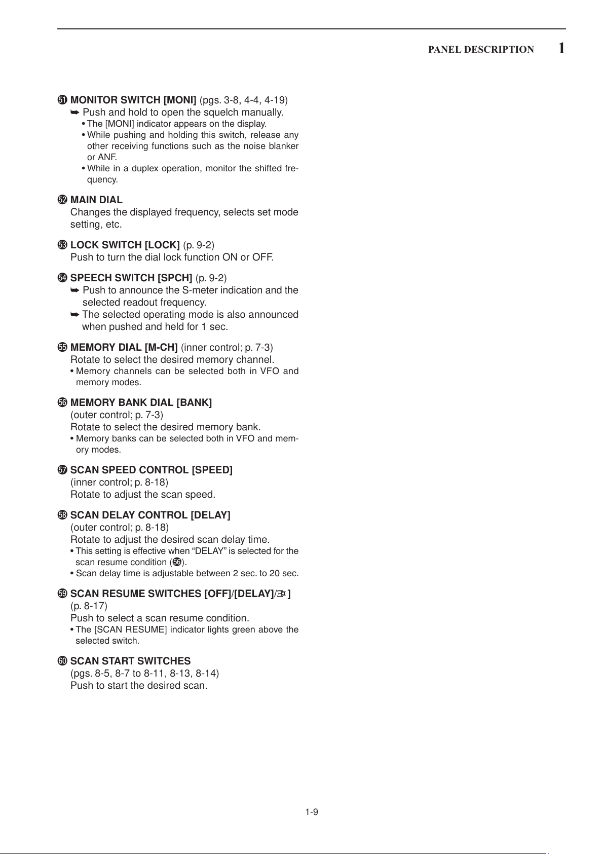
%1 MONITOR SWITCH [MONI] (pgs. 3-8, 4-4, 4-19)
➥ Push and hold to open the squelch manually.
•The[MONI]indicatorappearsonthedisplay.
•Whilepushingandholdingthisswitch,releaseany
other receiving functions such as the noise blanker
or ANF.
•Whileinaduplexoperation,monitortheshiftedfre-
quency.
%2 MAIN DIAL
Changes the displayed frequency, selects set mode
setting, etc.
%3 LOCK SWITCH [LOCK] (p. 9-2)
Push to turn the dial lock function ON or OFF.
%4 SPEECH SWITCH [SPCH] (p. 9-2)
➥ Push to announce the S-meter indication and the
selected readout frequency.
➥ The selected operating mode is also announced
when pushed and held for 1 sec.
PANEL DESCRIPTION
1
%5 MEMORY DIAL [M-CH] (inner control; p. 7-3)
Rotate to select the desired memory channel.
•MemorychannelscanbeselectedbothinVFOand
memory modes.
%6 MEMORY BANK DIAL [BANK]
(outer control; p. 7-3)
Rotate to select the desired memory bank.
•MemorybankscanbeselectedbothinVFOandmem-
ory modes.
%7 SCAN SPEED CONTROL [SPEED]
(inner control; p. 8-18)
Rotate to adjust the scan speed.
%8 SCAN DELAY CONTROL [DELAY]
(outer control; p. 8-18)
Rotate to adjust the desired scan delay time.
•Thissettingiseffectivewhen“DELAY”isselectedforthe
scan resume condition (%6).
•Scandelaytimeisadjustablebetween2sec.to20sec.
%9 SCAN RESUME SWITCHES [OFF]/[DELAY]/[¤ ]
(p. 8-17)
Push to select a scan resume condition.
•The[SCANRESUME]indicatorlightsgreenabovethe
selected switch.
^0 SCAN START SWITCHES
(pgs. 8-5, 8-7 to 8-11, 8-13, 8-14)
Push to start the desired scan.
1-9

+
_
_
1
@9 @7 @3@4@5@6 !9 !8@0@1@2@8
qw er tyuio!0!1!2!3!4!5!6!7
PANEL DESCRIPTION
■ Rear panel
q EXTERNAL SPEAKER JACK [EXT-SP] (p. 2-6)
Connects an external speaker (4–8 Ω), if desired.
w DC OUTPUT JACK [DC OUTPUT 15V MAX 1A]
(p. 2-6)
Outputs regulated 15 V DC (approx.) for external
equipment. Connected in parallel with 13.8 V out-
puts of [ACC]. (max. 1 A total)
e ACCESSORY SOCKET [ACC] (p. 2-6)
Enables connection of external equipment such as
an automatic antenna selector, a TNC for data
communications, etc.
•Seep.2-12forsocketinformation.
r ANTENNA SELECTOR VOLTAGE OUTPUT
JACK [ANT SEL]
Outputs regulated 13.8 V DC (max. 100 mA) for
external preamplifier or antenna selector, etc.
t REFERENCE SIGNAL INPUT/OUTPUT
TERMINAL [REF I/O 10MHz–10dBm]
Inputs/outputs a 10 MHz reference signal.
y SPEECH OUTPUT JACK [SPEECH OUT] (p. 2-9)
Outputs an operating frequency, mode, S-meter in-
dication and time with a synthesized voice when
pushing [SPCH] or scan stopped.
•TurnONthe“RECSPCH”intheotherssetmodetoac-
tivate this jack when scan stopped. (p. 11-11)
•OutputlevelcanbeadjustedinACCsetmode.(p.11-7)
u LINE OUTPUT JACK [LINE OUT]
Audio output jack for tape recorder. The fixed audio
output level is set for a tape recorder AUX jack.
i RECORDER REMOTE JACK [REC REMOTE]
Controls the operation of a tape recorder for re-
cording. Connects to the REMOTE jack on a tape
recorder.
o DETECTOR OUTPUT JACK [DET OUT]
Outputs the detector output signal.
!0 VIDEO INPUT JACK [VIDEO IN]
Accepts video signals for display on the LCD moni-
tor when the [DISPLAY] switch is ON.
!1 VIDEO OUTPUT JACK [VIDEO OUT]
Outputs video signals when TV frequencies with
WFM mode are received. The NTSC M, PAL B/G,
PAL I, PAL D and SECAM K system can be ac-
cepted. (No signals come out for USA versions.)
!2 SPARE JACK [SPARE] (p. 2-3)
No connection.
!3 IF OUTPUT JACK [IF OUT] (p. 2-3)
Outputs a 10.7 MHz IF signal.
Output level is the same level as an antenna input
signal or below (when the AGC function is acti-
vated or attenuator is ON.)
!4 DC-DC POWER SOCKET [DC-DC IN] (p. 2-6)
Accepts a regulated 13.5 to 15 V DC input. This
socket does not accept voltage from a non-regu-
lated power source such as a vehicle’s battery.
1-10

PANEL DESCRIPTION
1
!5 FUSE HOLDER [FUSE] (p. 12-8)
Holds a 4 A fuse (100 V/120 V versions) or 2 A
fuse (230 V/240 V versions) for internal AC power
supply protection. Cuts off the AC input when
over-current occurs.
CAUTION: Always use the correct fuse for AC
input power. Using a fuse rated for a different
input power may damege your house electrical
system or the receiver.
!6 AC POWER SOCKET [AC] (p. 2-5)
Connects the supplied AC power cable to an AC
line-voltage receptacle.
!7 MAIN POWER SWITCH [I/O] (p. 3-2)
Turns the internal power supply ON or OFF.
!8 GROUND TERMINAL [GND] (p. 2-2)
Connect this terminal to a ground to prevent elec-
trical shocks, TVI, BCI and other problems.
!9 HF ANTENNA CONNECTOR 1 [HF ANT 1]
(p. 2-5)
Accepts a 50 Ω antenna for HF bands with a PL-
259 plug connector.
@6 EXTERNAL DISPLAY TERMINAL
[EXT-DISPLAY] (p. 2-10)
Connects to an external display monitor.
•Atleast800×600 pixel display is necessary.
@7 RS-232C TERMINAL [RS-232C] (p. 2-6)
Connects to a PC using a D-sub 9-pin RS-232C
cable.
Can be used for remote control of the IC-R9500
without the optional CT-17, or the FSK decoded
signal output. The [RS-232C] interface is wired as
a modem (DCE).
@8 CI-V REMOTE CONTROL JACK [REMOTE]
(p. 2-6)
➥ Connects a PC via the optional CT-17
C O N V E R T E R for external control of the receiver.
C I -V L E V E L
➥ Used for transceive operation with another Icom
CI-V transceiver or receiver.
@9 DATA SOCKET [DATA IN]
(pgs. 2-10, 2-12)
Outputs LCD monitor signals (NTSC system).
@0 HF ANTENNA CONNECTOR 2 [HF ANT 2]
(p. 2-5)
Accepts a 500 Ω antenna for HF band with an RCA
connector.
@1 USB CONNECTOR [USB]
Connects USB equipment such as a memory
media, hub or keyboard.
@2 S/P DIF OUTPUT TERMINAL [S/P DIF OUT]
(p. 2-7)
Connects external equipment that supports S/P
DIF output.
@3 HF ANTENNA CONNECTOR 3/ANTENNA CON-
NECTOR 1 [ANT 1/HF ANT 3] (p. 2-5)
Accepts a 50 Ω antenna with a Type-N connector.
Covers the HF bands and 30–1150 MHz frequency
range.
@4 ETHERNET CONNECTOR [LAN] (pgs. 2-7, 15-6)
Connects to a PC through a LAN (Local Area Net-
work).
@5 ANTENNA CONNECTOR 2 [ANT 2] (p. 2-5)
Accepts a 50 Ω antenna with a Type-N connector.
Covers the 1150–3335 MHz frequency range.
1-11

•S-meter
•dBµ meter
•dBµ (EMF) meter
•dBmmeter
•FM/WFMmodes•FSKmode
1
@3@4@6@8 @7@9 @5 @2
!0
@1
!3
!2
@0
!4
o
!1
r
w
u
y
!8
!7
!6
q
t
!5
!9
e
i
PANEL DESCRIPTION
■ LCD display
q RSSI (
Shows the received signal strength. Four meter
Received Signal Strength Indication
(p. 3-10)
types, S, dBµ, dBµ(EMF) and dBm meters are se-
lectable.
) METER
w CENTER METER
Shows that the received signal is tuned to its
center frequency for FM, WFM or FSK modes.
e MODE INDICATOR (p. 3-7)
Shows the selected receive mode.
r VFO/MEMORY INDICATOR (pgs. 3-3, 7-3)
Indicates the selected VFO number (VFO-0 to
VFO-9) or memory mode.
t IF FILTER INDICATOR (p. 5-12)
Shows the selected IF filter number.
y FREQUENCY READOUTS
Shows the operating frequency.
u
SELECT MEMORY CHANNEL INDICATOR (p. 8-12)
Indicates the displayed memory channel is set as
a select memory channel.
i MEMORY CHANNEL READOUTS
➥ Shows the selected memory channel contents
in VFO mode.
➥ Shows the VFO contents in memory mode.
1-12

PANEL DESCRIPTION
AUTO TUNE
TSQL
DTCS
NAC
SEL
NB1
NB2
CF
USB
AN
MN1
MN2
DUP–
DUP+
1
o MULTIFUNCTION SWITCH GUIDE
Indicates the function of the multifunction switches.
!0 LCD FUNCTION SWITCH GUIDE
Indicates the function of the LCD function switches
([F-1] – [F-7]).
!1 MULTIFUNCTION SCREEN
Shows the screens for the spectrum scope, voice
recorder, memory channel list, scan, FSK decoder,
IF filter selection or set modes, etc.
!2 TUNING STEP INDICATOR (p. 3-5)
Shows the selected tuning step.
!3 1/4 FUNCTION INDICATOR (p. 3-6)
Appears when the 1/4-speed tuning function is ac-
tivated in CW and FSK modes.
!4 AUTOMATIC TUNE INDICATOR (p. 5-17)
“
” blinks during automatic tuning. This
feature is active in AM, SSB and CW mode.
!5 MEMORY CHANNEL INDICATOR (p. 7-3)
Indicates the selected memory channel number.
!6 TUNING DIGIT INDICATOR (p. 3-5)
Shows the tuneable digit when rotating the main
dial.
!7 TONE/DTCS/NAC/SELECTIVE SQUELCH
INDICATOR
➥ “
” or “
” appears when the tone
squelch or DTCS squelch is set in FM mode.
(p. 4-4)
➥ “
” or “
” ap p ea rs wh en th e NAC
squelch or selective squelch is selected in P25
mode. (Requires optional UT-122.) (p.4-19)
!8 BANK INDICATOR (p. 7-3)
Appears when the bank limit function is in use and
indicates the selected bank number.
•BANK-0toBANK-9,BANK-A(AUTOMW),BANK-S
(SKIP) and BANK-P (SCAN EDGE) are selectable.
!9 NOISE BLANKER INDICATOR (p. 5-15)
“
” or “
” appea r s wh e n ei t h er n oise
blanker 1 or noise blanker 2 is ON. This function is
not available for FM, WFM or P25 mode.
@0 CF CARD/USB-MEMORY INDICATOR (p. 11-16)
➥ “
” appears when CF card is correctly con-
nected and blinks while CF card is active.
•ThisindicatorisnormallystayedON.
The IC-R9500 comes with 512MB CF card in-
stalled as an internal memory. If you would lik e
to replace or uninstall the internal memory (CF
card), ask your dealer for details.
➥ “
” appears when USB-Memory is con-
nected, and blinks while it is active.
@1 CLOCK READOUT (p. 10-2)
Shows the current time. Local and UTC time can
be indicated at the same time.
@2 NOISE REDUCTION INDICATOR (p. 5-16)
Appears when noise reduction function is in use.
@3 BANDPASS FILTER INDICATOR
Appears when the narrow filter (500 Hz or less) is
selected during CW or FSK operation.
@4 PASSBAND WIDTH INDICATOR (p. 5-11)
Graphically displays the passband width for twin
PBT operation and center frequency for IF shift op-
eration.
@5 AUDIO PEAK FILTER INDICATOR (p. 4-9)
Appears when the audio peak filter function is in use.
This function is available in CW mode
@6 SHIFT FREQUENCY INDICATOR (p. 5-11)
Shows the shift frequency of the IF filter.
@7 NOTCH FILTER INDICATOR (p. 5-16)
➥ “
” appears when the auto notch function is
in use. This function is available in FM, WFM,
AM and SSB modes.
➥ “
” or “
” appear
s when the manual
notch filter function is in use. This function is avail-
able in AM, SSB, CW and FSK mode.
@8 BAND WIDTH INDICATOR (p. 5-11)
Shows the passband width of the IF filter.
@9 DUPLEX INDICATOR (p. 4-3)
“
” or “
” appears when the negative duplex
or positive duplex operation is selected, respectively.
1-13

1
•Spectrumscopescreen(p. 5-2)
•Voicerecorderscreen(p. 6-3)
•FSKdecoderscreen(p. 4-14)
•Memorychannelscreen(p. 7-4)
•Scanscreen(p. 5-5)
•Setmodemenuscreen(p. 11-2)
PANEL DESCRIPTION
■ Screen menu arrangement
The following screens can be selected from the start
up screen. Choose the desired screen using the fol-
lowing chart.
Pushing [EXIT/SET] several times returns to the start
up screen. See p. 11-3 for set mode arrangement.
1-14

INSTALLATION AND CONNECTIONS Section 2
■ Unpacking ......................................................................................... 2-2
■ Selecting a location .......................................................................... 2-2
■ Grounding ......................................................................................... 2-2
■ Antenna connection .......................................................................... 2-3
■ TV jumper cable connection (except for USA versions) .................... 2-4
■ Carrying handle attachment ............................................................. 2-4
■ Rack mounting handle detachment .................................................. 2-4
■ Required connections ....................................................................... 2-5
D Rear panel .................................................................................... 2-5
■ Advanced connections ..................................................................... 2-6
D Front panel .................................................................................... 2-6
D Rear panel—1 .............................................................................. 2-6
D Rear panel—2 .............................................................................. 2-7
■ Tape recorder connections ............................................................... 2-8
D Recording from the front panel or rear panel ............................... 2-8
D Separately recording audio and frequency .................................. 2-9
■ Monitor display connection ............................................................. 2-10
■ Transceive function ......................................................................... 2-10
■ FSK and AFSK (SSTV) connections .............................................. 2-11
■ Accessory connector information ................................................... 2-12
CAUTION: The receiver weighs approx. 20 kg (44 lb). Al-
ways have two people available to carry, lift or
turn over the receiver.
2-1

2
INSTALLATION AND CONNECTIONS
■ Unpacking
■ Selecting a location
■ Grounding
After unpacking, immediately report any damage to the
delivering carrier or dealer. Keep the shipping cartons.
For a description and a diagram of accessory equip-
ment included with the IC-R9500, see ‘Supplied ac-
cessories’ on p. iv of this manual.
Select a location for the receiver that allows adequate
air circulation and access to the front and rear panels.
Do not place in areas subject to extreme heat, cold, or
vibrations, or near TV sets, radios and other electro-
magnetic sources.
To prevent electrical shock, television interference
(TVI), broadcast interference (BCI) and other prob-
lems, ground the receiver through the GROUND ter-
minal on the rear panel.
For best results, connect a heavy gauge wire or strap
to a long earth-sunk copper rod. Make the distance
between the [GND] terminal and ground as short as
possible.
R WARNING! NEVER connect the [GND]
terminal to a gas or electric pipe, since the connec-
tion could cause an explosion or electric shock.
2-2
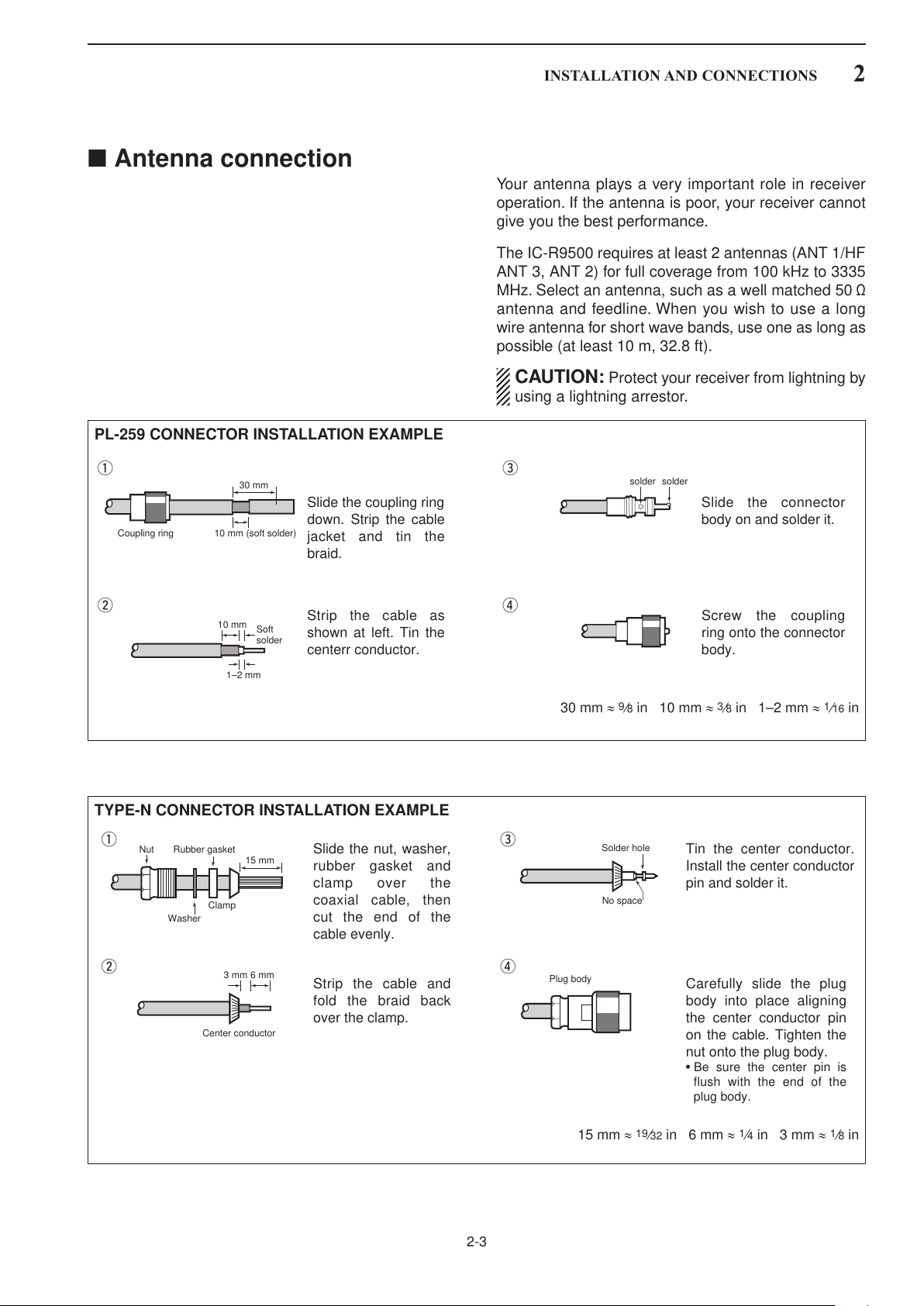
■ Antenna connection
30 mm
10 mm (soft solder)
10 mm
1–2 mm
solder solder
Soft
solder
Coupling ring
Slide the coupling ring
down. Strip the cable
jacket and tin the
braid.
Slide the connector
body on and solder it.
Screw the coupling
ring onto the connector
body.
Strip the cable as
shown at left. Tin the
centerr conductor.
q
w
e
r
15 mm
Clamp
3 mm 6 mm
Center conductor
Washer
Nut Rubber gasket
qe
rw
Slide the nut, washer,
rubber gasket and
clamp over the
coaxial cable, then
cut the end of the
cable evenly.
Tin the center conductor.
Install the center conductor
pin and solder it.
Carefully slide the plug
body into place aligning
the center conductor pin
on the cable. Tighten the
nut onto the plug body.
•Besure the center pin is
flush with the end of the
plug body.
Strip the cable and
fold the braid back
over the clamp.
Plug body
No space
Solder hole
PL-259 CONNECTOR INSTALLATION EXAMPLE
INSTALLATION AND CONNECTIONS
2
Your antenna plays a very important role in receiver
operation. If the antenna is poor, your receiver cannot
give you the best performance.
The IC-R9500 requires at least 2 antennas (ANT 1/HF
ANT 3, ANT 2) for full coverage from 100 kHz to 3335
MHz. Select an antenna, such as a well matched 50 Ω
antenna and feedline. When you wish to use a long
wire antenna for short wave bands, use one as long as
possible (at least 10 m, 32.8 ft).
CAUTION: Protect your receiver from lightning by
using a lightning arrestor.
30 mm ≈ 9⁄8 in 10 mm ≈ 3⁄8 in 1–2 mm ≈ 1⁄16 in
TYPE-N CONNECTOR INSTALLATION EXAMPLE
2-3
15 mm ≈ 19⁄32 in 6 mm ≈ 1⁄4 in 3 mm ≈ 1⁄8 in

2
FH M4×12 mm
FH M4×16 mm
PH M4×8 mm
q
w
PH: Pan head
FH: Flat head
FH M4×16 mm
FH: Flat head
INSTALLATION AND CONNECTIONS
■ TV jumper cable connection (except for USA versions)
Connect the RCA cable between [VIDEO IN] and
[VIDEO OUT].
When connecting external video equipment, connect
the unit between [VIDEO IN] and [VIDEO OUT] con-
nectors.
■ Carrying handle attachment
q Remove the 2 screws from side panel for both
side.
w Attach the supplied Carrying handles as shown at
■ Rack mounting handle detachment
When removing the rack mounting handles, use the
supplied screws for attach the side plates.
q Remove the 6 screws from the rack mounting han-
w Attach the removed side plates to original position,
left.
dles for both side. And remove the rack mounting
handles and side plates.
then tighten the supplied 4 screws (FH M4× 12).
Tighten the supplied 2 screw (PH M4×8) for hiding
screw holes for both side.
CAUTION: NEVER replace the any other than
specified screws for side plate atachment or hid-
ing screw holes. If long screw is used, it is caused
to damage the receiver’s inside board.
2-4
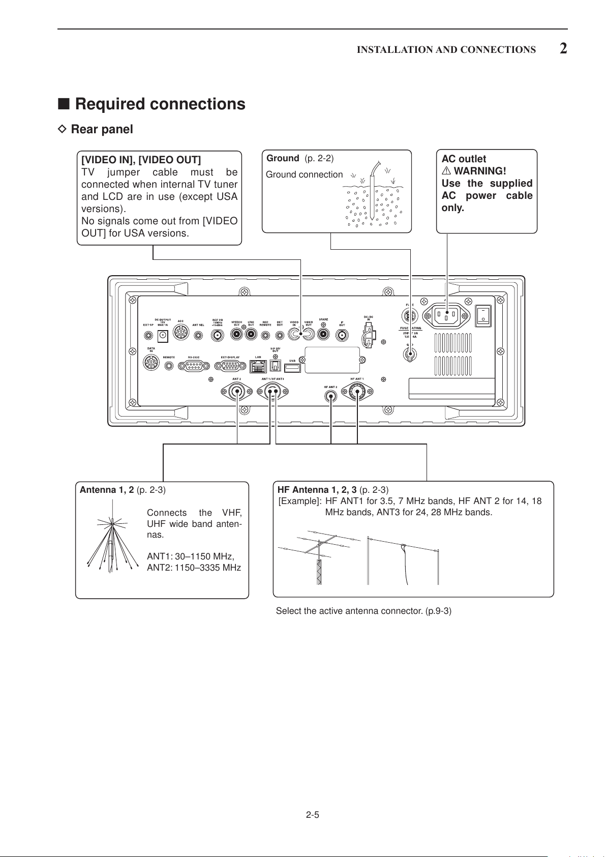
■ Required connections
HF Antenna 1, 2, 3 (p. 2-3)Antenna 1, 2 (p. 2-3)
Connects the VHF,
UHF wide band anten-
nas.
ANT1: 30–1150 MHz,
ANT2: 1150–3335 MHz
Select the active antenna connector. (p.9-3)
[Example]: HF ANT1 for 3.5, 7 MHz bands, HF ANT 2 for 14, 18
MHz bands, ANT3 for 24, 28 MHz bands.
Ground (p. 2-2)
Ground connection
AC outlet
R WARNING!
Use the supplied
AC power cable
only.
[VIDEO IN], [VIDEO OUT]
TV jumper cable must be
connected when internal TV tuner
and LCD are in use (except USA
versions).
No signals come out from [VIDEO
OUT] for USA versions.
D Rear panel
INSTALLATION AND CONNECTIONS
2
2-5

2
[REC REMOTE],
[REC OUT] (p. 2-8)
Connects a tape re-
corder or other au-
dio equipment.
Accepts headphones
with 8–16 Ω impe-
dance.
Headphones
External speaker (p. 14-4)
ACC socket
(pgs.2-12)
DATA socket
(pgs.2-12)
Antenna 1, 2
Connects a pre-amplifier,
converter, etc.
SP-20
(option)
[REMOTE], [RS-232C] (p. 13-2)
Used for computer control and transceive
operation.
The optional CT-17 is required when con-
necting a PC to [REMOTE].
[DC OUTPUT]
Outputs regulated 15 V (approx.)
DC for external equipment power
supply. (max. 1 A capacity)
Connects an external pow-
er supply (DC 13.5—15 V at
least 10 A).
Only regulated DC power
may be connected.
[DC-DC IN]
INSTALLATION AND CONNECTIONS
■ Advanced connections
D Front panel
D Rear panel—1
2-6
 Loading...