


ADVANCED MANUAL
COMMUNICATIONS RECEIVER
iR30
INTRODUCTION
1 POWER SUPPLY
2 microSD CARD
3
RECORDING AND PLAYING BACK
4 MEMORY OPERATION
5 GPS OPERATION
6 MENU SCREEN
7 OTHER FUNCTIONS
8 Bluetooth® OPERATION
9 UPDATING THE FIRMWARE
10 OPTIONS
11 SPECIFICATIONS

INTRODUCTION
Thank you for choosing this Icom product. This product is designed and built with Icom’s
state of the art technology and craftsmanship. With proper care, this product should
provide you with years of trouble-free operation.
■ About the IC-R30 manuals
The following manuals are supplied for your IC-R30.
Basic manual (Supplied with the IC-R30)
Instructions for the basic operations, precautions.
Advanced manual (This manual)
Instructions for the advanced operations, as shown below.
• Battery operation*
• Using a microSD card*
• Recording the received audio*
• Memory operation*
• GPS operation*
• Menu screen*
• Other functions*
• Bluetooth
• Firmware updating
• Options*
• Specications
R *Only the basic instructions are described in the BASIC MANUAL.
®
operation*
Icom, Icom Inc. and the Icom logo are registered trademarks of Icom Incorporated
(Japan) in Japan, the United States, the United Kingdom, Germany, France, Spain,
Russia, Australia, New Zealand, and/or other countries.
NXDN is a trademark of Icom Incorporated and JVC KENWOOD Corporation.
dPMR is a trademarks of the dPMR MoU Association.
Adobe, Acrobat, and Reader are either registered trademarks or trademarks of Adobe
Systems Incorporated in the United States and/or other countries.
Microsoft and Windows are registered trademarks of Microsoft Corporation in the United
States and/or other countries.
IOS is a trademark or registered trademark of Cisco in the U.S. and other countries and
is used under license.
Apple, iPhone and iPad are trademarks of Apple Inc., registered in the U.S. and other
countries.
The iPhone trademark is used under license from AiPhone Co., Ltd.
Android and Google Play are registered trademarks or trademarks of Google Inc, and
Google is registered trademark or trademark of Google, Inc.
The Bluetooth word mark and logos are registered trademarks owned by Bluetooth SIG,
Inc. and any use of such marks by Icom inc. is under license.
Other trademarks and trade names are those of their respective owners.
i

INTRODUCTION
Functions of Adobe® Acrobat® Reader
The following functions and features can be used with Adobe Acrobat Reader.
• Keyword search
Click “Find” (Ctrl+F) or “Advanced Search” (Shift+Ctrl+F) in the Edit menu
to open the search screen.
This is convenient when searching for a particular word or phrase in this
manual.
* The menu screen may differ, depending on the Adobe Acrobat Reader version.
• Find screen
• Advanced search screen
®
Click to open the nd or search
screen or advanced search screen.
ii

INTRODUCTION
Functions of Adobe® Acrobat® Reader® (Continued)
• Printing out the desired pages.
Click “Print” in the File menu, and then select the paper size and page
numbers you want to print.
* The printing setup may differ, depending on the printer. Refer to your
printer’s instruction manual for details.
* Select "A5" size to print out the page in the original manual size.
• Read Out Loud feature.
The Read Out Loud feature reads aloud the text in this PDF.
Refer to the Adobe Acrobat Reader Help for the details.
( This feature may not be usable, depending on your PC environment
including the operating system.)
* The screen may differ, depending on the Adobe Acrobat Reader version.
iii

INTRODUCTION
Entering and editing text
The usable characters are alphabets, numbers and symbols.
To enter characters
• To insert a text, move the cursor to a place to enter, then push the keypad.
L You can elect a character by rotating [DIAL], or pushing D-pad (Up) or D-pad (Down).
• When the character type is “AB” or “ab,” and while entering a character, push [QUICK] to
select upper case or lower case letters.
• To clear a character, push [CLEAR].
• To consecutively clear characters, continuously hold down [CLEAR].
Selects a character
Opens the Entry Mode Select window
Selects
a character*
Sets the entry
Clears
the entry
Moves the cursor
to the left
*Only when the DIAL/VOL Switch function is ON.
Selects
a character
Moves the cursor
to the right
Selects
a character
Keaypad
Entry Mode Select window
Alphabet
(Upper case)
Character type Selectable characters and symbols
AB
ab
12
!”#
Alphabet
(Lower case)
Number
A to Z, 0 to 9, (space)
a to z, 0 to 9, (space)
0 to 9 , (space)
! " # $ % & ’ ( ) * + , - . / : ; < = > ? @
[ \ ] ^ _ ` { | } ˜ (space)
iv

INTRODUCTION
Entering and editing text (Continued)
D Usable characters
The usable characters and symbols, and the maximum characters differ, depending on
the item. See the following list for details.
Category Item Character type
Memory mode
Program scan Scan name [AB] [ab] [12] [!”#] 16 –
P-LINK Scan Link name [AB] [ab] [12] [!”#] 16 –
SD Card
GPS Memory
Bluetooth
Memory name [AB] [ab] [12] [!”#] 16 –
Bank name [AB] [ab] [12] [!”#] 16 –
Save Setting [AB] [ab] [12] [!”#] 20 / : ; * < > p. ?-?
Export [AB] [ab] [12] [!”#] 20 / : ; * < > p. ?-?
Memory name [AB] [ab] [12] [!”#] 16 – p. ?-?
Group name [AB] [ab] [12] [!”#] 16 – p. ?-?
®
Device name [AB] [ab] [12] 8 – p. ?-?
Maximum
characters
Illegal
characters
[AB]: A to Z, 0 to 9, (space)
[ab]: a to z, 0 to 9, (space)
[12]: 0 to 9, (space)
[!”#]: ! " # $ % & ’ ( ) * + , - . / : ; < = > ? @ [ \ ] ^ _ ` { | } ˜ (space)
Ref.
p. ?-?
v

INTRODUCTION
Entering and editing text (Continued)
D How to enter
Example: Entering “2m Call” as a Memory name of channel 00 in group 00.
1. Push [VFO/MR] to enter the Memory mode.
2. Push [MW].
3. Select “Manage Memory.”
(Rotate [DIAL] to select it, then push [ENTER].)
4. Select group “00.”
5. Select channel “00,” then push [QUICK].
6. Select “Edit”.
• The Edit screen is displayed.
7. Select “NAME.”
• The Memory name edit screen is displayed.
8. Push [QUICK] to select a character type.
9. Push [MHz] to select “2.”
L To enter symbols, select [!”#].
10. Repeat steps 8 ~ 9 to enter a name.
11. After entering, push [ENT].
• Returns to the Edit screen and the entered name is displayed.
12. Push [QUICK], then select “<<Overwrite>>.”
• A conrmation dialog appears.
13. Select <YES>.
• A beep sounds, then returns to the Memory mode.
Group 00
Character type Number “2” “2m Call” is entered
Channel 00 “NAME” item
vi

INTRODUCTION
About the air ventilation holes
There are air ventilation holes on the receiver body and battery pack/case that adjust the
air pressure inside of the receiver.
L Applying a sticker over the ventilation hole blocks the air pressure adjustment, and may
decrease the audio output level.
L Damage to the ventilation sheet may reduce the water protection capability.
Here is an air
ventilation hole.
Here is an air
ventilation hole
under the sheet.
Ventilation sheet
Here is an air
ventilation hole.
vii

POWER SUPPLY
■About the Battery Case ……………………………………… 1-2
DBattery life …………………………………………………… 1-2
DAbout the battery replacement …………………………… 1-2
DAbout the safety use of battery case ……………………… 1-3
■Charging with a USB cable ………………………………… 1-4
Section 1
1-1

POWER SUPPLY
点滅
1
■ About the Battery Case
z Remove the battery case, then install three AA (LR6) size alkaline batteries, as
described below.
Be sure to observe
the correct polarity.
Battery case
(Optional BP-293)
Install three AA (LR6)
size alkaline batteries
D Battery life
The approximate battery life (operating time) is approximately 4 hours under the
following assumptions:
• Dualwatch function: ON
(A band: Receiving, B band: Stand-by, Power Save function: ON (Auto (Short))
L The battery life may differ, depending on the operating style, or the installed alkaline
batteries.
L The batteries may seem to have low capacity when used in low temperatures. Keep the
case warm in low temperature environments.
D About the battery replacement
When the alkaline batteries are almost exhausted, “LOW BATTERY” is displayed,
then the receiver is automatically turned OFF. Replace all batteries with new alkaline
batteries.
L When the BP-293 battery case is attached to the receiver, the battery icon cannot display
the battery capacity of the alkaline batteries. The battery icon stays as “
not reect with the true battery capacity.
,” and it does
1-2

POWER SUPPLY
1
D About the safety use of the battery case
• When installing batteries, make sure they are all the same brand, type and capacity.
Also, do not mix new and old batteries together.
• Keep the battery terminals clean. It’s a good idea to occasionally clean them.
• Never incinerate used battery cells since the internal battery gas may cause them to
rupture.
• Never expose a detached battery case to water. If the battery case gets wet, be sure to
wipe it dry before using it.
• Never use batteries whose insulated covering is damaged.
CAUTION: Install only alkaline batteries into the BP-293.
NOTE:
• Remove the alkaline batteries when battery case is not used.
• Do not connect a USB cable while the battery case is attached to the receiver.
The operation while connecting a USB is not guaranteed.
TIP:
• The BP-293 meets IPX4 requirements for waterproof protection, only when it is
attached to the IC-R30.
• The batteries may seem to have low capacity when used in low temperatures. Keep
the case warm in low temperature environments.
1-3

POWER SUPPLY
1
■ Charging with a USB cable
You can charge the battery pack with the supplied USB cable (A-microB type).
Power adapter or external battery
(User supplied)
Turn OFF
NOTE:
• BE SURE to turn OFF the receiver before charging the battery pack. Otherwise the
attached battery pack cannot be charged completely, or it will take much longer to charge.
• If you use a third party USB cable, you may not be able to charge:
- Depending on your USB cable or power adapter.
- When using a USB hub or connecting to a low output USB port.
TIP:
• When the battery pack is fully charged, the charging will automatically stop.
If you leave the receiver connected to the USB cable, the charging will automatically start
when the battery has been almost exhausted.
Even when the receiver power is OFF, a slight current still ows in the circuits. Remove
the battery pack or batteries from the receiver when not using it for a long time. Otherwise,
the installed battery pack or battery case cells will become exhausted, and will need to be
recharged or replaced.
• You can select an option for while the receiver and PC are connected. (p. 6-21)
([MENU] > Function > USB Connect)
USB cable
(A-microB type)
To a USB port
PC
1-4

microSD Card
■About data saved on a microSD card………………………… 2-2
■Saving data onto the microSD card ………………………… 2-2
■Loading the saved data from the microSD card …………… 2-4
■Backing up the data from a microSD card onto a PC ……… 2-5
DAbout the microSD card’s folder ………………………… 2-5
DMaking a backup le on a PC……………………………… 2-6
■Importing or Exporting a CSV format le …………………… 2-9
DImporting ……………………………………………………2-10
DExporting ……………………………………………………2-11
Section 2
2-1

microSD Card
2
■ About data saved on a microSD card
• Receiver data
Memory channel contents, receiver settings, and so on.
• Recorded audio
Recorded received audio data.
• Receive history
Receive history log (Digital signal).
• Position data from the GPS receiver
Position data from the internal GPS receiver.
■ Saving data onto the microSD card
Memory channels and item settings on the menu screen can be saved on a microSD card.
Saving data on the microSD card enables you to easily restore the receiver to its
previous conguration, even if an All reset is performed.
L Data can be saved as a new le or overwritten to an older le.
Saving as a new le
[MENU] > SD Card > Save Setting
1. Push [MENU].
2. Select “Save Setting” in the “SD Card” menu.
(Rotate [DIAL] to select it, then push [ENTER].)
3. Select “<<New File>>.”
L The le name is automatically named in the following manner: Setyyyymmdd_xx
(yyyy: Year, mm: month, dd: day, xx: serial number).
L If you want to change the file name, see page 2-3 for entry details.
4. Push [ENTER].
• A conrmation dialog is displayed.
5. Select “YES,” and then push [ENTER].
L Push [CLEAR] to return to the Main screen.
2-2

microSD Card
2
■ Saving data onto the microSD card
Saving with a different le name
[MENU] > SD Card > Save Setting
1. Push [MENU].
2. Select “Save Setting” in the “SD Card” menu.
(Rotate [DIAL] to select it, then push [ENTER].)
3. Select “<<New File>>.”
4. Push [CLEAR] to delete the selected character.
L Holding down [CLEAR] deletes the all characters.
5. After entering a file name, push [ENTER].
L Refer to page iv for character entry details.
6. Select “YES,” and then push [ENTER].
L Push [CLEAR] to return to the Main screen.
Saving in an earlier version
[MENU] > SD Card > Save Form
Select “Older Ver (X.XX - X.XX)” in the “Save Form” item (p.6-34) to save the setting le
that is saved in an earlier version to an earlier rmware version.
2-3

microSD Card
2
■ Loading the saved data from the microSD card
The saved memory channels, item settings on the menu screen can be copied to
another IC-R30. This function is convenient when sharing data with other IC-R30s.
L Saving the current data on to a microSD card is recommended before loading the data.
Example: Loading setting data “Set20180216_01”
[MENU] > SD Card > Load Setting
1. Push [MENU].
2. Select “Load Setting” in the “SD Card” menu.
(Rotate [DIAL] to select it, then push [ENTER].)
3. Select the desired file to be loaded, then push [ENTER].
• A conrmation dialog is displayed.
4. Select “YES,” and then push [ENTER].
• Starts the le check. After checking, starts settings data loading.
• After loading, “COMPLETED! Restart the IC-R30.” is displayed.
5. Restart the IC-R30.
2-4

microSD Card
2
■ Backing up the data from a microSD card onto
a PC
A backup le restoring, even if the data on the microSD card is accidentally deleted or
corrupted.
D About the microSD card’s folder
The folders contained in the microSD card are as follows:
w Csv e GpsMemory
q IC-R30
y Gps
u RXLog
i Setting
o Voice
r MemoryCh
t ScanEdge
!0 yyyymmdd
!0 yyyymmdd
q IC-R30 folder
The folders created in the IC-R30 are in
this folder.
w Csv folder
Contains the GPS Memory, Memory
channels, Programmable Scan Edges
Import/Export folders.
e GpsMemory folder
Contains the GPS Memory in the “csv”
format to import or export.
r MemoryCh folder
Contains the Memory channels in the
“csv” format to import or export.
t ScanEdge folder
Contains the Programmable Scan Edges
in the “csv” format to import or export.
y Gps folder
GPS logging data is stored in the “log”
format.
u RXLog folder
RX record log data is stored in the “csv”
format.
i Setting folder
IC-R30’s setting data is stored in the “csv”
format.
o Voice folder
The recorded RX recorder audio date
folders are created in the Voice folder.
!0 yyyymmdd folder
Recorded audio le is stored in the “wav”
format.
The folder name is automatically created
in the following format:
yyyymmdd (yyyy:Year, mm:month, dd:day)
2-5

microSD Card
2
■ Backing up the data stored on the microSD card onto a PC (Continued)
D Making a backup le on a PC
You can make a backup of the data that is stored on a microSD card, through a USB
cable.
Operation on the receiver
[MENU] > Function > USB Connect > SD Card Mode
1. Connect the receiver to a PC using a USB cable.
2. Turn ON the receiver power.
3. Push [MENU].
4. Select “SD Card Mode” in the “Function” menu.
(Rotate [DIAL] to select it, then push [ENTER].)
• A con rmation dialog appears.
5. Select “YES.”
• Displays the IC-R30 folder on the PC screen.
TIP: You can also read or write the data using the microSD card and a card reader
(user supplied), without a USB cable. Remove the microSD card that contains the data
from the IC-R30, then read it on the PC using the card reader.
2-6

microSD Card
2
■ Backing up the data stored on the microSD card onto a PC
D Making a backup le on a PC (Continued)
Operation on the PC
NOTE: If the “AutoPlay” screen is not displayed as shown below, click the Folder icon on
the task bar.
Example: Saving the data in the folder “Backup” on drive C.
1. Put the mouse cursor on “USB Drive,” then right-click.
L The screen may differ, depending on your PC environment.
2. Click [Copy].
Right-click
Click
3. Right-click on the destination folder where the back up files are saved, then click
[Paste]. (Example: Folder “Backup” on drive C.)
• The data stored on the microSD card is saved on the PC hard disk.
Right-click
Click
(Continued on the next page.)
2-7

microSD Card
2
■ Backing up the data stored on the microSD card onto a PC
D Making a backup le on a PC (Continued)
4. To disconnect the IC-R30 from the PC, click the “Eject Mass Storage Device.”
Click
Right-click
5. When “Safe To Remove Hardware” is displayed, disconnect the USB cable from the
PC.
2-8

microSD Card
2
■ Importing or Exporting a CSV format le
You can importing or exporting a Comma Separated Values (CSV) format le to or from
the microSD card. You can separately import or export the following data:
• Memory channels
• Programmable Scan Edges
• GPS Memories
NOTE: The receiver cannot display a le that has a le name longer than 10
characters. In this case, rename it using 10 characters or less.
When you export the data in a CSV format le using the CS-R30 (option), make sure to
name it using 10 characters or less.
TIP: CSV is a le format that is used to read or write the IC-R30’s setting data.
You can import the setting data to a PC, and edit it using the CS-R30.
2-9

microSD Card
2
■ Importing or Exporting a CSV format le
D Importing
TIP: Before importing, make a backup le of all the receiver’s data to the microSD card
in case of data loss.
Example: Importing memory channels.
[MENU] > SD Card > Import/Export > Import
1. Push [MENU].
2. Select “Import” in the “SD Card” menu.
(Rotate [DIAL] to select it, then push [ENTER].)
3. Select “Memory CH,” and then push [ENTER].
4. Select the Memory group that contains the memory channel to import, then push
[ENTER]. (Example: Group 03)
NOTE: If you select “ALL,” all the memory channels except in the Auto Memory
Write channel group (A:Auto MW CH) and Skip channel group (S:SKIP CH) are
deleted, before importing.
5. Select the CSV file to import.
• A conrmation dialog is displayed.
6. Select “YES,” and then push [ENTER].
• Starts to import.
L After importing ends, “COMPLETED! Restart the IC-R30.” is displayed.
7. Restart the IC-R30 to complete the importing.
2-10

microSD Card
2
■ Importing or Exporting a CSV format le
D Exporting
Saving as a new le
Example: Exporting memory channels.
[MENU] > SD Card > Import/Export > Export
1. Push [MENU].
2. Select “Export” in the “SD Card” menu.
(Rotate [DIAL] to select it, then push [ENTER].)
3. Select “Memory CH,” and then push [ENTER].
4. Select the Memory group that contains the memory channels to export, then push
[ENTER]. (Example: Group 00)
L If you export all memory channels, select “ALL.”
5. Select the “<<New File>>.”
• The FILE NAME screen is displayed.
• The le name is automatically named in the following manner Mch*yyyymmdd_xx (yyyy:
Year, mm: month, dd: day, xx: serial number)
* “Pscan” for Programmable Scan Edges. “Gps” for GPS Memory.
L Refer to page iv for character entry details.
L If you want to return to the Main screen, push [SQL].
6. Push [ENTER].
• A conrmation dialog appears.
7. Select “YES,” and then push [ENTER].
• Starts to export.
L Push [CLEAR] to return to the Main screen.
TIP: Saving on an existing le (Overwrite)
In Step 5, select a le to overwrite.
2-11

RECORDING AND PLAYING BACK
■Recording ………………………………………………………… 3-2
DStarting recording …………………………………………… 3-2
DStopping recording …………………………………………… 3-2
■Playing back ……………………………………………………… 3-3
DPlayback screen ……………………………………………… 3-4
■Player/recorder set screen ……………………………………… 3-5
■Deleting a le or folder ………………………………………… 3-6
DDeleting a folder ……………………………………………… 3-6
DDeleting a le ………………………………………………… 3-7
■Checking the le information …………………………………… 3-8
■Checking SD card information ………………………………… 3-9
■Playing back on a PC ……………………………………………3-10
Section 3
3-1

RECORDING AND PLAYING BACK
3
■ Recording
The microSD and microSDHC cards are not supplied by Icom. User supplied.
D Starting recording
z Push [zREC].
• “Recording started...” is briey displayed.
TIP:
• “
” is displayed during recording.
• “
” is displayed while recording is paused.
• If a single band display is selected, only the audio
signal received on the band is recorded, even when the
“REC Operation” item is set to “A/B Link.”
• The recording continues until you push [zREC], or the
free space on the microSD card has run out.
• When the recording le’s content reaches 2 GB, the
receiver continues to record, but to a new le.
D Stopping recording
1. Push [zREC] again.
• A conrmation dialog is displayed.
2. Select “YES,” and then push [ENTER].
• “Recording stopped.” is briey displayed.
[zREC]
TIP:
• As the default setting, the recording is paused while the squelch is closed, and
resumes when a signal is received. But you can set to continue recording even while
no signal is received.
([MENU] > RX Recorder > Recorder Set > RX REC Condition)
• You can select to record the received audio from only the main band or both the main and
sub bands. (p. 3-5)
([MENU] > RX Recorder > Recorder Set > REC Operation)
(p. 3-5)
3-2

RECORDING AND PLAYING BACK
3
■ Playing back
[MENU] > RX Recorder > Play Files
1. Push [MENU].
2. Select “Play Files” in the “RX Recorder” menu.
(Rotate [DIAL] to select it, and then push [ENTER].)
• The folder list is displayed.
3. Select a folder that contains the file you want to playback, and then push [ENTER].
• The le list is displayed.
L The folder is named in the following manner, “yyyymmdd” (yyyy: Year, mm: month, dd:
day).
4. Select a file, and then push [ENTER].
• The VOICE PLAYER screen appears and starts playing back the audio.
L Push [ENTER] to pause while playing.
L On the VOICE PLAYER screen, you can select the le to play by pushing D-pad (Up)
or (Down).
5. Push [CLEAR] to stop playing.
• The le list is displayed.
L Push [CLEAR] again to return to the Main screen.
Playing le’s description
TIP: Selecting the record le type to display.
In Step 4 above, push [QUICK], then select “Display File” and
select the record le type to display.
• ALL: Displays all recorded les.
• A only: Displays only the audio le that was recorded
• B only: Displays only the audio le that was recorded
on the A band.
on the B band.
3-3

RECORDING AND PLAYING BACK
3
■ Playing back (Continued)
D Playback screen
The number of le being played back/
The total number of recorded les.
Clockwise: Fast Forward
Counter Clockwise: Fast Rewind
Recording start
date and time
Frequency and
mode.
Band (A/B)
Call signs*
Playback elapsed time/Total recorded
*When the receive mode is D-STAR, the received signal’s call sign is displayed.
CALLER: The call sign of the caller station.
CALLED: The call sign of the called station.
RPT: The call sign of the repeater you received the call from.
Operations on the Playback screen
• [DIAL]: Rotate to set the playback point. The point is set in 1/20 duration of the le,
regardless of the total duration.
• D-pad (Left)/(Right): Push to fast forward or rewind to the skip time point.
(Default: 10 seconds)
L You can change the Skip Time. (p. 3-5)
[MENU] > RX Recorder > Player Set > Skip Time
Pause/Play
Rewind to the
skip time
Open the Playback
Menu screen
Close the playback
screen
Play the previous le.
Fast forward
to the skip time
Play the next le.
L If you push this key within the rst 1 second of the le, the end of the previously recorded
le will play back.
3-4

RECORDING AND PLAYING BACK
3
■ Player/recorder set screen
You can change the recording settings on the RX RECORDER screen. And you can
also change the fast forward or rewind skip time on the PLAYER SET screen.
Recording condition
[MENU] > RX Recorder > Recorder Set > RX REC Condition
Set to “Always” to continue recording even while no signal is
received.
As the default setting, the recording is paused while the squelch
is closed, and resumes when a signal is received.
Recording le split
[MENU] > RX Recorder > Recorder Set > File Split
Turn the File Split function ON or OFF.
When “ON” (Default) is selected, the recorded audio le is
newly created, according to the File Split setting.
See page 6-8 for the le split condition or operation.
Recording operation
[MENU] > RX Recorder > Recorder Set > REC Operation
Set to “A/B separate” if you want to separately start or stop
recording on the selected band (MAIN band).
As the default setting (A/B Link), recording simultaneously
starts on the MAIN and SUB bands.
Skip setting
[MENU] > RX Recorder > Player Set > Skip Time
Set to the skip amount for fast forward or rewind in seconds.
(default: 10sec)
3-5

RECORDING AND PLAYING BACK
3
■ Deleting a le or folder
NOTE: Deleted le or folder cannot be recalled. All the les in the folder are also
deleted.
Before deleting any le or folder, back up the data onto your PC.
D Deleting a folder
[MENU] > RX Recorder > Play Files
1. Push [MENU].
2. Select “Play Files” in the “RX Recorder” menu.
(Rotate [DIAL] to select it, and then push [ENTER].)
• The folder list is displayed.
3. Select a folder to delete, and then push [QUICK].
4. Select “Delete,” and then push [ENTER].
• A conrmation dialog is displayed.
5. Select “YES,” and then push [ENTER].
• The selected folder is deleted.
L Push [CLEAR] to return to the Main screen.
TIP: Deleting all folders
In Step 4 above, select “Delete All Folders.”
3-6

RECORDING AND PLAYING BACK
3
■ Deleting a le or folder (Continued)
D Deleting a le
[MENU] > RX Recorder > Play Files
1. Push [MENU].
2. Select “Play Files” in the “RX Recorder” menu.
(Rotate [DIAL] to select it, and then push [ENTER].)
• The folder list is displayed.
3. Select a folder that contains the file you want to delete,
and then push [ENTER].
• The le list is displayed.
4. Select a file to delete, and then push [QUICK].
5. Select “Delete,” and then push [ENTER].
• A conrmation dialog is displayed.
6. Select “YES,” and then push [ENTER].
• The selected le is deleted.
L Push [CLEAR] to return to the Main screen.
TIP: Deleting all les
In Step 5 above, select “Delete All.”
L If “Display File” is set to “A only” or “B only,” only displayed les are deleted.
“Display File” is “ALL”
“Display File” is “A only”
“Display File” is “B only”
3-7

RECORDING AND PLAYING BACK
3
■ Checking the le information
The IC-R30 can display the recorded le’s receive frequency, mode, date, and so on.
[MENU] > RX Recorder > Play Files
1. Push [MENU].
2. Select “Play Files” in the “RX Recorder” menu.
(Rotate [DIAL] to select it, and then push [ENTER].)
• The folder list is displayed.
3. Select a folder that contains the file you want to check, and then push [ENTER]..
• The le list is displayed.
4. Select a file to check, and then push [QUICK].
5. Select “File Information,” and then push [ENTER].
• The le information window is displayed.
• Rotate [DIAL] to change the information display.
L Push [CLEAR] to close the window.
TIP: Checking the folder information
In Step 3 above, select “Folder Information”
to check the folder information.
3-8

RECORDING AND PLAYING BACK
3
■ Checking the le information (Continued)
File information examples
z Rotate [DIAL] in the information window, to change the information display.
L Some items are not displayed, depending on the receive mode.
■ Checking SD card information
[MENU] > SD Card > SD Card Info
1. Push [MENU].
2. Select “SD Card Info” in the “SD Card” menu.
(Rotate [DIAL] to select it, and then push [ENTER].)
• The SD card’s free space and capacity are displayed.
L Push [CLEAR] to return to the Main screen.
3-9

RECORDING AND PLAYING BACK
3
■ Playing back on a PC
You can also playback on a PC.
L The recorded information (frequency, date, and so on) is not displayed.
L These instructions are based on Microsoft Windows 10.
Example: Connecting the IC-R30 and PC with a USB cable, then playing an audio le on
a PC.
[MENU] > Function > USB Connect
1. Connect the IC-R30 and PC with a USB cable.
IC-R30
USB cable
(A-microB type)
To a USB port
2. Push [MENU].
3. Select “USB Connect” in the “Function” menu.
(Rotate [DIAL] to select it, and then push [ENTER].)
4. Select “SD Card Mode.”
• A conrmation dialog is displayed.
5. Select “YES,” and then push [ENTER].
• The IC-R30 is connected to the PC in the SD Card mode, and the SD card folder is
displayed on the PC screen.
L If the SD card folder is not displayed, click “Open folder to view les” to open the SD
card folder.
PC
3-10
(Continued on the next page.)

RECORDING AND PLAYING BACK
3
■ Playing back on a PC (Continued)
6. Double-click the “IC-R30” folder.
Double-click
7. Double-click the “Voice” folder.
Double-click
8. Double-click the folder that contains the file you wan to play. (Example: 20180403)
Double-click
9. Double-click the file to play. (Example: 20180403_06581.wav)
Double-click
• Starts playing back the audio on the PC.
NOTE:
• The operations while playing back may differ, depending on the application. Refer to the
application’s instruction manual for details.
• When the le does not playback, even if you double click the le, download an appropriate
software application. (Example: Windows Media
®
Player)
3-11

MEMORY OPERATION
■ General description ..................................................... 4-2
D Memory channel contents ....................................... 4-2
■ Memory management ................................................. 4-3
D Memory channel tree view ...................................... 4-3
D Checking a Memory channel contents .................... 4-3
■ Selecting a memory channel ....................................... 4-4
D Selecting with [DIAL] ............................................... 4-4
D Selecting with the keypad ....................................... 4-4
■ Writing a memory channel .......................................... 4-5
D Selecting and Writing a channel ............................. 4-5
D Write to a New Channel .......................................... 4-6
D Write to the Selected Channel ................................ 4-7
■ Copying Memory contents to the VFO ........................ 4-8
■ Copying the Memory contents to another channel...... 4-9
■ Moving the Memory contents to another channel
in a different group .................................................... 4-10
■ Inserting a blank channel ........................................... 4-11
■ Entering a group/memory name................................ 4-12
■ Selecting a memory name display ............................ 4-13
■ Clearing a Memory contents ..................................... 4-14
Section 4
4-1

MEMORY OPERATION
4
■ General description
The Memory mode is very useful to quickly select often-used operating settings.
The receiver has 2000 regular memory channels and 100 memory groups. Up to 100
channels can be assigned to a group.
NOTE:
Memory data may be erased by static electricity, electric transients, and other causes.
In addition, they can be erased by a malfunction and during repairs. Therefore, we
recommend that memory data be backed up by saving it to a microSD card or to a PC.
• The microSD card is user supplied.
• The CS-R30
backup the memory data.
D Memory channel contents
A single memory channel stores following items.
L Contents differs, depending on the receive mode.
• Memory name
• Frequency
• Tuning step
• Receive mode
• Duplex direction (DUP+/DUP–)
• Frequency offset
• RF Gain setting
• Scan skip setting
• Tone squelch or DTCS squelch setting*
• VSC (Voice Squelch Control) setting*
• D.SQL (Digital code squelch) setting*
• Descrambler setting*
• Decryption setting*
• GPS position data
cloning software that is included on the supplied CD can also be used to
1
2
3
4
5
1
Only FM and FM-N
*
2
*
Only FM, FM-N, WFM, AM and AM-N
3
*
Only Digital
4
*
Only dPMR
5
*
Only NXDN-VN, NXDN-N and DCR
4-2

MEMORY OPERATION
4
■ Memory management
D Memory channel tree view
Group 00
00
99
Manage Memory
Group 99
00
99
A:Auto MW CH*
1
000
199
S:SKIP CH*
2
00
99
*1 Automatically writes when a signal is received.
2
*
Skips the set frequency during a scan.
(Hold down [SKIP] for 1 second.)
D Checking a Memory channel contents
[MENU] > Manage Memory > (Memory Group)
1. Push [MENU].
2. Select “Manage Memory” in the menu.
(Rotate [DIAL] to select it, and then push [ENTER].)
• The Memory Group list is displayed.
3. Select a group that contains the Memory channel you want to check, and then push
[ENTER].
• The Memory Channel list is displayed.
4. Select a channel, and then push [ENTER].
• The contents in the selected Memory channel are displayed.
L Rotate [DIAL] to scroll the screen.
L Push [CLEAR] to return to the Main screen.
TIP: Editing the Memory channel contents
In Step 4 above, push [QUICK] and select “Edit”
to edit the selected Memory channel contents.
4-3

MEMORY OPERATION
4
■ Selecting a memory channel
D Selecting with [DIAL]
1. Push [VFO/MR] to select the Memory mode.
2. Push [BAND] to select a group.
3. Rotate [DIAL] to select a Memory channel.
TIP: Selecting a Memory channel beyond the group
You can sequentially select a channel in a different group.
1. Push [QUICK].
2. Select “Channel Select Group Range.”
(Rotate [DIAL] to select it, and then push [ENTER].)
3. Select “All Groups.”
D Selecting with the keypad
1. Push [VFO/MR] to select a Memory mode.
2. Push [BAND] to select a group.
3. Push [F-INP] to select the Memory channel.
• The selected group and “-” (hyphen) are displayed.
4. Push the numeric keys to enter the desired memory channel number.
• When you entered two digits, a beep sounds and the channel is selected.
L If the channel number is one digit, push [ENTER] after you entered the channel
number.
Group 00 Channel 10
4-4
Contents of channel 10

MEMORY OPERATION
4
■ Writing a memory channel
D Selecting and Writing a channel
The channel is written to the selected channel.
Example: Writing 145.000 MHz to channel 16 in group 00.
1. Push [VFO/MR] to select the VFO mode.
2. Rotate [DIAL] to set the frequency and receive mode and so on.
3. Push [MW].
4. Select “Write to Selected CH.”
(Rotate [DIAL] to select it, and then push [ENTER].)
5. Select the channel.
• The selected Memory channel number blinks.
6. Push [MW].
7. Select “Yes.”
• Beeps sound and the memory channel is written.
A blank channel
TIP: Selecting an option on the QUICK menu screen
In Step 5 above, push [QUICK], then select an option,
as shown below.
NAME: Enters to the Memory Name editing mode.
SKIP: Displays the Skip setting screen.
Group Select: Displays the Memory Group list.
<<Write>>: Writes the memory
<<Insert Write>>: Inserts the channel above
the selected memory channel.
4-5

MEMORY OPERATION
4
■ Writing a memory channel (Continued)
D Write to a New Channel
The contents such as frequency and operating mode are written to a blank channel in
the selected group.
Example: Writing 145.000 MHz to a blank channel.
1. Push [VFO/MR] to select the VFO mode.
2. Rotate [DIAL] to set the frequency and receive mode.
3. Hold down [MW] until a beep sounds.
• The memory channel contents are displayed for 2 seconds, and the memory channel is
written to a blank channel.
Content
to be written
Memory group
to belong
4-6

MEMORY OPERATION
4
■ Writing a memory channel (Continued)
D Write to the Selected Channel
The selected channel is overwritten.
Example: Writing 145.000 MHz to channel 08 in group 00.
1. Push [VFO/MR] to select the Memory mode.
2. Rotate [DIAL] to select the channel to be written.
3. Push [VFO/MR] to select the VFO mode.
4. Rotate [DIAL] to set the frequency and receive mode.
5. Push [MW].
6. Select “Write to Selected CH.”
(Rotate [DIAL] to select it, and then push [ENTER].)
• The selected Memory channel blinks.
L You can change the channel to be written, by rotating [DIAL].
7. Push [MW].
• A conrmation dialog appears.
8. Select “Yes.”
• Beeps sound and the memory channel is written, then returns to the VFO mode.
Target Memory channel
Set the frequency
(In the VFO mode)
4-7

MEMORY OPERATION
4
■ Copying Memory contents to the VFO
You can copy the Memory contents to the VFO.
Example: Copying the contents of channel 00 in group 00 to the VFO.
1. Push [VFO/MR] to select the Memory mode.
2. Rotate [DIAL] to select the channel.
• The selected Memory channel number blinks.
3. Push [MW].
4. Select “Copy to VFO.”
(Rotate [DIAL] to select it, and then push [ENTER].)
• A conrmation dialog appears.
5. Select “Yes.”
• Beeps sound and the selected memory contents are copied to the VFO, then returns to
the VFO mode screen.
4-8

MEMORY OPERATION
4
■ Copying the Memory contents to another channel
Example: Copying the contents of channel 03 to channel 46 in the same group (group
1. Push [MW].
2. Select “Manage Memory.”
3. Select the group.
4. Select the channel to copy.
5. Push [QUICK].
6. Select “Copy.”
7. Select the target channel.
00).
(Rotate [DIAL] to select it, and then push [ENTER].)
• “DESTINATION” blinks.
• Beeps sound and the selected memory contents are copied to the selected channel.
Group “00” Channel to copy
Target channel
TIP: Copying the channel to a different group
In Step 6 above, while “DESTINATION” is blinking,
push [QUICK] and select “Group Select.”
• The Memory Group list is displayed.
4-9

MEMORY OPERATION
4
■ Moving the Memory contents to another
channel in a different group
Example: Copying the contents of channel 03 to channel 20 in group 01.
1. Push [MW].
2. Select “Manage Memory.”
(Rotate [DIAL] to select it, and then push [ENTER].)
3. Select the group.
4. Select the channel to move.
5. Push [QUICK].
6. Select “Move.”.
• “DESTINATION” blinks.
7. Push [QUICK].
8. Select “Group Select.”
9. Select the target group.
10. Select the target channel.
• Beeps sound and the selected memory contents are move to the selected channel.
L If the selected channel is not blank, a conrmation dialog appears.
L Select “Insert end of list” to move the channel to the end of the group.
L Channels other than the one that you moved will move up.
TIP: Rearranging the channel list
In Step 6 above, while “DESTINATION” is blinking, perform step 10 to rearrange the
channel list in the group.
4-10

MEMORY OPERATION
4
■ Inserting a blank channel
You can insert a blank channel between 2 Memory channels.
This function is convenient to organize your memory channels.
Example: Inserting a blank channel between channel 5 and 6.
1. Push [MW].
2. Select “Manage Memory.”
(Rotate [DIAL] to select it, and then push [ENTER].)
3. Select the group.
4. Select the channel.
5. Push [QUICK].
6. Select “Insert.”
• Beeps sound and a blank channel is inserted above the selected channel.
L Channels other than the one you moved will move up.
L If you select channel 99 in step 4, 99th channel will be deleted.
(A conrmation dialog will appear.)
TIP: Inserting a blank group
On the Memory Group screen, select a group
and push [QUICK] then select “Insert Group.”
• A blank group is inserted above the selected group.
4-11

MEMORY OPERATION
4
■ Entering a group/memory name
You can assign a name of up to 16 characters to each channel group (00 ~ 99) and
memory channel.
L You cannot change the group name of Auto MW and Skip channels (Groups “A” and “S”).
1. Push [MW].
2. Select “Manage Memory.”
(Rotate [DIAL] to select it, and then push [ENTER].)
3. Select the group.
4. Select the channel to enter a name.
5. Push [QUICK].
6. Select “Edit.”
• The Memory edit screen is displayed.
7. Select “NAME.”
• The Memory name edit screen is displayed.
8. Enter the Memory name, then push [ENTER].
• Returns to the Memory edit screen and the entered Memory name is displayed.
L Refer to page iv to enter characters.
9. Push [QUICK].
10. Select “Overwrite.”
• A conrmation dialog appears.
11. Select “Yes.”
• Beeps sound, then returns to the Memory channel screen.
L Push [CLEAR] to return to the Main screen.
Edit screen Name edit screen
TIP: Entering a group name
On the Memory Group list screen, select a group and
push [QUICK] then select “Edit Name.”
• The Group Name edit window appears.
4-12

MEMORY OPERATION
4
■ Selecting a memory name display
While in the memory mode, the entered memory name can be displayed in 3 different
styles. You can select a display type.
1. Push [VFO/MR] to select the Memory mode.
2. Push [QUICK].
3. Select “Display Type.”
(Rotate [DIAL] to select it, and then push [ENTER].)
4. Select a display type.
L “Freq (Name OFF)” is set as the default.
“Freq (Name OFF)”
Only the frequency is
displayed
Memory name is displayed
“Freq”
under the frequency
“Name”
Frequency is displayed
under the memory name
4-13

MEMORY OPERATION
4
■ Clearing a Memory contents
Contents of entered memories can be cleared (erased), if desired.
L The cleared channel becomes a blank channel.
L You can also clear the Auto MW and Skip channels (Groups “A” and “S”).
NOTE: Cleared memory channel contents cannot be restored.
Example: Clearing channel 01 in group 00.
1. Push [MW].
2. Select “Manage Memory.”
(Rotate [DIAL] to select it, and then push [ENTER].)
3. Select the group.
4. Select the channel to clear.
5. Push [QUICK].
6. Select “Clear.”
• A conrmation dialog appears.
7. Select “Yes.”
• Beeps sound, then returns to the Memory channel list screen.
L Push [CLEAR] to return to the Main screen.
TIP: Deleting a memory channel
In Step 6 above, select “Delete (next CH moves up).”
• The selected channel is deleted.
L You can also delete Memory groups.
Select a group, then select “Delete Group.”
4-14

GPS OPERATION
■ GPS operation features............................................... 5-2
■ Before starting GPS operation .................................... 5-2
D Checking the GPS signal ........................................ 5-2
■ GPS format types ........................................................ 5-3
■ Checking your GPS location ....................................... 5-4
D Displaying Position Data ......................................... 5-4
D GPS POSITION screens and their meanings ......... 5-5
D About the RX screen ............................................... 5-7
D About the Grid Locator .......................................... 5-10
D About the Course .................................................. 5-10
D Setting the display type (MAIN/SUB) .....................5-11
D Changing the GPS Memory or Alarm.....................5-11
D Changing the Compass Direction ......................... 5-12
D Saving your own or a received station’s location .. 5-13
■ Checking GPS information (Sky view screen) .......... 5-14
■ GPS Memory............................................................. 5-15
D Adding a GPS Memory ......................................... 5-15
D Entering the GPS Memory group name ................ 5-19
D Deleting GPS Memory .......................................... 5-20
D Rearranging the display order of the GPS data .... 5-21
■ GPS Alarm ................................................................ 5-22
D Setting the GPS Alarm function to All Memories ... 5-23
■ GPS Logger function ................................................. 5-24
D GPS Logger operating outline............................... 5-24
D Conrming the GPS Logger function .................... 5-25
D Setting the GPS record interval ............................ 5-25
D Setting the GPS record sentence ......................... 5-26
D Viewing the log data on a PC ................................ 5-27
D The <<GPS Logger Only>> mode ........................ 5-28
D <<GPS Logger Only>> outline .............................. 5-28
D Setting the <<GPS Logger Only>> mode ............. 5-28
Section 5
NOTE: Before using the GPS function, read the “GPS OPERATION”
section in the BASIC MANUAL.
5-1

GPS OPERATION
5
■ GPS operation features
GPS Memory (p. 5-15)
You can enter up to 300 GPS Memories in the receiver. By adding destination position
information in a GPS Memory, you can effectively use the GPS Alarm function. The
position information that you acquired can also be entered in a GPS Memory.
GPS Alarm function (p. 5-22)
When a target station comes into the set alarm area, or when you approach an entered
GPS Memory alarm area, the function can sound an alarm. With this function, you can
know when you are approaching the destination.
GPS Logger function (p. 5-24)
The GPS Logger function enables you to save the position data from a GPS receiver onto
a microSD card as a log.
If you use this GPS Logger while driving, you can check your driving history on a mapping
software program.
D-PRS Extension function (p. 5-3)
The D-PRS Extension function enables you to receive Object, Item, and Weather
information in addition to Position data. With this extension, you can simultaneously
receive earthquake information, trafc accident information, emergency information, or
weather information, and so on, along with voice audio in the DV mode.
■ Before starting GPS operation
The receiver has a built-in internal GPS receiver. The GPS receiver’s position data can be
received in any mode.
D Checking the GPS signal
You can check the satellite acquisition status indicated by the GPS icon.
• The GPS icon blinks when receiving.
→ → →
• The GPS icon is displayed when the current location is correctly received.
L INFORMATION
• The time it takes to receive the GPS data may differ, depending on your location.
• The GPS receiver cannot calculate its location if it cannot receive signals from the GPS
satellites.
• The GPS icon is not displayed when “GPS Select” is set to “Manual.”
([MENU] > GPS > GPS Set > GPS Select)
5-2

GPS OPERATION
5
■ GPS format types
GPS position data has 2 TX modes, D-PRS and NMEA. Moreover, with the D-PRS
mode data, 5 position formats. Position (Mobile station/Base station), Object, Item, and
Weather, are selectable.
Examples: When the caller’s TX format is D-PRS Position (Mobile)
D-PRS D-PRS is a function that simultaneously sends position
data received from the internal or external GPS receiver,
using the slow speed data packet space, along with
voice.
Position (Mobile) A station operating from a vehicle, or other position, away
from it's normal base position.
Position (Base) A station operating at home or in a building.
Object Transmitting Object data such as an earthquake
information, satellite track information, and so on.
An Object contains a time stamp.
Item Transmitting Item data such as a trafc accident,
lighthouse, antenna, or DV access point position, and so
on.
An Item does not contain a time stamp.
Weather A station transmitting weather information received from
a weather device.
NMEA A station transmitting position data (NMEA0183) received
from the GPS receiver.
5-3

GPS OPERATION
5
■ Checking your GPS location
You can check your current location.
D Displaying Position Data
1. Confirm is displayed.
2. Push [QUICK].
3. Select “GPS Position.”
(Rotate [DIAL] to select it, and then push [ENTER].)
• Displays the GPS POSITION screen.
4. Rotate [DIAL].
• Changes between the MY (My position), RX (Received
position), MEM (GPS Memory position), or ALM (GPS
Alarm position) screen.
L Push [CLEAR] to return to the Main screen.
Your position (MY)
GPS memory (MEM) GPS alarm (ALM)
Received station (RX) Received station (RX)
(These screens are examples.)
5-4

GPS OPERATION
5
■ Checking your GPS location (Continued)
D GPS POSITION screens and their meanings
L Information
• Pushing [QUICK] to change the compass direction. (p. 5-12)
• About the Grid Locator (p. 5-10)
• About the Course (p. 5-10)
Example for the GPS POSITION screens:
GPS Memory:
Tokyo Skytree
251 ml
0.1 ml
249 ml
GPS Alarm:
Tokyo Big Sight
Caller station
(D-PRS: mobile)
Course: 247 degrees
You
Course: 90 degrees
Speed: 1.4 mph
Speed: 2.3 mph
MY screen (Your position information)
When GPS Select is set to “Manual,” the compass heading and course direction are not
displayed. (p. 6-12)
Compass direction
Your course
heading is East.
Your course
heading.
Displays
My position
(Where you are)
GPS POSITION screen (MY)
NOTE: Latitude, longitude, and altitude data may differ, depending on your received
GPS signal. The altitude data is only for reference.
Latitude
Longitude
Grid Locater
Altitude
Speed
Time
5-5

GPS OPERATION
5
■ Checking your GPS location
D GPS POSITION screens and their meanings (Continued)
RX screen (D-STAR station’s location information)
The displayed itemʼs meanings may differ, and some data may not be displayed,
depending on the callerʼs GPS TX Mode and TX format. (p. 5-3)
L Pushing [QUICK] to change the band (Main/Sub). (p. 5-11)
Example: The caller stationʼs GPS TX Mode is “D-PRS” and its TX format is “Position
Direction from
your location
D-PRS symbol
Distance from
your position
MEM screen (GPS Memory channel’s information)
Direction from your location
ALM screen (GPS Alarm Memory channel’s information)
(Mobile).”
Callerʼs Course direction
Callerʼs Speed
Time the caller acquired
the position data
Caller’s call sign with SSID
Distance from your location
*
Direction from your location
Distance from your location
*
* When a name is not entered in the GPS Memory channel, date and time are displayed
instead of the name. You can change the GPS Memory or GPS Alarm on the GPS
POSITION screen.
(p. 5-5)
5-6

GPS OPERATION
5
■ Checking your GPS location (Continued)
D About the RX screen
D-PRS
Position (Mobile)
Moving symbol Course direction
and speed
Object Item
Time that the caller
sent the Object’s data.
Position (Base)
Speed and course
you are heading
For an Item station, Time is not displayed.
For a base station,
operating conditions
are displayed.
L Call sign is displayed with an SSID.
L When the Object or Item’s status is nished, “KILLED” is displayed.
5-7

GPS OPERATION
5
■ Checking your GPS location
D About the RX screen (Continued)
Weather
Time that the caller
sent the Weather data.
NMEA
L Symbol or SSID is not displayed when the TX format is NMEA.
TIP: About the SSID
To assist in identifying a station’s type, designated call sign SSIDs are used in D-PRS
(or APRS
The guideline may be changed when the infrastructure environment, such as a product
or network, is changed. Please check the latest guideline in the web site related to
D-PRS and APRS
http://aprs.org/aprs11/SSIDs.txt
®
), according to a common guideline.
®
, and correctly set.
5-8

GPS OPERATION
5
■ Checking your GPS location
D About the RX screen (Continued)
Selectable Symbol list
Sheriff
Recreational
Vehicle
Truck
Radio
Digipeater
Gateway
Small
Aircraft
Red Cross
House(VHF)
X
Red Dot
Fire
Campground
Motorcycle
Railroad
Engine
Car
Canoe
Eyeball
School
PC User
Balloon
Shuttle
SSTV
Bus
ATV
WX Service
Helicopter
Yacht
Person
DF Station
Large
Aircraft
WX Station
Dish
Antenna
Ambulance
Bicycle
Fire Truck
Glider
Hospital
Node
Rover
Repeater
Ship
(powerboat)
Truck
(18-wheeler)
Van
Yagi @ QTH
Overlayed
Digipeater
Overlayed
Gateway
House (HF)
Big Question
Mark
Circle
Park/Picnic
Area
Overlayed
Car
Lighthouse
Satellite
Sunny
Icom Radio
Aircraft
Overlayed
WX
Station
Overlayed
Diamond
RACES
Gale Flags
Ham Store
Work Zone
Speed post
(Value
Signpost)
Triangle
Small
Circle
Overlayed
Ship
Tornado
Overlayed
Truck
Overlayed
Van
Wreck
Police
Jeep
5-9
Overlayed
WX Service
Other

GPS OPERATION
5
■ Checking your GPS location (Continued)
D About the Grid Locator
Grid Locator (GL) is a position compressed into a 6 character code, calculated by the
longitude and the latitude.
The locator is simply calculated by dividing the earth surface into squares.
It is used to nd the area of a transceiver station.
Field
The grid locator map of Japan
PM75VN
Square
Subsquare
44
43
53
42
52
41
51
40
50
49
59
48
58
47
57
46
56
45
55
PM
44
54
43
53
42
52
41
51
54
64
63
62
PN
61
60
69
68
67
66
65
64
63
62
61
140°
74
84
73
83
72
82
71
81
70
80
79
89
78
88
77
87
76
86
75
85
74
84
73
83
72
82
71
81
94
04
93
03
92
02
91
90
99
98
97
96
95
94
93
92
91
14
24
13
12
QN
011121
00
10
09
19
08
18
07
17
06
16
05
15
04
14
QM
03
13
02
12
01
11
23
22
20
40°
29
28
27
26
25
24
23
22
21
D About the Course
The course displayed on the GPS POSITION screens are indicated in degrees.
0°
270°
315°
W
225°
N
S
180°
5-10
45°
E
135°
90°

GPS OPERATION
5
■ Checking your GPS location (Continued)
D Setting the display type (MAIN/SUB)
You can select the display type for the “GPS POSITION” screen.
1. Display the “GPS POSITION” screen.
2. Rotate [DIAL] to select the “RX” screen.
3. Push [QUICK].
4. Select “Display Select(MAIN/SUB).”
(Rotate [DIAL] to select it, then push [ENTER].)
5. Select the display type.
Latest (MAIN/SUB): The last received station’s position data is displayed.
MAIN: The position data of the station received on the MAIN band is
SUB: The position data of the station received on the SUB band is
displayed.
displayed.
D Changing the GPS Memory or Alarm
You can select the display type for the “GPS POSITION” screen.
1. Displays the “GPS POSITION” screen.
2. Rotate [DIAL] to select the “MEM” screen or “ALM” screen, then push [QUICK].
3. Select “GPS Memory Select,” or select “Alarm Select.”
4. Select the GPS Memory or GPS Alarm to display on the GPS POSITION screen.
L Adding or editing a GPS Memory: p. 5-15
L Setting the GPS Alarm: p. 5-22
MEM screen ALM screen
5-11

GPS OPERATION
5
■ Checking your GPS location (Continued)
D Changing the Compass Direction
You can set the compass direction to Heading Up, North Up, or South Up.
1. Push [QUICK].
2. Select “GPS Position.”
(Rotate [DIAL] to select it, then push [ENTER].)
• The “GPS POSITION” screen is displayed.
3. Push [QUICK].
4. Select “Compass Direction.”
5. Select a direction type.
• Heading Up: The top is always your course direction.
• North Up: The top is always north.
• South Up: The top is always south.
Heading Up North Up South Up
5-12

GPS OPERATION
5
■ Checking your GPS location (Continued)
D Saving your own or a received station’s location
You can save your own location and the caller station’s location.
The GPS Memory has a total of 300 channels, and the channels can be assigned into
one of 27 banks, A ~ Z, and (No Group). (p. 5-15)
1. Push [QUICK].
2. Select “GPS Position.”
(Rotate [DIAL] to select it, then push [ENTER].)
3. Select the screen that you want to save.
• To save your own location: MY screen
• To save a received location: RX screen
4. Push [QUICK].
5. Select “Add To GPS Memory.”
L To edit an item, select the item, then push [ENTER].
6. Select “<<Add Write>>.”
L To select the destination group to be saved, select “GROUP.”
• A conrmation dialog appears.
7. Select “Yes.”
• Saves the data in the GPS Memory, then returns to the GPS POSITION screen.
L Push [CLEAR] to return to the Main screen.
5-13

GPS OPERATION
5
■ Checking GPS information (Sky view screen)
This screen is used to view GPS satellite information .
The GPS Information displays the quantity, signal power, and position of the GPS satellites.
The sky view screen displays the position of GPS satellites. The screen also displays the
direction, elevation angle, satellite numbers, and their receiving signal strength status.
1. Push [QUICK].
2. Select “GPS Information.” (Rotate [DIAL] to select it, then push [ENTER].)
• Displays the “GPS INFO” screen.
L Push [CLEAR] to return to the Main screen.
GPS information screen
← Tracking
satellite quantity
Sky view screen
←Altitude
←Latitude
←Longitude
North
Untracking
satellite
Satellite
number 29’s
signal is weak.
Satellite number
16’s signal is
strong.
90 degree line (Zenith)
0 degree line
30 degree line
60 degree line
Meaning of each icon
• ( ): Untracking satellite.
• (01): Tracking satellite with a weak signal, shown by the satellite number.
• (
): Tracking satellite with a strong signal, shown by the satellite number.
• (SAT): The quantity of tracking satellites.
• Altitude: The altitude of your station.
The altitude is displayed only when 4 or more satellites are tracked. When 3 or less
• Longitude/Latitude: Longitude and Latitude of your location.
satellites are tracked, “------ft” is displayed.
The image of satellite number 16
Elevation angle 90 degree line (Zenith)
Elevation angle 60 degree line
E
N
Satellite
number 16
Elevation angle 30 degree line
Elevation angle 0 degree line
S
W
5-14
Elevation angle

GPS OPERATION
5
■ GPS Memory
You can add GPS data to GPS Memory.
You can add your own location, other station’s location, or any locations that are
manually entered.
You can save the GPS Memory up to 300 channels, and conveniently saved in up to 27
groups, from A ~ Z and “(No Group).” The A to Z groups can also be named.
Memory channel tree view
GPS Memory
(No Group)
A: ICOM
B: HAM festa
C: Railroad
Z:
Icom America
Dayton Hamvention
Friedrichshafen
Group names are just examples.
D Adding a GPS Memory
1. Adding a GPS Memory and entering the edit mode
[MENU] > GPS > GPS Memory
1. Push [MENU].
2. Select “GPS Memory” in the “GPS” menu.
(Rotate [DIAL] to select it, and then push [ENTER].)
3. Select “(No Group).”
4. Push [QUICK].
5. Select “Add.”
• Displays the GPS MEMORY EDIT screen.
Continued on the next page.
TIP: To edit the previously saved GPS Memory, select “Edit” in step 5. You can enter
the content in the same way as described above.
5-15

GPS OPERATION
5
■ GPS Memory
D Adding a GPS Memory (Continue)
2. Entering a GPS Memory name
1. Select “NAME.”
(Rotate [DIAL] to select it, and then push [ENTER].)
2. Enter a GPS Memory name of up to 16 characters.
L Refer to page iv for details of character entry.
3. After entering, push [ENTER].
L Returns to the GPS MEMORY EDIT screen.
3. Entering the GPS Memory date
1. Select “DATE.”
2. Push D-pad (Right) or D-pad (Left) to move the cursor
to select a digit to enter.
3. Rotate [DIAL] to set the date.
L Set to between 2000/01/02 and 2099/12/30.
4. Repeat steps 2 and 3 to enter the date.
5. After entering, push [ENTER].
L Returns to the GPS MEMORY EDIT screen.
4. Entering the GPS Memory time
1. Select “TIME.”
2. Push D-pad (Right) or D-pad (Left) to move the cursor
to select a digit to enter.
3. Rotate [DIAL] to set the time.
L Set to between 00:00:00 and 23:59:59.
4. Repeat steps 2 and 3 to enter the time.
5. After entering, push [ENTER].
L Returns to the GPS MEMORY EDIT screen.
5-16

GPS OPERATION
5
■ GPS Memory
D Adding a GPS Memory (Continue)
5. Entering the GPS Memory latitude
1. Select “LATITUDE.”
2. Push D-pad (Right) or D-pad (Left) to move the cursor
to select a digit to enter.
3. Rotate [DIAL] to set the latitude.
L Information
• Set to between 0°00.00’ to 90°00.00’.
• You can change the unit to “ddd°mm’ss”.” (p. 6-24)
• To enter a north latitude, select “N,” and to enter a south
latitude, select “S.”
4. Repeat steps 2 and 3 to enter the latitude.
5. After entering, push [ENTER].
L Returns to the GPS MEMORY EDIT screen.
6. Entering the GPS Memory longitude
1. Select “LONGITUDE.”
(Rotate [DIAL] to select it, and then push [ENTER].)
2. Push D-pad (Right) or D-pad (Left) to move the cursor
to select a digit to enter.
3. Rotate [DIAL] to enter the longitude.
L Information
• Range: Set to between 0°00.00’ to 180°00.00’.
• You can change the unit to “ddd°mm’ss”.” (p. 6-24)
• To enter an east longitude, select “E,” and to enter a west
longitude, select “W.”
4. Repeat steps 2 and 3 to enter the longitude.
5. After entering, push [ENTER].
L Returns to the GPS MEMORY EDIT screen.
7. Entering the GPS Memory altitude
1. Select “ALTITUDE.”
2. Rotate [DIAL] to select plus or minus.
3. Push D-pad (Right) or D-pad (Left) to move the cursor
to select a digit to enter.
4. Rotate [DIAL] to set the altitude.
L Set to between –32808 and +32808 feet.
5. Repeat steps 3 and 4 to enter the altitude.
6. After entering, push [ENTER].
L Returns to the GPS MEMORY EDIT screen.
5-17

GPS OPERATION
5
■ GPS Memory
D Adding a GPS Memory (Continue)
8. Selecting a GPS Memory group
1. Select “GROUP.”
(Rotate [DIAL] to select it, and then push [ENTER].)
2. Select the group between (No Group) and A ~ Z.
L You can save up to 300 Memories in each group.
3. After selecting, push [ENTER].
L Returns to the GPS MEMORY EDIT screen.
9. Writing the GPS Memory
1. Select “<<Add Write>>.”
• A conrmation dialog appears.
L If you edit a previously added GPS Memory, select
“<<Overwrite>>.”
2. Select “Yes.”
• The data is added to the GPS memory, and then the
selected GPS Memory group screen is displayed.
3. Push [CLEAR] to return to the Main screen.
TIP:
To view the entered content:
Select a GPS Memory channel, then push [ENTER].
To cancel the entered data:
While entering or editing the GPS Memory, push [CLEAR]
to display a conrmation dialog.
Select “Yes” to cancel entering and the display returns to
the GPS Memory group screen.
5-18

GPS OPERATION
5
■ GPS Memory (Continued)
D Entering the GPS Memory group name
You can enter a name for each GPS Memory group.
[MENU] > GPS > GPS Memory
1. Push [MENU].
2. Select “GPS Memory” in the “GPS” menu.
(Rotate [DIAL] to select it, and then push [ENTER].)
3. Select the group that the name to be entered, then push [QUICK].
4. Select “Edit Name.”
5. Enter a group name of up to 16 characters. (Example: Home Area)
L Refer to page iv for character entry details.
6. After entering, push [ENTER].
L Push [CLEAR] to return to the Main screen.
5-19

GPS OPERATION
5
■ GPS Memory (Continued)
D Deleting GPS Memory
There are 2 ways to delete the Memories:
•Deletes all GPS Memory in a group.
•Deletes a specic GPS Memory.
NOTE: Deleted GPS Memories cannot be restored.
Example: Deleting all GPS Memories in the selected group.
[MENU] > GPS > GPS Memory
1. Push [MENU].
2. Select “GPS Memory” in the “GPS” menu.
(Rotate [DIAL] to select it, and then push [ENTER].)
3. Select the group where the GPS Memory to delete is saved, then push [QUICK].
4. Select “Delete All In Group.”
• A conrmation dialog is appears.
5. Select “Yes.”
• All GPS Memories in the selected group are deleted, then returns to the GPS MEMORY
screen.
L When selecting a blank group, “Blank” is displayed.
L Push [CLEAR] to return to the Main screen.
TIP: Deleting a specic GPS Memory
You can delete a specic GPS Memory.
1. Select the GPS Memory to delete, then push [QUICK].
2. Select “Delete.”
• A conrmation dialog appears.
3. Select “YES.”
• The selected GPS Memory is deleted.
5-20

GPS OPERATION
5
■ GPS Memory (Continued)
D Rearranging the display order of the GPS data
You can move the entered GPS Memories to rearrange their display order in the selected
GPS Memory group.
In order to move the GPS Memory out of their assigned Memory group, edit and move,
and then save.
[MENU] > GPS > GPS Memory
1. Push [MENU].
2. Select “GPS Memory” in the “GPS” menu.
(Rotate [DIAL] to select it, and then push [ENTER].)
3. Select the group where the GPS Memory you want to move is saved.
4. Select the GPS Memory to move, then push [QUICK].
5. Select “Move.”
• “DESTINATION” blinks.
6. Select the position to insert the Memory you want to move.
• The selected Memory is inserted above the destination Memory name.
L If you select “<<Move End>>,” the Memory is moved to the bottom of the group.
L Push [CLEAR] to return to the Main screen.
5-21

GPS OPERATION
5
■ GPS Alarm
The receiver can sound a GPS Alarm when a target station or position comes into the
alarm area. This function can be set to a caller station, all GPS Memories, a selected
GPS Memory group, or a selected GPS Memory.
Alarm Area (Group) (Setting plural stations)
When “All Memories” or a GPS Memory group is selected:
Point A
Your location
Point B
Alarm Area (RX/Memory) (Setting specic station)
When a specic GPS Memory is selected:
0.25’ 0.25’
Point C
Sounds 3 beeps.
Extended range
Approximately 1 km, 1094 Y
Limited range
Approximately 500 m, 547 Y
N
0.25’ 0.25’
N
Your location
Target station
Sounds 3 beeps.Sounds a beep.
5-22

GPS OPERATION
5
■ GPS Memory (Continued)
D Setting the GPS Alarm function to All Memories
NOTE: Even if “RX” is selected in step 4, when the received signal has no position
data, the GPS Alarm does not sound.
[MENU] > GPS > GPS Alarm
1. Push [MENU].
2. Select “GPS Alarm” in the “GPS” menu.
(Rotate [DIAL] to select it, and then push [ENTER].)
3. Select “Alarm Select.”
4. Select an Alarm type.
• OFF: Turns OFF the GPS Alarm function.
• RX: When a station with its GPS Alarm set enters the range, the alarm
• Group: When either one of the stations in the group enters the set range,
• Memory:
5. Push [CLEAR] to return to the Main screen.
L When the alarm sounds, “GPS ALARM” appears up on the screen.
L To cancel the GPS Alarm function, select “OFF” in step 4.
sounds.
the alarm sounds.
(Select a GPS Memory group from “(No Group)” and “A” to “Z.”)
When a station with its GPS Alarm set enters within an approximate
1 kilometer (1094 yard) range, the alarm sounds once.
When “Group” is selected:
When either one of the stations in the group enters the
set range, the alarm sounds 3 times.
The GPS Alarm icon blinks
When “RX/Memory” is selected:
When a station with its GPS Alarm set enters within an
approximate 1 kilometer (1094 yard) range, the alarm
sounds once. When it enters within an approximate 500
meter (547 yard) range, the alarm sounds 3 times.
When the alarm sounds
TIP:
You can change the Alarm activation area.
Group: ([MENU] > GPS > GPS Alarm > Alarm Area (Group))
RX/Memory: ([MENU] > GPS > GPS Alarm > Alarm Area (RX/Memory))
5-23

GPS OPERATION
5
■ GPS Logger function
The GPS Logger function enables you to save the position data from a GPS receiver
onto a microSD card as a log. The GPS Logger saves Latitude, Longitude, Altitude,
Positioning state, Course, Speed, Date, and Time. If you use this GPS Logger while
driving, you can check your driving history on a mapping application.
L The GPS Logger function is set to ON as the default setting.
D GPS Logger operating outline
To use the GPS Logger function, do the following:
1. Insert a microSD card (User supplied).
2. Confirm that the GPS receiver is receiving your position data. (p. 5-4)
3. Turn ON the GPS Logger function.
↓
Completed.
You can start using the GPS Logger function.
NOTE:
• The GPS Logger function requires a microSD card (User supplied).
• Once the GPS Logger function is turned ON, the receiver continuously saves position data
from the GPS receiver, even if the receiver is turned OFF, then ON again. To cancel this
function, turn it OFF. While this function is ON, and when the receiver is turned OFF, the
log le will be closed. When the receiver is turned ON and Positioning is carried out by the
GPS receiver, a new log le will be created.
• When the microSD card is full, this function is automatically paused.
• While the GPS Logger is activated, you cannot use the receiver in the SD Card mode.
TIP: Using the <<GPS Logger Only>> mode
The receiver has an exclusive GPS Logger mode where only the GPS Logger
functions. This mode is useful when you are traveling and do not want to use the
receiver for listening, but you do want to use just the GPS Logger.
See page 5-28 for details.
5-24

GPS OPERATION
5
■ GPS Logger function (Continued)
D Conrming the GPS Logger function
Conrm the GPS Logger function is turned ON.
When the GPS Logger function is ON, the receiver saves position data from the GPS
receiver onto a microSD card at a set time interval.
L The saved GPS sentences are GGA, RMC, GSA, and VTG.
[MENU] > GPS > GPS Logger > GPS Logger
1. Push [MENU].
2. Select “GPS Logger” in the “GPS” menu.
(Rotate [DIAL] to select it, and then push [ENTER].)
3. Select “GPS Logger” on the GPS LOGGER screen.
4. Select “ON.”
L The default setting is “ON.”
5. Push [CLEAR] to return to the Main screen.
L The GPS Logger function is ON.
D Setting the GPS record interval
For example, when you are walking and if the time interval is set to “1 sec,” a lot of
position data is saved in a short distance. Select the GPS Logger function record interval
to suit your travel speed.
[MENU] > GPS > GPS Logger > Record Interval
1. Push [MENU].
2. Select “Record Interval” in the “GPS” menu.
(Rotate [DIAL] to select it, and then push [ENTER].)
3. Select a record interval.
L The default setting is “5sec.”
4. Push [CLEAR] to return to the Main screen.
5-25

GPS OPERATION
5
■ GPS Logger function (Continued)
D Setting the GPS record sentence
Select the GPS sentence for the GPS Logger function.
Select only required sentences to reduce the data volume.
See the contents table shown below before selecting.
[MENU] > GPS > GPS Logger > Record Sentence
1. Push [MENU].
2. Select “GPS Logger” in the “GPS” menu.
(Rotate [DIAL] to select it, and then push [ENTER].)
3. Select “GPS Logger” on the GPS LOGGER screen.
4. Push [ENTER] to remove the checkmark “✔” from the unrequired sentence.
L Select the unrequired sentence, then push [ENTER].
L All sentences are set to ON as the default.
5. Push [CLEAR] to return to the Main screen.
Contents of GPS sentence
Sentence
RMC
GGA
VTG
GSA
Sentence
RMC Mode Indicator
GGA
VTG COG (Magnetic north), SOG (km/h), Mode Indicator
GSA ID numbers of satellites used in solution, PDOP, HDOP, VDOP
Lon
/Lat
Number of satellites in use, HDOP, Geoidal separation, Age of Differential
GPS data
Alt UTC
✔ ✔ ✔ ✔ ✔ ✔
✔ ✔ ✔ ✔
Date
(UTC)
Status
Others
2D
/3D
✔ ✔
5-26
COG
(True)
✔ ✔
SOG
(knot)

GPS OPERATION
5
■ GPS Logger function (Continued)
D Viewing the log data on a PC
You can display your log data on a PC.
L Windows 10 is used for these instructions.
1. Connect the IC-R30 to a PC using the supplied USB cable.
2. Push [MENU].
3. Select the “SD Card Mode” on the MENU screen.
([MENU] > Function > USB Connect)
• A conrmation dialog appears.
4. Select “Yes.”
• Displays the ‘IC-R30’ folder.
5. Double-click the “IC-R30” folder.
Click
6. Double-click the “Gps” folder.
Log les
• The log les are displayed.
L The les are named with the time that log was started, in the following format:
yyyymmdd_hhmmss.log
yyyy = year, mm = month, dd = day, hh = hour, mm = minute, ss = second
L You can see your route on a mapping software map.
L The le may not be compatible with all mapping software.
5-27
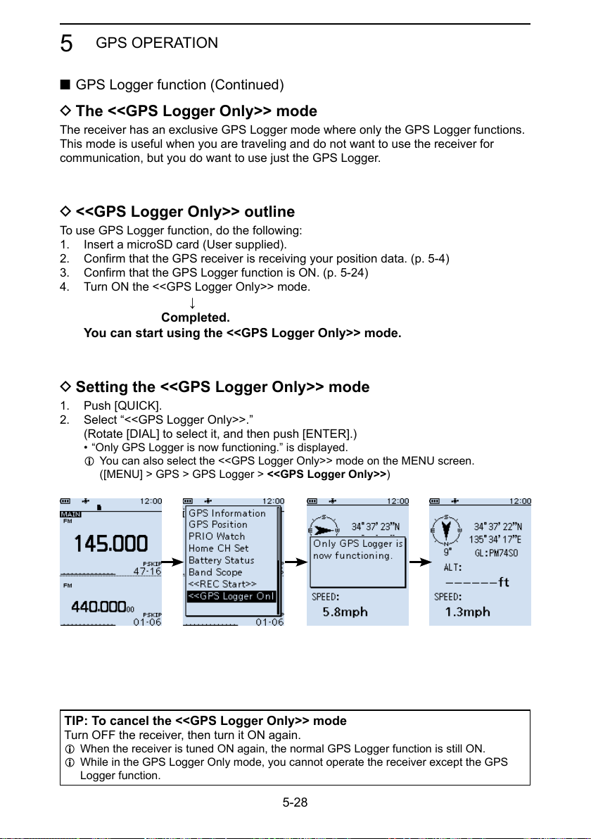
GPS OPERATION
5
■ GPS Logger function (Continued)
D The <<GPS Logger Only>> mode
The receiver has an exclusive GPS Logger mode where only the GPS Logger functions.
This mode is useful when you are traveling and do not want to use the receiver for
communication, but you do want to use just the GPS Logger.
D <<GPS Logger Only>> outline
To use GPS Logger function, do the following:
1. Insert a microSD card (User supplied).
2. Confirm that the GPS receiver is receiving your position data. (p. 5-4)
3. Confirm that the GPS Logger function is ON. (p. 5-24)
4. Turn ON the <<GPS Logger Only>> mode.
↓
Completed.
You can start using the <<GPS Logger Only>> mode.
D Setting the <<GPS Logger Only>> mode
1. Push [QUICK].
2. Select “<<GPS Logger Only>>.”
(Rotate [DIAL] to select it, and then push [ENTER].)
• “Only GPS Logger is now functioning.” is displayed.
L You can also select the <<GPS Logger Only>> mode on the MENU screen.
([MENU] > GPS > GPS Logger > <<GPS Logger Only>>)
TIP: To cancel the <<GPS Logger Only>> mode
Turn OFF the receiver, then turn it ON again.
L When the receiver is tuned ON again, the normal GPS Logger function is still ON.
L While in the GPS Logger Only mode, you cannot operate the receiver except the GPS
Logger function.
5-28

GPS OPERATION
5
■ GPS Logger function
D The <<GPS Logger Only>> mode (Continued)
The <<GPS Logger Only>> mode screen
Compass direction:
South Up
TIP:
• When GPS Logger is set to “OFF,” the a dialog is displayed.
(MENU > GPS > GPS Logger > GPS Logger)
To use the <<GPS Logger Only>> mode, select “YES.”
Latitude
Longitude
Grid locator
Altitude
Speed
• You can change the GPS Information, Grid Locator Display,
or Compass Direction settings.
In the <<GPS Logger Only>> mode, push [QUICK] to open
the Quick Menu window, and then select a setting item
you want to change.
5-29

MENU SCREEN
■ MENU screen................................................................ 6-2
D MENU screen operation ............................................ 6-2
D Selecting a Menu item ............................................... 6-3
■ Near Station .................................................................. 6-4
■ Scan .............................................................................. 6-4
■ Manage Memory ........................................................... 6-6
■ RX Recorder ................................................................. 6-7
■ GPS .............................................................................. 6-9
■ RX History ................................................................... 6-13
■ Digital Set.................................................................... 6-14
■ SPEECH ..................................................................... 6-16
■ Function ...................................................................... 6-18
■ Display ........................................................................ 6-22
■ Sounds ........................................................................ 6-27
■ Time Set ...................................................................... 6-29
■ Bluetooth Set .............................................................. 6-29
■ SD Card ...................................................................... 6-34
■ Others ......................................................................... 6-35
Section 6
6-1

MENU SCREEN
6
■ MENU screen
The MENU screen is displayed after pushing [MENU].
You can use the MENU screen to change settings.
MENU screen structure
D MENU screen operation
Opens the Quick Menu window.
Closes the
MENU screen.
Goes to the previous
Opens the MENU
screen Sets an option.
D-pad (Left)
tree level.
TIP: The MENU screen
is constructed in a tree
structure. You may go to
the next tree level, or go
back a level, depending on
the selected item.
D-pad (Up)
Selects an item
or option.
D-pad (Right)
Goes to the
next tree level.
D-pad (Down)
Selects an item
or option.
Simplied description—‘Select’ operation
In this manual, user’s ‘Select’ operation is simplied, as described below.
Simplied description: Select “Function,” and then push [ENTER].
Operation: Push D-pad (Up) or (Down) to select “Function,” and then
push [ENTER].
6-2

MENU SCREEN
6
D Selecting a Menu item
Example: Set “Auto Power OFF” to “30 min.”
[MENU] > Function > Auto Power OFF
1. Push [MENU].
2. Select “Auto Power OFF,” in the “Function” menu.
(Rotate [DIAL] to select it, and then push [ENTER].)
3. Select “30min,” and then push [ENTER].
• Sets the option, then goes back a tree level.
L Push [CLEAR] to return to the Main screen.
TIP: To return to the default setting
1. Push [QUICK] in step 3.
2. Select “Default,” and then push [ENTER].
• The setting returns to the default.
6-3

MENU SCREEN
6
■ Near Station
Near Station
[MENU] > Near Station
Displays nearest stations (
z Select a Memory channel, and then push [ENTER] to receive.
L Maximum of 50 stations are displayed.
NOTE:
• Conrm the “Internal GPS” is selected in the Menu screen.
([MENU] > GPS > GPS Set > GPS Select) (p. 6-12)
• “No Station Found” is displayed if there are no stations within 160 km.
• “GPS is invalid. Search by last valid position.” is displayed if previously received position data is valid.
• Memory channel, that is set as a SKIP or PSKIP channel, is excluded from the near station list.
within 160 km) saved in the Memory channel.
■ Scan
Pause Timer (Default: 10sec)
[MENU] > Scan > Pause Timer
Select the Scan Pause Timer. When receiving a signal, the scan pauses for this set period of time.
L Individually selectable for A band and B band.
• 2sec ~ 20sec: When a signal is received, the scan pauses for 2 ~ 20 seconds (in
• HOLD: The scan pauses on a received signal until the signal disappears.
2 second steps).
Resume Timer (Default: 2sec)
[MENU] > Scan > Resume Timer
Select the scan Resume Timer. When a received signal disappears, the scan resumes
after this set period of time passed.
L Individually selectable for A band and B band.
L The Duplex scan resumes after 200 milliseconds (xed) passed regardless of this setting.
• 0sec: The scan resumes immediately after the signal disappears.
• 1sec ~ 5sec: The scan resumes 1 ~ 5 seconds after the signal disappears.
• HOLD: The scan remains paused for the Pause Timer setting, even if the
NOTE: Rotate [DIAL] to resume the scan. The Resume Timer must be set shorter than
the Pause Timer, otherwise this timer does not work properly.
signal disappears.
Temporary Skip Timer (Default: 5min)
[MENU] > Scan > Temporary Skip Timer
Set the Temporary Skip Timer. The unwanted frequencies that are set as Skip channels
(PSKIP or SKIP) are skipped for this set period of time during a scan.
L This timer is activated for the VFO scan, and Memory scan.
L Individually settable for A band and B band.
• 5min/10min/15min: Skip channels are skipped for the set period of time.
• While Scanning: Skip channels are skipped until the Scan is stopped.
• While Powered ON: Skip channels are skipped until the receiver power is turned OFF.
6-4

MENU SCREEN
6
■ Scan (Continued)
Program Skip (Default: ON)
[MENU] > Scan > Program Skip
Turn the Program Skip Scan function ON or OFF for a VFO scan.
This function enables the receiver to skip the unwanted frequencies that are entered as a
Memory channel and is set to “PSKIP.”
L Individually settable for A band and B band.
• OFF: The receiver scans all frequencies.
• ON: The receiver does not scan frequencies set as “PSKIP” frequencies.
Group Link (Default:
[MENU] > Scan > Group Link
Select groups to be scanned during a Group Link Scan. The Group Link function scans
all channels in the selected groups.
Select a group, A ~ Z, and then push [ENTER] to turn the Link function ON or OFF.
L Displays “✔” when the function is set to ON.
L Individually selectable for A band and B band.
✔
for all groups)
P-Scan Edge
[MENU] > Scan > P-Scan Edge
You can delete, copy, or edit the lower and higher frequencies for programmed scans.
The receiver has a total of up to 50 frequency ranges (00 ~ 49), and you can set scan
name, tuning step, receive mode, and RF gain for each scan edge.
The default setting may differ, depending on the receiver version.
Program Link
[MENU] > Scan > Program Link
This item sets the link function for two or more program scan edge ranges to be
sequentially scanned during the Program Link Scan. The link function scans all
frequencies in the scan range.
Default settings of the Program Link:
Program Link
0:
Edit Name
1:
...
9:
Blank
00: 137.000- 174.000
Add
Delete
01: 400.000- 470.000
Program Link number
L When only one Program Scan Edge channel is entered, or there is no Programmed Scan
Edge is left, “Add” is not displayed after pushing [QUICK].
Program Scan Edge channel
6-5

MENU SCREEN
6
■ Scan (Continued)
Auto MW SCAN Memory Clear (Default: Display Dialog)
[MENU] > Scan > Auto MW SCAN Memory Clear
Select whether or not to delete “A:Auto MW” Channel contents when the auto memory
write scan starts.
• OFF: Does not delete “A:Auto MW” Channel contents when the auto
• Display Dialog: Displays the dialog to select whether or not to delete “A:Auto MW”
• ON: Deletes “A:Auto MW” Channel contents when the auto memory write
DUP Check During MR Scan (Default: OFF)
[MENU] > Scan > DUP Check During MR Scan
During a Memory scan, not only the set frequency, but also the offset frequency is
scanned if Duplex is set to the channel.
• OFF: Offset frequency is not scanned.
• ON: Offset frequency is also scanned.
memory write scan starts.
Channel contents when the auto memory write scan starts.
scan starts.
■ Manage Memory
[MENU] > Manage Memory
You can edit, copy, or delete groups and memory channels.
See section 4 for details.
6-6

MENU SCREEN
6
■ RX Recorder
<<REC Start>> / <<REC Stop>>
[MENU] > RX Recorder > <<REC Start>> / <<REC Stop>>
Select, and then push [ENTER] to start or stop recording.
L BE SURE to insert a microSD card.
L If you turned OFF the receiver without stop recording, the receiver automatically starts
recording when you turned ON next time.
Play Files
[MENU] > RX Recorder > Play Files
Displays saved voice data folders.
L BE SURE to insert a microSD card.
Playing back:
1. Select a folder that contains the file you want to playback, and then push [ENTER].
• The le list is displayed.
2. Select a file, and then push [ENTER].
• The VOICE PLAYER screen is displayed and starts playing back the audio.
L See page 3-4 for details.
3. Push [CLEAR] to stop playing.
• The le list is displayed.
L Push [CLEAR] again to return to the Main screen.
NOTE:
• You can playback an audio while recording.
• The folder name is automatically created, as shown below:
Recording date: 15th March 2018 (Folder name: 20180315)
• The le name is automatically created, as shown below:
Recording date and time: 15th March 2018 12:00:00 (File name: 20180315_120000A*)
* “A” stands for A band.
• The recorded audio is saved in wav format.
RX REC Condition (Default: Squelch Auto)
[MENU] > RX Recorder > Recorder Set > RX REC Condition
Select whether or not the squelch status affects the RX voice audio recording.
• Always: The receiver always records the RX voice audio regardless of the
• Squelch Auto: The receiver records the RX voice audio only when the squelch is
squelch status.
open.
L Recording continues for 2 seconds after the squelch is closed.
6-7

MENU SCREEN
6
■ RX Recorder (Continued)
File Split (Default: ON)
[MENU] > RX Recorder > Recorder Set > File Split
Turn the File Split function ON or OFF.
• OFF: The recored audio saved to a le, until its size exceeds 2 GB.
When the le size exceeds 2 GB, a new le is generated.
• ON:
File split conditions:
• 2 seconds have passed after the squelch is closed.
• When you change the operating mode (VFO, Memory or WX mode).
• When you change the receive frequency greater than 5 kHz (other than WFM mode) or
200 kHz (WFM mode), or when you input the frequency from the keypad.
• When you change the Memory channel.
• When you change the receive mode other than between FM and FM-N, AM and AM-N or
CW and CW-R.
• When you start a scan other than DUP scan or TONE scan.
• When or
frequency returns to the VFO frequency.
• After a signal is received during a VFO scan, when the receive frequency is changed greater
than 5 kHz (other than WFM mode) or 200 kHz (WFM mode) then a signal is received.
• After a signal is received during a Memory scan, when the channel is changed then a signal
is received.
• When a talk end code in the digital signal is received.
If the “RX REC Condition” is set to “Squelch Auto,” the file splits according to the
following split condition.
after a signal is received on a Priority channel during a Priority scan, when the receive
REC Operation (Default: A/B Link)
[MENU] > RX Recorder > Recorder Set > REC Operation
Select the recording operation on the dual band display.
• A/B Separate: The recording function is separately active/inactive on the selected
• A/B Link: The recording function is simultaneously active/inactive on both MAIN
band (MAIN band) when the function is started or stopped.
and SUB bands when the function is started or stopped.
L On the single band display, only displayed band (A or B) is recorded.
Skip Time (Default: 10sec)
[MENU] > RX Recorder > Player Set > Skip Time
Select the skip time to rewind or skip forward the recorded voice audio for this period of
time when you push the fast-rewind or fast-forward key during playback.
6-8

MENU SCREEN
6
■ GPS
GPS Information
[MENU] > GPS > GPS Information
Displays the GPS satellite direction, elevation, satellite number, and receiving status.
See page 5-14 for details.
GPS Position
[MENU] > GPS > GPS Position
Displays position data shown below. See page 5-4 for details.
L Rotate [DIAL] to change between MY, RX, MEM, and ALM screen.
• MY: My position
• RX: Received position
• MEM: GPS Memory position
• ALM: GPS Alarm position
GPS Memory
[MENU] > GPS > GPS Memory
You can save maximum of 300 position data, those come with GPS position or RX
history. See page 5-15 for details.
Alarm Select (Default: OFF)
[MENU] > GPS > GPS Alarm > Alarm Select
Select the target positions for the GPS Alarm function.
This function sounds alarm beeps when a target is in the active range.
See page 5-22 for details.
• OFF: Turns OFF the function.
• RX: The GPS Alarm sounds when a target (the last received position)
• Group: The GPS Alarm sounds when a target (positions in the GPS Memory,
• Memory: The GPS Alarm sounds when a target (the entered position in the
enters in your active alarm range.
or in the selected GPS Memory Group) enters in your active alarm
range.
GPS Memory) enters in the active alarm range.
6-9

MENU SCREEN
6
■ GPS (Continued)
Alarm Area (Group) (Default: 0.25')
[MENU] > GPS > GPS Alarm > Alarm Area (Group)
Set the GPS active alarm range.
When a target enters in this set active alarm range, the GPS Alarm sounds.
L When Alarm Select (p. 6-9) is set to “Group,” this setting is enabled.
Ranges differs, depending on the “Latitude/Longitude” setting.
([MENU] > Display > Display Unit > Latitude/Longitude)
• Latitude/Longitude = dddºmm.mm'
Ranges: 00.08' to 59.99' (0.01' steps)
• Latitude/Longitude = dddºmm'ss''
Ranges: 00'05'' to 59'59'' (0'01" steps)
Example:
When a target enters in the active alarm range, the GPS Alarm sounds and the GPS
alarm icon blinks.
Point A
Your location
Point B
0.25’ 0.25’
Point C
Sounds 3 beeps.
N
0.25’ 0.25’
6-10

MENU SCREEN
6
■ GPS (Continued)
Alarm Area (RX/Memory) (Default: Both)
[MENU] > GPS > GPS Alarm > Alarm Area (RX/Memory)
Select the GPS active alarm range.
When a target enters in the active alarm range, the GPS Alarm sounds and the GPS
alarm icon blinks.
L When Alarm Select (p. 6-9) is set to “RX” or “Memory,” this setting is enabled.
• Limited: The receiver sounds 3 beeps and the GPS Alarm icon blinks when
• Extended: The receiver sounds 3 beeps and the GPS Alarm icon blinks when
• Both: The receiver sounds a beep and the GPS Alarm icon blinks when the
When the target exits the 500 meter range, but is still in the
Example:
When a target station enters in the active alarm range (500 meter or 1 kilometer range,
depending on the setting), the GPS Alarm sounds.
Your location
the target enters the 500 meter range.
the target enters the 1 kilometer range.
target enters the 1 kilometer range, and sounds 3 beeps and the icon
blinks when it enters the 500 meter range.
1 kilometer range, the icon continues to blink, but no beeps sound.
Extended range
Approximately 1 km, 1094 Y
Limited range
Approximately 500 m, 547 Y
Target station
N
Sounds 3 beeps.Sounds a beep.
6-11

MENU SCREEN
6
■ GPS (Continued)
GPS Logger (Default: ON)
[MENU] > GPS > GPS Logger > GPS Logger
Turn the GPS Logger function ON or OFF.
This function logs the position, altitude, course, speed, and number of satellites being
used.
L BE SURE to insert a microSD card.
L When “GPS Select” is set to “OFF” or “Manual,” this function does not save the log.
TIP: The log data is saved on the microSD card. The le name is automatically created,
as shown below:
• Log start date and time: 20th May 2018 15:30:00
• File name: 20180520_153000.log
Record Interval (Default: 5sec)
[MENU] > GPS > GPS Logger > Record Interval
Set the GPS Logger function record interval to 1, 5, 10, 30, or 60 seconds.
Record Sentence (Default: ✔ for all sentences)
[MENU] > GPS > GPS Logger > Record Sentence
Set the GPS Logger function record sentence to RMC, GGA, VTG, or GSA.
L Displays “✔” when the sentence is set.
NOTE: Select at least one sentence, otherwise an error beep will sound.
<<GPS Logger Only>>
[MENU] > GPS > GPS Logger > <<GPS Logger Only>>
You can turn ON the GPS Logger Only mode ON. In this mode, only the GPS Logger is
functioning and the receiver does not receive signal.
L Information
• BE SURE to insert a microSD card.
• Set GPS Select to “Internal GPS.”
• To cancel the mode, restart the receiver.
GPS Select (Default: Internal GPS)
[MENU] > GPS > GPS Set > GPS Select
Select how to capture position data.
• OFF: A GPS receiver is not used.
• Internal GPS: Position data of the internal GPS data is used for the GPS functions.
• Manual: Manually enter the current Latitude, Longitude, and Altitude in Manual
Position.
6-12

MENU SCREEN
6
■ GPS (Continued)
Power Save (Internal GPS) (Default: Auto)
[MENU] > GPS > GPS Set > Power Save (Internal GPS)
Select whether or not to use the Power Save function for the internal GPS receiver.
When this function is ON, and if the GPS receiver does not receive signals from a
satellite for 5 minutes, the function turns OFF the GPS receiver for this set period of time.
• OFF: The GPS receiver is always turned ON.
• 1, 2, 4, 8min: When the receiver cannot receive signals from a satellite for 5
• Auto: When the receiver cannot receive signals from a satellite for 5
minutes, the GPS receiver is turned OFF for the selected period of
time. (1, 2, 4, or 8 minutes). After this period, the receiver resumes
receiving.
minutes, the GPS receiver is turned OFF for 1 minute. After this
period, the receiver resumes receiving. The Power Save interval time
extends to 2, 4, and then 8 minutes when receiving no signals for
another 5 minutes, respectively.
Manual Position
[MENU] > GPS > GPS Set > Manual Position
Manually enter the latitude, longitude, and Altitude of your current position.
(Default: Latitude:0°00.00'N/Longitude:0°00.00'E/Altitude:------ft)
■ RX History
[MENU] > RX History
When a call is received in a digital mode, the call information such as the caller station’s
call sign or the repeater’s call sign are saved on this screen. Up to 50 records can be
saved.
L When you receive the 51th call, the oldest history will be deleted.
L Even if the receiver is turned OFF, the saved records are not deleted.
TIP: To display the RX record contents
On the RX HISTORY screen, rotate [DIAL] to display the RX record contents (RX01 ~
RX50).
6-13

MENU SCREEN
6
■ Digital Set
Bass (Default: Normal)
[MENU] > Digital Set > Tone Control > D-STAR/P25/dPMR/NXDN/DCR > Bass
Select the audio bass lter level.
• Cut: Reduces the low frequencies.
• Normal: Normal tone balance.
• Boost: Increases the low frequencies.
Treble (Default: Normal)
[MENU] > Digital Set > Tone Control > D-STAR/P25/dPMR/NXDN/DCR > Treble
Select the audio treble lter level.
• Cut: Reduces the high frequencies.
• Normal: Normal tone balance.
• Boost: Increases the high frequencies.
Bass Boost (Default: OFF)
[MENU] > Digital Set > Tone Control > D-STAR/P25/dPMR/NXDN/DCR > Bass Boost
Turn the Audio Bass Boost function ON or OFF.
• OFF: Turns OFF the function.
• ON: This function boosts the audio bass.
Digital Monitor (Default: Auto)
[MENU] > Digital Set > Digital Monitor
Select a Receive mode when you push [SQL] in the Digital mode.
• Auto: Receives in the digital mode or the analog mode, depending on the
• Digital: Monitors in the digital mode. (Forcibly opens the Digital Code
• Analog: Monitors in the analog mode.
RX History Log (Default: OFF)
[MENU] > Digital Set > RX Log > RX History Log
Select whether or not to make a Digital mode’s receive history log on a microSD card.
The log is saved in the csv format.
L BE SURE to insert a microSD card.
• OFF: Turns OFF the function.
• ON: The receiver makes a history log on the microSD card.
received signal.
squelch)
6-14

MENU SCREEN
6
■ Digital Set (Continued)
Separator/Decimal (Default: Sep [,] Dec [.])
[MENU] > Digital Set > RX Log > CSV Format > Separator/Decimal
Select the separator and decimal character for the csv format.
• Sep [,] Dec [.]: Separator is “,” and Decimal is “.”
• Sep [;] Dec [.]: Separator is “;” and Decimal is “.”
• Sep [;] Dec [,]: Separator is “;” and Decimal is “,”
Date (Default: mm/dd/yyyy)
[MENU] > Digital Set > RX Log > CSV Format > Date
Select the separator and decimal character for the csv format.
Select the date format between “yyyy/mm/dd,” “mm/dd/yyyy,” and “dd/mm/yyyy.”
(y: year, m: month, d: day)
RX Record (D-STAR RPT) (Default: ALL)
[MENU] > Digital Set > RX Record (D-STAR RPT)
The receiver can record the data of up to 50 individual calls. When the received signal
includes a status message (“UR?” or “RPT?”) that is sent back from the Access repeater,
you can record up to 50 messages, or only the last call, in the Received Call Record.
• ALL: Records up to 50 calls.
• Latest Only: Records only the last call.
D-STAR EMR AF Level (Default: 19)
[MENU] > Digital Set > D-STAR EMR AF Level
Set the audio output level to between 0 and 39 for when an EMR communication signal
is received. When an EMR signal is received, the audio is heard at this set level, or the
volume control level, whichever is higher.
To disable the setting, set to “0.”
NOTE: After an EMR signal disappears, the audio level will remain at the EMR level. In
this case, adjust the audio level.
Fast Unmute (NXDN) (Default: ON)
[MENU] > Digital Set > Fast Unmute (NXDN)
Selects the mute state for the Encryption function in the NXDN mode.
This function releases the mute without conrming whether or not the encryption key
matches. If you want to prevent cutting off the beginning of the received audio, set to
“ON.”
• OFF: Releases the mute after conrming the encryption key matches.
• ON: Releases the mute without conrming whether or not the encryption key
matches.
6-15

MENU SCREEN
6
■ SPEECH
D-STAR RX Call Sign SPEECH (Default: ON (Kerchunk))
[MENU] > SPEECH > D-STAR RX Call Sign SPEECH
Turn the RX Call Sign Speech function ON or OFF for a signal received in the D-STAR
mode.
L Information
• When the Digital Squelch function is used, the calling station’s call sign is not
announced if the received signal is not addressed, or does not include a matching
digital code.
• When you receive a signal from a repeater (“UR?” or “RPT?”), the caller station’s call
sign is not announced.
• While scanning, the receiver resumes the scan during an announcement.
• Even if a note is entered after the call sign, it is not announced.
• When you receive a signal during an announcement, the receiver cancels the
announcement, and you can hear the received audio.
• OFF: The caller station’s call sign is not announced, even when a call is
• ON (Kerchunk): The caller station’s call sign is announced only when they make a
• ON (All): The caller station’s call sign is always announced.
DIAL SPEECH (Default: OFF)
[MENU] > SPEECH > DIAL SPEECH
Turn the Dial Speech function ON or OFF. The Dial Speech function announces the
frequency that is selected by rotating [DIAL].
L When you receive a signal during an announcement, the receiver cancels the
announcement, and you can hear the received audio.
• OFF: The frequency is not announced.
• ON: The frequency is announced, 1 second after rotating [DIAL].
received.
short transmission.
6-16
MENU SCREEN
6
■ SPEECH (Continued)
MODE SPEECH (Default: OFF)
[MENU] > SPEECH > MODE SPEECH
Turn the Receive Mode Speech function ON or OFF.
When this function is ON, the selected receive mode is announced.
L While the VFO scanning, the receive mode is announced when you change the mode.
• OFF: The selected receive mode is not announced.
• ON: The selected receive mode is announced.
SPEECH Language (Default: English)
[MENU] > SPEECH > SPEECH Language
Set the speech language to English or Japanese.
Alphabet (Default: Normal)
[MENU] > SPEECH > Alphabet
Select either “Normal” or “Phonetic Code” to announce the alphabet characters.
• Normal: Normal code is used.
(Example: A as eh, B as bee)
• Phonetic Code: The Phonetic code is used.
(Example: A as Alfa, B as Bravo)
SPEECH Speed (Default: Fast)
[MENU] > SPEECH > SPEECH Speed
Set the speech speed to Slow or Fast.
SPEECH Level (Default: 5)
[MENU] > SPEECH > SPEECH Level
Adjust the voice synthesizer volume level to between 0 (OFF), 1 (minimum), and
9 (maximum).
6-17

MENU SCREEN
6
■ Function
Auto Power OFF (Default: OFF)
[MENU] > Function > Auto Power OFF
Select whether or not to automatically turn OFF the receiver after inactivity for this set
period of time.
L “AUTO POWER OFF” is displayed and beeps sound 5 seconds before turning OFF the
receiver. If you operate the receiver during this period of time, the Auto Power OFF timer is
reset.
• OFF: Does not turn OFF the receiver.
• 30/60/90/120min: Turns OFF the receiver after inactivity for this set period of time.
• No Signal: The receiver will turn OFF when no signal is continuously received for
Power Save (Default: Auto (Short))
[MENU] > Function > Power Save
Set the Power Save function to reduce current drain and conserve battery power.
When the Power Save function is activated, the call sign or the beginning of the signal
may not be received correctly.
• OFF: Turns OFF the function.
• Auto (Short): This function is activated in a 1:3 ratio (10 milliseconds:
• Auto (Middle): This function is activated in a 1:3 ratio (10 milliseconds:
*
• Auto (Long): This function is activated in a 1:3 ratio (10 milliseconds:
*
NOTE: The Power Save function is disabled when using an external power source, or
if the receiving mode is set to LSB, USB, CW, or CW-R.
Standby
3 minutes.
30 milliseconds) when no signal is received for 5 seconds.
30 milliseconds) when no signal is received for 5 seconds.
1
The ratio becomes 1:10 (10 milliseconds: 100 milliseconds) when
no signal is received for another 30 seconds.
30 milliseconds) when no signal is received for 5 seconds.
2
The ratio becomes 1:30 (10 milliseconds: 300 milliseconds) when
no signal is received for another 30 seconds.
10 milliseconds 10 milliseconds 10 milliseconds
OFF
5 seconds of
no signal
30 milliseconds
30 seconds 30 seconds
1
*
6-18
2
*

MENU SCREEN
6
■ Function (Continued)
Monitor (Default: Push)
[MENU] > Function > Monitor
Select an option for the [SQL] Monitor function. (BASIC MANUAL Section 3)
• Push: Hold down [SQL] to monitor the frequency. Release to stop
• Hold: Push [SQL] momentarily to monitor the frequency and push
Dial Speed-UP (Default: ON)
[MENU] > Function > Dial Speed-UP
Turn the Dial Speed Acceleration ON or OFF. The acceleration automatically speeds up
the tuning dial speed when you rapidly rotate [DIAL].
• OFF: Turns OFF the function.
• ON: Turns ON the function.
Key Lock (Default: Normal)
[MENU] > Function > Key Lock
Select the key lock type when the Key Lock function is ON.
• Normal: All keys and dials except [SQL] and [VOL] are locked.
• No SQL: All keys and dials except [SQL] is locked.
• No VOL: All keys and dials except [VOL] is locked.
• ALL: All keys and dials are locked.
monitoring.
momentarily again to cancel it.
Active Band (Default: All)
[MENU] > Function > Active Band
Enables continuous frequency selection of the receive frequency across all bands using
[DIAL].
L This setting does not affect the scan.
• Single: When you change the frequency on the band edge, the top or bottom
• ALL: When you change the frequency, the next band is displayed.
Set the selectable frequencies on the receiver to all bands for
frequency in the displayed band is selected.
continuous selection.
Bar Antenna (Default: Use)
[MENU] > Function > Bar Antenna
Select whether or not to use the internal bar antenna to receive the AM broadcast band
(0.495 ~ 1.620 MHz).
L The Attenuator does not work, when using the bar antenna (BASIC MANUAL Section 3).
• Not used: Does not use the internal bar antenna.
• Use: Uses the internal bar antenna. (The bar antenna is used for only the
AM broadcast band.)
6-19

MENU SCREEN
6
■ Function (Continued)
Earphone Antenna ( ~ 1.3G) (Default: Not Used)
[MENU] > Function > Earphone Antenna ( ~ 1.3G)
Select whether or not to use the earphone cable connected to the receiver as an
antenna.
• Not Used: Does not use the earphone cable as an antenna.
• Use: Uses the earphone cable as an antenna.*
CI-V Address (Default: 9C)
[MENU] > Function > CI-V > CI-V Address
To distinguish equipment, each CI-V receiver or transceiver has its own Icom standard
address in hexadecimal code. The receiver’s default address is 9C.
When 2 or more receivers are controlled through a PC at the same time, set a different
address for each receiver.
CI-V Baud Rate (Default: Auto)
[MENU] > Function > CI-V > CI-V Baud Rate
Set the CI-V data transfer speed to 4800, 9600, 19200 bps, or Auto.
L When “Auto” is selected, the baud rate is automatically set, according to the data rate of
the controller.
*The external antenna is also used.
CI-V Transceive (Default: OFF)
[MENU] > Function > CI-V > CI-V Transceive
Turn the CI-V Transceive function ON or OFF.
OFF: Turns OFF the function.
ON: When you change a setting on one receiver, the same settings is automatically
changed on other connected transceivers or receivers.
CI-V USB/Bluetooth -> REMOTE Transceive Address (Default: 00)
[MENU] > Function > CI-V > CI-V USB/Bluetooth -> REMOTE Transceive Address
Set the address.
If you remotely operate using a USB cable or Bluetooth when CI-V Transceive is set
to “ON,” the device in the same system is externally controlled through the Speaker
(REMOTE) jack.
Enter an address between 00 and DF (hexadecimal).
L Set other address than “00” to prohibit the external control by a third-party receiver.
L The control signal is output from the [SP] jack.
6-20

MENU SCREEN
6
■ Function (Continued)
USB Connect (Default: Serialport)
[MENU] > Function > USB Connect
Select the mode when connecting the receiver to a PC with a USB cable.
• Charge Only: You can only charge the receiver using a USB cable.
• Serialport: You can program the receiver, output D-STAR data, GPS information,
• SD Card Mode*: You can transfer the les between the inserted microSD card and a
*A conrmation dialog is displayed.
TIP: Application setting to output D-STAR data:
Congure the communication software as follows.
• Port: COM port number that is used by the receiver.*
• Baud rate: 4800/9600 bps
• Data bit: 8 bit
• Parity: none
• Stop bit: 1 bit
• Flow control: Xon/Xoff
* Depending on the PC environment, the COM port number used by the receiver may
be higher than 5. In that case, use an application that can set it to higher than 5.
NOTE:
• Conrm that the “Internal GPS” is selected, when you output the received position
data.
([MENU] > GPS > GPS Set > GPS Select)
• While in the SD Card Mode, the receiver works not as a receiver but as a data storage
device. It temporarily stops recording and logging.
and remotely control the receiver using the CI-V commands.
PC, using an USB cable.
TIP: Removing the receiver in the SD card mode
1. Click “
2. Confirm “Safe To Remove Hardware” is displayed, and then remove the USB cable
from the PC.
,” and then click “Eject IC-R30.”
6-21

MENU SCREEN
6
■ Function (Continued)
USB Serialport Function (Default: CI-V (Echo Back OFF))
[MENU] > Function > USB Serialport Function
Set the Serialport function for the USB connection to data device, PC and so on.
• CI-V (Echo Back OFF): The CI-V command is input or output through the USB port.
Does not send back the CI-V command input from the USB
• CI-V (Echo Back ON): The CI-V command is input or output through the USB port.
Sends back the CI-V command input from the USB port.
• D-STAR Data: The D-STAR data is output to the USB port.
• GPS Out: The GPS information from the internal GPS receiver is
port.
output to the USB port.
■ Display
Backlight (Default: Auto (DC IN: ON))
[MENU] > Display > Backlight
Select an option for the receiver backlight.
• OFF: The backlight does not light.
• ON: The backlight lights continuously.
• Auto: The backlight lights when you push a key or rotate [DIAL], and
• Auto (DC IN: ON): The backlight lights when you push a key or rotate [DIAL], and
* When using the GPS logger, or an external DC power source is
goes out after the set period of time in the Backlight Timer.
goes out* after the set period of time in the Backlight Timer.
connected, “Auto (DC IN: ON)” is automatically selected.
Backlight Timer (Default: 5sec)
[MENU] > Display > Backlight Timer
Set the Backlight Timer to 5 or 10 seconds. Depending on the Backlight option, the
backlight lights for this set period of time, and then automatically goes out.
LCD Dimmer (Default: Bright)
[MENU] > Display > LCD Dimmer
Set the LCD backlight brightness level.
• Bright: The LCD backlight brightness level is bright.
• Dark: The LCD backlight brightness level is dim.
6-22

MENU SCREEN
6
■ Display (Continued)
LCD Contrast (Default: 5)
[MENU] > Display > LCD Contrast
Set the LCD Contrast level to between 1 (the lowest) and 10 (the highest).
RX Popup (Default: Normal)
[MENU] > Display > RX Popup
Select whether or not to display the pop-up when you receive a digital signal.
• OFF: The pop-up is not displayed.
• Normal: When the Digital signal is received, the call sign or ID of FROM/TO
• RX Hold: While receiving the Digital signal, the call sign or ID of FROM/TO
• Hold: When the Digital signal is received, the call sign or ID of FROM/TO
P25 RX ID Display (Default: Dec)
[MENU] > Display > P25 RX ID Display
Set the display format of the received ID in the P25 mode to decimal number (Dec) or
hexadecimal number (Hex).
stations are displayed for 3 seconds.
stations are displayed until any key is pushed or [DIAL] is rotated.
stations are displayed until any key is pushed or [DIAL] is rotated.
RX Backlight (Default: Digital Mode)
[MENU] > Display > RX Backlight
Select an option for the RX Backlight function.
This function turns ON the backlight when receiving a signal and the audio signal is output.
• OFF: The function is OFF.
• Digital Mode: The backlight automatically lights when displaying the calling station's call
• ALL: The backlight automatically lights when receiving a signal, or while displaying
NOTE:
• The function is enabled only when the “Backlight” is set to “Auto” or
“Auto (DC IN: ON).” ([MENU] > Display > Backlight)
• The backlight lights even if the function is OFF, when the “Backlight” is set to “ON” or
“Auto (DC IN: ON).”
• The backlight automatically turns OFF, according to the “Backlight Timer” (p. 6-22)
setting.
sign or ID, or a received message on the display in the Digital mode.
L If the message is repeatedly displayed, the backlight does not light.
the calling station’s call sign or ID, or a received message on the display.
6-23
 Loading...