

Page 1
INSTRUCTION MANUAL
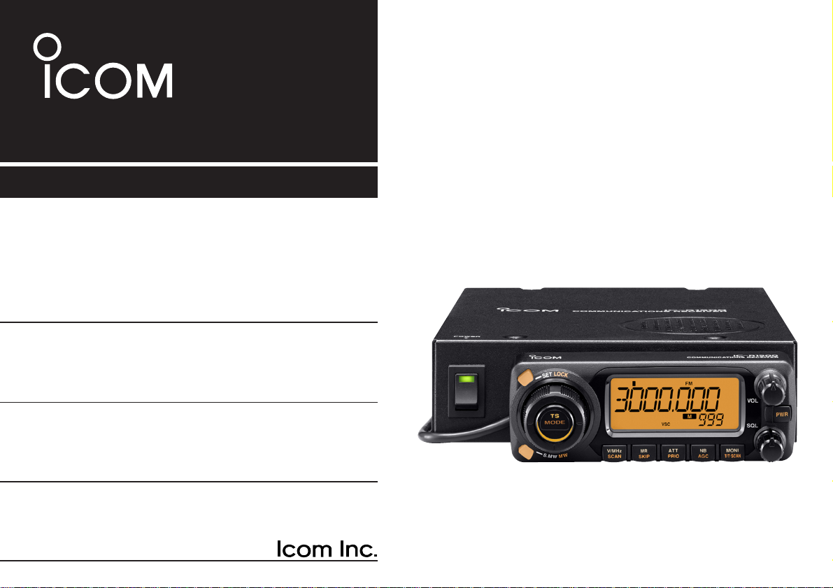
iR1500
COMMUNICATIONS RECEIVER
Page 2
i
FOREWORD
Thank you for purchasing this Icom receiver. The IC-R1500
COMMUNICATIONS RECEIVER
is designed and built with Icom’s
state of the art technology and craftsmanship. With proper
care, this receiver should provide you with years of troublefree operation.
We want to take a couple of moments of your time to thank
you for making the IC-R1500 your radio of choice, and hope
you agree with Icom’s philosophy of “technology first.” Many
hours of research and development went into the design of
your IC-R1500.
DD
FEATURES
❍ Wide frequency coverage with all-mode re-
ceive
❍ Both Remote controller operation and PC
control application are available
❍
ANF and NR functions are available (Only
when the optional DSP unit is installed.)
❍ IF shift function
IMPORTANT
READ ALL INSTRUCTIONS carefully and completely
before using the receiver.
SAVE THIS INSTRUCTION MANUAL— This in-
struction manual contains important operating instructions for
the IC-R1500.
EXPLICIT DEFINITIONS
WORD DEFINITION
R WARNING!
CAUTION
NOTE
Personal injury, fire hazard or electric shock
may occur.
Equipment damage may occur.
Recommended for optimum use. No risk of
personal injury, fire or electric shock.
Icom, Icom Inc. and the logo are registered trademarks of Icom Incorporated (Japan) in the United States, the United Kingdom, Germany, France,
Spain, Russia and/or other countries.
Page 3

ii
RWARNING! NEVER connect the receiver via the
OPC-254L to an AC outlet. This may pose a fire hazard or result in an electric shock.
RWARNING! NEVERoperate the receiver while dri-
ving a vehicle. Safe driving requires your full attention— anything less may result in an accident.
NEVER connect the receiver to a power source of more
than 14 V DC. This will damage the receiver.
NEVER connect the receiver to a power source using re-
verse polarity. This will damage the receiver.
NEVER cut the DC power cable between the DC plug and
fuse holder. If an incorrect connection is made after cutting,
the receiver may be damaged.
DO NOT leave the main unit powered ON and connected
to a vehicle’s electrical system. The main unit draws approx.
550 mA. This will eventually drain the vehicle’s battery.
NEVER expose the receiver to rain, snow or any liquids.
The receiver may be damaged.
NEVERoperate or touch the receiver with wet hands. This
may result in an electric shock or damage the receiver.
NEVER place the receiver where normal operation of the
vehicle may be hindered or where it could cause bodily injury.
NEVERlet objects impede the operation of the cooling fan
on the rear panel.
AVOID using or placing the receiver in direct sunlight or in
areas with temperatures below –10°C (+14°F) or above
+60°C (+140°F).
BE CAREFUL! The receiver will become hot when op-
erating it continuously for long periods.
AVOID setting the receiver in a place without adequate
ventilation. Heat dissipation may be affected, and the receiver
may be damaged.
AVOID the use of chemical agents such as benzine or al-
cohol when cleaning, as they can damage the receiver’s surfaces.
For U.S.A. only
CAUTION: Changes or modifications to this device, not ex-
pressly approved by Icom Inc., could void your authority to
operate this device under FCC regulations.
PRECAUTIONS
Page 4
iii
TABLE OF CONTENTS
FOREWORD ........................................................................................... i
IMPORTANT ............................................................................................ i
EXPLICIT DEFINITIONS ......................................................................... i
PRECAUTIONS ...................................................................................... ii
SUPPLIED ACCESSORIES .................................................................. iii
SPECIFICATIONS ................................................................................. iii
TABLE OF CONTENTS ......................................................................... iii
OPTIONS ............................................................................................... iv
1 CONNECTION .............................................................................. 1–2
■ Rear panel connection.................................................................... 1
■ Antenna installation ........................................................................2
2PANEL DESCRIPTION ................................................................. 3–7
■ Front panel—controller .................................................................. 3
■ Function display—controller ...........................................................5
■ Rear panel—main unit ................................................................... 7
3 SETTING A FREQUENCY .......................................................... 8–10
■ Turning power ON/OFF ................................................................. 8
■ Mode selection ............................................................................... 8
■ Tuning step selection ..................................................................... 9
■ Setting a frequency ........................................................................ 9
■ Receive mode selection ............................................................... 10
4 BASIC OPERATION ................................................................. 11–15
■ Receiving ..................................................................................... 11
■ Monitor function ............................................................................11
■ Lock function ................................................................................ 11
■ Attenuator function........................................................................ 12
■ NB function .................................................................................. 12
■ AGC function ................................................................................12
SPECIFICATIONS
Specifications are provided in the IC-PCR1500/IC-PCR2500’s
Instruction manual.
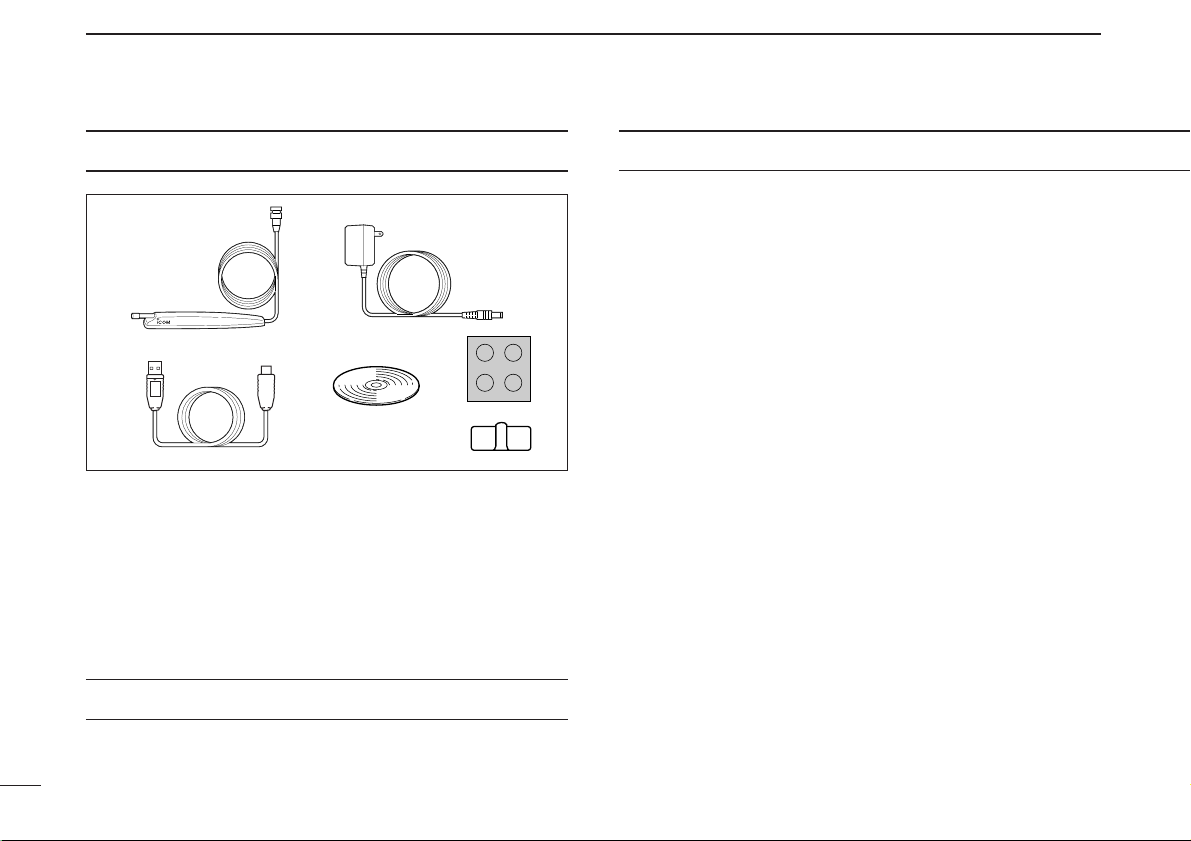
SUPPLIED ACCESSORIES
q Antenna …………………………………………………… 1
w AC adapter* ……………………………………………… 1
e USB cable ………………………………………………… 1
r CD ………………………………………………………… 1
t Foot pad sheet……………………………………………… 1
y Cable hanger ……………………………………………… 1
*Not supplied with some versions.
y
t
re
qw
Page 5

iv
1
2
3
4
5
6
7
8
9
10
11
12
13
14
15
16
■ AFC function ................................................................................ 13
■ VSC function ................................................................................ 13
■ IF filter selection ........................................................................... 14
■ IF shift function .............................................................................14
■ Duplex operation .......................................................................... 15
5 MEMORY OPERATION ............................................................ 16–24
■ General description ...................................................................... 16
■ Memory channel selection ........................................................... 16
■ Programming a memory channel ................................................. 17
■ Programming channel names ..................................................... 18
■ Copying memory contents ........................................................... 19
■ Memory clearing .......................................................................... 21
■ Memory bank setting ....................................................................22
■ Memory bank selection ................................................................ 23
■ Transferring bank contents .......................................................... 23
6 SCAN OPERATION .................................................................. 25–29
■ Scan types ................................................................................... 25
■ Scan start/stop ............................................................................. 26
■ Scan edges programming ............................................................ 27
■ Skip scan ..................................................................................... 28
■ Scan resume condition ................................................................ 29
7 PRIORITY WATCH .......................................................................... 30
■ Priority watch types ...................................................................... 30
■ Priority watch operation ............................................................... 30
8 POCKET BEEP AND TONE SQUELCH ................................... 31–34
■ Pocket beep operation ................................................................. 31
■ Tone/DTCS squelch operation ..................................................... 33
■ Tone scan ..................................................................................... 34
9 SET MODE ................................................................................ 35–43
■ General ........................................................................................ 35
■ Set mode items ............................................................................ 35
10 OTHER FUNCTIONS ................................................................ 44–48
■ Weather channel operation .......................................................... 44
■ DSP operation ..............................................................................45
■ DATAcloning ................................................................................ 46
■ Partial reset................................................................................... 47
■ All reset......................................................................................... 47
■ Internal audio switch..................................................................... 48
11 TROUBLESHOOTING .................................................................... 49
12 DOC................................................................................................. 50
OPTIONS
UT-106*
DSP UNIT
Provides AF DSPfunctions such as noise reduction and auto notch.
CP-12L
CIGARETTE LIGHTER CABLES
For operation and charging via a 12 V cigarette lighter socket.
OPC-254L
DC POWER CABLES
For operation and charging via an external power supply.
SP-10
EXTERNAL SPEAKER
For all-round mobile operation. Cable length: 1.5 m; 4.9 ft
OPC-1156
SEPARATION CABLE
For extended separate installation. 3.5 m; 11.5ft
*: UT-106 installation is described in the IC-PCR1500/IC-PCR2500’s
Instruction manual.
Page 6
1
CONNECTION
1
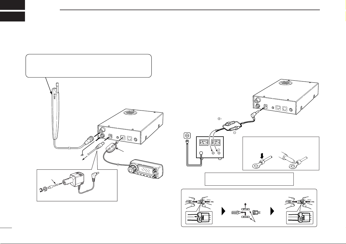
■ Rear panel connection
D DC power supply connection
Use a 12 V DC power supply with at least 4 Acapacity.
Make sure the ground terminal of the DC power supply is
grounded.
• CONNECTING TO ADC POWER SUPPLY
OPC-254L
(optional)
black
white
R CAUTION! NEVER remove the fuse-
holders from the DC power cable.
Connect to a 12 V DC
battery. Pay attention
to polarities. NEVER
connect to a 24 V battery. This could damage the receiver.
Solder
Crimp
NOTE: Use the terminals as shown
below for the cable connections.
D Fuse replacement
Receiver
Fuses (4 A)
DC power
supply 12 V
to an
AC outlet
−⊕
Ferrite core
Controller
CP-12L
(optional)
To a cigarette lighter socket
Fuse (4 A)
Or
Receiver
To ground
Supplied antenna
The antenna holder is backed with double-sided
tape. Remove the protective paper when the
antenna is fixed to any place.
To AC adapter
Page 7
2
1
CONNECTION
1
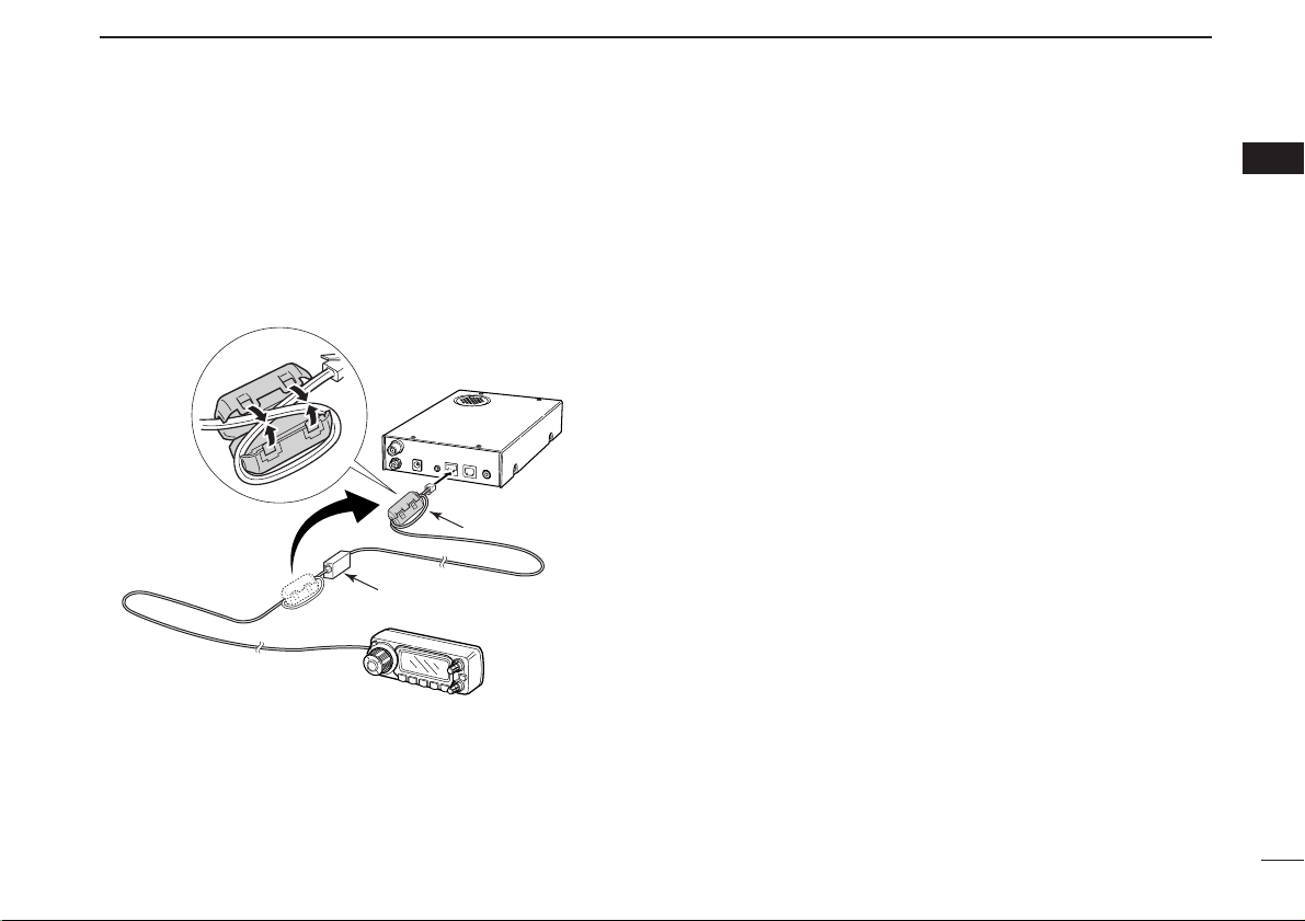
DD
OPC-1156 connection
q Connect the controller plug to the OPC-1156 jack.
w Detach the ferrite core from the controller cable, then at-
tach it to the OPC-1156 as shown below.
• Make sure to wind the cable on the ferrite core.
e Connect the OPC-1156 plug to the [CONTROLLER] con-
nector of the receiver.
■ Antenna installation
D Antenna location
To obtain maximum performance from the receiver, select a
high-quality antenna and mount it in a good location. It is not
necessary to use radials on a magnetic mount (“mag mount”)
antenna.
Receiver
OPC-1156
Controller
Jack
Ferrite core
Page 8
3
PANEL DESCRIPTION
2
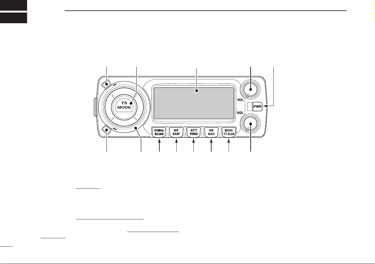
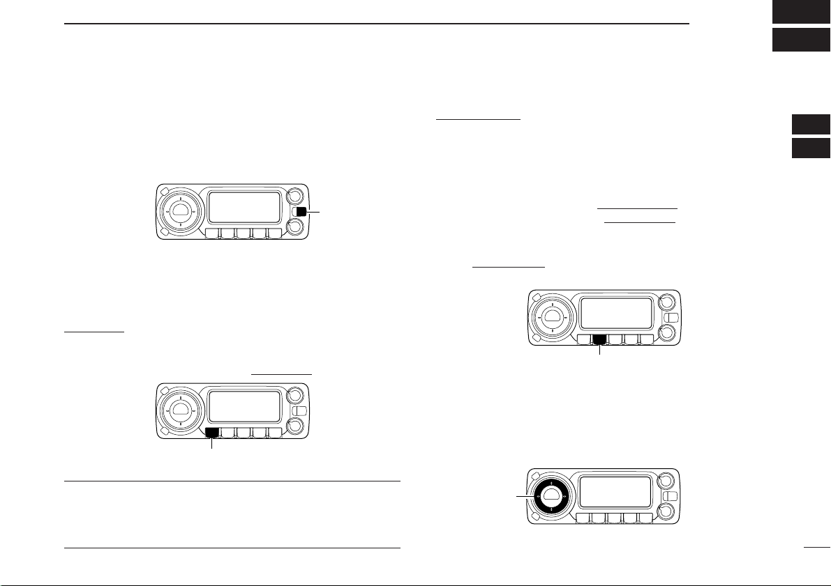
q SET•LOCK KEY [SET•LOCK]
➥ Push to enter set mode
. (p. 35)
➥ Push and hold for 1 sec. to turn the lock function ON
and OFF. (p. 11)
w TUNING STEP/MODE KEY [TS•MODE]
➥ Push to enter tuning step selection mode
. (p. 9)
• Rotate [DIAL] to select the desired tuning step.
➥ Push and hold for 1 sec. to enter receive mode selec-
tion mode. (p. 10)
• Rotate [DIAL] to select the desired operating mode.
e VOLUME CONTROL [VOL] (p. 11)
Adjusts the audio level.
r POWER KEY FOR CONTROLLER [PWR]
Push to turn the controller power ON when it’s OFF.
• Push and hold for 1 sec. to turn the controller power OFF when
it’s ON.
t SQUELCH CONTROL [SQL]
Varies the squelch level. (p. 11)
■ Front panel—controller
Function display (p. 5)
L
T
O
E
C
S
K
S
.
W
M
M
W
!2 !1 !0 oiuy t
rewq
Page 9
4
2
PANEL DESCRIPTION
2
y MONITOR•TONE•TONE SCAN KEY [MONI•T/T-SCAN]
➥ Push to turn the monitor function ON and OFF. (p. 11)
➥ Push and hold for 1 sec. to enter tone squelch selection
mode. (pgs. 31, 33)
•Tone squelch, pocket beep (CTCSS), tone squelch reverse
action, DTCS squelch, pocket beep (DTCS), DTCS squelch
reverse action or tone function OFF can be selected.
➥ Push and hold for 1 sec. during tone squelch selection
mode to start the tone scan. (p. 34)
u NOISE BLANKER/AUTOMATIC GAIN CONTROL KEY
[NB•AGC]
➥ Push to turn the NB (Noise Blanker) function ON and
OFF. (p. 12)
• The noise blanker function cannot be used in FM/WFM modes.
➥ Push and hold for 1 sec. to select the AGC (Automatic
Gain Control) function Slow and Fast. (p. 12)
While in FM or WFM mode, the AGC function is fixed
as Fast and AGC Slow cannot be selected.
i ATTENUATOR/PRIORITY KEY [ATT•PRIO]
➥ Push to turn the A TT(Attenuator) function ON and OFF.
(p. 12)
➥ Starts priority watch when pushed and held for 1 sec.
(p. 30)
o MEMORY/SKIP KEY [MR•SKIP]
➥ Push to select the memory channel, memory bank or
weather channel* modes. (pgs. 16, 23, 44)
*Weather channels are available for USA/CANADA versions
only.
➥ Push and hold for 1 sec. to turn the channel skip setting
ON and OFF for memory/frequency skip scan operation.
(p. 28)
!0 VFO/MHz TUNING•SCAN KEY [V/MHz•SCAN]
➥ Selects and toggles VFO mode
and band selection,
1 MHz or 10 MHz tuning when pushed. (p. 9)
➥ Starts scan when pushed and held for 1 sec. (p. 26)
• Cancels a scan when pushed during scan.
!1 TUNING DIAL [DIAL]
Selects the operating frequency (p. 9), memory channel
(p. 16), the setting of the set mode item (p. 35) and the
scanning direction (p. 26).
!2 MEMORY WRITE KEY [S.MW•MW] (pgs. 17, 18, 21)
➥ Selects a memory channel for programming when
pushed.
➥ Programs the selected memory channel when pushed
and held for 1 sec.
!3 POWER SWITCH FOR RECEIVER [POWER]
Turns the receiver power ON and OFF.
!3
Page 10
5
2
PANEL DESCRIPTION
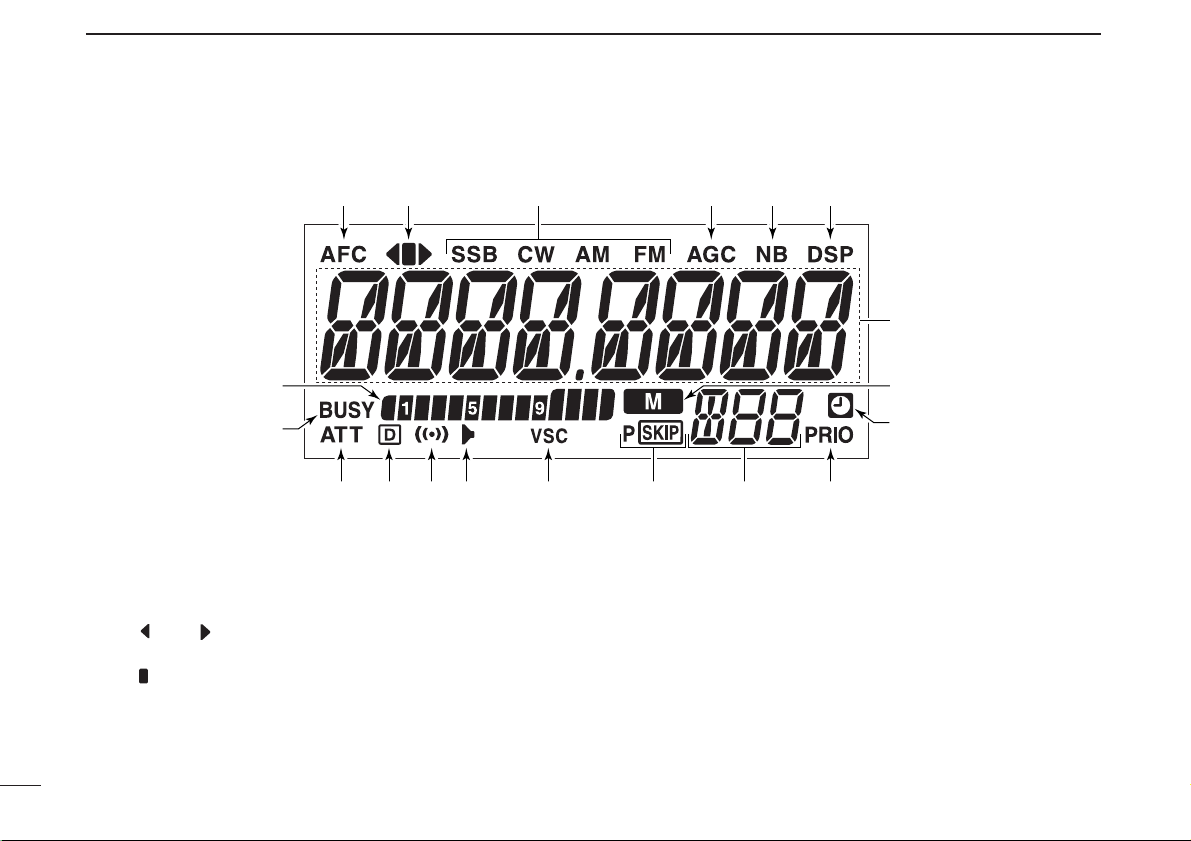
qAFC INDICATOR
Appears when the AFC function is in use. (p. 13)
wFM CENTER INDICATORS
➥ “” or “ ” appears when the received signal is not
tuned to its center frequency; or the squelch is closed.
➥ “” appears when the received signal is tuned to its
center frequency.
eRECEIVE MODE INDICATORS
Shows the selected receive mode.
• SSB (LSB/USB), CW, AM and FM (FM/WFM) are available.
rAGC INDICATOR (p. 12)
Appears when the AGC fast is selected in SSB, CW or AM
mode.
tNB INDICATOR (p. 12)
Appears when the NB function is in use.
■ Function display—controller
e r t yq w
u
!9
!8
!7 !6 !5 !4 !3 !0
!2 !1
i
o
Page 11

6
2
PANEL DESCRIPTION
2
yDSP INDICATOR (p. 43)
Appears when the DSP digital filter function is in use.
• The DSP function requires an optional UT-106 installation.
uFREQUENCY READOUT
Shows the operating frequency, channel names, set mode
contents, etc.
• Frequency decimal point blinks while scanning. (p. 26)
iMEMORY INDICATOR (p. 16)
Appears when memory mode
is selected.
oAUTO POWER-OFF INDICATOR (p. 36)
Appears while the auto power OFF function is activated.
!0PRIORITY INDICATOR (p. 30)
Appears while the priority watch is activated; blinks while
the watch is paused.
!1MEMORY CHANNEL NUMBER INDICATORS
➥ Shows the selected memory channel number. (p. 16)
➥ Shows the selected bank initial. (p. 23)
➥ “L” appears when the lock function is activated. (p. 11)
!2SKIP INDICATORS (p. 28)
➥ “~” appears when the displayed memory channel is
specified as a skip channel.
➥ “
P
~” appears when the displayed frequency is speci-
fied as a program skip frequency.
!3VSC INDICATOR (p. 13)
Appears when the VSC function is in use.
!4TONE SQUELCH INDICATOR (p. 33)
Appears when the tone squelch function is in use.
!5POCKET BEEP INDICATOR (p. 32)
Appears with “ ” or “ ” while the pocket beep function
(with CTCSS or DTCS) is in use.
!6DTCS SQUELCH INDICATOR (p. 33)
Appears while the DTCS squelch function is in use.
!7ATT INDICATOR (p. 12)
Appears when the ATT function is in use.
!8BUSY INDICATOR
➥ Appears when a signal is being received or the squelch
is open. (p. 11 )
➥ Blinks while the monitor function is in use. (p. 11)
!9S-METER INDICATORS
Shows the relative signal strength while receiving signals.
(p. 11)
Page 12
7
2
PANEL DESCRIPTION
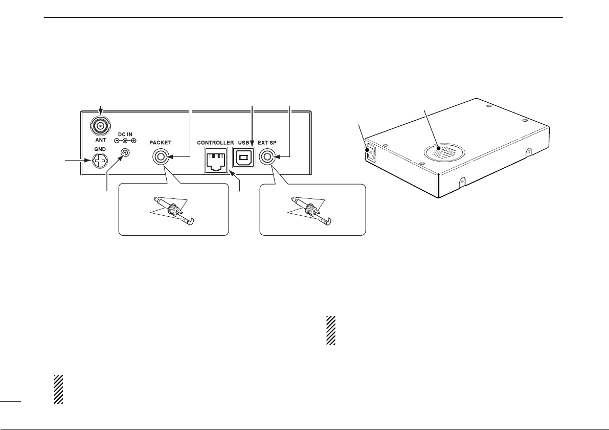
qANTENNA CONNECTOR [ANT]
Connects a 50 Ω antenna with a BNC connector and a 50
Ω coaxial cable.
wPACKET JACK [PACKET]
Connects a TNC (Terminal Node Controller), etc. for data
communications. The receiver can support 9600 bps
packet communication (AFSK).
eUSB CONNECTOR [USB]
Connects to a PC via the supplied USB cable.
• No connection is necessary when the IC-R1500’s controller is in
use.
CAUTION: NEVER insert any other object than a USB
cable, such as a metallic object, otherwise the Main unit
may be damaged.
rEXTERNAL SPEAKER JACK [EXT SP]
Connects an 8 Ω external speaker.
• Audio output power is more than 0.5 W.
tCONTROLLER [CONTROLLER]
Connects to a controller via an extension cable.
• No connection is necessary when the control software is in use.
CAUTION: NEVER insert any other object than the controller cable, such as a metallic object, otherwise the
Main unit may be damaged.
yPOWER JACK [DC IN]
Accepts 12 V DC ±15% via the supplied DC power cable.
uGROUND TERMINAL [GND]
Connect this terminal to a ground.
■ Rear panel—main unit
qwer
u
y
2-conductor 3.5 (d) mm (1⁄8˝)/100 kΩ
PACKET jack connection
AUDIO
GND
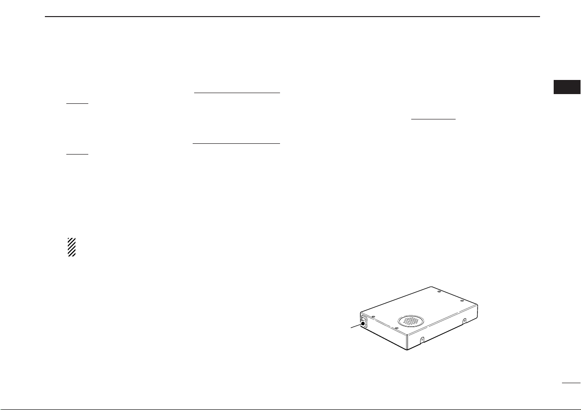
Rear
t
Power switch
EXT SP jack connection
AUDIO
GND
2-conductor 3.5 (d) mm (1⁄8˝)/8 Ω
Speaker
Top
Front
Page 13
8
3
SETTING A FREQUENCY
2
3
■ Turning power ON/OFF
➥ While receiver’s power is OFF, push [PWR] to turn power
ON.
• While receiver power is ON, push and hold [PWR] for 1 sec. to
turn power OFF.
■ Mode selection
D VFO modes
VFO mode is used for the desired frequency setting within the
frequency coverage.
➥ Push [V/MHz•SCAN] to select VFO mode
.
What is VFO?
VFO is an abbreviation of Variable Frequency Oscillator. Frequencies for receiving are generated and controlled by the
VFO.
D Memory mode/Weather channels*
Memory mode is used for operation of memory channels
which have programmed frequencies. Weather channels* are
monitored each 5 sec. when the weather alert function is
turned ON.
*Available for USA/CANADAversions only.
qPush [MR•SKIP] to select memory mode.
•“!” indicator appears when memory mode is selected.
➥ Or push [MR•SKIP] twice and rotate [DIAL] to select the
Weather channel mode, then push [MR•SKIP] again.
• Memory mode, memory banks or Weather channels can be
selected in sequence.
• If weather channel mode is already selected, and you want to
select memory channel mode. Push [MR•SKIP] and rotate
[DIAL] to select “bAnk --,” then push [MR•SKIP] again.
wRotate [DIAL] to select the desired channel.
• Only programmed memory channels can be selected.
• See (p. 16) for memory programming details.
[DIAL]
[MR•SKIP]
[V/MHz•SCAN]
[PWR]
Page 14
9
3
SETTING A FREQUENCY
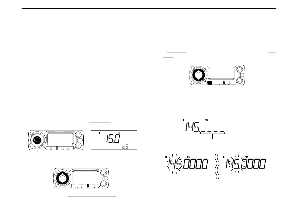
■ Tuning step selection
When using the tuning dial to change the frequency, or when
a scan function is activated, the frequency changes in increments determined by the set tuning step. This can be
changed if desired.
The following tuning step are available.
• 0.01 kHz (10 Hz) • 0.02 kHz (20 Hz) • 0.05 kHz (50 Hz)
• 0.1 kHz (100 Hz) • 0.5 kHz (500 Hz) • 1 kHz
• 2.5 kHz • 5 kHz • 6.25 kHz
• 8.33 kHz • 9 kHz • 10 kHz
• 12.5 kHz • 15 kHz • 20 kHz
• 25 kHz • 30 kHz • 50 kHz
• 100 kHz • 125 kHz • 150 kHz
• 200 kHz • 500 kHz • 1000 kHz (1 MHz)
q Push [V/MHz•SCAN] to select VFO mode, if necessary.
wPush [TS•MODE] to enter tuning step select mode
.
eRotate [DIAL] to select the desired tuning step.
rPush any key to exit tuning step select mode
.
■ Setting a frequency
qRotate [DIAL] to set the frequency.
• If VFO mode is not selected, push [V/MHz•SCAN] to select VFO
mode.
• The frequency changes in the selected tuning steps.
wTo change the frequency band or tune in 1 MHz (10 MHz)
steps, push [V/MHz•SCAN], then rotate [DIAL].
• Pushing and holding [V/MHz•SCAN] for 1 sec. starts scan function. If scan starts, push [V/MHz•SCAN] again to cancel it.
While the band selection mode is selected,
the digits below 100 kHz disappear.
While 10 MHz tuning step is
selected, the 10 MHz digit
blinks.
While 1 MHz tuning step is
selected, the 1 MHz digit
blinks.
[DIAL]
[V/MHz•SCAN]
[DIAL]
[TS•MODE]
Page 15
10
3
SETTING A FREQUENCY
3
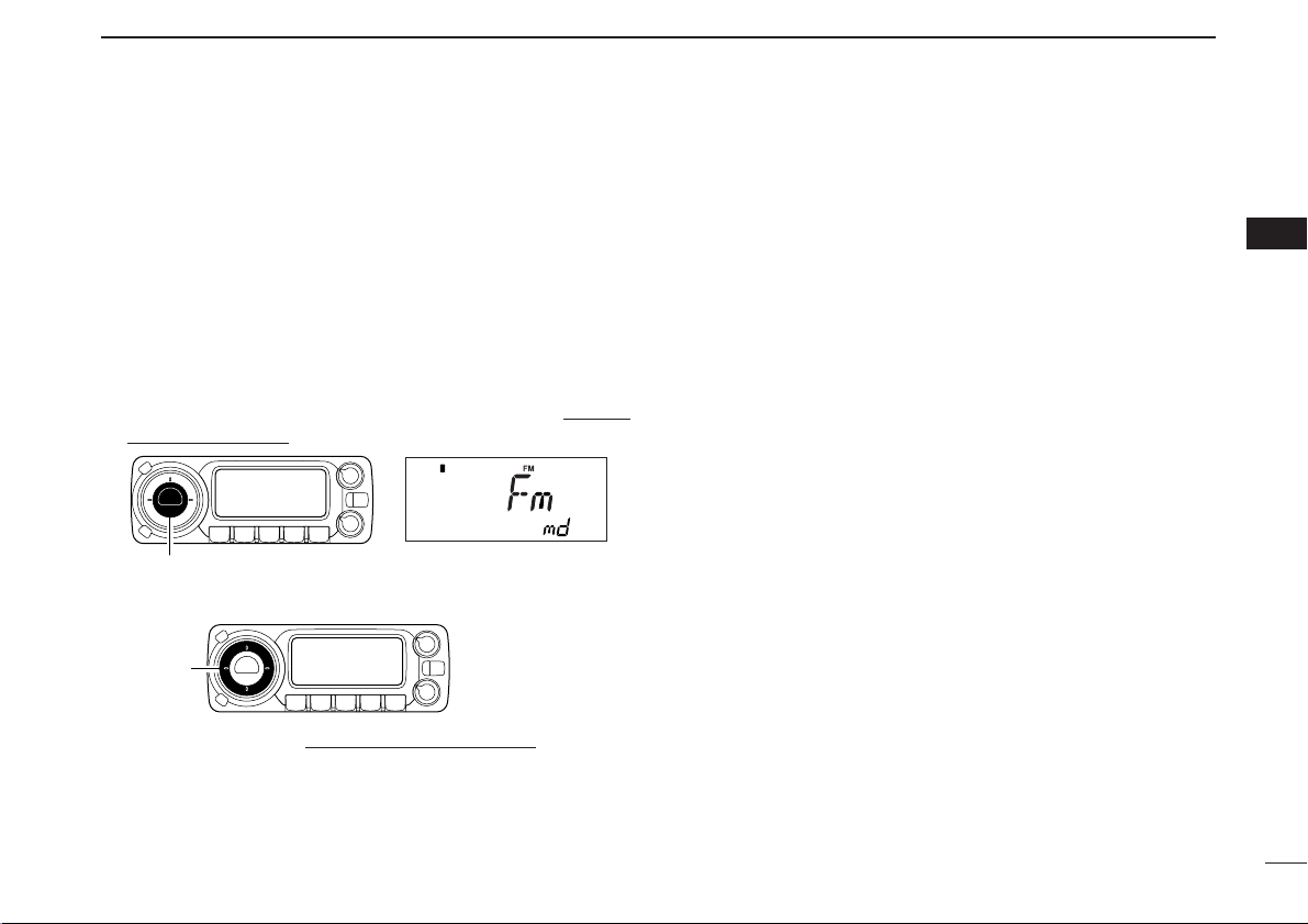
■ Receive mode selection
Receive modes are determined by the physical properties of
the radio signals. The receiver has 6 receive modes: LSB
USB, CW, AM, WFM and FM modes. The mode selection is
stored independently in each memory channels.
Typically, AM mode is used for the AM broadcast stations
(0.495–1.620 MHz) and air band (118–135.995 MHz), and
WFM is used for FM broadcast stations (76–107.9 MHz).
q Push and hold [TS•MODE] for 1 sec. to enter receive
mode select mode.
wRotate [DIAL] to select the desired mode.
ePush any key to exit receive mode select mode
.
[DIAL]
[TS•MODE]
Page 16
11
BASIC OPERATION
4
■ Receiving
qPush and hold [PWR] for 1 sec. to turn power ON.
wSet the audio level.
➥ Push [MONI•T/T-SCAN] to open the squelch.
➥ Rotate [VOL] to adjust the audio level.
➥ Push [MONI•T/T-SCAN] to close the squelch.
eSet the squelch level.
➥ Rotate [SQL] fully counterclockwise in advance, then
rotate [SQL] clockwise until the noise just disappears.
• When interference due to strong signals is received, push
[ATT•PRIO] momentarily to turn the attenuator function.
(p. 12)
rSet the receive frequency and mode. (pgs. 9, 10)
tWhen a signal is received on the set frequency, squelch
opens and the receiver emits audio.
•“BUSY” appears and the S-meter indicator shows the relative
signal strength for the received signal.
■ Monitor function
This function is used to listen to weak signals without disturbing the squelch setting or to open the squelch manually even
when mute functions such as the tone squelch are in use.
➥ Push [MONI•T/T-SCAN] to open the squelch.
• Push [MONI•T/T-SCAN] again to cancel the function.
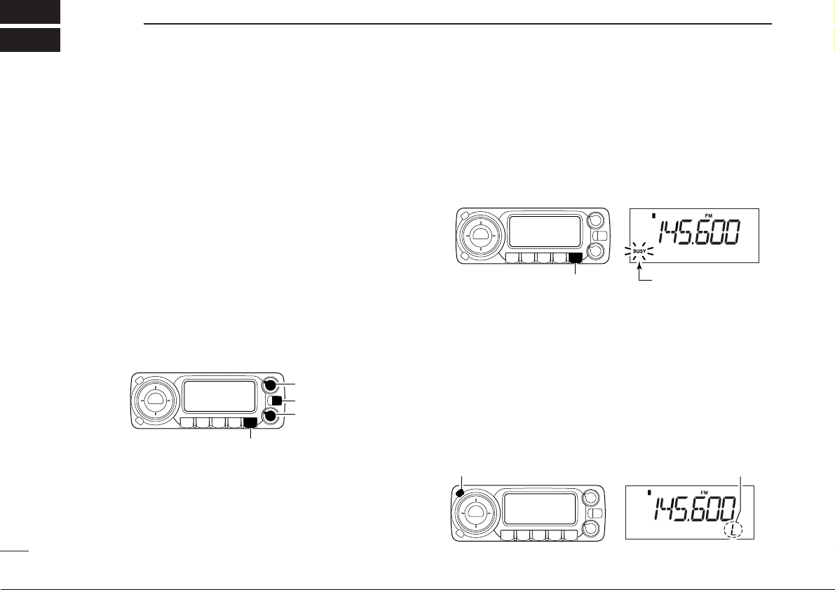
■ Lock function
To prevent accidental frequency changes and unintentional
function access, use the lock function.
➥ Push and hold [SET•LOCK] for 1 sec. to turn the lock func-
tion ON and OFF.
• [SET•LOCK] (lock function only), [MONI•T/T-SCAN] (monitor
function only), [PWR], [VOL] and [SQL] can be used while the
lock function is in use.
[SET•LOCK] Appears
[MONI•T/T-SCAN]
“BUSY” blinks
[PWR]
[VOL]
[SQL]
[MONI•T/T-SCAN]
Page 17
12
4
BASIC OPERATION
4
■ Attenuator function
The attenuator prevents a desired signal from being distorted
when very strong signals are near the desired frequency or
when very strong RF fields, such as from a broadcasting station, are near your location. The attenuator reduces signal
strength by about 20 dB and this function can be activated on
1300 MHz or below.
➥ Push [ATT•PRIO] momentarily to toggle the attenuator
function ON and OFF.
•“ATT” appears when the attenuator function is in use.
■ NB function
The NB (noise blanker) function removes pulse-type noise
when SSB, CW or AM mode is selected.
➥ Push [NB•AGC] to toggle the NB function ON and OFF.
• “NB” appears when the NB function is in use.
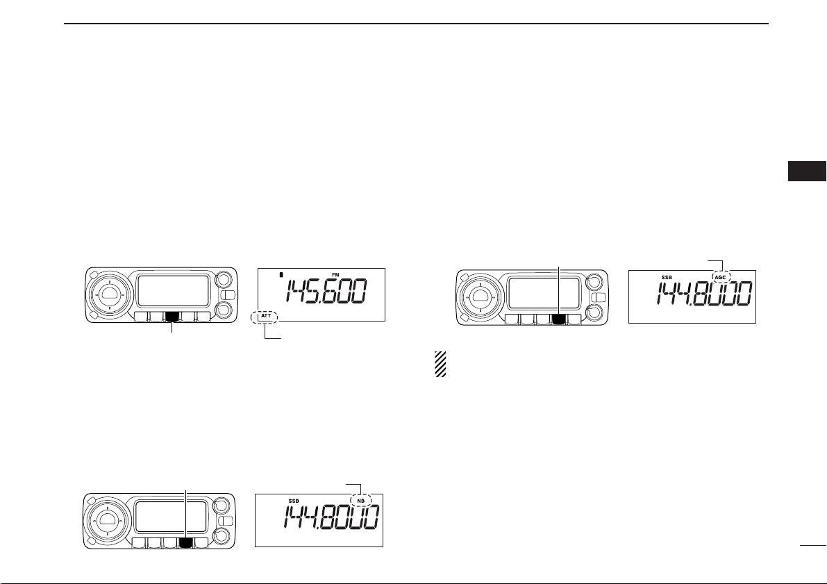
■ AGC function
The AGC (Automatic Gain Control) function controls receiver
gain to produce a constant audio output level even when the
received signal strength varies from fading, etc. A slow-response AGC function is selectable for SSB, CW or AM mode.
➥ Push and hold [NB•AGC] for 1 sec. to toggle the AGC
function Slow and Fast.
•“AGC” appears when the AGC function (FAST) is selected in
SSB, CW or AM mode.
While in FM or WFM mode, the AGC function is fixed as
Fast and AGC Slow cannot be selected.
[ATT•PRIO]
Appears
[NB•AGC]
“NB” appears
[NB•AGC]
“AGC” appears
Page 18

13
4
BASIC OPERATION
■ AFC function [
The AFC (Automatic Frequency Control) function tunes the
displayed frequency automatically when an off-center frequency is received. It activates in FM mode and only when
the selected IF filter is 6 kHz or 15 kHz.
q Select FM mode.
w Push [SET•LOCK] to enter set mode
.
e Push [SET•LOCK] or [S.MW•MW] several times until
“AFC” appears.
r Rotate [DIAL] to toggle the AFC function ON and OFF.
t Push [TS•MODE] or any key below the display to exit set
mode.
• “AFC” appears when the AFC function is in use.
■ VSC function [
The VSC (Voice Squelch Control) function opens the squelch
only when receiving a modulated signal. This function is very
useful while scanning, the VSC pauses only when modulated
signals are received. Scanning continues when unmodulated
or beat signals are received.
q Push [SET•LOCK] to enter set mode
.
w Push [SET•LOCK] or [S.MW•MW] several times until
“VSC” appears.
e Rotate [DIAL] to toggle the VSC function ON and OFF.
r Push [TS•MODE] or any key below the display to exit set
mode.
“VSC” appears
[SET•LOCK]
[DIAL]
[S.MW•MW]
[SET•LOCK]
[DIAL]
[S.MW•MW]
Appears
Page 19

14
4
BASIC OPERATION
4
■ IF filter selection [
The receiver has 2 to 4 IF passband filter widths for each
mode. Selectable passband widths are 3, 6, 15, 50 and 230
(depending on the selected mode).
• Selectable passband width for each mode.
SSB mode : 3 (2.8 kHz) or 6 kHz
CW mode : 3 (2.8 kHz) or 6 kHz
AM mode : 3 (2.8 kHz), 6 kHz, 15 kHz or 50 kHz
WFM mode: 50 kHz or 230 kHz
FM mode : 6 kHz, 15 kHz or 50 kHz
q Push [SET•LOCK] to enter set mode
.
w Push [SET•LOCK] or [S.MW•MW] several times until “FIL”
appears.
e Rotate [DIAL] to select the desired IF passband width.
r Push [TS•MODE] or any key below the display to exit set
mode.
■ IF shift function [
The IF shift function electronically changes the passband frequency of the IF (Intermediate frequency) cuttting out higher
or lower frequency components of the IF to reject interference. This function is available when the receive mode is
SSB or CW mode, and shifts the IF frequency up to ±25 steps
(in 1 step: 50 Hz).
q Push [SET•LOCK] to enter set mode
.
w Push [SET•LOCK] or [S.MW•MW] several times until
“SFt” appears.
e Rotate [DIAL] to set the shifting direction and frequency
range.
r Push [TS•MODE] or any key below the display to exit set
mode.
[SET•LOCK]
[DIAL]
[S.MW•MW]
[SET•LOCK]
[DIAL]
[S.MW•MW]
Center position
(default)
HighestLowest
Page 20

15
4
BASIC OPERATION
Duplex communication uses two different frequencies for transmitting and receiving. Generally, duplex is used in communication through a repeater, some utility communications, etc.
During duplex operation, the transmit station frequency is
shifted from the receive station frequency by the offset frequency. Repeater information (offset frequency and shift direction) can be programmed into memory channels. (p. 16)
DD
Setting [
qPush [SET•LOCK] to enter set mode.
wPush [SET•LOCK] or [S.MW•MW] several times until the
duplex direction setting item “OFF
dP,” “DUP– dP” or “DUP+
dP” appears.
eRotate [DIAL] to select the duplex direction, “DUP–
dP” or
“DUP+
dP.”
rPush [SET•LOCK] once to advance to the offset frequency
setting item.
tRotate [DIAL] to set the desired offset frequency within
0.000–1000.000 MHz range.
• The tuning step, selected in VFO mode, is used for setting.
• Push [V/MHz• SCAN] then rotate [DIAL] to change the fre-
quency in 10 MHz steps, or push again then rotate [DIAL] to
change the frequency in 1 MHz steps. (Each push toggles
1MHz, 10 MHz or selected tuning steps.)
yPush [TS•MODE] or any key below the display to exit set
mode.
DD
Operation
qSet the receive station frequency (repeater output frequency).
wPush [MONI•T/T-SCAN] to monitor the transmit station fre-
quency
(repeater input frequency) directly.
[MONI•T/T-SCAN]
Frequency shifts
the offset frequency
■ Duplex operation
[SET•LOCK]
[DIAL]
[S.MW•MW]
Page 21

16
5
MEMORY OPERATION
4
5
■ General description
The receiver has 1100 memory channels including 100 scan
edge memory channels (50 pairs) for storage of often-used
frequencies. And a total of 21 memory banks, A to H, J to R,
T, U, W and Y are available for storing groups of frequencies,
etc. Up to 100 channels can be assigned to a bank.
DD
Memory channel contents
The following information can be programmed into memory
channels:
• Operating frequency (p. 9)
• Receive mode (p. 10)
• Duplex direction (DUP+ or DUP–) with an offset frequency (p. 15)
•Tone squelch or DTCS squelch ON/OFF (p. 33)
•Tone squelch frequency or DTCS code with polarity
(p. 38)
• Scan skip information (p. 28)
■ Memory channel selection
q Push [MR•SKIP] to select memory mode.
•“!” indicator appears.
w Rotate [DIAL] to select the desired memory channel.
• Programmed memory channels can only be selected.
[MR•SKIP] “!” appears
If memory banks or weather channels* mode appears at
step q, push [MR•SKIP] and rotate [DIAL] to select “bAnk
--,” then push [MR• SKIP] again to return to channel selection.
*Available for USA/CANADA versions only.
Page 22

17
5
MEMORY OPERATION
VFO settings, including the set mode contents such as subaudible tone frequency, offset and scan skip information can
be programmed into a memory channel.
qPush [V/MHz•SCAN] to select VFO mode
.
wSet the desired frequency using [DIAL].
➥ Set other data (e.g. subaudible tone frequency, scan
skip information, etc.) if required.
ePush [S.MW•MW] to enter select memory write mode
.
•“!” indicator and the memory channel number blink.
rRotate [DIAL] to select the desired memory channel to be
programmed.
• Memory channels not yet programmed are blank.
tPush and hold [S.MW•MW] for 1 sec. to program.
•3 beeps sound
• Memory channel number automatically increases when continuing to push [S.MW•MW] after programming.
✔CONVENIENT
Memory programming can be made quicker by copying memory information to different memory channels (p.19).
■ Programming a memory channel
[EXAMPLE]: Programming 145.800 MHz into memory channel 20 (blank channel).
Push
Rotate for setting frequency, etc.
Push .
“
Rotate
Push for 1 sec. and continue to push
“
“
Beep
“
Beep
Beep
“
“
Beep
“
Beep
➠
Page 23

18
5
MEMORY OPERATION
5
■ Programming channel names
Each memory channel can be programmed with an alphanumeric channel name for easy recognition and can be indicated independently by channel. Names can be a maximum
of 6 characters— see the table below for available characters.
qSelect the desired memory channel to be programmed.
➥ Push [MR•SKIP] to select memory mode
, then rotate
[DIAL] to select the desired memory channel.
wPush [S.MW•MW] to enter select memory write mode
.
•“!” indicator and the memory channel number blink.
e Push [TS•MODE] twice to select the memory name pro-
gramming condition, “m nAmE.”
• Frequency readouts disappear and a cursor blinks.
r Rotate [DIAL] to select the desired character.
• The selected character blinks.
t Push [SET•LOCK] to move the cursor to the right.
• Repeat pushing [SET•LOCK] to return to the first digit.
y Repeat steps r and t until the desired channel name is
displayed.
u Push and hold [S.MW•MW] for 1 sec. to program the
name and exit select memory write mode
.
[EXAMPLE]: Programming “CLUB” into memory channel 12.
(
H
(
(Z)
(8)
)
Q
)
(space)
(I)
(
R
)
(0)
(9)
(A)
(J)
(S)
(1)
(+)
(B)
(K)
(T)
(2)
(–)
(C)
(L)
(U)
(3)
D
)
(
(M)
(V)
(4)
(/)
(=)
(E)
(N)
(W)
(5)
(F)
(O)
(X)
(6)
(G)
(P)
(Y)
(7)
Select
memory channel.
Rotate
Push Push twice
Push
previous
steps.
Push for 1 sec.Repeat the
“
“
Beep
Beep
“
Beep
“
“
Page 24

19
5
MEMORY OPERATION
DD
To indicate the channel name [
The channel name indication can be set independently for
eace memory channel.
qSelect the desired memory channel.
➥ Push [MR•SKIP] to select memory mode
, then rotate
[DIAL] to select the desired memory channel.
•“!” and memory channel number appear.
wPush [SET•LOCK] to enter set mode.
ePush [SET•LOCK] or [S.MW•MW] several times to select
“Anm” item.
rRotate [DIAL] to turn the memory name indication ON.
tPush [TS•MODE] to exit set mode
.
NOTE: When no memory name is programmed, the stored
frequency is displayed.
■ Copying memory contents
This function transfers a memory channel’s contents to VFO
(or another memory channel). This is useful when searching
for signals near a memory channel frequency and for recalling
the subaudible tone frequency, etc.
D Memory➪VFO
qSelect the desired memory channel to be transferred.
➥ Push [MR•SKIP] to select memory mode
, then rotate
[DIAL] to select the desired memory channel.
•“!” and memory channel number appear.
wPush and hold [S.MW•MW] for 3 sec. to transfer the se-
lected memory channel contents to VFO mode
.
• VFO mode is selected automatically.
D Memory➪memory
qSelect the desired memory channel to be transferred.
➥ Push [MR•SKIP] to select memory mode
, then rotate
[DIAL] to select the desired memory channel.
•“!” and memory channel number appear.
w Push [S.MW•MW] momentarily.
•“!” and memory channel number blink.
e Rotate [DIAL] to select the target memory channel.
• Scan edge channels, 0A/0B to 49A/49B can also be selected.
r Push and hold [S.MW•MW] for 1 sec. to transfer the se-
lected memory channel contents to the target memory
channel.
• The targeted memory channel and transferred contents are displayed.
Page 25

20
5
MEMORY OPERATION
5
[EXAMPLE]: Transferring the contents of memory channel 30 to VFO.
[EXAMPLE]: Transferring the contents of memory channel 22 to channel 23.
Push to select memory mode.
Rotate for selecting memory channel.
Push to select memory mode.
Rotate for selecting memory channel.
Select the target channel.
Push for 3 sec.
Push .
Push for 1 sec.
Page 26

21
5
MEMORY OPERATION
■ Memory clearing
Contents of programmed memories can be cleared (erased),
if desired.
qPush [V/MHz•SCAN] to select VFO mode
.
wPush [S.MW•MW] to enter select memory write mode
.
•“!” and the memory channel number blink.
eRotate [DIAL] to select the memory channel to be cleared.
rPush [TS•MODE] three times to select “CLEAR,” then
push and hold [S.MW•MW] for 1 sec.
•3 beeps sound.
• The cleared channel display changes to blank
•“!” and the memory channel number blink continuously.
tPush [V/MHz•SCAN] to return to VFO mode.
☞NOTE: Be careful!— the contents of cleared memories
CANNOT be recalled.
[EXAMPLE]: Clearing memory channel 20.
Push to select VFO.
Push three times, then push for 1 sec.
Push .
Rotate for selecting memory channel.
Push to return to VFO.
“
“
Beep
“
Beep
Beep
“
“
Page 27

22
5
MEMORY OPERATION
5
The IC-R1500 has a total of 21 banks (A to H, J to R, T, U,
W, Y). Regular memory channels, 0 to 999, may assigned
into the desired bank for easy memory management.
qSelect the desired memory channel.
➥ Push [MR•SKIP] to select memory mode
, then rotate
[DIAL] to select the desired memory channel.
•“!” and memory channel number appear.
wPush [S.MW•MW] to enter select memory write mode.
•“!” indicator and the memory channel number blink.
e Push [TS•MODE] once to select “bAnk.”
r
Rotate [DIAL] to select the desired bank and bank channel.
• Push [SET•LOCK] to toggle the bank or bank channel selection.
• Banks A to H, J to R, T, U, W and Y are available.
• Only vacant bank channel numbers will be displayed.
tPush and hold [S.MW•MW] for 1 sec. to program the bank
and exit select memory write mode
.
Bank selection Bank channel selection
[TS•MODE]
After [TS•MODE]
released
■ Memory bank setting
[
Page 28

23
5
MEMORY OPERATION
■ Memory bank selection
qPush [MR•SKIP] to select memory mode.
wPush [MR•SKIP] again to enter memory type selection
mode.
eRotate [DIAL] to select the desired bank (A to H, J to R, T,
U, W or Y).
• Only programmed banks are displayed.
rPush any key to set the bank indication.
• Bank’s indicator appears at top of the memory channel.
tRotate [DIAL] to select the contents in the bank.
yTo return to regular memory mode
, repeat steps w–r and
select “bAnk --” at step e.
• Memory bank indication
■ Transferring bank contents
[
The bank contents of programmed memory channels can be
cleared or transferred to another bank.
INFORMATION: Even if the bank is cleared of memory
channels, the memory channel contents still remain programmed.
qSelect the desired bank contents to be transferred or
erased from the bank.
➥ Push [MR•SKIP] to select memory mode
.
➥ Push [MR•SKIP] again then rotate [DIAL] to select the
desired memory bank.
➥ Push any key to select the bank then rotate [DIAL] to
select the desired contents.
wPush [S.MW•MW] to enter select memory write mode
.
•“!” indicator and the memory channel number blink.
[MR•SKIP][DIAL] Bank’s indicator appears
[MR•SKIP][DIAL]
Bank indicator appears
Page 29

24
5
MEMORY OPERATION
5
ePush [TS•MODE] once to select “bAnk.”
• The bank’s indicator and bank channel are displayed.
rRotate [DIAL] to select the desired bank indicator to trans-
fer or erase.
• Push [SET•LOCK] to toggle the bank or bank channel selection.
• Select “-- --” indication when erasing the contents from the bank.
•Vacant bank channel numbers are only be displayed.
tPush and hold [S.MW•MW] for 1 sec. to program the bank
and exit select memory write mode
.
yRepeat steps q to t for transferring or erasing an another
bank’s contents.
[S.MW•MW]
Bank selection Bank channel selection
[TS•MODE]
After [TS•MODE]
released
Page 30

25
SCAN OPERATION
6
■ Scan types
Scanning searches for signals automatically and makes it
easier to locate new stations.
There are 5 scan types and 4 resume conditions to suit your
operating needs.
FULL SCAN (p. 26)
Repeatedly scans all frequencies over the entire band.
Some frequency ranges are
not scanned according to the
frequency coverage of the receiver’s version.
10
kHz
3299.9999
MHz
Scan
Jump
ALL/SELECTED BANK
SCAN (p. 26)
Repeatedly scans all bank
channels or selected bank
channels. Skip scan is also
available.
SKIP
SKIP
A99
A03
A00 A01 A02
A04
A98
A05
PROGRAMMED SCAN
(p. 26)
Repeatedly scans between
two user-programmed frequencies. Used for checking
for frequencies within a specified range such as repeater
output frequencies, etc.
Band
edge
xxA xxB
Band
edge
Scan edges
Scan
Jump
MEMORY (SKIP) SCAN
(p. 26)
Repeatedly scans memory
channels except those set as
skip channel. Skip channels
can be turned ON and OFF
by pushing and holding
[MR•SKIP] in memory mode.
SKIP
SKIP
M 0
M 4
M 1 M 2 M 3
M 5
M 199
M 6
FREQUENCY/MEMORY
SKIP FUNCTION (p. 28)
Skips unwanted frequencies
or channels that inconveniently stop scanning. This
function can be turned ON
and OFF by pushing and
holding [MR•SKIP] in memory
mode.
Band
edge
Band
edge
Scan
SKIP SKIP
Jump
Page 31

26
6
SCAN OPERATION
6
■ Scan start/stop
D Preparation
Scan resume condition (p. 29); program scan edges (p. 27);
program two or more memory channels (p. 17); set skip settings (p. 28), if desired.
D Operation
qPush [V/MHz•SCAN] to select VFO mode for full/pro-
grammed scan; or push [MR•SKIP] to select memory
mode for memory/bank scan.
• Select the desired bank in memory type selection mode for bank
scan.
wSet the squelch level to the point where noise is just muted.
ePush and hold [V/MHz•SCAN] for 1 sec. to start the scan.
•To change the scanning direction, rotate [DIAL].
• The memory channel readout blinks the scan type as below.
r Push [TS•MODE] (or [SET•LOCK]) to select full and pro-
grammed scan (P00 to P49), if VFO is selected in step q.
t To stop the scan, push [V/MHz•SCAN].
About the scanning steps: The selected tuning step in
each frequency band (in VFO mode
) is used during scan.
The bank-link setting can be changed in set mode
. See
(p. 41) for details.
IMPORTANT!: To perform memory or bank scan, two or
more memory/bank channels MUST be programmed, otherwise the scan will not start.
• During full scan • During programmed scan • During memory scan • During bank scan
Push [SET•LOCK] to select full (ALL) or programmed scan (P00–P49) in
sequence.
While pushing and holding [V/MHz•SCAN], rotate [DIAL]
also to select full (ALL) or programmed scan (P00–P49).
Indicates scan edge channels.
• P01 stands for 01A/01B
• P00 to P49 are available when
they are programmed, and selected with [SET•LOCK].
Indicates bank channel.
NOTE: When SSB, CW, AM, FM or WFM mode frequencies
are programmed into memory channels randomly, memory
scan is slow because changing modes takes time. In this
case, assign the SSB, CW, AM, FM or WFM mode
frequencies into separate banks where bank scan can be
used. And using the bank scan is helpful.
Page 32

27
6
SCAN OPERATION
■ Scan edges programming
Scan edges can be programmed in the same manner as
memory channels. Scan edges are programmed into scan
edges, 0A/0B to 49A/49B, in memory channels.
q Push [V/MHz•SCAN] to select VFO mode
.
w Set the edge frequency of the desired frequency range:
➥ Set the frequency using [DIAL].
➥ Set other data
(e.g. tone squelch, etc.), if desired.
e Push [S.MW•MW].
•“!” indicator and channel number blink.
r Rotate [DIAL] to select one of scan edge channel, 0A to
49A.
t Push and hold [S.MW•MW] for 1 sec. to program.
•3 beeps sound and VFO mode is automatically selected.
• Scan edge 0B to 49B is automatically selected when continuing
to push [S.MW•MW] after programming.
y To program a frequency for the other pair of scan edges,
0B to 49B, repeat steps q to r.
• If the same frequency is programmed into a pair of scan edges,
programmed scan will not function.
[EXAMPLE]: Programming 144.000 MHz into scan edge 1A.
Push
Rotate
Rotate for setting frequency, etc.
Push for 1 sec. and continue to push
“
“
Beep
“
Beep
Beep
“
“
Push .
“
Beep
➠
“
Beep
Page 33

28
6
SCAN OPERATION
6
■ Skip scan
D Skip channel/frequency setting
You can set the selected memory channel as a skip channel
which is skipped during memory skip scan. In addition, it can
be set as a skip channel for both memory skip scan and frequency skip scan. These are useful to speed up the scan interval.
qSelect a memory channel.
➥ Push [MR•SKIP] to select memory mode
, then rotate
[DIAL] to select the desired memory channel to be a
skip channel.
•“!” and memory channel number appear.
wPush and hold [MR•SKIP] for 1 sec. several times to set
the skip condition.
• (no indication): The channel is scanned during scan.
• ~ : The channel is skipped during scan.
• P~ : The channel is skipped during scan and the programmed frequency is skipped during VFO scan,
such as programmed scan.
D Skip scan setting [
q Push [SET•LOCK] to enter set mode.
w Push [SET•LOCK] or [S.MW•MW] several times until
“PSC” appears.
e Rotate [DIAL] to toggle the skip scan function ON and
OFF.
r Push [TS•MODE] or any key below the display to exit set
mode.
t Then start the scan to activate the skip scan (memory skip
scan or frequency skip scan).
[MR•SKIP]
The display shows that
memory channel 16 is
set as a skip channel.
[SET•LOCK]
[DIAL]
[S.MW•MW]
[TS•MODE]
Page 34

29
6
SCAN OPERATION
The scan resume condition can be selected a timed or pause
scan. The selected resume condition is also used for priority
watch. (p. 30)
q Push [SET•LOCK] to enter set mode
.
w Push [SET•LOCK] or [S.MW•MW] several times until
“SCt” or “SCP” appears.
e Rotate [DIAL] to set the desired timer:
• “SCP-2” : Scan pauses until the signal disappears and then resumes 2 sec. later.
• “SCt-15” : Scan pauses 15 sec. while receiving a signal.
• “SCt-10” : Scan pauses 10 sec. while receiving a signal.
• “SCt-5” :Scan pauses 5 sec. while receiving a signal.
r Push [TS•MODE] to exit set mode.
■ Scan resume condition [
The display shows that the
scan will resume 15 sec. after
it stops.
[SET•LOCK]
[SET•LOCK]
[DIAL]
[S.MW•MW]
Page 35

30
7
PRIORITY WATCH
6
7
■ Priority watch types
Priority watch checks for signals on the frequency every
5 sec. while operating on a VFO frequency or scanning. The
receiver has 2 priority watch types to suit your needs.
The watch resumes according to the selected scan resume
condition. See (p. 29) for details.
NOTE: If the pocket beep function is activated, the receiver
automatically selects the tone/DTCS squelch function
when priority watch starts.
■ Priority watch operation
q Select VFO mode; then, set an operating frequency.
w Set the watched channel(s).
For memory channel watch:
Select the desired memory channel.
For memory scan watch:
Select memory mode
, or the desired bank group; then,
push and hold [V/MHz•SCAN] for 1 sec. to start memory
scan.
e Push and hold [ATT•PRIO] for 1 sec. to start the watch.
• The receiver checks the memory/bank channel(s) every 5 sec.
• The watch resumes according to the selected scan resume con-
dition. (p. 29)
• While the watch is paused, pushing and holding [ATT•PRIO] for
1 sec. resumes the watch manually.
r Push and hold [ATT•PRIO] for 1 sec. to stop the watch.
MEMORY CHANNEL WATCH
While operating on a VFO frequency, priority watch checks for
a signal on the selected memory
channel every 5 sec.
•Amemory channel with skip information can be watched.
5 sec.
VFO
frequency
Memory
channel
MEMORY SCAN WATCH
While operating on a VFO frequency, priority watch checks for
signals on each memory channel in sequence.
• The memory skip function and/or
memory bank scan is useful to
speed up the scan.
5 sec.
VFO
frequency
SKIP
Mch 000
Mch 001
Mch 001
Mch 999
[ATT•PRIO]
“PRIO” appears
Page 36

31
POCKET BEEP AND TONE SQUELCH
8
■ Pocket beep operation
This function uses subaudible tones for calling and can be
used as a “common pager” to inform you that someone has
called while you were away from the receiver.
D Waiting for a call from a specific station
q Set the operating frequency in FM mode.
w Push [SET•LOCK] to enter set mode
.
e Push [SET•LOCK] or [S.MW•MW] several times until “Ct”
(when selecting the tone squelch frequency) or “dt” (when
selecting the DTCS code squelch) appears.
r Rotate [DIAL] to select the desired tone frequency or
DTCS code.
t When operating the pocket beep function with DTCS code
squelch, push [SET•LOCK] once then rotate [DIAL] to select the DTCS polarity.
y Push [TS•MODE] or any key below the display to exit set
mode.
u Push and hold [MONI•T/T-SCAN] for 1 sec to enter tone
squelch selection mode, then rotate [DIAL] until “S ”
or “ S” appears to turn the pocket beep function ON
with tone squelch or DTCS squelch, respectively.
[SET•LOCK]
DTCS polarity setting
Tone squelch frequency setting DTCS code setting
[DIAL]
Appears when the pocket beep
with tone squelch is turend ON.
[MONI•T/T-SCAN][DIAL]
Appears when the pocket beep
with DTCS squelch is turned ON.
Page 37

32
8
POCKET BEEPAND TONE SQUELCH
8
i Push any key to exit tone squelch selection mode.
o When a signal with a matching tone is received, the re-
ceiver emits beep tones and blinks “S.”
• Beep tones sound for 30 sec. and “S” blinks. To stop the
beeps and blinking manually, push any key.
!0 Push and hold [MONI•T/T-SCAN] for 1 sec. to enter tone
squelch selection mode, then rotate [DIAL] to cancel the
tone squelch or DTCS squelch function.
• “oFF” is selected for turning the function OFF.
D Available tone frequency list
NOTE: The receiver has 51 tone frequencies and conse-
quently their spacing is narrow compared to units having
38 tones. Therefore, some tone frequencies may receive
interference from adjacent tone frequencies.
D Available DTCS code list
D Calling a waiting station using pocket beep
Asubaudible tone matched with the station’s CTCSS tone frequency or 3-digit DTCS code with the correct polarity is necessary. Use the tone squelch on the next page (p. 33).
023
025
026
031
032
036
043
047
051
053
125
131
132
134
143
145
152
155
156
162
245
246
251
252
255
261
263
265
266
271
356
364
365
371
411
412
413
423
431
432
506
516
523
526
532
546
565
606
612
624
054
065
071
072
073
074
114
115
116
122
165
172
174
205
212
223
225
226
243
244
274
306
311
315
325
331
332
343
346
351
445
446
452
454
455
462
464
465
466
503
627
631
632
654
662
664
703
712
723
731
732
734
743
754
67.0
69.3
71.0
71.9
74.4
77.0
79.7
82.5
85.4
88.5
91.5
94.8
097.4
100.0
103.5
107.2
110.9
114.8
118.8
123.0
127.3
131.8
136.5
141.3
146.2
151.4
156.7
159.8
162.2
165.5
167.9
171.3
173.8
177.3
179.9
183.5
186.2
189.9
192.8
196.6
199.5
203.5
206.5
210.7
218.1
225.7
229.1
233.6
241.8
250.3
254.1
Appears when the pocket beep
with tone squelch is activated.
Appears when the pocket beep
with DTCS squelch is activated.
Page 38

33
8
POCKET BEEPAND TONE SQUELCH
■ Tone/DTCS squelch operation
The tone or DTCS squelch opens only when receiving a signal with the same pre-programmed subaudible tone or DTCS
code. You can silently wait for a signal using the same tone.
q Set the operating frequency in FM mode.
w Program the CTCSS tone frequency or DTCS code in set
mode. (p. 31)
e Push and hold [MONI•T/T-SCAN] for 1 sec. to enter
tone squelch selection mode
, then rotate [DIAL] until “ ”
or “ ” appears in the function display.
r When a signal with a matching tone is received, the
squelch opens and the receiver emits audio.
• When the received signal includes an unmatched tone, the
squelch does not open. However, the S-meter indicator shows
the received signal strength.
•To open the squelch manually, push [MONI•T/T-SCAN].
t To cancel the tone squelch or DTCS squelch function, re-
peat steps e until “oFF” appears, then push any key.
D Reverse action for tone or DTCS squelch
➥ Enter tone squelch selection mode as described in steps
q to e as shown left, then rotate [DIAL] to select either
reverse action for the tone or DTCS squelch as below.
How does the Reverse action work?
When the reverse action is selected for either the tone
squelch, “tSqL-r,” or DTCS squelch, “dtCS-r,” and a signal
with the matched tone (or DTCS) is received, the squelch
closes, and the receiver mutes the signal. You can listen to
signals with any tone other than the specified one.
Tone OFF setting
for DTCSfor Tone squelch
DTCS settingTone squelch setting
Page 39

34
8
POCKET BEEPAND TONE SQUELCH
8
■ Tone scan
By monitoring a signal using with pocket beep, tone or DTCS
squelch, you can determine the tone frequency or DTCS
code necessary to open the squelch.
q Set the desired operating frequency or memory channel to
be checked for a tone frequency or code.
w Push and hold [MONI•T/T-SCAN] for 1 sec and rotate
[DIAL] to select the tone type, tone squelch or DTCS, to
be scanned.
•Either “ ” or “ ” appears.
e Push and hold [MONI•T/T-SCAN] for 1 sec. to start the
tone scan.
•To change the scanning direction, rotate [DIAL].
r When the CTCSS tone frequency or 3-digit DTCS code is
matched, the squelch opens and the tone frequency is
temporarily programmed into the VFO or memory channel.
• The tone scan pauses when a CTCSS tone frequency or 3-digit
DTCS code is detected.
• The decoded CTCSS tone frequency or 3-digit DTCS code is
used for the tone decoder depending on the selected tone condition or type in step w.
-“ ”: CTCSS tone decoder
-“ ”: DTCS tone decoder
t Push any key to stop the scan.
NOTE: The decoded tone frequency is programmed temporarily when a memory is selected. However, this will be
replaced by the programmed information when the memory channel is re-selected.
[MONI•T/T-SCAN]
During CTCSS frequency scan During DTCS code scan
Page 40

†
Appears when accessing set mode from VFO mode only.
‡
Appears when accessing set mode from memory mode only.
When the UT-106 is installed
• Key-touch beep • Display dimmer• Auto power OFF• Beep output level
• Display color
• NR function
*
4
• ANF function*
4
• Squelch delay
• IF shift
*
3
: Push
: Push
SSB/CW mode only
*
1
Available for USA/CANADA versions only.
*
2
Appears while in FM mode only.
*
3
Appears while in SSB/CW mode only.
*
4
Appears when the UT-106 is selected.
*
5
Appears except WFM mode.
35
SET MODE
9
■ General
DD
Set mode operation
q Push [SET•LOCK] to enter set mode.
w Push [SET•LOCK] or [S.MW•MW] to select the desired
item.
e Rotate [DIAL] to select the desired condition of the item.
r Push [TS•MODE] or any key below the display to exit set
mode.
■ Set mode items
Page 41

• Weather alert*
1
• TSQL frequency • DTCS code • DTCS polarity• Offset frequency
• Duplex direction
• Display contrast
• Scan resume timer • VSC function
*
5
• AFC function*
2
• IF filter
• Program skip
†
• Scan skip area
†
• Bank link function
‡
• Memory name
‡
FM mode only
USA/CANADA versions only
Bank link-On
Memory mode only
VFO mode only
Except WFM mode
36
9
SET MODE
1
2
3
4
5
6
7
8
9
10
11
12
13
14
15
16
Page 42

37
9
SET MODE
DD
Key-touch beep
The key-touch beep can be turned OFF for silent operation.
(default: ON)
Even when this item is set to OFF, the power-on beep and
pocket beep function still sound. The power-on beep can
not be set to OFF.
DD
Beep output level
Adust the beep level from 1 to 9 for key-touch beep, power-on
beep and pocket beep function. (default: 5)
When the previous set mode item “bEP” is set to OFF, this
setting level does not affect key-touch.
DD
Auto power OFF
The receiver can be set to automatically turn OFF with a beep
after a specified period during which no key operations are
performed.
30 min., 1 hour, 2 hours and OFF can be specified. The specified period is retained even when the receiver is turned OFF
by the auto power OFF function. To cancel the function, select
“OF” for this item in set mode
. (default: OFF)
DD
Display dimmer
Adjust the display lighting level.
The levels 1 (dark) to 8 (bright: default) are available.
Page 43

38
9
SET MODE
9
DD
Display color
The display color can be set to amber (default), yellow or
green.
DD
Display contrast
The LCD contrast can be adjusted through 9 levels.
(default: 5)
DD
Duplex direction
Sets the duplex direction. The displayed frequency shifts by
the programmed offset frequency (see next item) when monitor function is in use (pushing [MONI•T/T-SCAN]).
• OFF : Simplex operation. (default)
• DUP–: The displayed frequency shifts down during mon-
itor.
• DUP+: The displayed frequency shifts up during monitor.
DD
Offset frequency
Sets the duplex offset frequency for each frequency band independently within a 0 to 1000 MHz range. During duplex operation (DUP– or DUP+), the monitoring frequency (pushing
[MONI•T/T-SCAN]) shifts by the offset frequency.
The default value may differ according to the selected frequency band
(before accessing set mode) and receiver version.
The selected tuning step in VFO mode
is used for setting
the offset frequency.
Yellow setting Green setting
Page 44

39
9
SET MODE
DD
Tone frequency
Sets subaudible tone frequency for tone squelch operation.
Total of 51 tone frequencies (67.0–254.1 Hz) are available.
(default: 88.5 Hz)
•Available tone frequency list
DD
DTCS code
Sets DTCS code for DTCS squelch operation. Total of 104
codes (023–754) are available. (default: 023)
•Available DTCS code list
DD
DTCS polarity
Selects DTCS polarities from n (normal) and r (reverse).
(default: n)
normal (default) reverse
023
025
026
031
032
036
043
047
051
053
125
131
132
134
143
145
152
155
156
162
245
246
251
252
255
261
263
265
266
271
356
364
365
371
411
412
413
423
431
432
506
516
523
526
532
546
565
606
612
624
054
065
071
072
073
074
114
115
116
122
165
172
174
205
212
223
225
226
243
244
274
306
311
315
325
331
332
343
346
351
445
446
452
454
455
462
464
465
466
503
627
631
632
654
662
664
703
712
723
731
732
734
743
754
67.0
69.3
71.0
71.9
74.4
77.0
79.7
82.5
85.4
88.5
91.5
94.8
097.4
100.0
103.5
107.2
110.9
114.8
118.8
123.0
127.3
131.8
136.5
141.3
146.2
151.4
156.7
159.8
162.2
165.5
167.9
171.3
173.8
177.3
179.9
183.5
186.2
189.9
192.8
196.6
199.5
203.5
206.5
210.7
218.1
225.7
229.1
233.6
241.8
250.3
254.1
Page 45

40
9
SET MODE
9
DD
VSC setting
Turns VSC (Voice Squelch Control) ON and OFF.
(default: OFF)
DD
Scan resume timer
Selects scan resume timer from SCT-15 (default), SCT-10,
SCT-5 and SCP-2. Scan resumes after the specified period
when the received signal disappears.
• SCT-15/10/5 : Scan pauses for 15/10/5 sec. when the
received signal disappears.
• SCP-2 : Scan pauses on a signal until signal disappears, then resumes 2 sec. after the
signal disappears.
DD
Program scan skip setting
Sets the program scan skip setting ON and OFF for VFO
scan operation, such as programmed scan.
(default: ON)
This item appears when set mode
is accessed from VFO
mode only.
DD
Scan skip area setting
Sets the pre-programmed scan skip area setting ON and OFF
for VFO scan operation, such as programmed scan.
This item appears only when the scan skip area setting is programmed by the cloning (p. 44) and set mode
is accessed
from VFO mode
.
Page 46

41
9
SET MODE
DD
Memory name setting
Sets memory name appearance ON (appear) and OFF (does
not appear; default).
This item appears when set mode
is accessed from memory
mode only.
DD
Memory bank link function
Sets the memory bank link function ON and OFF (default).
The link function provides continuous banks scan, that scans
all contents in the selected banks during bank scan.
This item appears when set mode
is accessed from memory
mode only.
• Bank link setting
q Rotate [DIAL] to select the memory bank link function ON.
w Push and hold [SET•LOCK] or [S.MW•MW] for 1 sec. to
enter bank link setting mode
.
e Push [SET•LOCK] or [S.MW•MW] to select the desired
bank to be linked.
•A: Bank A • b : Bank B • C : Bank C • d : Bank D
• E : Bank E • F : Bank F • G: Bank G • H : Bank H
• J : Bank J • k : Bank K • L : Bank L • m: Bank M
• n : Bank N • o : Bank O • P : Bank P • q : Bank Q
• r : Bank R • t : Bank T • U : Bank U • W: Bank W
• y : Bank Y
r Rotate [DIAL] to select “On” to linking the bank.
t Repeat steps e and r to set the link condition.
y Push [TS•MODE] or any key below the display to return to
set mode
.
Bank A ON Bank A OFF
Page 47

42
9
SET MODE
9
DD
AFC setting
Turns AFC (Automatic Frequency Control) function ON and
OFF. (default: OFF)
DD
Filter setting
Select the IF filter passband width from 3, 6, 15, 50 and 230
(depending on the selected mode.)
DD
Weather alert function
Turns weather alert function ON and OFF.
DD
IF shift frequency setting
Select the IF shift frequency up to ±25 steps (in 1 step:
50 Hz).
This item appears when the receive mode is selected SSB or
CW mode.
DD
Squelch delay
Selects squelch delay to short or long to prevent repeated
opening and closing of the squelch during reception of the
same signal.
•S : Short squelch delay.
•L : Long squelch delay.
Center position (default) Highest
U.S.A./CANADA versions only
Page 48

43
9
SET MODE
DD
ANF setting
Turns ANF (Automatic Notch Filter) function ON and OFF.
The ANF function automatically attenuates up to 3 beat tones,
tuning signals, etc. even if they frequency varies. The ANF
function can be used in SSB, AM, FM and WFM modes.
☞This item appears when optional UT-106 is installed.
DD
NR setting
Selects NR (Noise Reduction) level from 1 to 15 and OFF
(Default).
The NR function enhances desired signals in the presence of
noise by using the DSP circuit. The amount of enhancement
is adjustable.
The NR level can result in audio signal masking. Set the
noise reduction level for maximum readability.
☞This item appears when optional UT-106 is installed.
Page 49

44
10
OTHER FUNCTIONS
1
2
3
4
5
6
7
8
9
10
11
12
13
14
15
16
DD
Weather channel selection
q Push [MR•SKIP] twice and rotate [DIAL] to select weather
channel group, then push [MR•SKIP] again.
w Rotate [DIAL] to select the desired weather channel.
e To cancel the weather channel, repeat step q and select
the memory channel group, “bAnk --” or push
[V/MHz•SCAN] to select VFO mode
.
DD
Weather alert function
NOAAbroadcast stations transmit weather alert tones before
important weather announcements. When the weather alert
function is turned ON, the selected weather channel is monitored each 5 sec. for the announcement. When the alert signal is detected, the “AL.T” and the WX channel are displayed
alternately and sounds a beep tone until the receiver controls
are manipulated. The previously selected weather channel is
checked periodically during standby or while scanning.
q Select the desired weather channel.
w Turn the weather alert function ON in set mode
.
➥ Push
[SET•LOCK]
to enter set mode.
➥ Push
[SET•LOCK]
or [S.MW•MW] to select the weather
alert item, then rotate [DIAL] to set ON.
➥ Push any key below the display to exit set mode
.
e Select the desired stand-by condition.
• Selects VFO or memory channel.
• Scan or priority watch operation can also be selected.
r When the alert is detected, a beep sounds and the follow-
ing indication will be displayed.
t Turn the weather alert function OFF in set mode.
NOTE: While receiving a signal (on a frequency other than
the weather alert ON frequency), the receiving signal or
audio will be interrupted momentarily every 5 sec.
(approx.)
in case the alert function is turned ON. This is caused by
the WX alert function. To eliminate the interruptions, set the
weather alert item OFF in set mode
.
■ Weather channel operation (USA/CANADA versions only)
[MR•SKIP]
Shows above indications alternately.
Page 50

DD
ANF function [
The ANF (Automatic Notch Filter) function automatically attenuates beat tones, tuning signals, etc., even if they are
moving. This function can be activated in SSB, AM, FM
modes.
q Select any of SSB, AM or FM mode.
w Push [SET•LOCK] to enter set mode
.
e Push [SET•LOCK] or [S.MW•MW] several times until
“AnF” appears.
r Rotate [DIAL] to toggle the ANF function ON and OFF.
t Push [TS•MODE] to exit set mode.
•“DSP” appears when the DSP function (either ANF or NR functions) is in use.
DD
NR function [
The NR (Noise Reduction) function reduces noise components and picks out desired signals which are buried in noise.
The received AF signals are converted to digital signals and
then the desired signals are separated from the noise. This
function is available for all operating modes.
q Push [SET•LOCK] to enter set mode
.
w Push [SET•LOCK] or [S.MW•MW] several times until “nr”
appears.
e Rotate [DIAL] to select the NR level from 1 to 15 or OFF.
r Push [TS•MODE] to exit set mode
.
•“DSP” appears when the DSP function (either ANF or NR functions) is in use.
Appears
■ DSP operation (Optional UT-106 is required)
UT-106 installation is described in the IC-PCR1500/IC-PCR2500’s Instruction manual. See the installation details.
45
10
OTHER FUNCTIONS
[SET•LOCK]
[DIAL]
[S.MW•MW]
Appears
[SET•LOCK]
[DIAL]
[S.MW•MW]
Page 51

46
10
OTHER FUNCTIONS
1
2
3
4
5
6
7
8
9
10
11
12
13
14
15
16
Cloning allows you to quickly and easily transfer the programmed contents from a personal computer to a receiver
using the IC-PCR1500 control software.
D Cloning using a personal computer
Data can be cloned to and from a personal computer (Microsoft
®
Windows®XP/2000/Me/98SE) and other setting can
also be programmed from a PC. Consult the IC-PCR1500/ICPCR2500’s Instruction manual for cloning details.
D Available functions
➥ Reading or writing Clone data
➥ Programming memory channels/memory banks/scan
edges
➥ Programming set mode settings
➥ Transferring the data of PC (PCR1500) to receiver (R1500)
or receiver (R1500) to PC (PCR1500)
➥ Automatic mode settings
• The automatic mode setting automatically sets the receive
mode, IF filter passband width, tuning step, etc. after inputting
frequency ranges.
➥ Skip area settings
• The skip area setting is available for skipping unwanted frequency ranges that inconveniently stop scanning.
Main unit
to ground
PC
to USB port
USB cable
to AC adapter
■ DATA cloning (IC-PCR1500 control software must be installed)
Microsoft and Windows are registered trademarks of Microsoft Corporation in
the U.S.A. and other countries.
Page 52

47
10
OTHER FUNCTIONS
■ Partial reset
If you want to initialize the operating conditions (VFO frequency, VFO settings, set mode contents) without clearing
the memory contents, a partial reset function is available.
➥ While pushing [V/MHz•SCAN] and [SET•LOCK], push and
hold [PWR] for 1 sec. to reset CPU partially.
■ All reset
The function display may occasionally display erroneous information (e.g. when first applying power). This may be
caused externally by static electricity or by other factors.
If this problem occurs, turn power OFF. After waiting a few
seconds, turn power ON again. If the problem persists, perform the following procedure.
• Partial resetting is also available. See left for details.
IMPORTANT!:
Resetting the receiver CLEARS all memory information
and initializes all values in the receiver to their default settings.
➥ While pushing [S.MW•MW] and [SET•LOCK], push and
hold [PWR] for 1 sec. to reset the CPU.
[S.MW•MW]
[SET•LOCK]
[PWR]
AT
POWER ON
[S.MW•MW]
[PWR]
[V/MHz•SCAN]
AT
POWER ON
Page 53

48
10
OTHER FUNCTIONS
10
The internal switch must be set properly to use an external
speaker, headphones or earphone.
Before removing the top cover, turn the receiver power
OFF, then disconnect the DC power cable.
qTurn the power OFF, then disconnect the DC power cable.
wUnscrew the 8 screws and disconnect the connected ca-
bles, then remove the top cover.
• Be careful not to lose the screws.
eSet the switch as shown at right.
• Set the switch to [SPEAKER] when an external speaker is connected to the receiver. (default)
• Set the switch to [PHONES] when headphones or an earphone
are/is connected to the receiver.
rReturn the top cover, cables and screws to the original po-
sition.
SPEAKER
PHONES
switch
Top cover
Power switch
■ Internal audio switch
Page 54

49
TROUBLESHOOTING
11
PROBLEM POSSIBLE CAUSE SOLUTION REF.
If your receiver seems to be malfunctioning, please check the following points before sending it to a service center.
Does not turn on.
No sound comes from the
speaker.
Sensitivity is low and only
strong signals are audible.
Frequency cannot be set.
Program scan does not
operate.
Memory scan does not operate.
Receive audio is distorted.
• An AC adapter is not connected to the receiver.
•Volume level is too low.
• Squelch level is set too high.
• Different tone is selected with tone or DTCS
squelch.
• Antenna feedline or the antenna connector has a
poor contact or is short circuited.
• Attenuator function is activated.
• The lock function is activated.
• The squelch is open.
• The start and end frequencies are the same.
• The squelch is open.
• Only 1 memory channel is programmed or other
channels are set as skip channel.
• The operating mode is not selected correctly.
• Check the connection.
• Rotate [VOL] to obtain a suitable level.
• Rotate [SQL] to set the squelch level.
•Turn the appropriate function OFF.
• Check, and if necessary, replace the feedline or solder the antenna connector again.
• Push [ATT•PRIO] to turn the Attenuator function
OFF.
• Push and hold [SET•LOCK] for 1 sec. to turn the
function OFF.
• Set the squelch to the threshold point.
• Set the different frequencies.
• Set the squelch to the threshold point.
• Program other memory channels or cancel the
memory skip function in the desired channels.
• Push and hold [TS•MODE] for 1 sec., then rotate
[DIAL] to select suitable operating mode.
p. 1
p. 11
p. 11
p. 33
p. 1
p. 12
p. 11
p. 11
p. 27
p. 11
pgs. 17,
28
p. 10
Page 55

50
12
DOC
1
2
3
4
5
6
7
8
9
10
11
12
13
14
15
16
DECLARATION
OF CONFORMITY
We Icom Inc. Japan
1-1-32, Kamiminami, Hirano-ku
Osaka 547-0003, Japan
Declare on our sole responsibility that this equipment complies with the
essential requirements of the Radio and Telecommunications Terminal
Equipment Directive, 1999/5/EC, and that any applicable Essential Test
Suite measurements have been performed.
Kind of equipment: COMMUNICATIONS RECEIVER
Type-designation: iPCR1500/R1500
Version (where applicable):
This compliance is based on conformity with the following harmonised
standards, specifications or documents:
i) Article 3.1a EN 60950-1 (2001):A11:2004
ii) Article 3.1b EN 301489-1 and EN 301489-15
iii) Article 3.2 EN 301 783-2
iv)
v)
Düsseldorf 5th Dec.2005
Place and date of issue
Icom (Europe) GmbH
Himmelgeister straße 100
D-40225 Düsseldorf
Authorized representative name
H. Ikegami
General Manager
Signature
Page 56

1-1-32 Kamiminami, Hirano-ku, Osaka 547-0003, Japan
A-6477H-1EX-q
Printed in Japan
© 2006 Icom Inc.
<Intended Country of Use>
■ GER ■■ FRA ■ ESP ■ SWE
■ AUT ■ NED ■ POR ■ DEN
■■ GBR ■ BEL ■ ITA ■ FIN
■ IRL ■ LUX ■ GRE ■ SUI
■ NOR
<Intended Country of Use>
■■ GER ■■ FRA ■■ ESP ■■ SWE
■■ AUT ■■ NED ■■ POR ■■ DEN
■ GBR ■■ BEL ■■ ITA ■■ FIN
■■ IRL ■■ LUX ■■ GRE ■■ SUI
■■ NOR
#02 Europe
#03 U.K.
<Intended Country of Use>
■■ GER ■ FRA ■■ ESP ■■ SWE
■■ AUT ■■ NED ■■ POR ■■ DEN
■■ GBR ■■ BEL ■■ ITA ■■ FIN
■■ IRL ■■ LUX ■■ GRE ■■ SUI
■■ NOR
#06 France
 Loading...