

Page 1

INSTRUCTION MANUAL
COMMUNICATIONS RECEIVER
iR10
This device complies with Part 15 of the FCC rules. Operation is subject to the following two conditions: (1) This device may not cause
harmful interference, and (2)this device must accept any interference
received, including interference that may cause undesired operation.
Page 2
CAUTIONSIMPORTANT
READ ALL INSTRUCTIONS CAREFULLY be-
fore attempting to operate the receiver.
SAVE THIS INSTRUCTION MANUAL — This
instruction manual contains important safety and operating instructions for the IC-R10.
EXPLICIT DEFINITIONS
The following explicit definitions apply to this manual.
WORD DEFINITION
RWARNING
CAUTION
NOTE
Personal injury, fire hazard or electric shock
may occur.
Equipment damage may occur.
If disregarded, inconvenience only. No risk
of personal injury, fire or electric shock.
Versions of the IC-R10 which display the “CE” symbol on
the serial number seal, comply with the ETSI specification prETS300 684 (EMC product standard for
Commercially Available Amateur Radio Equipment).
RWARNING! NEVER connect the receiver to an AC
outlet. This may pose a fire hazard or result in an electric
shock.
RWARNING! NEVER operate the receiver with a
headset or other audio accessories at high volume levels.
Hearing experts advise against continuous high volume operation. If you experience a ringing in your ears, reduce the
volume level or discontinue use.
NEVER connect the receiver to a power source of more
than 16 V DC such as a 24 V battery. This connection will ruin
the receiver.
NEVER cut the DC power cable between the DC plug and
fuse holder. If an incorrect connection is made after cutting,
the receiver might be damaged.
NEVER expose the receiver to rain, snow or any liquids.
DO NOT connect the receiver to a power source using re-
verse polarity. This connection will not only blow fuses but
also may damage the receiver.
i
Page 3
UNPACKING
qw e
r
t
DO NOT use or place the receiver in areas with tempera-
tures below –10°C (+14°F) or above +50°C (+122°F) or, in
areas subject to direct sunlight, such as the dashboard.
AVOID placing the receiver in excessively dusty environ-
ments.
AVOID the use of chemical agents such as benzine or al-
cohol when cleaning, as they damage the receiver surfaces.
Even when the receiver power is OFF, a slight current still
flows in the circuits. Remove cell batteries from the receiver
when not using it for a long time. Otherwise, the installed batteries will become exhausted.
For U.S.A. only
Caution: Changes or modifications to this receiver, not expressly approved by Icom Inc., could void your authority to
operate this receiver under FCC regulations.
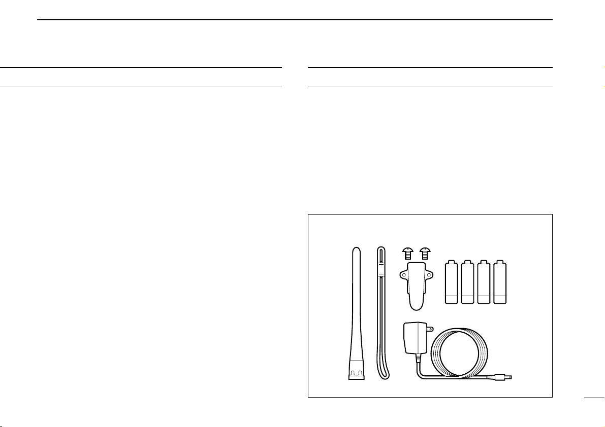
Accessories included with the receiver:
Qty.
q Antenna............................................................................1
w Handstrap.........................................................................1
e Belt clip (with 2 screws)....................................................1
r Wall charger*....................................................................1
t Ni-Cd batteries .................................................................4
* Not supplied with some versions.
ii
Page 4

TABLE OF CONTENTS
IMPORTANT .....................................................................................i
EXPLICIT DEFINITIONS ..................................................................i
CAUTIONS .......................................................................................i
UNPACKING....................................................................................ii
TABLE OF CONTENTS ..................................................................iii
OPERATING THEORY ...................................................................iv
OPERATING NOTES...................................................................... iv
1 PANEL DESCRIPTION.........................................................1 – 6
■ Front and side panels ............................................................................1
■ Top panel ...............................................................................................2
■ Function display ..................................................................................... 3
■ Keypad .................................................................................................. 5
2 Ni-Cd BATTERIES AND ACCESSORIES............................ 7 – 9
■ Charging Ni-Cd batteries .......................................................................7
■ Charging precautions ............................................................................ 7
■ About Ni-Cd batteries ............................................................................ 7
■ Battery installation ................................................................................. 8
■ Charging connections ............................................................................8
■ Accessory attachment ........................................................................... 9
3 BASIC OPERATION ......................................................... 10 – 22
■ General ................................................................................................10
■ Selecting VFO mode ........................................................................... 10
■ Selecting a receive mode .................................................................... 12
■ Selecting a tuning step ........................................................................ 13
■ Tuning a frequency (via the keypad) ................................................... 14
■ Tuning a frequency (via the [DIAL]) .....................................................15
■ Dial select steps .................................................................................. 16
■ Band scope function ............................................................................17
■ Listening example 1 ............................................................................. 19
■ Listening example 2 ............................................................................. 21
4 MEMORY MODE .............................................................. 23 – 34
■ General ................................................................................................23
■ Selecting memory mode ......................................................................23
■ Setting a bank and memory channel ...................................................24
■ Programming a memory channel—1 ...................................................25
■ Programming a memory channel—2 ...................................................26
■ Programming a memory channel—3 ...................................................27
■ Programming example 1 ..................................................................... 29
■ Programming example 2 ..................................................................... 30
■ Programming example 3 ..................................................................... 31
■ Memory copy .......................................................................................33
■ Copying example 1 ..............................................................................34
■ Copying example 2 ..............................................................................34
5 SCANNING OPERATION ................................................. 35– 46
■ General ...............................................................................................35
■ Before scanning ................................................................................... 37
■ Full scan .............................................................................................. 39
■ Memory scan .......................................................................................39
■ Program scan ...................................................................................... 40
■ Auto memory write scan ......................................................................41
■ BANK scan .......................................................................................... 43
■ Mode select scan ................................................................................. 44
■ Skip function ........................................................................................45
■ SIGNAVI function................................................................................. 46
6 PRIORITY WATCH ........................................................... 47 – 49
■ General ...............................................................................................47
7 EASY MODE ............................................................................ 50
■ General ................................................................................................50
■ EASY mode operation ........................................................................50
8 EDIT FUNCTION ..............................................................51–58
iii
Page 5

TABLE OF CONTENTS
OPERATING THEORY
■ General ................................................................................................51
■ Memory channel edit ........................................................................... 51
■ Program scan channel edit ..................................................................55
■ EASY mode channel edit ..................................................................... 55
■ Program scan or EASY mode channel edit .........................................57
9 SET MODE .......................................................................59–62
■ General ...............................................................................................62
10 OTHER FUNCTIONS ........................................................63–71
■ Low battery indicator ........................................................................... 63
■ AFC function ........................................................................................63
■ Monitor function ...................................................................................64
■ Lock function ....................................................................................... 64
■ ATT function ........................................................................................ 65
■ NB/ANL function ..................................................................................65
■ Sleep timer .......................................................................................... 66
■ User TS setting ....................................................................................66
■ Memory search function ...................................................................... 67
■ Auto mode and TS function .................................................................69
■ Resetting the CPU ...............................................................................70
■ Data cloning ........................................................................................ 71
11 ALPHANUMERIC KEY ASSIGNMENT ...................................72
12 CONTROL COMMANDS .................................................. 73 – 74
■ General ................................................................................................73
■ Data format ..........................................................................................73
■ Command table ................................................................................... 73
13 TROUBLESHOOTING ......................................................75–76
14 SPECIFICATIONS ................................................................... 77
15 OPTIONS ................................................................................. 78
Electromagnetic radiation which has frequencies of 20,000
Hz (20 kHz*) and above is called radio frequency (RF) energy
because it is useful in radio transmissions. The IC-R10 receives RF energy from 0.5 MHz to 1300 MHz* and converts it
into audio frequency (AF) energy which in turn actuates a
loudspeaker to create sound waves. AF energy is in the
range of 20 to 20,000 Hz.
*kHz is an abbreviation of kilohertz or 1000 hertz, MHz is abbreviation
of megahertz or 1,000,000 hertz, where hertz is a unit of frequency.
OPERATING NOTES
The IC-R10 may receives its own oscillated frequency, resulting in no reception or only noise reception, on some frequencies.
The IC-R10 may receive interference from extremely strong
signals on different frequencies or when using an external
high-gain antenna.
iv
Page 6
1
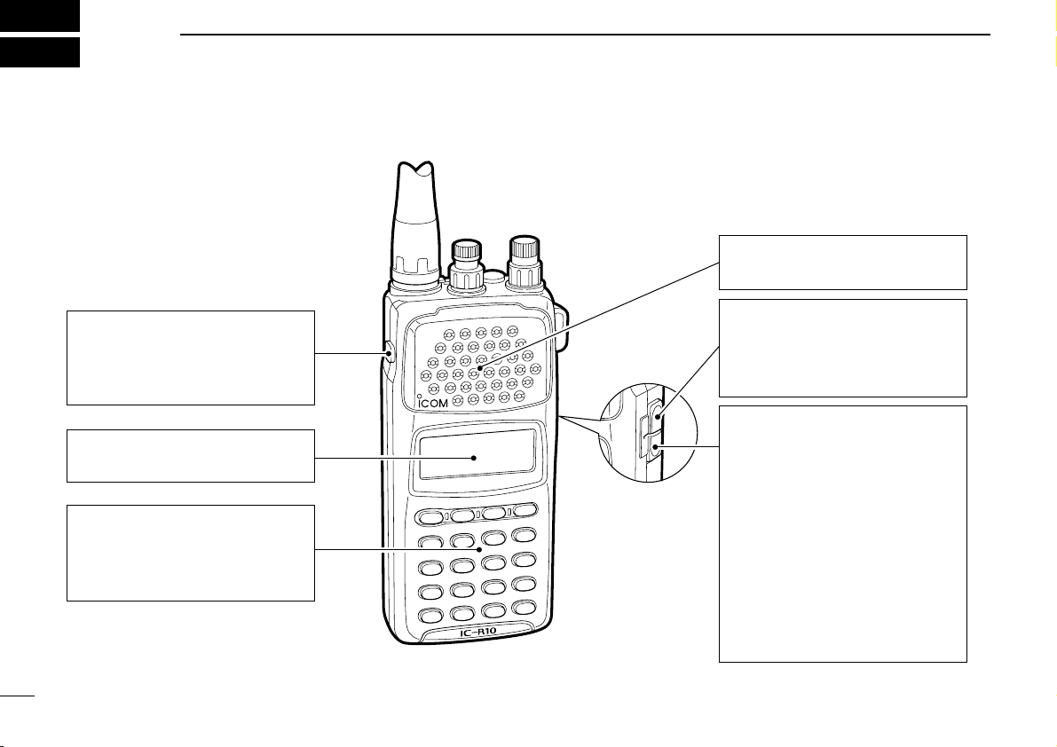
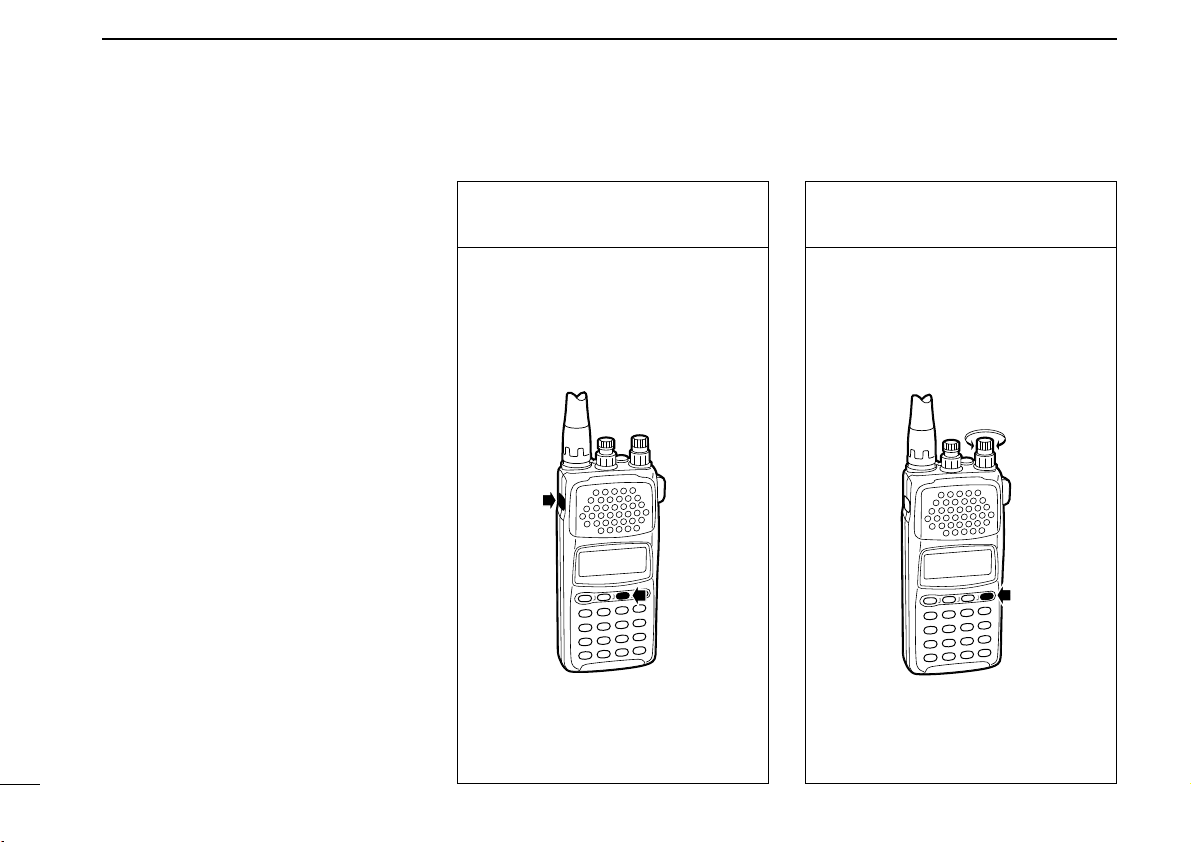
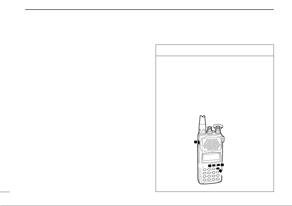
FUNCTION SWITCH (pgs. 5, 6)
While pushing [FUNC], the secondary functions of switches and
controls can be accessed.
FUNCTION DISPLAY (p. 3)
Indicates the operating condition.
KEYPAD (pgs. 5, 6)
Numeral and other function keys
for tuning and activating functions.
SPEAKER
Emits the receive audio.
CI-V JACK (p. 73)
Connect the optional OPC-478
CLONING CABLE for remote
control or data cloning.
EXTERNAL DC POWER JACK
(p. 8)
Connect the supplied wall charger for charging the installed Ni-Cd
battery cells.
Be careful of overcharging!
Operation with an external DC
power source simultaneously
charges the installed batteries.
When [CHARGE] switch is ON,
see p. 8.
PANEL DESCRIPTION
■ Front and side panels
1
Page 7
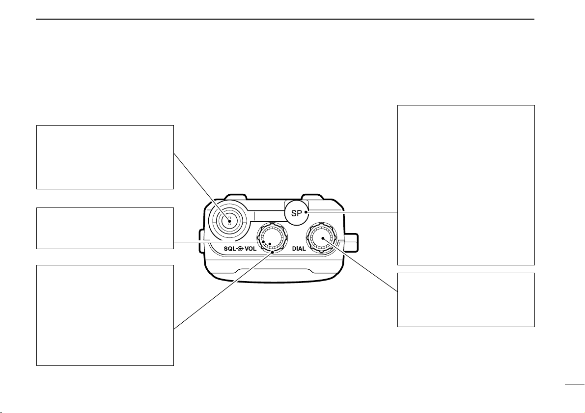
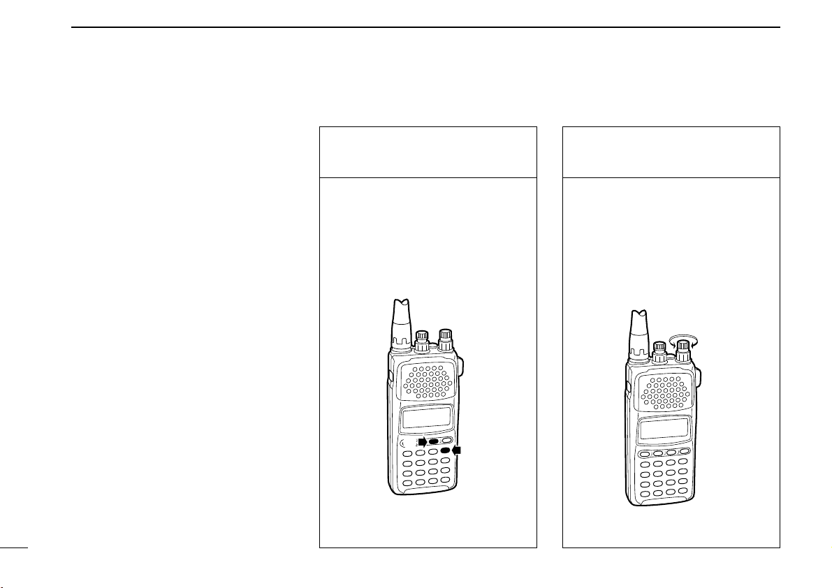
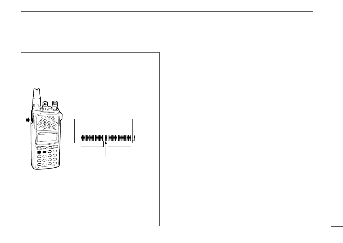
■ Top panel
ANTENNA CONNECTOR (p. 9)
Connects the supplied flexible
antenna. Be careful when connecting an external antenna
(See Operating Notes, p. iv).
VOLUME CONTROL [VOL]
(p. 10)
Adjusts the audio output level.
SQUELCH CONTROL [SQL]
(p. 11)
➥Varies the squelch threshold
point for audio mute.
• Pushing [MONI] opens the
squelch momentarily.
➥Varies the RF gain in LSB,
USB and CW modes.
EXTERNAL SPEAKER JACK
[SP]
Connect an 8 ohm optional
speaker or an earphone, if desired.
The internal speaker will not
function when either option is
connected.
Connect the optional OPC478/479
CLONING CABLE for
cloning from a PC or another ICR10 (p. 71).
TUNING CONTROL [DIAL]
Used to set an operating frequency (p. 15), memory channel
(p. 24), etc.
PANEL DESCRIPTION
1
2
Page 8
1
AT TVSCEASYVFOMEMO
AFCCWUSBLSBAMWFM
qw e r uty i o!0
!1
PANEL DESCRIPTION
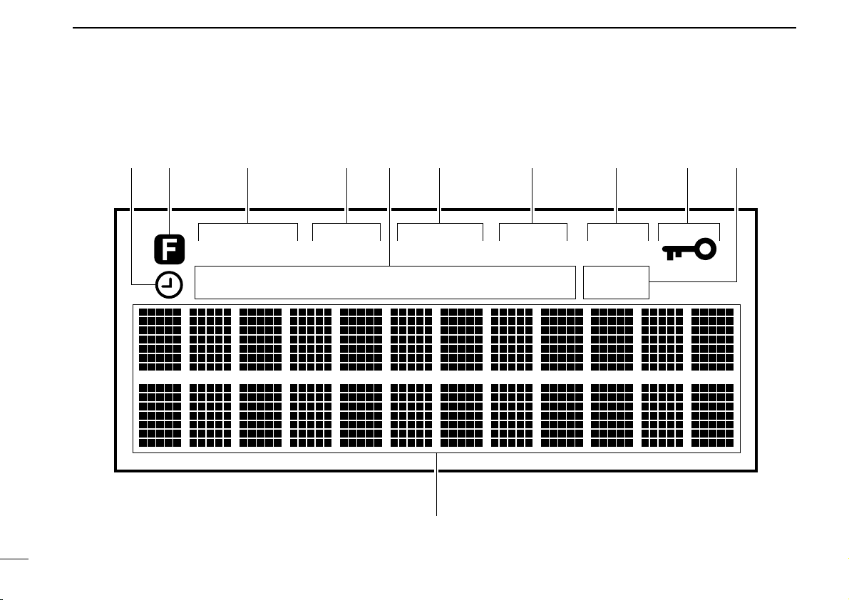
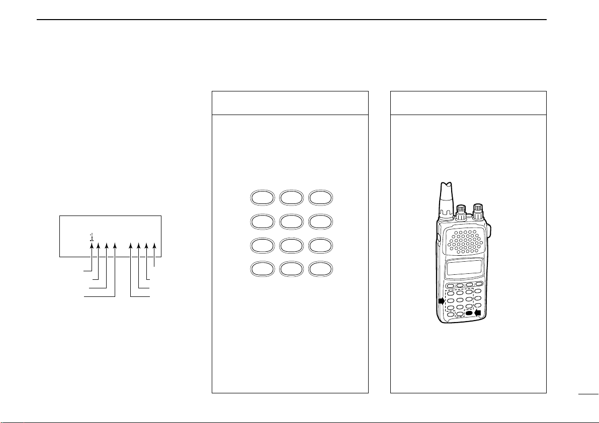
■ Function display
3
Page 9

PANEL DESCRIPTION
1
q SLEEP TIMER INDICATOR
Appears while the sleep timer is activated (p. 66).
w FUNCTION INDICATOR
Appears while the function ([FUNC]) switch is pushed.
e MEMORY MODE INDICATOR
Appears while in memory mode (p. 23).
r VFO MODE INDICATOR
Appears while in VFO mode (p. 11).
t RECEIVE MODE INDICATOR
Indicates the selected receive mode (p. 12).
y EASY MODE INDICATOR
Appears while in easy mode (p. 50).
u VSC INDICATOR
Appears while the VSC function is turned ON (p. 38).
i ATTENUATOR INDICATOR
Appears while the attenuator is turned ON (p. 65).
o AFC INDICATOR
Appears while the AFC function is turned ON (p. 63).
!0 LOCK INDICATOR
Appears while the lock function is activated (p. 64).
!1 MULTI-FUNCTION DOT MATRIX
Indicates the following items:
Opening message (p. 10)
Receive frequency (p. 11)
Tuning steps (p. 13)
Band scope (p. 17)
Memory bank and channel number (p. 23)
Memory name (p. 31)
Memory bank name (p. 32)
Programmable scan edges and name (p. 40)
Priority frequency (p. 49)
SET mode contents (p. 59)
Signal strength indicator
4
Page 10

1
PANEL DESCRIPTION
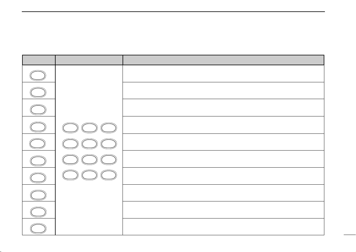
■ Keypad
KEY PRIMARY FUNCTION SECONDARY FUNCTION (while pushing [FUNC])
POWER
Push for 1 sec. to toggle power ON and OFF. Opening message appears for 1 sec. after power ON
(p. 10).
Not available
MONI
TS
MODE
SET
CLR
MW
V/M
DIAL SEL
SCAN
SEARCH
EASY
LOCK
EDIT
NB/ANL
ENT
Push and hold this switch to force the squelch open (p. 64).
Selects a receive mode: FM, AM, USB, LSB, CW or WFM
(p. 12).
Clears numeric key input (p. 14).
Stops scanning (p. 39).
Toggles VFO or MEMORY mode
(pgs. 11, 23).
Starts/stops scanning (p. 39). In VFO mode: selects a dial select step (p. 16).
Selects EASY mode (p. 50). Selects memory channel name search mode (p. 67).
Selects memory edit mode. (except when in VFO mode; p.
51).
In VFO mode: enters the selected receive frequency (p. 14).
In MEMORY mode: enters the selected memory channel by
the memory search function (p. 68).
Not available
Selects tuning step set mode (p. 13).
Selects SET mode (p. 59).
In VFO mode: writes to a memory channel
(p. 29).
ORY mode: transfers memory contents to VFO mode
or copies to another channel
(p. 33).
In MEM-
(p. 33)
Locks all switches and controls electronically except [VOL],
[SQL], [FUNC], [POWER] and [MONI]
(p. 64).
Activates the noise blanker while in SSB and CW mode, or
the ANL function while in AM mode
(p. 65).
5
Page 11
PANEL DESCRIPTION
KEY PRIMARY FUNCTION SECONDARY FUNCTION (while pushing [FUNC])
BSCOPE
1
VSC
2
SLEEP
3
PROG-S
4
AMWS
5
SIGNAVI
6
MODE-S
7
BANK-S
8
PRIO
9
ATT
0
SLEEP
BSCOPE
PROG-S5AMWS6SIGNAVI
MODE-S
AFC0ATT
VSC
1
4
7
2
BANK-S
.
PRIO
8
NB/ANL
ENT
When FM receive mode is selected in VFO mode: toggles the band scope function (p. 17).
Toggles the VSC function ON and OFF (p. 38).
Selects the sleep timer conditions (p. 66).
In VFO mode: sets program scan edge frequencies for programmed scan (p. 40).
3
In VFO mode: sets program scan edge frequencies for auto memory write scan (p. 41).
In VFO mode: toggles the signal navigator function ON/OFF for full, programmed or auto
9
memory write scan
In MEMORY mode: sets the receive mode for mode select scan
In MEMORY mode: sets the BANK for bank scan
(p. 46).
(p. 44).
(p. 43).
Starts/stop priority watch (p. 49).
Toggles the attenuator ON/OFF (p. 65).
1
6
Page 12
2
RBRC
RBRC
Ni-
Cd
Ni-Cd BATTERIES AND ACCESSORIES
■ Charging Ni-Cd batteries
The supplied Ni-Cd batteries are rechargeable and can be
charged approx. 300 times. Charge the batteries before first
operating the receiver or when the batteries become exhausted.
If you want to be able to charge the batteries more than 300
times, the following points should be observed:
1. Avoid overcharging. The charging period should be less
than 48 hours.
2. Use the batteries until they become almost completely exhausted under normal conditions. We recommend battery
charging just after receiving becomes impossible.
■ Charging precautions
NEVER attempt to charge dry cell batteries. This will cause
internal liquid leakage and damage the receiver.
NEVER connect two or more chargers at the same time.
Charging may not occur under temperatures of 10°C (50°F)
or over temperatures of 40°C (104°F).
■ About Ni-Cd batteries
Ni-Cd battery life
If your Ni-Cd batteries seems to have no capacity even after
being fully charged, completely discharge them by leaving the
power ON overnight. Then, fully charge the Ni-Cd batteries
again. If the Ni-Cd batteries still do not retain a charge (or
very little), new batteries must be purchased.
Recycling information (U.S.A. only)
The product that you purchased contains
rechargeable batteries. The batteries are recyclable. At the end of their useful life, under vari-
ous state and local laws, it may be illegal to
dispose of these batteries into the municipal waste stream.
Call 1-800-8-BATTERY for battery recycling options in your
area or contact your dealer.
7
Page 13
Ni-Cd BATTERIES AND ACCESSORIES
to [DC]
BC-110A/E/D/V*
*Not supplied with
some versions.
CP-12L (optional)
To cigarette lighter
socket
OPC-254L (optional)
To power supply
(4.8–13.5 V DC)
Black
White
CHARGE
OFF ON
2
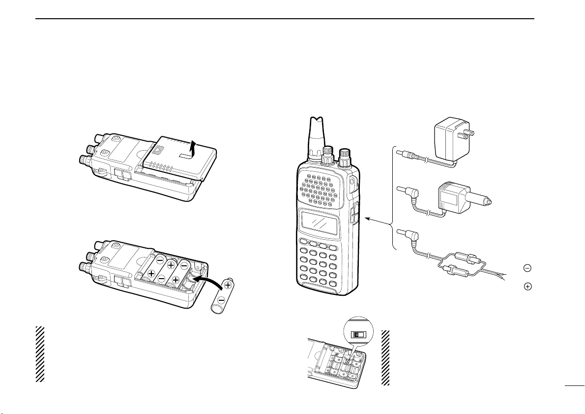
■ Battery installation
Install 4 AA (R6) size batteries as illustrated below.
Remove the cover from the receiver.
Install 4 AA (R6) size dry cell, alkaline or the supplied Ni-Cd
batteries into the receiver.
CAUTION: Make sure the polarity of the batteries is correct before installing. Reverse polarity may damage the receiver.
NOTE: DO NOT use different types of batteries at the
same time otherwise the receiver may not work properly.
■ Charging connections
Confirm that the [CHARGE] switch is ON, then connect the
supplied wall charger via an AC outlet as shown below.
CAUTION: Make sure the
[CHARGE] switch is in the OFF position when operating the receiver
with one of the above power supplies.
8
Page 14
2
Ni-Cd BATTERIES AND ACCESSORIES
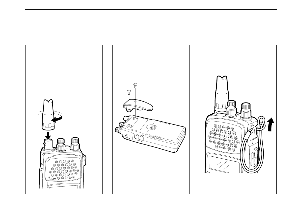
■ Accessory attachment
Antenna
Insert the supplied antenna into the
antenna connector and rotate the antenna as shown in the diagram
below. Keep the jack cover attached
when jacks are not in use to avoid
bad contacts.
Belt clip
Attach the belt clip using the supplied
screws.
Conveniently attaches to your belt.
Handstrap
Attach the handstrap as shown in the
diagram below. Facilities carrying.
9
Page 15
BASIC OPERATION
VFO
FM
Presented
by ICOM
Opening message as
above is displayed on the
multi-function display.
3
■ General
Operating the IC-R10 is easy. However,
in order to get the most out of its operating potential, please go through the
following procedures, step-by-step.
Then, try the examples contained at the
end of this chapter.
What is VFO?
The IC-R10 has several operating
modes, each of which has its own distinct functions. VFO (Variable
Frequency Operation) is one of these
modes.
VFO mode is used to change the operating frequency, receive mode, tuning
step, etc. Therefore, for most every day
operations of the receiver, you will be
using VFO mode.
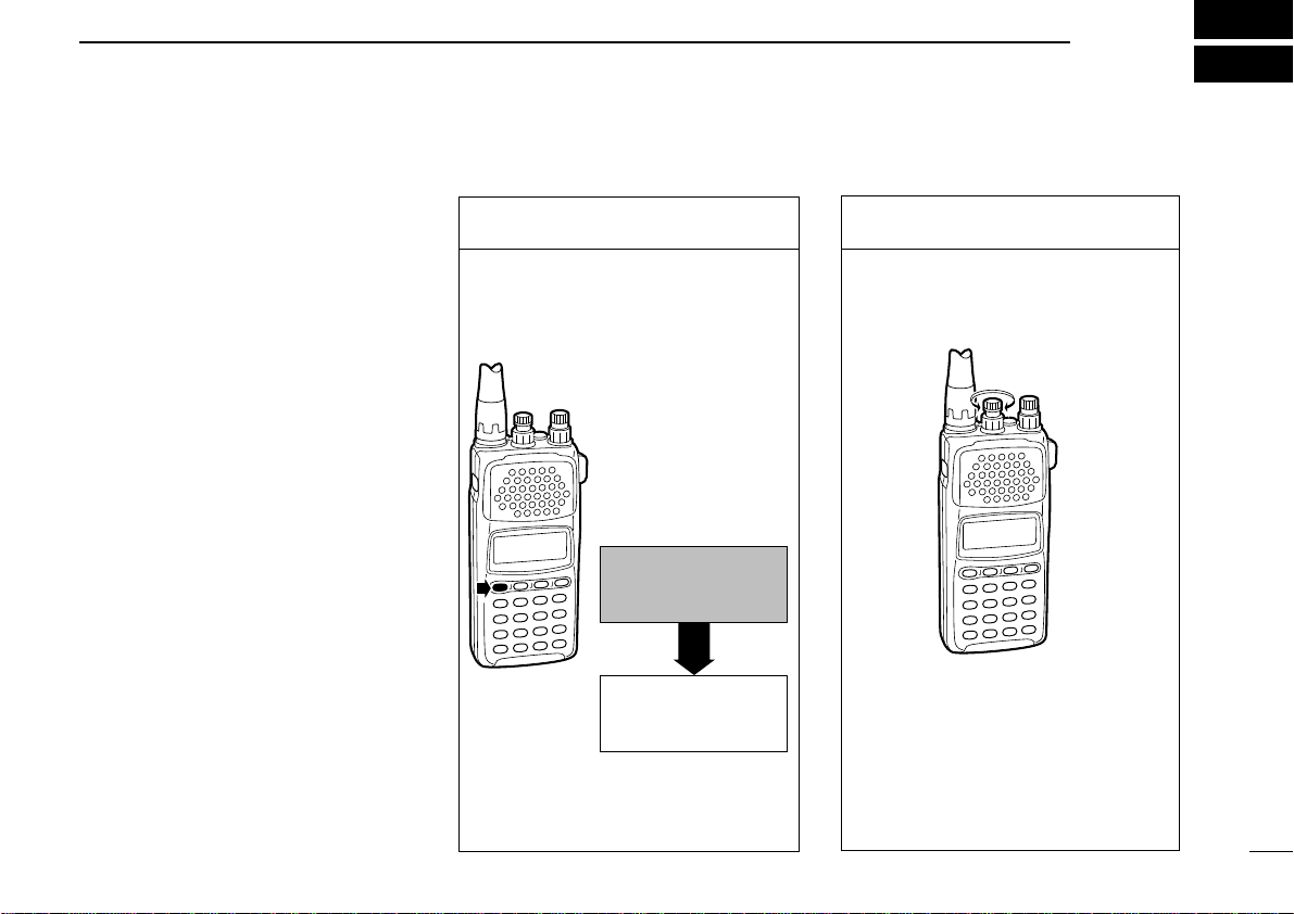
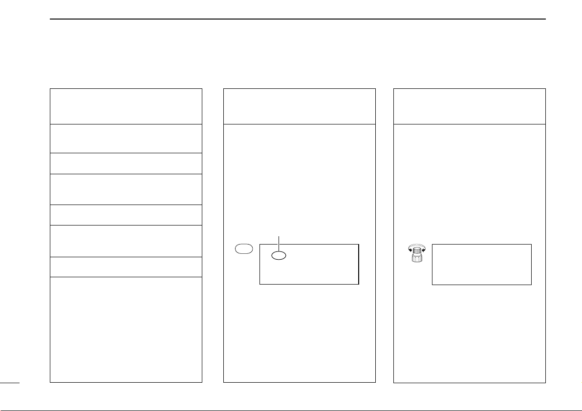
■ Selecting VFO mode
1. Turn power ON
Push [POWER] for 1 sec. to turn
power ON.
•Opening message is displayed for 1
sec.
2. Adjust the volume
Adjust the audio to a suitable level
using [VOL].
Check the squelch position (see next
page) or VSC function setting (p. 38)
if no audio is emitted.
10
Page 16
3
BASIC OPERATION
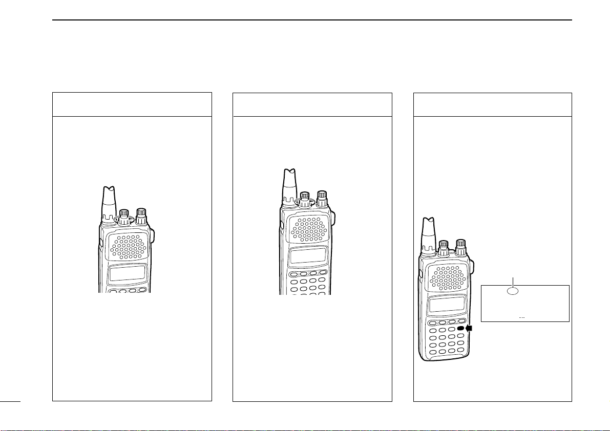
3. Adjust the squelch
Rotate [SQL] maximum counterclockwise, then rotate it clockwise
until audio is just muted when receiving no signal for FM, WFM or AM
mode. (see right page)
What is squelch?
A squelch circuit allows you to mute
undesired noise while receiving no
signal and emit audio while receiving
signals. This provides quiet standby.
The [MONI] switch changes the
squelch setting. This is useful for
weak signal reception (p. 64).
3-1. Adjust the RF gain
Rotate [SQL] maximum counterclockwise, to adjust RF gain to optimum level.
What is RF gain?
RF gain controls receive sensitivity
gain—reduce the gain when you
don’t want to receive very weak signals or when excessively strong interfering signals are being received,
etc.
4. Select VFO mode
When MEMORY mode is selected,
push [V/M] to select VFO mode.
When SET or TS set mode is selected, push [CLR] to select VFO
mode.
• The VFO indicator appears.
VFO indicator
VFO
FM
144.0000
11
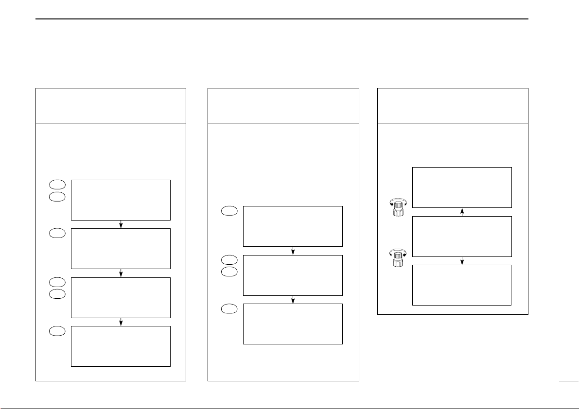
Page 17
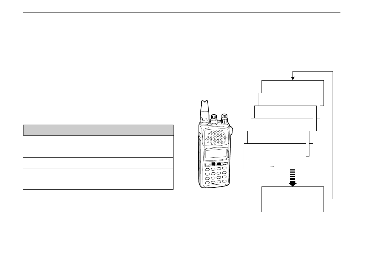
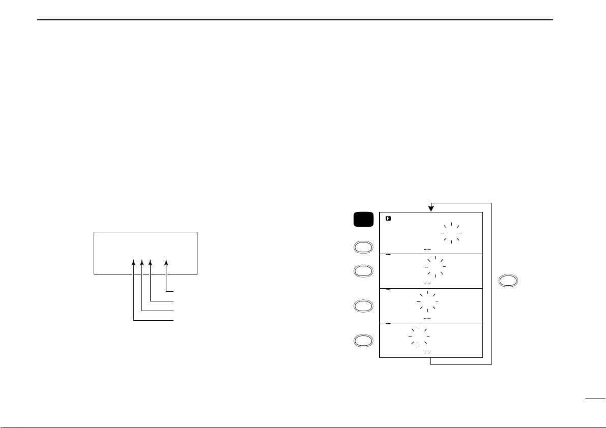
■ Selecting a receive mode
What are receive modes?
Radio signals can be propagated in a variety of ways (or
modes). Each mode has its own physical properties that determine to some degree its uses.
The IC-R10 receives the 6 most common modes: AM, FM,
WFM, USB, LSB and CW. When you want to tune a station,
you MUST set the receive mode first. The table below shows
common uses for each mode.
MODE COMMON USAGE
AM amateur, aviation, broadcasting
FM amateur, utility
WFM TV broadcasting, FM broadcasting
BASIC OPERATION
VFO
FM
144.0000
VFO
WFM
144.0000
VFO
AM
144.0000
VFO
LSB
144.0000
VFO
USB
144.0000
VFO
CW
144.0000
3
USB, LSB commercial, amateur, short wave radio
CW commercial, amateur
Major symptoms of incorrect receive mode
Distorted sound
Sudden interruption in reception
Noise only
Noise with weak reception
Low or unstable signal strength indicator value
When programmed
(see p. 69)
VFO
FM
AUTO MODE
144.0000
12
Page 18
3
q
w
BASIC OPERATION
■ Selecting a tuning step
What are tuning steps?
Tuning steps are the frequency change
increments when you rotate the tuning
control or operate a scan. The following
steps are available: 0.1, 0.5, 1, 5, 6.25,
8, 9, 10, 12.5, 15, 20, 25, 30, 50, 100
kHz and user programmable tuning
steps (p. 66).
It is important to set the proper tuning
step for the type of station you want to
listen to. Some tuning steps are determined by frequency band or receive
mode and others are set by tradition.
Generally speaking, if you set a tuning
step smaller than that needed you will
still be able to tune a station you want
(or scan it), however, tuning (or scanning) will not be efficient. On the other
hand, if you select a tuning step which
is too large, you may not be able to find
the station you are looking for.
Consult local listings.
1. Call up the tuning step
set mode
Once you have selected VFO mode
and the desired receive mode, while
pushing [FUNC], push [
(MODE)TS].
2. Select the tuning step
q Rotate [DIAL] to select the desired
tuning step.
w Push [CLR] to return to VFO
mode after the selection.
13
Page 19
■ Tuning a frequency (via the keypad)
VFO
FM
10 MHz 10 kHz
100 MHz
100 kHz
1 kHz
100 Hz
1 MHz
1 GHz
300 .0000
BASIC OPERATION
3
When you know the exact frequency
you want to listen to, the quickest way
to tune it is by direct keypad entry.
Remember that the frequency must be
between 0.5 MHz and 1300 MHz.
The diagram below shows the correlation between the function display frequency digits and the frequency.
1. Select the frequency
Select VFO mode and the receive
mode in advance then:
Push the numeral keys in the same
order as the frequency you want to
tune (including the decimal key).
SLEEP
BSCOPE
PROG-S5AMWS6SIGNAVI
MODE-S
•If you make a mistake, push [CLR] and
start again.
VSC
2
1
4
BANK-S
8
7
AFC0ATT
.
3
PRIO
9
NB/ANL
ENT
2. Enter the frequency
When the frequency you want is displayed:
Push [ENT] (or numeral keys for the
0.1 kHz digit) to enter it.
•When you select a frequency outside of
the allowed range, the display will revert
back to the previously displayed frequency.
14
Page 20
3
BASIC OPERATION
■ Tuning a frequency (via the dial)
When you want to listen to frequencies
near the displayed frequency, the easiest way to tune them is with the tuning
dial.
All signals have what is called an “occupied bandwidth.” They will be received as long as the receiver is tuned
anywhere within this bandwidth. Even
though the frequency received may not
be the central frequency, the tuning
step should be made as small as possible (0.5 or 5 kHz) and the receiver
tuned to the point of greatest signal
strength indicator deflection.
To change frequencies faster than the
tuning step, use the dial select function
(p. 16).
1. Select VFO mode and
a receive mode
q Push [CLR] or [V/M] to select VFO
mode.
w Push [MODE] to select a receive
mode.
e Set tuning step if desired (p. 14).
w
2. Tune a frequency
Rotate [DIAL] to change the frequency.
•The frequency changes in increments
determined by the tuning step.
•To change the frequency faster, use the
dial select function (p. 16).
q
15
Page 21
BASIC OPERATION
VFO
FM
144.0000
VFO
FM
144.0000
VFO
FM
144.0000
VFO
FM
144.0000
FUN C
SCAN
DIAL SEL
SCAN
DIAL SEL
SCAN
DIAL SEL
SCAN
DIAL SEL
SCAN
DIAL SEL
+
VFO
FM
144.0000
100 kHz
1 MHz
10 MHz
100 MHz
3
■ Dial select steps
What are dial select steps?
When tuning with the dial, if you want to change the frequency faster than the selected tuning step can, use the dial
select function.
A dial select step is an increment of frequency change much
like a tuning step is. Unlike a tuning step however, a dial select step has no relation to the type of station you want to tune
or to the scan operations.
Dial select steps are available for:
Changing the frequency with the dial select step
In VFO mode:
Push and hold [FUNC], then rotate [DIAL].
To change the dial select step:
While pushing [FUNC], push [
eral times until the frequency digit you want to change
flashes.
(SCAN)DIAL SEL] one or sev-
16
Page 22
3
BASIC OPERATION
■ Band scope function
What is the band scope function?
The band scope detects signal availability in the range of ±5
channels (up to ±100 kHz) from the displayed frequency, and
displays the result on the multi function dot-matrix display.
This gives you a visual reference of current band conditions.
In this case, channel refers to sweep step or channel space
according to the set tuning step. For example, when the tuning step is set to 5 kHz, the band scope detects 25 kHz above
and below the displayed frequency, then displays the result
on the LCD.
When the tuning step is set above 20 kHz, the band scope
function automatically changes its sweep step to 20 kHz.
However, when the sweep step is changed to 20 kHz, the
tuning step remains the same.
Also, when a user-programmable tuning step is selected, the
band scope function automatically selects the 20 kHz sweep
step.
Preparation
The band scope function is activated only when FM receive
mode is selected in VFO mode.
q Push [V/M] to select VFO mode. (p. 11)
w Push [MODE] one or more times to select FM mode.
(p. 12)
e While pushing [FUNC], push [
r Rotate [DIAL] to select the tuning/sweep step.
t Push [CLR] to return to VFO mode.
r
e
we
(MODE)
t
q
TS]
17
Page 23
Set band scope function
q While pushing [FUNC], push [(1)BSCOPE].
VFO
FM
144.0000
lower freq.
higher freq.
displayed freq.
signal
strength
BASIC OPERATION
3
Repeat the above step or push [CLR] to turn OFF the band
scope function.
18
Page 24
3
BASIC OPERATION
■ Listening example 1 — television broadcast in WFM mode
1. Turn power ON
Push [POWER] for 1 sec. to turn
power ON.
2. Select VFO
Push [CLR] or [V/M] to select VFO
mode.
3. Adjust volume
Rotate [VOL] to obtain the desired
level of audio output.
4. Adjust squelch
Rotate [SQL] fully counterclockwise,
then clockwise until the audio noise
just disappears.
5. Select the receive
mode
Television sound is broadcast in
WFM mode. If the receiver is not already in WFM mode:
Push [MODE] one or more times until
WFM appears in the function display.
Appears
MODE
WFM
VFO
144.0000
6. Select the tuning step
In most countries* television stations
are spaced about 50 kHz apart. To
select the 50 kHz tuning step:
While pushing [FUNC], push
[
(MODE)TS], then rotate [DIAL] until
the function display shows “50 kHz”.
Push [CLR] after setting to return to
VFO mode.
VFO
WFM
SET TS
[DIAL]
TS 50 .00kHz
TS 50 .00kHz
*Check listings for your area.
19
Page 25
BASIC OPERATION
59.3000
VFO
WFM
59.2500
VFO
WFM
59.2000
VFO
WFM
[DIAL]
[DIAL]
3
(Example 59.75 MHz)
7. Tune the station
Use the keypad to enter the frequency — (example 59.75 MHz).
[Example]
ENT
5
9
.
7
5
VFO
WFM
VFO
WFM
59.
VFO
WFM
59. 75
VFO
WFM
59.7500
. 59
(Example 59.25 MHz)
7-1. Tune the station
Enter the frequency from the 100 kHz
digit when you want to change below
the 1 MHz digit only — (example
from 59.75 MHz to 59.25 MHz).
[Example]
.
2
5
ENT
WFM
WFM
WFM
VFO
VFO
VFO
59.
59. 25
59.2500
8. Use the tuning dial
Rotate [DIAL] to search for nearby
stations above and below the tuned
frequency.
NOTE: WFM and regular FM share the
same circuit. Depending on the receive
condition, this may result in distortion.
In such cases, try lowering the frequency 30–50 kHz.
20
Page 26
3
BASIC OPERATION
■ Listening example 2 — airband broadcast in AM mode
1. Turn power ON
Push [POWER] for 1 sec. to turn
power ON.
2. Select VFO
Push [CLR] or [V/M] to select VFO
mode.
3. Adjust volume
Rotate [VOL] to obtain the desired
level of audio output.
4. Adjust squelch
Rotate [SQL] fully counterclockwise,
then clockwise until the audio noise
just disappears.
5. Select the receive
mode
Airband communications are in AM
mode. If the receiver is not already in
AM mode:
Push the [MODE] switch one or more
times until AM appears in the function
display.
Appears
MODE
AM
VFO
144.0000
6. Select the tuning step
Tuning steps for the airband are usually 25 kHz*. To set the 25 kHz tuning step:
While pushing [FUNC], push
[
(MODE)TS], then rotate [DIAL] until
“25 kHz” appears in the function display.
VFO
AM
[DIAL]
SET TS
TS 25 .00kHz
*Check listings for your area.
21
Page 27

BASIC OPERATION
VFO
AM
118 .
ENT
2
5
9
.
VFO
AM
118. 925
VFO
AM
118 .9250
VFO
AM
118.9000
VFO
AM
118 .9250
VFO
AM
118 .9500
[DIAL]
[DIAL]
3
(Example 118.00 MHz)
7. Tune the station
Enter a frequency of 118.0000 MHz*
using the keypad (p. 14).
1
1
8
ENT
*Check listings for your area.
VFO
AM
VFO
AM
118 .0000
118
(Example 118.925 MHz)
7-1. Tune the station
Enter the frequency from the 100 kHz
digit when you want to change below
the 1 MHz digit only — (example
from 118 MHz to 118.925 MHz).
8. Use the tuning dial
Rotate [DIAL] to search for nearby
stations above and below the tuned
frequency.
22
Page 28

4
MEMORY MODE
■ General
What is memory mode?
MEMORY mode is the second operating mode—the first
being VFO mode. MEMORY mode is used to store oftenused frequencies, their receive modes, attenuator settings
(p. 65), as well as skip information for scanning (p. 56). This
provides convenient recall and scanning capabilities. Also,
frequencies are receivable in MEMORY mode which means
you can listen to received signals while you are in MEMORY
mode.
The IC-R10 has 1000 memory channels for your convenience. They are divided into 18 banks: BANKS A to P contain 50 channels each for normal usage, while BANKS Q and
R contain 100 channels each for auto-memory write scan
(p. 41) and program skip scan (p. 45), respectively.
Each BANK and memory channel has BANK or memory
name capabilities, for convenience. BANK names can be up
to 10 characters; channel names up to 8 characters.
Programmed contents and names can be easily copied to
other channels using the memory copy function (p. 33) and
easily edited using the EDIT function (p. 51).
■ Selecting MEMORY mode
Select MEMORY mode
Push [V/M] to select MEMORY mode.
•“MEMO” appears in the function display.
• Push [V/M] again to return to VFO mode.
Appears
MEMO
FM
A00 144 .0000
23
Page 29

■ Selecting a BANK and memory channel
MEMORY MODE
4
Selecting a BANK
channel
When your desired memory channel
is not stored or you do not want to
store a frequency in the displayed
BANK, you must change the BANK
number.
While pushing [FUNC], rotate [DIAL].
Selecting a memory
channel—1
If you want to recall a memory channel which has been memorized, this
is the easiest way.
Rotate [DIAL].
Selecting a memory
channel—2
If you remember the memory channel
number you want to recall, this is the
fastest way to recall it.
Enter the full 2-digit memory channel
number via the keypad.
Also, when you want to recall a blank
channel for programming, you have
to enter a channel number via the
keypad.
24
Page 30

4
MEMORY MODE
■ Programming a memory channel — 1
This is the quickest way to memorize a
received frequency, along with its receive mode and other information.
When you memorize the frequency in
this way, the previously memorized data
is replaced with the new data. If you do
not want to lose the previously memorized data, select a blank channel number before programming (p. 24).
1. BANK and memory
channel setting
q Select MEMORY mode (p. 23).
w Set the BANK and memory chan-
nel number (p. 24) you want to
program to.
2. Setting other
information
q Select VFO mode (p. 11).
w Set the frequency and receive
mode (p. 12) you want in VFO
mode.
3. Programming
While pushing [FUNC], push
[
(V/M)MW] to program the data.
•When programming is successfully
completed, 3 beeps sound.
25
Page 31

■ Programming a memory channel — 2
MEMORY MODE
4
This is the simplest method to memorize the received frequency along with
its receive mode and other information.
1. Setting receive
conditions
q Select VFO mode (p. 11).
w Set the frequency and receive
mode (p. 12).
2. BANK and memory
channel setting
While pushing
[FUNC], push
[
(V/M)MW].
3. BANK and memory
channel setting
q While pushing [FUNC], rotate
[DIAL] to select the BANK you
want to program into.
w Rotate [DIAL] to select the mem-
ory channel you want to program.
qqw
4. Programming
While pushing [FUNC], push
[
(V/M)MW] for 2 sec. to program the
data.
•When programming is successfully
completed, 3 beeps sound and VFO
mode is automatically selected.
26
Page 32

4
MEMORY MODE
■ Programming a memory channel — 3
This is the easiest way to memorize the received frequency,
mode and other information along with memory, BANK
names, scanning condition, etc. in one operation.
1. Set up
q Set the frequency you want to program in VFO mode.
MW] to enter mem-
w While pushing [FUNC], push [
ory write mode.
(V/M)
2. BANK and memory channel setting
q While pushing [FUNC], rotate [DIAL] to select the BANK
you want to program (p. 24).
w Rotate [DIAL] or push 2 digit keys to select the memory
channel you want to program (p. 24).
3. Programming details
q Push [EDIT] to enter memory programming mode.
w Rotate [DIAL] or enter the alphanumeric characters via
the keypad to program a memory name.
• When you enter channel names with [DIAL] or a character assigned to the same key, push [ENT] before you enter the next
character to change the digit (see page 72 for alphanumeric
key assignments).
w
w
q
27
Page 33

MEMORY MODE
4
3. Programming details — cont.
e Push [EDIT], then rotate [DIAL] to select receive mode.
r Push [EDIT], then rotate [DIAL] to select the skip scan
condition.
t Push [EDIT], then rotate [DIAL] to select the attenuator
condition.
y Push [EDIT], then rotate [DIAL]
or enter alphanumeric characters to program a BANK name.
• When you enter channel names
with [DIAL] or a character assigned to the same key, push
[ENT] before you enter the next
character to change the digit (see
page 72 for alphanumeric key assignments).
y
3. Programming details — cont.
u Push [EDIT], to display your programmed frequency for
confirmation. When the correct frequency is displayed,
push [EDIT] for 2 sec. to return to VFO mode.
When you want to return to VFO mode immediately, push
[EDIT] for 2 sec. at any time.
28
Page 34

4
MEMORY MODE
■ Programming example 1 — (118.0250 MHz; AM to channel B07)
1. BANK and memory
channel setting
q Push [V/M] to select MEMORY
mode.
w While pushing [FUNC], rotate
[DIAL] to select BANK “B”.
B:
MEMO
FM
FUN C
+
[DIAL]
e Push [0] and [7] to enter the mem-
ory channel number.
0
7
MEMO
FM
B07 .
BLANK
"BLANK" appears when
the memory channel is not
programmed.
2. Data setting
q Push [V/M] to select VFO mode.
w Push [MODE] one or more times
to select AM mode.
MODE
AM
VFO
144.0000
e Push numeral keys or rotate
[DIAL] to set the frequency
118.0250 MHz.
1
1
8
.
0
2
5
ENT
VFO
AM
118 .
VFO
AM
118 .0250
3. Programming the data
While pushing [FUNC], push
[
(V/M)MW] for 2 sec.
29
Page 35

MEMORY MODE
■ Programming example 2 — (59.75 MHz; WFM to channel A45)
4
1. Setting the frequency
q Push [V/M] to select VFO mode.
w Push [MODE] one or more times
to select WFM mode.
MODE
WFM
VFO
144.0000
e Push numeral keys or rotate
[DIAL] to set the frequency to
59.75 MHz.
5
9
.
7
5
ENT
WFM
VFO
59.7500
2. Set the BANK and
memory channel
q While pushing [FUNC], push
[
(V/M)MW] to enter memory write
mode.
w While pushing [FUNC], rotate
[DIAL] to select BANK “A”.
FUN C
+
VFO
WFM
SET BANK
A:
[DIAL]
e Rotate [DIAL] select channel “45”
or push [4] and [5] to enter the
memory channel number.
VFO
WFM
SET CH NO .
[DIAL]
or
A45 BLANK
4
5
"BLANK" appears when
the memory channel is not
programmed.
3. Programming the data
While pushing [FUNC], push
[
(V/M)MW] for 2 sec.
30
Page 36

4
SET CH NAME
F01 E
3
[DIAL]
52
or
ENT
VFO
FM
VFO
SET BANK
F:
FUN C
[DIAL]
+
FM
VFO
121 .5000
ENT
2
1
1
5
.
FM
SET CH NAME
F01
EDIT
VFO
FM
VFO
SET CH NO .
F01 BLANK
[DIAL]
FM
MEMORY MODE
■ Programming example 3 — (121.5 MHz, EMER.,AM, SKIP: OFF, ATT: OFF, Aviation to channel F01)
31
1. Setting the frequency
q Push [V/M] to select VFO mode.
w Rotate [DIAL] or push numeral
keys to enter 121.5 MHz.
2. BANK and memory
channel setting
q While pushing [FUNC], push
[
(V/M)MW].
w While pushing [FUNC], rotate
[DIAL] to select BANK “F”.
e Rotate [DIAL] or push [0] then [1]
to select channel “01”.
3. Programming details
q Push [EDIT] to enter memory set-
ting mode.
w Rotate [DIAL] until the character
“E” appears then push [ENT] or
push [3] twice to enter the “E.”
e Rotate the [DIAL] then push [ENT]
to enter the characters ”M”, “E”,
“R” and “.” for memory names or
push numeral keys (see page 72
for alphanumeric key assignments).
Page 37

MEMORY MODE
4
3. Programming details
— cont.
t Push [EDIT] to change the re-
ceive mode item.
y Rotate [DIAL] to select AM mode,
then push [EDIT] to change the
item.
VFO
FM
[DIAL]
SET MODE
MODE:AM
u Rotate [DIAL] to select the OFF
position for SKIP setting, then
push [EDIT].
VFO
FM
SET SKIP
[DIAL]
SKIP: OFF
3. Programming details
— cont.
i Rotate [DIAL] to select the OFF
position for attenuator setting,
then push [EDIT].
VFO
FM
SET ATT
[DIAL]
ATT: OFF
o Rotate [DIAL] until the character
“A” appears, then push [ENT] or
push [2] once to enter “A”.
VFO
FM
SET B-NAME
[DIAL]
F:A
ENT
or
2
!0 Rotate [DIAL ]then push [ENT] to
enter the characters for BANK
names or push numeral keys (see
page 72 for alphanumeric key assignments).
3. Programming details
— cont.
!1 The display shows the pro-
grammed frequency for confirma-
tion; push and hold [EDIT] for 2
sec. if the frequency is correct.
• After pushing and holding [EDIT],
VFO mode is automatically selected.
EDIT
Push
for
2 sec.
VFO
AM
121 .5000
32
Page 38

4
MEMORY MODE
■ Memory copy
What is the memory copy function?
The memory copy function copies the contents (minus BANK
names) of the selected memory channel to VFO or to another
memory channel. This is quite useful when you want to
search for signals around the displayed frequency or when
you want to edit memory channels.
Copy to VFO mode
q Push [V/M] to select memory mode.
w Select the BANK and memory channel you want to copy
(p. 24).
e While pushing [FUNC], push
[
(V/M)MW] for 2sec.
Copy to the other memory channel
q Push [V/M] to select memory mode. (p. 23)
w Select the BANK and memory channel you want to copy
(p. 24).
e While pushing [FUNC], push [
r Set the BANK and channel number you want to copy to
(p. 24).
t While pushing [FUNC], push [
w
e
r
t
w
r
(V/M)MW].
(V/M)MW] for 2 sec.
w
r
e
qt
33
Page 39

MEMORY MODE
MEMO
WFM
A45 59.7500
59.7500
VFO
WFM
FUN C
V/M
MW
+
MEMO
AM
B07 118.0250
MEMO
AM
MEMORY COPY
FUN C
V/M
MW
+
MEMO
AM
SET BANK
F:Aviation
FUN C
[DIAL]
+
MEMO
AM
SET CH NO .
F02 BLANK
[DIAL]
MEMO
AM
F02 118.0250
FUN C
V/M
MW
+
4
■ Copying example 1
q Push [V/M] to select memory mode (p. 23).
w Select the memory channel A45 (p. 24).
e While pushing [FUNC], push [
(59.7500 MHz, WFM, A45 to VFO)
(V/M)MW] for 2 sec. to copy
the contents of memory A45 to VFO.
• VFO mode is automatically selected.
■ Copying example 2
(118.0250 MHz, AM, B07 to F02)
q Push [V/M] to select memory mode (p. 23).
w Select the memory channel B07. (p. 24)
e While pushing [FUNC],
push [
(V/M)MW].
r While pushing [FUNC],
rotate [DIAL] to select
BANK “F”.
t Rotate [DIAL], or push
[0], [2] to select channel “02”.
y While pushing [FUNC],
push [
(V/M)MW] for 2
sec. to transfer the
contents of B07 to F02.
34
Page 40

5
SCANNING OPERATION
■ General
Scan types
The IC-R10 has 2 major scan types: PROGRAMMED SCAN
and MEMORY SCAN. These, in turn, can be subdivided into
3 variations of each, making a total of 6 scan operations.
Additional scanning functions are available to “fine tune”
scanning operation.
The following diagrams illustrate the operation of each scan
type.
Step-by-step instructions on how and when to use each scan
type follow these diagrams.
What is scanning?
Scanning is an automatic search function that detects signals
as it checks through a range of frequencies or memory channels.
Scanning functions are useful for discovering new frequencies to listen to or for searching through previously programmed frequencies for signals.
FULL SCAN
0.5 MHz 1300 MHz
Repeatedly scans operatable frequency range.
MEMORY SCAN
Blank
A04
A49
A01
A02
B01–R99
A03
B00
A05
35
Repeatedly scans all programmed memory channels except blank channels.
Page 41

SCANNING OPERATION
5
PROGRAM SCAN
Programmed edges
Repeatedly scans between two user-programmed frequencies (scan edges).
BANK SCAN
Blank
A01
A02
A00
A45
A06
Repeatedly scans all memory channels in the selected
BANK except blank channels.
Blank
A03
A04
A05
Blank
AUTO-MEMORY WRITE SCAN
BANK "Q"
00
1234.5670
01
Programmed scan edges
02
03
04
•
•
•
98
99
1235.6780
1235.8900
1240.0500
---------------
---------------
Same as PROGRAMMED SCAN except that paused frequencies are automatically stored in memory channels
Q00–Q99.
MODE SELECT SCAN
WFM
FM
A07
FM
A03
A06
WFM
A04
USB
A05
FM
AM
A01
A00
FM only
B00–R99
Repeatedly scans all memory channels with the selected
receive mode.
36
Page 42

5
SCANNING OPERATION
■ Before scanning
Set the following conditions before
scanning.
INFORMATION
What happens when you rotate the tuning dial during scanning?
While scanning—
Scanning direction is changed.
Example:
If you rotate [DIAL] counterclockwise
while scanning up (frequency/memory
channel number increase), scan
changes to down scanning (frequency/memory channel number decrease).
While pausing—
Scanning starts again (pause is cancelled).
1. Set receive mode
Set any receive mode EXCEPT USB,
LSB and CW.
The squelch control activates for RF
gain control while USB, LSB, or CW
mode is selected. RF gain control
does not activate for audio noise
muting, therefore, the receiver is in a
busy condition at all times. In such
case, searching speed is either very
slow or searching doesn’t even start.
2. Set the volume and
squelch levels
Set [VOL] to a suitable audio output
level.
Set [SQL] so that the noise audio is
just muted.
37
Page 43

SCANNING OPERATION
5
Set the VSC
Set the VSC ON if necessary.
While pushing [FUNC], push [
pears).
SIGNAVI
While pushing [FUNC], push [(2)VSC) to turn OFF the
VSC (VSC indicator disappears).
What is VSC?
The VSC (Voice Scanning Control) pauses a scan only
when modulated signals are received. Scanning continues
when unmodulated or beat signals are received.
(2)VSC] (VSC indicator ap-
FUN C
+
6
FM
144.0000
Appears
VSCVFO
Set the scan delay
Set the scan delay.
While pushing [FUNC], push
[
(CLR)SET], then push [EDIT]
one or more times until SCAN
DELAY appears (p. 62).
Rotate [DIAL] to set the scan
delay time.
Push [CLR] to return to VFO or
MEMORY mode.
What is scan delay?
Scan delay affects scan pausing as follows:
5SEC: scan automatically resumes 5 sec. after paus-
ing
10SEC: scan automatically resumes 10 sec. after
pausing
PAUSE: scan automatically resumes 2 sec. after a re-
ceived signal disappears
38
Page 44

5
SCANNING OPERATION
■ Full scan
This is the simplest scanning operation, searching the full frequency range (0.5–1300 MHz) in the selected receive mode
and tuning step.
Start and stop the scan
q Push [V/M] to select VFO mode. (p. 11)
w Push [SCAN] to
start scanning.
To change the direction of the scanning, rotate [DIAL]
during scanning.
When the program skip
function is ON (p. 61), frequencies stored in BANK
R memories are skipped.
Also, “SKIP” is displayed.
SCAN
VFO
FM
144.0000
Flashes while scanning
VFO
FM
144.0000
SKIP
Skip indicator
■ Memory scan
This is the simplest way to search for all stored frequencies in
memory channels.
Start and stop the scan
q Push [V/M] to select MEMORY mode.
w Push [SCAN] to
start scanning.
To change the direction of the scan, rotate [DIAL] during
scanning.
When the memory skip
function is ON (p. 61),
specified memory channels (p. 56) are skipped.
Also, “SKIP” is displayed.
SCAN
MEMO
FM
A00 144.0000
Flashes while scanning
MEMO
FM
A00 144.0000
SKIP
Skip indicator
39
e Push [SCAN] or [CLR] to stop scanning.
e Push [SCAN] or [CLR] to stop scanning.
Page 45

SCANNING OPERATION
5
■ Program scan
This is the most useful basic scan for searching over a specified frequency range.
1. Select program scan channel
q Push [V/M] to select VFO mode (p. 11).
w While pushing
[FUNC], push
[
(4)PROG-S].
Rotate [DIAL] to select the program scan
channel.
Displays “PROGRAM
SCAN” with program
channel number and
the names for 2 sec.,
then scan edges, “S”
and “E”, are displayed.
FUN C
+
PROG-S
4
[DIAL]
Displays "
(end)" frequencies after 2
sec.
VFO
FM
PROGRAM SCAN
00
VFO
FM
PROGRAM SCAN
02
VFO
FM
S: 144.0000
E: 146.0000
S (start)" and "E
2. Start and stop scanning
Push [SCAN] to start
scanning.
To change the direction of the scan, rotate [DIAL] during
scanning.
When the program skip
function is ON (p. 61), frequencies stored in BANK R
memories are skipped.
Also, “SKIP” is displayed.
Push [CLR] or [SCAN] to stop scanning.
When the same frequency is stored in both scan edges,
program scan will not proceed.
The default frequency range is 144.0000–146.0000
MHz. Set up scan frequency ranges before starting program scan. See page 57 for program scan channel set
up.
SCAN
VFO
FM
144.0000
Flashes while scanning
VFO
FM
144.0000
SKIP
Skip indicator
40
Page 46

5
SCANNING OPERATION
41
■ Auto memory write scan
This scan is useful for searching a specified frequency range
and automatically storing busy frequencies into memory
channels. The same frequency ranges used for program scan
are used for auto memory write scan.
1. Select program scan channel
q Push [V/M] to select VFO mode (p. 11).
w While pushing
[FUNC], push
[
(5)AMWS].
Rotate [DIAL] to select
the program scan
channel.
Displays “PROGRAM
AMWS” with program
channel number and
the names as program
scan channel.
FUN C
+
AMWS
5
[DIAL]
Displays "
(end)" frequencies after 2
sec.
VFO
FM
PROGRAM AMWS
00
VFO
FM
PROGRAM AMWS
02
VFO
FM
S: 144.0000
E: 146.0000
S (start)" and "E
2. Start and stop scanning
Push [SCAN] to start
scanning.
To change the direction of the scan, rotate [DIAL] during
scanning.
When the program skip
function is ON (p. 61), frequencies stored in BANK R
memories are skipped.
Also, “SKIP” is displayed.
Push [CLR] or [SCAN] to stop scanning.
SCAN
VFO
FM
144.0000
Flashes while scanning
VFO
FM
144.0000
SKIP
Skip indicator
Page 47

During auto-memory write scanning:
q Busy (paused) frequencies are automatically stored into
BANK Q memory channels.
w The scan is automatically cancelled when BANK Q be-
comes full.
e Unmodulated or beat signals may not be stored into mem-
ory channels when the VSC function is turned ON.
r While pushing [FUNC], push [
signals (ones you don’t want to store) are received.
For your convenience:
Auto-memory write scan automatically clears all previously
stored information when it is started. Therefore, it is a good
idea to copy desired frequency data memorized during
auto-memory write scan into BANK A to P’s memory channels before operating the scan.
(V/M)MW] when unwanted
SCANNING OPERATION
5
42
Page 48

5
SCANNING OPERATION
■ BANK scan
Scans all stored frequencies into a specified BANK, except
for SKIP channels.
1. Select BANK scan and BANK number
q Push [V/M] to select MEMORY mode (p. 23).
w While pushing
[FUNC], push
[(8)BANK-S].
FUN C
+
BANK-S
8
Rotate [DIAL] to select the BANK number.
[DIAL]
Displays “BANK SCAN” with BANK number and the
names.
MEMO
FM
BANK SCAN
A:
MEMO
FM
BANK SCAN
F:Aviation
2. Start and stop scanning
Push [SCAN] to start
scanning.
To change the scan direction, rotate [DIAL] during scanning.
When the memory skip
function is ON (p. 61),
specified memory channels (p. 56) are skipped.
Also, “SKIP” is displayed.
Push [CLR] or [SCAN] to stop scanning.
The specified BANK must have 2 or more stored channels,
otherwise, the scan will not proceed.
SCAN
MEMO
AM
F01 121.5000
Flashes while scanning
MEMO
AM
F01 121.5000
SKIP
Skip indicator
43
Page 49

SCANNING OPERATION
5
■ Mode select scan
Scans all stored frequencies that have the specified receive
mode, except SKIP channels.
1. Select mode select scan and mode
q Push [V/M] to select MEMORY mode (p. 23).
w While pushing
[FUNC], push
[
(7)MODE-S].
Displays “MODE SCAN”.
e Push [MODE] once
or more times to select the receive
mode.
FUN C
+
MODE-S
7
MODE
MODE
MEMO
FM
MODE SCAN
MEMO
AM
MODE SCAN
2. Start and stop scanning
Push [SCAN] to start
scanning.
To change the scan direction, rotate [DIAL] during scanning.
When the memory skip function is ON (p. 61), specified
memory channels (p. 56) are
skipped. Also, “SKIP” is
displayed.
Push [CLR] or [SCAN] to stop scanning.
If 2 or more channels do not have the specified receive
mode, scan will not proceed.
SCAN
MEMO
AM
F01 121.5000
Flashes while scanning
MEMO
AM
F01 121.5000
SKIP
Skip indicator
44
Page 50

5
SCANNING OPERATION
■ Skip function
Two skip functions are available as follows:
1. Program skip function
Used with full, program and auto-memory write scans, this function allows you
to skip specified frequencies stored in
BANK R (skip function must be ON for
these channels).
2. Memory skip function
Used with memory, BANK and mode
select scans, this function allows you to
skip specified memory channels.
These are activated when PROGRAM
SKIP or MEMORY SKIP is turned
ON in set mode (p. 59).
Their factory pre-programmed settings
are:
PROGRAM SKIP : OFF
MEMORY SKIP : ON
1. Program skip setting
q Set PROGRAM SKIP to ON in
set mode (p. 59).
PROGRAM SKIP
ON
w Push [V/M] to select VFO mode.
(p. 11)
e Start full or program scan (p. 35).
r While pushing
[FUNC], push
[
(V/M)MW] dur-
ing scan pause
if you want to
skip the paused
frequency.
Skip frequencies
are stored in
BANK-R memory
channels (counting down from
channel 99 to 00).
2. Program skip setting
— cont.
When BANK R becomes full, an
error beep sounds when trying to
set more skip frequencies.
When you want to cancel the skip
function, turn OFF the SKIP setting
in the memory channel (p. 56).
t After set up, push [SCAN] or
[CLR] to stop scanning.
Stored frequencies are skipped during the next full, program or automemory write scan operation.
1. Memory skip setting
Set the skip condition in each memory channel—refer to p. 55 MEM-
ORY EDIT for details.
45
Page 51

SCANNING OPERATION
5
■ SIGNAVI function
The SIGNAVI function activates while
paused during full, program or automemory write scans in FM mode. It
searches for busy frequencies up to
100 kHz* (+100 kHz when scanning up,
–100 kHz when scanning down) from
the paused frequency (f
to the next busy frequency (f
(by SIGNAVI) when scan resumes.
*The SIGNAVI search range varies ac-
cording to tuning step settings. The
maximum range is 5 channels or steps
from the receive frequency, therefore,
the tuning step must be equal to or
smaller than 20 kHz.
0), then jumps
1) detected
1. Set SIGNAVI function
q Push [V/M] to select VFO mode
(p. 11).
w While pushing [FUNC], push
[
(6)SIGNAVI].
•Displays “SIGNAVI” below fre-
quency.
FUN C
+
SIGNAVI
6
VFO
FM
144.0000
SIGNAVI
2. Select scan type and
start scanning
q While pushing [FUNC], push
[
(4)PROG-S] for program scan or
[
(5)AMWS] for auto-memory write
scan, then rotate [DIAL] to select
scanning frequency band.
•Confirm that the receive mode of
the selected scan band is FM and
also that the tuning step is equal
to or smaller than 20 kHz.
•If you want to search the entire
frequency range (0.5–1300 MHz)
skip this step.
w Push [SCAN] to start scanning.
SCAN
VFO
FM
144.0000
Flashes while scanning
e Push [SCAN] or [CLR] to stop
scanning.
46
Page 52

6
PRIORITY WATCH
■ General
What is priority watch?
Priority watch checks for signals on a priority frequency while
listening to another frequency or, while searching one or more
frequencies or memory channels.
When receiving a signal on the priority channel, priority watch
pauses for 5 sec.
This function is useful when you want to monitor for a signal
that appears infrequently. In this case, you can wait for the
signal while listening to another signal on a different frequency.
Types of priority watch
There are two basic priority watches: VFO FREQUENCY
WATCH and MEMORY CHANNEL WATCH. Also, the priority
watch can be activated in conjunction with a scanning function, thereby making a total of 8 priority watch operations.
The following diagrams illustrate the operation of each priority
watch type.
VFO FREQUENCY WATCH
While listening to a VFO frequency, priority watch checks
for signals on the priority frequency every 5 sec.
VFO
MEMORY CHANNEL WATCH
While listening to a selected
memory channel, priority
watch checks for signals on
the priority frequency every 5
sec.
•When the selected memory
A01
channel is masked (blank), the
the watch does not start.
•SKIP memory channels can be
selected.
47
Page 53

PRIORITY WATCH
FULL SCAN WATCH/PROGRAM SCAN/AUTO-MEMORY WRITE SCAN WATCH
While scanning the full frequency range or a programmed frequency range, priority watch checks for signals on the priority frequency every 5 sec.
• When the skip function is ON, skips specified frequencies.
•The priority frequency is never programmed into BANK Q even if a signal
is received on the priority frequency when auto-memory write scan is selected.
MEMORY SCAN/BANK SCAN/MODE SELECT SCAN WATCH
While scanning all or selected memory channels, priority watch
checks for signals on the priority frequency every 5 sec.
• When the skip function is ON, skips specified memory channels.
•When the selected BANK or receive mode is not memorized, priority
watch does not start.
6
A01
A32
48
Page 54

6
PRIORITY WATCH
1. Program a priority channel
144.0000 MHz is initially programmed by default.
q Select the frequency
you want to program
into the priority
(ex.)
V/M
MEMO
AM
F01 121.5000
channel in VFO
mode (p. 11) or MEMORY mode (p. 23).
w While pushing
[FUNC], push
[
(9)PRIO] for 2 sec.
FUN C
+
PRIO
9
MEMO
AM
F01 121.5000
144 .0000
MEMO
AM
PRIO SET
121 .5000
Start priority watch
automatically.
MEMO
AM
F01 121.5000
121 5000
after beep
after 2 sec.
2. Set MAIN frequency
Set the frequency in VFO mode (pgs. 14, 15) or select the
memory channel (p. 24) you want to listen to with the priority channel, or start scanning (p. 35).
(ex.)
WFM
VFO
59.7500
121 5000
Flashes when priority
watch is selected scanning
VFO
AM
59 7500
121 .5000
Appears while watching
frequency or band
While pushing [FUNC], push [
to stop priority watch.
(9)PRIO], or push [CLR] only
49
Page 55

EASY MODE
7
■ General
The IC-R10 has an EASY mode which
provides simple operation by only scanning programmed frequency ranges.
When you select EASY mode, 1 of 10
pre-programmed frequency ranges can
be selected.
10 different frequency ranges are programmed for EASY mode operation in
some transceiver versions; however,
0.5–1300.0000 MHz with FM receive
mode is pre-programmed into all 10
channels in other versions.
Settings for each range are programmable. See page 55, before you operate in EASY mode, in case EASY mode
doesn’t have the frequency ranges you
want or when you want to set up preferred conditions.
■ EASY mode operation
1. Select EASY mode
Push [EASY] to select EASY mode.
Appears
EASY
0: 0 .5000
EASY
FM
2. Select frequency range
and start scanning
q Push a numeral key to select a
frequency range to search.
w Push [SCAN] to
start scanning.
e Push [SCAN] or
[CLR] to stop
scanning.
SCAN
EASY
FM
0: 0 .5000
Flashes while scanning
50
Page 56

8
EDIT FUNCTION
■ General
The edit function is used for arranging memorized contents
into the following channels:
Memory channels
Program/auto-memory write scan channels
EASY mode channels
■ Memory channel edit
You can store the following items into a memory channel:
1. Frequency settings: (SET FREQ)
Memorized frequencies can be edited or erased.
2. Channel names: (SET CH NAME)
Alphanumeric names can be input or edited. (Up to 8
characters per name.)
3. Receive mode: (SET MODE)
Receive mode can be specified.
4. SKIP setting: (SET SKIP)
SKIP settings can be toggled ON or OFF for memory
skip scan (pgs. 39, 43, 44).
5. Attenuator setting: (SET ATT)
Attenuator settings can be toggled ON or OFF.
6. BANK names: (SET B-NAME)
Alphanumeric names can be input or edited. (Up to 10
characters per name.)
51
Page 57

Memory channel edit flow chart
EDIT FUNCTION
8
MEMO
FM
EDIT
A00 144.0000
1
CLR
*
EDIT
or
*1 Push for 2 sec.
*2 Fixed contents will be cleared.
*
MEMO
FM
EDIT
SET FREQ
144.0000
EDIT
2
MEMO
FM
SET B-NAME
A:
EDIT
MEMO
FM
EDIT
SET ATT
ATT: OFF
MEMO
FM
SET CH NAME
A00
EDIT
MEMO
FM
SET MODE
MODE:FM
EDIT
MEMO
FM
SET SKIP
SKIP: OFF
52
Page 58

8
EDIT FUNCTION
■ Memory channel edit
53
1. Enter memory edit
mode
q Push [V/M] to select MEMORY
mode, then select the memory
channel (pgs. 23, 24).
w Push [EDIT] to enter memory edit
mode.
q
w
2. Set frequency
q Enter the frequency via the key-
pad or by rotating [DIAL].
w Push [EDIT] to change the item.
q
q
w
MEMO
FM
[DIAL]
SET FREQ
or
digit
keys
144.0000
3. Set channel names
q Enter channel
q
names via the
keypad or by rotating [DIAL].
•When you enter
channel names
from the [DIAL] or a
character assigned
in the same key,
push [ENT] before
you enter the next
q
character to
change the digit
w
(see page 72 for alphanumeric key assignment).
w Push [EDIT] to change the item.
MEMO
FM
SET CH NAME
[DIAL]
A00 :
Page 59

EDIT FUNCTION
8
4. Set receive mode and
skip condition
q Rotate [DIAL] to select receive
mode.
MEMO
FM
[DIAL]
SET MODE
MODE:FM
w Push [EDIT] to change the item.
e Rotate [DIAL] to select skip condi-
tion.
MEMO
FM
[DIAL]
SET SKIP
SKIP: OFF
r Push [EDIT] to change the item.
5. Set attenuator
condition
q Rotate [DIAL] to select attenuator
condition.
MEMO
FM
[DIAL]
SET ATT
ATT: OFF
w Push [EDIT] to change the item.
6. Set BANK names
q Enter BANK names from the key-
pad or via [DIAL] as for channel
name setting (see page 72 for alphanumeric key assignments).
w Push and hold [EDIT] to enter the
fixed contents.
• Push [EDIT] one or more times to
confirm the entered contents, or push
[CLR] to cancel all entered contents,
if required.
MEMO
FM
[DIAL]
SET B-NAME
or
A:
digit
keys
54
Page 60

8
EDIT FUNCTION
■ Program scan channel edit
Arrange memorized contents into program scan channels 00
to 19.
You can edit the following items:
1. Channel names: (SET CH NAME)
Set channel names for programmed frequency range; up
to 8 characters per name.
2. Scan band edge 1: (START FREQ)
Set the start frequency for scan frequency range.
3. Scan band edge 2: (END FREQ)
Set the end frequency for scan frequency range.
4. Receive mode: (SET MOD)
Select a receive mode.
5. Tuning step: (SET TS)
Select or program a tuning step.
6. Scan delay time: (SCAN DELAY)
Select the scan delay (pausing) time.
■ EASY mode channel edit
Arrange memorized contents in EASY mode channels 0 to 9.
You can edit the following items:
1. Channel names: (SET CH NAME)
Set channel names for programmed frequency range; up
to 8 characters per name.
2. Scan band edge 1: (START FREQ)
Set the start frequency for scan frequency range.
3. Scan band edge 2: (END FREQ)
Set the end frequency for scan frequency range.
4. Receive mode: (SET MOD)
Select a receive mode.
5. Tuning step: (SET TS)
Select or program a tuning step.
6. Scan delay time: (SCAN DELAY)
Select the scan delay (pausing) time.
55
Page 61

EDIT FUNCTION
Program/auto-memory write scan and EASY mode channel edit flow chart
8
VFO
FM
S: 144 .0000
E: 146 .0000
EASY
FM
0: 144.0000
1
*
EDIT
or
*1 Push for 2 sec.
*2 Fixed contents will be cleared.
CLR
2
*
EDIT
EASYVFO
FM
SET CH NAME
EDIT
EASYVFO
FM
SCAN DELAY
5SEC
EDIT
EASYVFO
FM
SET TS
TS 5.00kHz
EDIT
FM
START FREQ
FM
END FREQ
EDIT
FM
SET MODE
MODE:FM
EASYVFO
144.0000
EDIT
EASYVFO
146.0000
EDIT
EASYVFO
56
Page 62

8
EDIT FUNCTION
■ Program scan or EASY mode channel edit
57
1. Enter edit mode
q Push [V/M] or [EDIT] to select
VFO or EASY mode (p. 11 or 50).
w While pushing [FUNC], push
[
(4)PROG-S] or [(5)AMWS] to se-
lect program or auto-memory write
scan mode; then select the scan
channel (pgs. 40, 41) when VFO
mode is selected in q, push digit
key to select scan channel when
EASY mode is
selected in q.
e Push [EDIT]
w
w
w
to enter
memory edit
mode.
q
e
2. Set channel names
q Enter channel
q
q
w Push [EDIT] to change the item.
SET CH NAME
[DIAL]
or
digit
key
names from the
keypad or by rotating [DIAL].
•When you enter
channel names
with [DIAL] or a
character assigned
to the same key,
push [ENT] before
you enter the next
character to
change the digit
w
(see page 72 for
alphanumeric key
assignments).
either
EASYVFO
FM
3. Set start frequency
q Enter the start frequency via the
keypad or [DIAL].
w Push [EDIT] to change the item.
q
q
w
either
EASYVFO
FM
START FRQ
[DIAL]
or
digit
key
144.0000
Page 63

EDIT MODE
8
4. Set end frequency
q Enter the start frequency via the
keypad or [DIAL].
w Push [EDIT] to change the item.
q
q
w
either
EASYVFO
FM
or
digit
key
END FRQ
146.0000
[DIAL]
5. Set receive mode and
tuning step
q Rotate [DIAL] to select receive
mode.
either
EASYVFO
FM
SET MODE
[DIAL]
MODE:FM
w Push [EDIT] to change the item.
e Rotate [DIAL] to select skip condi-
tion.
either
EASYVFO
FM
SET TS
[DIAL]
TS 5.00kHz
r Push [EDIT] to change the item.
6. Set scan delay time
q Rotate [DIAL] to select scan delay
time.
either
EASYVFO
FM
SCAN DELAY
[DIAL]
5SEC
w Push and hold [EDIT] to enter the
set contents.
• Push [EDIT] one or more times to
confirm the set contents, or push
[CLR] to cancel, if desired.
58
Page 64

9
MESSAGE
ON
BEEP
ON
CONTRAST
LOW HI
LIGHT
AUTO 5SEC
PROGRAM SKIP
OFF
MEMORY SKIP
ON
POWER SAVE
1:4
SCAN DELAY
5SEC
52
CI-V ADDRESS
CI-V BAUD
9600
CI-V TRN
ON
VFO
FM
144.0000
MEMO
FM
A00 144 .0000
CLR
SET
FUN C
+
CLR
EASY
FM
0: 0.5000
SET MODE
■ General
What is SET mode?
SET mode is accessed from VFO,
MEMORY or EASY mode and allows
you to modify certain receiver conditions to suit your operating requirements.
Adjusting these settings to your own individual preferences allows you to “customize” the receiver’s operating
parameters to suit your operating style.
If you are not sure what effect changing
a particular condition will have on the
receiver’s performance—experiment
with different settings. Don’t worry, there
is no way you can damage the receiver
by altering these settings.
There are 11 conditions which can be
modified in SET mode. The displays at
right show the initial or all reset (p. 70)
conditions. See the following pages for
an example of each condition and how
to modify them.
59
Set mode flow chart
Page 65

SET MODE
9
Entering SET
mode
While pushing [FUNC],
push [
(CLR)SET] to enter
SET mode.
Push [EDIT] to select next
item.
Opening message
Rotate [DIAL] to toggle
opening message ON or
OFF.
MESSAGE
ON
MESSAGE
OFF
Beep audio
Rotate [DIAL] to set beep
audio ON or OFF.
BEEP
ON
BEEP
OFF
Display contrast
Rotate [DIAL] to adjust the
LCD contrast to a suitable
level.
CONTRAST
LOW HI
CONTRAST
LOW HI
CONTRAST
LOW HI
CONTRAST
LOW HI
60
Page 66

9
SET MODE
Backlight
condition
Rotate [DIAL] to set LCD
and key backlight conditions.
LIGHT
ON
LIGHT
AUTO 5SEC
LIGHT
OFF
Program skip
condition
Rotate [DIAL] to toggle the
program skip scan condition ON or OFF.
PROGRAM SKIP
OFF
PROGRAM SKIP
ON
Memory skip
condition
Rotate [DIAL] to toggle the
memory skip scan condition ON or OFF.
MEMORY SKIP
OFF
MEMORY SKIP
ON
Power save
condition
Rotate [DIAL] to select the
power save ratio or turn
the function OFF.
POWER SAVE
1:4
POWER SAVE
1:16
POWER SAVE
OFF
61
Page 67

SET MODE
9
Scan delay
condition
Rotate [DIAL] to set the
scan pausing time.
SCAN DELAY
5SEC
SCAN DELAY
10SEC
SCAN DELAY
PAUSE
CI-V address
Rotate [DIAL] to select the
CI-V address from 01 to
7F.
CI-V ADDRESS
01
CI-V ADDRESS
52
CI-V ADDRESS
7F
CI-V baud
Rotate [DIAL] to select CIV baud from
4800, 9600 and 19200
300, 1200,
bps.
CI-V BAUD
300
1200
4800
CI-V BAUD
9600
CI-V BAUD
19200
1200 bps is the optimum
baud rate for CI-V control.
CI-V transceive
Rotate [DIAL] to toggle CIV transceive function ON
or OFF.
CI-V TRN
OFF
CI-V TRN
ON
62
Page 68

10
VFO
AFCFM
144.0000
Appears
.
AFC
FUN C
+
VFO
FM
144.0000
LOW BATTERY
appears once every 5 sec.
OTHER FUNCTIONS
■ Low battery indicator
The low battery indicator activates when the installed batteries fall to a specified voltage level. The receiver emits beeps
and displays “LOW BATTERY” to inform you that battery capacity is low. Beeps sound once every 10 sec. and are synchronized with the beep setting in SET mode (p. 60).
■ AFC function
The AFC (Automatic Frequency Control) function tunes the
displayed frequency automatically when an off-center frequency is received. It activates in FM modes only.
Setting AFC
While pushing [FUNC], push [(.)AFC] to toggle the AFC
function ON and OFF.
63
Page 69

OTHER FUNCTIONS
VFO
FM
144.0000
Appears
EDIT
LOCK
FUN C
+
10
■ Monitor function
The monitor function releases the squelch or VSC mute momentarily when very weak signals are received without having
to re-adjust the squelch manually.
Set monitor
While pushing [MONI], squelch mute is released; when the
VSC function is ON, both squelch and VSC mute are released.
■ Lock function
The lock function is available so that you can listen to one frequency continuously and not worry about accidentally changing it or activating an undesired function.
Set lock
While pushing [FUNC], push [(EDIT)LOCK] to toggle the
lock function ON and OFF.
All switches and controls are electronically locked except
for [POWER], [MONI] and [FUNC].
64
Page 70

10
ATTVFO
FM
144.0000
Appears
0
ATT
FUN C
+
VFO
AM
118.0000
ANL
Appears
ENT
NB/ANL
FUN C
+
VFO
USB
14.1950
NB
Appears
ENT
NB/ANL
FUN C
+
OTHER FUNCTIONS
65
■ ATT function
The ATT (attenuator) function protects desired signals from
distorting when excessively strong signals, such as broadcast, pager signals, etc. are nearby. This setting can be memorized into memory channels.
Set ATT
While pushing [FUNC], push [(0)ATT] to toggle the ATT
function ON and OFF.
■ NB/ANL function
The NB (noise blanker) function removes pulse-type noise
when USB, LSB or CW is selected. The ANL (automatic
noise limiter) function reduces noise components when AM
is selected.
Set NB/ANL
While pushing [FUNC], push [(ENT)NB/ANL] to toggle the
NB or ANL function ON and OFF.
Page 71

OTHER FUNCTIONS
VFO
FM
60min
SLEEP TIMER
VFO
FM
40min
SLEEP TIMER
VFO
FM
20min
SLEEP TIMER
VFO
WFM
SLEEP TIMER
OFF
3
SLEEP
3
SLEEP
3
SLEEP
3
SLEEP
3
SLEEP
FUN C
+
VFO
FM
144.0000
Appears
release [FUNC]
10
■ Sleep timer function*
The sleep timer activates after a specified time elapses, automatically turning the re-
ceiver power OFF.
Set sleep timer
q While pushing [FUNC], push [(3)SLEEP] one or more times to set the sleep timer
condition.
w Release [FUNC] to set the selected condition.
e When the specified time elapses, the receiver emits 5 beeps then powers OFF.
*When you want to
use the sleep timer
function in EASY
mode—set it in VFO
or MEMORY mode
first, then enter EASY
mode.
■ User TS setting
The user programmable tuning step allows you to set optimum tuning steps
for specific channel spacing using the
[DIAL].
Set tuning step
q Enter tuning step set mode (p.
13), then rotate [DIAL] until
“USER TS” appears.
w Enter the desired tuning step
using the numeral keys (including
the decimal key, if necessary).
•User tuning step is selectable
from 0.1 kHz to 999.90 kHz (0.1
kHz step).
e Push [CLR] to set tuning step and
return to VFO.
VFO
FM
USER TS
TS 5.00kHz
User TS default setting
66
Page 72

10
2
2
[DIAL]
MEMO
FM
NAME SEARCH
E
or
(ex.)
OTHER FUNCTIONS
■ Memory search function
The memory search function searches memory channels
using channel names. This is useful for recalling memory
channels when you forget their channel number.
Enter memory search mode
q Push [V/M] to select MEMORY mode (p. 23).
w While pushing [FUNC], push [
(EASY)SEARCH].
FUN C
+
SEARCH
EASY
MEMO
FM
NAME SEARCH
Enter memory channel names
Enter memory channel names via the keypad or [DIAL].
•When you enter channel names with [DIAL] or a character assigned to the same key, push [ENT] before you enter the next
character to change the digit (see page 72 for alphanumeric key
assignments).
Refer to memory edit for entering alphanumeric characters.
67
Page 73

OTHER FUNCTIONS
10
Searching
Push [SCAN] to start memory channel search.
• Only the first one or two characters are needed to start a
search. Smaller channel numbers are displayed first in cases
where two or more channels start with the same characters.
• Push [SCAN] again to display the next candidate in a search.
MEMO
FM
NAME SEARCH
F01:EMER.
when matching channel is found
MEMO
FM
NOT FOUND
E
when no match is found
Selecting a memory channel
Push [ENT] to select a memory channel.
MEMO
FM
NAME SEARCH
F01:EMER.
ENT
MEMO
AM
F01 121.5000
68
Page 74

10
VFO
FM
144.0000
AUTO MODE
MODE
OTHER FUNCTIONS
■ Auto mode and TS function
The auto receive mode select and auto tuning step select
functions are optionally available. This function can be set up
and modified by programming from a computer using the op-
tional CS-R10
pre-programmed.
CLONING SOFTWARE
. Some versions may be
Set auto mode
Push [MODE] one or more times, in VFO mode, until
“AUTO MODE” appears, then push [CLR] to return to VFO
mode.
The auto tuning step and receive mode select functions can
be set up by dividing the operatable frequency range into up
to 15 bands. For details contact your nearest dealer or local
distributor.
Set auto TS
While pushing [FUNC], push [(MODE)TS] in VFO mode,
then rotate [DIAL] to select “TS AUTO”
VFO
FM
SET TS
[DIAL]
TS AUTO
69
Page 75

■ Resetting the CPU
OTHER FUNCTIONS
10
There are 2 ways to reset the CPU as
follows:
PARTIAL RESET:
When you want to initialize the operating conditions (VFO frequency, VFO
settings, SET mode contents) without
clearing the memory, program scan,
EASY mode and auto TS/mode settings, a partial reset function is available
for the receiver.
ALL RESET:
Use this option when the CPU malfunctions.
CAUTION: Resetting the CPU returns
all programmed contents to their default
settings.
Partial reset
q Turn power OFF.
w While pushing
e Rotate [DIAL] to
MODE
+
PARTIAL ?
POWER
[MODE], push
[POWER] for
1 sec. to turn
power ON.
select ”YES” or
“NO”, then push
[ENT].
A partial reset is
performed when
”YES” is selected;
selecting “NO”
cancels the operation.
NO
All reset
q Turn power OFF.
w While pushing
e Rotate [DIAL] to
CLR
+
ALL-RESET ?
POWER
[CLR], push
[POWER] for 1
sec. to turn
power ON.
select ”YES” or
“NO”, then push
[ENT].
An all reset is performed when
”YES” is selected;
selecting “NO”
cancels the operation.
NO
70
Page 76

10
OTHER FUNCTIONS
■ Data cloning
The IC-R10 has receiver-to-receiver
data cloning capability. This function is
useful when you want to copy all of the
programmed contents from one
IC-R10 to another.
An optional OPC-474
is required.
In addition, the optional CS-R10
CLONING SOFTWARE is available to
clone and edit contents using a PC.
CLONING CABLE
Set cloning mode and start cloning
q Turn power OFF.
w While pushing [V/M], push
[POWER] for 1 sec. to enter
cloning mode.
V/M
+
CLONE MODE
POWER
e Connect an optional OPC-474 be-
tween both [SP] jacks.
OPC-474
r Push [FUNC] on the “master” re-
ceiver (receiver-to-receiver cloning
only).
FUN C
CLONE OUT
CLONE END
71
Page 77

ALPHANUMERIC KEY ASSIGNMENT
2
11
Keypad
Input
1
3
4
5
6
7
8
9
0
.
Corresponding Alphanumeric Character
No modifier key While pushing [FUNC]
Q (Q), Z(Z), 1(1) q (q), z(z), 1(1)
A (A), B(B), C(C), 2(2) a (a), b(b), c(c)2(2)
D (D), E(E), F(F), 3(3) d (d), e(e), f(f), 3(3)
G (G), H(H), I(I), 4(4) g (g), h(h), i(i), 4(4)
J (J), K(K), L(L), 5(5) j (j), k(k), l(l), 5(5)
M (M), N(N), O(O), 6(6) m (m), n(n), o(o), 6(6)
P (P), R(R), S(S), 7(7) p (p), r(r), s(s), 7(7)
T (T), U(U), V(V), 8(8) t (t), u(u), v(v), 8(8)
W (W), X(X), Y(Y), 9(9)
w (w), x(x), y(y), 9(9)
0 (0) 0(0)
(space), . (period),
, (comma), - (hyphen)
(space), . (period),
, (comma), - (hyphen)
NOTE: In addition to the characters listed in the table at left,
the following characters are available when using [DIAL] for
alphanumeric input:
!(exclamation mark) "(double quotation mark)
#(number) $(dollar sign)
%(percent sign) &(ampersand)
'(single quotation mark) ((left parenthesis)
)(right parenthesis) *(asterisk)
+(plus sign) /(slash)
:(colon) ;(semi-colon)
<(left angle bracket) =(equals sign)
>(right angle bracket) ?(question mark)
@(at symbol) [(left bracket)
\(yen symbol) ](right bracket)
^(caret) _(under score)
`(grave accent) {(left brace)
|(bar) }(right brace)
72
Page 78

12
CONTROL COMMANDS
73
■ General
The IC-R10 can be connected to a PC via the PC’s RS-232C
port using an optional CT-17
allows you to control the receiver from the PC and/or transfer
data from the receiver to the PC.
Control is provided via Icom’s CI-V Communication Interface.
CI-V LEVEL CONVERTOR
. This
■ Data format
The CI-V system can be operated using the following data
formats. Data formats differ according to command numbers.
A data area is added for some commands.
Controller ➡ IC-R10
FE FE 52 E0 Cn Sc Data area FD
q wert y u
IC-R10 ➡ Controller
FE E0 52 Cn Sc Data area FD
FE
q ewrt y u
q Preamble code (fixed)
w Receiver’s default address
e Controller’s default address
r Command number (see table below)
t Sub command number (see table below)
y BCD code data for frequency entry
u End of message code (fixed)
■ Command table
Description Cn Sc
Transfers frequency data (transceive) 00 —
Transfers mode data (transceive) 01 —
Reads display frequency 03 —
Reads display mode 04 —
Sets frequency data 05 —
Sets LSB mode
Sets USB mode 01
Sets AM mode 02
Sets CW mode 03
Sets FM mode 05
Sets WFM mode 06
Reads squelch condition (open or closed)
Reads S-meter level 02
06
15
00
01
Page 79

CONTROL COMMANDS
CT-17
Power supply
9–15VDC
RS-232C
cable
IC-R10
to [CI-V]
Computer
Optional
BC-25
CI-V connection example
12
74
Page 80

13
TROUBLESHOOTING
If your receiver seems to be malfunctioning, please check the
following points before sending it to a service center.
PROBLEM POSSIBLE CAUSE SOLUTION REF.
No power comes on. •The installed batteries are exhausted.
(A slight current flows in the circuits even when
the power is OFF.)
•The batteries have been installed in reverse polarity.
No audio is output. •[VOL] is turned to the minimum position.
• Earphone or headphone is connected.
• The [SQL] is turned too far clockwise.
• VSC function is activated.
Weak reception, excessive
distortion or too much
noise.
Cannot tune frequency via
the keypad or [DIAL]
Cannot charge the installed
Ni-Cd batteries.
•Not centered on the frequency.
• Wrong receive mode is selected.
• ATT function is activated.
•The [SQL] (RF gain) is set too far clockwise (when
USB, LSB or CW is selected).
• Batteries are nearly exhausted.
•Lock function is ON. •While pushing [FUNC], push [(EDIT)
•[CHARGE] is set to the OFF position. • Set [CHARGE] to the ON position. p. 8
•Charge the batteries or place new dry cell batter-
ies in the battery case.
(Remove the batteries if you will not be using the
receiver for a long time.)
• Re-install the batteries in the correct orientation.
•Turn [VOL] to a suitable level.
• Disconnect the earphone or headphone.
• Turn the [SQL] counterclockwise.
• Release the VSC function.
•Set to the center frequency using a small tuning
step.
• Select the correct receive mode.
• Release the ATT function.
• Turn the [SQL] (RF gain) counterclockwise.
•Charge the batteries or place new dry cell batter-
ies in the battery case.
LOCK] to turn
the lock function OFF.
p. 8
p. 8
p. 10
p. 11
p. 38
p. 13
p. 12
p. 65
p. 11
p. 8
p. 64
75
Page 81

TROUBLESHOOTING
PROBLEM POSSIBLE CAUSE SOLUTION REF.
Cannot start scanning. • [SQL] is rotated too far clockwise.
•Incorrect receive mode (LSB, USB or CW) is se-
lected.
•Scan edges are set to the same frequencies.
•2 or more memory channels have not been pro-
grammed.
•No channels have been programmed with the selected receive mode (when using mode select
scan).
Cannot recall memory
channels.
WFM signal is distorted. • Not tuned to the proper frequency. •Set the frequency 30–50 kHz less. p. 20
•Wrong operating mode is selected. •Push [V/M] to select memory mode. p. 23
•Rotate [SQL] counterclockwise.
• Set receive mode to one of FM, WFM or AM.
• Set scan edges to different frequencies.
•Program 2 or more memory channels.
•Program at least 2 channels with the selected re-
ceive mode.
p. 11
p. 12
p. 57
pgs. 25,
26, 27
pgs. 25,
26, 27
13
76
Page 82

14
SPECIFICATIONS
77
GENERAL
Frequency coverage : (Unit: MHz)
Version Frequency Range
U.S.A.
Europe 0.5000–1300.0000
France
Tuning steps :
Number of mem. channels : 1000
Receive modes : FM, AM, WFM, USB, LSB, CW
Antenna connector : BNC (50 Ω)
Power supply requirement : 4.8 V DC [4 AA (R6) Ni-Cd cells];
Current drain (at 13.5 V DC) :
Rated audio 180 mA typ.
Stand-by 110 mA typ.
Power saved 38 mA typ.
Usable temperature range : –10˚C to +50˚C (+14˚F to +122˚F)
Scan speed : 16.7 ch/sec. (programmed)
Dimensions :
Weight : 310 g; 10.9 oz.
CI-V connector : 3-conductor 3.5 (d) mm (1/8 in)
0.1, 0.5, 1, 5, 6.25, 8, 9, 10, 12.5, 15,
20, 25, 30, 50 and 100 kHz
or user programmable
kHz/0.1 kHz steps)
4.8–16 V DC acceptable
(negative ground)
6.25 ch/sec. (memory)
58.5(W) × 130(H) × 31.3(D) mm
2.3(W) × 5.1(H) × 1.2(D) in
0.5000– 823.9999
849.0001– 868.9999
894.0001–1300.0000
0.5000– 87.5000
108.0000–1300.0000
(0.1–999.99
All stated specifications are subject to change without notice
or obligation.
RECEIVER
Receive system : Triple-conversion superheterodyne
Intermediate frequencies :
1st 266.7 MHz (340.0000–999.9999MHz)
429.1 MHz (except above freq.)
2nd 10.7 MHz
3rd 455 kHz
Sensitivity :
Freq. (MHz) FM
0.5– 4.9999 0.5 µV
5– 74.9999
75– 199.9999
200– 339.9999 0.45 µV
340– 699.9999 0.35 µV
700– 799.9999 0.79 µV
800– 899.9999
900–1300.0000
Squelch sensitivity :
Freq. (MHz) FM
0.5– 4.9999 0.5 µV
5– 74.9999
75– 199.9999
200– 339.9999 0.45 µV
340– 699.9999 0.35 µV
700– 799.9999 0.79 µV
800– 899.9999
900–1300.0000
Selectivity :AM, FM More than 15 kHz/6 dB
Audio output power :More than 120 mV at 10 % distortion
External speaker connector : 3-conductor 3.5 (d) mm (1/8 in)
0.32 µV
0.5 µV
0.32 µV
0.5 µV
SSB More than 4 kHz/6 dB
WFM More than 150 kHz/6 dB
with an 8 Ω load
WFM
—
—
1.0 µV
2.2 µV
1.3 µV
2.0 µV
1.6 µV
—
WFM
—
—
1.0 µV
2.2 µV
1.3 µV
2.0 µV
1.6 µV
—
AM
1.6 µV
1.0 µV
1.6 µV
1.4 µV
2.0 µV
1.6 µV 0.4 µV
1.6 µV
1.0 µV
1.6 µV
1.4 µV
2.0 µV
1.6 µV
SSB/CW
0.4 µV
0.25 µV
0.4 µV
0.32 µV
0.63 µV
AM
Page 83

OPTIONS
15
• CS-R10
Allows you to transfer data from memories, etc., quickly and
easily edit and store data via an IBM compatible PC.
• LC-140
Protects the receiver from everyday wear and tear.
• CT-17
For receiver remote control using an IBM compatible personal computer.
• HP-4
Provides increased readability of signals in noisy environments and listening privacy.
• CP-12L
Allows you to operate the receiver through a 12 V cigarette
lighter socket.
• OPC-254L
Allows you to operate the receiver with 4.5 to 16 V external
DC power.
• OPC-474
Allows you to transfer data between receivers.
CLONING SOFTWARE
CARRYING CASE
CI-V LEVEL CONVERTOR
HEADPHONE
CIGARETTE LIGHTER CABLE WITH NOISE FILTER
CLONING CABLE
/SP-13
POWER CABLE
+ OPC-478
EARPHONE
CLONING CABLE
78
Page 84

A-5410H-1EX-t
Printed in Japan
Copyright 1996 by Icom Inc.
1-1-32 Kamiminami, Hirano-ku, Osaka 547-0003 Japan
 Loading...