

Icom iC-M605, iC-M605EURO Instruction Manual
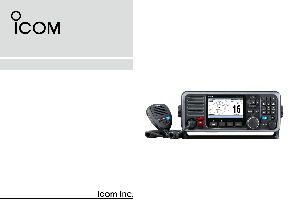
INSTRUCTION MANUAL
VHF MARINE TRANSCEIVERS
iM605
iM605EURO
Thank you for choosing this Icom product.
This product is designed and built with Icom’s state of the art
technology and craftsmanship.
With proper care, this product should provide you with years
of trouble-free operation.
The IC-M605/IC-M605EURO
DSC functions for distress alert transmission and reception,
as well as the general DSC calls (Individual calls, All Ships
calls, Group calls, and so on).
vhf marine transceiver has
EXPLICIT DEFINITIONS
WORD DEFINITION
RWARNING!
CAUTION
NOTE
Personal injury, re hazard or electric
shock may occur.
Equipment damage may occur.
If disregarded, inconvenience only. No risk
of personal injury, re or electric shock.
IMPORTANT
READ ALL INSTRUCTIONS carefully and completely
before using the transceiver.
SAVE THIS INSTRUCTION MANUAL — This instruction
manual contains important operating instructions for the
IC-M605/IC-M605EURO.
Icom is not responsible for the destruction, damage to, or
performance of any Icom or non-Icom equipment, if the
malfunction is because of:
• Force majeure, including, but not limited to, res,
earthquakes, storms, oods, lightning, other natural
disasters, disturbances, riots, war, or radioactive
contamination.
• The use of Icom transceivers with any equipment that is
ii
not manufactured or approved by Icom.
CLEAN THE FRONT PANEL THOROUGHLY WITH FRESH
WATER after exposure to saltwater, and dry it before
operating. Otherwise, the front panel’s keys, switches and
controllers may become unusable, due to salt crystallization.
NOTE: If the front panel’s waterproof protection appears
defective, carefully clean it with a soft, wet (fresh water)
cloth, then, dry it before operating.
The front panel may lose its waterproof protection if the
case or connector cover is cracked or broken, or the
transceiver has been dropped.
Icom, Icom Inc. and Icom logo are registered trademarks of Icom Incorporated
(Japan) in Japan, the United States, the United Kingdom, Germany, France,
Spain, Russia, Australia, New Zealand, and/or other countries.
AquaQuake is a trademark of Icom Incorporated.

IN CASE OF EMERGENCY
INSTALLATION NOTE
If your vessel requires assistance, contact other vessels and
the Coast Guard by sending a Distress call on Channel 16.
USING CHANNEL 16
DISTRESS CALL PROCEDURE
1. “MAYDAY MAYDAY MAYDAY.”
2. “THIS IS ...............” (name of vessel).
3. Say your call sign or other description of the vessel
(AND 9 digit DSC ID if you have one).
4. “LOCATED AT ...............” (your position).
5. State the nature of the distress and assistance required.
6. Give any other information which might facilitate the
rescue.
Or, transmit your Distress call using Digital Selective Calling
on Channel 70.
USING DIGITAL SELECTIVE CALLING (Ch 70)
DISTRESS CALL PROCEDURE
1. While lifting up the key cover, hold down [DISTRESS]
for 3 seconds until you hear 3 short beeps and then
one long beep.
2. Wait for an acknowledgment on Channel 70 from a
coast station.
• After the acknowledgement is received, Channel 16 is
automatically selected.
3. Hold down [PTT], then transmit the appropriate
information as listed above.
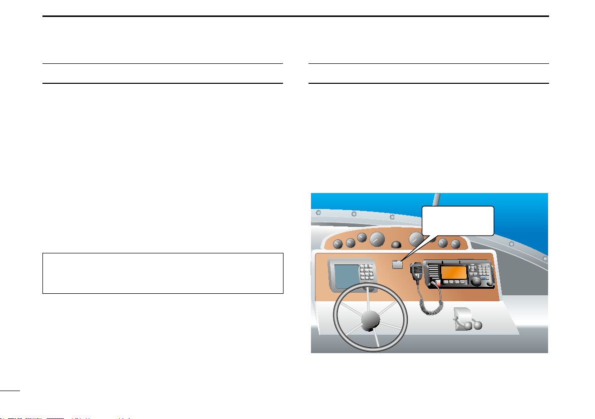
Installation:
The installation of this equipment should be made in such a
manner as to respect the EC recommended electromagnetic
eld exposure limits. (1999/519/EC)
The maximum RF power available from this device is 25
watts. The antenna should be installed as high as possible
for maximum efciency and the installation height should be
at least 1.76 meters above any accessible position. In the
case where an antenna cannot be installed at a reasonable
height, then the transmitter should neither be continuously
operated for long periods if any person is within a distance
of 1.76 meters of the antenna, nor operated at all if any
person is touching the antenna.
It is recommended that antenna of a maximum gain of
3 dB is used. If higher gain antenna are required then
please contact your Icom distributor for revised installation
recommendations.
Operation:
The exposure to RF electromagnetic eld is only applicable
when this device is transmitting. This exposure is naturally
reduced due to the nature of alternating periods of receiving
and transmitting. Keep your transmissions to the minimum
necessary.
ii

RADIO OPERATOR WARNING
Icom requires the radio operator to meet the FCC
Requirements for Radio Frequency Exposure. An
omnidirectional antenna with gain not greater than 9
WARNING
personnel. This is the minimum safe separation distance estimated
to meet all RF exposure compliance requirements. This 5 meter
distance is based on the FCC Safe Maximum Permissible Exposure
(MPE) distance of 3 meters added to the height of an adult (2
meters) and is appropriate for all vessels.
For watercraft without suitable structures, the antenna must be
mounted so as to maintain a minimum of 1 meter vertically between
the antenna, (measured from the lowest point of the antenna), to
the heads of all persons AND all persons must stay outside of the 3
meter MPE radius.
Do not transmit with radio and antenna when persons are within the
MPE radius of the antenna, unless such persons (such as driver
or radio operator) are shielded from antenna eld by a grounded
metallic barrier. The MPE Radius is the minimum distance from
the antenna axis that person should maintain in order to avoid RF
exposure higher than the allowable MPE level set by FCC.
dBi must be mounted a minimum of 5 meters
(measured from the lowest point of the antenna)
vertically above the main deck and all possible
FAILURE TO OBSERVE THESE LIMITS MAY ALLOW THOSE
WITHIN THE MPE RADIUS TO EXPERIENCE RF RADIATION
ABSORPTION WHICH EXCEEDS THE FCC MAXIMUM
PERMISSIBLE EXPOSURE (MPE) LIMIT.
IT IS THE RESPONSIBILITY OF THE RADIO OPERATOR TO
ENSURE THAT THE MAXIMUM PERMISSIBLE EXPOSURE
LIMITS ARE OBSERVED AT ALL TIMES DURING RADIO
TRANSMISSION. THE RADIO OPERATOR IS TO ENSURE
THAT NO BYSTANDERS COME WITHIN THE RADIUS OF THE
MAXIMUM PERMISSIBLE EXPOSURE LIMITS.
Determining MPE Radius
THE MAXIMUM PERMISSIBLE EXPOSURE (MPE) RADIUS HAS
BEEN ESTIMATED TO BE A RADIUS OF ABOUT 3M PER OET
BULLETIN 65 OF THE FCC.
THIS ESTIMATE IS MADE ASSUMING THE MAXIMUM POWER
OF THE RADIO AND ANTENNAS WITH A MAXIMUM GAIN OF
9dBi ARE USED FOR A SHIP MOUNTED SYSTEM.
iii

AVERTISSEMENT POUR LES OPÉRATEURS RADIO
AVERTISSEMENT
verticalement au-dessus du pont principal et de tout le personnel qui
peut s'y trouver. Il s'agit de la distance de sécurité minimale prévue
pour satisfaire aux exigences de conformité en matière d'exposition
aux RF. Cette distance de 5 mètres est établie en fonction de
l'exposition maximale admissible sécuritaire de 3 mètres établie par
la FCC, à laquelle on ajoute la hauteur d'un adulte (2 mètres); cette
distance convient pour tous les navires.
Dans le cas des embarcations sans structure convenable, l'antenne
doit être xée de façon à maintenir une distance minimale de 1 mètre
verticalement entre cette antenne (mesurée depuis son point le plus
bas) et la tête de toute personne présente; toutes les personnes
présentes doivent se tenir à l'extérieur d'un rayon d'exposition
maximale admissible de 3 mètres.
Ne pas émettre à l'aide de la radio et de l'antenne lorsque des
personnes se trouvent à l'intérieur du rayon d'exposition maximale
admissible de cette antenne, à moins que ces personnes (comme
le conducteur ou l'opérateur radio) ne soient protégées du champ
de l'antenne par un écran métallique relié à la masse. Le rayon
d'exposition maximale admissible équivaut à la distance minimale
que cette personne doit maintenir entre elle et l'axe de l'antenne
pour éviter une exposition aux RF supérieure au niveau d'exposition
maximale admissible xé par la FCC.
Icom exige que l'opérateur radio se conforme aux
exigences de la FCC en matière d'exposition aux
radiofréquences. Une antenne omnidirectionnelle
dont le gain ne dépasse pas 9dBi doit être
xée à une distance minimale de 5 mètres
(mesurée depuis le point le plus bas de l'antenne)
LE NON-RESPECT DE CES LIMITES PEUT CAUSER,
POUR LES PERSONNES SITUÉES DANS LE RAYON
D'EXPOSITION MAXIMALE ADMISSIBLE, UNE ABSORPTION
DE RAYONNEMENT DE RF SUPÉRIEURE À L'EXPOSITION
MAXIMALE ADMISSIBLE FIXÉE PAR LA FCC.
L'OPÉRATEUR RADIO EST RESPONSABLE D'ASSURER QUE
LES LIMITES D'EXPOSITION MAXIMALE ADMISSIBLE SOIENT
RESPECTÉES EN TOUT TEMPS PENDANT LA TRANSMISSION
RADIO. L'OPÉRATEUR RADIO DOIT S'ASSURER QU'AUCUNE
PERSONNE PRÉSENTE NE SE SITUE À L'INTÉRIEUR DU
RAYON D'EXPOSITION MAXIMALE ADMISSIBLE.
Établir le rayon d'exposition maximale admissible
ON ESTIME QUE LE RAYON D'EXPOSITION MAXIMALE
ADMISSIBLE EST D'ENVIRON 3 M, TEL QUE STIPULÉ DANS
LE BULLETIN OET 65 DE LA FCC. CETTE DISTANCE ESTIMÉE
TIENT COMPTE D'UN SYSTÈME INSTALLÉ SUR UN NAVIRE
UTILISANT LA PUISSANCE MAXIMALE DE LA RADIO ET DES
ANTENNES DONT LE GAIN MAXIMAL EST DE 9dBi.
iv
FCC INFORMATION
NOTE
• FOR CLASS A UNINTENTIONAL RADIATORS:
This equipment has been tested and found to comply with
the limits for a Class A digital device, pursuant to part 15
of the FCC Rules. These limits are designed to provide
reasonable protection against harmful interference when the
equipment is operated in a commercial environment. This
equipment generates, uses, and can radiate radio frequency
energy and, if not installed and used in accordance with the
instruction manual, may cause harmful interference to radio
communications.
Operation of this equipment in a residential area is likely to
cause harmful interference in which case the user will be
required to correct the interference at his own expense.
CAUTION: Changes or modications to this device, not
expressly approved by Icom Inc., could void your authority
to operate this device under FCC regulations.
A WARNING STICKER is supplied with the USA version
transceiver.
To comply with FCC regulations, this sticker must be afxed
in such a location as to be readily seen from the operating
controls of the radio as in the diagram below. Make sure the
chosen location is clean and dry before applying the sticker.
EXAMPLE
WARNING
STICKER
v

PRECAUTIONS
RWARNING! NEVER connect the transceiver to an AC outlet.
This may pose a re hazard or result in an electric shock.
RWARNING! NEVER connect the transceiver to a power
source of more than 16 V DC such as a 24 V battery. This
could damage the transceiver.
RWARNING! NEVER reverse the DC power cable polarity
when connecting to a power source. This could damage the
transceiver.
RWARNING! NEVER cut the DC power cable between the
DC plug at the back of the transceiver and the fuse holder. If
an incorrect connection is made after cutting, the transceiver
may be damaged.
RWARNING! NEVER operate the transceiver during a
lightning storm. It may result in an electric shock, cause a
re or damage the transceiver. Always disconnect the power
source and antenna before a storm.
RWARNING!
operation of the vessel may be hindered, or where it could
cause bodily injury.
CAUTION: KEEP the transceiver and microphone at least 1
meter away from the vessel’s magnetic navigation compass.
NEVER place the transceiver where normal
CAUTION: DO NOT place or leave the transceiver in areas
with temperatures below –20°C ~ +60°C (–4ºF ~ +140ºF), or
in areas subject to direct sunlight, such as a dashboard.
CAUTION: DO NOT use harsh solvents such as Benzine
or alcohol to clean the transceiver, as they will damage the
transceiver’s surfaces. If the transceiver becomes dusty or
dirty, wipe it clean with a soft, dry cloth.
BE CAREFUL! The transceiver rear panel will become hot
when transmitting continuously for long periods of time.
Place the transceiver in a secure place to avoid inadvertent
use by unauthorized persons.
BE CAREFUL! The transceiver’s front panel meets
IPX8 requirements and the optional HM-195/HM-229
commandmic meet IPX7 requirements for waterproof
protection*. However, once the transceiver or microphone
has been dropped, or the waterproof seal is cracked or
damaged, waterproof protection cannot be guaranteed
because of possible damage to the case or the waterproof
seal.
* Except for the DC power connector, NMEA In/Out leads and AF
Out leads.
vi

PRÉCAUTIONS
vii
RAVERTISSEMENT ! NE JAMAIS relier l'émetteur-récepteur à
une prise CA. Cela pourrait provoquer un choc électrique ou un
incendie.
RAVERTISSEMENT ! NE JAMAIS brancher l'émetteur-récepteur
sur une source d'alimentation supérieure à 16 V CC, comme une
batterie de 24 V. Cela pourrait endommager l'émetteur-récepteur.
RAVERTISSEMENT ! NE JAMAIS inverser la polarité du câble
d'alimentation CC lors de la connexion à une source d'alimentation.
Cela pourrait endommager l'émetteur-récepteur.
RAVERTISSEMENT ! NE JAMAIS couper le câble d'alimentation
CC entre la prise CC a l’arrière de l’émetteur-récepteur et le portefusible. L’émetteur-récepteur peut être endommagé par la suite en
cas de connexion inappropriée.
RAVERTISSEMENT ! NE JAMAIS utiliser l'émetteur-récepteur
durant un orage. Cela risquerait de provoquer un choc électrique,
un incendie ou d'endommager l'émetteur-récepteur. Toujours
débrancher la source d'alimentation et l'antenne avant une tempête.
MISE EN GARDE : NE JAMAIS installer l’émetteur-récepteur à
un emplacement où il pourrait gêner le fonctionnement normal du
navire ou provoquer des blessures corporelles.
INSTALLER la VHF et le microphone à au moins 1 m du compas
de route du navire.
NE PAS utiliser ou placer l’émetteur-récepteur dans des zones où
la temperature est inférieure à –15° ou supérieure à +55° ou dans
des zones soumises au rayonnement solaire direct, telles le tableau
de bord.
NE PAS nettoyer l'appareil avec des solvants agressifs tels que
benzène ou alcool, susceptibles d'endommager les surfaces
exposées du boitier. En cas de dépôt de poussière ou de salissures
sur l'émetteur-récepteur, il faut l'essuyer avec chiffon doux et sec.
MISE EN GARDE ! La face arrière de la VHF chauffe en cas
d’utilisation continue sur une longue durée.
Placer l’émetteur-récepteur hors de portée des enfants pour éviter
toute utilisation inopinée.
MISE EN GARDE ! La face avant de l'émetteur-récepteur est
étanche conformément à la norme IPX7*. L’étanchéité ne peut plus
être garantie après une chute de l’appareil en raison des risques de
ssures du boîtier, de dégradation du joint d’étanchéité, etc.
*Les connecteurs sur le panneau arrière ne sont pas étanche IPX7.
Si la face avant est exposée à de l'eau de mer, ASSUREZ-VOUS
DE LE NETTOYER ENTIEREMENT AVEC DE L'EAU DOUCE
lorsque la protection étanche sur le panneau avant fonctionne.
Dans le cas contraire, les touches et le commutateur risquent de ne
plus fonctionner en raison de la cristallisation du sel.
Icom ne peut pas être tenu pour responsable de la destruction, de la
détérioration ou des performances d'un équipement Icom ou non-Icom,
si le dysfonctionnement survient à cause de :
• Force majeure, sans toutefois s'y limiter, les incendies, tremblements de
terre, tempêtes, inondations, la foudre, d'autres catastrophes naturelles,
perturbations, émeutes, guerre, ou contamination radioactive.
• L'utilisation d'un émetteur-récepteur Icom avec tout équipement non
fabriqué ou approuvé par Icom.
ACTION ICON DESCRIPTION
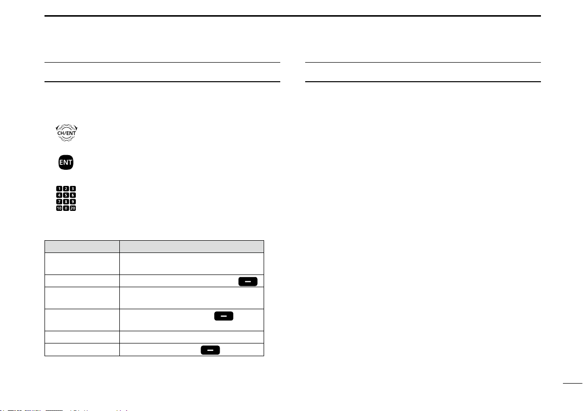
TABLE OF CONTENTS
The following describes the [CH/ENT], [ENT] and the
keypad operations in this instruction manual.
Rotate
: Rotate [CH/ENT] to select.
Push
: Push [ENT] to enter or set.
Push
: Push the keypad to enter
a digit or text.
Also, you can use the following key functions in the Menu
screen.
FUNCTION ACTION
Select Rotate [CH/ENT].
Push [∫] or [√].
Enter Push [ENT], [CH/ENT], or [Enter]
Go to the next tree
level
Go back to the
previous tree level
Cancel Push [CLR].
Exit Push [MENU] or [Exit]
Push [ENT] or [≈].
Push [CLR], [Ω], or [Back]
.
.
.
IMPORTANT ...................................................................................... i
EXPLICIT DEFINITIONS ................................................................... i
IN CASE OF EMERGENCY ............................................................. ii
INSTALLATION NOTE ..................................................................... ii
RADIO OPERATOR WARNING .......................................................iii
AVERTISSEMENT POUR LES OPÉRATEURS RADIO ................. iv
FCC INFORMATION ........................................................................v
NOTE ................................................................................................ v
PRECAUTIONS ............................................................................... vi
PRÉCAUTIONS ...............................................................................vii
ACTION ICON DESCRIPTION ......................................................viii
1 OPERATING RULES ..................................................................1
2 PANEL DESCRIPTION ........................................................... 2–8
Front panel .............................................................................. 2
■
Software Key function ............................................................. 5
■
Speaker Microphone ............................................................... 6
■
Function display (Main screen) ............................................... 6
■
3 PREPARATION .....................................................................9–10
Entering the MMSI code .........................................................9
■
Entering the ATIS code (For Dutch and German versions) ...10
■
4 MENU SCREEN .................................................................. 11–13
Construction .......................................................................... 11
■
Selecting a Menu item ..........................................................13
■
5 BASIC OPERATION ...........................................................14–21
Selecting a channel ...............................................................14
■
Setting the Call channel ........................................................ 17
■
Microphone Lock function .....................................................17
■
Receiving and transmitting ....................................................18
■
Backlight function .................................................................. 19
■
Entering a Channel name ..................................................... 20
■
Using the AquaQuake water draining function ......................21
■
viii

TABLE OF CONTENTS (Continued)
6 SCAN OPERATION (Except for the Dutch version) ........22–23
Scan types ............................................................................ 22
■
Favorite channels ..................................................................23
■
Starting a scan ...................................................................... 23
■
7 DUALWATCH/TRI-WATCH (Except for the Dutch version) ..24
Description ............................................................................ 24
■
Operation .............................................................................. 24
■
8 DSC OPERATION ...............................................................25–64
DSC address ID .................................................................... 25
■
Entering the position and time ..............................................27
■
DSC Task mode (Single) .......................................................29
■
DSC Task mode (Multiple) ....................................................30
■
Sending a Distress call .........................................................31
■
Sending a Non-Distress call ..................................................37
■
Receiving DSC calls .............................................................45
■
Received Call log .................................................................. 56
■
Transmitted Call log ..............................................................57
■
DSC Settings ........................................................................58
■
Making an Individual call using an AIS transponder .............63
■
9 OTHER FUNCTIONS .......................................................... 65–70
Using the Intercom ................................................................ 65
■
Using the RX Hailer ..............................................................66
■
Using the Hailer ....................................................................66
■
Using the Horn ...................................................................... 67
■
Using the Voice Scrambler ...................................................69
■
Using the Voice Recorder .....................................................70
■
10 AIS RECEIVER ................................................................... 71–81
About AIS .............................................................................. 71
■
AIS Classes ..........................................................................71
■
Function display .................................................................... 72
■
About the detail screen ......................................................... 74
■
AIS Settings .......................................................................... 78
■
11 MENU ITEMS ...................................................................... 82–91
Menu items ...........................................................................82
■
GPS Information ...................................................................83
■
Conguration .........................................................................83
■
Radio Settings .......................................................................86
■
NMEA Settings ......................................................................89
■
Radio Information ..................................................................91
■
12 CONNECTIONS AND MAINTENANCE .............................. 92–99
Connections .......................................................................... 92
■
Antenna .................................................................................94
■
Fuse replacement ................................................................. 94
■
Cleaning ................................................................................ 94
■
Supplied accessories ............................................................ 95
■
Mounting the transceiver .......................................................96
■
MB-75 installation .................................................................97
■
Microphone installation ......................................................... 98
■
13 SPECIFICATIONS AND OPTIONS .................................100–103
Specications ...................................................................... 100
■
Options ................................................................................102
■
14 TROUBLESHOOTING .................................................... 104–105
15 CHANNEL LIST ...................................................................... 106
16 INFORMATION .......................................................................107
Country code list ................................................................. 107
■
Disposal .............................................................................. 107
■
INDEX...................................................................................108–110
ix

OPERATING RULES
1
D Priorities
• Read all rules and regulations pertaining to call priorities,
and keep an up-to-date copy handy. Safety and distress
calls take priority over all others.
• You must monitor Channel 16 when you are not operating
on another channel.
• False or fraudulent distress calls are prohibited under law.
D Privacy
• Information overheard, but not intended for you, cannot
lawfully be used in any way.
• Indecent or profane language is prohibited.
D Radio licenses
(1) SHIP STATION LICENSE
You may require a current radio station license before using
the transceiver. It is unlawful to operate a ship station which
is not licensed, but required to be.
If required, contact your dealer or the appropriate
government agency for a Ship-Radiotelephone license
application. This government-issued license states the call
sign which is your craft’s identication for radio purposes.
(2) OPERATOR’S LICENSE
A Restricted Radiotelephone Operator Permit is the license
most often held by small vessel radio operators when a
radio is not required for safety purposes.
If required, the Restricted Radiotelephone Operator Permit
must be posted or kept with the operator. If required, only a
licensed radio operator may operate a transceiver.
However, non-licensed individuals may talk over a
transceiver if a licensed operator starts, supervises, ends
the call and makes the necessary log entries.
A current copy of the applicable government rules and
regulations is only required to be on hand for vessels in
which a radio telephone is compulsory. However, even
if you are not required to have these on hand it is your
responsibility to be thoroughly acquainted with all pertinent
rules and regulations.
NOTE: Even though the transceiver is capable of operation
on VHF marine channels 3, 21, 23, 61, 64, 81, 82 and
83, according to FCC regulations these simplex channels
cannot be lawfully used by the general population in USA
waters.
1
2
3
4
5
6
7
8
9
10
11
12
13
14
15
16
1

2
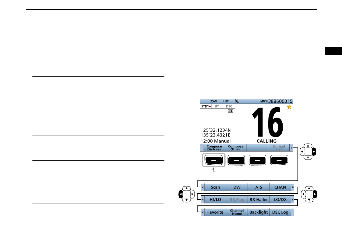
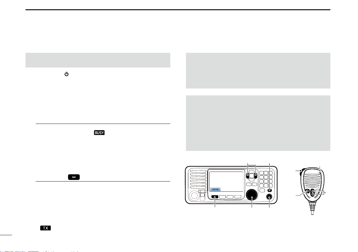
PANEL DESCRIPTION
■ Front panel
q DISTRESS KEY [DISTRESS]
Speaker Function display
MIC CONNECTOR
!2
SOFTWARE KEYS
w ENTER KEY [ENT]
e LEFT AND RIGHT KEYS [Ω]/[≈]
UP AND DOWN KEYS [∫]/[√]
r
o CLEAR KEY [CLR]
!0 CHANNEL SELECTOR/ENTER SWITCH [CH/ENT]
!1 MENU KEY [MENU]
t KEYPAD
y POWER KEY [
u CHANNEL 16/
CALL CHANNEL KEY [16/C]
i VOLUME/SQUELCH DIAL [VOL/SQL]
]
2

PANEL DESCRIPTION
2
q DISTRESS KEY [DISTRESS] (p. 31)
Hold down for 3 seconds to transmit a Distress call.
w ENTER KEY [ENT]
Push to set the entered data, selected item, and so on.
e LEFT AND RIGHT KEYS [◄]/[►]
z Push to scroll the Software Key functions. (p. 5)
z In the character or number entry mode, push to select
a character or number in the keypad. (p. 20)
r
UP AND DOWN/CHANNEL SELECT KEYS [▲]/[▼]
z Push to select an operating channel, (p. 14), Menu
items, Menu settings, (p. 13) and so on.
z While scanning, push to check the Favorite channels,
change the scanning direction or manually resume a
scan. (p. 23)
t KEYPAD
Push to enter numbers, letters or symbols.
For channel number entry, see page 14.
For channel name entry, see page 20
y POWER KEY [
Hold down for 1 second to turn the transceiver ON or
OFF.
]
u CHANNEL 16/CALL CHANNEL KEY [16/C]
z Push to select Channel 16. (p. 14)
z
Hold down for 1 second to select the Call channel.
(p. 14)
• “CALL” is displayed when the Call channel is selected.
i VOLUME/SQUELCH DIAL [VOL/SQL] (p. 18)
z Rotate to adjust the volume level.
z Push once or twice to display the Volume or Squelch
Setting screen, and then rotate to adjust the volume or
squelch level.
o CLEAR KEY [CLR]
Push to cancel the entered data, or to return to the
previous screen.
!0 CHANNEL SELECTOR/ENTER SWITCH [CH/ENT]
z Rotate to select an operating channel (p. 14), Menu
items or Menu settings (p. 13).
z Push to set the entered data, or selected item.
!1 MENU KEY [MENU]
Push to enter or exit the Menu screen.
(p. 13)
1
2
3
4
6
7
8
9
10
11
12
13
14
15
16
3

2
PANEL DESCRIPTION
■ Front panel (Continued)
!2 SOFTWARE KEYS (p. 5)
You can use various key functions that are assigned to
the Software Keys, as described below.
Compose Distress (p. 31)
Push to display the COMPOSE DISTRESS screen.
Compose Other (p. 37)
Push to display the COMPOSE NON-DISTRESS screen.
Unread List
When the transceiver has unread DSC calls, push to
enter the Unread List.
L Displayed only when “Single” is selected in the DSC
procedure menu. (p. 62)
Dualwatch/Tri-watch [DW/TW] (p. 24)
(Except for the Dutch version.)
Push to start or stop the Dualwatch or Tri-watch.
AIS (p. 72)
Push to display the AIS plotter on the left side of the
display.
L An AIS receiver may not be installed, depending on the
transceiver version.
Channel/ Weather [CH/WX] (p. 16)
(For only the USA version.)
Push to select either the regular channels or the Weather
channels.
Task List (p. 30)
(For only the USA version.)
When the transceiver has any task, push to enter the
Task List.
L Displayed only when “Multiple” is selected in the DSC
procedure menu. (p. 62)
Scan (p. 22)
(Except for the Dutch version.)
Push to start or stop a Normal or Priority scan.
4
Channel [CHAN] (p. 14)
(For only the versions except the USA version. )
Push to enter the regular channel selection mode.
High/Low [HI/LO] (p. 18)
Push to set the output power level to high or low.
L Some channels are set to only low power.
Voice Scrambler (p. 69)
Push to set the Voice Scrambler function.
L This function is displayed only when the voice scrambler unit
is installed.
PANEL DESCRIPTION
2
RX Play (p. 70)
Push to play recorded audio.
RX Hailer (p. 66)
Push to turn the RX Hailer mode ON or OFF.
LO/DX
(For only the USA version.)
Push to turn the Attenuator function ON or OFF.
L The “LOCAL” icon is displayed when the Attenuator function
is ON.
Favorite channel [Favorite]
Push to set or clear the displayed channel as a Favorite
channel. (p. 14)
Channel Name (p. 20)
Push to display the CHANNEL NAME screen.
Backlight (p. 5)
Push to open the Backlight Settings window.
DSC Log (p. 56)
Push to display the RECEIVED CALL LOG screen.
■ Software Key function
The transceiver has Software Keys for various functions.
The key function is displayed above the Software Key.
D Selecting the Software Key function
When “Ω” or “≈” is displayed beside the key icon, pushing
[Ω] or [≈] scrolls the Software Key functions.
When you push [Ω] or [≈] once, 4 functions scroll together.
Push
Push this key to display the
COMPOSE DISTRESS screen.
PushPush
1
2
3
4
5
6
7
8
9
10
11
12
13
14
15
16
* The key functions may differ, depending on the transceiver version.
5
2
PANEL DESCRIPTION
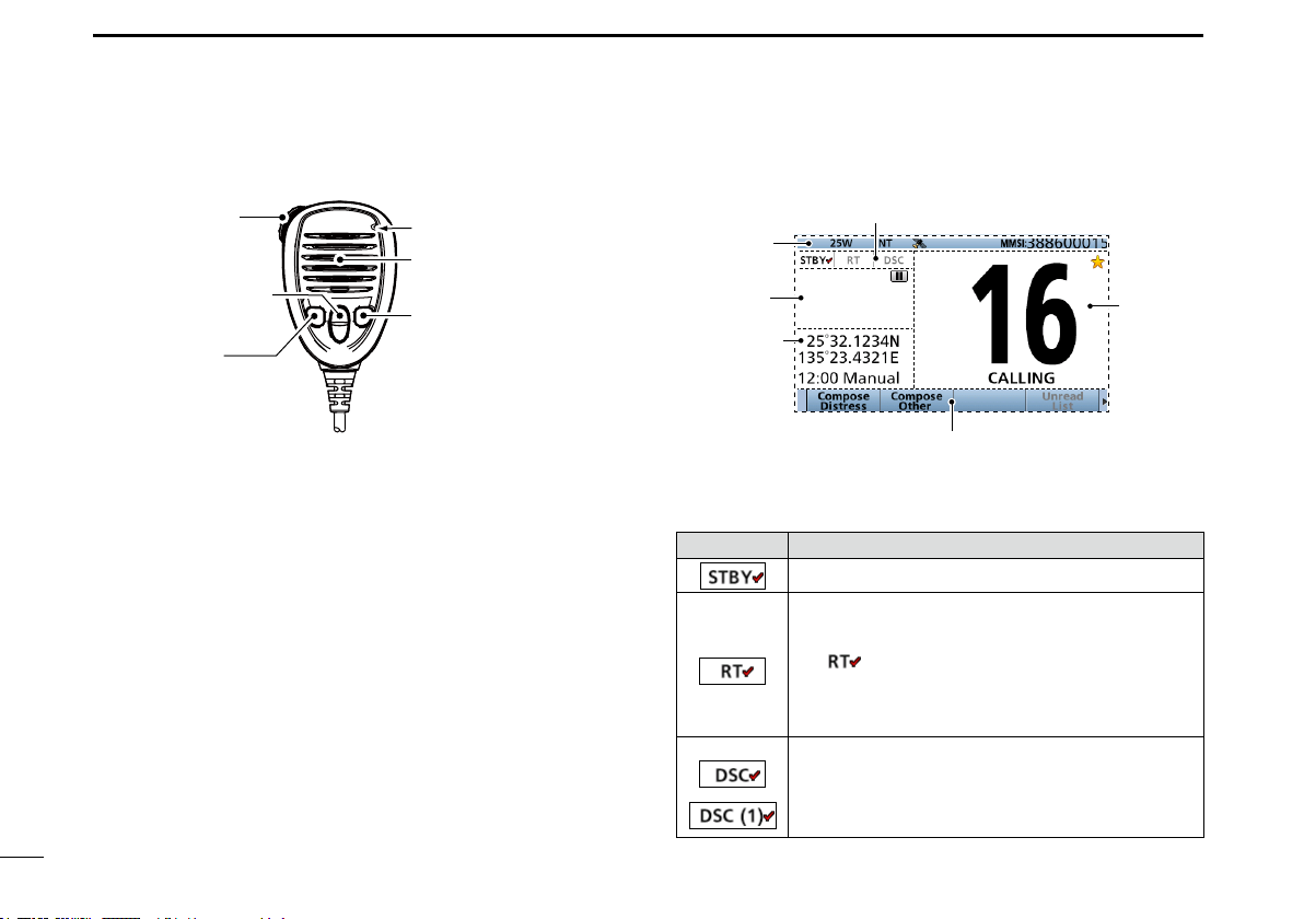
■ Speaker Microphone
q PTT SWITCH
[PTT]
w UP/DOWN KEYS
[Y]/[Z]
e TRANSMIT
POWER KEY
[H/L]
q PTT SWITCH [PTT] (p. 18)
Hold down to transmit, release to receive.
w UP/DOWN KEYS [▲]/[▼] (p. 18)
Push to select the Favorite channels, change scanning
direction or manually resume a scan.
L When the “FAV on MIC” item is set to “OFF,” you can select
all channels. (p. 18)
e TRANSMIT POWER KEY [H/L]
z Push to set the power level to high or low.
L Some channels are set to only low power.
z While holding down this key, turn ON the transceiver to
turn the Microphone Lock function ON or OFF. (p. 17)
r CHANNEL 16/CALL CHANNEL KEY [16/C] (p. 14)
z Push to select Channel 16.
z Hold down for 1 second to select the Call channel.
• The “CALL” icon is displayed.
6
Microphone
Speaker
r CHANNEL 16/
CALL CHANNEL KEY
[16/C]
■ Function display (Main screen)
Mode/Task area
Information
area
Status area
Position and
Time area
Software Key area
D Mode/Task area
The current mode is displayed in the Mode and Task area.
Indicator Description
Displayed while in the Standby mode.
Displayed while in the Radio Telephone (RT)
mode.
L “ ” is displayed when the RT mode task is
activated.
L Returns to the Standby mode if no operation
occurs during the preset period of time. (p. 6)
Displayed after making or receiving a DSC
call.
L If the transceiver is in the Multiple Task mode, the
number of DSC tasks is displayed by the indicator.
Channel
area
PANEL DESCRIPTION
2
D Channel area
The selected operating channel number, channel name, and
the following indicators are displayed in the Channel area.
Indicator Description
Displayed when a Favorite channel is selected.
CALL Displayed when the Call channel is selected
by holding down [16/C] for 1 second.
DUP Displayed when a Duplex channel is selected.
Displayed when the battery voltage is low.
D Position and Time area
POSITION AREA
The current position is displayed when valid GPS data is
received, or you manually enter your position.
Indicator Description
NO
POSITION
??
Displayed when a GPS antenna is not
connected or your position has not been
manually entered.
Blinks every 2 seconds instead of your
position when the GPS position is invalid.
L The last position is held for only 23.5 hours. After
that, “NO POSITION” will be displayed.
Blinks every 2 seconds instead of the position
after 4 hours have passed since you manually
entered your position.
L The manually entered position is held for only 23.5
hours. After that, “NO POSITION” will be displayed.
TIME AREA
The current time is displayed when valid GPS data is
received, or manually enter the time.
The date information is displayed when the RMC GPS
sentence formats are included in the GPS signal.
Indicator Description
Displayed when a GPS antenna is not
NO TIME
Local Displayed when the offset time is set.
Manual
UTC
??
connected or the time has not been manually
entered.
Displayed when the time was manually entered.
Displayed when the GGA, GLL or GNS
sentences are received from NMEA 0183.
Blinks every 2 seconds instead of the time
when the GPS current time is invalid.
L After 23.5 hours has passed, “NO TIME” will be
displayed.
Blinks every 2 seconds instead of the
time after 4 hours have passed since you
manually entered the time.
L The manually entered time is held for only 23.5
hours. After that, “NO TIME” will be displayed.
1
2
3
4
5
6
7
8
9
10
11
12
13
14
15
16
7
2
PANEL DESCRIPTION
■ Function display (Main screen) (Continued)
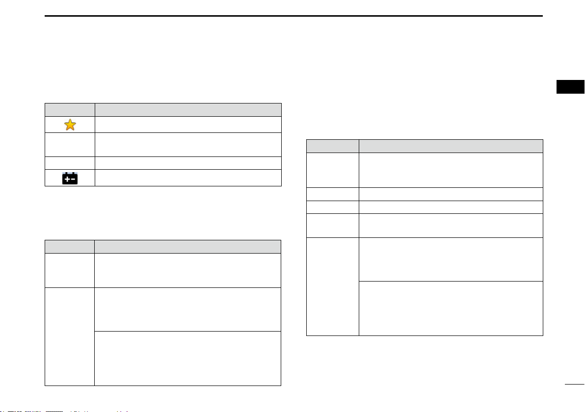
D Status area
The current status is displayed in the Status area.
Indicator Description
SCAN 16 Displayed during a Priority scan. (p. 23)*
SCAN Displayed during a Normal scan. (p. 23)*
DUAL 16 Displayed during Dualwatch. (p. 24)*
TRI 16 Displayed during Tri-watch. (p. 24)*
LOCAL Displayed when the Attenuator function is
turned ON.
*For only the USA version.
Displayed when in the RX Hailer mode.
(p. 66)
*Not usable in Dutch version.
• Displayed when recorded audio is played or
stopped. (p. 70)
• Displayed when received audio is recorded.
(p. 70)
D Information area
The MMSI code* and the following indicators are displayed
in the Information area.
* ATIS code is displayed if only the ATIS code is entered in Dutch
and German version.
Indicator Description
Displayed when receiving a signal or when the
squelch is open.
Displayed while transmitting.
25W Displayed when high power is selected.
1W Displayed when low power is selected.
USA, INT,
CAN, WX,
ATIS, DSC
• Displays the selected channel group. (p. 15)
• “WX” is displayed when the weather channel
is selected.
Displayed when the transceiver receives valid
position and time data.
Blinks when invalid GPS data is being received.
• Displayed when there are unread DSC
messages.
• Blinks when a DSC message is received.
Displayed when the “CH Auto Switch” in DSC
Settings is set to an option except “Accept.”
Displayed when the external speaker is
selected. (p. 85)
Displayed when the Auto Foghorn function is
activated. (p. 67)
8
PREPARATION
3
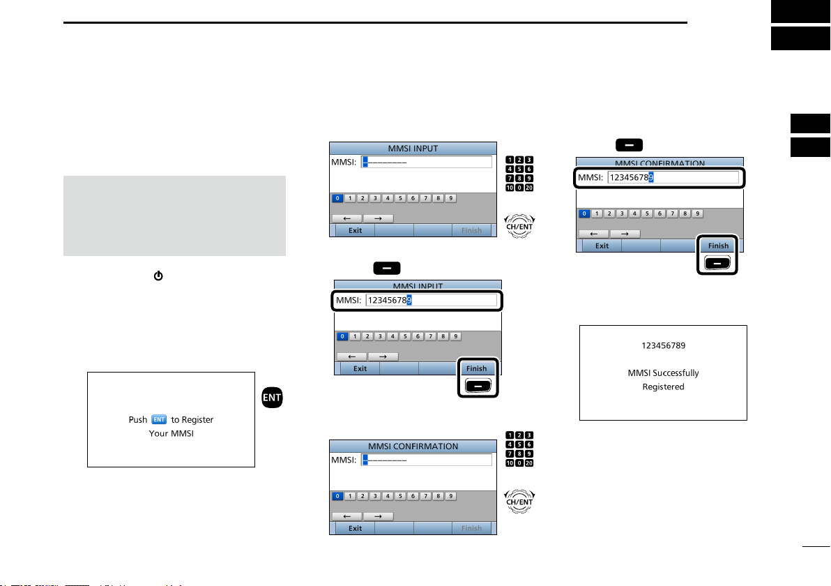
■ Entering the MMSI code
First, you must enter the 9 digit MMSI
(Maritime Mobile Service Identity: DSC
self ID) code at power ON.
NOTE: You can enter this initial code
ONLY ONCE. After entry, only your
dealer or distributor can change it.
If your MMSI code has already been
entered, this entry is not necessary.
1. Hold down [
ON the transceiver.
• Three short beeps sound.
• “Push [ENT] to Register Your MMSI” is
displayed.
2. Push [ENT] to enter the MMSI
code entry mode.
• Push [CLR] to cancel the entry. In that
case, the transceiver displays “Push
[ENT] to Register Your MMSI” again.
] for 1 second to turn
Push
3. Enter your 9 digit MMSI code.
4. After entering the 9th digit, push
[Finish]
5. Reenter your MMSI code to
confirm.
to set the ID.
Push
Push
+
Rotate
Push
+
Rotate
6. After entering the 9th digit, push
[Finish]
• When you successfully enter your
MMSI code, the following screen is
displayed.
• After that, the Main screen is
displayed. The registered MMSI code
is displayed at the top of the screen.
to register the ID.
Push
1
2
3
4
5
6
7
8
9
10
11
12
13
14
15
16
9
3
PREPARATION
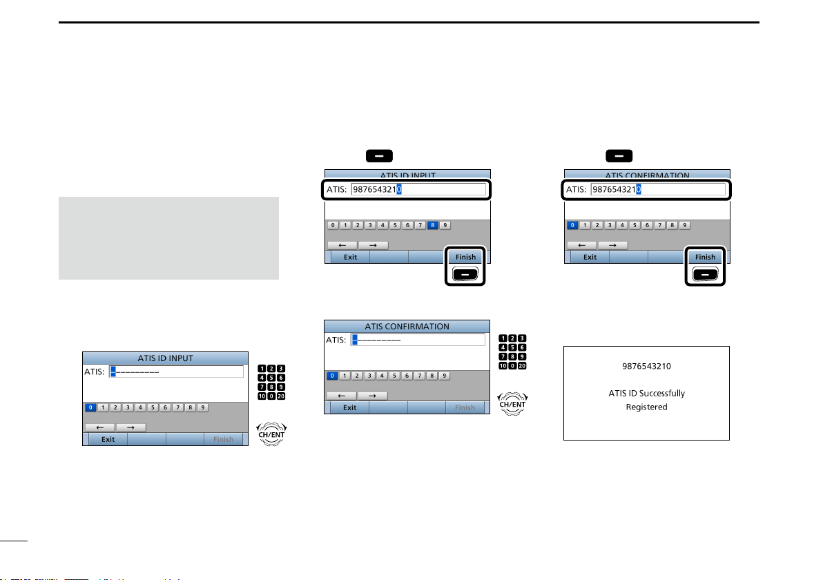
■ Entering the ATIS code (For Dutch and German versions)
The Automatic Transmitter Identication
System (ATIS) ID consists of 10 digits.
You can enter the ID in the “ATIS ID
Input” item on the Menu screen.
You can enter this ID ONLY ONCE.
After entry, only your dealer or
distributor can change it.
If your ATIS ID has already been
entered, this entry is not necessary.
1. Push [MENU].
2. Select “ATIS ID Input,” then push
[ENT].
3. Enter a 10 digit ATIS code.
Push
+
Rotate
4. After entering the 10th digit, push
[Finish]
5. Reenter your ATIS code to confirm.
to set the ID.
Push
Push
Rotate
6. After entering the 10th digit, push
[Finish]
• When you successfully enter your
ATIS code, the following screen is
displayed.
+
to register the ID.
Push
10
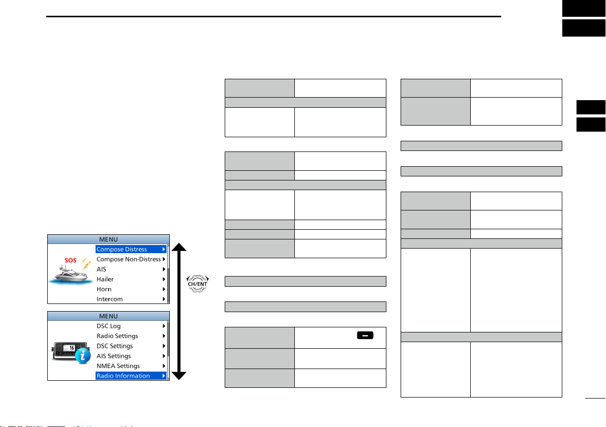
MENU SCREEN
4
You can use the Menu screen to
set infrequently changed values or
function settings.
■ Construction
The Menu screen is constructed in a
tree structure.
You can go to the next tree level with
[ENT], or go back a level with [CLR].
L See page viii for details.
To select an item, rotate [CH/ENT].
Rotate
1
May not be displayed, depending on the message type.
*
*2 Displayed when the optional command microphone or command head is connected to the transceiver.
• Compose Distress (p. 31)
Nature of Distress
Position
• Latitude
• Longitude
• UTC
• Compose Non-Distress (p. 37)
Message Type
Address*
Position*
• Latitude*
• Longitude*
• UTC*
Category
Mode*
Channel*
• AIS (p. 72)
Displays the AIS plotter.
• Hailer (p. 69)
Displays the Hailer function screen.
• Horn (p. 70)
Manual Horn
Auto Foghorn
Frequency
1
1
1
1
1
1
Select a Nature of
Distress option.
Displays latitude data.
Displays longitude data.
Displays UTC offset data.
Select a Message Type
option.
Enter a destination address.
Displays latitude data.
1
Displays longitude data.
Displays UTC offset data.
Select a Category option.
Displays a Mode.
Select an Intership
channel.
Hold down [Horn] to
sound a horn.
Select the automatic
foghorn pattern.
Select the foghorn’s audio
frequency.
• Intercom*2 (p. 66)
RADIO
SUB UNIT 1, 2, 3
• GPS Information (p. 83)
Displays the GPS information.
• AquaQuake (p. 21)
Displays the AquaQuake function screen.
• Conguration
Key Beep
Key Assignment
UTC Offset
Inactivity Timer
• Not DSC Related
• DSC Related
• Distress Related
• RT Related
Speaker
• Internal
• External
Displays the transceiver’s
name.
Displays name of the unit
that are connected for the
Intercom function.
Turn the Key Beep
function ON or OFF.
Select the items to the
assignable keys.
Set the UTC Offset.
Set the inactivity timer for
not DSC related calls.
Set the inactivity timer for
DSC related calls.
Set the inactivity timer for
Distress related calls.
Set the inactivity timer
for the Radio Telephone
mode.
The internal speaker
is ON and the external
speaker is OFF.
The internal speaker is
OFF and the external
speaker is ON.
1
2
3
4
5
6
7
8
9
10
11
12
13
14
15
16
11
4
MENU SCREEN
12
■ Construction (Continued)
Noise Cancel
• RX
• TX
Power SW from Sub Unit
• All Units
• Own Unit
Set the reduction level of
the Noise Cancel function.
Turn the Noise Cancel
function for the transmit
signal ON or OFF.
When you turn OFF the
command head, the
transceiver is turned OFF
at the same time.
The transceiver is not
turned OFF even if you
turned OFF the command
microphone.
WX Alert*
Voice Scrambler*
Voice Record
FAV Settings
FAV on MIC
• DSC Settings (p. 58)
Position Input*
Individual ID
Group ID
Auto ACK
• DSC Log (p. 56)
Received Call Log
Transmitted Call
Log
Displays the received
call log.
Displays the transmitted
call log.
CH Auto Switch
• Radio Settings (p. 86)
4
Scan Type*
Scan Timer*
Dual/Tri-Watch*
Channel Group
Call Channel
*1 May not be displayed, depending on the version.
*2 Not displayed, when valid GPS data is received.
*3 Displayed only when the voice scrambler unit is installed.
Select a Scan Type from
Normal Scan or Priority
Scan.
4
Turn the Scan Timer
function ON or OFF.
4
Select the Dualwatch or
Tri-watch function.
Select a channel group.
Set the Call channel.
DSC Data Output
Alarm Status
• Safety
• Routine
• Warning
1
*4 Not usable in Dutch version.
Turn the Weather Alert
function ON or OFF.
3
Set the Voice Scrambler
code.
Select whether or not to
automatically record the
voice audio.
Set the Favorite channel
settings.
Turn the FAV on MIC
function ON or OFF.
2
Enter your position.
Enter an Individual ID.
Enter a Group ID.
Select whether or not to
automatically transmit an
Acknowledgement after
receiving each type of call.
Select whether or to
automatically select the
channel that the DSC
call is received on, when
received.
Select a DSC Data Output
option.
Turn the Alarm Status for
Safety ON or OFF.
Turn the Alarm Status for
Routine ON or OFF.
Turn the Alarm Status for
Warning ON or OFF.
• Self-Terminate
• Discrete
CH 70 SQL Level
Self Check Test
Procedure*
Turn the Alarm Status for
Self-Terminate ON or OFF.
Turn the Alarm Status for
Discrete ON or OFF.
Select the Channel 70
squelch level.
Starts the self check Test.
1
Select the Single task
mode or Multiple task
mode.
• AIS Settings (p. 78)
North Up/COG Up
CPA/TCPA
ID Blocking
Select the display type
for AIS plotter.
Edit the alarm settings for
AIS receiver.
Enter the vessel’s or your
transponder ID to block.
• NMEA Settings (p. 89)
NMEA0183
• Port 1, Port 2
Select the data transfer
speed to receive and
transmit data from
external devices.
NMEA2000
• GPS, AIS
Select the sensors in
NMEA 2000 network
which sends GPS or AIS
data to the transceiver.
• Radio Information (p. 91)
Displays your transceiver’ s Serial number,
software version, GPS module version, and
so on.
MENU SCREEN
4
■ Selecting a Menu item
Follow the procedures described below
to select a Menu item.
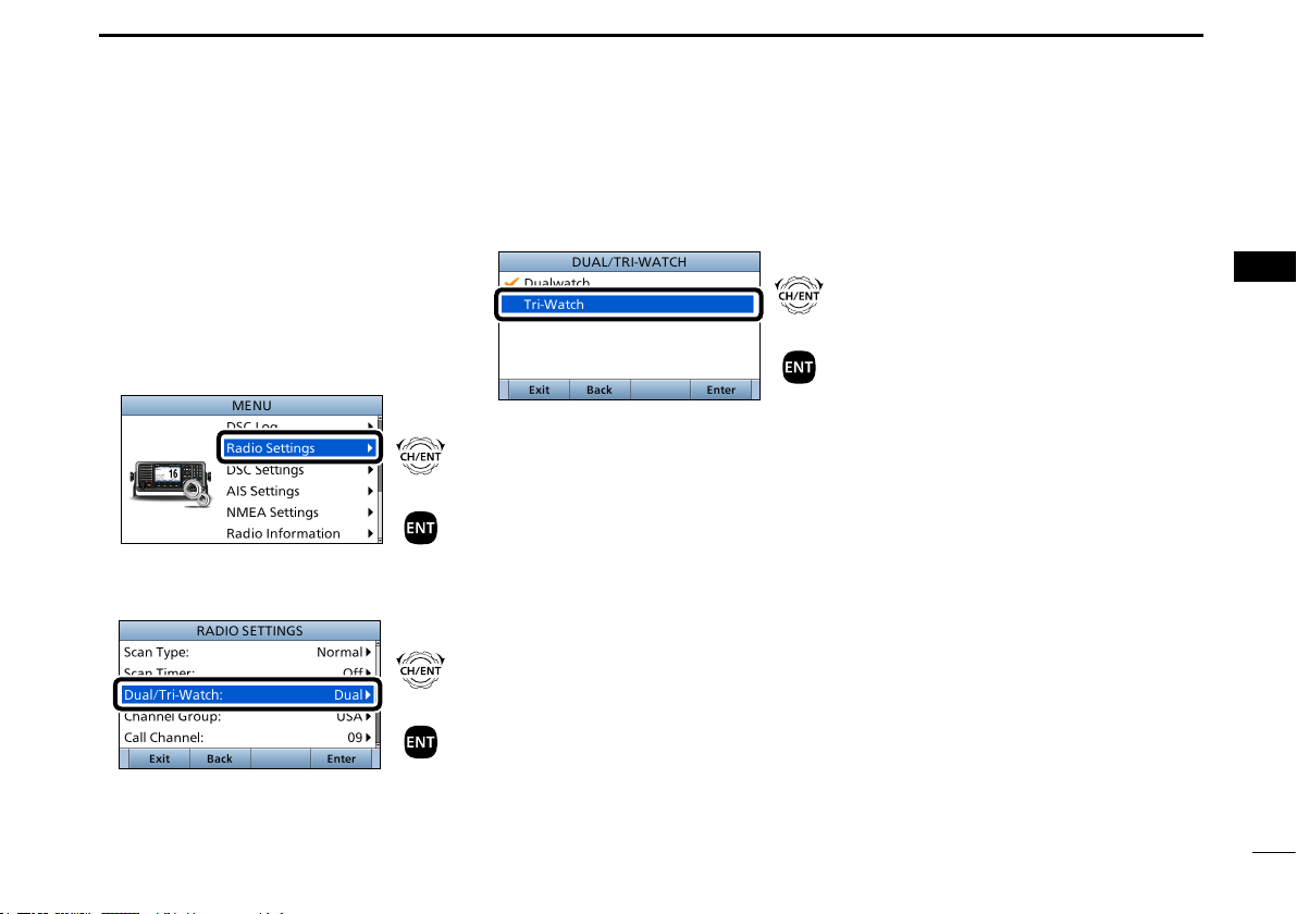
Example: Set the Tri-watch function.
1. Push [MENU] to display the MENU
screen.
2. Rotate [CH/ENT] to select
“Radio Settings,” then push [ENT].
Rotate
+
Push
3. Rotate [CH/ENT] to select
“Dual/Tri-Watch,” then push [ENT].
Rotate
+
Push
4. Rotate [CH/ENT] to select
“Tri-Watch,” and then push [ENT].
Rotate
+
Push
• Sets the Tri-watch function, and then
goes back to the RADIO SETTINGS
screen, after pushing [ENT].
5. Push [MENU] to return to the Main
screen.
1
2
3
4
5
6
7
8
9
10
11
12
13
14
15
16
13

5
BASIC OPERATION
■ Selecting a channel
D Selecting a regular channel
z Rotate [CH/ENT].
z Push [∫] or [√].
z Push the keypad to directly enter the channel number.
(Example: Selecting Channel 22)
Push [2
abc] → [2 abc].
Push
twice
D Selecting Channel 16
Channel 16 is the distress and safety channel. It is used for
establishing initial contact with a station, and for emergency
communications.
While standing by, you must monitor Channel 16.
z Push [16/C].
D Selecting Call channel
You have a leisure use Call channel for quick recall.
To set your most used channel, see page 17.
The default Call channel differs, depending on the
transceiver version.
z Hold down [16/C] for 1 second.
14
Displayed
BASIC OPERATION
5
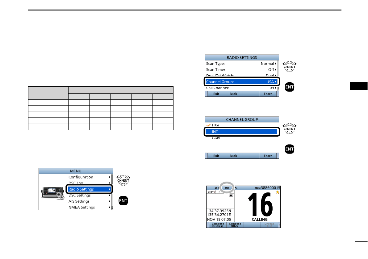
D Selecting a channel group
Channel Groups are preset into your transceiver. You can
select the Channel Group between USA, International,
Canadian, DSC, and ATIS, depending on the transceiver
version.
Version
USA
UK
European
Dutch
German
1. Push [MENU].
• The “MENU” screen is displayed.
2. Rotate [CH/ENT] to select “Radio Settings,” then push
[ENT].
USA INT CAN DSC ATIS
Preset Channel Group
Rotate
+
Push
3. Rotate [CH/ENT] to select “Channel Group,” then push
[ENT].
4. Rotate [CH/ENT] to select the Channel Group, then
push [ENT].
5. Push [MENU] to return to the Main screen.
• The selected Channel Group’s icon is displayed on the Main
screen.
Rotate
+
Push
Rotate
+
Push
1
2
3
4
5
6
7
8
9
10
11
12
13
14
15
16
15
5
BASIC OPERATION
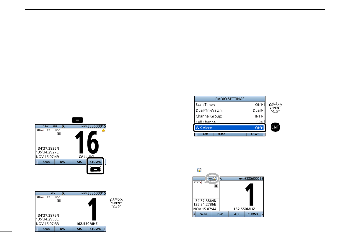
D Weather channels and Weather Alert function
For the USA version, the transceiver has 10 preset
Weather channels. You can use these channels to
monitor broadcasts from the National Oceanographic
and Atmospheric Administration (NOAA). The transceiver
automatically detects a Weather alert tone on the selected
weather channel, or while scanning.
Selecting a Weather channel
1. Push [Ω] or [≈] until “CH/WX” is displayed in the
Software Key area.
2. Push [CH/WX]
• “WX” is displayed instead of the Channel Group icon.
3. Rotate [CH/ENT] to select a Weather channel.
.
Push
Rotate
Setting the Weather Alert function
1. Push [MENU].
• The “MENU” screen is displayed.
2. Rotate [CH/ENT] to select “Radio Settings,” then push
[ENT].
3. Rotate [CH/ENT] to select “WX Alert,” then push [ENT].
• The “WX ALERT” screen is displayed.
4. Rotate [CH/ENT] to select “On with Scan” or “On,” then
push [ENT].
5. Push [MENU] to return to the Main screen.
• “ ” is displayed next to “WX” on the Main screen.
Rotate
+
Push
16
BASIC OPERATION
5
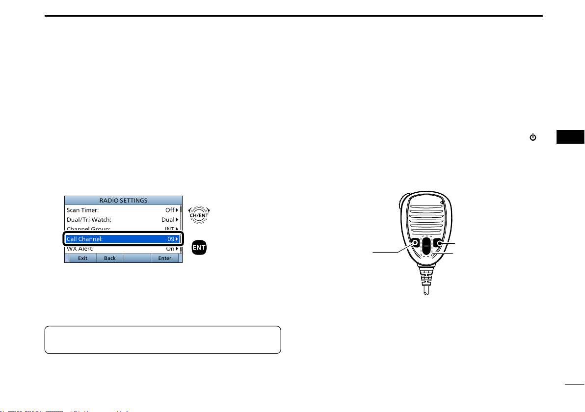
■ Setting the Call channel
By default, a Call channel is set in each Channel Group.
You can set the Call channel with your most often-used
channel for quick recall.
1. Push [MENU].
• The “MENU” screen is displayed.
2. Rotate [CH/ENT] to select “Radio Settings,” then push
[ENT].
3. Rotate [CH/ENT] to select “Call Channel,” then push
[ENT].
• The “CALL CHANNEL” screen is displayed.
4. Rotate [CH/ENT] to select a channel to be set as the
Call channel, then push [ENT].
5. Push [MENU] to return to the Main screen.
TIP:
To conrm that your setting is correctly set, hold
down [16/C] for 1 second. (p. 14)
Rotate
+
Push
■ Microphone Lock function
The Microphone Lock function electrically locks [∫], [√],
[16/C] and [H/L] on the supplied microphone.
This prevents accidental channel changes or function access.
While holding down [H/L] on the microphone, hold down [ ]
for 1 second to turn ON the transceiver.
• The Microphone Lock function is turned ON or OFF.
[16/C]
[H/L]
[∫], [√]
1
2
3
4
5
6
7
8
9
10
11
12
13
14
15
16
17
5
BASIC OPERATION
■ Receiving and transmitting
18
CAUTION: DO NOT transmit without an antenna. It will
damage the transceiver.
1. Hold down [ ] for 1 second to turn ON the transceiver.
L If no MMSI code is entered, “Push [ENT] to Register Your
MMSI” is displayed. (p. 9)
2. Rotate [VOL/SQL] to adjust the audio level.
3. Push [VOL/SQL] once or twice to open the “SQL
Setting” window, then rotate [VOL/SQL] to adjust the
squelch level until the noise just disappears.
4. Select a channel. (p. 14)
InformationL
• When receiving a signal, “ ” is displayed.
• You can use Channel 70 only for Digital Selective Calling
(DSC) transmissions.
•
When the “FAV on MIC” item is set to “OFF,” you can select all
channels using the [∫] or [√] keys on the microphone. (p. 6)
5. Push [Ω] or [≈] until “HI/LO” is displayed in the
Software Key area.
6. Push [HI/LO] to select an output power high or low.
InformationL
• “25W” is displayed when high power is selected. Choose high
power for longer distance communications.
• “1W” is displayed when low power is selected. Choose low
power for short range communications.
• Some channels are restricted to low power.
7. Hold down [PTT], and speak at your normal voice level.
• “ ” is displayed.
8. Release [PTT] to return to receive.
IMPORTANT: To maximize the readability of your
transmitted signal at a receiver station, pause a second
after pushing [PTT], and then hold the microphone 5 to
10 cm from your mouth and speak at your normal voice
level.
NOTE for the Time-out Timer (TOT) function:
The TOT function inhibits continuous transmission beyond
a preset time period after the transmission starts.
10 seconds before transmission is cut off, a beep sounds
to indicate the transmission will be cut off, and “TOT” blinks
in the channel name eld. After it is cut OFF, "TIME OUT"
is displayed for 10 seconds. And you cannot transmit until
"TIME OUT" disappears.
5
6
1
4
2, 3
Microphone
7, 8
6
4
BASIC OPERATION
5
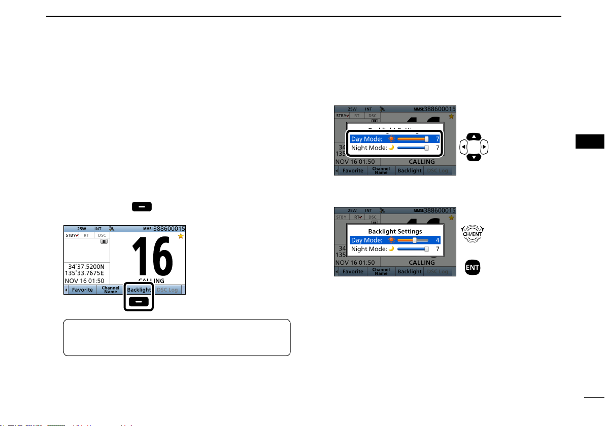
■ Backlight function
The function display and keys can be backlit for better
visibility under low light conditions. And, you can set the
Backlight mode to Day mode or Night mode.
The Day mode is for the daytime operation, and the screen items
are in color.
The Night mode is for the nighttime operation, and the
screen items are in black and red.
1. Push [Ω] or [≈] until “Backlight” is displayed in the
Software Key area.
2. Push [Backlight]
window.
Push
TIP: In the “Backlight Setting” window, if you push no
key for about 5 seconds, the transceiver automatically
returns to the Normal operation mode.
to open the “Backlight Settings”
3. Push [∫] or [√] to select “Day Mode” or “Night Mode.”
Push
4. Rotate [CH/ENT] to adjust the backlight level, then
push [ENT].
Rotate
+
Push
L The backlight level is adjustable in 7 levels and “OFF.”*
* “OFF” is selectable only for the Day mode.
1
2
3
4
5
6
7
8
9
10
11
12
13
14
15
16
19
5
BASIC OPERATION
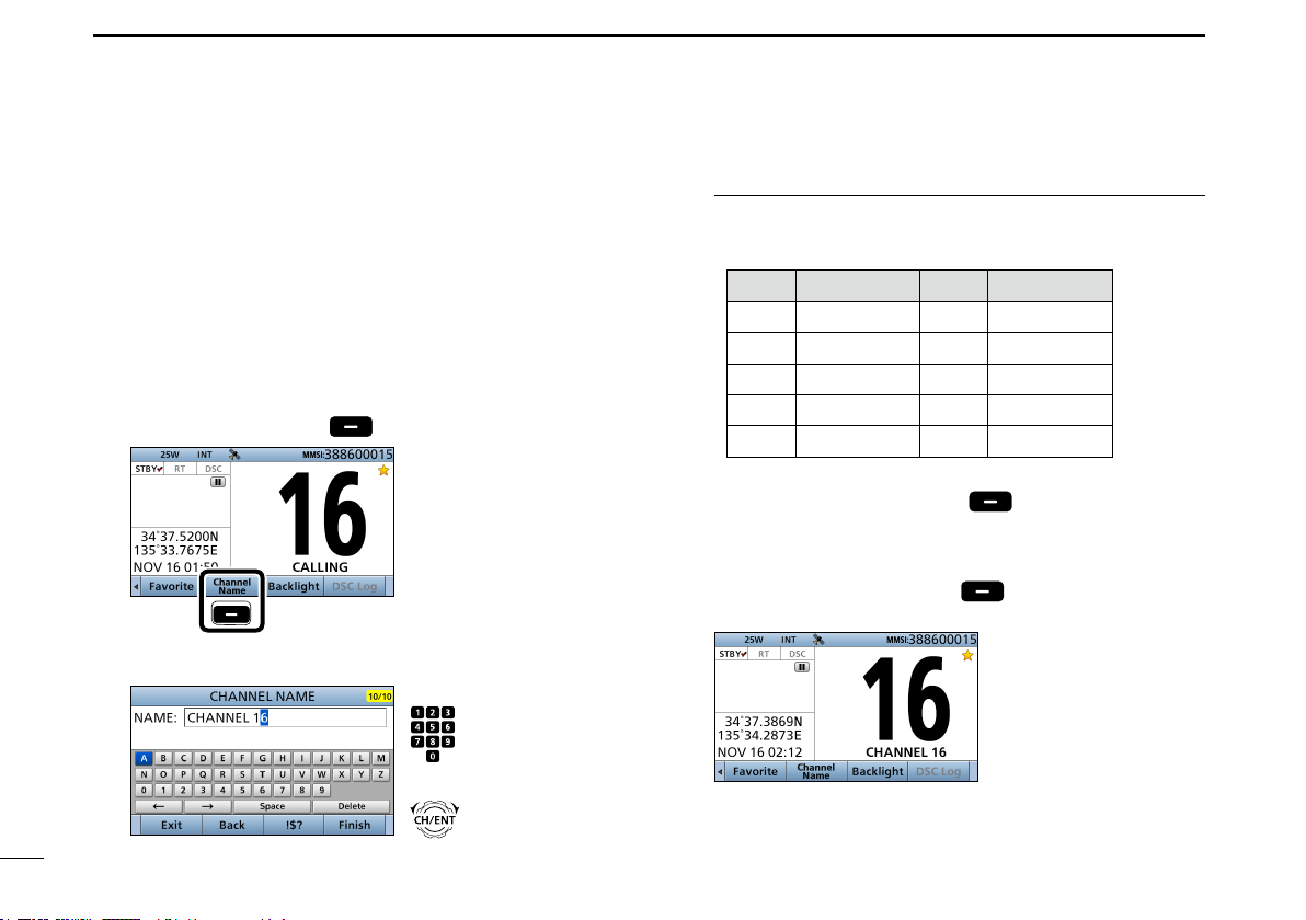
■ Entering a Channel name
You can rename each channel with a unique alphanumeric
ID of up to 10 characters. This may be helpful to indicate the
frequency's use.
1.
Cancel the Dualwatch, Tri-watch or Scan function, if
activated.
2. Select a channel. (p. 17)
3. Push [Ω] or [≈] until “Channel Name” is displayed in the
Software Key area.
4. Push [Channel Name]
Push
5. Enter a channel name.
.
Push
+
Rotate
InformationL
• You can enter the following characters by pushing the keypad
one or more times.
KEY ENTRY KEY ENTRY
[1] 1 [6] 6 M N O
[2] 2 A B C [7] 7 P Q R S
[3] 3 D E F [8] 8 T U V
[4] 4 G H I [9] 9 W X Y Z
[5] 5 J K L [0] 0 . (period)
• To move the cursor, rotate [CH/ENT].
• To enter a symbol, push [“
[Z], [Ω], or [≈] to select the character, then push [ENT].
• To correct an entry, move the cursor to the character, and
then enter the correct character.
6. After entering, push [Finish] to return to the Main
screen.
!$?
”] . And then push [Y],
20
 Loading...