

Page 1

INSTRUCTION MANUAL
iC- m59
VHF MARINE TRANSCEIVER
Page 2

IN CASE OF EMERGENCY
i
If your vessel requires assistance, contact other vessels and
the Coast Guard by sending a distress call on channel 16.
Or, transmit your distress call using digital selective calling on
channel 70 (the optional UX-120
DSC UNIT
must be installed).
❍
USING CHANNEL 16
DISTRESS CALL PROCEDURE
1. “MAYDAY MAYDAY MAYDAY”
2. “THIS IS - - - - - - - - - - - - - - ” (name of vessel)
3. Your call sign or other indication of the vessel
(AND 9-digit DSC ID if you have one).
4. “LOCATED AT - - - - - - - - - - ” (your position)
5. The nature of the distress and assistance required.
6. Any other information which might facilitate the
rescue.
❍
USING DIGITAL SELECTIVE CALLING (ch 70)
(UX-120 required)
DISTRESS CALL PROCEDURE
1. Push and hold [16•
EMER
] for 5 sec. until you
hear 5 short beeps change to one long beep.
2. Then, push [PTT] to transmit the call.
3. Wait for an acknowledgment from a coast station.
• When received, channel 16 is automatically selected.
4. Push and hold [PTT], then transmit the appropriate information as at left.
Page 3

ii
TABLE OF CONTENTS
IN CASE OF EMERGENCY ..................................................i
TABLE OF CONTENTS ...................................................... ii
IMPORTANT ...................................................................... iii
CAUTIONS.......................................................................... iii
1 OPERATING RULES ..................................................... 1
2 PANEL DESCRIPTION ............................................ 2 – 5
■ Front panel ................................................................. 2
■ Microphone ................................................................. 3
■ Function display .......................................................... 4
3 BASIC OPERATION .............................................. 6 – 11
■ Power ON ................................................................... 6
■ Channel selection ....................................................... 6
■ Receiving .................................................................... 8
■ Transmitting ................................................................ 9
■ Scan function ............................................................ 10
■ Call channel programming ........................................ 11
■ Display backlighting .................................................. 11
4 DIGITAL SELECTIVE CALLING ......................... 12 – 18
■ General ..................................................................... 12
■ Distress call transmission ......................................... 13
■ All ships call transmission ......................................... 14
■ Individual call transmission ....................................... 15
■ Receiving DSC calls ................................................. 16
5 SET MODE ........................................................... 19 – 21
■ Entering SET mode .................................................. 19
■ SET mode items ....................................................... 19
6 CONNECTIONS AND MAINTENANCE .............. 22 – 27
■ Unpacking ................................................................ 22
■ Additional requirements ............................................ 22
■ Connections .............................................................. 23
■ Mounting the transceiver .......................................... 24
■ Dimensions ............................................................... 25
■ Antenna .................................................................... 26
■ Fuse replacement ..................................................... 26
■ Cleaning ................................................................... 26
■ Optional unit installations .......................................... 26
7 TROUBLESHOOTING ................................................ 28
8 VHF MARINE CHANNEL LIST ................................... 29
9 SPECIFICATIONS ....................................................... 30
10 OPTIONS ................................................................... 31
Page 4

WHEN INSTALLING THE DSC UNIT
NEVER transmit a distress call when your vessel does not
need immediate help. Distress calls can be used only in times
of emergency.
AVOID using or placing the transceiver in direct sunlight or
in areas with temperatures below –20°C (–4°F) or above
+60°C (+140°F).
DO NOT operate the transceiver without running the ves-
sel’s engine. When your vessel’s engine is OFF and the
transceiver is transmitting, the vessel’s battery will soon become exhausted.
KEEP the transceiver out of the reach of children.
KEEP the antenna cable and DC power cable as far away
as possible from electrical pumps, generators and other electronic instruments to prevent instrument malfunctions.
KEEP the transceiver and microphone at least 1 meter
away from your vessel's magnetic navigation compass.
iii
IMPORTANT
READ ALL INSTRUCTIONS carefully and com-
pletely before using the transceiver.
SAVE THIS INSTRUCTION MANUAL—This in-
struction manual contains important operating instructions for
the IC-M59.
YOU MUST HAVE a DSC vessel ID in order to oper-
ate the optional DSC functions of the transceiver. See your
Dealer for details.
CAUTIONS
RWARNING NEVER connect the transceiver to an
AC outlet. This may pose a fire hazard or result in an electric
shock.
RWARNING HIGH VOLTAGE! NEVER touch
the antenna or an internal antenna connector during transmission. This may result in an electric shock or a burn.
NEVER connect the transceiver to a power source of more
than 16 V DC. This connection will ruin the transceiver.
Page 5

OPERATING RULES
1
1
D Priorities
• Read all rules and regulations pertaining to priorities and
keep an up-to-date copy handy. Safety and distress calls
take priority over all others.
• You must monitor channel 16 when you are not operating
on another channel.
• False or fraudulent distress calls are prohibited under law.
D Privacy
• Information overheard but not intended for you cannot lawfully be used in any way.
• Indecent or profane language is prohibited.
D Radio licenses
SHIP STATION LICENSE
When your craft is equipped with a VHF FM transceiver, you
must have a current radio station license before using the
transceiver. It is unlawful to operate a ship station which is not
licensed.
Inquire through your dealer or the appropriate government
agency for a Ship-Radiotelephone license. This license includes the call sign which is your craft’s identification for radio
purposes.
OPERATOR’S LICENSE
A restricted Radiotelephone Operator Permit is the license
most often held by small vessel radio operators when a radio
is not required for safety purposes.
The Restricted Radiotelephone Operator Permit must be
posted near the transceiver or be kept with the operator. Only
a licensed radio operator may operate a transceiver.
However, non-licensed individuals may talk over a transceiver
if a licensed operator starts, supervises, ends the call and
makes the necessary log entries.
A current copy of the applicable government rules and regulations is only required to be on hand for vessels in which a
radio telephone is compulsory. However, even if you are not
required to have these on hand it is your responsibility to be
thoroughly acquainted with all pertinent rules and regulations.
Page 6
PANEL DESCRIPTION
2
2
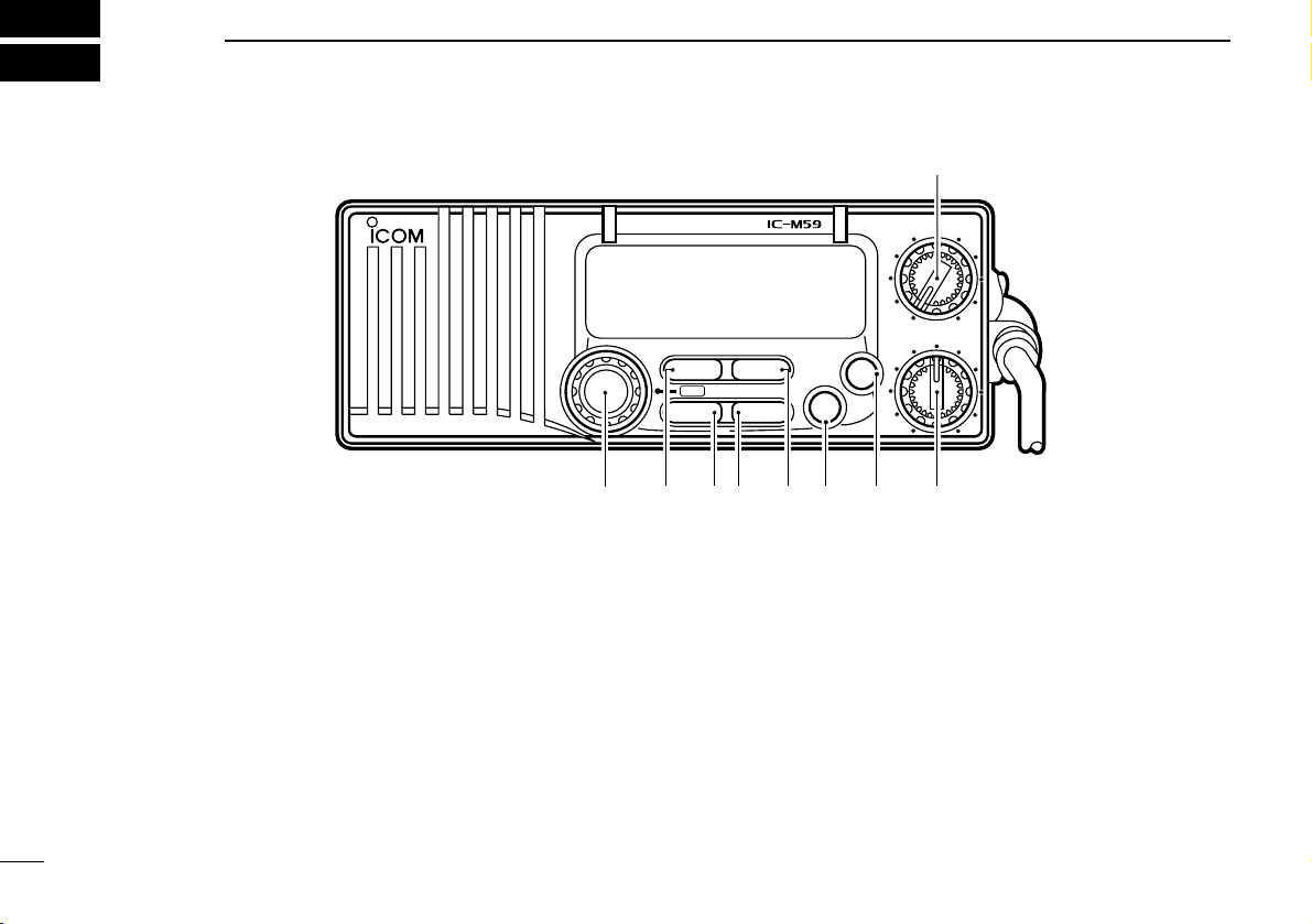
➊ CHANNEL SELECTOR [CHANNEL]
Selects an operating channel in the selected channel
group.
➋ SCAN SWITCH [SCAN•TAG]
• Starts and stops normal or priority scan when tag channels are programmed. (p. 10)
• Push and hold for 1 sec. to toggle the tag setting for the
displayed channel. (p. 10)
➌ HIGH/LOW POWER SWITCH [HI/LO•DIM]
• Toggles between high and low output powers. (p. 9)
• While pushing, rotate the channel selector to adjust the
display and control/switch backlighting intensity. (p. 11)
➍ CHANNEL/WEATHER CHANNEL SWITCH
[CH/WX•
U/I/C]
• Selects and toggles between regular and weather channels.
• Selects one of 3 regular channels in sequence when
pushed for 1 sec. (p. 7)
➠ International, U.S.A. and Canadian channels are available for
regular channels.
➎ DUAL/TRI-WATCH SWITCH [DUAL•TRI] (p. 8)
• Activates dualwatch for checking channel 16.
VHF
TAG TRI
U/I/CDIM
ALL
/IND
EMER
16
9
SQUELCH
OFF
PWR/VOL
SCAN
HI/LO CH/WX
DUAL
MARINE
➋➌
➍
➎➏ ➐ ➑
➒
➊
■ Front panel
Page 7
■ Microphone
HI/LO
➊
➋
2
PANEL DESCRIPTION
3
• Push and hold for 1 sec. to activate tri-watch for checking
channel 16 and the call channel.
➏ CALL CHANNEL SWITCH [9•ALL/IND]
• Selects the call channel—the call channel is programmable, channel 9 being the default. (p. 11)
• Push and hold for 1 sec. to enter the standby condition of
a DSC call. (When an optional UX-120 is installed).
(pgs. 14, 15)
➠ Both “All ships call” and “Individual call” are selectable.
➐ CHANNEL 16 SWITCH [16•EMER]
• Selects channel 16. (p. 6)
• Push and hold to enter the standby condition for a dis-
tress call transmission using the DSC function (when an
optional UX-120 is installed). (p. 13)
➑ SQUELCH CONTROL [SQUELCH]
• Rotate clockwise to eliminate audio noise. (p. 8)
• Activates the built-in attenuator when rotated deep clock-
wise. (p. 8)
➒ POWER/VOLUME CONTROL [PWR/VOL]
Turns power ON and OFF and adjusts the audio output
level. (p. 6)
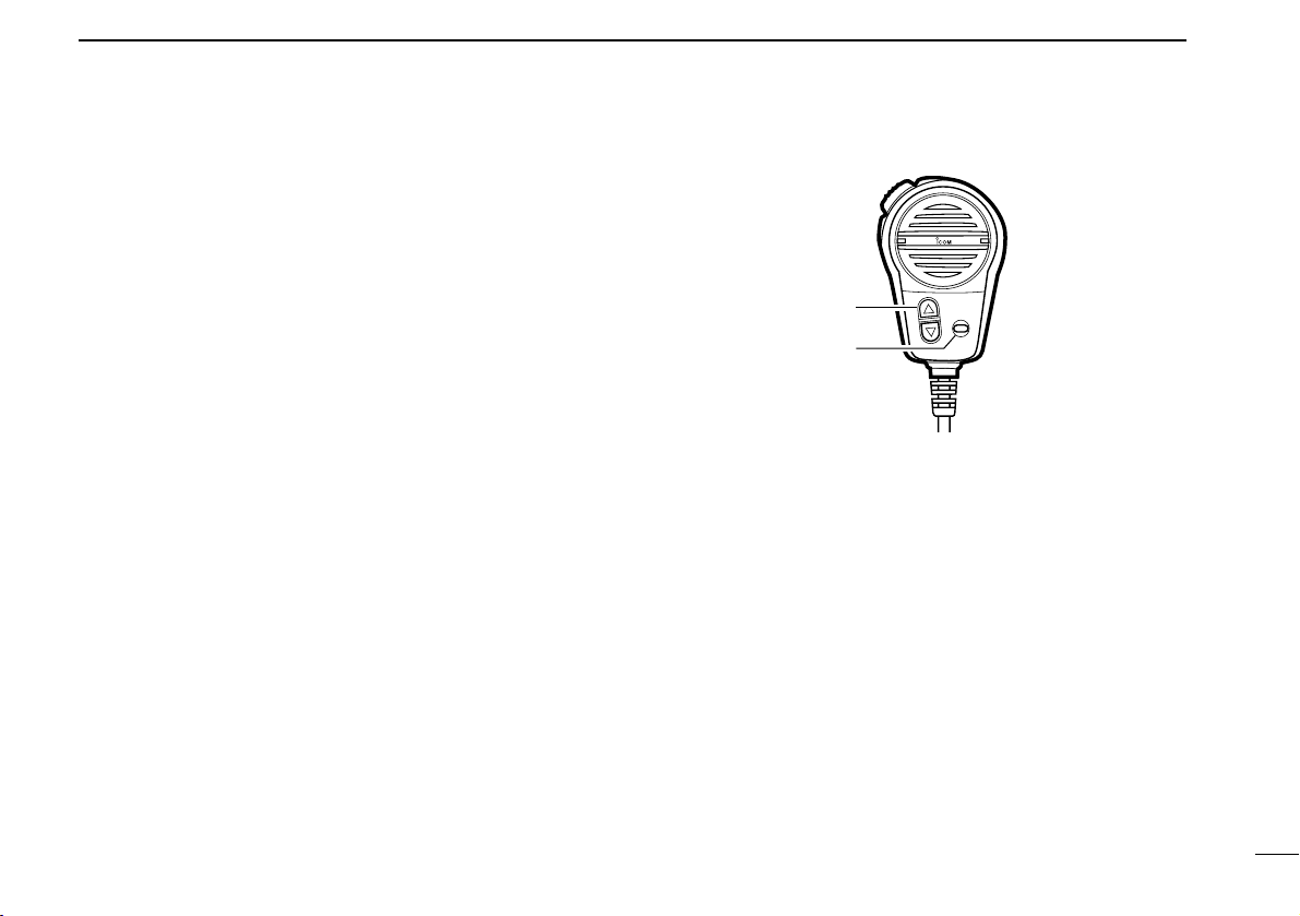
➊ CHANNEL UP/DOWN SWITCHES [▼]/[▲]
• Select an operating channel in the selected channel
group.
➠ These switches can be used instead of the transceiver’s
channel selector.
➋ HIGH/LOW POWER SWITCH [HI/LO]
The same function as the transceiver’s front panel.
• Toggles between high and low output powers. (p. 9)
• While pushing, push the [▼]/[▲]
switches to adjust the display
and control/switch backlighting intensity. (p. 11)
Page 8
2
PANEL DESCRIPTION
4
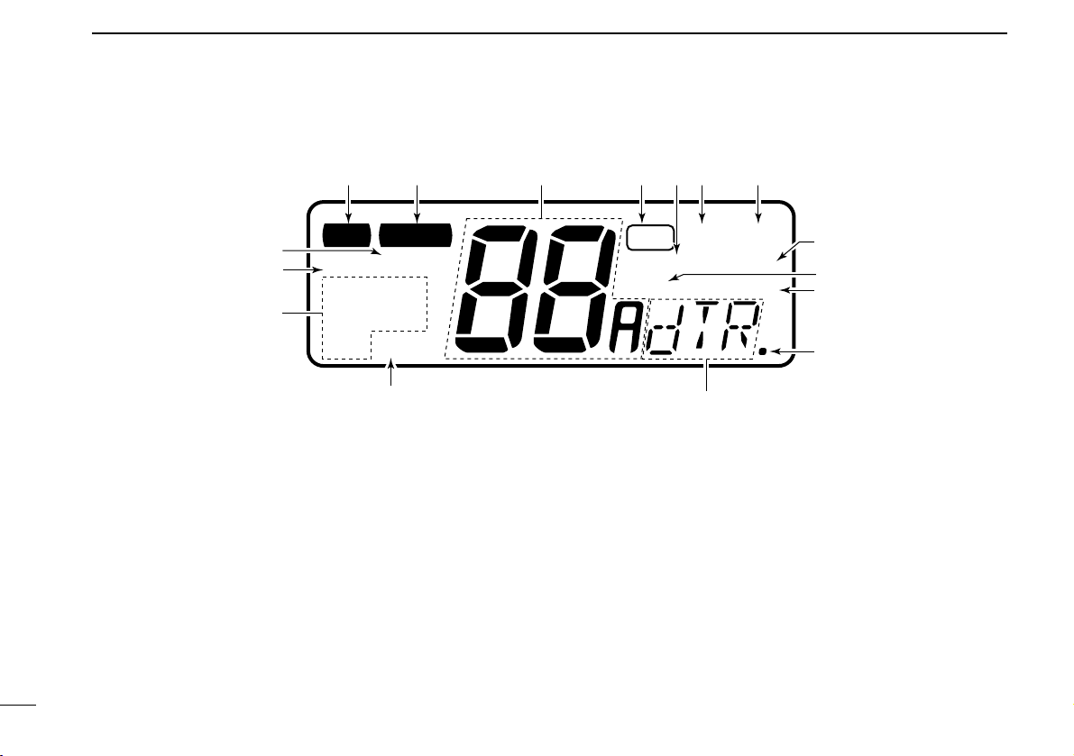
q TRANSMIT INDICATOR
Appears while transmitting. (p. 9)
w BUSY INDICATOR
Appears when receiving a signal or when [SQUELCH] is
rotated too far counterclockwise. (p. 8)
e CHANNEL INDICATOR
Shows the operating channel. (pgs. 6, 7)
r TAG CHANNEL INDICATOR
Appears when the selected channel is set as a tag channel. (p. 10)
t SCAN INDICATOR
Appears and flashes during scan operation. (p. 10)
y DUALWATCH INDICATOR
Appears and flashes during dualwatch operation. (p. 8)
u TRI-WATCH INDICATOR
Appears and flashes during tri-watch operation. (p. 8)
i VOICE SCRAMBLER INDICATOR
Appears while the optional voice scrambler is activated.
(p. 8)
LOW CALL
CANUSA
INT
ALTWX
TX
TAG
DUAL
SCAN
DUP ACK RCV
SCRM
TRI
BUSY
qewrtyu
i
o
!0
!1
!2
!3
!4
!5
!6
■ Function display
Page 9

5
2
PANEL DESCRIPTION
o DUPLEX INDICATOR
Appears when the selected channel is a duplex channel.
!0 ACKNOWLEDGEMENT/RECEIVE INDICATORS
Appear during optional DSC operation. (pgs. 13–18)
• “RCV” appears when a DSC call is received.
•“ACK RCV” appears when an acknowledgement is received.
•“ACK” and “$” appear when transmitting an acknowledge-
ment.
!1 DSC INDICATORS (pgs. 13–18)
Appear during optional DSC operation and show a format
specifier, message, etc.
!2 NMEA INDICATOR
Appears when NMEA devices (such as a GPS receiver)
are connected. (p. 12)
!3 WEATHER ALERT INDICATOR
Indicates the weather alert function is activated. (p. 7)
!4 MODE INDICATORS (p. 7)
•“USA” shows USA channels are selected.
•“CAN” shows Canadian channels are selected.
•“INT” shows International channels are selected.
•“WX” shows weather channels are selected.
!5 LOW POWER INDICATOR
Shows that low output power is selected. (p. 9)
!6 CALL CHANNEL INDICATOR
Appears when the call channel is selected. (p. 6)
Page 10
■ Channel selection
D Channel 16
Channel 16 is the distress channel. It is used for establishing
initial contact with another station and for emergency communications. Channel 16 is monitored during dualwatch/triwatch. While standing by you are required to monitor channel
16.
D Call channel
The call channel is used to store your most often-used channel for quick recall. In addition, the call channel is monitored
during tri-watch. The default setting for the call channel is
channel 9 which is for pleasure use.
BASIC OPERATION
3
6
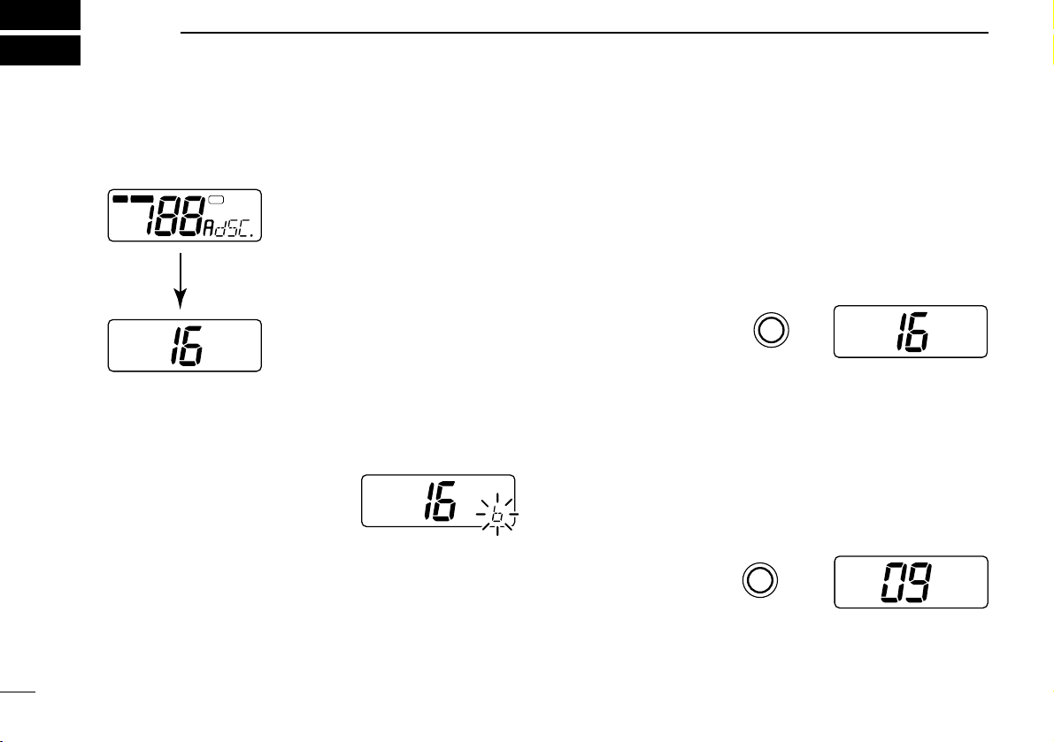
■ Power ON
➀ Rotate [PWR/VOL] clockwise to turn power ON.
➁ Operate the transceiver as indicated in the following sec-
tions.
D Low voltage indicator
When “b” appears and flashes as
shown at right, there is a DC power
source problem. In this case, check
your vessel’s battery and DC
power cable.
LOW CALL
CANUSA
USA
INT
ALTWX
TX
TAG
DUAL
SCAN
DUP ACK RCV
SCRM
TRI
BUSY
All display indications
appear briefly*.
*“SCRM” appears only when an optional
UT-79 is installed.
“dSC” appears only when an optional
UX-120 is installed.
USA
Push
or hang the microphone
on the microphone hanger.
16
Push
CALL
USA
“CALL” indicates that the
call channel is selected.
9
USA
Page 11
3
BASIC OPERATION
7
D U.S.A., Canadian and international channels
There are 61 U.S.A., 57 Canadian and 57 international channels. These channel groups may be specified for the operat-
ing area.
➀ Push [CH/WX] to select a regular channel.
• If a weather channel appears, push [CH/WX] again.
➁ Rotate the channel selector to select a channel.
•“DUP” appears for duplex channels.
➂ To change the channel group, push [CH/WX•U/I/C] for 1
sec.
• U.S.A., Canadian and international channels can be selected in
sequence.
D Weather channels
There are 10 weather channels. These are used for monitoring NOAA (National Oceanographic and Atmospheric
Administration) weather broadcasts.
✔ CONVENIENT
Weather alert function: NOAA broadcast stations transmit
a weather alert tone before an important weather announcement.
When the weather alert function is turned ON, the “ALT” indicator flashes until any key is pushed.
This function is activated when a weather channel is selected
or during any scan. See “SET mode items” on p. 19.
USA
INT
DUP
CAN
TAG
U.S.A. channels
Push for 1 sec.
International channels Canadian channels
U/I/C
CH/WX
Push
once or twice
WX
CH/WX
Page 12

3
BASIC OPERATION
8
■ Receiving
➀ Rotate [PWR/VOL] to turn power ON.
➁ Rotate [SQUELCH] fully counterclockwise.
➂ Adjust [PWR/VOL] to a suitable listening level.
➃ Rotate [SQUELCH] clockwise until the audio noise disap-
pears.
➄ Select the desired channel. See pgs. 6–7 for details.
• When a signal is received:
➧ The squelch opens;
➧ Audio is emitted from the speaker;
➧ “BUSY” appears in the function dis-
play.
➅ When an interrupting signal is received; rotate [SQUELCH]
deeply clockwise.
D Voice scrambler function
For confidential communications, use the optional voice
scrambler function. All members of your group must have the
UT-79
VOICE SCRAMBLER UNIT
installed in order to communi-
cate using this function.
➥ While pushing [HI/LO], push
[CH/WX] to toggle the function ON
and OFF.
•“SCRM” appears when the function is ON.
• This function cannot be used on CH 16.
• Set the scramble code in SET mode in advance (p. 19).
BUSY
USA
SCRM
D Dual/tri-watch functions
These functions allow you to conveniently check the distress
channel (ch 16) or, both the distress and pleasure call channel (ch 9; programmable) while receiving another channel.
When receiving a signal on one of these channels, the transceiver stops on the channel until the signal disappears.
➥ Push [DUAL•
TRI] momentarily for dualwatch.
➥ Push and hold [
DUAL•TRI] for tri-watch.
USA
DUAL
USA
DUAL
BUSY
Checking channel 16
every 2 sec.
When receiving a signal
on channel 16. Channel
16 is monitored until the
signal disappears.
USA
TRI
CALL
USA
TRI
BUSY
USA
TRI
BUSY
Checking channel 16
and the call channel
every 2 sec.
When receiving a signal
on channel 16, channel
16 has priority.
When receiving a signal
on the call channel, the
call channel is monitored
while checking ch 16 in
2 sec. intervals.
Page 13

3
BASIC OPERATION
9
■ Transmitting
Before transmitting, read the call procedures at right.
➀ Select an operating channel. See pgs. 6, 7 for details.
➁ Push [HI/LO] to select transmit output power.
•“LOW” appears when low output power is selected.
• High power cannot be selected on some channels. Refer to the
channel list on p. 29.
➂ Push and hold the PTT switch to transmit.
•“$” appears.
➃ Speak into the microphone at your normal voice level.
• Do not hold the microphone too closely to your mouth or speak
too loudly. This may distort the transmit signal.
➄ Release the PTT switch to receive.
IMPORTANT: In order to maximize the readability of your transmitted signal, pause for a moment after pushing [PTT], hold the
microphone 15–20 cm from your mouth, then speak into the microphone at an even, normal voice level.
CALL PROCEDURES
You must identify yourself when you transmit and you must
respect time limits.
1) Give your call sign each time you call another vessel or
a coast station. If you have no call sign, identify the station by giving the vessel name and the name of the license.
2) Give your call sign at the end of each transmission that
lasts more than 3 minutes.
3) You must pause and give your call sign at least once
every 15 minutes during long ship-to-shore calls.
4) Keep your calls short (less than 3 minutes). Wait 2 minutes before repeating a call.
5) Unnecessary transmissions are not allowed.
TIME-OUT TIMER (U.S.A. version only)
The transceiver has a time-out timer function to prevent
continuous, long transmissions. Transmit is automatically
inhibited after 5 min. of continuous transmission.
MOMENTARY HIGH POWER
On U.S.A. channels 13, 15 and 67, transmission using high
power is momentarily possible. To use high power, push
and hold [HI/LO] while transmitting.
Page 14

3
BASIC OPERATION
10
■ Scan function
The transceiver has a high speed scan function for standing
by on utility signals. The scan speed is 8 channels/sec. (except when the weather alert function is in use).
Two scan types are available:
normal scan (scans all tag
channels in sequence) and
priority scan (checks channel 16
while scanning). These scans can be selected in set mode
(p. 19).
D Setting tag channels
You can specify channels as tag channels for efficient scanning. Tag channels can be set for each channel group (USA,
CAN, INT) independently.
➥ Select the desired channel, then push and hold
[
SCAN•TAG] for 1 sec. to toggle the tag setting.
✔ Clearing all tag channels:
While pushing [HI/LO], push and hold [
SCAN•TAG] for 3 sec.
until the long beep becomes 2 short beeps.
• All tag channels in the selected channel group are released.
USA
TAG
Appears when the channel is
specified as a tag channel.
D Scan operation
➀ Select the desired channel group (USA, CAN, INT) or WX
channels with [
CH/WX•U/I/C].
• When the weather alert function is in use, select the desired WX
channel in the display, then perform the above operation.
➁ Push [SCAN] to start scanning.
•“SCAN” appears and flashes in the function display.
•“16” appears during priority scan.
➂ To stop the scan, push [SCAN] again.
•“SCAN” disappears.
✔ Scan resume timer:
When a signal is detected, scan pauses until the signal disappears or resumes after pausing 5 sec., according to the set
mode setting. (p. 19)
✔ Confirming tag channels:
While operating scan, rotate [DIAL].
• Only tag channels are selected.
• Stop rotating [DIAL] to resume scan.
✔ Weather alert function:
When the function is turned ON (p. 19), the selected weather
channel is checked during scan. Refer to p. 7 for a description of weather alert.
Page 15

3
BASIC OPERATION
11
■ Call channel programming
The call channel key, [9], is used to select channel 9, however, you can program your most often-used channels in
each channel group for quick recall.
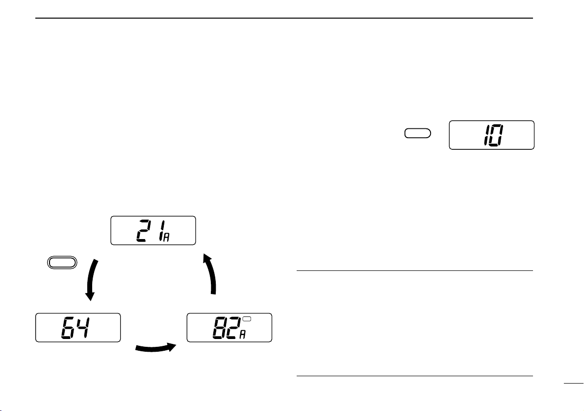
➀ Push [CH/WX•U/I/C] for 1 sec.
one or more times to select
the desired channel group
(USA, INT, CAN) to be programmed.
➁ Push [9] to select the call
channel of the selected channel group.
•“CALL” and the call channel
number appear.
➂ While pushing [HI/LO] push [9]
to enter call channel write
mode.
• Call channel number and channel group to be programmed flash.
➃ Rotate the channel selector to
select the desired channel.
➄ Push [9] again to program the
displayed channel as the call
channel.
• The call channel number and
channel group stop flashing.
■ Display backlighting
The function display and switches can be backlit for better
visibility under low light conditions.
While pushing [
HI/LO•DIM], rotate the channel selector to ad-
just the backlighting.
➥ Backlighting can be set to 1 of 3 intensities or turned OFF.
USA
CALL
USA
TAG
CALL
USA
CALL
USA
CALL
USA
Page 16

DIGITAL SELECTIVE CALLING
4
12
■ General
When an optional UX-120
DSC UNIT
is installed, digital selective calling (or DSC) can be used via the IC-M59. DSC is a
method of radio communications involving digital signals
rather than the more conventional method of voice communications. The advantage of using digital communications
over voice communications is that information (especially
useful for distress calls and other urgent matters) can be preprogrammed into a radio and transmitted accurately.
UX-120 required
In addition, when a GPS receiver (NMEA0183 ver. 1.5, 2.0 or
2.1) is connected, your vessel’s position and the current UTC
time are transmitted together with the vessel’s identity when
making a distress call.
See p. 27 for unit installation.
DSC TYPE DESCRIPTION REF.
Distress call
This sends distress information which includes your vessel’s ID (and position data/UTC time
when a GPS receiver is connected). Send under emergency conditions only. DSC acknowledgement will be received from a coast station after making a distress call.
pgs.
13, 16
Distress relay call
This is used to alert Coast stations (or other ships) when a vessel in distress is unable to do
so. The IC-M59 can only receive this type of signal; not transmit.
p. 16
All ships call
This is used for non-emergency situations. This signal includes information which allows a receiving transceiver to automatically select a specified channel for voice communication.
pgs.
14, 16
Individual call
This allows you to send a signal to a specific vessel only. The vessel’s ID code must be pre-
programmed in advance. Two kinds of acknowledgements (able to comply/unable to comply)
are available (for sending or receiving) after an individual call.
pgs.
15, 17
Geographical area call
This is used for announcement to all ships in the specified area—when a GPS receiver is
connected calls directed to areas other than yours are rejected. Receive only for the IC-M59.
p. 17
Page 17

➃ When a distress acknowledge-
ment is received, emergency
alarm sounds and channel 16
is automatically selected.
• Push any key to cancel the
alarm.
➄ Transmit your distress call particulars by voice using the
following procedure:
1. “MAYDAY.”
2. “THIS IS ” (name of vessel).
3. The 9-digit identity AND the call sign (or other identification
of the vessel).
4. The vessel’s position if DSC does not include it.
5. The nature of the distress and assistance required.
6. Any other information which might facilitate the rescue.
NOTE: When a GPS receiver (NMEA 0183) is connected,
your vessel’s position is automatically transmitted with the
distress call.
NOTE: Acknowledgement of a DSC distress alert is normally made by coast stations only.
4
DIGITAL SELECTIVE CALLING
13
■ Distress call transmission
CAUTION: Distress calls may be transmitted under
conditions of emergency only i.e. your vessel is in danger
of sinking and/or a person’s life is in danger.
➀ Push and hold [16•EMER] until
you hear 4 short beeps
change to one long beep.
• The display changes as at right.
➁ Push [PTT] to transmit the dis-
tress call.
➂ The transceiver remains on channel 70 until an acknowl-
edgement is received.
• When no acknowledgement is received, the distress call is repeated until an acknowledgement is received.
• To cancel this, turn power OFF then ON again.
• Calls to you other than distress acknowledgement cannot be re-
ceived.
INT
INT
LOW
LOW
INT
TX
INT
INT
ACK RCV
BUSY
ACK RCV
LOW
Page 18

4
DIGITAL SELECTIVE CALLING
14
■ All ships call transmission
Large ships use channel 70 as their “listening channel.” When
you want to announce a message to these ships, use the “all
ships call” function.
➀ Select a simplex channel for
the traffic channel (for voice
communication after sending
the all ships call).
• Some ‘A’ channels (eg. channel 88A) cannot be used.
➁ Rotate [SQUELCH] clockwise until the audio noise disap-
pears.
➂ While pushing [9•ALL/IND] ro-
tate the channel selector to select “ALL” as at right.
➃ Push and hold [9•ALL/IND]
until you hear 4 short beeps
change to one long beep.
• The display changes as at right.
➄ Push [PTT] momentarily to
transmit the all ships call.
• After transmission, the channel
set in step ➀ above is selected.
USA
LOW
USA
LOW
USA
USA
LOW
USA
TX
➅ Push and hold [PTT] again to send an announcement to
all ships.
NOTE: Channel busy
When channel 70 is busy, the
all ships call is not transmitted. The transceiver waits
until the channel is clear, then
transmits the call automatically.
NOTE: Error indication
When a transmission inhibited
channel (e.g. ch 70) is selected for the traffic channel,
the display at right appears. In this case, an appropriate
channel must be selected.
This display may also appear if [9•ALL/IND] is accidentally
released early while being pushed and held in step ➂.
LOW
USA
BUSY
This display appears
while the call is in
standby.
LOW
USA
Page 19

4
DIGITAL SELECTIVE CALLING
15
■ Individual call transmission
The individual call function allows you to transmit a DSC signal to a specific party only.
➀ Set the ID code for the individual you wish to call in ad-
vance.
• This code is input into the address item in SET mode. (p. 19)
➁ Select the traffic channel (for
voice communication after the
individual call is sent).
• Select a simplex channel (some
‘A’ channels cannot be used) for ship-to-ship contact.
• Select a duplex channel for ship-to-coast contact.
➂ Rotate [SQUELCH] clockwise until the audio noise disap-
pears.
➃ While pushing [9•ALL/IND] rotate the channel selector to
select “Ind” as at right.
• When no address ID is pre-programmed, “Ind” cannot be selected.
➄ Push and hold [9•ALL/IND]
until you hear 4 short beeps
change to one long beep.
• The display changes as at right.
• When “ALL” appears instead of
“Ind,” rotate the channel selector
to select “Ind” while pushing [9•ALL/IND].
➅ Push [PTT] momentarily to transmit the individual call.
•“HIGH” power is automatically selected while transmitting the call.
➆ Standby on channel 70 until an acknowledgement is re-
ceived.
➇ When the acknowledgement is
received, the display changes
as at right.
• Beeps sound.
• The channel set in step ➁ is se-
lected.
➈ Push and hold [PTT] to communicate your message to the
responding party.
NOTE: Unable to comply
When the received acknowledgement includes “unable to
comply,” the message display
changes as at right. In such a
case, wait at least 5 min. before re-transmitting the call.
NOTE: Channel busy error indication
The same as for the all ships call. Refer to the page opposite for details.
USA
LOW
LOW
USA
USA
LOW
USA
BUSY
USA
ACK RCV
ACK RCV
USA
USA
ACK RCV
ACK RCV
LOW
Page 20

4
DIGITAL SELECTIVE CALLING
16
■ Receiving DSC calls
Several types of DSC transmissions can be received. The required action depends on the particular DSC type as outlined
in the following examples. However, in all examples, you must
be monitoring channel 70 in order to receive such signals.
NOTE: When channel 70 is set as a tag channel and scan
is functioning, DSC calls will not be received. DSC calls
can only be received when channel 70 is selected.
D Receiving a distress call
While monitoring channel 70 and a distress call is received:
➥ Emergency alarm sounds.
➥ “RCV” and “dTR” appear in
the display; then, channel 16
is automatically selected.
➥ Push [16] to stop the alarm.
➥ Continue monitoring channel
16 as a coast station may require assistance in any rescue attempt.
INT
INT
RCV
BUSY
RCV
LOW
D Receiving a distress relay call
A distress relay call may be transmitted from a large ship to a
coast station. While monitoring channel 70 and a distress
relay call is received:
➥ Emergency alarm sounds.
➥ “RCV” and “RLY” appear in the
display; then, channel 16 is
automatically selected.
➥ Push [16] to stop the alarm.
➥ Monitor channel 16 until the
emergency communication
has been completed.
D Receiving an all ships call
While monitoring channel 70 and an all ships call is received:
➥ Emergency alarm or beeps
sound depending on the received category.
➥ “RCV” and “ALL” appear in the
display; then, the channel
specified by the calling station
is automatically selected for
voice communications.
➥ Monitor the selected channel for an announcement from
the calling vessel.
INT
INT
RCV
BUSY
RCV
LOW
INT
INT
RCV
BUSY
RCV
LOW
Page 21

D Receiving a geographical area call
While monitoring channel 70 and a geographical area call (for
the area you are in) is received:
➥ Emergency alarm or beeps
sound depending on the received category.
➥ “RCV” and “GEO” appear in
the display; then, the channel
specified by the calling station
is automatically selected for
voice communications.
➥ Monitor the selected channel for an announcement from
the calling ship.
NOTE: When no GPS receiver is connected or if there is a
problem with the connected receiver, all geographical area
calls are received, regardless of your position.
D Receiving an individual call
When receiving an individual call, an acknowledgement must be
sent back to the calling station within 4.5 min. Operation and
transceiver function differs depending on the SET mode settings.
Two messages can be selected for acknowledgement:
•“Able to comply” ..............You can communicate with the
calling vessel via the mic after a DSC connection.
•“Unable to comply”...........You cannot communicate with
the calling vessel after a DSC connection
(e.g. opera-
tor leaves transceiver).
While monitoring channel 70 and an individual call is
received:
➥ Emergency alarm or beeps sound depending on the re-
ceived category.
➥ “RCV” and “Ind” appear in the
display.
➥ The channel specified by the
calling station is automatically
selected for checking the
channel condition (except
when full automatic acknowledgement is selected).
➥ Proceed as follows on the next page according to your pre-
set conditions.
4
DIGITAL SELECTIVE CALLING
17
USA
RCV
BUSY
USA
LOW
RCV
RCV
USA
USA
RCV
BUSY
LOW
Page 22

4
DIGITAL SELECTIVE CALLING
18
• When semi-automatic (SA; default) or manual (SL) is
selected in SET mode (p. 21):
➀ Push and hold [9•ALL/IND] until
you hear 4 short beeps change
into one long beep to send
“Able to comply” message.
• If you want to send “Unable to
comply” message, or other individual or all ships call, rotate the
channel selector to select them.
➁ Push [PTT] momentarily to
transmit the acknowledgement.
• The channel specified by the calling station is selected.
• When “Unable to comply” is
transmitted in step ➀, the transceiver remains on channel 70.
➂ After receiving a voice transmission, reply via the mic.
Differences between semi-automatic and manual
Semi-automatic: When no operation is performed, the
transceiver automatically
sends an “Unable to comply” acknowledgement 4.5 min.
after the call is received.
Manual: When no operation is performed after receiving a
call, NO acknowledgement is transmitted.
• When full automatic (FA) is selected in SET mode
(p. 21):
➥ The transceiver automatically replies to the call in one of
two ways, depending on the
auto acknowledge setting in
SET mode (p. 21).
• When able to comply is set (Ab),
the transceiver automatically
transmits an able to comply acknowledgement and then selects
the channel as specified by the
calling station for voice communications.
• When unable to comply is set
(Un), the transceiver automatically transmits an unable to comply acknowledgement and
remains on channel 70.
LOW
USA
ACK
LOW
USA
ACK
USA
ACK
USA
RCV
TX
USA
LOW
ACK
USA
ACK
USA
TX
RCV
USA
ACK
USA
TX
ACK
LOW
Page 23

Beep tones (p. 20)
Normal/priority
scan (p. 20)
Weather alert (p. 20)
Scan timer (p. 20)
Address ID (p. 21)
Scramble code (p. 20)
Each push of [16] selects a SET mode item in order.
Acknowledgement
method
(p. 21)
Auto acknowledge
contents (p. 21)
When UX-120 is installed.
When UT-79 is installed.
SET MODE
5
19
■ Entering SET mode
SET mode is used to customize operation of the transceiver
to suit your operating needs.
D To enter SET mode:
➀ While pushing [16], turn power ON.
• Keep pushing [16] until the initial SET mode display appears.
• SET mode is selected.
➁ To exit SET mode, turn power OFF then ON again.
D To select an item:
There are up to 8 items in SET mode (depending on options
installed) that may be adjusted to suit your operating needs.
➀ Select SET mode as above.
➁ Push [16] to select the desired item; then rotate [CHAN-
NEL] to select the desired condition.
• See the following pages for details on each SET mode item.
The diagram at right shows
the default settings for each
SET mode item and the
order of selection.
Items inside dotted lines only
appear when optional units
are installed.
■ SET mode items
Page 24

D SCAN TIMER
This item sets the scan timer ON or OFF.
D SCRAMBLE CODE
This item sets a scramble code for communication using the
optional voice scrambler unit. (p. 8)
5
SET MODE
20
Scramble code “01” Scramble code “127”
Scan timer ON (default) Scan timer OFF
• Scan pauses on a signal
and resumes 5 sec. later.
• Scan pauses on a signal
until the signal disappears,
and resumes 2 sec. after
that.
D BEEP TONES
This item sets the transceiver's confirmation beep tones (when
pushing a switch/rotating [CHANNEL]) ON or OFF.
D NORMAL/PRIORITY SCAN
This item sets the scan function to normal or priority operation.
(See p. 10)
D WEATHER ALERT
This item sets the weather alert function ON or OFF. (p. 7)
Beep tones ON (default)
Beep tones OFF
Normal scan (default) Priority scan
NOTE: Emergency alarm and beeps for DSC operation
cannot be turned OFF.
Weather alert ON (default)
Weather alert OFF
Page 25

10th digit set to “0”
D ADDRESS
This item sets the other station’s 10-digit ID code for individual
calls. Note that your own ID cannot be set in SET mode.
➀ Push [9] to select the digit (1 through 10).
➁ Rotate [CHANNEL] to set the desired value for the selected
digit or turn the individual call OFF.
• Select “–” to clear the digit and turn the individual call OFF.
NOTE: The 10th digit must be
set to “0” when your ID is 9 digits This is reserved for future
use.
5
SET MODE
21
D ACKNOWLEDGEMENT METHOD
This item sets the acknowledgement method for reply to a
calling station when receiving an individual call. (See p. 18)
D AUTO ACKNOWLEDGE CONTENTS
Appears only when full automatic (FA) is selected in the previous item. This item sets “unable to comply” or “able to comply”
as the full automatic acknowledgement transmission. (p. 18)
Full automatic
Semi automatic
Manual
Acknowledgement is transmitted automatically using the specified message.
Acknowledgement can only be transmitted manually.
Acknowledgement is transmitted
manually. If no transmission for 4.5
min., acknowledgement is transmitted automatically using the “Unable to
comply” message.
Able to comply
Unable to comply
[EXAMPLE]: Setting the ID code to 6042737400
Push
9
Page 26

CONNECTIONS AND MAINTENANCE
6
22
■ Unpacking
q Mounting bracket ............................................................ 1
w DC power cable (OPC-632) ........................................... 1
e Microphone hanger (OPC-562) ...................................... 1
r Mounting bracket knobs ................................................. 4
t Mounting screws (5 x 20) ............................................... 4
y Mic hanger screws (3.5 x 30) ......................................... 2
u Flat washers (M4) ........................................................... 2
i Sticker (for scrambler function)* ..................................... 1
* Attach the sticker on the top side of the front panel when the UT-79
is installed.
■ Additional requirements
D FOR GENERAL OPERATION
• Marine VHF antenna
• Coaxial cable
D FOR DSC OPERATION
• UX-120
DSC UNIT
D FOR ENHANCED DSC OPERATION
• GPS receiver with NMEA0183 output for sending positioning and time data with a distress call
D FOR VOICE SCRAMBLER OPERATION
• UT-79
VOICE SCRAMBLER UNIT
Consult with your dealer if you need this function—disassembly and soldering of the transceiver are required
for installation.
➀➂
➁➃
➄
➅
➆
➇
VOICE SCRAMBLER
Page 27

■ Connections
q DSC CONNECTOR (optional OPC-457; through the
UX-120)
7-pin plug connects a GPS receiver for transmission of position data and time.
Acceptable command: GAA
Acceptable format: NMEA0183 ver. 1.5, 2.0 or 2.1
q
w
e
r
t
6
CONNECTIONS AND MAINTENANCE
23
w DC POWER CONNECTOR
Connects the supplied DC power cable from this connector to an external 12 V DC power source.
e ANTENNA CONNECTOR
Connects a marine VHF antenna with a PL-259 connector to the transceiver.
CAUTION: Transmitting without an antenna will damage
the transceiver.
r EXTERNAL SPEAKER JACK
t MICROPHONE HANGER
Connects to the transceiver’s ground. Resting the microphone on the hanger automatically selects channel 16.
q Test data out +
y Test data out _
t NMEA IN +
r NMEA IN _
Page 28

6
CONNECTIONS AND MAINTENANCE
24
■ Mounting the transceiver
The universal mounting bracket supplied with your transceiver
allows overhead or dashboard mounting. Please read the following instructions carefully.
• Mount the transceiver securely with the 4 supplied screws
(M5 x 20) to a surface which is more than 10 mm thick and
can support more than 5 kg.
• Mount the transceiver so that the face of the transceiver is at
90 ° to your line of sight when operating it.
NOTES FOR SUPPLIED STICKER
When installing an optional UT-79
VOICE SCRAMBLER UNIT
:
Attach the operation sticker on the top side of the front
panel for reference.
When installing an optional UX-120
DSC UNIT
:
Attach the WARNING sticker supplied with the UX-120
near the transceiver's front panel so that it is clearly visible
during operation.
CAUTION: KEEP the transceiver and microphone at
least 1 meter away from your vessel’s magnetic navigation
compass.
NOTE: Check the installation angle; the function display
may not be easy-to-read at some angles.
DASHBOARD MOUNTING (with optional MB-28)
OVERHEAD MOUNTING
Page 29

6
CONNECTIONS AND MAINTENANCE
25
■ Dimensions
166 mm 59⁄16"
175 mm 6
7
⁄8"
189 mm 7
1
⁄16"
54 mm 21⁄8" 141 mm 59⁄16"
146 mm 5
3
⁄4"
70 mm 2
3
⁄4"
Page 30

6
CONNECTIONS AND MAINTENANCE
26
■ Antenna
A key element in the performance of any communication system is an antenna. Ask your Dealer about antennas and the
best places to mount them.
■ Fuse replacement
Two fuses are installed in the supplied DC power cable. If a
fuse blows or the transceiver stops functioning, track down
the source of the problem, if possible, and replace the damaged fuse with a new, rated one.
☛ Fuse rating: 10 A
■ Cleaning
If the transceiver becomes dusty or dirty, wipe it clean with a
dry, soft cloth.
AVOID the use of solvents such as benzene or alcohol, as they may damage transceiver surfaces.
■ Optional unit installations
In order to add the DSC or voice scrambler functions to the
IC-M59, the following optional units must be installed.
UX-120: DSC functions
OPC-457: GPS connection when UX-120 is installed
UT-79: Voice scrambler function
➀ Turn the transceiver power OFF and disconnect the DC
power cable.
➁ Unscrew 4 screws from the rear panel, then remove the
transceiver cover. (fig. 1)
➂ Install the desired unit. (fig. 2 to 4)
➃ Replace the transceiver cover and tighten the screws.
• 4 to 6 kg of torque MUST be applied to ensure water resistance.
Page 31

6
CONNECTIONS AND MAINTENANCE
27
Opening the transceiver case
(Fig. 1)
Apply 4 to 6 kg torque
when replacing screws.
UX-120 installation (Fig. 3)
Supplied with the UX-120.
Be careful not to shift
the connector.
UT-79 installation (Fig. 2)
UT-79
Remove these
in advance,
then attach the
UT-79.
Attach the operating
sticker here.
OPC-457 installation (Fig. 4)
➂ Connect onto the
UX-120.
➀ Remove the plastic
cover.
➁ Pass the cable
through, then
tighten the cable
nut.
Page 32

TROUBLESHOOTING
7
28
PROBLEM POSSIBLE CAUSE SOLUTION REF.
No power comes on. • Power cord not connected properly.
• Blown fuse.
• Check the power cord connection.
• Check the polarity of the power connection, then,
replace the fuse.
p. 23
p. 26
No sound comes from the
speaker.
• [SQUELCH] is rotated too far clockwise. • Rotate [SQUELCH] counterclockwise to a suitable position.
p. 8
• [SQUELCH] is rotated too far clockwise.
• Antenna feedline or the antenna connector sol-
der has poor contact or is short circuited.
• Rotate [SQUELCH] counterclockwise to a suitable position.
• Check, and if necessary, replace the feedline or
solder the antenna connector again.
p. 8
p. 23
• Transmission is restricted on some channels. • Change channels. p. 29
Desired channel cannot be
selected.
• Different channel group is selected. • Push and hold [CH/WX • U/I/C] to select the appropriate channel group (U.S.A., INT or CAN).
p. 7
No display backlighting. • Backlight function is turned OFF. • While pushing [HI/LO • DIM], rotate the channel
selector to select the desired brightness.
p. 11
Scan does not start. • No “TAG” channels are programmed. • Set channels to be scanned as “TAG” channels. p. 10
Receive signal cannot be understood.
• Voice scrambler has been turned OFF.
• Voice scrambler code has not been set correctly.
• Install the optional UT-79, then activate the func-
tion.
• Reset the scramble code.
p. 8
p. 20
Sensitivity is low and only
strong signals are audible.
Transmitting is impossible or
high power cannot be selected.
No beeps sound even when a
switch is pushed.
• Beep function is turned OFF. • Set beeps to ON in SET mode. p. 20
Page 33

VHF MARINE CHANNEL LIST
8
29
Channel number
USA CAN
Transmit
Receive
01 156.050 160.650
01A 156.050 156.050
02 156.100 160.700
02A 156.100 156.100
03 156.150 160.750
03A 156.150 156.150
156.200 160.800
04A 04A 156.200 156.200
156.250 160.850
05A 05A 156.250 156.250
06 06 156.300 156.300
156.350 160.950
07A 07A 156.350 156.350
08 08 156.400 156.400
09 09 156.450 156.450
10 10 156.500 156.500
11 11 156.550 156.550
12 12 156.600 156.600
13*
2
13*
1
156.650 156.650
14 14 156.700 156.700
15*
2
15*
1
156.750 156.750
16 16 156.800 156.800
17*
1
17*
1
156.850 156.850
156.900 161.500
18A 18A 156.900 156.900
Frequency (MHz)
INT
01
02
03
04
05
06
07
08
09
10
11
12
13
14
15*
1
16
17
18
Channel number Frequency (MHz)
USA CAN
Transmit
Receive
156.950 161.550
19A 19A 156.950 156.950
20 20 157.000 161.600
21 157.050 161.650
21A 21A 157.050 157.050
157.100 161.700
22A 22A 157.100 157.100
23 157.150 161.750
23A 157.150 157.150
24 24 157.200 161.800
25 25 157.250 161.850
26 26 157.300 161.900
27 27 157.350 161.950
28 28 157.400 162.000
60 156.025 160.625
60A 156.025 156.025
156.075 160.675
61A 61A 156.075 156.075
156.125 160.725
62A 62A 156.125 156.125
156.175 160.775
63A 156.175 156.175
64 156.225 160.825
64A 64A 156.225 156.225
INT
19
20
21
22
23
24
25
26
27
28
60
61
62
63
64
20A 157.000 157.000
Channel number
66A
Frequency (MHz)
66A*
1
USA CAN
Transmit
Receive
156.275 160.875
65A 65A 156.275 156.275
156.325 160.925
67*
2
67 156.375 156.375
68 68 156.425 156.425
69 69 156.475 156.475
70*
3
70*
3
156.525 156.525
71 71 156.575 156.575
72 72 156.625 156.625
73 73 156.675 156.675
74 74 156.725 156.725
75 75 Guard Guard
76 76 Guard Guard
77*
1
77*
1
156.875 156.875
156.925 161.525
78A 78A 156.925 156.925
156.975 161.575
79A 79A 156.975 156.975
157.025 161.625
80A 80A 157.025 157.025
157.075 161.675
81A 81A 157.075 157.075
157.125 161.725
82A 82A 157.125 157.125
INT
65
65A
66
67
68
69
70*
3
71
72
73
74
75
76
77
78
79
80
81
82
156.325 156.32566A
Channel number
84A
Frequency (MHz)
USA CAN
Transmit
Receive
83 157.175 161.775
83A 83A 157.175 157.175
84 84 157.225 161.825
85 85 157.275 161.875
85A 157.275 157.275
86 86 157.325 161.925
86A 157.325 157.325
87 87 157.375 161.975
87A 157.375 157.375
88 88 157.425 162.025
88A 157.425 157.425
INT
83
84
85
86
87
88
157.225 157.225
WX channel
04
Frequency (MHz)
Transmit Receive
01 RX only 162.550
02 RX only 162.400
03 RX only 162.475
05 RX only 162.450
06 RX only 162.500
07 RX only 162.525
08 RX only 161.650
09 RX only 161.775
10 RX only 163.275
RX only 162.425
*1Low power only. *2Momentary high power. *3Receive only (except for DSC transmissions).
Page 34

SPECIFICATIONS
9
30
General
• Frequency coverage : Transmit 156–157.5 MHz
Receive 156–163 MHz
• Usable channels : All U.S.A., International and
Canadian channels plus 10
weather channels
• Mode : 16K0G3E, (16K0G2B
when
optional DSC is in use
)
• Power supply requirement : 13.8 V DC ± 15%
• Current drain : Transmit
(at 13.8 V DC) high power 6.0 A
low power 1.5 A
Receive
standby 350 mA
max. audio output 1.2 A
• Frequency stability : ± 10 ppm
• Usable temp. range : –20°C to +60°C;
–4°F to +140°F
• Dimensions : 140(W) x 55(H) x 155(D) mm
(projections not included) 5
1
⁄2(W) x 25⁄32(H) x 63⁄32(D) in
• Weight : 1.0 kg; 2.2 lb
Transmitter
• Output power : High 25 W Low 1 W
• Modulation system : Variable reactance phase
modulation
• Max. frequency deviation : ±5.0 kHz
• Spurious emissions : Less than –70 dB
• Microphone impedance : 600 Ω
Receiver
• Receive system : Double conversion
superheterodyne
• Intermediate frequencies : 1st 21.8 MHz 2nd 455 kHz
• Sensitivity : 0.22 µV (typical)
for 12 dB SINAD
• Squelch sensitivity : 0.18 µV at threshold
• Adjacent channel : More than 70 dB
selectivity
• Spurious reponse : More than 70 dB
rejection
• Intermodulation rejection : More than 70 dB
• Audio output power : 3.5 W
at 10% distortion
• Audio output impedance : 4 Ω
All stated specifications are subject to change without notice or
obligation
Page 35

OPTIONS
10
31
D INTERNAL UNITS
• UT-79 VOICE SCRAMBLER UNIT
Provides private communications. Analog-type voice scrambling unit with 128 scramble codes available.
• UX-120 DSC UNIT
When the UX-120 is installed, the transceiver conforms to
U.S. Coast Guard proposal SC-101 for marine digital communications.
PS-66
DC-DC CONVERTER
Input voltage: 19 to 32 V DC
Output voltage: 13.6 V DC
OPC-457
NMEA CABLE
Allows you to connect NMEA
equipment such as a GPS receiver.
MB-28 FLUSH MOUNT
For mounting the IC-M59 to a
panel. Available in black or
white.
SP-5 EXTERNAL
SPEAKER
A large, external speaker for
superior audio output.
SP-10 EXTERNAL
SPEAKER
A compact, external speaker.
Features easy installation.
;
;;
;
;;
;;
;
;
;
;
;;
;
;
;
;
;;;
;;;;
;
;
;
;;;
;;;;;
;
;
;
;;;;
;
;;;
Page 36

1-1-32 Kamiminami, Hirano-ku, Osaka 547-0003 Japan
A-5384D-1EX-➀
Printed in Japan
Copyright © 1996 by Icom Inc.
Count on us!
 Loading...