

Page 1
INSTRUCTION MANUAL
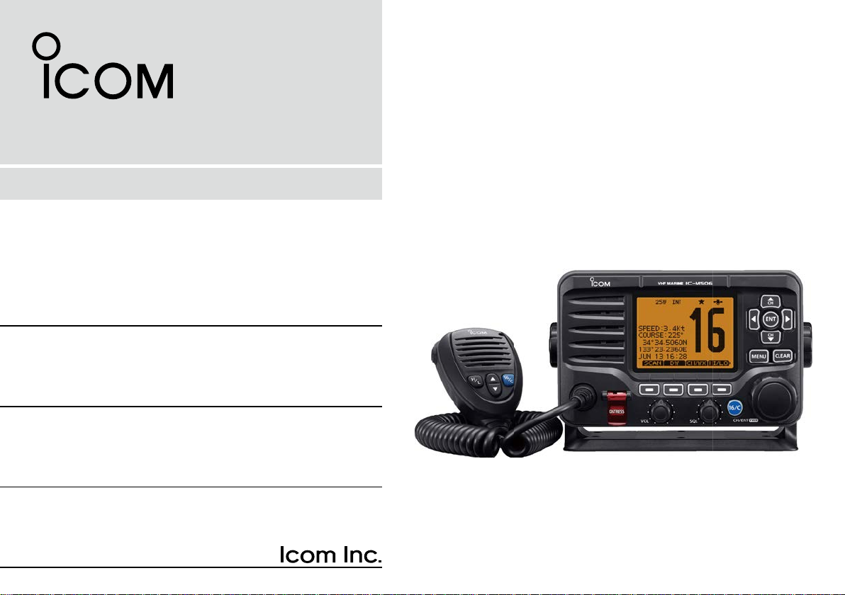
VHF MARINE TRANSCEIVERS
iM506
iM506GE
Page 2
PREFACE
IMPORTANT
Thank you for choosing this Icom product.
This product is designed and built with Icom’s state of the art
technology and craftsmanship. With proper care, this product
should provide you with years of trouble-free operation.
We appreciate you making the IC-M506/IC-M506GE your
transceiver of choice, and hope you agree with Icom’s philosophy of “technology first.” Many hours of research and development went into the de sign of your IC-M506/IC-M506GE.
D FEATURES
❍ Integrated AIS Receiver
*
❍ NMEA 2000™ Connectivity *
❍ 2 minutes Last Call Voice Recording
❍ Superb Active Noise Cancelling
*Depends on transceiver version.
CLEAN THE TRANSCEIVER AND MICROPHONE THOROUGHLY WITH FRESH WATER after exposure to water
including salt, otherwise, the keys and switch may become
inoperable due to salt crystallization.
i
READ ALL INSTRUCTIONS carefully and completely
before using the transceiver.
SAVE THIS INSTRUCTION MANUAL — This in-
struction manual contains important operating instructions
for the IC-M506/IC-M506GE.
EXPLICIT DEFINITIONS
WORD DEFINITION
RWARNING!
CAUTION
NOTE
Icom is not responsible for the destruction or damage to the
Icom transceiver, if the malfunction is because of:
• Force majeure, including, but not limited to, fires, earthquakes,
storms, floods, lightning, other natural disasters, disturbances,
riots, war, or radioactive contamination.
• The use of Icom transceivers with any equipment that is not
manufactured or approved by Icom.
Personal injury, fire hazard or electric
shock may occur.
Equipment damage may occur.
If disregarded, inconvenience only. No risk
of personal injury, fire or electric shock.
Page 3

IN CASE OF EMERGENCY
INSTALLATION NOTE
If your vessel requires assistance, contact other vessels and
the Coast Guard by sending a Distress call on Channel 16.
USING CHANNEL 16
DISTRESS CALL PROCEDURE
1. “MAYDAY MAYDAY MAYDAY.”
2. “THIS IS ...............” (name of vessel).
3. Say your call sign or other description of the v essel (AND
9 digit DSC ID if you have one).
4. “LOCATED AT ...............” (your position).
5. State the nature of the distress and assistance required.
6. Give any other information which might facilitate the rescue.
Or, transmit your Distress call using digital selective calling
on Channel 70.
USING DIGITAL SELECTIVE CALLING (Ch 70)
DISTRESS CALL PROCEDURE
1. While lifting up the key cover, hold down [DISTRESS]
for 3 seconds until you hear 3 short beeps and then one
long beep.
2. Wait for an acknowledgment on Channel 70 from a coast
station.
• After the acknowledgement is received, Channel 16 is auto-
matically selected.
3. Hold down [PTT], then transmit the appropriate information as listed to the left.
Installation:
The installation of this equipment should be made in such a
manner as to respect the EC recommended electromagnetic
field exposure limits. (1999/519/EC)
The maximum RF power available from this device is 25
watts. The antenna should be installed as high as possible
for maximum efficiency and the installation height should be
at least 1.4 meters above any accessib le position. In the case
where an antenna cannot be installed at a reasonable height,
then the transmitter should neither be continuously operated
for long periods if any person is within a distance of 1.4 meters of the antenna, nor operated at all if any person is touching the antenna.
It is recommended that antenna of a maximum gain of 3 dB
are used. If higher gain antenna are required then please
contact your Icom distributor for revised installation recommendations.
Operation:
The exposure to RF electromagnetic field is only applicable
when this device is transmitting. This exposure is naturally
reduced due to the nature of alternating periods of receiving
and transmitting. Keep your transmissions to the minimum
necessary.
ii
Page 4

PRECAUTIONS
RWARNING! NEVER
outlet. This could cause a fire, electric shock and damage the
transceiver.
connect the transceiver to an AC
RWARNING! NEVER connect the tr ansceiver to a po w-
er source of more than 16 V DC, such as a 24 V battery. This
could cause a fire and damage the transceiver.
RWARNING! NEVER reverse the DC power cable po-
larity when connecting to a power source. This could cause a
fire, electric shock and damage the transceiver.
RWARNING! NEVER remove the fuse holders on the
DC cable. This could cause a fire, electric shock and damage
the transceiver.
RWARNING! NEVER operate the transceiver during a
lightning storm. It may result in an electric shock, cause a
fire or damage the transceiver. Always disconnect the power
source and antenna before a storm.
CAUTION:
operation of the vessel may be hindered or where it could
cause bodily injury.
NEVER
place the transceiver where normal
KEEP the transceiver and microphone at least 1 m away
from the vessel’s magnetic navigation compass.
DO NOT place or leave the transceiver in areas with tem-
peratures below –20°C or above +60°C or, in areas subject to
intense sunlight, such as the dashboard.
iii
DO NOT use harsh solvents such as benzine or alcohol to
clean the transceiver, as they will damage the transceiver’s
surfaces. If the transceiver becomes dusty or dirty, wipe it
clean with a soft, dry cloth.
DO NOT disassemble or modify the tr ansceiver f or an y rea-
son.
BE CAREFUL! The transceiver rear panel will become
hot when operating continuously for long periods of time.
Place the transceiver in a secure place to avoid inadvertent
use by children.
BE CAREFUL! The transceiver meet IPX8 requirements
and the optional HM-195
quirements for waterproof protection. However, once the
transceiver has been dropped, waterproof protection cannot
be guaranteed because of possible damage to the transceiver’s case or the waterproof seal.
* Except for the DC power connector, NMEA In/Out leads and AF
Out leads.
Icom, Icom Inc. and Icom logo are registered trademarks of Icom Incorporated
(Japan) in Japan, the United States, the United Kingdom, Germany, France,
Spain, Russia, Australia, New Zealand, and/or other countries.
COMMANDMIC is a registered trademark of Icom Incorporated (Japan) in Japan and the United States.
commandmicIV™ meet IPX7 re-
Page 5
ABOUT CE AND DOC
Hereby , Icom Inc. declares that the v ersions of
IC-M506GE which have the “CE” symbol on
the product, comply with the essential re-
quirements of the Radio Equipment Directive,
2014/53/EU, and the restriction of the use of certain hazardous substances in electrical and electronic equipment Directive, 2011/65/EU . The full te xt of the EU declaration of conformity is available at the following internet address:
http://www.icom.co.jp/world/support/
DISPOSAL
The crossed-out wheeled-bin symbol on your
product, literature, or packaging reminds you
that in the European Union, all electrical and
electronic products, batteries, and accumulators
(rechargeable batteries) must be taken to des-
ignated collection locations at the end of their
working life. Do not dispose of these products as unsorted
municipal waste. Dispose of them according to the laws in
your area.
1
2
3
4
5
6
7
8
9
10
11
12
13
14
15
16
iv
Page 6

TABLE OF CONTENTS
PREFACE ................................................i
IMPORTANT ...........................................i
EXPLICIT DEFINITIONS .........................i
IN CASE OF EMERGENCY ....................ii
INSTALLATION NOTE ............................ii
PRECAUTIONS .......................................iii
ABOUT CE AND DOC .............................iv
DISPOSAL ...............................................iv
1 OPERATING RULES ..........................1
2 PANEL DESCRIPTION ...................2–6
■ Front panel ......................................2
■ Function display ..............................4
■ Speaker Microphone .......................6
■ Softkey function ..............................6
3 PREPARATION ..............................7–8
■ MMSI code entry .............................7
■ ATIS code entry ..............................8
4 BASIC OPERATION .....................9–14
■ Channel selection ...........................9
■ Receiving and transmitting ............11
■ Call channel entry .........................12
■ Channel name entry .....................12
■ Microphone Lock function .............13
■ Adjusting the Backlight level .........14
■
AquaQuake water draining function
5 SCAN OPERATION ....................15–16
■ Scan types ....................................15
■ Setting Favorite channels .............16
■ Starting a scan ..............................16
...14
6 DUALWATCH/TRI-WATCH ..............17
■ Description ....................................17
■ Operation ......................................17
7 DSC OPERATION ......................18–66
■ DSC address ID ...........................18
■ Position and time programming
■ Distress call ...................................22
■ Transmitting DSC calls .................27
■ Receiving DSC calls .....................46
■ Received Call log ..........................58
■ Transmitted Call log ......................60
■ DSC Settings ................................61
■ Making an Individual call using
an AIS transponder .......................65
8 OTHER FUNCTIONS ..................67–71
■ Intercom operation ....................... 67
■ RX Hailer function ........................ 68
■ Hailer operation ............................ 68
■ Horn function ................................ 69
■ Voice scrambler operation .......... 71
■ Voice recorder function ................ 71
9 AIS RECEIVER
(Depending on versions) ..........72–81
■ About AIS ......................................72
■ AIS Classes ..................................72
■ Function display ............................73
■ About the detail screen .................76
■ AIS Settings ..................................79
.......21
10 NMEA 2000 CONNECTION
(Depending on versions) ..........82–83
■ Description ....................................82
11 MENU SCREEN OPERATION ...84–93
■ Menu screen operation .................84
■ Menu screen items ........................85
■ Configuration items .......................86
■ Radio Settings items .....................90
12 CONNECTIONS AND
MAINTENANCE ........................94–102
■ Connections ..................................94
■ Antenna .........................................96
■ Fuse replacement .........................96
■ Cleaning ........................................96
■ Supplied accessories ....................96
■ Mounting the transceiver ...............97
■ MB-75/MB-132 installation ............98
■ Microphone installation ...............100
13 SPECIFICATIONS
AND OPTIONS .......................103–105
■ Specifications ..............................103
■ Options ........................................104
14 CHANNEL LIST ......................106–108
15 TEMPLATE .....................................109
16 TROUBLESHOOTING ....................111
v
Page 7

OPERATING RULES
1
D Priorities
• Read all rules and regulations per taining to call priorities,
and keep an up-to-date copy handy. Safety and distress
calls take priority over all others.
• You must monitor Channel 16 when you are not operating
on another channel.
• False or fraudulent distress calls are prohibited under law.
D Privacy
• Information overheard, but not intended for you, cannot lawfully be used in any way.
• Indecent or profane language is prohibited.
D Radio licenses
(1) SHIP STATION LICENSE
You may require a current radio station license before using
the transceiver . It is unla wful to operate a ship station which is
not licensed, but required to be.
If required, contact your dealer or the appropriate government agency for a Ship-Radiotelephone license application.
This government-issued license states the call sign which is
your craft’s identification for radio purposes.
(2) OPERATOR’S LICENSE
A Restricted Radiotelephone Operator Permit is the license
most often held by small vessel radio operators when a r adio
is not required for safety purposes.
If required, the Restricted Radiotelephone Operator Permit
must be posted or kept with the operator. If required, only a
licensed radio operator may operate a transceiver.
Howev er , non-licensed individuals may talk o ver a transceiv er
if a licensed operator starts, supervises, ends the call and
makes the necessary log entries.
A current copy of the applicable government r ules and regulations is only required to be on hand for vessels in which
a radio telephone is compulsory. However, even if you are
not required to have these on hand it is your responsibility to
be thoroughly acquainted with all pertinent rules and regulations.
1
2
3
4
5
6
7
8
9
10
11
12
13
14
15
16
1
Page 8
2
i
o
!0!1
Function display (p. 4)
Speaker
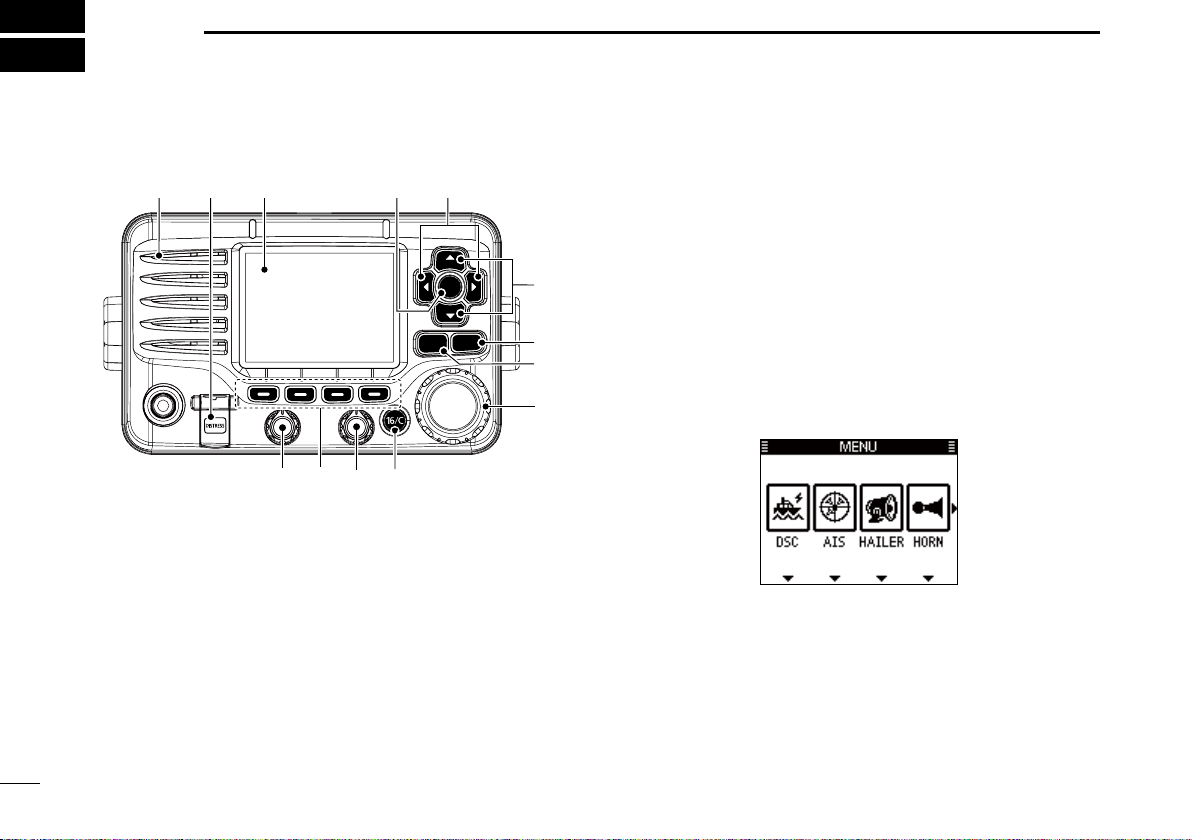
PANEL DESCRIPTION
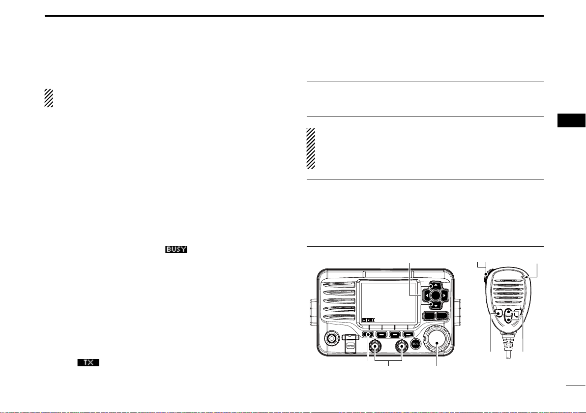
Front panel
q
q DISTRESS KEY [DISTRESS] (pp. 22, 23)
Hold down for 3 seconds to transmit a Distress call.
w ENTER KEY [ENT]
Push to set the input data, selected item, and so on.
e LEFT AND RIGHT KEYS [Ω]/[≈]
2
Push to switch to the previous or next key function that
is assigned to the softkeys. (p. 7)
Push to select a desired character or number in the
table while in the channel name, position, MMSI code,
ATIS code programming mode, and so on. (pp. 8, 12,
21)
w
r
UP AND DOWN/CHANNEL SELECT KEYS [∫CH]/[√CH]
e
CH
ENT
CH
CLEARMENU
r
t
y
u
Push to select the operating channels, Menu items,
Menu settings, and so on.
While scanning, push to check Favorite channels,
change the scanning direction or manually resume a
scan. (p. 16)
t CLEAR KEY [CLEAR]
Push to cancel the entered data, or to return to the previ-
ous screen.
y MENU KEY [MENU]
Push to enter or exit the Menu screen. (p. 84)
u DIAL/POWER SWITCH [PWR]
When the power is OFF, hold down for 1 second to turn
ON power.
Hold down for 1 second to turn OFF power.
Rotate to select the operating channels, Menu items,
Menu settings, and so on.
Push to set the input data, selected item, and so on.
Page 9
PANEL DESCRIPTION
2
i CHANNEL 16/CALL CHANNEL KEY [16/C]
Push to select Channel 16. (p. 9)
Hold down for 1 second to select the Call channel. (p. 9)
• The “CALL” icon appears when the Call channel is selected.
o SQUELCH DIAL
Rotate to adjust the squelch level.
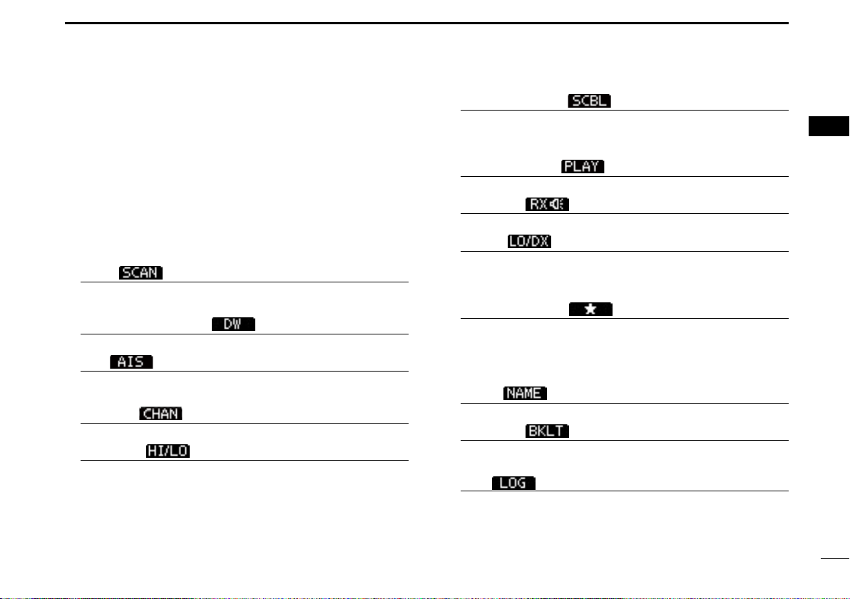
!0 SOFTKEYS
Desired functions as described below can be assigned in
the Menu screen. (p. 87)
Scan [
Push to start or stop a Normal or Priority scan.
*This key does not appear in Dutch version transceivers.
Dualwatch/Tri-watch [ ] (p. 17)
Push once to start and stop a Dualwatch or Tri-watch scan.
AIS [
Push to display the AIS plotter on the left side of the display.
*Some versions do not have an AIS receiver.
Channel [ ] (pp. 9, 11)
Push to select a regular channel.
High/Low [
Push to set the power to high or low.
• Some channels are set to only low power.
]* (p. 16)
]* (p. 73)
] (p. 11)
Voice Scrambler [ ]* (p. 71)
Push to turn the Voice Scrambler ON or OFF.
• The “SBL” icon appears when the voice scrambler is ON.
*This key appears only when the voice scrambler unit is installed.
Voice Recorder [ ] (p. 71)
Push to playback recorded voice.
RX Hailer [ ] (p. 61)
Push to turn the RX Hailer mode ON or OFF.
LO/DX [
Push to turn the Attenuator function ON or OFF.
• The “LOC” icon appears when the Attenuator function is ON.
*This key appears only for Australian version transceivers.
Favorite channel [ ] (p. 16)
Push to set or clear the displayed channel as a Fa vorite
(Tag) channel.
Hold down for 3 seconds to clear or set all Favorite
(Tag) channels in the selected channel group.
Name [
Push to enter the channel name entry mode.
Backlight [
Push to enter the LCD and key backlight brightness ad-
justment mode.
Log [
Push to enter “RCVD CALL LOG” in the DSC CALLS menu.
]*
] (p. 12)
] (p. 14)
] (p. 58)
1
2
3
4
5
6
7
8
9
10
11
12
13
14
15
16
!1 VOLUME DIAL
Rotate to adjust the volume level.
3
3
Page 10
PANEL DESCRIPTION
2
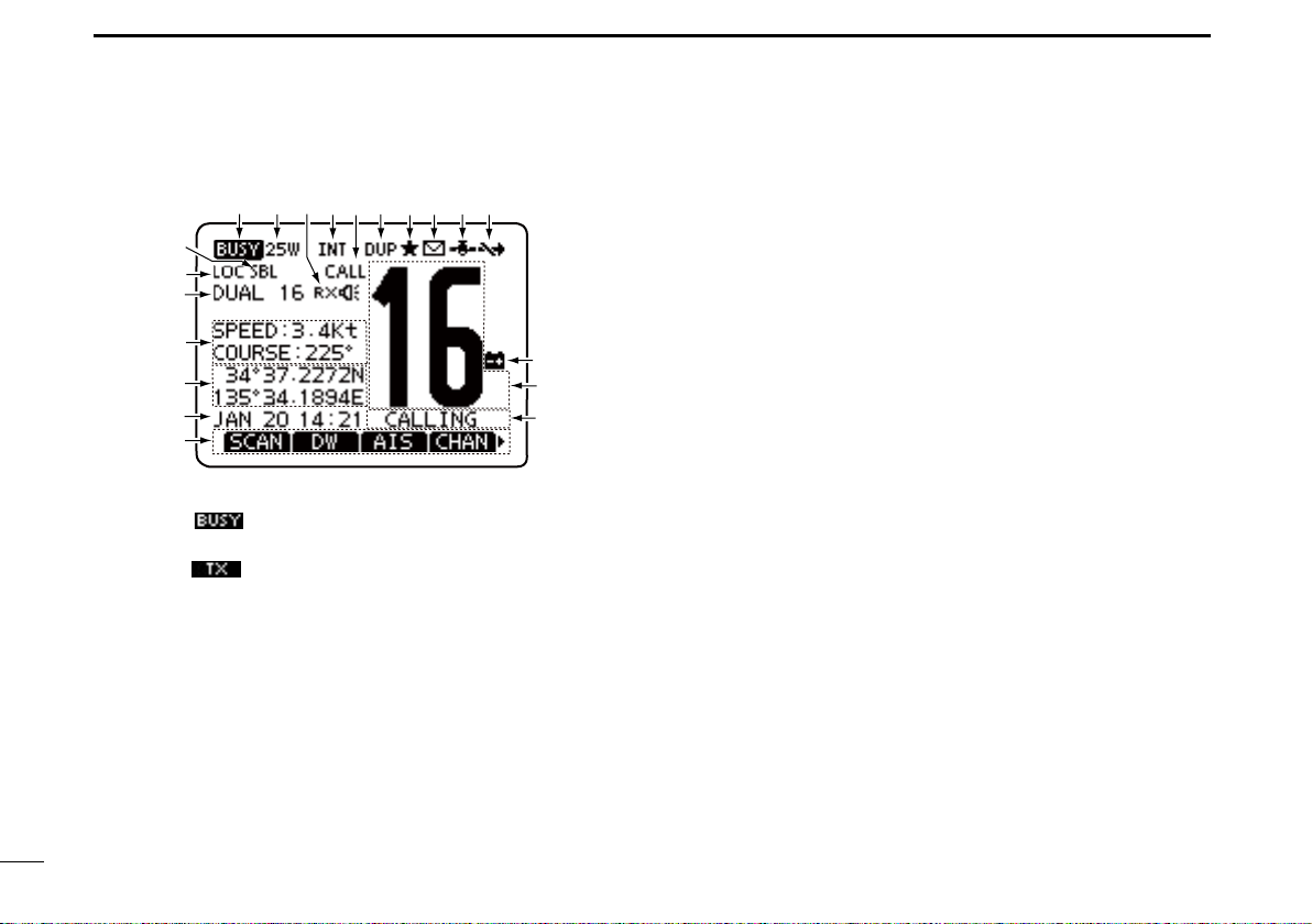
Function display
q
@0
!9
!8
!7
!6
!5
!4
q BUSY/TRANSMIT ICON (p. 11)
The “
when the squelch is open.
The “
w POWER ICON (p. 11)
The “25W” icon appears when high power is selected.
The “1W” icon appears when low power is selected.
e RX HAILER ICON (p. 68)
Appears while in the RX Hailer mode.
r CHANNEL GROUP ICON (p. 10)
Shows which channel group is selected, a USA “USA”
International “INT” ATIS “ATIS” or DSC “DSC”*, depending on the version.
*German transceiver version only
4
e
w
” icon appears when receiving a signal, or
” icon appears while transmitting.
r
t
y
u
i
o
!0
!1
!2
!3
t CALL CHANNEL ICON (p. 9)
Appears when the Call channel is selected.
y DUPLEX ICON (p. 10)
Appears when a duplex channel is selected.
u FAVORITE CHANNEL ICON (p. 16)
Appears when a Favorite (Tag) channel is selected.
i MESSAGE ICON
Blinks when there is an unread DSC message.
o GPS ICON
Stays ON when the GPS receiver is activated and v alid
position data is received.
Blinks when invalid position data is being received.
!0 SWITCH ICON (p. 62)
Appears when the “CH 16 SWITCH” in DSC Settings is set
to OFF.
!1 LOW BATTERY ICON
Blinks when the battery voltage drops to approximately
10.8 V DC or less.
!2 CHANNEL NUMBER READOUT
Displays the selected operating channel number.
• When a simplex channel is selected, “A” or “B” appears.
!3 CHANNEL NAME FIELD
The channel name appears, if entered. (p. 12)
Page 11

PANEL DESCRIPTION
2
1
!4 KEY ICON (p. 6)
Displays the assigned function of the softkeys on the front
panel.
!5 TIME ZONE INDICATOR
Displays the current time when a GPS receiver is con-
nected, or the time is manually entered.
• When the GPS current time is invalid, “??” will blink every
2 seconds instead of the current time. After 23.5 hours has
passed, “NO TIME” will appear.
• “ ??”
!6 POSITION INDICATOR
• When the GPS position is invalid, “??” ma y b link e very 2 sec-
will
blink every 2 seconds instead of the current time,
after 4 hours have passed from when the time was manually entered. The manually programmed time is held for only
23.5 hours, and after that, “NO TIME” will appear.
“LOCAL” appears when the offset time is set.
“MNL” appears when
“ UTC” appears when
tence formats are included in the GPS signal.
The date information appears when
tence formats are included in the GPS signal.
“ NO TIME” appears when no GPS receiver is connect-
ed, and no time is manually entered.
Shows the current position when a GPS receiver is
connected, or the position is manually entered.
onds instead of displaying the position. The last position is
held for only 23.5 hours, and after that, “NO POSITION” will
appear.
the time is manually entered
the GGA, GLL or GNS GPS sen-
the RMC GPS sen-
.
• “ ??” will blink every 2 seconds instead of displaying the position, after 4 hours have passed from when the position is
manually entered. The manually entered position is held for
only 23.5 hours, and after that, “NO POSITION” will appear.
“ NO POSITION” appears when no GPS receiver is
connected, and no position is manually entered.
!7 COURSE/SPEED INDICATOR
Shows the course and speed of your vessel if a GPS re-
ceiver is connected to the transceiver.
• Course and speed are displayed when the RMC GPS sentence
format is included in the GPS signal.
Course and speed are also displayed when the VTG and either
the GGA, GLL or GNS GPS sentence formats are included in the
GPS signal.
!8 SCAN INDICATOR
“ SCAN 16” appears during a Priority scan, “SCAN” ap-
pears during a Normal scan. (p. 16)
“ DUAL 16” appears during Dualwatch, “TRI 16” ap-
pears during Tri-watch. (p. 17)
!9 LOCAL ICON
Appears when the Attenuator function is turned ON.
*
This function is usable for only Australian version transceivers.
@0 VOICE SCRAMBLER ICON* (p. 71)
Appears when the Voice Scrambler function is turned ON.
* Appears only when the voice scrambler unit is installed.
2
3
4
5
6
7
8
9
10
11
12
13
14
15
16
5
Page 12
PANEL DESCRIPTION
2
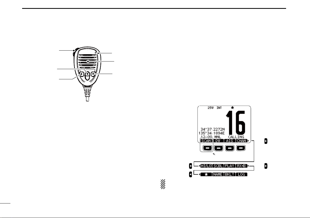
Speaker Microphone
q
w
e
q PTT SWITCH [PTT]
Hold down to transmit, release to receive. (p. 11)
w CHANNEL UP/DOWN KEYS [Y]/[Z]
Push either key to check Favorite channels, change scan-
ning direction or manually resumes a scan. (pp. 11, 16)
• You can turn OFF the FAV on MIC setting (p. 93). After that, you
can select all channels with these keys.
e TRANSMIT POWER KEY [H/L]
Push to toggle the power high or low. (p. 11)
• Some channels are set to only low power.
While holding down [H/L], turn ON the power to turn the
Microphone Lock function ON or OFF. (p. 13)
r CHANNEL 16/CALL CHANNEL KEY [16/C]
Push to select Channel 16. (p. 9)
Hold down for 1 second to select the Call channel. (p. 9)
• The “CALL” icon appears when the Call channel is selected.
6
6
Microphone
Speaker
r
Softkey function
Various functions can be assigned to the softkeys. When a
key function is assigned, the key icon is displayed above the
softkey, as shown below.
D Softkey function selection
When “Ω” or “≈” is displa yed beside the ke y icon, pushing [Ω]/
[≈] to scroll key functions that are assigned to the softkeys.
The key movement is set to “Group” in default. 4 icons move
by pushing [Ω]/[≈] once. You can set the key movement of
your choice in menu screen. (p. 87)
Push
Push this key to start
and stop scan.
PushPush
Push
The order of the key icons may differ, depending on the
transceiver version.
Page 13
PREPARATION
3
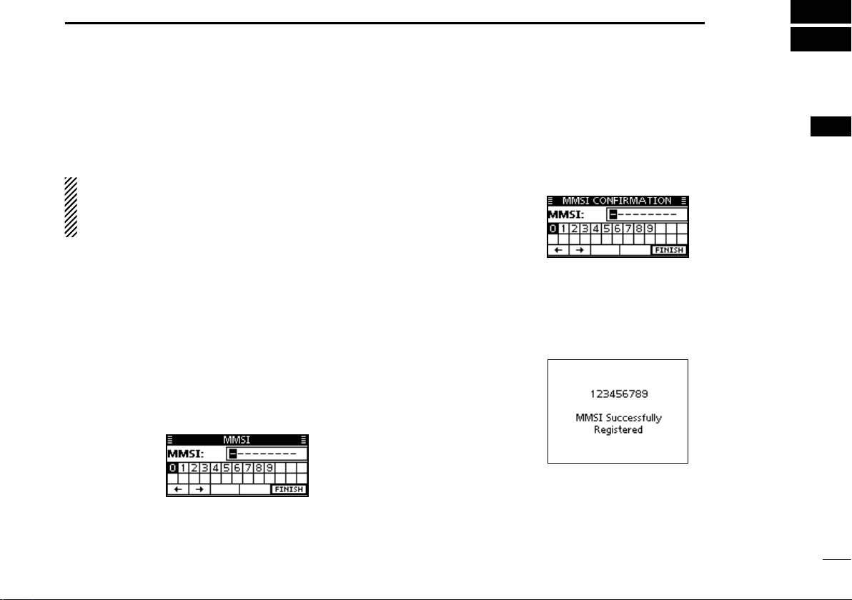
MMSI code entry
The 9 digit MMSI (Maritime Mobile Service Identity: DSC self
ID) code can be entered at power ON.
This initial code setting can be performed only once.
After being set, it can be changed by only your dealer
or distributor. If your MMSI code has already been entered, this procedure is not necessary.
q Hold down [PWR](Dial) to turn ON the power.
• Three short beeps sound, and “NO DSC MMSI” is displayed.
w Push [ENT] to start the MMSI code entry.
• Push [CLEAR] twice to cancel the entr y, and go to the normal
operating screen. In this case, the transceiver cannot make a
DSC call. To enter the MMSI code, turn OFF the power, then turn
it ON again.
e Enter your MMSI code in the following manner:
• Select a desired number using [Y]/[Z]/[Ω]/[≈].
• Push [ENT] or dial to set it.
• T o move the cursor, rotate dial or select either arrow, “←” or “→,”
then push [ENT] or dial.
r Repeat step e to enter all 9 digits.
t After entering the 9 digit code, “FINISH” is automatically
selected, and then push [ENT] or dial to set it.
y The “MMSI CONFIRMATION” screen is displayed.
u Enter your MMSI code again for confirmation.
• Enter in the same manner as steps e through t.
i When your MMSI code entry is successfully completed,
the screen as shown below is briefly displayed.
• After that, the normal operating screen is displayed.
The entered MMSI code can be checked in the MENU screen.
(p. 85)
1
2
3
4
5
6
7
8
9
10
11
12
13
14
15
16
7
Page 14
PREPARATION
3
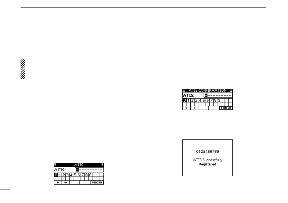
ATIS code entry (For Dutch and German version transceivers)
The 10 digit ATIS (Automatic Transmitter Identification System) code can be entered at power ON.
This initial code setting can be performed only once.
After being set, it can be changed by only your dealer
or distributor. If your ATIS code has already been entered, this procedure is not necessary.
q Push [MENU].
w Rotate dial or push [Ω]/[≈] to select the “RADIO SET” icon
and then push the softkey below the icon.
• The RADIO SETTINGS menu is displayed.
e Rotate dial or push [Y]/[Z] to select “CHAN Group,” and
then push [ENT].
r Rotate dial or push [Y]/[Z] to select “ATIS,” and then push
[ENT].
t Push [BACK] twice.
y Rotate dial or push [Ω]/[≈] to select the “ATIS” icon and
then push the softkey below the icon.
• ATIS code programming screen appears.
• Push [CLEAR] to cancel the programming, and go to the normal
operating mode. In this case, the ATIS function is disabled. To
program the ATIS code, repeat the steps q and y.
u Enter your ATIS code in the following manner:
• Select a desired number using [∫]/[√]/[Ω]/[≈].
• Push [ENT] or Dial to set it.
• T o move the cursor, rotate dial or select either arrow, “←” or “→,”
then push [ENT] or dial.
i Repeat step u to enter all 10 digits.
o After entering the 10 digit code, “FINISH” is automatically
selected, and then push [ENT] or Dial to set it.
!0 The “ATIS CONFIRMATION” screen is displayed.
!1 Enter your ATIS code again for confirmation.
• Enter in the same manner as steps u through o.
!2 When your ATIS code entry is successfully completed, the
screen as shown below is briefly displayed.
• After that, the normal operating screen is displayed.
The entered ATIS code can be checked in the MENU screen.
(p. 85)
8
Page 15
BASIC OPERATION
4
Channel selection
D Channel 16
Channel 16 is the distress and safety channel. It is used for
establishing initial contact with a station and for emergency
communications.
While standing by, you must monitor Channel 16. Channel
16 is automatically monitored during both Dualwatch and Triwatch.
Push [16/C] to select Channel 16.
Push [CHAN] to return to the screen displayed before you
selected Channel 16, or rotate dial or push [∫](CH)/[√](CH)
to select an operating channel.
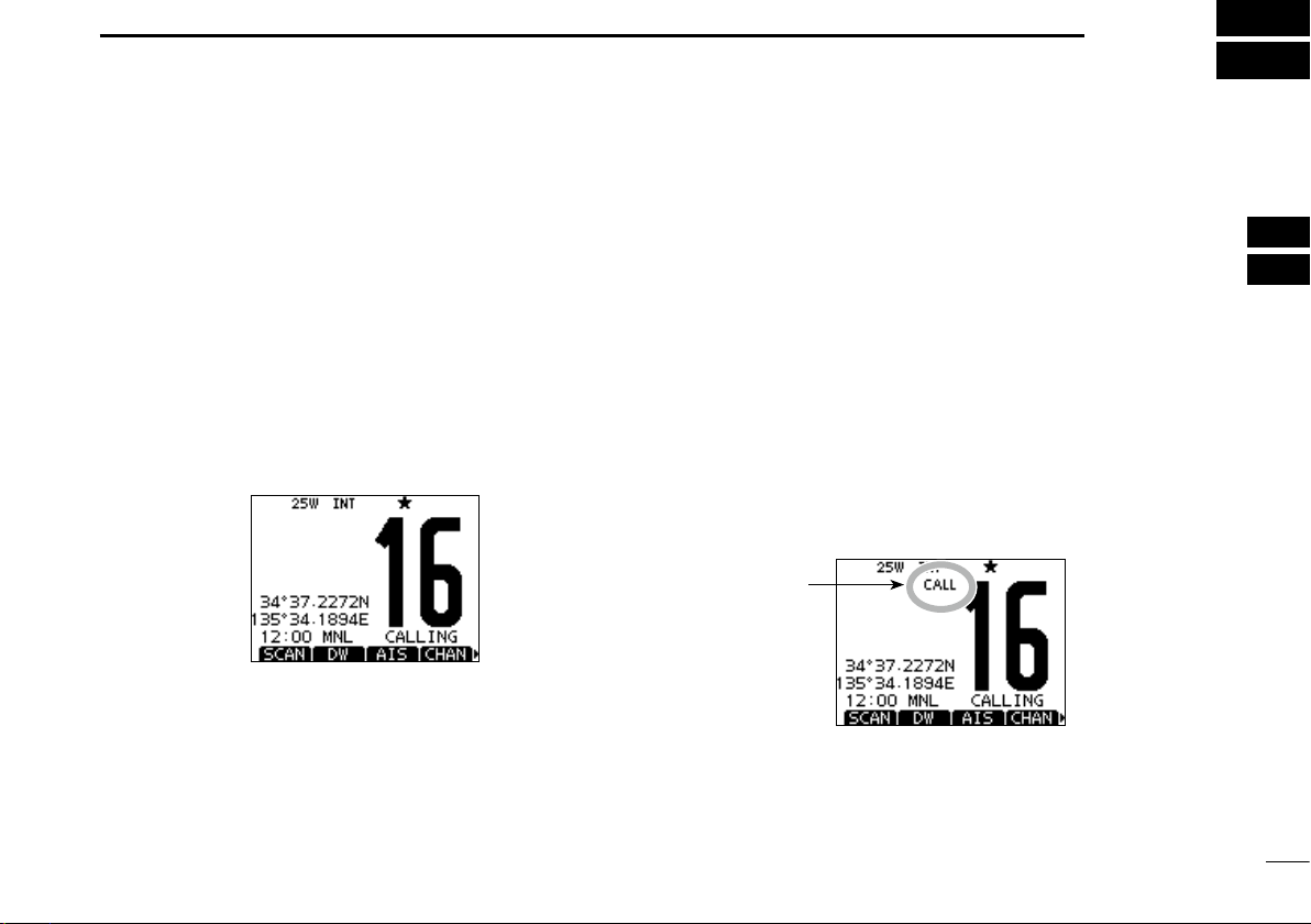
D Call channel
Each regular channel group has a separate leisure use Call
channel. The Call channels can be programmed, and are
used to store your most often used channel in each channel
group, for quick recall.
The Call channel is monitored during Tri-watch. (p. 17)
Hold down [16/C] for 1 second to select the Call channel of
the selected channel group.
• The “CALL” icon and the Call channel number appear.
• Each channel group has an independent call channel after programming. (p. 12)
Push [CHAN] to return to the screen displayed before you
selected Call channel, or rotate dial or push [∫](CH)/[√]
(CH) to select an operating channel.
Appears
1
2
3
4
5
6
7
8
9
10
11
12
13
14
15
16
9
Page 16
BASIC OPERATION
4
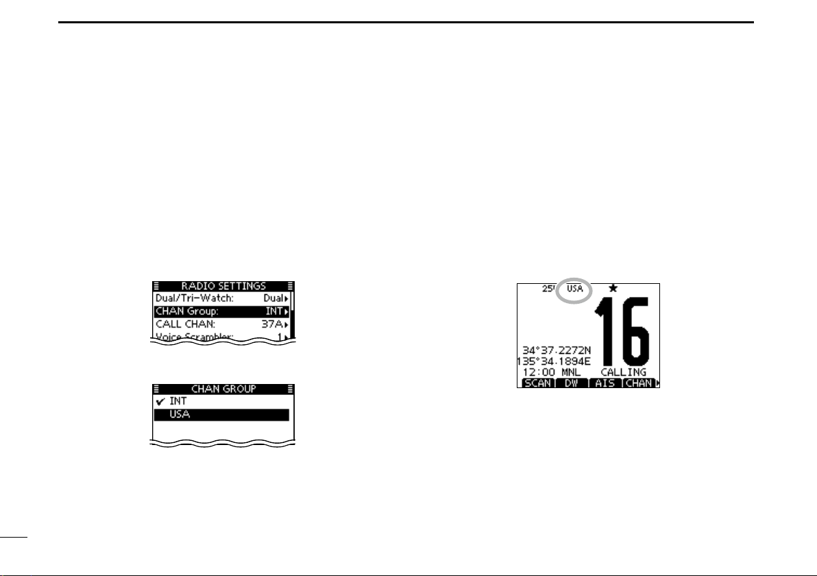
D Channel group selection
There are preset international channels for the transceiver.
Except for the Europe versions, you can select a channel
group suitable for your operating area, as described below.
q Push [MENU].
w Rotate dial or push
icon and then push the softkey below the icon.
• RADIO SETTINGS menu is displayed.
e Rotate dial or push [∫]/[√] to select “CHAN Group,” and
then push [ENT].
r Rotate dial or push [∫]/[√] to select the desired channel
group, and then push [ENT].
[Ω]/[≈] to select the “RADIO SET”
t Push [EXIT] to exit the Menu screen.
y Rotate dial or push [∫](CH)/[√](CH) to select a channel.
• Pushing [Y]/[Z] on the microphone selects only Favorite chan-
nels.
• You can turn OFF the FAV on MIC setting (p. 93). After that, you
can select all channels by using the microphone.
• The “DUP” icon appears when a duplex channel is selected.
• “A” appears when a simplex channel is selected.
Channel group icon appears
When the USA channel
group is selected.
10
Page 17
BASIC OPERATION
Microphone
uy
q
w
4
Receiving and transmitting
CAUTION: Transmitting without an antenna will damage
the transceiver.
q Hold down [PWR](Dial) to turn ON the power.
w Set the audio and squelch levels. (p. 3)
First, open the squelch. Then, adjust the audio output
level. After that, adjust the squelch level until the noise
just disappears.
e Change the channel group. (p. 10)
r Rotate dial or push [∫](CH)/[√](CH) to select a channel.
(pp. 9, 10)
• Pushing [Y]/[Z] on the microphone selects only Favorite chan-
nels.
• You can turn OFF the FAV on MIC setting (p. 93). After that, you
can select all channels using the microphone.
• When receiving a signal, the “ ” icon appears and audio is
heard.
• Further adjustment of the volume level may be necessary.
t Push [HI/LO] to select the output power, if necessary.
• The “25W” icon appears when high power is selected, and the
“1W” icon appears when low power is selected.
• Choose low power for short range communications, choose high
power for longer distance communications.
• Some channels are for only low power.
y Hold down [PTT] to transmit, then speak at your normal
voice level.
• The “ ” icon appears.
• Channel 70 cannot be used for transmission other than DSC.
u Release [PTT] to receive.
Information
The Noise Cancel function reduces random noise components
in the transmit and/or receive signal. See page
IMPORTANT: To maximize the readability of your transmitted signal, pause a few seconds after pushing [PTT], hold
the microphone 5 to 10 cm from your mouth and speak at
your normal voice level.
NOTE for the TOT (Time-out Timer) function
The TOT function inhibits continuous transmission beyond a
preset time period after the transmission starts.
A beep sounds 10 seconds before transmission is cutoff to
indicate the transmission will be shut down, and “T O T” appears
in the channel name field.
r
CH
ENT
CH
CLEARMENU
t
92
for details.
rt
2
3
4
5
6
7
8
9
10
11
12
13
14
15
16
11
Page 18
BASIC OPERATION
4
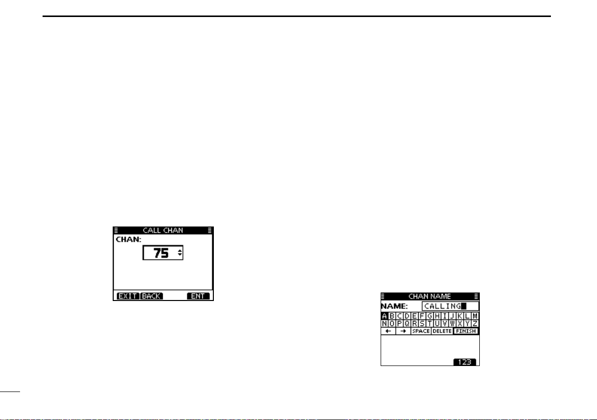
Call channel entry
You can enter the Call channel with your most often-used
channel in each channel group for quick recall.
q Select the desired channel group (INT, USA, CAN or A TIS)
to be entered. (p. 10)
w Push [MENU].
e Rotate dial or push [Ω]/[≈] to select the “RADIO SET” icon
and then push the softkey below the icon.
• RADIO SETTINGS menu is displayed.
r Rotate dial or push [∫]/[√] to select “CALL CHAN,” and
then push [ENT].
t Rotate dial or push [∫](CH)/[√](CH) to select a channel.
y Push [ENT] to save the channel as the Call channel.
• Push [BACK] to cancel and return to the previous screen.
u Push [EXIT] to exit the Menu screen.
Channel name entry
Each channel can be assigned a unique alphanumeric ID of
up to 10 characters.
Capital letters, 0 to 9, some symbols (! " # $ % & ' ( ) * + , – .
/ [ \ ] ^ _ : ; < = > ?) and a space can be input.
q Rotate dial or push [∫](CH)/[√](CH) to select a channel.
• First, cancel the Dualwatch, Tri-watch or Scan function, if activated.
w Push [NAME] to open the channel name entry screen.
• A cursor is displayed on the first character.
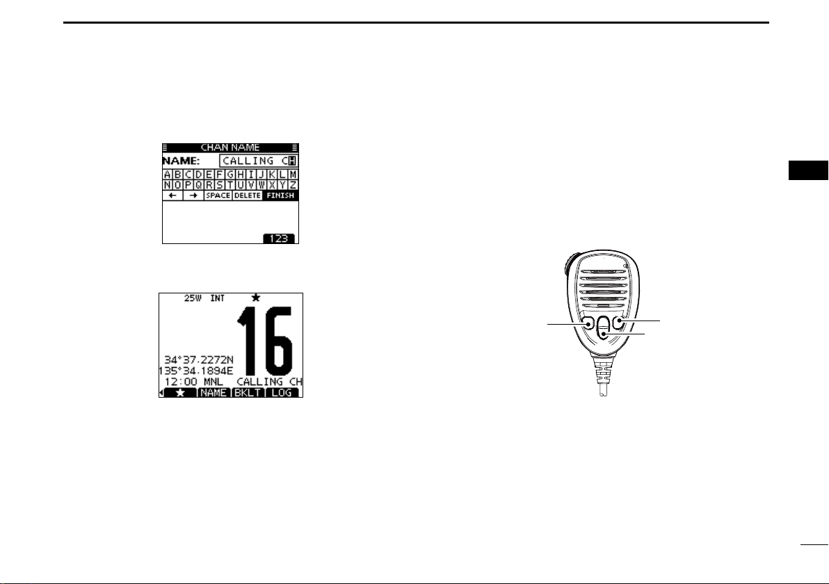
e Enter the desired channel name in the following manner:
• Select a desired character using [∫]/[√]/[Ω]/[≈].
• Push [ENT] or dial to set it.
• T o move the cursor, rotate dial or select either arrow, “←” or “→,”
then push [ENT] or dial.
• Push [123], [!$?] or [ABC] to select a character group.
• Select “SPACE,” then push [ENT] to enter a space.
• Select “DELETE,” then push [ENT] to delete a character.
• Push [CLEAR] to cancel and return to the previous screen.
12
Page 19
BASIC OPERATION
4
r Repeat step e to enter all characters.
t Push [Ω]/[≈]/[∫]/[√] to select “FINISH, ” then push [ENT] to
set the name and return to the previous screen.
Microphone Lock function
The Microphone Lock function electrically locks [∫], [√],
[16/C] and the [H/L] keys on the supplied microphone. This
prevents accidental channel changes or function access.
While holding down [H/L] on the microphone, hold down
[PWR](Dial) to turn ON the transceiver and turn the Microphone Lock function ON or OFF.
[H/L]
[16/C]
[Y]/[Z]
1
2
3
4
5
6
7
8
9
10
11
12
13
14
15
16
13
13
Page 20
BASIC OPERATION
4
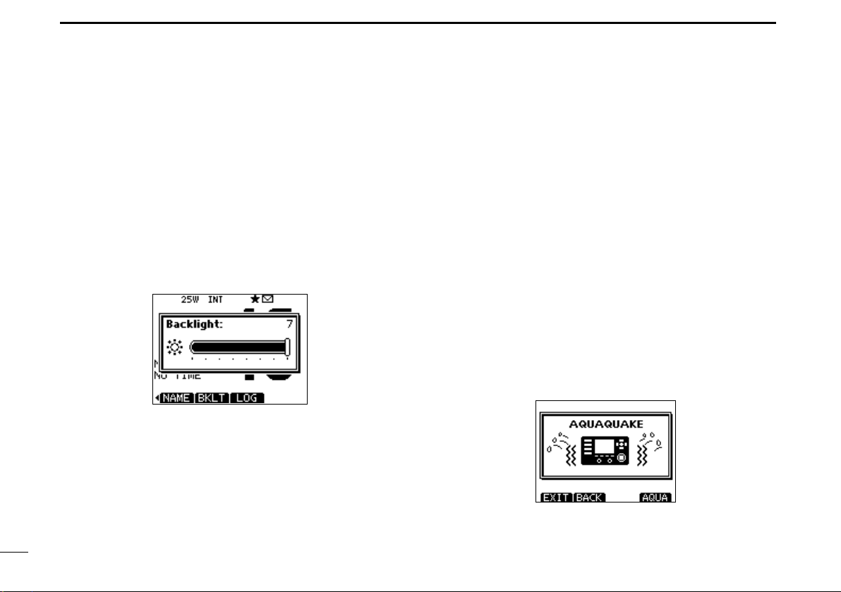
Adjusting the Backlight level
The function display and keys can be backlit for better visibility under low light conditions.
The backlight is adjustable in 7 levels, and OFF.
Depending on the presetting, the adjustment method differs,
as described below.
Push [BKLT] to show the backlight adjustment screen. Ro-
tate dial or push [∫]/[√]/[Ω]/[≈]
the LCD and key backlight, and then, push [ENT].
• If no key operation is performed for about 5 seconds, the transceiver
sets the selected backlight level, and returns to the normal mode.
to adjust the brightness of
AquaQuake water draining
function
The AquaQuake water draining function clears water away
from the speaker grill. Without this function, water may muffle
the sound coming from the speaker. A buzzing sound is heard
when this function is activated.
q Push [MENU].
w Rotate dial or push [Ω]/[≈] to select the “AQUA QUAKE,”
icon and then push the softkey below the icon.
• AQUAQUAKE screen is displayed.
While holding down [AQUA], the AquaQuake function is
activated to clear water away from the speaker grill.
• While holding down [AQUA], a low buzzing sounds to drain water, regardless of the volume level setting.
• The transceiver keys, except [DISTRESS], are disabled while
the AquaQuake function is activated.
When the AquaQuake function is activated.
1414
Page 21
SCAN OPERATION
5
■ Scan types
Scanning is an efficient way to locate signals quickly over a
wide frequency range. The transceiver has a Priority scan
and a Normal scan.
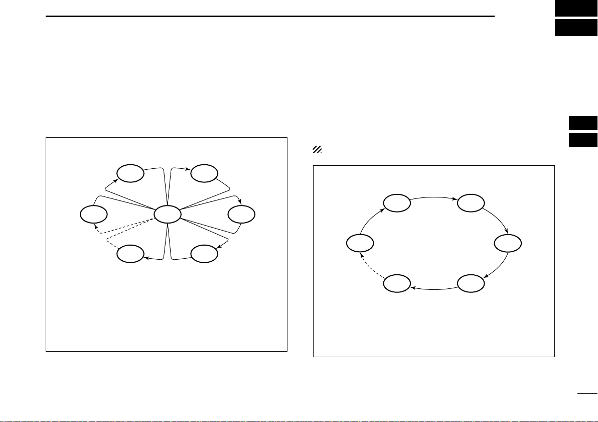
PRIORITY SCAN
CH 01
CH 88
CH 05 CH 04
The Priority scan sequentially searches through all Favorite channels while monitoring Channel 16. When a signal is
detected on Channel 16, the scan pauses until the signal
disappears. When a signal is detected on a channel other
than Channel 16, the scan becomes a Dualwatch until the
signal disappears.
CH 16
CH 02
CH 03
Set the Favorite channels (scanned channel) before scanning. Clear the Favorite channels which inconveniently stop
scanning, such as those for digital communication use. (Ref er
to the next page for details.)
Choose Priority or Normal scan in the Menu screen. (p. 90)
NORMAL SCAN
CH 01 CH 02
CH 88
CH 05 CH 04
The Normal scan, like the Priority scan, sequentially
searches through all Favorite channels. However, unlike
the Priority scan, Channel 16 is not checked unless it is set
as a Favorite channel.
CH 03
1
2
3
4
5
6
7
8
9
10
11
12
13
14
15
16
15
Page 22
SCAN OPERATION
5
■ Setting Favorite channels
For more efficient scanning, add desired channels as Favorite channels, or clear the Favorite on unwanted channels.
Channels that are not tagged as Favorites will be skipped
while scanning. Favorite channels can be independently assigned to each channel group (INT, USA, CAN or ATIS).
q Select the desired channel group. (p. 10)
w Select the desired channel to be set as a Favorite channel.
e Push [] to set the displayed channel as a Favorite channel.
• The “” icon appears on the display.
r To cancel the Favorite channel setting, repeat step e.
• The “” icon disappears.
✓ Clearing (or setting) all Favorite channels
Hold down [] for 3 seconds (until a long beep changes to
2 short beeps) to clear all Favorite channel settings in the
selected channel group.
• Repeat above procedure to set all channels as Favorite channels.
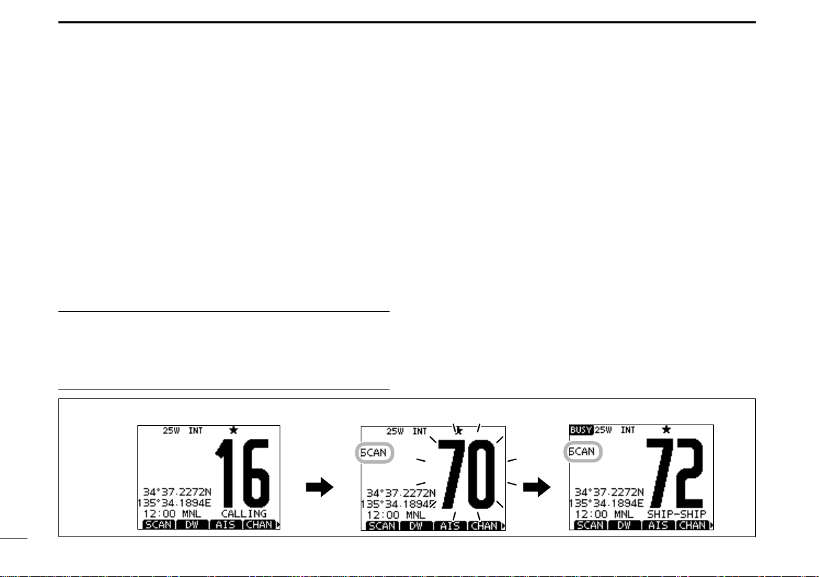
[Example]: Starting a Normal scan.
Push
[SCAN]
■ Starting a scan
First, set the scan type (Priority or Normal scan) and scan
resume timer in the Menu screen. (p. 90)
q Select the desired channel group. (p. 10)
w Set the Favorite channels, as described to the left.
e Make sure the squelch is closed to start a scan.
r Push [SCAN] to start a Priority or Normal scan.
• “ SCAN 16” appears during a Priority scan; “SCAN” appears dur-
ing a Normal scan.
• When a signal is detected, the scan pauses until the signal disappears, or resumes after pausing 5 seconds, depending on the
setting. (Channel 16 is still monitored during a Priority scan.)
• Push [Y]/[Z] on either transceiver or microphone, to check the
scanning Favorite channels, change the scanning direction or
manually resume the scan.
• A beep tone sounds and “16” blinks when a signal is received on
Channel 16 during a Priority scan.
t To stop the scan, push [CLEAR] or repeat step r.
Scan starts. When a signal is received.
16
Page 23
DUALWATCH/TRI-WATCH
6
■ Description
Dualwatch monitors Channel 16 while you are receiving
on another channel; Tri-watch monitors Channel 16 and the
Call channel while receiving another channel. Dualw atch and
Tri-watch are convenient for monitoring Channel 16 when y ou
are operating on another channel.
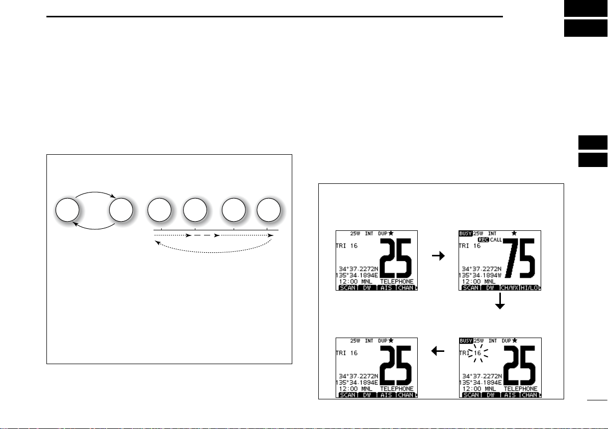
DUALWATCH/TRI-WATCH SIMULATION
Call channel
Ch 16
Dualwatch
• If a signal is received on Channel 16, Dualwatch and Triwatch pause on Channel 16 until the signal disappears.
• If a signal is received on the Call channel during Tri-watch,
Tri-watch becomes Dualwatch until the signal disappears.
• T o tr ansmit on the selected channel during a Dualwatch or
Tri-watch, hold down [PTT].
Ch 88
Ch 88
Ch 16
Ch 88
Tri-watch
Ch 75
■ Operation
q Select Dualwatch or Tri-watch in the Menu screen. (p. 90)
w Rotate dial or push [Y](CH)/[Z](CH) to select the desired
operating channel.
e Push [DW] to start a Dualwatch or Tri-watch scan.
• “ DUAL 16” appears during Dualwatch; “TRI 16” appears during
Tri-watch.
• A beep tone sounds when a signal is received on Channel 16.
r To cancel Dualwatch or Tri-watch, push [DW] again.
[Example]: Operating Tri-watch on INT Channel 25.
Tri-watch starts.
Tri-watch resumes after the
signal disappears.
Signal is received on
Call channel.
Signal received on Channel
16 takes priority.
1
2
3
4
5
6
7
8
9
10
11
12
13
14
15
16
17
Page 24
18
7
DSC OPERATION
■ DSC address ID
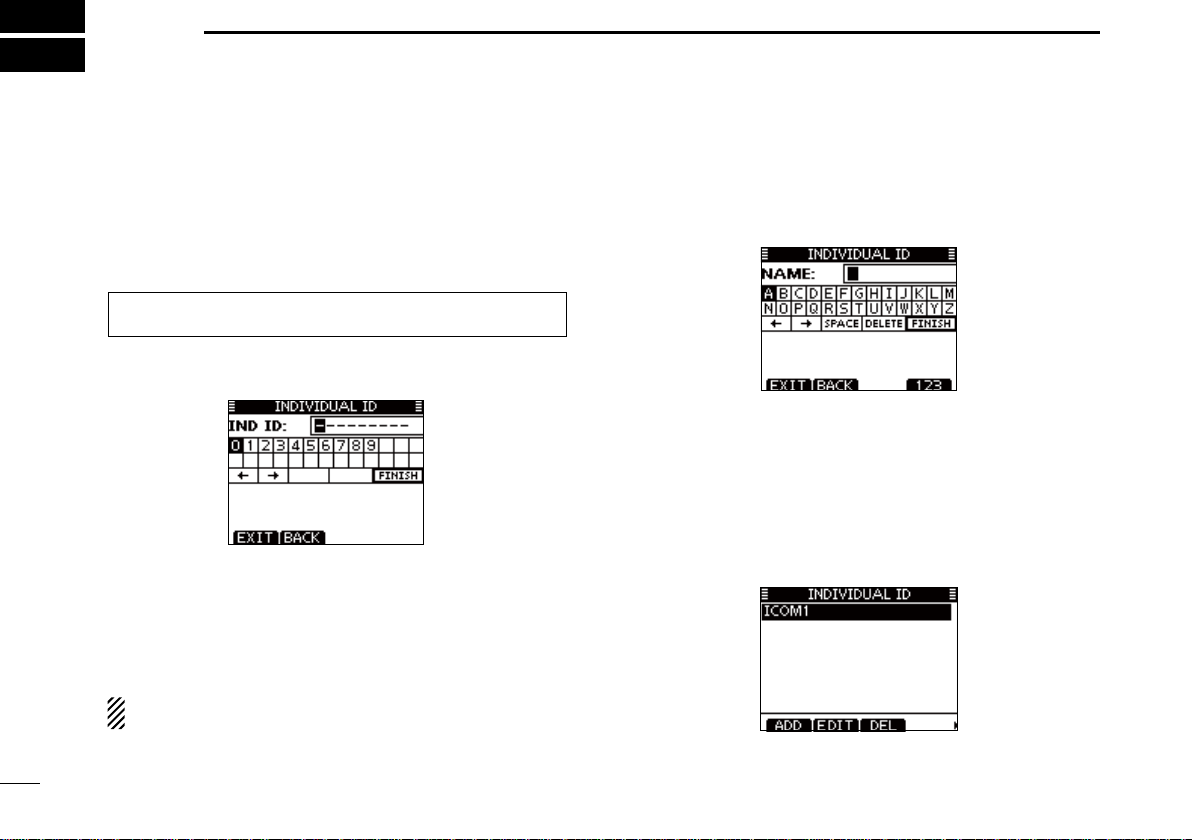
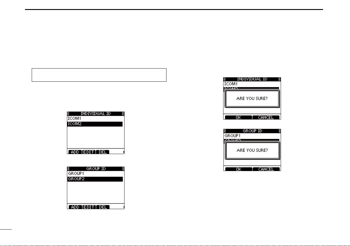
D Entering an Individual ID
A total of 100 DSC address IDs can be entered and assigned
a name of up to 10 characters.
q Select “INDIVIDUAL ID” in the DSC SETTINGS menu.
MENU ➪ DSC SET ➪
(Push [MENU]) (Select icon)
w Push [ADD].
• The “INDIVIDUAL ID” program screen is displayed.
e Enter a desired individual ID in the following way:
• Select a desired number using [Y]/[Z]/[Ω]/[≈].
• Push [ENT] or dial to set it.
• T o move the cursor, rotate dial or select either arrow, “←” or “→,”
then push [ENT] or dial.
• Push [EXIT] to return to the normal operating mode.
• Push [BACK] to return to the previous screen.
The first digit is ‘0,’ and the second digit is other than ‘0’
for a Group ID.
The first two digits are ‘0’ for any Coast station ID.
r Repeat step e to enter all 9 digits.
Individual ID
(Rotate dial, then push [ENT].)
t After entering the 9 digit code, push [ENT] or dial to set it.
• The ID name entry screen is displayed.
y Enter a desired 10 digit ID name in the following way:
• Select a desired character using [Y]/[Z]/[Ω]/[≈].
• Push [ENT] or dial to set it.
• T o move the cursor, rotate dial or select either arrow, “←” or “→,”
then push [ENT] or dial.
• Push [123], [!$?] or [ABC] to select a character group.
u After entering the ID name, select “FINISH” using [Y]/[Z]/
[Ω]/[≈], then push [ENT] to program it.
• The “INDIVIDUAL ID” list screen is displayed.
i Push [MENU] to exit the MENU screen.
Page 25
DSC OPERATION
7
1
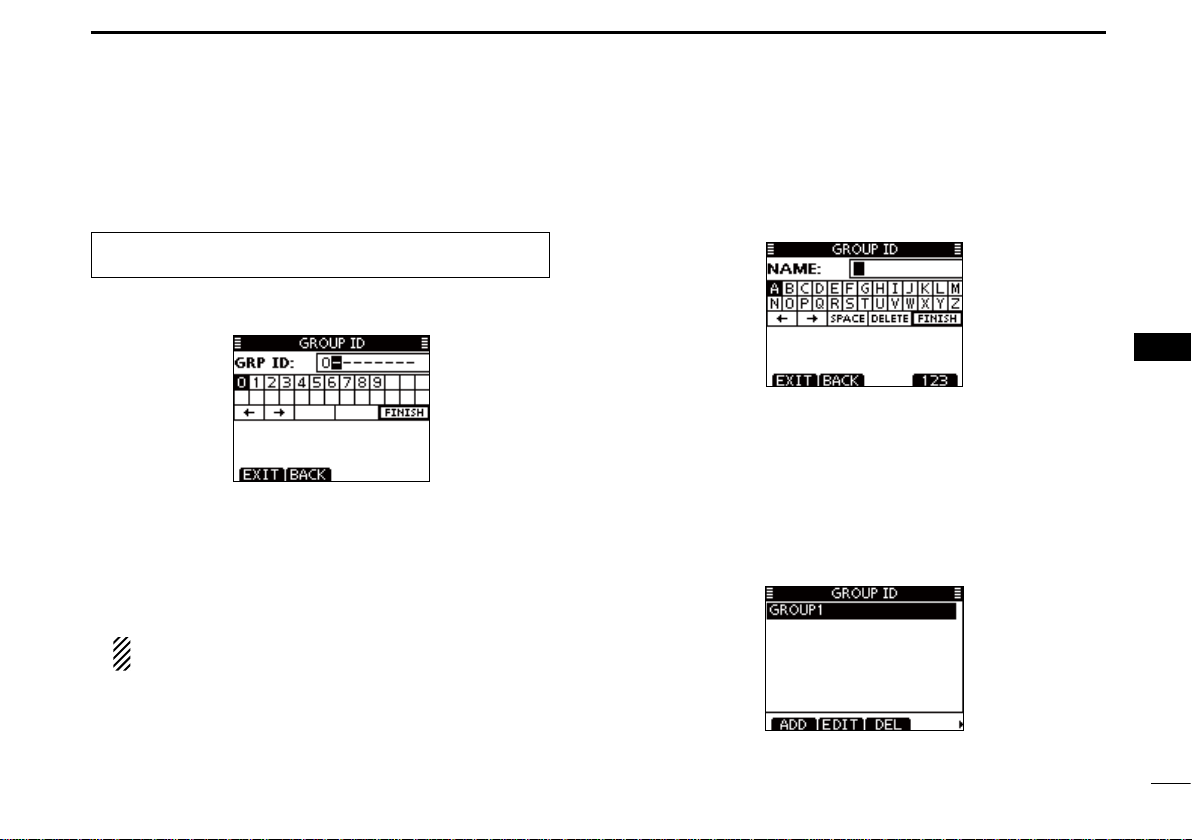
D Entering a Group ID
q Select “GROUP ID” in the DSC SETTINGS menu.
MENU ➪ DSC SET ➪
(Push [MENU]) (Select icon)
w Push [ADD].
• The “GROUP ID” program screen is displayed.
e Enter a desired group ID in the following way:
• Select a desired number using [Y]/[Z]/[Ω]/[≈].
• Push [ENT] or dial to set it.
• T o move the cursor, rotate dial or select either arrow, “←” or “→,”
then push [ENT] or dial.
• Push [EXIT] to return to the normal operating mode.
• Push [BACK] to return to the previous screen.
The first digit is fixed as ‘0’ for a Group ID.
The first two digits are ‘0’ for any Coast station ID.
r Repeat step e to enter the specific 9 digits group code.
Group ID
(Rotate dial, then push [ENT].)
t After entering the 9 digit code, push [ENT] or dial to set it.
• The Group ID name entry screen is displayed.
y Enter a desired 10 digit ID name in the following way:
• Select a desired character using [Y]/[Z]/[Ω]/[≈].
• Push [ENT] or dial to set it.
• T o move the cursor, rotate dial or select either arrow, “←” or “→,”
then push [ENT] or dial.
• Push [123], [!$?] or [ABC] to select a character group.
u After entering the ID name, select “FINISH” using [Y]/[Z]/
[Ω]/[≈], then push [ENT] or dial to program it.
• The “GROUP ID” list screen is displayed.
i Push [MENU] to exit the MENU screen.
2
3
4
5
6
7
8
9
10
11
12
13
14
15
16
19
Page 26
DSC OPERATION
7
D Deleting Individual/Group ID
q Select “INDIVIDUAL ID” or “GROUP ID” in the DSC SET-
TINGS menu.
MENU ➪ DSC SET ➪
(Push [MENU]) (Select icon)
• When no address ID is entered, “No ID” is displayed. In this case,
push [MENU] to exit the MENU screen.
w Rotate dial or push [Y]/[Z] to select a desired ID name,
then push [DEL].
Individual ID
(Rotate Dial, then push [ENT].)
/
Group ID
e Push [OK] to delete the ID, and return to the “INDIVIDUAL
ID” or “GROUP ID” list screen.
• Push [CANCEL] to cancel it.
r Push [MENU] to exit the MENU screen.
20
Page 27
DSC OPERATION
7
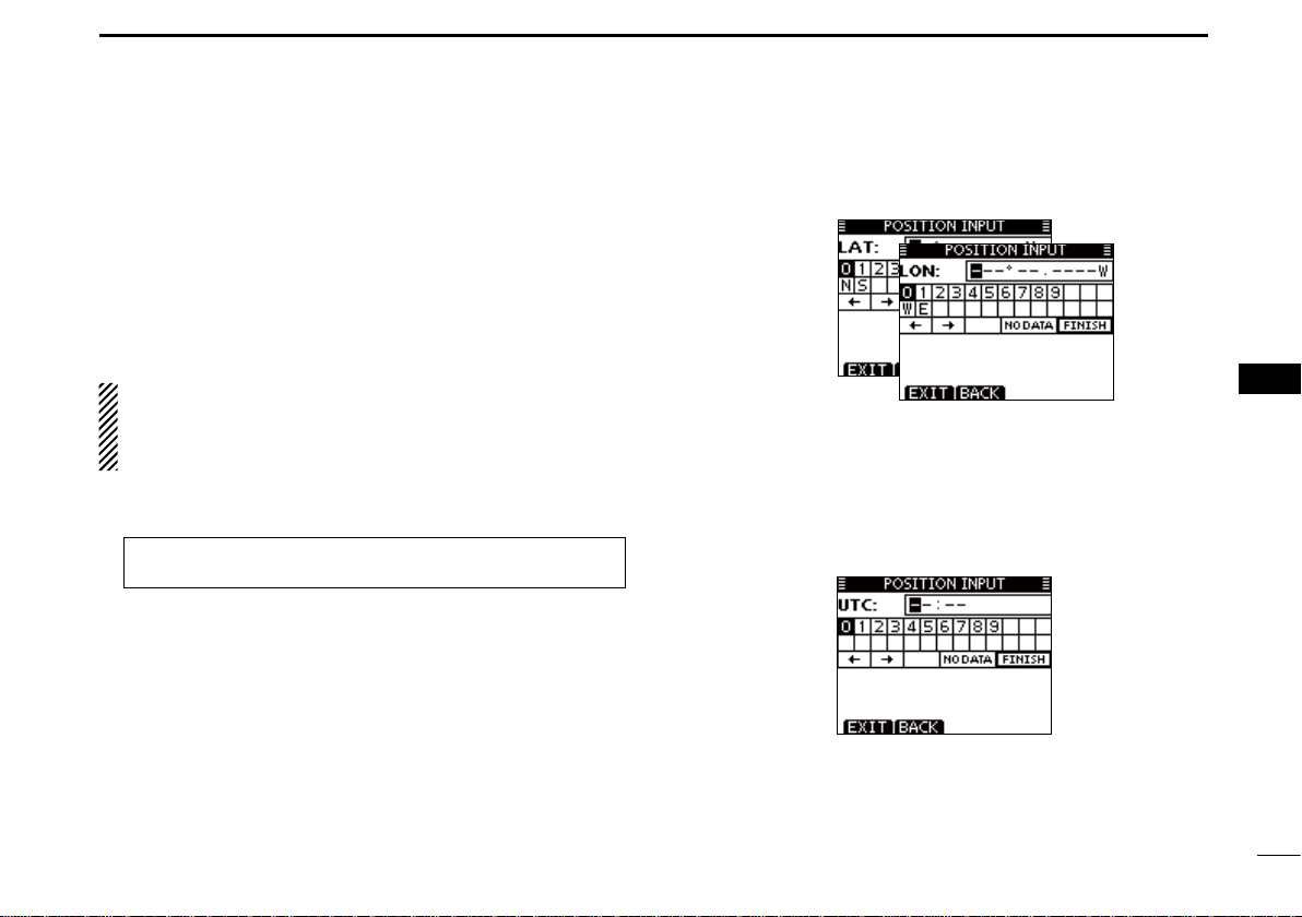
■ Position and time entry
A Distress call should include the ship’s position and time.
If no GPS is connected, your position and UTC (Universal
Time Coordinated) time should be manually entered. They
are automatically included when a GPS receiver compatible
with the NMEA 0183 (ver . 2.0 or later) or NMEA 2000* format
is connected.
* Some versions do not have a NMEA 2000 connector.
• Manual entry is disabled when a GPS receiver is connected.
• Manually entered position and time will be held for only
23.5 hours.
q Select “POSITION INPUT” in the DSC SETTINGS menu.
w Edit your latitude and longitude position using dial, and
MENU ➪ DSC SET ➪ Position Input
(Push [MENU]) (Select icon)
[Y]/[Z]/[Ω]/[≈].
• Select a desired number using [Y]/[Z]/[Ω]/[≈].
• Push [ENT] or dial to set it.
• T o move the cursor, rotate dial or select either arrow, “←” or “→,”
then push [ENT] or dial.
• Select N (North latitude) or S (South latitude) when the cursor is
on the ‘N’ or ‘S’ position.
• Select W (West longitude) or E (East longitude) when the cursor
is on the ‘W’ or ‘E’ position.
(Rotate dial, then push [ENT].)
e After entering the position, push [ENT] to program it.
r The UTC time entr y screen is displayed, enter the UTC
time in the following way:
• Select a desired number using [Y]/[Z]/[Ω]/[≈].
• Push [ENT] or dial to set it.
• T o move the cursor, rotate dial or select either arrow, “←” or “→,”
then push [ENT] or dial.
t Push [ENT] or dial to set your position and time.
• Return to the “DSC SETTINGS” screen.
1
2
3
4
5
6
7
8
9
10
11
12
13
14
15
16
21
Page 28
DSC OPERATION
7
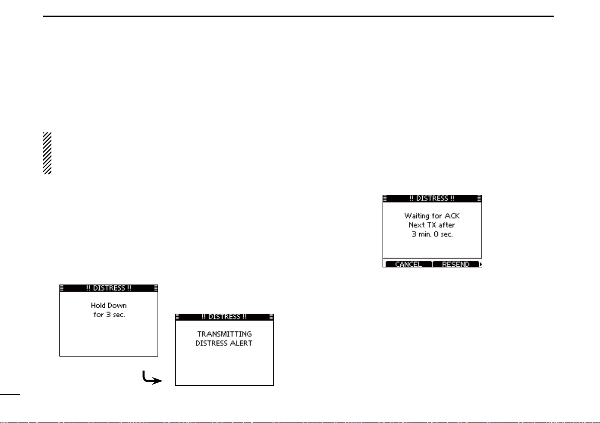
■ Distress call
A Distress call should be transmitted if, in the opinion of the
Master, the ship or a person is in distress and requires immediate assistance.
NEVER MAKE A DISTRESS CALL IF YOUR SHIP OR A
PERSON IS NOT IN AN EMERGENCY. A DISTRESS
CALL SHOULD BE MADE ONLY WHEN IMMEDIATE
HELP IS NEEDED.
D Simple call
q While lifting up the key cov er, hold down [DISTRESS] for 3
seconds to transmit the Distress alert.
• While holding down [DISTRESS], count down beeps sound and
both the key and display backlighting blink.
• DSC channel (Channel 70) is automatically selected and the
Distress alert is transmitted.
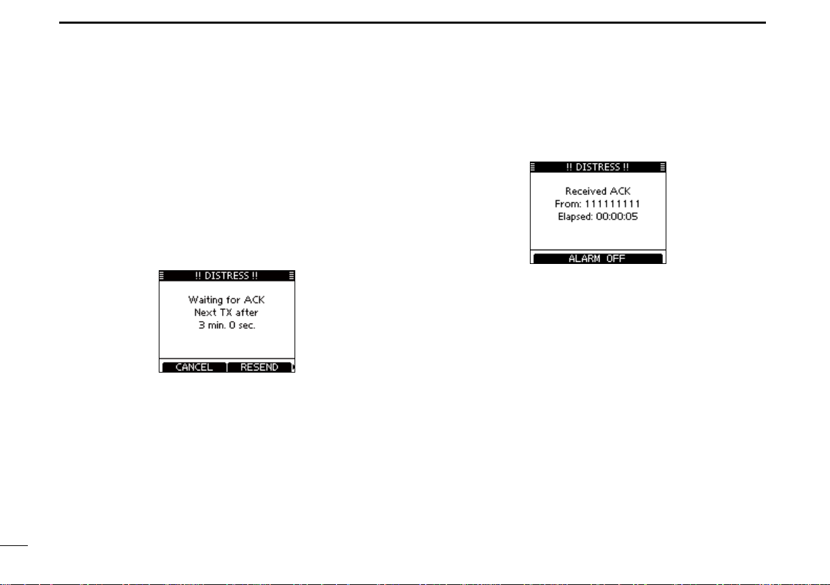
w After transmitting the alert, the transceiver waits for an ac-
knowledgment call.
• The Distress alert is automatically transmitted every 3.5 to 4.5
minutes, until an acknowledgement is received (‘Call repeat’
mode), or a DSC Cancel call is made. (p. 27)
• Push [RESEND] to manually transmit the Distress repeat alert.
• Push [Ω]/[≈] then push [INFO] to display the transmitted Dis-
tress call information.
• Push [Ω]/[≈] then push [P AUSE] to pause the ‘Call repeat’ mode ,
push [RESUME COUNTDOWN] to resume it.
e After receiving the acknowledgment, push [ALARM OFF]
then reply using the microphone.
➥ A distress alert default contains:
• Nature of distress: Undesignated distress
• Position information: The latest GPS or manual input position
is held for 23.5 hours, or until the power is
turned OFF.
22
Page 29
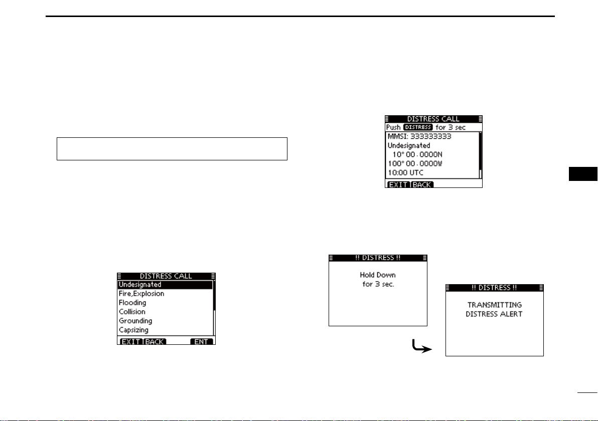
D Regular call
The nature of the Distress call should be included in the Distress call.
DSC OPERATION
e The Distress call confirmation screen is displayed.
• Rotate dial or push [Y]/[Z] to see the hidden lines.
7
1
2
3
q Select “DISTRESS CALL” in the DSC menu.
MENU
(Push [MENU]) (Select icon)
w Select the nature of the distress using dial or [Y]/[Z], then
push dial or [ENT].
• ‘Undesignated, ’ ‘Fire,Explosion, ’ ‘Flooding, ’ ‘Collision, ’ ‘Grounding, ’
‘Capsizing,’ ‘Sinking,’ ‘Adrift,’ ‘Abandoning ship,’ ‘Piracy’ or ‘Man
Overboard’ is selectable.
• The nature of the distress is stored for 30 seconds after a selection is made.
• Push [EXIT] to return to the normal operating mode.
• Push [BACK] to return to the previous screen.
➪ DSC ➪ Distress Call
(Rotate dial, then push [ENT].)
r Hold down [DISTRESS] for 3 seconds to transmit the Dis-
tress alert.
• While holding down [DISTRESS], count down beeps sound and
both the key and display backlighting blink.
• The selected nature of the distress is stored for 30 seconds.
+ Continued on the next page.
4
5
6
7
8
9
10
11
12
13
14
15
16
23
Page 30
DSC OPERATION
7
D Regular call (continued)
t After transmitting the alert, the transceiver waits for an ac-
knowledgment call.
• The Distress alert is automatically transmitted every 3.5 to 4.5
minutes, until an acknowledgement is received (‘Call repeat’
mode), or DSC cancel call is made. (p. 26)
• Push [RESEND] to manually transmit the Distress repeat alert.
• Push [Ω]/[≈] then push [INFO] to display the transmitted Distress call information.
• Push [Ω]/[≈] then push [P AUSE] to pause the ‘Call repeat’ mode ,
push [RESUME COUNTDOWN] to resume it.
y After receiving an acknowledgment call, push [ALARM
OFF] then reply using the microphone.
➥ A distress alert contains:
• Nature of distress: Selected in step w.
• Position information: The latest GPS or manual input position
is held for 23.5 hours, or until the power is
turned OFF.
24
Page 31

When no GPS receiver is connected, and both position
and time have been manually entered, the screen as
shown below appears. Edit y our latitude and longitude position and UTC time as follows:
➥ Push [CHG], then edit your latitude and longitude posi-
tion and UTC time.
• Select a desired number using [Y]/[Z]/[Ω]/[≈].
• Push [ENT] or dial to set it.
• To move the cursor, rotate dial or select either arrow, “←” or
“→,” then push [ENT] or Dial.
• Select N (North latitude) or S (South latitude) when the cursor is on the ‘N’ or ‘S’ position.
• Select W (West longitude) or E (East longitude) when the
cursor is on the ‘W’ or ‘E’ position.
DSC OPERATION
7
1
2
3
4
5
6
7
8
9
10
11
12
13
14
15
16
25
Page 32

DSC OPERATION
7
D Distress cancel call
q While waiting for an acknowledgment call, push [CAN-
CEL].
r The Distress cancel call is transmitted.
26
w Push [CONTINUE].
• Push [BACK] to return to waiting for an acknowledgement call.
e Push [FINISH].
• Push [EXIT] to return to waiting for an acknowledgement call.
t Channel 16 is automatically selected.
• Report your situation using the microphone.
• After the report, push [EXIT] to retur n to the normal operating
mode.
Page 33

DSC OPERATION
7
■ Transmitting DSC calls
To ensure correct operation of the DSC function, make
sure you correctly set the CH70 SQL Level. (p. 64)
D Transmitting an individual call
The Individual call function enables you to transmit a DSC
signal to only a specific station.
q Select “INDIVIDUAL CALL” in the DSC CALLS menu.
MENU ➪ DSC ➪ Individual Call
(Push [MENU]) (Select icon)
w Select the desired preset individual address, or “Manual
Input,” using dial or [Y]/[Z], then push [ENT].
• The ID code for the Individual call can be set first. (p. 18)
• When “Manual Input” is selected, enter the 9 digit MMSI ID code
for the individual you wish to call.
• Push [EXIT] to return to the normal operating mode.
• Push [BACK] to return to the previous screen.
(Rotate dial, then push [ENT].)
About Manual Inputting:
Enter a individual ID in the following way:
• Select a number using [Y]/[Z]/[Ω]/[≈].
• Push [ENT] or dial to set it.
• To move the cursor, rotate dial or select either arro w, “←” or “→,”
then push [ENT] or dial.
• The first digit is specified as ‘0’ for a Group ID. If a 9 digit Group
ID is entered, an error beep sounds when pushing [ENT] or dial.
• The first two digits are ‘0’ for any coast station ID.
NOTE: When a coast station is selected in step w, the
voice channel is automatically specified by the coast station. Therefore, skip step e and go directly to step r.
1
2
3
4
5
6
7
8
9
10
11
12
13
14
15
16
+ Continued on the next page.
27
Page 34

DSC OPERATION
7
D Transmitting DSC calls (continued)
e Select a desired intership channel using dial or [Y](CH)/
[Z](CH), then push [ENT].
• Intership channels are already preset into the transceiver in the
recommended order.
r A confirmation screen is displayed.
• Confirm the call contents.
t Push [CALL] to transmit the Individual call.
• If Channel 70 is busy, the tr ansceiver stands b y until the channel
becomes clear.
y Standby on Channel 70 until an acknowledgement is re-
ceived.
u When the acknowledgement ‘Able to comply’ is received,
alarm sounds and the screen below is displayed.
28
Page 35

DSC OPERATION
7
Push [ALARM OFF] to stop the alarm and then select the
intership channel specified in step e.
• A different intership channel will be selected if the station you
called cannot use the channel.
• Reply using the microphone. And go to step i.
Or, when the acknowledgement ‘Unable to comply’ is re-
ceived, alarm sounds and the screen below is displayed.
Push [ALARM OFF] to stop the alarm. Then push [EXIT]
to return to the operating channel (before you entered the
MENU screen).
i After communicating, push [EXIT] to return to the normal
operating mode.
✓ Convenient!
When the optional MA-500TR
connected to your transceiver, you can transmit individual
DSC calls to selected AIS targets on the transponder without
needing to enter the target’s MMSI code.
See pages 65 and 95 for more details.
class b ais transponder
is
1
2
3
4
5
6
7
8
9
10
11
12
13
14
15
16
29
Page 36

DSC OPERATION
7
D Transmitting an Individual Acknowledgement
When receiving an Individual call, you can transmit an acknowledgement (‘Able to Comply,’ ‘Propose New Channel’ or
‘Unable to Comply’) by using the on-screen prompts (Quick
ACK.) Also, you can send an acknowledgement through the
MENU system (Man ual ACK.)
Quick ACK:
q When an Individual call is received, alarm sounds and the
screen below is displayed.
Push [ALARM OFF] to stop the alarm.
• Even if you do not push [ALARM OFF], the alarm stops after 2
minutes, and then the screen in step w is displayed.
w Push [ACK].
e Select one of three options, then push [ENT].
• Push [EXIT] to return to the normal operating mode.
• Push [BACK] to return to the previous screen.
• Able to Comply: Make an acknowledgment call without
any changes.
• Unable to Comply: You cannot make a communication.
The Acknowledgement call (‘Unable to
Comply’) can be automatically transmitted, if set. See page 68 for details.
• Propose New Channel: You can make an acknowledgement
call, but you specify the intership channel. Select a desired intership channel,
using dial, or [Y](CH)/[Z](CH), then
push [ENT].
30
Page 37

DSC OPERATION
7
r The Individual ACK confirmation screen is displayed.
Push [CALL] to transmit an acknowledgement call.
t The screens shown below are displayed.
Manual ACK:
q Select “INDIVIDUAL ACK” in the DSC CALLS menu.
MENU ➪ DSC ➪ Individual ACK
(Push [MENU]) (Select icon)
• When no Individual call has been received, “Individual ACK” item
will not be displayed.
w Select a desired individual address or ID name to reply to,
using dial or [Y]/[Z], then push [ENT].
• Push [EXIT] to return to the normal operating mode.
• Push [BACK] to return to the previous screen.
e Perform steps e to u, as described in “Quick ACK:,” be-
ginning on the previous page.
(Rotate dial, then push [ENT].)
1
2
3
4
5
6
7
8
9
10
11
12
13
14
15
16
y Reply to the call using the microphone.
u Push [EXIT] to return to the normal operating mode.
31
Page 38

DSC OPERATION
7
D Transmitting a Group call
The Group call function allows you to transmit a DSC signal
to only a specific group.
q Select “GROUP CALL” in the DSC CALLS menu.
MENU ➪ DSC ➪ Group Call
(Push [MENU]) (Select icon)
w Select the desired preset group address or “Manual Input,”
using dial or [Y]/[Z], then push [ENT].
• The ID code for the Group call can be set first. (p. 19)
• When “Manual Input” is selected, set the 8 digit ID code for the
group you wish to call.
• Push [EXIT] to return to the normal operating mode.
• Push [BACK] to return to the previous screen.
(Rotate dial, then push [ENT].)
e Select a desired intership channel using dial or [Y](CH)/
[Z](CH), then push [ENT].
• Intership channels are already preset into the transceiver in the
recommended order.
About Manual Inputting:
Enter a desired group ID in the following way:
• Select a desired number using [Y]/[Z]/[Ω]/[≈].
• Push [ENT] or dial to set it.
• To move the cursor, rotate dial or select either arro w, “←” or “→,”
then push [ENT] or dial.
• The first digit is specified as ‘0’ for a Group ID.
• The first two digits are ‘0’ for any Coast station ID.
32
Page 39

DSC OPERATION
7
r A confirmation screen is displayed.
• Confirm the call contents.
t Push [CALL] to transmit the Group call.
• If Channel 70 is busy, the tr ansceiver stands b y until the channel
becomes clear.
y After the Group call has been transmitted, the following
screen is displayed.
u Announce the information using the microphone.
i After the announcement, push [EXIT] to return to the nor-
mal operating mode.
1
2
3
4
5
6
7
8
9
10
11
12
13
14
15
16
33
Page 40

DSC OPERATION
7
D Transmitting an All Ships call
All ships, that have DSC transceiver, use Channel 70 as their
‘listening channel. ’ When you w ant to announce a message to
these ships within range, use the ‘All Ships Call’ function.
q Select “ALL SHIPS CALL” in the DSC CALLS menu.
MENU ➪ DSC ➪ All Ships Call
(Push [MENU]) (Select icon)
w Select a desired category, using dial or [Y]/[Z], then push
[ENT].
• The selectable category may differ, depending on the programmed setting. Ask your dealer for the selectable categories.
• Push [EXIT] to return to the normal operating mode.
• Push [BACK] to return to the previous screen.
(Rotate dial, then push [ENT].)
e Select a desired traffic channel, using dial or [Y]/[Z], then
push [ENT].
• The selected channel is displayed.
r A confirmation screen is displayed.
• Confirm the call contents.
34
Page 41

DSC OPERATION
7
t Push [CALL] to transmit an All Ships call.
• If Channel 70 is busy, the tr ansceiver stands b y until the channel
becomes clear.
y After the All Ships call has been transmitted, the following
screen is displayed.
u Announce the message using the microphone.
i After the announcement, push [EXIT] to return to the nor-
mal operating mode.
1
2
3
4
5
6
7
8
9
10
11
12
13
14
15
16
35
Page 42

DSC OPERATION
7
D Transmitting a Test call
T esting on the e xclusive DSC distress and safety calling channels should be avoided as much as possib le. When testing on
a distress/safety channel is unavoidable, you should indicate
that these are test transmissions.
Normally the test call would require no further communications between the two stations involved.
q Select “TEST CALL” in the DSC CALLS menu.
MENU ➪ DSC ➪ Test Call
(Push [MENU]) (Select icon)
w Select a desired pre-programmed individual address, or
“Manual Input,” then push dial or [ENT].
• The ID code for the Individual call can be set first. (p. 18)
• When “Manual Input” is selected, set the 9 digit MMSI ID code for
the individual you wish to call.
• Push [EXIT] to return to the normal operating mode.
• Push [BACK] to return to the previous screen.
(Rotate dial, then push [ENT].)
About Manual Inputting:
Enter a desired address ID in the following way:
• Select a desired number using [Y]/[Z]/[Ω]/[≈].
• Push [ENT] or dial to set it.
• To move the cursor, rotate dial or select either arrow, “←” or “→,”
then push [ENT] or dial.
• The first digit is specified as ‘0’ for a Group ID . If a 9 digit Group ID
is entered, an error beep sounds when pushing [ENT] or dial.
• The first two digits are ‘0’ for any Coast station ID.
e A confirmation screen is displayed.
• Confirm the call contents.
36
Page 43

DSC OPERATION
7
r Push [CALL] to transmit the Test call.
• If Channel 70 is busy, the tr ansceiver stands b y until the channel
becomes clear.
t After the Test call has been transmitted, the following
screen is displayed.
y When the acknowledgement call is received, alarm sounds
and the following screen is displayed.
u Push [ALARM OFF] to stop the alarm, and then the screen
as shown below is displayed.
i Push [EXIT] to return to the normal operating mode.
1
2
3
4
5
6
7
8
9
10
11
12
13
14
15
16
37
Page 44

DSC OPERATION
7
D Transmitting a Test Acknowledgement call
When the “TEST ACK” in DSC settings is set to ‘Auto’ (p. 61),
the transceiver automatically transmits a reply call when receiving a Test call.
Quick ACK:
q When a Test call is received, alarm sounds and the screen
shown below is displayed.
Push [ALARM OFF] to stop the alarm.
• Even if you do not push [ALARM OFF], the alarm stops after 2
minutes, and then the screen in step w is displayed.
w Push [ACK].
• Push [IGN] to ignore the call and return to the nor mal operating
mode.
• Push [INFO] to display the Test call information.
About Received call information:
• Push [IGN] to ignore the call and return to the normal operating
mode.
• Push [BACK] to return to the previous screen.
• Push [ACK] to go to the next step.
e The Test ACK confirmation
screen is displayed.
Push [CALL] to transmit the
acknowledgement call.
• Push [EXIT] to return to the
normal operating mode.
r While transmitting the ac-
knowledgement call, the
screen shown to the right is
displayed, and then returns
to the normal operating
mode.
38
Page 45

DSC OPERATION
7
Manual ACK:
q Select “TEST ACK” in the DSC CALLS menu.
MENU ➪ DSC ➪ Test ACK
(Push [MENU]) (Select icon)
• If no Test call has been received, the “Test ACK” item will not be
displayed.
• Push [EXIT] to return to the normal operating mode.
• Push [BACK] to return to the previous screen.
w Select a desired Test call to reply to, using dial or [Y]/[Z],
then push [ENT].
(Rotate dial, then push [ENT].)
e The Test ACK confirmation screen is displayed.
Push [CALL] to transmit the acknowledgement call.
r While transmitting the acknowledgement call, the screen
shown below is displayed, and then returns to the nor mal
operating mode.
1
2
3
4
5
6
7
8
9
10
11
12
13
14
15
16
39
Page 46

DSC OPERATION
7
D Transmitting a Position Reply call
Transmit a Position Reply call when a Position Request call
is received.
When the “POSITION ACK” in DSC Settings is set to ‘Auto’
(p. 61), the transceiver automatically transmits a reply call
when receiving a Position Request call.
Quick Reply:
q When a P osition Request call
is received, alarm sounds
and the screen shown to the
right is displayed.
Push [ALARM OFF] to stop
the alarm.
• Even if you do not push
[ALARM OFF], the alarm stops
after 2 minutes, and then the
screen in step w is displayed.
w Push [ACK].
• Push [IGN] to ignore the call
and return to the normal operating mode.
• Push [INFO] to display the Position Request call information.
About Received call information:
• Push [IGN] to ignore the call and return to the normal operating
mode.
• Push [BACK] to return to the previous screen.
• Push [ACK] to go to the next step.
e The Position Reply confirma-
tion screen is displayed.
Push [CALL] to transmit the
reply call.
• Push [EXIT] to return to the
normal operating mode.
r While transmitting the reply
call, the screen shown to the
right is displayed, and then
returns to the normal operating mode.
40
Page 47

DSC OPERATION
7
Manual Reply:
q Select “POSITION REPLY” in the DSC CALLS menu.
MENU ➪ DSC ➪ Position Reply
(Push [MENU]) (Select icon)
• If no Position Request call has
been received, the “Position
Reply” item will not be displayed.
• Push [BACK] to return to the
previous screen.
• Push [EXIT] to return to the
normal operating mode.
w Select a desired Position
Request call to reply to, using dial or [Y]/[Z], then push
[ENT].
e The Position Reply call
confirmation screen is displayed.
Push [CALL] to transmit the
acknowledgement call.
(Rotate dial, then push [ENT].)
r While transmitting the reply call, the screen shown below
is displayed, and then the transceiv er returns to the normal
operating mode.
When no GPS receiver is connected, and both position and
time have been manually programmed, the screen shown
below is displayed. Edit your latitude and longitude position
and UTC time as follows:
➥ Push [CHG], then edit your latitude and longitude position
and UTC time.
• Select a desired number using [Y]/[Z]/[Ω]/[≈].
• Push [ENT] or dial to set it.
• To move the cursor, rotate dial or select either arrow, “←” or
“→,” then push [ENT] or dial.
• Select N (North latitude) or S (South latitude) when the cursor
is on the ‘N’ or ‘S’ position.
• Select W (West longitude) or E (East longitude) when the cursor is on the ‘W’ or ‘E’ position.
1
2
3
4
5
6
7
8
9
10
11
12
13
14
15
16
41
Page 48

DSC OPERATION
7
D Transmitting a Position Report Reply call
Transmit a Position Report Reply call when a Position Report
call is received.
Quick Reply:
q When a Position Report is received, alarm sounds and the
screen shown below is displayed.
Push [ALARM OFF] to stop the alarm.
• Even if you do not push [ALARM OFF], the alarm stops after 2
minutes, and then the screen in step w is displayed.
w Push [ACK].
• Push [EXIT] to return to the normal operating mode.
• Push [INFO] to display the Position Report Request call informa-
tion.
About Received call information:
• Push [EXIT] to return to the normal operating mode.
• Push [BACK] to return to the previous screen.
• Push [ACK] to go to the next step.
e The Position Report Reply confirmation screen is dis-
played.
Push [CALL] to transmit the reply call.
r While transmitting the reply call, the screen shown below
is displayed, and then returns to the normal operating
mode.
42
Page 49

DSC OPERATION
7
Manual Reply:
q Select “REPORT REPLY” in the DSC CALLS menu.
MENU ➪ DSC ➪ Position Report Reply
(Push [MENU]) (Select icon)
• If no Position Report Request call has been received, the “Position Report Reply” item will not be displayed.
• Push [BACK] to return to the previous screen.
• Push [EXIT] to return to the normal operating mode.
w Select a desired Position Report Request call to reply to,
using dial or [Y]/[Z], then push [ENT].
(Rotate dial, then push [ENT].)
e The Position Report Reply call confir mation screen is dis-
played.
Push [CALL] to transmit the acknowledgement call.
r While transmitting the reply call, the screen shown below
is displayed, and then the transceiv er returns to the normal
operating mode.
1
2
3
4
5
6
7
8
9
10
11
12
13
14
15
16
43
Page 50

DSC OPERATION
7
D Transmitting a Polling Request Reply call
Transmit a Polling Request Reply call when a P olling Request
call is received.
When the “POSITION ACK” in DSC Settings is set to ‘Auto’
(p. 61), the transceiver automatically transmits a reply call
when receiving a Polling Request call.
Quick Reply:
q When a Polling Request call
is received, alarm sounds
and the screen shown to the
right is displayed.
Push [ALARM OFF] to stop
the alarm.
• Even if you do not push
[ALARM OFF], the alarm stops
after 2 minutes, and then the
screen in step w is displayed.
w Push [ACK].
• Push [IGN] to ignore the call
and return to the normal operating mode.
• Push [INFO] to display the Poll-
ing Request call information.
About Received call information:
• Push [IGN] to ignore the call and return to the normal operating
mode.
• Push [BACK] to return to the previous screen.
• Push [ACK] to go to the next step.
e The Polling Request Reply
confirmation screen is displayed.
Push [CALL] to transmit the
reply call.
• Push [EXIT] to return to the
normal operating mode.
r While transmitting the reply
call, the screen shown to the
right is displayed, and then
returns to the normal operating mode.
44
Page 51

DSC OPERATION
7
Manual Reply:
q Enter “POLLING REPLY” in the DSC CALLS menu.
MENU ➪ DSC ➪ Polling Reply
(Push [MENU]) (Select icon)
• If no Polling Request call has been received, the “Polling Reply”
item will not be displayed.
• Push [BACK] to return to the previous screen.
• Push [EXIT] to return to the normal operating mode.
w Select a desired Polling Request call to be replied, using
dial or [Y]/[Z], then push [ENT].
(Rotate dial, then push [ENT].)
e
The Polling Request Reply call confirmation screen is displayed.
Push [CALL] to transmit the acknowledgement call.
r While transmitting the reply call, the screen shown below
is displayed, and then the returns to the normal operating
mode.
1
2
3
4
5
6
7
8
9
10
11
12
13
14
15
16
45
Page 52

DSC OPERATION
7
■ Receiving DSC calls
D Receiving a Distress Call
When a Distress Call is received:
➥ The emergency alarm sounds for 2 minutes.
➥ “ RCVD DISTRESS” appears and the backlight blinks.
q Push [ALARM OFF] to stop the alarm and the blinking
backlight.
• Even if you do not push [ALARM OFF], the alarm stops after 2
minutes, and then the screen in step w is displayed.
w Push a softkey to select your desired action.
[IGN]
➥ Push to return to the normal operating mode.
• The transceiver exits the DSC mode.
• By pushing [PTT], the transceiver also exits the DSC mode.
• The “ ” icon continues to blink and the Call is stored in the
Received Call Log.
[INFO]
➥ Push to display the Received call information. (p. 58)
[ACPT]
➥ Push to accept the call.
And then, push [CH 16] to switch the operating channel
to Channel 16, and then monitor it, as a coast station
may require assistance.
• Even if you haven’t pushed [CH 16] within 10 seconds, the
operating channel automatically switches to Channel 16. (p.
69)
Push
46
Page 53

DSC OPERATION
7
D Receiving a Distress Acknowledgement
When a Distress Acknowledgement sent to another ship is
received:
➥ The emergency alarm sounds for 2 minutes.
➥ “ RCVD DISTRESS ACK” appears and the backlight
blinks.
q Push [ALARM OFF] to stop the alarm and the blinking
backlight.
• Even if you do not push [ALARM OFF], the alarm stops after 2
minutes, and then the screen in step w is displayed.
w Push a softkey to select your desired action.
[IGN]
➥ Push to return to the nor-
mal operating mode.
• The transceiver exits the
DSC mode.
• By pushing [PTT], the transceiver also exits the DSC
mode.
• The “ ” icon continues to
blink and the Call is stored
in the Received Call Log.
[INFO]
➥ Push to display the Received call information. (p. 58)
[ACPT]
➥ Push to accept the call.
And then, push [CH 16] to switch the operating channel
to Channel 16, and then monitor it, as a coast station
may require assistance.
• Even if you haven’t pushed [CH 16] within 10 seconds, the
operating channel automatically switches to Channel 16. (p.
69)
Push
1
2
3
4
5
6
7
8
9
10
11
12
13
14
15
16
47
Page 54

DSC OPERATION
7
D Receiving a Distress Relay Call
When a Distress Relay call is received:
➥ The emergency alarm sounds for 2 minutes.
➥ “ RCVD DISTRESS RELAY” appears and the backlight
blinks.
q Push [ALARM OFF] to stop the alarm and the blinking
backlight.
• Even if you do not push [ALARM OFF], the alarm stops after 2
minutes, and then the screen in step w is displayed.
w Push a softkey to select your desired action.
[IGN]
➥ Push to return to the normal operating mode.
• The transceiver exits the DSC mode.
• By pushing [PTT], the transceiver also exits the DSC mode.
• The “ ” icon continues to blink and the Call is stored in the
Received Call Log.
[INFO]
➥ Push to display the Received call information. (p. 58)
[ACPT]
➥ Push to accept the call.
And then, push [CH 16] to switch the operating channel
to Channel 16, and then monitor it, as a coast station
may require assistance.
• Even if you haven’t pushed [CH 16] within 10 seconds, the
operating channel automatically switches to Channel 16. (p.
69)
Push
4848
Page 55

D Receiving a Distress Relay Acknowledgement
When a Distress Relay Acknowledgement is received:
➥ The emergency alarm sounds for 2 minutes.
➥ “ RCVD DTRS RELAY ACK” appears and the backlight
blinks.
q Push [ALARM OFF] to stop the alarm and the blinking
backlight.
• Even if you do not push [ALARM OFF], the alarm stops after 2
minutes, and then the screen in step w is displayed.
w Push a softkey to select your desired action.
DSC OPERATION
[IGN]
➥ Push to return to the normal operating mode.
• The transceiver exits the DSC mode.
• By pushing [PTT], the transceiver also exits the DSC mode.
• The “ ” icon continues to blink and the Call is stored in the
Received Call Log.
[INFO]
➥ Push to display the Received call information. (p. 58)
[ACPT]
➥ Push to accept the call.
And then, push [CH 16] to switch the operating channel
to Channel 16, and then monitor it, as a coast station
may require assistance.
• Even if you haven’t pushed [CH 16] within 10 seconds, the
operating channel automatically switches to Channel 16. (p.
62)
Push
7
1
2
3
4
5
6
7
8
9
10
11
12
13
14
15
16
4949
Page 56

DSC OPERATION
7
D Receiving an Individual Call
When an Individual Call is received:
➥ The alarm sounds for 2 minutes.
➥ “RCVD INDIVIDUAL CALL” appears. The backlight may
blink for 2 minutes, depending on the received Category.
q Push [ALARM OFF] to stop the alarm and the blinking
backlight.
• Even if you do not push [ALARM OFF], the alarm stops after 2
minutes, and then the screen in step w is displayed.
w Push a softkey to select your desired action.
[IGN]
Push to ignore the Call and return to the normal operating
➥
mode.
• The transceiver exits the DSC mode.
• The “ ” icon continues to blink and the Call is stored in the
Received Call Log.
[INFO]
➥ Push to display the Received call information. (p. 58)
[ACK]
➥ Push to display the “INDIVIDUAL ACK” screen to reply
to the Call. Select one of three options, depending on
your situation. See page 31 for details of the Individual
Acknowledgement procedure.
5050
When “INDIVIDUAL ACK” is set to “Auto (Unable),” the
transceiver automatically replies to the Call. In that case,
both the TX and RX calls are stored in the Transmitted and
Received Call Logs.
Page 57

DSC OPERATION
7
D Receiving a Group Call
When a Group Call is received:
➥ The alarm sounds for 2 minutes.
➥ “RCVD GROUP CALL” appears. The backlight may blink
for 2 minutes, depending on the received Category.
q Push [ALARM OFF] to stop the alarm and the blinking
backlight.
• Even if you do not push [ALARM OFF], the alarm stops after 2
minutes, and then the screen in step w is displayed.
w Push a softkey to select your desired action.
[IGN]
➥ Push to ignore the Call and return to the normal operat-
ing mode.
• The transceiver exits the DSC mode.
• The “ ” icon continues to blink and the Call is stored in the
Received Call Log.
[INFO]
➥ Push to display the Received call information. (p. 58)
[ACPT]
➥ Push to monitor the channel specified by the calling sta-
tion (Example: 08) for an announcement from the calling station.
1
2
3
4
5
6
7
8
9
10
11
12
13
14
15
16
5151
Page 58

DSC OPERATION
7
D Receiving an All Ships Call
When an All Ships Call is received:
➥ The alarm sounds for 2 minutes.
➥ “RCVD ALL SHIPS CALL” appears. The backlight may
blink for 2 minutes, depending on the received Category.
q Push [ALARM OFF] to stop the alarm and the blinking
backlight.
• Even if you do not push [ALARM OFF], the alarm stops after 2
minutes, and then the screen in step w is displayed.
w Push a softkey to select your desired action.
[IGN]
➥ Push to ignore the Call and return to the normal operat-
ing mode.
• The transceiver exits the DSC mode.
• The “ ” icon continues to blink and the Call is stored in the
Received Call Log.
[INFO]
➥ Push to display the Received call information. (p. 58)
[ACPT]
➥ Push to monitor the channel specified by the calling sta-
tion (Example: 16) for an announcement from the calling station.
5252
Page 59

DSC OPERATION
7
D Receiving a Geographical Area Call
When a Geographical Area Call (for the area you are in) is
received:
➥ The alarm sounds for 2 minutes.
➥ “RCVD GEOGRAPHICAL” appears. The backlight may
blink for 2 minutes, depending on the received Category.
q Push [ALARM OFF] to stop the alarm and the blinking
backlight.
• Even if you do not push [ALARM OFF], the alarm stops after 2
minutes, and then the screen in step w is displayed.
w Push a softkey to select your desired action.
[IGN]
➥ Push to ignore the Call and return to the normal operat-
ing mode.
• The transceiver exits the DSC mode.
• The “ ” icon continues to blink and the Call is stored in the
Received Call Log.
[INFO]
➥ Push to display the Received call information. (p. 58)
[ACPT]
➥ Push to monitor the channel specified by the calling sta-
tion (Example: 08) for an announcement from the calling station.
When no GPS receiver is connected or if there is a problem with the connected receiver, all Geographical Area
Calls are received, regardless of your position.
1
2
3
4
5
6
7
8
9
10
11
12
13
14
15
16
5353
Page 60

DSC OPERATION
7
D Receiving a Position Request Call
When a Position Request Call is received:
➥ The alarm sounds for 2 minutes.
➥ “RCVD POS REQUEST” appears. The backlight blinks for
2 minutes.
q Push [ALARM OFF] to stop the alarm and the blinking
backlight.
• Even if you do not push [ALARM OFF], the alarm stops after 2
minutes, and then the screen in step w is displayed.
w Push a softkey to select your desired action.
[IGN]
➥ Push to ignore the Call and return to the normal operat-
ing mode.
• The transceiver exits the DSC mode.
• The “ ” icon continues to blink and the Call is stored in the
Received Call Log.
[INFO]
➥ Push to display the Received call information. (p. 58)
[ACK]
➥ Push to display the “POSITION REPLY” screen and
send a reply to the Call. (p. 40)
When “POSITION ACK” is set to “A uto ,” the transceiver au-
tomatically replies to the Call. In that case , both the TX and
RX calls are stored in the Transmitted and Received Call
Logs.
5454
Page 61

DSC OPERATION
7
D Receiving a Position Report Call
When a Position Report Call is received:
➥ The alarm sounds for 2 minutes.
➥ “RCVD POSITION REPOR T” appears. The backlight blinks
for 2 minutes.
q Push [ALARM OFF] to stop the alarm and the blinking
backlight.
• Even if you do not push [ALARM OFF], the alarm stops after 2
minutes, and then the screen in step w is displayed.
w Push a softkey to select your desired action.
[EXIT]
➥ Push to ignore the Call and return to the normal operat-
ing mode.
• The transceiver exits the DSC mode.
• The “ ” icon continues to blink and the Call is stored in the
Received Call Log.
[INFO]
➥ Push to display the Received call information. (p. 58)
1
2
3
4
5
6
7
8
9
10
11
12
13
14
15
16
5555
Page 62

DSC OPERATION
7
D Receiving a Polling Request call
When a Polling Request call is received:
➥ The alarm sounds for 2 minutes.
➥ “RCVD POLLING REQUEST” appears. The backlight
blinks for 2 minutes.
q Push [ALARM OFF] to stop the alarm and the blinking
backlight.
• Even if you do not push [ALARM OFF], the alarm stops after 2
minutes, and then the screen in step w is displayed.
w Push a softkey to select your desired action.
[IGN]
➥ Push to ignore the Call and return to the normal operat-
ing mode.
• The transceiver exits the DSC mode.
• The “ ” icon continues to blink and the Call is stored in the
Received Call Log.
[INFO]
➥ Push to display the Received call information. (p. 58)
[ACK]
➥ Push to display the “POLLING REPLY” screen to reply
to the Call. (p. 44)
When “POSITION ACK” is set to “A uto ,” the transceiver au-
tomatically replies to the Call. In that case , both the TX and
RX calls are stored in the Transmitted and Received Call
Logs.
5656
Page 63

DSC OPERATION
7
D Receiving a Test Call
When a Test Call is received:
➥ The alarm sounds for 2 minutes.
➥ “RCVD TEST CALL” appears. The backlight blinks for 2
minutes.
q Push [ALARM OFF] to stop the alarm and the blinking
backlight.
• Even if you do not push [ALARM OFF], the alarm stops after 2
minutes, and then the screen in step w is displayed.
w Push a softkey to select your desired action.
[IGN]
➥ Push to ignore the Call and return to the normal operat-
ing mode.
• The transceiver exits the DSC mode.
• The “ ” icon continues to blink and the Call is stored in the
Received Call Log.
[INFO]
➥ Push to display the Received call information. (p. 58)
[ACK]
➥ Push to display the “TEST ACK” screen to reply to the
Call. (p. 38)
When “TEST ACK” is set to “Auto,” the transceiver automatically replies to the Call. In that case, both the TX and
RX calls are stored in the Transmitted and Received Call
Logs.
1
2
3
4
5
6
7
8
9
10
11
12
13
14
15
16
5757
Page 64

DSC OPERATION
7
D Receiving a Test Acknowledgement Call
When a Test Acknowledgement Call is received:
➥ The alarm sounds for 2 minutes.
➥ “Received ACK” is displayed. The backlight blinks for 2
minutes.
q Push [ALARM OFF] to stop
the alarm and the blinking
backlight.
• Even if you do not push [ALARM
OFF], the alarm stops after 2
minutes, and then the screen in
step w is displayed.
w Push a softkey to select your
desired action.
[EXIT]
➥ Push to retur n to the nor-
mal operating mode.
• The transceiver exits the
DSC mode.
• “ ” continues to blink and
the Call is stored in the Received Call Log.
■ Received Call log
The transceiver automatically stores up to 50 distress messages and 50 other messages, and they can be used as a
supplement to your logbook.
• While in the normal operating mode, the “ ” icon blinks in the upper right corner of the LCD when there is an unread DSC message.
D Distress message
q Push the softkey [LOG] to enter “RCVD CALL LOG” in the
DSC CALLS menu, or you can enter it through the Menu
screen.
MENU ➪ DSC ➪
(Push [MENU]) (Select icon)
w Push [Y]/[Z] to select “Distress,” then push [ENT].
• The Distress messages are stored in “Distress.”
• The “ ” icon appears when there are unread DSC messages.
• The “ ” icon appears when there are no unread DSC mes-
sages.
• No icon appears when there are no DSC messages.
• Push [BACK] to return to the previous screen.
• Push [EXIT] to return to the normal operating mode.
Received Call Log
(Rotate dial, then push [ENT].)
5858
Page 65

e Rotate dial or push [Y]/[Z] to select the desired item, then
push [ENT].
r Rotate dial or push [Y]/[Z] to scroll the DSC message
contents.
DSC OPERATION
7
D Other messages
q Push [LOG] to enter “RCVD CALL LOG” in the DSC CALLS
menu, or you can enter it through the Menu screen.
MENU ➪ DSC ➪
(Push [MENU]) (Select icon)
w Push [Y]/[Z] to select “Others,” then push [ENT].
• The messages other than the Distress are stored in “Others.”
• The “ ” icon appears when there are unread DSC messages.
• The “ ” icon appears when there are no unread DSC messages.
• No icon appears when there are no DSC messages.
• Push [BACK] to return to the previous screen.
• Push [EXIT] to return to the normal operating mode.
Received Call Log
(Rotate dial, then push [ENT].)
1
2
3
4
5
6
7
8
9
10
11
12
13
t To delete the displayed DSC message, push [DEL].
• The confirmation screen is displayed, then push [OK] to delete.
y Push [EXIT] to return to the normal operating mode.
14
15
16
☞ Continued on the next page
5959
Page 66

DSC OPERATION
7
D Other messages (Continued)
e Rotate dial or push [Y]/[Z] to select the desired item, then
push [ENT].
r Rotate dial or push [Y]/[Z] to scroll the DSC message
contents.
• The stored message has various information, depending on the
DSC call type.
t To delete the displayed DSC message, push [DEL].
• The confirmation screen is displayed, then push [OK] to delete.
y Push [EXIT] to return to the normal operating mode.
■ Transmitted Call log
The transceiver automatically stores up to 50 transmitted
calls, and the log can be used as a supplement to your logbook.
q Select “TX CALL LOG” in the DSC CALLS menu.
MENU ➪ DSC ➪
(Push [MENU]) (Select icon)
• Push [BACK] to return to the previous screen.
• Push [EXIT] to return to the normal operating mode.
w Rotate dial or push [Y]/[Z] to select the desired item, then
push [ENT].
e Rotate dial or push [Y]/[Z] to scroll the DSC message
contents.
r To delete the displayed DSC message, push [DEL].
• The confirmation screen is displayed, then push [OK] to delete.
t Push [EXIT] to return to the normal operating mode.
Transmitted Call Log
(Rotate dial, then push [ENT].)
6060
Page 67

DSC OPERATION
7
■ DSC Settings
D Position Input (See page 21)
D Add Individual ID/Group ID (See pages 18, 19)
D Delete Individual ID/Group ID (See page 20)
D Automatic Acknowledgement
These items set the Automatic Acknowledgement function to
“Auto” or “Manual.”
When an Individual, Position Request, Polling Request or
Test Call is received, the transceiver automatically transmits
an Individual Acknowledgement, Position Reply, Polling Reply or Test Acknowledgement Call, respectively.
When “INDIVIDUAL ACK” is set to “Auto,” the transceiver
automatically transmits the Acknowledgment call including
“Unable to Comply” (No Reason Given) after receiving the
Individual call.
q
Select either “INDIVIDUAL A CK, ” “POSITION ACK” or “TEST
ACK” in the DSC Settings menu.
MENU ➪ DSC SET ➪
(Push [MENU]) (Select icon)
MENU ➪ DSC SET ➪
MENU ➪ DSC SET ➪
Position ACK
Test ACK
Individual ACK
(Rotate dial, then push [ENT].)
w Rotate dial or push [Y]/[Z]
then push [ENT].
• Push [BACK] to cancel and return to the DSC Settings menu.
to select “Auto” or “Manual”
(default)
(default)
(default)
1
2
3
4
5
6
7
8
9
10
11
12
13
14
15
16
e Push [EXIT] to return to the normal operating mode.
6161
Page 68

DSC OPERATION
7
D Channel 16 Switch function
By regulation, after receiving a Distress call, the transceiver switches the operating channel to Channel 16. However,
when this setting is set to “OFF,” the function enables the
transceiver to remain on the operating channel, even after
receiving a Distress call.
q Select “CH 16 SWITCH”
MENU ➪ DSC SET ➪ CH 16 Switch
(Push [MENU]) (Select icon)
w Rotate dial or push [Y]/[Z] to set the Channel 16 Switch
function to “Auto (No Delay),” “10 Second Delay” or “OFF
then push [ENT].
• Push [BACK] to return to the previous screen.
in the DSC Settings menu
(Rotate dial, then push [ENT].)
(default)
.
,”
Auto (No Delay): After receiving a Distress call, and
[ACPT] is pushed on the confirmation
screen, the transceiver immediately
switches to Channel 16.
10 Second Delay: After receiving a Distress call, and
[ACPT] is pushed on the confirmation
screen, the transceiver remains on the
current operating channel for 10 seconds. After that, the transceiver automatically switches to Channel 16.
(default)
OFF : Even after receiving a Distress call, the
transceiver remains on the operating
channel.
e Push [EXIT] to return to the normal operating mode.
• The “ ” icon appears.
62
Page 69

DSC OPERATION
7
D DSC Data Output
Select an option for the DSC Data Output function.
When receiving a DSC call, this function makes the transceiver send the DSC data from its NMEA Output port to a
connected device.
q Select “DSC DATA OUTPUT”
MENU ➪ DSC SET ➪ DSC Data Output
(Push [MENU]) (Select icon)
w Rotate dial or push [Y]/[Z] to set the DSC Data Output
function to “All Stations,” “Station List” or “OFF
push [ENT].
• Push [BACK] to return to the previous screen.
All Stations: Outputs the call from any vessel from the
NMEA Output port.
Station List: Outputs the call from any vessels listed on the
Individual ID screen.
OFF: Does not
ment.
e Push [EXIT] to return to the normal operating mode.
in the DSC Settings menu
(Rotate dial, then push [ENT].)
,” and then
(default)
output any call to external equip-
.
D Alarm Status
Set the Alarm function ON or OFF, depending on the Category or Status.
q Select “ALARM STATUS”
MENU ➪ DSC SET ➪ Alarm Status
(Push [MENU]) (Select icon)
w Rotate dial or push [Y]/[Z] to select
push [ENT].
• Push [BACK] to cancel and return to the DSC Settings menu.
• “ Safety ,” “Routine, ” “W arning, ” “Self-Terminate” and “Discrete” are
selectable. (default: ON)
e Rotate dial or push [Y]/[Z] to set the Alarm setting to “ON”
or “OFF, and then push [ENT].”
r Push [EXIT] to return to the normal operating mode.
in the DSC Settings menu
(Rotate dial, then push [ENT].)
the status, and then
.
1
2
3
4
5
6
7
8
9
10
11
12
13
14
15
16
63
Page 70

DSC OPERATION
7
D Channel 70 Squelch level
Set the squelch level on Channel 70.
The transceiver has 11 squelch levels between 1 (loose
squelch) and 10 (tight squelch) and OPEN.
OPEN is completely open.
q Select “CH 70 SQL LEVEL”
MENU ➪ DSC SET ➪ CH 70 SQL Level
(Push [MENU]) (Select icon)
w Rotate dial or push [Y]/[Z][Ω]/[≈] to adjust the squelch
level until the noise just disappears, then push [ENT].
• Push [BACK] to cancel and return to the previous screen.
e Push [EXIT] to return to the normal operating mode.
in the DSC Settings menu
(Rotate dial, then push [ENT].)
(default)
.
D DSC Loop Test
The DSC loop test function sends transmit DSC signals to
the receive AF circuit to compare and check the TX and RX
signals at the AF level.
q Select “DSC LOOP TEST”
MENU ➪ DSC SET ➪ DSC Loop Test
(Push [MENU]) (Select icon)
w Push [ENT] to start the DSC loop test.
• Push [BACK] to cancel and return to the DSC Settings menu.
• When the transmit DSC and receive DSC signals match, “OK”
appears.
e Push [EXIT] to return to the normal operating mode.
If “NG” appears in step w, either or both TX and RX DSC
circuits have a problem. In that case, you will have to send
the transceiver to your nearest dealer for repair.
in the DSC Settings menu
(Rotate dial, then push [ENT].)
.
64
Page 71

DSC OPERATION
7
■ Making an Individual call using an AIS transponder
When the optional MA-500TR CLASS B AIS TRANSPONDER is
connected to your transceiver, an individual DSC call can be
transmitted to a selected AIS target, without needing to enter
the target’s MMSI code. In this case, the call type is automatically set to Routine.
See page 95 for connecting instructions.
To ensure correct operation of the DSC function, make
sure you correctly set the CH70 SQL Level. (p. 64)
Step 1: Transponder’s operation
q Select a desired AIS target on the plotter, target list or dan-
ger list display.
• You can also go to the next step whenever the detail screen of
the AIS target is displayed.
• Make sure the transceiver is in the normal operating mode. Oth-
erwise, you cannot make an individual DSC call using the transponder.
w Push [DSC] to display the voice channel selection screen,
and then push [Y]/[Z] to select a desired voice channel*.
• Voice channels are already preset into the transponder in recommended order.
* When a coast station is selected in step q, a voice channel will
be specified by the coast station, therefore you cannot change
the channel. The transponder will display “Voice Channel is
specified by the Base station,” in this case.
Transponder’s display
e Push [DSC] to transmit an individual DSC call to the AIS
target.
• If Channel 70 is busy, the tr ansceiver stands b y until the channel
becomes clear.
• If the transceiver cannot make the call, the transponder will display “DSC T r ansmission FAILED. ”
Transponder’s display
1
2
3
4
5
6
7
Transceiver’s display
8
9
10
11
12
13
14
15
16
Transceiver’s display
65
Page 72

DSC OPERATION
[CLEAR]
7
66
r After making the individual DSC call, the transponder will
display “DSC Transmission COMPLETED.”
• Push [CLEAR] to return to the screen displayed before you entered the voice channel selection screen in step w.
• The transceiver stands by on Channel 70 until an acknowledge-
ment is received.
Transponder’s display Transceiver’s display
Step 2: Transceiver’s operation
t When the acknowledgement is received, alarm sounds.
➥ If the acknowledgement ‘Able to comply
’ is received,
push [ALARM OFF] to stop the alarm, and then select
the intership channel specified in step w.
• A different intership channel will be selected if the station you
called cannot use the channel.
• To reply, push [PTT] and speak at your normal voice level.
• You can check the MMSI code or the name, if programmed,
of the AIS target on the display.
➥ If the acknowledgement ‘Unable to comply’ is received,
push [ALARM OFF] to stop the alarm, and then “INDIVIDUAL CALL FAILED” is displayed.
‘Able to comply’ is received
‘Unable to comply’ is received
y
After the communication is finished, push [EXIT] to return
to the normal operating mode.
[Y]
[Z]
[DSC]
TRANSPONDER
Page 73

OTHER FUNCTIONS
8
■ Intercom operation
The optional Intercom function allows you to talk between the
deck and the cabin. The optional HM-195
required for Intercom operation.
Connect the HM-195
100.
• Transmitting is disabled while using the intercom.
• The received signal is muted while using the intercom.
q Hold down [PWR](Dial) to turn ON the power.
• The command microphone power is automatically turned ON,
even if the power is OFF.
w Push [MENU].
e Rotate dial or push [Ω]/[≈] to
select the “INCM,” icon and
then push the softkey below
the icon.
• The INTERCOM screen is dis-
played.
• Push [BACK] to return to the pre-
vious screen.
r Hold down [INCM CALL] to
sound the intercom beeps.
• The transceiver and the command
microphone sound beeps while
holding down [INCM CALL].
• “CALL” appears.
commandmicIV™ as described on page
commandmicIV™ is
t After releasing [INCM CALL], hold down [PTT] and speak
into the microphone at a normal voice level.
• “ TALK” appears on the caller’s displa y, or “LSTN” appears on the
listener’s display.
•
To adjust the transceiver’s intercom volume level, rotate volume
dial.
• To adjust the HM-195’s intercom volume level, rotate [VOL/SQL]
(Dial) on the HM-195.
y After releasing [PTT], you can hear the response through
the speaker.
u Push [EXIT] to return to normal operating screen.
While in the Intercom mode, the transmit and receive functions are disabled. When the transceiver is transmitting,
the Intercom function is disabled.
On the caller’s display
On the listener’s display
1
2
3
4
5
6
7
8
9
10
11
12
13
14
15
16
67
Page 74

OTHER FUNCTIONS
8
6868
■ RX Hailer function
The RX Hailer function enables you to hear the received audio on the deck or bridge through a Hailer speaker.
Connect an external hailer speaker as described on page 94.
q Push
[RX ]
to enter the RX Hailer mode.
• The RX Hailer volume level adjustment screen is displayed.
w Rotate dial or push [Y]/[Z]/[Ω]/[≈] to adjust the RX Hailer
volume level, and then push [ENT].
• The “RX ”icon appears.
Appears
e
To return to normal operating mode,
• The “RX ” icon disappears.
To adjust the audio output level in the RX Hailer mode,
hold down
volume level adjustment screen, and then rotate dial or
push [Y]/[Z]/[Ω]/[≈]. After adjusting, push [ENT] to set it.
[RX ] for 1 second to display
push
[RX ].
the RX Hailer
■ Hailer operation
The transceiver has a 2 way hailer function, making it unnecessary to leave the bridge to talk with a another party.
Connect an external hailer speaker as described on page 94.
• Transmitting is not possible while using the hailer.
q Push [MENU].
w Rotate dial or push [Ω]/[≈] to select the “HAILER” icon and
then push the softkey below the icon.
• HAILER screen is displayed.
e Hold down [PTT] and speak at a normal voice level.
• While holding down [PTT], the screen below is displayed.
• To adjust the hailer level, rotate dial.
• Push [BACK] to return to the previous screen.
r Push [EXIT] to return to normal operating screen.
While in the hailer mode, the transmit and receive func-
tions are disabled. When the transceiver is transmitting,
the hailer function is disabled.
Page 75

OTHER FUNCTIONS
8
■ Horn function
D Automatic foghorn function
The automatic foghorn function sounds a horn repeatedly
until the function is turned OFF. Four patterns are available
for varying conditions.
TYPE PATTERN USAGE
UNDERWAY
STOP
SAIL
TOW
One 5-second blasts every 120
seconds.
Two 5-second blasts (separated
by 2 seconds) every 120 seconds.
One 5-second blast followed
by two 1-second blasts (each
separated by 2 seconds) every
120 seconds.
One 5-second blast followed
by three 1-second blasts (each
separated by 2-seconds) every
120 seconds.
5s1
5s1
2s
5s1
1s
2s
5s1
1s
2s
The foghorn outputs from the hailer speaker. To use this
function, the hailer speaker must be connected to the transceiver. See page 94 for connection details.
Motor vessel underway and making way.
120s
Motor vessel underway but stopped (not
making way).
120s
Sailing vessel underway, fishing vessel
(underway or anchored), vessel not under
command, a vessel restricted in her ability
120s
120s
to maneuver (underway or at anchor), or a
vessel towing or pushing another ahead.
Vessel under tow (manned).
1
2
3
4
5
6
7
8
9
10
11
12
13
14
15
16
69
Page 76

OTHER FUNCTIONS
8
q Select “Auto Foghorn” in the HORN menu.
MENU ➪ HORN ➪ Auto Foghorn
(Push [MENU]) (Select icon)
(Rotate dial, then push [ENT].)
w Rotate dial or push [Y]/[Z] to
select the desired foghorn pattern, and then push [ENT].
• Push [BACK] to return to the previous screen.
• Push [EXIT] to return to the nor-
mal operating mode.
e Rotate dial or push [Y]/[Z]/[Ω]/
[≈]
to adjust the foghorn level.
• The foghorn level is adjustable in
20 steps.
r Push [MENU] to exit the MENU
screen.
• The horn icon is displayed.
Appears
t To return to normal operation,
select [OFF] in the Auto Foghorn menu.
D Manual Horn function
q Select “Manual Horn” in the HORN menu.
MENU ➪ HORN ➪ Manual Horn
(Push [MENU]) (Select icon)
w Hold down [HORN] to sound a horn.
• While holding down [HORN], the horn sounds, and the screen
below is displayed.
• To adjust the horn volume level, rotate dial.
• Push [BACK] to return to the previous screen.
e Push [EXIT] to return to the normal operating screen.
While in the Horn mode, the transmit and receive functions
are disabled. When the transceiver is transmitting, the
Horn function is disabled.
(Rotate dial, then push [ENT].)
70
70
Page 77

OTHER FUNCTIONS
8
■ Voice scrambler operation
(Available when the scrambler unit is installed)
The voice scrambler provides private communications. In
order to receive or send scrambled transmissions, you must
activate the scrambler function. You also need to program
the scrambler code in the Menu screen. (p. 91)
The scrambler function automatically turns OFF when
Channel 16 or 70 is selected.
q
Select an operating channel except Channel 16 or 70.
w
Push [SCBL] to turn the Voice Scrambler ON or OFF.
• The “SBL” icon appears when the voice scrambler is ON.
D Programming scrambler codes
There are 32 codes (1 to 32) available for programming. Set
the code in the Menu screen. In order to understand each
other, all transceivers in your group must have the same
scramble code. See page 91 for scrambler code setting details.
Appears
■ Voice recorder function
This transceiver has an automatic recording function that can
record the last 120 seconds of the received audio. You can
playback the audio that you could not hear clearly.
Automatically starts recording
when a signal is received.
(Default)
• The “REC” icon appears while recording.
• Stops recording 3 seconds after
the signal disappears.
• Stops recording when the channel
is changed.
• The recorded voice data is erased
when the transceiver is turned
OFF.
D Playback the recorded voice
q Push [PLAY] to playback the
recorded voice.
• The “ ” icon appears while
playing.
1
2
3
4
5
6
7
8
9
10
11
12
13
14
15
16
w Push [STOP] to return to nor-
mal operating screen.
71
Page 78

9
AIS RECEIVER (Depending on versions)
■ About AIS
AIS (The automatic identification system) is primarily used for
collision-risk management and navigation safety. It automatically transmits and receives vessel information, such as the
vessel name, MMSI code, vessel type, position data, speed,
course, destination and more. Information is exchanged
among the vessels and/or base stations on the VHF maritime
mobile band. The information helps to identify other nearby
vessels or stations by displaying the received data on a plotter or a radar screen.
Other vessel
(Class A AIS)
Other vessel
(Class B AIS)
Vessel information
Base Station
■ AIS Classes
There are seven types of AIS stations; v essels, base stations ,
Search and Rescue (SAR), Aids to Navigation (AtoN), Search
and Rescue Transmitter (AIS-SART), MOB (Man OverBoard)
and EPIRB (Emergency Position Indicating Radio Beacon)AIS.
There are two classes of AIS units, which are installed on
vessels; Class A and Class B.
Under the Safety Of Life At Sea (SOLAS) convention, all
SOLAS vessels, as described below, are required to install a
Class A AIS transponder:
• Upwards of 300 gross tonnage engaged on international
voyages.
• Passenger vessels, irrespective of size, engaged on international voyages.
• Upwards of 500 gross tonnage not engaged on international
voyages.
A Class B AIS transponder is designed to be interoperability
with Class A units, but not to impact the Class A network.
Many commercial vessels, and some leisure craft, not classified as requiring a Class A unit, choose to install a Class B
unit to avoid accidents at sea.
7272
Your vessel
(Class B AIS)
Page 79

AIS RECEIVER (Depending on versions)
r
y
e
w
9
■ Function display
There are three types of function display; plotter, target list
and danger list, and you can select your desired type using
the [DISP] key.
q Push [MENU].
w Rotate dial or push [Ω]/[≈] to select the “AIS” icon and then
push the softkey below the icon.
• AIS plotter is displayed.
e
Push [Y]/[Z] to adjust the plotter range.
D Plotter screen
After select the “AIS” icon in the menu screen, the plotter screen
is displayed. If the GPS is connected and it receives signals from
a satellite. It shows the display range and the icons of the AIS
targets.
q
t
q DISPLA Y TYPE
Shows the selected display type. You can select the dis-
play type from “AIS SET” in the menu screen (p. 80)
• When “N-UP” is displayed, the top of the plotter screen represents North.
• When “AC-UP” is displayed, the top of the plotter screen represents the direction your course is heading.
w RANGE/CPA INFORMATION
➥ Shows the range information from your v essel to the se-
lected AIS target.
➥ Shows the CPA (Closest Point of Approach) information
of the selected AIS target whose CPA is within 6 nm
(nautical miles) and TCPA (Time to CPA) is within 60
minutes of your vessel.
e BEARING/TCPA INFORMATION
➥ Shows the bearing information from your vessel to the
selected AIS target.
➥ Shows TCPA information of the selected AIS target
whose CPA is within 6 nm (nautical miles) and TCPA is
within 60 minutes of your vessel.
r TARGET BOX
Shows the selected AIS target.
• When a target box appears, push [ENT] to display the detail
screen of the selected AIS target.
1
2
3
4
4
6
7
8
9
10
11
12
13
14
15
16
7373
Page 80

AIS RECEIVER (Depending on versions)
r
y
q
e
w
9
t
• Description of the icons
Icon Description
AIS target: V essel
The tip of the target triangle automatically points
in the direction it’s heading.
The icon blinks when the AIS target is closer than
your CPA and TCPA settings. (Dangerous target)
AIS target: Lost target*
The target triangle is marked with a diagonal line.
74
t YOUR VESSEL ICON
Your
vessel icon appears in the center of the screen.
• When “N-UP” is displayed, the vessel icon automatically points
in the direction you are heading, in 45 degrees steps.
• When “AC-UP” is displayed, the vessel icon constantly points to
the top of the plotter screen.
• When your vessel moves less than 2 knots, the “ ” icon appears.
y DISPLAY RANGE
Shows the selected display range.
➥ Push [Y]/[Z] to select display range.
• 0.125, 0.25, 0.5, 0.75, 1.5, 3, 6, 12, 24 nm (nautical miles) are
selectable.
AIS target: Base Station
AIS target: Search and Rescue (SAR)
AIS target: Aids to Navigation (AtoN)
AIS target: AIS-SART, MOB and EPIRB-AIS
* A vessel is regarded as a “Lost target” after a specified period of
time has passed since the vessel last transmitted data.
The “Lost target” icon disappears from the plotter screen 6 minutes
and 40 seconds after the vessel was regarded as a “Lost target.”
Ask your dealer for details.
Page 81

AIS RECEIVER (Depending on versions)
9
D Target list screen
In the plotter screen, push [DISP] to switch to the target list
screen, which shows all AIS targets being detected by the
transponder.
The AIS target data is sorted by the distance from your vessel, and the closest target is located on the top of the list.
• Rotate dial or push [∫]/[√] to select an AIS target.
• Push [INFO] or [ENT] to display the detail screen of the selected
AIS target. (p. 76)
• Push [DSC] to transmit DSC call to selected AIS target.
q
w
q THE NUMBER OF TARGETS
Shows the number of AIS targets which are being detected
by the transceiver.
w TARGET INFORMATION
Shows the following AIS target information:
• MMSI code or name, if the name is programmed.
• Range (RNG) from your vessel to the target (unit: nautical mile)
• Bearing (BRG) from your vessel to the target (unit: degree)
D Danger list screen
In the target list display, push [DISP] to switch to the danger list screen, which helps you to find any dangerous target
whose CPA is within 6 nm (nautical miles) and TCPA is within
60 minutes of your vessel.
• Rotate dial or push [∫]/[√] to select an AIS target.
• Push [Ω]/[≈] to change the sort of AIS target data, sort by CPA
or TCP A.
• Push [INFO] or [ENT] to display the detail screen of the selected
AIS target. (p. 76)
• Push [DSC] to transmit DSC call to selected AIS target.
q
w
q THE NUMBER OF DANGEROUS TARGETS
Shows the number of AIS targets which are being detected
by the transceiver.
w DANGER TARGET INFORMATION
Shows the following dangerous target information:
• MMSI code or name, if the name is programmed.
• CPA: Closest Point of Approach (unit: nautical mile)
• TCPA: Time to CPA (unit: minute)
1
2
3
4
5
6
7
8
9
10
11
12
13
14
15
16
75
Page 82

AIS RECEIVER (Depending on versions)
9
■ About the detail screen
The detail screen displays the information about the selected
AIS target. The contents differ, depending on the AIS class.
➥ Push [∫]/[√] to select an AIS target in the target list screen,
danger list screen, or plotter screen and then push [INFO]
or [ENT].
• The detail screen is displayed.
➥ Rotate dial or push [∫]/[√]/[Ω]/[≈] to scroll the page.
➥ Push [EXIT] to return to the normal operating mode.
• Push [BACK] to return to the previous screen.
Example of detail screen
D Content lists of Class A vessels’ DETAIL
screens
• AIS Class
• MMSI Code
• Ship Name
• Country Name
• Call Sign
• IMO Number
• CPA (Closest Point of
Approach)
• TCPA (Time to CPA)
• Position (Latitude, Longitude)
• Speed Over Ground
• Course Over Ground
• Heading
• Position Accuracy
(H: High, L: Low)
• Range
• Bearing
• Rate Of Turn
• Bow to Antenna length
• Stern to Antenna length
• Port side to Antenna length
• Starboard side to Antenna
length
• Length
• Beam
• Draught
• Type of Ship
• Navigation Status
• Destination
• Date
• Time
76
Page 83

AIS RECEIVER (Depending on versions)
9
D Content lists of Class B vessels’ DETAIL
screens
• AIS Class
• MMSI Code
• Ship Name
• Country Name
• Call Sign
• Vendor ID
•
CP A (Closest Point of Approach)
• TCPA (Time to CPA)
• Position (Latitude, Longitude)
• Speed Over Ground
• Course Over Ground
• Heading
• Position Accuracy
(H: High, L: Low)
• Range
• Bearing
• Bow to Antenna length
• Stern to Antenna length
• Port side to Antenna length
• Starboard side to Antenna
length
• Length
• Beam
• Type of Ship
D Content lists of Base Station targets’ DE-
TAIL screens
• AIS Class
• MMSI Code
• Position (Latitude, Longitude)
• Position Accuracy
(H: High, L: Low)
• Range
• Bearing
D Content lists of SAR targets’ DETAIL
screens
• AIS Class
• MMSI Code
• Position (Latitude, Longitude)
• Speed Over Ground
• Course Over Ground
• Position Accuracy
(H: High, L: Low)
• Range
• Bearing
• Altitude
D Content lists of AtoN targets’ DETAIL
screens
• AIS Class
(AtoN existence (REAL, VIRTUAL))
• MMSI Code
• T arget Name
•
CP A (Closest Point of Approach)
• TCPA (Time to CPA)
• Position (Latitude, Longitude)
• Position Accuracy
(H: High, L: Low)
• Range
• Bearing
• Bow to Antenna length
• Stern to Antenna length
• Port side to Antenna length
• Starboard side to Antenna
length
• Length
• Beam
• Position Indicator
(ON POS : ON Position,
OFF POS : OFF Position)
• Type of AtoN
D Content lists of AIS-SART targets’ DETAIL
screens
• T ype of AIS T arget
• MMSI Code
• Call Sign
• IMO Number
• Closest Point of Approach
• TCPA (Time to CPA)
• Position (Latitude, Longitude)
• Speed Over Ground
• Course Over Ground
• Heading
• Position Accuracy
(H: High, L: Low)
• Range
• Bearing
• Rate Of Turn
• Bow to Antenna length
• Stern to Antenna length
• Port side to Antenna length
• Starboard side to Antenna
length
• Length
• Beam
• Draught
• Type of Ship
• Navigation Status
• Destination
• Date
• Time
1
2
3
4
5
6
7
8
9
10
11
12
13
14
15
16
77
Page 84

AIS RECEIVER (Depending on versions)
9
78
D Content lists of MOB targets’ DETAIL screens
• T ype of AIS T arget
• MMSI Code
• Call Sign
• IMO Number
• Closest Point of Approach
• TCPA (Time to CPA)
• Position (Latitude, Longitude)
• Speed Over Ground
• Course Over Ground
• Heading
• Position Accuracy
(H: High, L: Low)
• Range
• Bearing
• Rate Of Turn
• Bow to Antenna length
• Stern to Antenna length
• Port side to Antenna length
• Starboard side to Antenna
length
• Length
• Beam
• Draught
• Type of Ship
• Navigation Status
• Destination
• Date
• Time
D Content lists of EPIRB-AIS targets’ DETAIL
screens
• T ype of AIS T arget
• MMSI Code
• Call Sign
• IMO Number
• Closest Point of Approach
• TCPA (Time to CPA)
• Position (Latitude, Longitude)
• Speed Over Ground
• Course Over Ground
• Heading
• Position Accuracy
(H: High, L: Low)
• Range
• Bearing
• Rate Of Turn
• Bow to Antenna length
• Stern to Antenna length
• Port side to Antenna length
• Starboard side to Antenna
length
• Length
• Beam
• Draught
• Type of Ship
• Navigation Status
• Destination
• Date
• Time
D AIS combo screen
You can display the AIS plotter during basic operation. (p 9)
➥
Push [AIS] to display the
screen
.
➥ Rotate dial or push [∫](CH)/[√](CH) to select an operat-
ing channel.
➥ Push [Ω]/[≈] to select a vessel.
•
A softkey [INFO] will appear.
➥ Push [INFO] or [ENT] to display the detail screen of the
selected AIS target.
➥ Push [MENU] to enter the Menu screen. (p. 91)
➥ Push [CLEAR] to exit the AIS combo screen.
AIS plotter on the left side of the
Page 85

AIS RECEIVER (Depending on versions)
9
■ AIS Settings
AIS settings can be customized from “AIS SET” in the menu
screen.
q Push [MENU].
w
Rotate dial or push [Ω]/[≈] to select the “AIS SET” icon and
then push the softkey below the icon.
• AIS settings menu is displayed.
D North up/COG UP:
Select the display type for the AIS plotter.
• When “North up” is displayed, the top of the plotter display represents North.
• When “COG up” is displayed, the top of the plotter display represents the direction your course is heading.
• Push [BACK] to return to the previous screen.
• Push [EXIT] to return to the normal operating mode.
D CP A/TCP A
You can edit alarm settings for the AIS receiver.
• Alarm
You can turn the collision alarm function ON or OFF.
1
2
3
4
5
6
7
8
9
10
11
12
13
14
15
16
79
Page 86

AIS RECEIVER (Depending on versions)
9
• Slow W arn
The GPS receiver calculated COG data of a vessel that is at
anchor or drifting is unreliable, and therefore the CPA and
TCPA data may not be calculated correctly. If a vessel is anchored in your alarm zone, the unreliable data can cause the
collision alarm to sound many times, even if there is no real
danger. To prevent this, when the anchored vessel’s SOG is
less than this set value, the Slow Warn function assumes that
vessel’s COG is fixed towards your vessel and an alarm will
sound.
q
Rotate dial or push [Y]/[Z] to input the value between 0.1
and 4.9 kt (in 0.1 kt steps), or select OFF. (default: 1.0 kt)
w Push [ENT] to save and return to the Menu mode.
NOTE: If other vessels at anchor or drifting come into your
alarm zone, the Slow Warn alarm will sound again. Only if
the previous vessel disappears from the Danger List (p.
75), and then reenters the list, can a new Slow Warn or
regular alarm sound, depending on the vessels SOG, or
CPA and TCPA. The Slow Warn function operates in the
same way if your vessel is at anchor and other vessels
enter your alarm zone area.
• CP A, TCP A
Enter CPA (Closest Point of Approach) and TCPA (Time to
CPA) values.
These settings help you find a dangerous target to avoid a
collision. The icon blinks on the plotter display and/or the
alarm buzzer sounds, when the AIS target is closer than your
CPA and TCPA settings.
q
Rotate dial or push [Y]/[Z] to select either “CPA” or
“TCPA.”
• CPA or TCPA setting menu is displayed.
w Rotate dial or
item.
• CPA: Between 0.1 and 6.0 nm (in 0.1 nm steps)
(default: 1.5 nm)
• TCPA: Between 1 and 60 minutes (in 1 minute steps)
(default: 20 min)
e
Repeat steps q and w to input the value into the other
item.
r Push [ENT] or dial to save and return to the Menu mode.
push [Y]/[Z] to input the value into that
80
When the CPA setting
menu is selected.
When the TCPA setting
menu is selected.
Page 87

AIS RECEIVER (Depending on versions)
9
D ID BLOCKING
The transceiver blocks AIS transponders that are entered
into the ID blocking list. Enter your vessel’s transponder ID,
or other vessel’s transponder IDs if necessary to prevent the
transceiver from detecting them as dangerous targets.
You can enter a maximum of 10 transponder IDs.
• Entering an ID
q Select the “ID BLOCKING” in
the AIS SETTINGS menu.
• The blocked AIS transponder’s
ID is displayed.
• “No ID” is displayed if there are
no blocked AIS transponders.
w Push [ADD] to start the ID
entry.
• Select a number using [∫]/[√]/
[Ω]/[≈].
• Push [ENT] or Dial to set it.
• To move the cursor, rotate Dial
or select either arrow, “←” or
“→,” and then push [ENT] or Dial.
• Push [EXIT] to return to the normal operating mode.
• Push [BACK] or [CLEAR] to return to the previous screen.
e Select [FINISH], and then push [ENT] or Dial to enter it.
• Returns to the “ID BLOCKING” menu.
• Editing an ID
q Select the “ID BLOCKING” menu.
w Rotate Dial or push [∫]/[√] to select an ID, and then push
[EDIT].
• Select a number using [∫]/[√]/[Ω]/[≈].
• Push [ENT] or Dial to set it.
• To move the cursor, rotate Dial or select either arrow, “←” or
“→,” and then push [ENT] or Dial.
• Push [CLEAR] to cancel and return to the previous screen.
e Select [FINISH], and then push [ENT] or Dial to set it.
• Returns to the “ID BLOCKING” menu.
• Deleting an ID
q Select the “ID BLOCKING” menu.
w Rotate Dial or push [∫]/[√] to select an ID, and then push
[DEL].
• “ARE YOU SURE?” is displayed.
e Push [OK] to delete the ID and return to the “ID BLOCK-
ING” menu.
• Push [CANCEL] to cancel it.
1
2
3
4
5
6
7
8
9
10
11
12
13
14
15
16
81
Page 88

10
NMEA 2000 CONNECTION (Depending on versions)
■ Description
NMEA 2000 is a communication standard used to connect
various marine devices and display units in the vessel.
The transceiver can easily connect to a NMEA 2000 network
with its plug-and-play functionality, and display the information provided from the devices on the network.
D NMEA 2000 settings
Select the sensors in an NMEA 2000 network that send data
to the transceiver.
q Select “NMEA 2000 SETTINGS” menu in the menu screen.
MENU ➪ NMEA 2000
(Push [MENU]) (Select icon)
w Select the type of data from the menu screen, and then
push [ENT].
e The transceiver starts searching devices connected to the
NMEA 2000 network.
r The list of connected device is displayed.
t Select the device to send the data to the transceiver, and
then push [ENT].
• Push [INFO] to display the details of the device.
• If the transceiver is connected to both NMEA 0183 and NMEA
2000 devices, the NMEA 2000 device has priority. Select “Not
Used” if you want to use NMEA 0183 devices.
• Push [BACK] to return to the previous screen.
y Push [EXIT] to exit the MENU screen.
82
Page 89

NMEA 2000 CONNECTION (Depending on versions)
10
1
D Compatible PGN list
Receive Transmit
059392 ISO Acknowledgement 059392 ISO Acknowledgement
059904 ISO Request 059904 ISO Request
060928 ISO Address Claim 060928 ISO Address Claim
126464 PGN List
126996 Product Information 126996 Product Information
129026 COG (course over ground) and SOG (speed
over ground) - Rapid Update
129029 GNSS (Global Navigation Satellite System) Po-
sition Data
129038 AIS Class A Position Report 129038 AIS Class A Position Report
129039 AIS Class B Position Report 129039 AIS Class B Position Report
129040 AIS Class B Extended Position Report 129040 AIS Class B Extended Position Report
129041 AIS Aids to Navigation (AtoN) Report 129041 AIS Aids to Navigation (AtoN) Report
129793 AIS UTC and Date Report (Base Station) 129793 AIS UTC and Date Report (Base Station)
129794 AIS Class A Static and Voyage Related Data 129794 AIS Class A Static and Voyage Related Data
129798 AIS SAR Aircraft Position Report 129798 AIS SAR Aircraft Position Report
129809 AIS Class B “CS” Static Data Report, Part A 129809 AIS Class B “CS” Static Data Report, Part A
129810 AIS Class B “CS” Static Data Report, Part B 129810 AIS Class B “CS” Static Data Report, Part B
129026 COG (course over ground) and SOG (speed
over ground) - Rapid Update
129029 GNSS (Global Navigation Satellite System) Po-
sition Data
129799 Radio Frequency/Mode/Power
129808 DSC Call Information
2
3
4
5
6
7
8
9
10
11
12
13
14
15
16
83
Page 90

11
MENU SCREEN OPERATION
■ Menu screen operation
The Menu screen is used for entering infrequently changed
values, function settings or for sending DSC calls.
Menu icons
[Y]/[Z]
[ENT]
CH
ENT
CH
CLEARMENU
D Entering the Menu screen and operation
Example: Set the channel group to “INT”.
q Push [MENU].
w Rotate dial or push [Ω]/[≈] to se-
lect the “RADIO SET” icon and then
push the softkey below the icon.
e Rotate dial or push [∫]/[√] to select
“CHAN Group,” and then push [ENT].
r Rotate dial or push [∫]/[√] to select
“INT” and then push [ENT] to set it.
• “✔” is displayed next to “INT.”
t
Push [EXIT] to exit the Menu screen.
• Push [CLEAR] or [BACK] to return to
the previous screen.
84
[CLEAR][EXIT] [ENT][BACK] Dial
[MENU]
Page 91

MENU SCREEN OPERATION
11
■ Menu screen items
The Menu screen contains the following items.
D DSC
Item Ref. Item Ref.
• Individual Call p. 27 •
• Individual ACK*
• Group Call p. 32 • Polling Reply*
• All Ships Call p. 34 • Test Call p. 36
• Distress Call p. 22 • Test ACK*
• Received Call Log p. 58
1
p. 30
Transmitted Call Log
•
Position Reply*
1
1
1
D CONFIG (Configuration)
Item Ref. Item Ref.
• Backlight p. 86 • Horn Frequency p. 88
• Display Contrast p. 86 • Inactivity Timer p. 88
• Key Beep p. 86 • Unit ID p. 89
• Key Assignment p. 87 • GPS p. 89
• Key Movement p. 87 • COMMANDMIC SP*
• UTC Offset p. 88
1
Appears only after receiving a corresponding call.
*
*2 Appears only when no GPS information is received.
*3 Appears only when the optional HM-195 is connected.
*4 Appears only when a valid GPS signal is received.
*5 Appears only when the voice scrambler unit is installed.
*6 Appears only for the Dutch and German version transceivers.
p. 60
p. 40
p. 44
p. 38
3
p. 90
D MMSI/GPS
• Displays the entered MMSI and ATIS*
•
Displays the GPS information*4 , and installed option unit.
6
codes.
D DSC SET
Item Ref. Item Ref.
• Position Input*
• Individual ID p. 18 • DSC Data Output p. 63
• Group ID p. 19 • Alarm Status p. 63
• Individual ACK p. 61 • CH 70 SQL Level p. 64
• Position ACK p. 61 • DSC Loop Test p. 64
• Test ACK p. 61
2
p. 21 • CH 16 Switch p. 62
D RADIO SET
Item Ref. Item Ref.
• Scan Type p. 90 • Voice Scrambler*
• Scan Timer p. 90 • Noise Cancel p. 92
• Dual/Tri-Watch p. 91 • Voice Record p. 93
• CHAN Group p. 91 • FAV on MIC p. 93
• CALL CHAN p. 91
5
p. 91
1
2
3
4
5
6
7
8
9
10
11
12
13
14
15
16
85
Page 92

MENU SCREEN OPERATION
11
■ Configuration items
D Backlight
The function display and keys can be backlit for better visibility under low light conditions.
The backlight is adjustable in 7 levels or OFF. (Default: 7)
D Display contrast
This item adjusts the contrast of the LCD in 8 steps.
Level 1 is the lowest contrast, and level 8 is the highest contrast. (Default: 5)
D Key Beep
You can turn OFF beep tones for silent operation, or can turn
ON the tones to have confirmation beeps sound when a key
is pushed. (Default: ON)
86
Page 93

MENU SCREEN OPERATION
11
1
D Key Assignment
Desired functions can be assigned to softkeys. The assigned
function can be used when its key icon is displayed.
See page 3 for details of the assignable key functions.
q Rotate dial or push [∫]/[√] to select the desired position,
and then push [ENT].
• To return to the default, select “Set default” and push [ENT].
w Rotate dial or push [∫]/[√] to select the option, and then
push [ENT] to set it.
• “✔” is displayed next to the selected option.
e Push [EXIT] to exit the Menu screen.
• Push [CLEAR] or [BACK] to return to the previous screen.
D Key Movement
Set the movement of softkey icons and menu icons. You can
select from 2 types of key movement, “Single” or “Group”.
(Default: Group (p. 6))
• Single key movement
Single icon moves by pushing
Push Push
[Ω]/[≈] once.
2
3
4
5
6
7
8
9
10
11
12
13
14
15
16
87
Page 94

MENU SCREEN OPERATION
11
D UTC Offset
Set the offset time between the UTC (Universal Time Coordinated) and your local time to between –14:00 and +14:00 (in
1 minute steps). (Default: 00:00)
D Horn Frequency
Set audio frequency of the foghorn.
• Available frequency range is 200 Hz to 700Hz in 50 Hz steps.
(Default: 400Hz)
D Inactivity Timer
Set the inactivity timer to between 1 and 10 minutes (in 1 minute steps) or OFF for the “Not DSC Related” and “DSC Related” item, and set to between 1 and 15 minutes (in 1 minute
steps) or OFF for the “DSC Related” item. The count down
alarm sounds 10 seconds before the Inactivity timer returns
the current screen to the normal operating screen.
q When the “INACTIVITY TIMER” screen is displa yed, rotate
dial or push [∫]/[√] to select “Not DSC Related” or “DSC
Related,” and then push [ENT].
w Rotate dial or push [∫]/[√] to select the option, and then
push [ENT] to set it.
• “✔” is displayed next to the selected option.
e Push [EXIT] to exit the Menu screen.
• Push [CLEAR] or [BACK] to return to the previous screen.
88
Page 95

MENU SCREEN OPERATION
11
• Not DSC Related
When the LCD displays a screen other than the normal operation screen, or one not related to the DSC, and no key operation occurs for this set period, the transceiver automatically
retur
ns to the normal operating screen.
• DSC Related
When the LCD displays the screen related to the DSC, and no
key operation occurs f or this set period, the transceiver automatically returns to the normal operating screen.
(Default: 10 min)
(Default: 15 min)
D Unit ID
Set a Unit ID number to between 1 and 69. The Unit ID is
included in the sentence of the Icom original NMEA format.
(Default: 16)
D GPS
Selects a GPS (Global Positioning System) satellite to be
used to pinpoint the geographic location of your transceiver
anywhere in the world.
• GPS
The GPS (Global Positioning System) is permanently set to
ON.
1
2
3
4
5
6
7
8
9
10
11
12
13
14
15
16
89
Page 96

MENU SCREEN OPERATION
11
D GPS (Continued)
• GLONASS
Selects whether or not to use the data from the GLONASS
(GLObal’naya NAvigatsionnaya Sputnikovaya Sistema) satellites.
(Default: ON)
• SBAS
Turns the SBAS (Satellite Based Augmentation System) function ON or OFF. When this function is ON, the GPS position
accur
acy can be improved. (Default: OFF)
D COMMANDMIC Speaker
(Displayed only when the optional HM-195 is connected.)
The HM-195’s external speaker can be used instead of the
internal speaker. (Default: Internal Speaker)
• The “COMMANDMIC SP” screen is displayed on the HM-195’s dis-
play. Not displayed on the transceiver’s display.
Internal Speaker: Turns ON the internal speaker.
External Speaker: Turns ON the external speaker.
■ Radio Settings items
D Scan Type
The transceiver has two scan types to locate signals; Normal
scan and Priority scan. A Normal scan searches all Favorite channels in the selected channel group. A Priority scan
sequentially searches all Favorite channels, while monitoring
Channel 16. (Default: Normal Scan)
D Scan Timer
The scan resume timer can be selected as a pause (OFF)
or timer scan (ON). When OFF is selected, the scan pauses
until the signal disappears. (Default: OFF)
• Priority scan
• Normal scan When ON is selected, the scan pauses for 5
When ON is selected, the scan pauses for 5 seconds and then resumes, even if a signal has been
received on any channel other than Channel 16.
seconds and then resumes, even if a signal has
been received on any channel.
90
Regardless of this setting, the supplied microphone’s
speaker is ON.
Page 97

MENU SCREEN OPERATION
11
1
D Dual/Tri-watch
This item can be selected as Dualwatch or Tri-watch. (p. 17)
(Default: Dualwatch)
D Channel Group
Select a channel group suitable for your operating area. See
page 10 for details.
* Both the selectable channel group and the default setting may differ
according to the transceiver version.
D CALL CHAN (Call channel)
You can program the Call channel with your most often-used
channel in each channel group for quick recall. (p.12)
D V oice Scrambler
(Available when the scrambler unit is installed)
You can program the scrambler code for voice scrambler. (p.
71)
There are 32 codes (1 to 32) available for programming.
In order to understand each other, all transceivers in your
group must have the same scr amb le code, as w ell as the same
scrambler unit.
2
3
4
5
6
7
8
9
10
11
12
13
14
15
16
91
Page 98

MENU SCREEN OPERATION
11
D Noise Cancel
Set the Noise Cancel function for both receive and transmit.
RX: The function reduces noise components in your receive
signals for clear reception.
TX: It is effective to turn ON the TX noise cancel function
when you operate in a noisy area.
q
When the “NOISE CANCEL” screen is displayed, rotate dial,
or push [∫]/[√] to select “RX” or “TX,” and then push [ENT].
w Rotate dial or push [∫]/[√] to select the option, and then
push [ENT] to set it.
• “✔” is displayed next to the selected option.
e Push [EXIT] to exit the Menu screen.
• Push [CLEAR] or [BACK] to return to the previous screen.
• RX
Turn the receive Noise Cancel function ON or OFF.
(Default: OFF)
OFF: Turns OFF the function.
1: The Noise Cancel function reduces noise components
in the received signal to approximately one half.
2: The Noise Cancel function reduces noise components
in the received signal to approximately one third.
3: The Noise Cancel function reduces noise components
in the received signal to approximately one tenth.
• TX
Turn the transmit Noise Cancel function ON or OFF.
(Default: OFF)
OFF: Turns OFF the function.
ON: The Noise Cancel function reduces noise components
in the transmitted signal to one third.
92
Page 99

MENU SCREEN OPERATION
11
D V oice Record
You can disable the voice recorder (p. 71) by select OFF.
(Default: Auto (Last 120 sec))
D FAV on MIC
You can select only favorite channels (p. 17) with the supplied
microphone. (Default: ON)
ON: Select only favorite channels.
OFF: Select all channels.
1
2
3
4
5
6
7
8
9
10
11
12
13
14
15
16
93
Page 100

12
CONNECTIONS AND MAINTENANCE
9494
■ Connections
q
w
e
r
q ANTENNA CONNECTOR
Connects to a marine VHF antenna with a PL-259 connector.
CAUTION: Transmitting without an antenna may dam-
age the transceiver.
w NMEA 0183 IN/OUT LEADS
Brown: Talker B (Data-L), Data out (–)
White: Talker A (Data-H), Data out (+)
Connect to an NMEA input lines of navigation equipment,
to receive position data of other ships.
• A NMEA 0183 (ver. 2.0 or later) sentence format DSC or DSE
compatible navigation equipment is required.
Green: Listener B (Data-L), GPS In (–)
Yellow: Listener A (Data-H), GPS In (+)
Connect to NMEA output lines of a GPS receiver for posi-
tion data.
• A NMEA 0183 ver. 2.0 or later RMC, GGA, GNS, GLL and VTG
sentence format compatible GPS receiver is required. Ask your
dealer about suitable GPS receivers.
o
i
u
y
t
e GROUND TERMINAL
Connects to a vessel ground to prevent electrical shocks
and interference from other equipment occurring. Use a
self tapping screw (3 × 6 mm: not supplied).
r GPS ANTENNA CONNECTOR
Connect the GPS antenna.
NOTE:
• Be sure the GPS antenna is positioned where the it has a
clear view to receive signal from satellites, and fix ed using the
supplied double-sided adhesive pad.
• The GPS sentences input from NMEA IN/OUT leads and
NMEA 2000 connector are given priority to over the sentenc-
es input from the GPS antenna connector.
t AF OUT LEADS
Blue: External Speaker (+)
Black: External Speaker (–)
Connect to an external speaker.
Orange: Hailer (+)
Gray: Hailer (–)
Connect to a Hailer.
• Hailer output power: More than 25 W with a 4 ˘ load
DO NOT connect the black or grey leads to the ground.
These leads must be connected to the External speak-
er (–) or Hailer (–) lines.
NOTE for NMEA In/Out and AF Out leads:
The connectors are attached to keep the leads together.
Before connecting to a piece of equipment, you should cut
the leads to remove the connector.
 Loading...