

Page 1
INSTRUCTION MANUAL
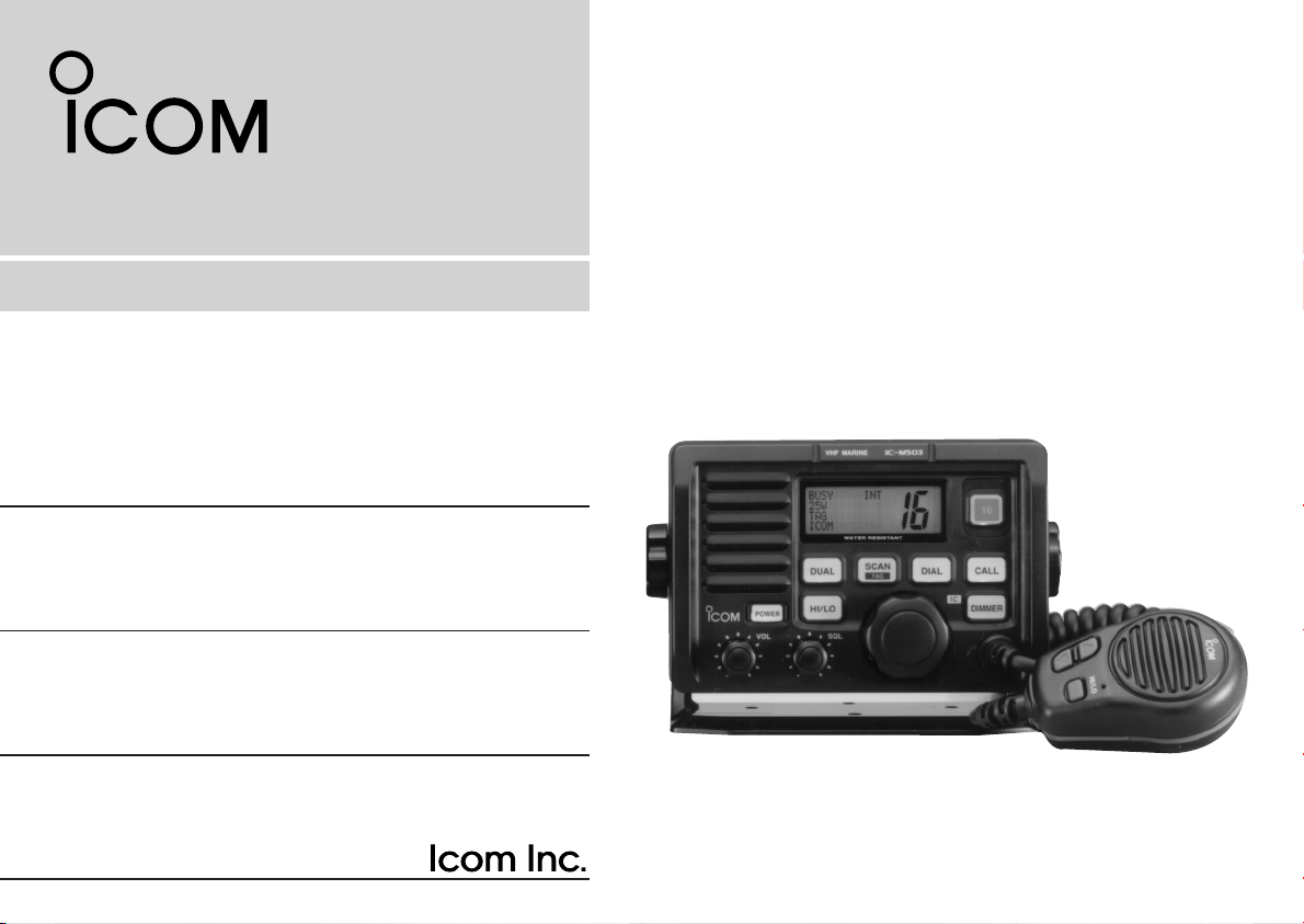
VHF MARINE TRANSCEIVER
iM503
Page 2
IN CASE OF EMERGENCY
If your vessel requires assistance, contact other vessels and
the Coast Guard by sending a distress call on Channel 16.
USING CHANNEL 16
Or, transmit your distress call using digital selective calling on
Channel 70 (the optional DS-100 (#02) must be installed).
USING DIGITAL SELECTIVE CALLING (Ch 70)
(DS-100 (#02) DSC CONTROLLER is required)
DISTRESS CALL PROCEDURE
1. “MAYDAY MAYDAY MAYDAY.”
2. “THIS IS ...............” (name of vessel)
3. Your call sign or other indication of the
vessel (AND 9-digit DSC ID if you have one).
4. “LOCATED AT ...............” (your position)
5. The nature of the distress and assistance
required.
6. Any other information which might facilitate
DISTRESS CALL PROCEDURE
1. Push and hold [DISTRESS] on the DS-100
for 5 sec. until you hear 5 short beeps
change to one long beep.
2. Wait for an acknowledgment from a coast
station.
• Channel 16 is automatically selected.
3. Push and hold [PTT], then transmit the
appropriate information as at left.
the rescue.
Versions of the IC-M503 which display the “CE” symbol on
the serial number seal, comply with the essential requirements of the
European Radio and Telecommunication Terminal Directive
1999/5/EC.
i
This warning symbol indicates that this equipment operates in
non-harmonised frequency bands and/or may be subject to licensing
conditions in the country of use. Be sure to check that you have the
correct version of this radio or the correct programming of this radio,
to comply with national licensing requirements.
Page 3

TABLE OF CONTENTS
IN CASE OF EMERGENCY ........................i
TABLE OF CONTENTS..............................ii
IMPORTANT ..............................................iii
CAUTIONS.................................................iii
1 OPERATING RULES .......................... 1
2 PANEL DESCRIPTION .................. 2 – 5
■ Panel description ............................. 2
■ Function display ............................... 4
■ Microphone ...................................... 5
3 BASIC OPERATION .................... 6 – 10
■ Channel selection ............................ 6
■ Receiving and transmitting .............. 8
■ Call channel programming ............... 9
■ Channel names ................................ 9
■
Optional voice scrambler operation
4 DUALWATCH/TRI-WATCH ............... 11
■ Description ..................................... 11
■ Operation ....................................... 11
5 SCAN OPERATIONS ................. 12 – 13
■ Scan types ..................................... 12
■ Setting tag channels ...................... 13
■ Starting a scan ............................... 13
6 SET MODE ................................. 14– 16
■ Set mode programming ................. 14
■ Set mode items .............................. 15
7 INTERCOM OPERATION ................. 17
■ Intercom operation ......................... 17
.. 10
8 CONNECTIONS AND
MAINTENANCE ......................... 18 – 24
■ Unpacking ...................................... 18
■ Antenna ......................................... 18
■ Fuse replacement .......................... 18
■ Cleaning ......................................... 18
■ Connections ................................... 19
■ Microphone hanger ........................ 20
■ Mounting the transceiver ............... 21
■ Optional unit installation ................. 23
■ Dimensions ..................................... 24
9 TROUBLESHOOTING ...................... 25
10 CHANNEL LIST ................................ 26
11 SPECIFICATIONS AND OPTIONS ... 27
■ Specifications ................................. 27
■ Options .......................................... 27
12 HM-134 REMOTE-CONTROL
MICROPHONE ........................... 28-38
■ Panel description ........................... 28
■ Function display ............................. 30
■ Channel selection .......................... 32
■ Receiving and transmitting ............ 33
■ Lock functions ................................ 34
■ Display backlighting ....................... 34
■ Monitor function ............................. 34
■ Call channel programming ............. 35
■ Optional voice scrambler
operation......................................... 35
■ Starting a scan ............................... 36
■ Setting tag channels ...................... 36
■ Dualwatch/Tri-watch operation ...... 36
■ Set mode programming ................. 37
■ Intercom operation ......................... 38
■ Channel names .............................. 38
13 HM-134 CONNECTIONS AND
INSTALLATION ........................... 39-41
■ HM-134 supplied accessories .........39
■ Installation .......................................39
MB-75 TEMPLATE
INSTALLATION NOTES
ii
Page 4

IMPORTANT
READ ALL INSTRUCTIONS carefully and completely
before using the transceiver.
SAVE THIS INSTRUCTION MANUAL — This in-
struction manual contains important operating instructions for
the IC-M503.
CAUTIONS
RWARNING! NEVER connect the transceiver to an AC
outlet. This may pose a fire hazard or result in an electric
shock.
NEVER connect the transceiver to a power source of more
than 15.6 V DC or using reverse polarity. This will ruin the
transceiver.
NEVER cut the DC power cable between the DC plug and
fuse holder. If an incorrect connection is made after cutting,
the transceiver may be damaged.
NEVER place the transceiver where normal operation of the
vessel may be hindered or where it could cause bodily injury.
KEEP the transceiver at least 1 m away from the ship’s nav-
igation compass.
DO NOT use or place the transceiver in areas with temper-
iii
atures below –20°C or above +60°C or, in areas subject to direct sunlight, such as the cockpit.
AVOID the use of chemical agents such as benzine or al-
cohol when cleaning, as they may damage the transceiver
surfaces.
BE CAREFUL! The transceiver rear panel will become
hot when operating continuously for long periods.
BE CAREFUL! The optional HM-134 remote-control mi-
crophone’s rear panel will become hot when monitoring continuously for long periods.
Place the transceiver in a secure place to avoid inadvertent
use by children.
After exposure to salt water, clean the transceiver thoroughly
with fresh water to avoid corrosion.
Page 5

OPERATING RULES
1
ïï
PRIORITIES
•Read all rules and regulations pertaining to priorities and
keep an up-to-date copy handy. Safety and distress calls
take priority over all others.
•You must monitor Channel 16 when you are not operating
on another channel.
•False or fraudulent distress signals are prohibited and punishable by law.
ïï
PRIVACY
•Information overheard but not intended for you cannot lawfully be used in any way.
• Indecent or profane language is prohibited.
ïï
RADIO LICENSES
(1) SHIP STATION LICENSE
You must have a current radio station license before using the
transceiver. It is unlawful to operate a ship station which is not
licensed.
Inquire through your dealer or the appropriate government
agency for a Ship-Radiotelephone license application. This
government-issued license states the call sign which is your
ship’s identification for radio purposes.
(2) OPERATOR’S LICENSE
A Restricted Radiotelephone Operator Permit is the license
most often held by small ship radio operators when a radio
is not required for safety purposes.
The Restricted Radiotelephone Operator Permit must be
posted or kept with the operator. Only a licensed radio operator may operate a transceiver.
However, non-licensed individuals may talk over a transceiver
if a licensed operator starts, supervises, ends the call and
makes the necessary log entries.
Keep a copy of the current government rules and regulations
handy.
1
Page 6
2
CALLDUAL
SCAN
WATER RESISTANT
TAG
DIAL
DIMMER
HI/LO
POWER
VOL
iM503
VHF MARINE
SQL
16
Speaker
Function
display
q
werty u
io!0!1
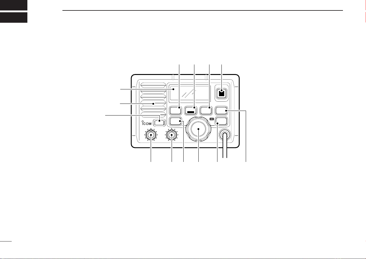
PANEL DESCRIPTION
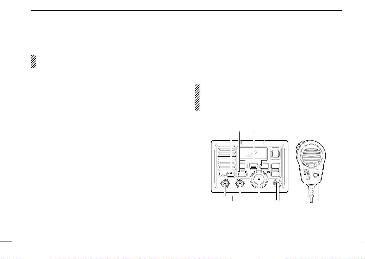
■ Panel description
q POWER SWITCH [POWER]
Push to toggle the transceiver power ON and OFF.
w VOLUME CONTROL [VOL]
Adjusts the audio level. (p. 8)
r TRANSMIT POWER SWITCH [HI/LO]
➥ Push to Toggle high and low power . (p. 8)
• Some channels are set to low power only.
➥ While pushing and holding this switch, other switches
perform secondary functions.
e SQUELCH CONTROL [SQL]
Sets the squelch threshold level. (p. 8)
2
Page 7

PANEL DESCRIPTION
2
t CHANNEL SELECTOR [CHANNEL]
Rotate [CHANNEL] to select the operating channels, set
mode contents, etc. (p. 8)
y DIMMER SWITCH [DIMMER]
➥ Push to select one of 8 backlighting (LCD and switches)
levels.
➥ Push and hold for 1 sec. to turn the intercom mode ON.
u CALL CHANNEL SWITCH [CALL]
➥ Push to select the call channel. (p. 6)
➥ Push and hold for 3 sec. to enter call channel program-
ming condition. (p. 9)
➥ While pushing and holding [HI/LO], enters memory
name programming condition. (p. 9)
i CHANNEL 16 SWITCH [16]
➥ Push to select Channel 16. (p. 6)
➥ While turning power ON, push to enter initial set mode.
(p. 14)
o DIAL SWITCH [DIAL]
➥ Push to exit from Channel 16 or call channel.
(p. 6)
➥ While pushing and holding [HI/LO], push to select chan-
nel group. (pgs. 6, 7)
•The “EUR” version has International channels only and this
function is not available.
!0 SCAN SWITCH [SCAN/TAG] (p. 13)
➥ When tag channels are programmed, starts and stops
normal or priority scan.
➥ Push and hold [SCAN/TAG] for 1 sec. to set the dis-
played channel as a tag (scanned) channel.
➥ While pushing and holding [HI/LO], push and hold for 3
sec. to clear all tag channels.
!1 DUALWATCH/TRI-WATCH SWITCH [DUAL] (p. 11)
➥ Push to start dualwatch or tri-watch.
➥ When dualwatch/tri-watch is activated, push to stop
them.
3
Page 8

INT
CALL
BUSY
25W
TAG SC DUP
CALLING
w
q
e
r
ty
io
u
PANEL DESCRIPTION
2
■ Function display
q BUSY/TRANSMIT INDICATOR (p. 8)
➥ “BUSY” appears when receiving a signal or when the
squelch opens.
➥ “TX” appears while transmitting.
w POWER INDICATOR (p. 8)
➥ “25W” appears when high power is selected.
➥ “1W” appears when low power is selected.
e TAG CHANNEL INDICATOR (p. 13)
Appears when a tag channel is selected.
r CHANNEL NAME INDICATOR
➥ Channel comment appears if programmed. (p. 9)
➥ “Low Battery” appears when the battery voltage drops
4
to approx. 10 V DC or below.
➥ “DUAL” appears during dualwatch; “TRI” appears dur-
ing tri-watch. (p. 11)
➥ “WAIT” appears in the IC-M503 display while transmit-
ting via the HM-134 remote-control microphone.
• In the above case, the connected HM-134 has priority.
➥ “LSTN” appears in the IC-M503 display when pushing
the PTT switch on the HM-134, while the intercom function is activated.
t SCRAMBLER INDICATOR (p. 10)
Appears when the optional voice scrambler is activated.
y DUPLEX INDICATOR
Appears when a duplex channel is selected.
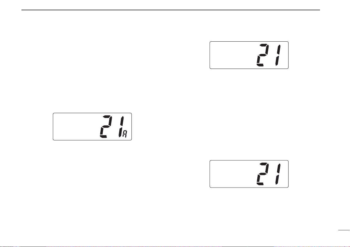
u CHANNEL NUMBER READOUT
➥ Indicates the selected operating channel number. “A”
appears when a simplex channel is selected. (p. 6)
➥ In set mode, indicates the selected condition. (pgs.
15,16)
i CHANNEL GROUP INDICATOR (p. 6)
Indicates whether an International, U.S.A., Holland, DSC
or ATIS channel is selected.
• Available channel groups depend on version.
o CALL CHANNEL INDICATOR (pgs. 6, 9)
Appears when a call channel is selected.
Page 9
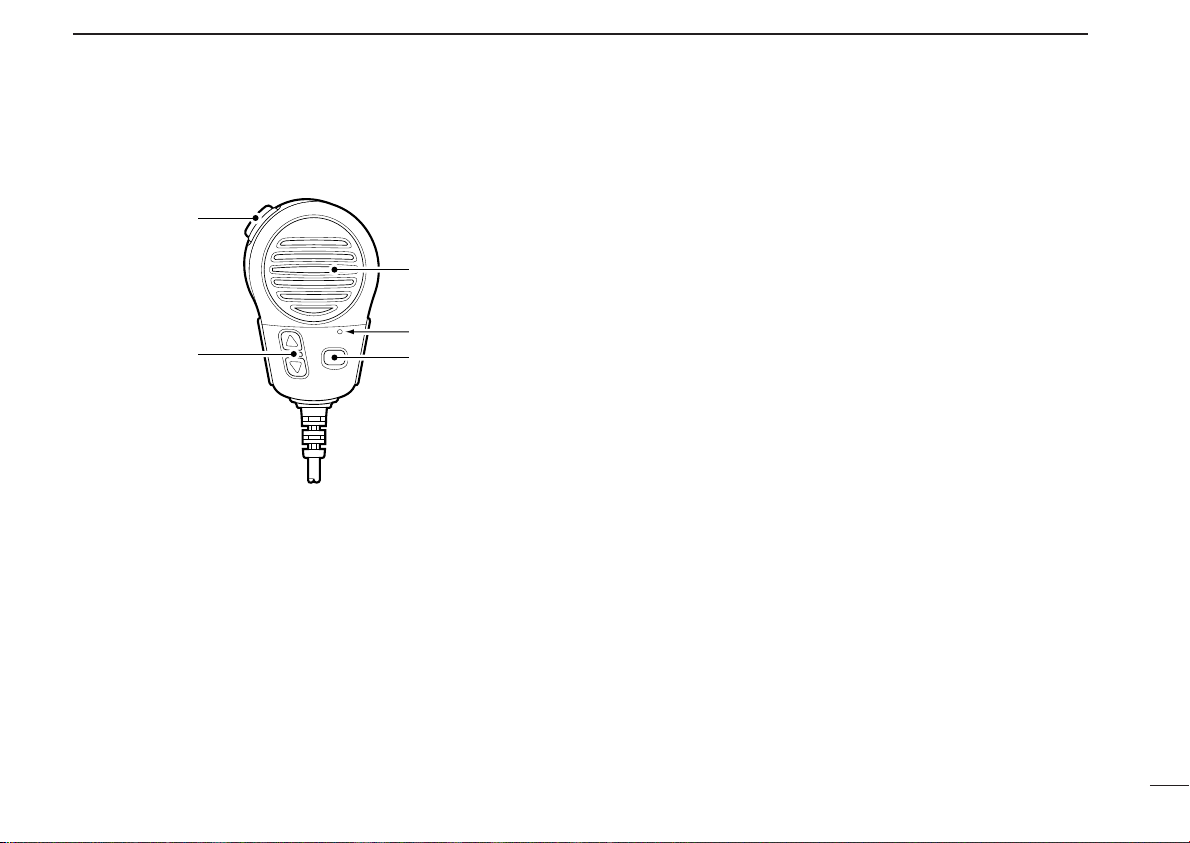
■ Microphone
Speaker
Microphone
w
q
e
q PTT SWITCH [PTT]
Push and hold to transmit; release to receive. (p. 8)
PANEL DESCRIPTION
2
w CHANNEL UP/DOWN SWITCHES [YY]/[ZZ]
Push either switch to change the operating memory channel, set mode contents, etc. (p. 8)
e TRANSMIT POWER SWITCH [HI/LO]
➥ Same as the [HI/LO] switch on the front panel.
➥ When pushed at power ON, toggles the [Y]/[Z] and
[HI/LO] switch functions ON and OFF.
5
Page 10

3
INT
25W
DUPTAG
INTL
Push
CALL
INT
25W CALL
TAG
CALLING
INT
25W
TAG
CALLING
Push
16
BASIC OPERATION
6
■ Channel selection
ïï
Channel 16
Channel 16 is the distress and safety channel. It is used for
establishing initial contact with another station and for emergency communications. Channel 16 is monitored during both
dualwatch and tri-watch. While standing by, you must monitor
Channel 16.
➥ Push [16] to select Channel 16.
•Output power turns to “25W” automatically, whenever Channel
16 is selected. For example, when selecting Channel 16 via the
dial, a scan stops at Channel 16 or [16•C] on the HM-134 is
pushed, etc.
➥ Push [DIAL] to return to the condition before selecting Chan-
nel 16, or rotate [CHANNEL] to select operating channel.
•Output power returns to the previous output power automatically.
ïï
Call channel
Each regular channel group has a separate leisure-use call
channel. The call channel is monitored during tri-watch. The
call channels can be programmed (p. 9) and are used to store
your most often used channels in each channel group for
quick recall.
➥ Push [CALL] to select the call channel of the selected
channel group.
•“CALL” and call channel number appear.
➥ Push [DIAL] to return to the condition before selecting call
channel
ïï
There are 57 International channels for the IC-M503.
q Push [DIAL] to select a regular channel.
w While pushing and holding [HI/LO], push [DIAL]to change
e Rotate the channel selector to select a channel.
, or rotate [CHANNEL] to select operating channel.
International channels
the channel group, if necessary.
•“INT” appears when International channels are selected.
•“DUP” appears for duplex channels.
Page 11
ïï
ATIS
25W
DUPTAG
INTL
HOLLAND
1W
DUP
INTL
USA
25W
TAG
CCG
U.S.A. channels (U.K. version only)
For the U.K. versions, there are 58 U.S.A. channels in addition to 57 International channels.
q Push [DIAL] to select a regular channel.
w While pushing and holding [HI/LO], push [DIAL] to change
the channel group.
• International and U.S.A. channels can be selected in sequence.
e Rotate the channel selector to select a channel.
• Channels are memorized separately for each channel group.
ïï
Holland channels (Holland version only)
For Holland versions, there are 59 Holland channels in addition to 57 International channels.
q Push [DIAL] to select a regular channel.
w While pushing and holding [HI/LO], push [DIAL] to change
the channel group.
•International and Holland channels can be selected in sequence.
e Rotate the channel selector to select a channel.
• Channels are memorized separately for each channel group.
BASIC OPERATION
ïï
ATIS and DSC channels (FRG version only)
For the FRG versions, there are 57 ATIS and 57 DSC channels in addition to 57 International channels.
q Push [DIAL] to select a regular channel.
w While pushing and holding [HI/LO], push [DIAL] to change
the channel group.
•International, ATIS and DSC channels can be selected in sequence.
e Rotate the channel selector to select a channel.
• Channels are memorized separately for each channel group.
3
7
Page 12
16
CALLDUAL
SCAN
WATER RESISTANT
TAG
DIAL
DIMMER
HI/LO
POWER
VOL
iM503
VHF MARINE
SQL
q
w
e
rrt
tyu
BASIC OPERATION
3
■ Receiving and transmitting
CAUTION: Transmitting without an antenna may dam-
age the transceiver.
q Push [POWER] to turn power ON.
w Set the audio and squelch levels.
➥ Rotate [SQL] fully counterclockwise in advance.
➥ Rotate [VOL] to adjust the audio output level.
➥ Rotate [SQL] clockwise until the noise disappears.
e While pushing and holding [HI/LO], push [DIAL] to change
the channel group. (p. 6)
• The European version has International channels only.
r Rotate the channel selector or push [Y]/[Z] on the micro-
phone to select the desired channel.
•When receiving a signal, “BUSY” appears and audio is emitted
from the speaker.
•Further adjustment of [VOL] may be necessary at this point.
•Use the optional voice scrambler function for privacy. (p. 10)
t Push [HI/LO] to select the output power if necessary.
•“25W” or “1W” appears when high or low power is selected, re-
•Choose low power to conserve power, choose high power for
• Some channels are for low power only.
spectively.
longer distance communications.
y Push and hold [PTT] to transmit, then speak into the mi-
crophone.
•“TX” appears.
• Channel 70 cannot be used for transmission (for GMDSS use).
u Release [PTT] to receive.
IMPORTANT: To maximize the readability of your transmitted signal, pause a few sec. after pushing [PTT], hold
the microphone 2 to 5 cm from your mouth and speak at a
normal voice level.
8
Page 13
BASIC OPERATION
INT
25W
TAG
äLEASURE
INT
25W CALL
DUPTAG
INTL
INT
25W CALL
TAG
CALLING
3
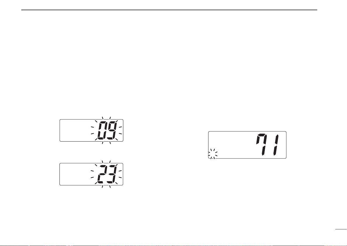
■ Call channel programming
The call channel switch can be programmed to your most
often-used channels in each channel group for quick recall.
q While pushing and holding [HI/LO], push [DIAL] one or
more times to select the desired channel group (International, U.S.A., Holland, ATIS, DSC) to be programmed.
w Push and hold [CALL] for 3 sec. to enter the call channel
programming condition.
• Channel number starts flashing.
e Rotate the channel selector to select the desired channel.
r Push [CALL] to program the displayed channel as the call
channel.
• Push [DIAL] to cancel the programming.
•The channel number stops flashing.
■ Channel names
Memory channels can be tagged with alphanumeric names
of up to 10 characters each.
Capital letters, small letters, numerals, some symbols (! " # $
% & ' ( ) ✱ + ,– . ⁄ ) and spaces can be used.
q Select the desired memory channel.
• Cancel dual watch, tri-watch or scan in advance.
w While pushing and holding [HI/LO], push [CALL] to edit the
memory channel name.
• A cursor appears and blinks.
e Select the desired character by rotating the channel selec-
tor or by pushing [Y]/[Z] on the microphone.
• Push and hold [SCAN] or [DIAL] for cursor movement.
r Push [CALL] to input and set the name.
•The cursor disappears.
t Repeat steps q to r to program another memory channel
name, if desired.
9
Page 14
BASIC OPERATION
Setmode
Beep
Setmode
Scrambler
code
Setmode
Scrambler
code
Enter set mode
16
POWER
+
Select code
16
Push one or
more times.
Set mode Scrambler code item
3
■ Optional voice scrambler operation
10
ïï
Activating the scrambler
The optional voice scrambler provides private communications. In order to receive or send scrambled transmissions
you must first activate the scrambler function. To activate the
function, an optional UT-98 or UT-112 is necessary. See p. 16
for selecting the unit. Ask your dealer for details.
q Select an operating channel other than Channel 16 and
70.
w While pushing and holding [HI/LO], push [DIMMER] to tog-
gle an optional scrambler function ON or OFF.
•“SC” appears.
e To turn the scrambler function OFF, repeat step w.
•“SC” disappears.
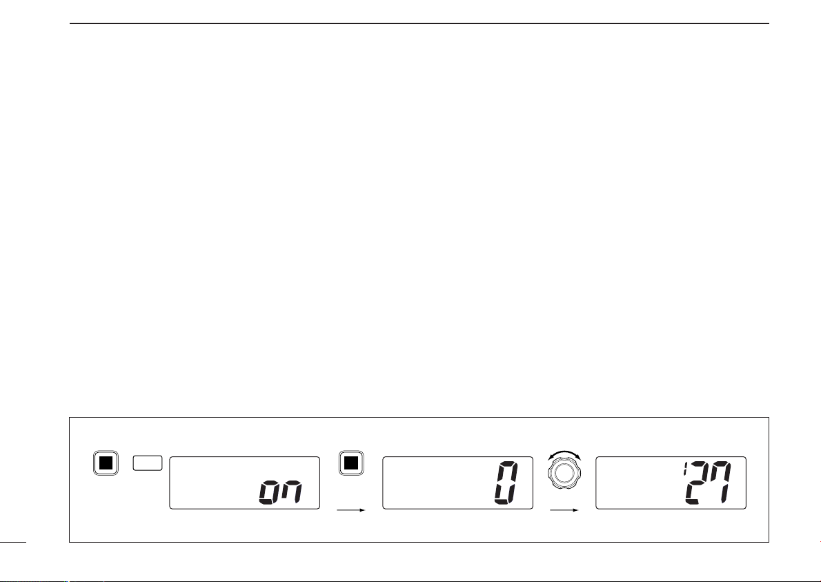
[Example]: Programming scrambler code 127.
ïï
Programming scrambler codes
There are 128 or 32 codes (0 to 127 or 1 to 32) available for
programming. In order to understand one another, all transceivers in your group must have the same scramble code.
This function may not be available depending on dealer setting.
q Turn power OFF.
w While pushing and holding [16], turn power ON to enter
set mode.
e After the display appears, release [16].
r Push [16] one or more times to select the scrambler code
item.
•“Scrambler code” appears.
t Rotate the channel selector to select the desired scram-
bler code.
y Turn power OFF, then ON again to exit set mode.
Page 15
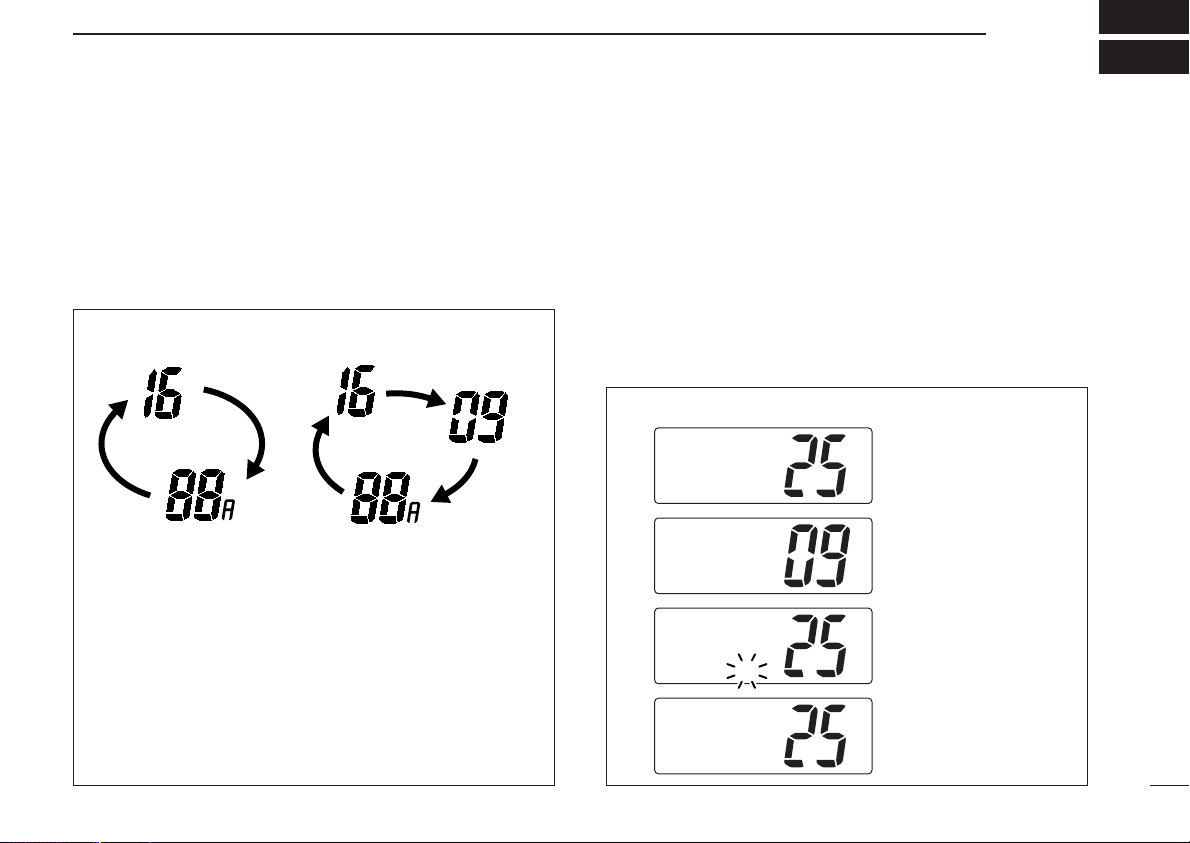
Dualwatch Tri-watch
Call channel
DUALWATCH/TRI-WATCH
4
■ Description
Dualwatch monitors Channel 16 while you are receiving another channel; tri-watch monitors Channel 16 and the call
channel while receiving another channel.
DUALWATCH/TRI-WATCH SIMULATION
•If a signal is received on Channel 16, dualwatch/tri-watch pauses
on Channel 16 until the signal disappears.
•If a signal is received on the call channel during tri-watch, triwatch becomes dualwatch until the signal disappears.
•To transmit on the selected channel during dualwatch/tri-watch,
push and hold [PTT].
■ Operation
q Select the desired operating channel.
w Select dualwatch or tri-watch in set mode. (p. 15)
e Push [DUAL] to start dualwatch or tri-watch.
•“DUAL” appears during dualwatch; “TRI” appears during tri-
watch.
• Beep tone sounds when a signal is received on Channel 16.
•Tri-watch becomes dualwatch when receiving a signal on the call
channel.
r To cancel dualwatch/tri-watch, push [DUAL] again.
[Example]: Operating tri-watch on INT Channel 25.
25W
TAG
TRI
BUSY INT
25W CALL
TAG
CALLING
BUSY INT
25W
TAG
CALLING
25W
TAG
TRI
INT
DUP
16
16
DUP
16
INT
DUP
16
Tri-watch starts.
Signal is received
on call channel.
Signal received on
Channel 16 takes
priority.
Tri-watch resumes
after the signal
disappears.
11
Page 16

5
SCAN OPERATIONS
■ Scan types
Scanning is an efficient way to locate signals quickly over a
wide frequency range. The transceiver has priority scan and
normal scan.
PRIORITY SCAN
CH 01
CH 06
CH 05 CH 04
Priority scan searches through all tag channels in sequence while monitoring Channel 16. When a signal is detected on Channel 16, scan pauses until the signal disappears; when a signal is detected on a channel other than
Channel 16, scan becomes dualwatch until the signal disappears.
CH 16
CH 02
CH 03
Set the tag channels (scanned channel) before scanning.
Clear the tag channels which inconveniently stop scanning,
such as those for digital communication use.
Choose priority scan or normal scan in set mode in advance. (p. 15)
NORMAL SCAN
CH 01 CH 02
CH 06
CH 05 CH 04
Normal scan, like priority scan, searches through all tag
channels in sequence. However, unlike priority scan, Channel 16 is not checked unless Channel 16 is set as a tag
channel.
CH 03
12
Page 17

SCAN OPERATION
INT
25W
DUPTAG
INTL
INT
25W
DUPTAG
Normalscan
BUSY INT
25W
DUPTAG
Normalscan
SCAN
TAG
Push
Scan starts. When a signal is received
5
■ Setting tag channels
For more efficient scanning, add desired channels as tag
channels or clear tag channels that are unwanted channels.
Channels set as non-tag channels will be skipped during
scanning. Tag channels can be assigned to each channel
group (International, U.S.A., Holland, DSC, ATIS) independently.
q While pushing and holding [HI/LO], push [DIAL] one or
more times to select the desired channel group, if desired.
w Select the desired channel to set as a tag channel.
e Push and hold [SCAN/TAG] for 1 sec. to set the displayed
channel as a tag channel.
•“TA G” appears in the function display.
r To cancel the tag channel setting, repeat e.
•“TA G” disappears.
• Clearing all tag channels in the selected channel group
➥ While pushing and holding [HI/LO], push and hold [DIAL]
[Example]: Starting a normal scan.
for 3 sec. to clear all tag channels in the channel group.
■ Starting a scan
Set scan type (priority or normal scan) and scan resume timer
in advance using set mode. (p. 15)
q Set tag channels as described at left.
w While pushing and holding [HI/LO], push [DIAL] one or
more times to select the desired channel group, if desired.
e Push [SCAN] to start priority or normal scan.
•“Pri scan 16” or “Normal scan” appears in the function display.
•When a signal is detected, scan pauses until the signal disap-
pears or resumes after pausing 5 sec. according to set mode setting. (Channel 16 is still monitored during priority scan.)
•Rotate the channel selector to check the scanning tag channels,
to change the scanning direction or resume the scan manually.
•“16” flashes and a beep tone sounds when a signal is received
on Channel 16 during priority scan.
r To stop the scan, push [SCAN].
•“Pri scan” or “Normal scan” disappears.
13
Page 18

6
SET MODE
■ Set mode programming
Set mode is used to change the conditions of the transceiver’s functions: scan mode (normal or priority), scan resume timer, dualwatch/tri-watch selection, beep tone function
(transceiver or HM-134), internal speaker (transceiver or HM-
134), LCD contrast (transceiver or HM-134), scrambler code,
scrambler type and ATIS check.
•Available functions may differ depending on dealer setting.
•The optional HM-134 has it’s own settings for the beep
tone, internal speaker and LCD contrast.
• SET MODE CONSTRUCTION
ATIS check
ATIS check
Scrambler type
Scrambler
type
Scan mode
Scan mode
Push
Scrambler code
Scrambler
code
q Turn power OFF.
w While pushing and holding [16], turn power ON to enter set
mode.
e After the display appears, release [16].
r Push [16] to select the desired item, if necessary.
t Rotate the channel selector to select the desired condition
of the item.
y Turn power OFF, then ON again to exit set mode.
Scan resume timer
Scan timer
16
LCD contrast
LCD
contrast
Dual/tri watch
DUAL/TRI
Beep tone
Beep
Internal speaker
Internal
speaker
14
Page 19

■ Set mode items
Setmode
Beep
Beep tone ON (default) Beep tone OFF
Setmode
DUAL/TRI
Dual watch (default) Tri-watch
Setmode
Scantimer
Scan timer ON (default) Scan timer OFF
Setmode
Scanmode
Priority scan (default) Normal scan
ïï
Scan mode
The transceiver has 2 scan modes: normal scan and priority
scan. Normal scan searches all tag channels in the selected
channel group. Priority scan searches all tag channels in sequence while monitoring channel 16.
ïï
Scan resume timer
The scan resume timer can be selected as a pause (OFF) or
timer scan (ON). When OFF is selected, the scan pauses
until the signal disappears. When ON is selected, the scan
pauses 5 sec. and resumes even if a signal is being received
on channels, except for Channel 16.
SET MODE
ïï
Dual/tri watch
This item sets the [DUAL] switch function as dual watch or triwatch.
See the section ‘Dual watch/Tri-watch’ for details.
ïï
Beep tone
You can select silent operation by turning beep tones OFF or
you can have confirmation beeps sound at the push of a
switch by turning beep* tones ON.
6
*Beep tones setting are selectable on IC-M503 and HM-134 inde-
pendently
15
Page 20

SET MODE
Setmode
ATIScheck
0123456789
ATIS code
Setmode
Scrambler
type
UT-98 scrambler unit UT-112 scrambler unit
Setmode
Scrambler
code
Scrambler code 0 (UT-98 default) Scrambler code 127
Setmode
LCD
contrast
LCD contrast 4 (default)
Setmode
Internal
speaker
Internal speaker ON (default) Internal speaker OFF
6
ïï
Internal speaker
When an optional external speaker is connected, the speakers on the transceiver and microphone can be muted.
*Internal speaker setting is selectable on IC-M503 and HM-134
independently
ïï
LCD contrast
This item adjusts the contrast of the LCD in 8 steps.
*LCD contrast setting is adjustable on IC-M503 and HM-134 in-
dependently
ïï
Scrambler type
When an optional scrambler unit is connected, the scrambler
unit can be selected in set mode depending on dealer setting.
ïï
ATIS check
The ATIS ID code can be checked in set mode.
ïï
Scrambler code
When an optional scrambler unit is connected, the scrambler
16
code can be set depending on dealer setting.
When the UT-98 or UT-112 is installed, 128 or 32 codes (0 to
127 or 1 to 32) can be selected, respectively.
Page 21

■ Intercom operation
Intercom
INT
INT
TALK
IC-M503 (caller) HM-134 (listener)
Intercom
INT
INT
IC-M503 HM-134
The optional intercom function allows you to talk to the deck
from the cabin. The optional HM-134*
CROPHONE
*DO NOT connect another remote-control microphone.
Connect an optional HM-134 as described on p. 39.
• Transmitting is impossible during intercom operation.
• The received signal is muted during intercom operation.
q Push and holding [DIMMER] for 1 sec. to enter intercom
mode.
•The HM-134 power is automatically turned ON, even if the power
w Push and hold [DIMMER] again to call up.
• The transceiver and microphone emit call beeps.
e Push and hold the PTT switch and speak at a normal voice
level into the microphone.
•“TALK” or “LSTN” appears on the caller or listener function dis-
is required for intercom operation.
is OFF.
play, respectively.
REMOTE-CONTROL MI
INTERCOM OPERATION
•To adjust the IC-M503’s speaker output level, rotate [VOL].
-
•To adjust the HM-134’s speaker output level, push [Y]/[Z] after
pushing [VOL].
r After releasing the PTT switch you can hear the response
through the speaker.
t To return to normal operation, push [DIMMER] momentar-
ily.
•Other switches also turn the function OFF, however, the corresponding function is then activated e.g. pushing [16] selects
Channel 16.
•While in the intercom mode, the transceiver functions
(transmit and receive) are interrupted. If the transceiver is
in transmit condition, the intercom function is not available.
7
17
Page 22

8
q
e
w
r
t
y
u
i
o
CONNECTIONS AND MAINTENANCE
■ Unpacking
The following accessories are supplied: Qty.
q Mounting bracket ............................................................ 1
w DC power cable (OPC-891) ........................................... 1
e Microphone hanger ........................................................ 1
r Microphone hanger cable*
(OPC-1096 : Black) ........................................................ 1
t Mounting bracket knobs ................................................. 2
y Microphone hanger screws (3 × 16
u Mounting screws (5 × 20
i Flat washers (M5) ........................................................... 2
o Spring washers (M5) ...................................................... 2
mm) ......................................... 2
mm) ......................... 2
* Depending on version.
■ Antenna
A key element in the performance of any communication system is an antenna. Ask your dealer about antennas and the
best places to mount them.
■ Fuse replacement
Two fuses are installed in the supplied DC power cable. If a
fuse blows or the transceiver stops functioning, track down
the source of the problem, if possible, and replace the damaged fuse with a new, rated one.
■ Cleaning
If the transceiver becomes dusty or dirty, wipe it clean with a
soft, dry cloth.
AVOID the use of solvents such as benzene or alcohol, as they may damage transceiver surfaces.
18
Page 23

CONNECTIONS AND MAINTENANCE
e
q
w
r
t
8
■ Connections
q DC POWER CONNECTOR
Connects the supplied DC power cable from this connector
to an external 12 V DC power source.
CAUTION: After connecting the DC power cable and
external speaker jack, cover the connector and jack as
shown below to avoid water seeping into the transceiver.
w EXTENSION JACK
Connects to the optional DS-100 (#02)
e EXTERNAL MICROPHONE CONNECTOR
Connects to the optional HM-134
PHONE
.
• Intercom function is available.
DSC CONTROLLER.
REMOTE-CONTROL MICRO
CAUTION: NEVER connect another microphone such
as the HM-127, etc. It may cause damage to the transceiver.
r ANTENNA CONNECTOR
Connects a marine VHF antenna with a PL-259 connector
to the transceiver.
CAUTION: Transmitting without an antenna may damage
the transceiver.
t EXTERNAL SPEAKER JACK
Connects to an external speaker. See ‘Options’ on p. 27
for available external speakers.
-
19
Page 24

CONNECTIONS AND MAINTENANCE
OPC-1096
8
■ Microphone hanger
Rest the supplied microphone on the hanger when not in use.
Connect the OPC-1096* to the transceivers chassis and microphone hanger to use the microphone hanger function.
* Depending on version.
• Tighten the screw at fixing torque 0.7 N •m (6.9 kg•m).
• If the microphone hanger function is used, Channel 16 is se-
lected automatically when the supplied microphone is rested
on the hanger.
20
Page 25

CONNECTIONS AND MAINTENANCE
8
■ Mounting the transceiver
ïï
Using the supplied mounting bracket
The universal mounting bracket supplied with your transceiver
allows overhead or dashboard mounting.
•Mount the transceiver securely with the 2 screws supplied
(M5 × 20) to a surface which is more than 10 mm thick and
can support more than 5 kg.
•Mount the transceiver so that the face of the transceiver is at
90° to your line of sight when operating it.
CAUTION: KEEP the transceiver and microphone at
least 1 meter away from your ship’s magnetic navigation
compass.
NOTE: Check the installation angle; the function display
may not be easy-to-read at some angles.
• OVERHEAD MOUNTING
• MOUNTING ON DASHBOARD
21
Page 26

CONNECTIONS AND MAINTENANCE
8
ïï
Using the optional mounting bracket
An optional MB-75 FLUSH MOUNT is available for mounting
the transceiver to a flat surface such as an instrument panel.
CAUTION: KEEP the transceiver and microphone at
least 1 meter away from your ship’s magnetic navigation
compass.
q Using the template on the last page, carefully cut a hole
into the instrument panel (or wherever you plan to mount
the controller).
w Slide the transceiver through the hole as shown below.
e Attach the 2 bolts supplied (M5 × 8 mm) on either side of
the IC-M503.
r Attach the clamps on either side of the transceiver.
• Make sure that the clamps align parallel to the transceiver body.
t Tighten the end bolts on the clamps (rotate clockwise) so
that the clamps press firmly against the inside of the instrument control panel.
y Tighten the locking nuts (rotate counterclockwise) so that
the transceiver is securely mounted in position as below.
u Connect the antenna and control cable, then return the in-
strument control panel to its original place.
22
Page 27

■ Optional unit installation
Optional unit
CONNECTIONS AND MAINTENANCE
8
CAUTION: DISCONNECT the DC power cable from the
transceiver before performing any work on the transceiver.
Otherwise, there is danger of electric shock and/or equipment damage.
ïï
Opening the transceiver case
Follow the case opening procedure shown here when you
want to install an optional unit, etc.
q Remove the 6 screws as shown below and open the trans-
ceiver.
w Remove the 4 screws from the shielding plate, then lift up
the shielding plate.
e Plug an optional unit to the MAIN unit as shown below.
r Return the shielding plate and assemble the units to their
original positions.
23
Page 28

CONNECTIONS AND MAINTENANCE
145.0 (5 23⁄32˝)
165.0 (6
1
⁄2˝)
31.4
(1
1
/4˝)
53.0
(2 3/32˝)
Unit: mm (inch)
110.0 (4
11
⁄32˝) 109.4 (4
5
⁄16˝)
8
■ Dimensions
24
Page 29

TROUBLESHOOTING
PROBLEM POSSIBLE CAUSE SOLUTION REF.
No power comes ON.
•Bad connection to the power supply. •Check the connection to the transceiver. p. 19
9
No sound comes from
the speaker.
Transmitting is impossible, or high power can
not be selected.
Scan does not start. •“TA G ” channel is not programmed. • Set the desired channels as “TAG ” chan-
No beep sounds. • Beep tone is turned OFF. • Turn the beep tone ON in SET mode. p. 15
Receive signal cannot
be understood.
•Squelch level is too deep.
•Volume level is too low.
•Speaker has been exposed to water.
•Some channels are for low power or re-
-
ceive only.
•The output power is set to low.
•Optional voice scrambler is turned OFF.
•Scramble code is not set correctly.
er can
•Set squelch to the threshold point.
•Set [VOL] to a suitable level.
•Drain water from the speaker.
•Change channels.
•Push [HI/LO] to select high power.
nels.
•Turn the optional voice scrambler ON.
•Reset the scramble code.
p. 8
p. 8
—
pgs.
6, 26
p. 8
p. 13
p. 10
p. 16
25
Page 30

26
10
CHANNEL LIST
• International channels
Frequency (MHz)
CH
Transmit Receive Transmit Receive Transmit Receive Transmit Receive Transmit Receive Transmit Receive
01 156.050 160.650 11 156.550 156.550 21 157.050 161.650 62 156.125 160.725 72 156.625 156.625 82 157.125 161.725
02 156.100 160.700 12 156.600 156.600 22 157.100 161.700 63 156.175 160.775 73 156.675 156.675 83 157.175 161.775
03 156.150 160.750 13 156.650 156.650 23 157.150 161.750 64 156.225 160.825 74 156.725 156.725 84 157.225 161.825
04 156.200 160.800 14 156.700 156.700 24 157.200 161.800 65 156.275 160.875 75
05 156.250 160.850 15
06 156.300 156.300 16 156.800 156.800 26 157.300 161.900 67 156.375 156.375 77 156.875 156.875 87 157.375 157.375
07 156.350 160.950 17
08 156.400 156.400 18 156.900 161.500 28 157.400 162.000 69 156.475 156.475 79 156.975 161.575
09 156.450 156.450 19 156.950 161.550 60 156.025 160.625 70
10 156.500 156.500 20 157.000 161.600 61 156.075 160.675 71 156.575 156.575 81 157.075 161.675
Frequency (MHz)
CH
†
156.750 156.750 25 157.250 161.850 66 156.325 160.925 76†156.825 156.825 86 157.325 161.925
†
156.850 156.850 27 157.350 161.950 68 156.425 156.425 78 156.925 161.525 88 157.425 157.425
Frequency (MHz)
CH
Frequency (MHz)
CH
‡
156.525 156.525 80 157.025 161.625
Frequency (MHz)
CH
†
156.775 156.775 85 157.275 161.875
Frequency (MHz)
CH
• USA channels (for U.K. version only)
Frequency (MHz)
CH
Transmit Receive Transmit Receive Transmit Receive Transmit Receive Transmit Receive Transmit Receive
01A 156.050 156.050 12
-- - - - - - - 13
03A 156.150 156.150 14 156.700 156.700 24 157.200 161.800 66A 156.325 156.325
-- - - - - - - 15
05A 156.250 156.250 16 156.800 156.800 26 157.300 161.900 68 156.425 156.425 81A 157.075 157.075 88 157.425 162.025
06 156.300 156.300 17
07A 156.350 156.350 18A 156.900 156.900 28 157.400 162.000 70
08 156.400
09 156.450 156.450 20 157.000 161.600 61A 156.075
10 156.500 156.500 20A 157.000 157.000 -- - - - - - -
11 156.550 156.550 21A 157.050 157.050 63A 156.175 156.175 74
†
Low power only.
156.400 19A 156.950 156.950 37A 157.850 157.850 71 156.575 156.575 84 157.225 161.825
Frequency (MHz)
CH
156.600 156.600 22A 157.100 157.100 64A 156.225 156.225 77 156.875 156.875 86 157.325 161.925
†
156.650 156.650 23A 157.150 157.150 65A
†
156.750 156.750 25 157.250 161.850 67†156.375 156.375 80A 157.025 157.025 87A 157.375 157.375
†
156.850 156.850 27 157.350 161.950 69 156.475 156.475 82A 157.125 157.125 88A 157.425 157.425
‡
Receive only.
Frequency (MHz)
CH
Frequency (MHz)
CH
156.275 156.275 78A 156.925 156.925 86A 157.325 157.325
‡
156.525 156.525 83A 157.175 157.175
156.075 72 156.625 156.625 84A 157.225 157.225
73 156.675 156.675 85 157.275 161.875
156.725 156.725 85A 157.275 157.275
Frequency (MHz)
CH
79A 156.975 156.975 87 157.375 161.975
Frequency (MHz)
CH
Page 31

SPECIFICATIONS AND OPTIONS
11
■ Specifications
• GENERAL
• Frequency coverage :
Transmit 156.000–161.450 MHz
Receive 156.000–163.425 MHz
• Mode : FM (16K0G3E)
• Channel spacing : 25 kHz
• Current drain (at 13.8 V) : TX high 6.0 A max.
Max. audio 1.5 A max.
• Power supply requirement : 13.8 V DC (10.8 to 15.6 V)
• Frequency stability : ±10 ppm (–20°C to +60°C)
•Dimensions : 165(W)×110(H) × 109.4(D) mm
(Projection not included)
• Weight : 1130 g
• TRANSMITTER
• Output power : 25 W and 1 W
• Modulation system : Variable reactance phase
modulation
• Max. frequency deviation : ±5.0 kHz
• Spurious emissions : Less than 0.25 µW
• RECEIVER
• Receive system :
• Sensitivity (20 dB SINAD) : Less than –3dBµ EMF (typical)
• Squelch sensitivity : Less than 0dBµ EMF
•
Intermodulation rejection ratio
•
Spurious response rejection ratio
• Adjacent channel selectivity : More than 70 dB
• Audio output power :
IC-M503 2 W at 10% distortion with a 4 Ω load
HM-134 2 W at 10% distortion with a 8 Ω load
Double conversion superheterodyne
: More than 68 dB
: More than 70 dB
■ Options
• DS-100 (#02)
When the DS-100 is installed, the transceiver conforms to
DSC Class D for marine digital communications.
• MB-75
For mounting the transceiver to a panel.
• HM-134
External microphone-type controller. Provides optional intercom operation. 6 m (20 feet) microphone cable and mounting base included. Black color is available.
• OPC-999
6 m (20 feet) microphone extension cable for optional
HM-134. Up to 2 OPC-999 can be connected. (18 m; 60 feet
maximum)
EXTERNAL SPEAKER
• SP-5
A large, external speaker for superior audio output.
• SP-10
A compact, external speaker. Features easy installation.
• UT-98
• UT-112
Ensures private communications. 128 or 32 codes are
available. Not available in some countries.
All stated specifications are subject to change without notice or
obligation.
DSC CONTROLLER
FLUSH MOUNT
REMOTE-CONTROL MICROPHONE
MICROPHONE EXTENSION CABLE
(IC-M503
EXTERNAL SPEAKER
VOICE SCRAMBLER UNIT
VOICE SCRAMBLER UNIT
(IC-M503
ONLY
ONLY
)
)
27
Page 32

12
DIM
C
MONI
L
IC
q
w
r
e
u
y
t
i
o
!0
DIAL
DUAL
SQL
VOL
!1
To IC-M503
HM-134 REMOTE-CONTROL MICROPHONE
OPTIONAL
■ Panel description
The optional HM-134 remotely controls the IC-M503 and provides an optional intercom function.
q POWER SWITCH [PWR] (pgs. 8, 33)
When the IC-M503 power is turned ON, push and hold for
2 sec. to turn the HM-134 power ON or OFF.
w PTT SWITCH [PTT] (pgs. 8, 33)
Push and hold to transmit; release to receive.
e CHANNEL UP/DOWN SWITCHES [YY]/[ZZ]
➥ Push either switch to change the operating channel, set
mode contents, etc. (pgs. 8, 33)
➥ While pushing and holding [VOL], push [Y]/[Z] to adjust
the brightness of the LCD and switch backlight. (p. 34)
➥ After [VOL] or [SQL] is pushed, push either switch to ad-
just audio level or noise squelch level, respectively. (pgs.
8, 33)
➥ In set mode, changes setting of the selected item. (pgs.
9, 37)
➥ During scanning, checks tag channels or changes scan-
ning direction. (pgs. 8, 36)
r CHANNEL 16/CALL CHANNEL SWITCH [16•C]
➥ When pushed, selects Channel 16. (pgs. 6, 32)
➥ When pushed and held for 1 sec., selects call channel.
(pgs. 6, 32)
•“CALL” appears when call channel is selected.
➥ When call channel is selected, push and hold for 3 sec.
to enter call channel programming condition. (pgs. 9, 35)
➥ While pushing and holding [H/L], enters memory name
programming condition. (pgs. 9, 38)
28
Page 33

HM-134 REMOTE-CONTROL MICROPHONE
12
➥ Enter set mode when pushed and held while turning
power ON. (pgs. 14, 37)
t DIAL SWITCH [DIAL]
➥ Selects and toggles the regular channels when pushed
momentarily. (pgs. 6, 7, 32)
➥ While pushing and holding [H/L], push to select channel
group. (pgs. 6, 7 and 32)
•The “ EUR” version has International channels only and this
function is not available.
y DUAL-WATCH/INTERCOM SWITCH [DUAL•IC]
➥ Push to start dualwatch or tri-watch. (pgs. 11, 36)
➥ Push and hold for 1 sec. to activate the intercom func-
tion. (pgs. 17, 38)
➥ Push to stop dualwatch or tri-watch when either is acti-
vated.
➥ While pushing and holding the switch, you can call the
IC-M503 in intercom mode. (pgs. 17, 38)
u SQUELCH/MONITOR/LOCK SWITCH [SQL•MONI•L]
➥ After pushing [SQL], [Y]/[Z] sets the squelch threshold
level. (p. 33)
➥ Push and hold [SQL•MONI] for 1 sec. to turn the monitor
function ON. (p. 34)
➥ While pushing and holding [H/L], push [SQL•MONI•L] to
toggle the microphone key lock function ON or OFF. (p.
34)
•“ T ” appears while key lock function is in use.
•[PWR], [PTT], [VOL], [SQL] and [H/L] still function when the
microphone key lock function is turned ON.
➥ Advances the cursor while in memory name program-
ming condition. (pgs. 9, 38)
i VOLUME/DIMMER SWITCH [VOL•DIM]
➥ After pushing [VOL], [Y]/[Z] adjusts the audio level.
➥ Push and hold [VOL•DIM] for 1 sec. to adjust the bright-
ness of the LCD and switch backlight. (p. 34)
➥ Moves the cursor backward while in memory name pro-
gramming condition. (pgs. 9, 38)
o TRANSMIT POWER SWITCH [H/L]
➥ When pushed, toggles high and low power. (pgs. 8, 33)
• Some channels are set to low power only.
➥ While pushing and holding this switch, other switches
perform secondary functions.
➥ Toggles the all key lock function ON or OFF when
pushed and held while turning power ON. (p. 34)
•“ T ” flashes while the all key lock function is in use.
•Only [PWR] and [PTT] function when the all key lock function
is in use.
!0 SCAN SWITCH [SCAN•TAG] (pgs. 13, 36)
➥ Starts and stops normal or priority scan when tag chan-
nels are programmed.
➥ Push and hold [SCAN•TAG] for 1 sec. to set the dis-
played channel as a tag (scanned) channel.
➥ While pushing and holding [H/L], push and hold for 3
sec. to clear all tag channels.
29
Page 34

HM-134 REMOTE-CONTROL MICROPHONE
CALL
DUP
P SCAN
SCRM
TRI
DUAL
LOW
TAG
USA
INT
L
TX
BUSY
VOL
SQL
q
w
r
t
e
!6 !5 !2!3 !1
!0
o
i
u
y
!4
WAIT
!7
External SP jack
Connection mold
12
!1 EXTERNAL SPEAKER JACK
➥ Connect the external speaker (
speaker can be deactivated via the Set mode programming. (p. 37)
•The speaker output employs a BTL (Balanced TransLess) circuit, NEVER connect the speaker cable to
ground (or chassis). Use a floating setup.
CAUTION: After connecting the external speaker jack,
cover the jack with water resistant tape as shown below to
avoid water seeping into the microphone.
Binding the mic-cable and external-speaker jack connection mold with water resistant tape increases the waterproofing of the connection mold.
an 8 Ω load)
. The internal
■ Function display
q CHANNEL GROUP INDICATOR (pgs. 6, 32)
Indicates whether an International (INT) or U.S.A. (USA)
channel is selected.
w KEY LOCK INDICATOR (p. 34)
➥ Appears while the key lock function is in use.
➥ Flashes while the all key lock function is in use.
e CHANNEL NUMBER READOUT
➥ Indicates the selected operating channel number. “A”
appears when a simplex channel is selected. (pgs. 6,
32)
30
Page 35

HM-134 REMOTE-CONTROL MICROPHONE
12
➥ In set mode, indicates the selected condition. (pgs. 14,
37)
r VOLUME INDICATOR (p. 33)
Appears while audio output level is adjusted.
t SQUELCH INDICATOR (p. 33)
Appears while noise squelch level is adjusted.
y CHANNEL NAME INDICATOR
➥ Channel comment appears (and scrolls) if programmed.
(pgs. 9, 38)
➥ In set mode, indicates or scrolls the selected set mode
item. (pgs. 14, 37)
u SCRAMBLER INDICATOR (pgs. 10, 35)
Appears when an optional voice scrambler is activated.
i SCAN INDICATOR (pgs. 13, 36)
➥ “SCAN” appears during normal scan.
➥ “P SCAN” appears during priority scan.
o PRIORITY CHANNEL INDICATOR
➥ Indicates a priority channel during priority scan or
dual/tri-watch. (pgs. 12, 36)
➥ “IC” appears during intercom mode. (pgs. 17, 38)
!0 DUAL/TRI WATCH INDICATOR (pgs. 11, 36)
“DUAL” appears during dualwatch; “TRI” during tri-watch.
Appears when low power is selected.
!2 CALL CHANNEL INDICATOR (pgs. 6, 32)
Appears when the call channel is selected.
!3 DUPLEX INDICATOR (pgs. 6, 32)
Appears when a duplex channel is selected.
!4 TAG CHANNEL INDICATOR (pgs. 13, 36)
Appears when a tag channel is selected.
!5 BUSY INDICATOR (pgs. 8, 33, 34)
Appears when receiving a signal or when the squelch
opens.
!6 TRANSMIT INDICATOR (pgs. 8, 33)
Appears while transmitting.
!7 “WAIT” INDICATOR
“WAIT” appears in the HM-134 display while transmitting
via the IC-M503’s attached microphone.
•In the above case, the connected HM-134 does not have priority.
!1 LOW POWER INDICATOR (pgs. 8, 33)
31
Page 36

HM-134 REMOTE-CONTROL MICROPHONE
DIAL
Push and hold
then push
U.S.A. channels
International channels
12
■ Channel selection
ïï
Channel 16
q Push [16•C] to select Channel
16.
w Push [DIAL] to return to the con-
dition before selecting Channel
16, or push [Y] or [Z] to select
operating channel.
•Output power turns to “25W” automatically, whenever Channel 16 is
selected.
ïï
Call channel
q Push and hold [16•C] for 1 sec.
to select call channel.
w Push [DIAL] to return to the con-
dition before selecting call channel, or push [Y] or [Z] to select
operating channel.
ïï
U.S.A. and International channels
q Push [DIAL] to select regular channel.
w While pushing and holding [H/L], push [DIAL] to select
channel group.
•U.S.A. or International can be selected in sequence.
32
Page 37

■ Receiving and transmitting
w Set volume
w Set squelch,
if required
r Set output power
t Speak into
microphone
q Turn power ON
e Set channel
t Push to
transmit
y Release
to receive
HM-134 REMOTE-CONTROL MICROPHONE
12
q Push [PWR] to turn power ON.
w Push [VOL], then [Y]/[Z] to adjust audio output level.
•Push [SQL], then [Y]/[Z] to mute any audio noise, if necessary.
e Push [Y]/[Z] to select the desired channel.
•When receiving a signal, “” appears and audio is emitted
from the speaker.
•Further adjustment of audio level may be necessary at this point.
•Use the optional voice scrambler function for privacy. (pgs. 10,
35)
r Push [H/L] to select the output power, if necessary.
•“LOW” appears when low power is selected.
•Choose low power for shorter, high power for longer distance
communications.
• Some channels are low power only.
t Push and hold [PTT] to transmit, then speak into the mi-
crophone.
•“ ” appears.
•Channel 70 cannot be used for transmission (for GMDSS use).
y Release [PTT] to receive.
IMPORTANT: To maximize the readability of your transmitted signal (voice), pause a few sec. after pushing [PTT],
hold the microphone 10 to 15 cm (4 to 6 inches) from your
mouth and speak at a normal voice level.
33
Page 38

HM-134 REMOTE-CONTROL MICROPHONE
Appears when the lock
function is in use.
Flashes when the all lock
function is in use.
12
■ Lock functions
The lock function electronically locks keys and switches to
prevent accidental changes and function access from the microphone.
• All keys, switches and controllers on the transceiver are functional.
ïï
Activating the lock
function
➥ While pushing and holding
[H/L], push [SQL] to turn the
lock function ON and OFF.
•“ ” appears.
•Only [PWR], [PTT], [H/L],
[SQL•MONI], [VOL]+[Y]/[Z] and
[SQL]+[Y]/[Z] are functional.
ïï
Activating the all key
lock function
➥ While pushing and holding
[H/L], turn the power ON by
pushing [PWR] to turn the all
key lock function ON and OFF.
•“ ” flashes.
•Only [PWR] and [PTT] are func-
tional.
■ Display backlighting
The function display and switches can be backlit for better
visibility under low light conditions. And the backlighting condition can be adjusted independently from the transceiver.
q Push and hold [VOL•DIM] for 1 sec. to enter backlight ad-
justing mode.
•“ ” with number of backlight level appears in the channel name
indicator.
w Push [Y]/[Z] to adjust the backlight level.
•The backlight level is adjustable between 0 (lights OFF) and 3
(brightest).
■ Monitor function
The monitor function releases the noise squelch mute of the
microphone only. (An independent noise squelch system is
employed.)
➥ Push and hold [SQL•MONI] for 1 sec. to activate the mon-
itor function.
•“ ” flashes and audio is emitted.
• Any key, except [Y]/[Z], cancels the monitor function.
34
Page 39

HM-134 REMOTE-CONTROL MICROPHONE
Appears when the voice
scrambler function is in use.
12
■ Call channel programming
q While pushing and holding [H/L],
push [DIAL] several times to select
the desired channel group (USA or
INT) to be programmed.
w Push and hold [16•C] for 1 sec. to
select the call channel of the selected channel group.
•“CALL” and call channel number ap-
pear.
e Push and hold [16•C] again for
3 sec. (until long beep changes to
2 short beeps) to enter call channel
programming condition.
•Call channel number and channel
group to be programmed flashes.
r Push [Y]/[Z] to select the desired
channel.
t Push [16•C] to program the dis-
played channel as the call channel.
•The call channel number and channel
group stop flashing.
■ Optional voice scrambler
operation
ïï
Activating the scrambler
q Select an operating channel, other than Channel 16.
w While pushing and holding
[H/L], push [DUAL] to turn
the voice scrambler function
ON.
•“SCRM” appears.
e To turn the scrambler func-
tion OFF, repeat step w.
•“SCRM” disappears.
ïï
Programming scramble codes
There are 128 codes (00 to 127) available with UT-98 or 32
codes (01 to 32) available with the UT-112 for programming.
In order to understand one another, all transceivers in your
group must have the same scrambler code, as well as the
same scrambler unit. The scrambler code is programmed in
set mode. See pgs. 10, 16, 37 for details.
35
Page 40

HM-134 REMOTE-CONTROL MICROPHONE
12
■ Starting a scan
q While pushing and holding [H/L],
push [DIAL] several times to select
the channel group (USA or INT), if
desired.
w Push [SCAN] to start priority or nor-
mal scan.
•“SCAN” appears during normal scan.
•The priority channel readout indicates
“16”, and “P” and “SCAN” indicators ap-
pear during priority scan.
•When a signal is received, scan pauses
until the signal disappears or resumes
after pausing 5 sec. according to set
mode setting (Channel 16 is still monitored during priority scan).
•Push [Y]/[Z] to check the scanning tag
channels, to change the scanning direction or resume the scan manually.
e To stop the scan, push [SCAN].
•“SCAN” disappears.
•Pushing [PTT], [16•C] or [DIAL] also
stops the scan.
■ Setting tag
channels
q While pushing and holding [H/L],
push [DIAL] several times to select
the channel group (USA and INT), if
desired.
w Push [Y]/[Z] to select the desired
channel to set as a tag channel.
e Push and hold [SCAN•TAG] for
1 sec. to set the displayed channel
as a tag channel.
•“ ” appears.
r To cancel the tag channel setting,
push and hold [SCAN•TAG] for
1 sec.
•“ ” disappears.
• Clearing all tag channels in the
selected channel group
➥ While pushing and holding [H/L],
push [SCAN•TAG] for 3 sec. to clearing all tag channels. (until long beep
changes to 2 short beeps)
■ Dualwatch/Triwatch operation
q Push [Y]/[Z] to select the desired
channel.
•While pushing and holding [H/L], push
[DIAL] several times to select the channel group (USA, INT), if desired.
w Push [DUAL] to start dualwatch or
tri-watch.
•“DUAL” appears during dualwatch; “TRI”
appears during tri-watch.
•Beep tone sounds when a signal is received on Channel 16.
•Tri-watch becomes dualwatch when receiving a signal on the call channel.
e To cancel dualwatch/tri-watch, push
[DIAL] again.
36
Page 41

HM-134 REMOTE-CONTROL MICROPHONE
Push
• •
• •
Push
Push
12
■ Set mode programming
Set mode is used to change the condition of the transceiver’s
functions and the microphone’s own functions:
Transceiver’s functions—
Scan mode (normal or priority), scan resume timer, dualwatch/tri-watch selection, beep tone function, internal
speaker, LCD contrast, scrambler code, scrambler type and
ATIS check.
Microphone’s own functions—
Beep tone function, LCD contrast and internal speaker.
In this section, instructions are for the microphone’s own functions only. Refer to pgs. 14–16 for the setting of the other
functions. (Some functions may not be selectable from the microphone.)
ïï
Entering set mode
q Turn power OFF.
w While pushing and holding [16•C], turn power ON.
•After beep emission, a set mode item (in the channel name indicator and condition in the channel number readout) is displayed.
e Push [16•C] to select the desired item, if necessary.
r Push [Y]/[Z] to select the desired condition of the item.
t Turn power OFF, then ON to exit set mode.
• Beep tone “BEEP”
➥ Push [Y] to turn ON, [Z] to turn OFF the beep output.
• LCD contrast “LCD CONTRAST”
➥ Push [Y]/[Z] to adjust to a suitable LCD contrast.
• Internal speaker “INT-SPEAKER”
➥ Push [Y]/[Z] to turn the HM-134 internal-speaker ON/OFF.
37
Page 42

HM-134 REMOTE-CONTROL MICROPHONE
(r)
(s) (t) (u) (v) (w) (x) (y) (z)
(q)
(3)
(D)
(N)
(X)
(h)
(+)
(4)
(E)
(O)
(Y)
(i)
(–)
(5)
(F)
(P)
(Z)
(j)
(✱)
(6)
(G)
(Q)
(a)
(k)
(/)
(7)
(H)
(R)
(b)
(l)
(,)
(8)
(I)
(S)
(c)
(m)
(space)
(9)
(T)
(d)
(n)
(0)
(A)
(U)
(e)
(o)
(1)
(B)
(V)
(f)
(p)
(2)
(C)
(J) (K) (L)
(M)
(W)
(g)
(.)
( ))(( )(’)(&)(%)($)(#)(")(!)
Appears when the intercom function is in use.
12
■ Intercom operation
q Push and hold [DUAL] for 1 sec.
to activate the intercom function.
•“IC” appears in the priority channel
readout.
•The channel name disappears.
w Push [PTT] to talk.
•“ ” appears in the channel
name indicator.
e Release [PTT] to listen.
•“ ” appears in the channel name indicator when the transceiver is in talking mode.
r Push [DUAL] to cancel the intercom function.
•Pushing [16], [SCAN•TAG] or [DIAL] is also cancels the intercom
function.
For your reference:
In case the intercom mode is selected with the transceiver
during microphone power OFF, the microphone power is automatically turned ON and the intercom mode is selected.
ïï
Intercom beep function
➥ Push and hold [DIAL] for more than 1 sec.
• Emits intercom beep while holding.
■ Channel names
q Push [Y]/[Z] to select a channel to program.
•While pushing and holding [H/L], push [DIAL] several times to
select the channel group (USA and INT), if desired.
w While pushing and holding [H/L], push [16•C].
•The 1st character of the currently programmed comment flashes.
e Push [Y]/[Z] to select a character.
r Push [SQL] to move to right; then push [Y]/[Z] to select a
character.
• Push [VOL] to move to the left.
t Continue until the desired characters have been selected,
then push [16•C] to return to normal operation.
• Available characters
38
Page 43

HM-134 CONNECTIONS AND INSTALLATION
q
we
r
13
■ HM-134 supplied accessories
Accessories included with the HM-134: Qty.
q Connection cable (OPC-1000: 6 m; 20 ft) ...................... 1
w Mounting base ................................................................ 1
e Microphone hanger ........................................................ 1
r Screws (M3 × 16; tapping) ............................................. 5
■ Installation
The optional HM-134 can be connected to the transceiver directly, as well as via the supplied connection cable for longer
distance remote operation. The connector of the connection
cable can be installed into a cabinet, wall, etc., as a built-in
plug.
For longer distance remote operation, the optional extension
cable, OPC-999 (6 m; 20 ft/Connecting between transceiver
and the connection cable.), is available, and up to 2 OPC-999
can be added.
q Insert the supplied cable into the external microphone jack
and tighten the cable nut as shown below.
39
Page 44

HM-134 CONNECTIONS AND INSTALLATION
Gasket
Cap
Mounting base Nut
Screw holes
(approx. 2 (d) mm; 3⁄32″)
13
w To use the supplied cable as a wall socket, see the follow-
ing steps.
e Using the mounting base, carefully mark off the 2 spots
where the cable and screws will be fastened.
r Drill holes at these marks.
t Install the mounting base using screws as shown below.
y The installation is completed.
40
Page 45

HM-134 CONNECTIONS AND INSTALLATION
50 (d) mm; 1
31
⁄32˝
23 (d) mm;
29
⁄32˝
24 to 27 (d) mm
(
15
⁄16 to 1
1
⁄16˝)
5 mm; 3⁄16˝
Gasket
Mounting base
Cap
Nut
2 mm; 3⁄32˝
2 mm; 3⁄32˝ x 3
24 to 27 (d) mm
(
15
⁄16 to 11⁄16˝)
13
41
Page 46

149 (57⁄8˝)
MB-75 TEMPLATE
Cut here
MB-75
HM-134
24 to 27 (d) mm
15
(
⁄16 to 11⁄16˝)
2 mm;
3
⁄32˝
4–R11
Unit: mm (inch)
˝)
8
⁄
5
92 (3
Page 47

■ Installation notes
INSTALLATION NOTES
The installation of this equipment should be made in such a
manner as to respect the EC recommended electromagnetic
field exposure limits (1999/519/EC).
The maximum RF power available from this device is 25
watts. The antenna should be installed as high as possible
for maximum efficiency and that this installation height should
be at least 5 meters above ground (or accessible) level. In the
case where an antenna cannot be installed at a reasonable
height, then the transmitter should neither be continuously operated for long periods if any person is within 5 meters of the
antenna, nor operated at all if any person is touching the antenna.
In all cases any possible risk depends on the transmitter
being activated for long periods. (actual recommendation limits are specified as an average of 6 minutes) Normally the
transmitter is not active for long periods of time. Some radio licenses will require that a timer circuit automatically cuts the
transmitter after 1–2 minutes etc.
Similarly some types of transmitter, SSB, CW, AM, etc. have a
lower ‘average’ output power and the perceived risk is even
lower.
Page 48

DECLARATION
OF CONFORMITY
We Icom Inc. Japan
1-1-32 Kamiminami, Hirano-ku,
Osaka 547-0003 Japan
Kind of equipment:
VHF MARINE TRANSCEIVER
This compliance is based on conformity with the following harmonised
standards, specifications or documents:
i)
EN 301 025-1 V1.1.2 (2000-08)
ii)
EN 301 025-2 V1.1.1 (2000-08)
iii)
EN 301 025-3 V1.1.1 (2001-05)
iv) EN 300 162-2 V1.1.2 (2000-12)
v) EN 300 162-3 V1.1.1 (2001-05)
vi) EN 60945 1997
vii) EN 60950 1992
viii) EN 300 698-2 V1.1.1 ( 2000-8)
Type-designation: iC-
m503
Authorized representative name
Place and date of issue
Icom (Europe) GmbH
Himmelgeister straße 100
D-40225 Düsseldorf
Düsseldorf 25th Sept. 2001
Declare on our sole responsibility that this equipment complies with the
essential requirements of the Radio and Telecommunications Terminal
Equipment Directive, 1999/5/EC, and that any applicable Essential Test
Suite measurements have been performed.
Version (where applicable):
0560
Signature
T. Maebayashi
General Manager
Page 49

< Intended Country of Use >
GER
AUT
GBR
IRL
FRA
NED
BEL
LUX
ESP
POR
ITA
GRE
SWE
DEN
FIN
SUI
Count on us!
A-6097D-1EU-q
Printed in Japan
© 2001 Icom Inc.
1-1-32 Kamiminami, Hirano-ku, Osaka 547-0003 Japan
Page 50

AA
10
CHANNEL LIST
• International channels
Frequency (MHz)
CH
Transmit Receive Transmit Receive Transmit Receive Transmit Receive Transmit Receive Transmit Receive
01 156.050 160.650 11 156.550 156.550 21 157.050 161.650 62 156.125 160.725 72 156.625 156.625 82 157.125 161.725
02 156.100 160.700 12 156.600 156.600 22 157.100 161.700 63 156.175 160.775 73 156.675 156.675 83 157.175 161.775
03 156.150 160.750 13 156.650 156.650 23 157.150 161.750 64 156.225 160.825 74 156.725 156.725 84 157.225 161.825
04 156.200 160.800 14 156.700 156.700 24 157.200 161.800 65 156.275 160.875 75†156.775 156.775 85 157.275 161.875
05 156.250 160.850 15†156.750 156.750 25 157.250 161.850 66 156.325 160.925 76†156.825 156.825 86 157.325 161.925
06 156.300 156.300 16 156.800 156.800 26 157.300 161.900 67 156.375 156.375 77 156.875 156.875 87 157.375 157.375
07 156.350 160.950 17
08 156.400 156.400 18 156.900 161.500 28 157.400 162.000 69 156.475 156.475 79 156.975 161.575
09 156.450 156.450 19 156.950 161.550 60 156.025 160.625 70‡156.525 156.525 80 157.025 161.625
10 156.500 156.500 20 157.000 161.600 61 156.075 160.675 71 156.575 156.575 81 157.075 161.675
Frequency (MHz)
CH
†
156.850 156.850 27 157.350 161.950 68 156.425 156.425 78 156.925 161.525 88 157.425 157.425
Frequency (MHz)
CH
Frequency (MHz)
CH
Frequency (MHz)
CH
Frequency (MHz)
CH
• USA channels (for U.K. version only)
Frequency (MHz)
CH
Transmit Receive Transmit Receive Transmit Receive Transmit Receive Transmit Receive Transmit Receive
01A 156.050 156.050 12 156.600 156.600 22A 157.100 157.100 64A 156.225 156.225 77 156.875 156.875 86 157.325 161.925
-- - - - - - - 13†156.650 156.650 23A 157.150 157.150 65A 156.275 156.275 78A 156.925 156.925 86A 157.325 157.325
03A 156.150 156.150 14 156.700 156.700 24 157.200 161.800 66A 156.325 156.325 79A 156.975 156.975 87 157.375 161.975
-- - - - - - - 15†156.750 156.750 25 157.250 161.850 67†156.375 156.375 80A 157.025 157.025 87A 157.375 157.375
05A 156.250 156.250 16 156.800 156.800 26 157.300 161.900 68 156.425 156.425 81A 157.075 157.075 88 157.425 162.025
06 156.300 156.300 17
07A 156.350 156.350 18A 156.900 156.900 28 157.400 162.000 70‡156.525 156.525 83A 157.175 157.175
08 156.400 156.400 19A 156.950 156.950 37A 157.850 157.850 71 156.575 156.575 84 157.225 161.825
09 156.450 156.450 20 157.000 161.600 61A 156.075 156.075 72 156.625 156.625 84A 157.225 157.225
10 156.500 156.500 20A 157.000 157.000 -- - - - - - - 73 156.675 156.675 85 157.275 161.875
11 156.550 156.550 21A 157.050 157.050 63A 156.175 156.175 74 156.725 156.725 85A 157.275 157.275
†
Low power only.
Frequency (MHz)
CH
†
156.850 156.850 27 157.350 161.950 69 156.475 156.475 82A 157.125 157.125 88A 157.425 157.425
‡
Receive only.
Frequency (MHz)
CH
Frequency (MHz)
CH
Frequency (MHz)
CH
Frequency (MHz)
CH
 Loading...