

Page 1
INSTRUCTION MANUAL
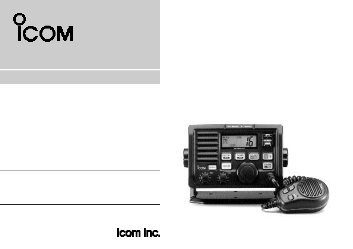
VHF MARINE TRANSCEIVER
iM502
This device complies with Part 15 of the FCC rules. Operation is subject to the following two conditions: (1) This device may not cause
harmful interference, and (2) this device must accept any interference
received, including interference that may cause undesired operation.
Page 2

IMPORTANT
READ ALL INSTRUCTIONS carefully and completely
before using the transceiver.
IN CASE OF EMERGENCY
If your vessel requires assistance, contact other vessels and
the Coast Guard by sending a distress call on channel 16.
USING CHANNEL 16
DISTRESS CALL PROCEDURE
1. “MAYDAY MAYDAY MAYDAY.”
2. “THIS IS ...............” (name of vessel)
3. Your call sign or other indication of the vessel
(AND 9-digit DSC ID if you have one).
4. “LOCATED AT ...............” (your position)
5. The kind of the distress and assistance
required.
6. Any other information which might facilitate
the rescue.
SAVE THIS INSTRUCTION MANUAL — This in-
struction manual contains important operating instructions for
the IC-M502.
Or, transmit your distress call using digital selective calling on
channel 70.
USING DIGITAL SELECTIVE CALLING
(Ch 70)
DISTRESS CALL PROCEDURE
1. While lifting up the switch cover, push and
hold [DISTRESS] for 5 sec. until you hear 5
short beeps change to one long beep.
2. Wait for an acknowledgment from a coast
station.
• Channel 16 is automatically selected.
3. Push and hold [PTT], then transmit the
appropriate information as at left.
i
Page 3

TABLE OF CONTENTS
IMPORTANT .............................................. i
IN CASE OF EMERGENCY ...................... i
TABLE OF CONTENTS ............................ ii
CAUTIONS ............................................... iii
1 OPERATING RULES .................. 1
2 PANEL DESCRIPTION .......... 2– 5
■ Panel description ............................ 2
■ Function display .............................. 4
■ Microphone ..................................... 5
3 BASIC OPERATION ............ 6 – 10
■ Channel selection ........................... 6
■ Microphone lock function ................ 7
■ Receiving and transmitting ............. 8
■ Call channel programming .............. 9
■ Channel names .............................. 9
■ Optional voice scrambler
operation ....................................... 10
4 DUALWATCH/TRI-WATCH ....... 11
■ Description .................................... 11
■ Operation ...................................... 11
5 SCAN OPERATIONS ......... 12 – 13
■ Scan types .................................... 12
■ Setting tag channels ..................... 13
■ Starting a scan .............................. 13
6 DSC OPERATION .............. 14 – 28
■ MMSI code programming ............. 14
■ Position and time programming .... 14
■ Position indication ......................... 15
■ Distress call .................................. 16
■ Transmitting DSC calls ................. 17
■ Setting the distress information .... 21
■ DSC individual ID ......................... 22
■ Receiving DSC calls ..................... 23
■ DSC set mode .............................. 26
■ Receive messages ....................... 28
7 INTERCOM OPERATION ......... 29
■ Intercom operation ........................ 29
8 SET MODE ........................ 30– 33
■ Set mode programming ................ 30
■ Set mode items ............................. 31
9 CONNECTIONS AND
MAINTENANCE ................. 34– 39
■ Supplied accessories .................... 34
■ Antenna ........................................ 34
■ Fuse replacement ......................... 34
■ Cleaning ....................................... 34
■ Connections .................................. 35
■ Mounting the transceiver .............. 36
■ Optional unit installation ............... 38
■ Dimensions.................................... 39
10 TROUBLESHOOTING .............. 40
11 CHANNEL LIST ........................ 41
12 SPECIFICATIONS AND
OPTIONS ........................... 42 – 43
■ Specifications ............................... 42
■ Options ......................................... 43
13 HM-127 REMOTE-CONTROL
MICROPHONE ................... 44 – 56
■ Panel description .......................... 44
■ Function display ............................ 46
■ HM-127 supplied accessories ...... 47
■ Installation .................................... 48
■ Channel selection ......................... 50
■ Receiving and transmitting ........... 51
■ RF attenuator function .................. 51
■ Lock functions ............................... 52
■ Display backlighting ...................... 52
■ Monitor function ............................ 52
■ Call channel programming ............ 53
■ Optional voice scrambler
operation ....................................... 53
■ Starting a scan .............................. 54
■ Setting tag channels ..................... 54
■ Dualwatch/Tri-watch operation ..... 54
■ Set mode programming ................ 55
■ Intercom operation ........................ 56
■ Channel names ............................ 56
TEMPLATE
ii
Page 4

CAUTIONS
RWARNING! NEVER connect the transceiver to an AC
outlet. This may pose a fire hazard or result in an electric
shock.
CAUTION: Changes or modifications to this device, not ex-
pressly approved by Icom Inc., could void your authority to
operate this device under FCC regulations.
NEVER connect the transceiver to a power source of more
than 16 V DC or use reverse polarity. This will ruin the transceiver.
NEVER cut the DC power cable between the DC plug and
fuse holder. If an incorrect connection is made after cutting,
the transceiver may be damaged.
NEVER place the transceiver where normal operation of the
vehicle may be hindered or where it could cause bodily injury.
KEEP the transceiver at least 3.3 ft (1 m) away from the
ship’s navigation compass.
DO NOT use or place the transceiver in areas with temper-
atures below –4°F (–20°C) or above +140°F (+60°C) or, in
areas subject to direct sunlight, such as the dashboard.
AVOID the use of chemical agents such as benzine or al-
cohol when cleaning, as they may damage the transceiver
surfaces.
BE CAREFUL! The transceiver rear panel will become
hot when operating continuously for long periods.
Place the transceiver in a secure place to avoid inadvertent
use by children.
BE CAREFUL! The transceiver and optional HM-127 em-
ploy waterproof construction, which corresponds to JIS waterproof specification, grade 7 (1 m/30 min.). However, once
the transceiver or microphone has been dropped, waterproofing cannot be guaranteed due to the fact that the case
may be cracked, or the waterproof seal damaged, etc.
CLEAN THE TRANSCEIVER AND MICROPHONE
THOROUGHLY WITH FRESH WATER after exposure to
water including fresh water, otherwise, the keys and
iii
Page 5

OPERATING RULES
1
PRIORITIES
•Read all rules and regulations pertaining to priorities and
keep an up-to-date copy handy. Safety and distress calls
take priority over all others.
• You must monitor channel 16 when you are not operating on
another channel.
•False or fraudulent distress signals are prohibited and punishable by law.
PRIVACY
•Information overheard but not intended for you cannot lawfully be used in any way.
• Indecent or profane language is prohibited.
RADIO LICENSES
(1) SHIP STATION LICENSE
You must have a current radio station license before using the
transceiver. It is unlawful to operate a ship station which is not
licensed.
Inquire through your dealer or the appropriate government
agency for a Ship-Radiotelephone license application. This
government-issued license states the call sign which is your
craft’s identification for radio purposes.
(2) OPERATOR’S LICENSE
A Restricted Radiotelephone Operator Permit is the license
most often held by small vessel radio operators when a radio
is not required for safety purposes.
The Restricted Radiotelephone Operator Permit must be
posted or kept with the operator. Only a licensed radio operator may operate a transceiver.
However, non-licensed individuals may talk over a transceiver
if a licensed operator starts, supervises, ends the call and
makes the necessary log entries.
Keep a copy of the current government rules and regulations
handy.
Radio license for boaters (U.S.A. only)
The Telecommunications Act of 1996 permits recreational
boaters to have and use a VHF marine radio, EPIRB, and
marine radar without having an FCC ship station license.
Boaters traveling on international voyages, having an HF
single sideband radiotelephone or marine satellite terminal,
or required to carry a marine radio under any other regulation must still carry an FCC ship station license. For further
information, see the FCC Ship Radio Stations Fact Sheet.
1
Page 6
2
PANEL DESCRIPTION
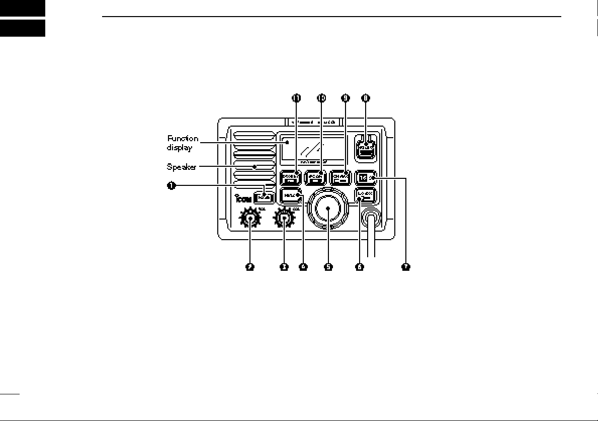
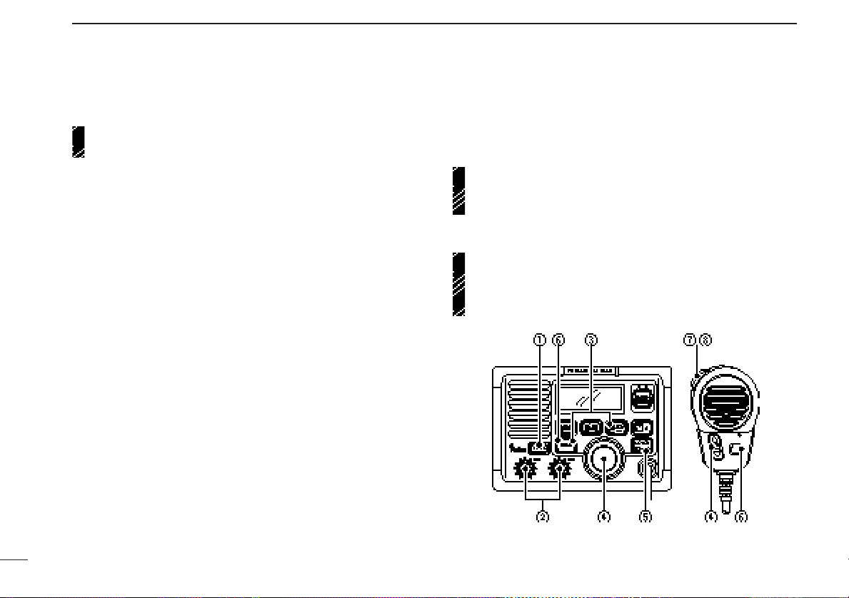
■ Panel description
q POWER SWITCH [POWER]
Push to toggle the transceiver power ON and OFF.
w VOLUME CONTROL [VOL]
Adjusts the audio level. (p. 8)
e SQUELCH CONTROL [SQL]
Sets the squelch threshold level. (p. 8)
2
r TRANSMIT POWER SWITCH [HI/LO]
➥ Toggles high and low power when pushed. (p. 8)
• Some channels are set to low power only.
➥ While pushing this switch, other switches perform sec-
ondary functions.
t CHANNEL SELECTOR [CHANNEL]
➥ Rotate [CHANNEL] to select the operating channels, set
mode contents, etc. (p. 8)
Page 7

PANEL DESCRIPTION
2
➥ While pushing [HI/LO], rotate [CHANNEL] to adjust the
brightness of the LCD and switch backlight.
y ATTENUATOR/INTERCOM/SCRAMBLER SWITCH
[LO/DX•IC•SCR]
➥ Toggles the attenuator function ON and OFF when
pushed momentarily. (p. 8)
•“LOCAL” appears when the attenuator is in use. The order of
indication precedence is “LOCAL,” “SP OFF” and “CALL.”
➥ Activates an optional intercom function when pushed for
1 sec. (p. 29)
➥ Calls optional HM-127
when pushed and held while in intercom mode. (p. 29)
➥ While pushing [HI/LO], activates an optional voice
scrambler function. (p. 10)
•The optional voice scrambler function cannot be used on
channel 16 and 70.
u CHANNEL 16/CALL CHANNEL SWITCH [16•9]
➥ Selects channel 16 when pushed. (p. 6)
➥ Selects call channel when pushed for 1 sec. (p. 6)
•“CALL” appears when call channel is selected. “LOCAL” and
“SP OFF” indications have priority.
➥ Push for 3 sec. to enter call channel programming con-
dition when call channel is selected. (p. 9)
➥ While pushing [HI/LO], enters memory name program-
ming condition. (p. 9)
➥ Enters set mode when pushed while turning power ON.
(p. 30)
REMOTE-CONTROL MICROPHONE
i DISTRESS SWITCH [DISTRESS]
Transmits distress call when pushed for 5 sec. (p. 16)
o CHANNEL/DUALWATCH/TRI-WATCH SWITCH
[CH/WX•DW•U/I/C]
➥ Selects and toggles the regular channels and weather
channel when pushed momentarily. (pgs. 6, 7)
➥ While pushing [HI/LO], selects one of 3 regular channels
in sequence when pushed. (pgs. 6, 7)
•International, U.S.A. and Canadian channels are available for
regular channels.
➥ Starts dualwatch or tri-watch when pushed for 1 sec.
(p. 11)
➥ Stops dualwatch or tri-watch when either is activated.
!0 SCAN SWITCH [SCAN•TAG] (p. 13)
➥ Starts and stops normal or priority scan when tag chan-
nels are programmed.
➥ Push [SCAN•TAG] for 1 sec. to set the displayed chan-
nel as a tag (scanned) channel.
➥ While pushing [HI/LO], push for 3 sec. to clear all tag
channels.
!1 DSC/POSITION SWITCH [DSC/ENT•POS]
➥ Selects the DSC menu when pushed. (p. 14)
➥ Shows current position and time from an optional GPS
receiver, etc. when pushed for 1 sec. (p. 15)
3
Page 8

PANEL DESCRIPTION
2
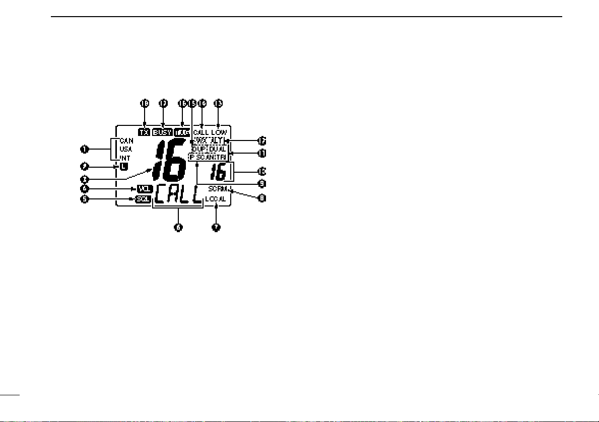
■ Function display
q BUSY/TRANSMIT INDICATOR (p. 8)
➥ “BUSY” appears when receiving a signal or when the
squelch opens.
➥ “TX” appears while transmitting.
w POWER INDICATOR (p. 8)
➥ “25W” appears when high power is selected.
➥ “1W” appears when low power is selected.
e TAG CHANNEL INDICATOR (p. 13)
Appears when a tag channel is selected.
r CHANNEL NAME INDICATOR
➥ Channel comment appears if programmed. (p. 9)
➥ “Low battery” flashes when the battery voltage drops to
approx. 10 V DC or below.
➥ “DUAL” appears during dualwatch; “TRI” appears dur-
ing tri-watch. (p. 11)
t SCRAMBLER INDICATOR (p. 10)
Appears when an optional voice scrambler is activated.
y DUPLEX INDICATOR (p. 6)
Appears when a duplex channel is selected.
u CHANNEL NUMBER READOUT
➥ Indicates the selected operating channel number. “A”
appears when a simplex channel is selected. (p. 6)
➥ In set mode, indicates the selected condition. (p. 30)
i CHANNEL GROUP INDICATOR (p. 6)
Indicates whether an International (INT), U.S.A. (USA),
Canadian (CANADA) or weather (WX) channel is selected.
o CALL CHANNEL INDICATOR
➥ “CALL” appears when the call channel is selected. (p.
6)
➥ “SP OFF” appears when the internal speaker is turned
OFF in set mode. (p. 32)
➥ “LOCAL” appears when the attenuator is in use. (p. 8)
•The order of indication precedence is “LOCAL,” “SP OFF” and
4
Page 9
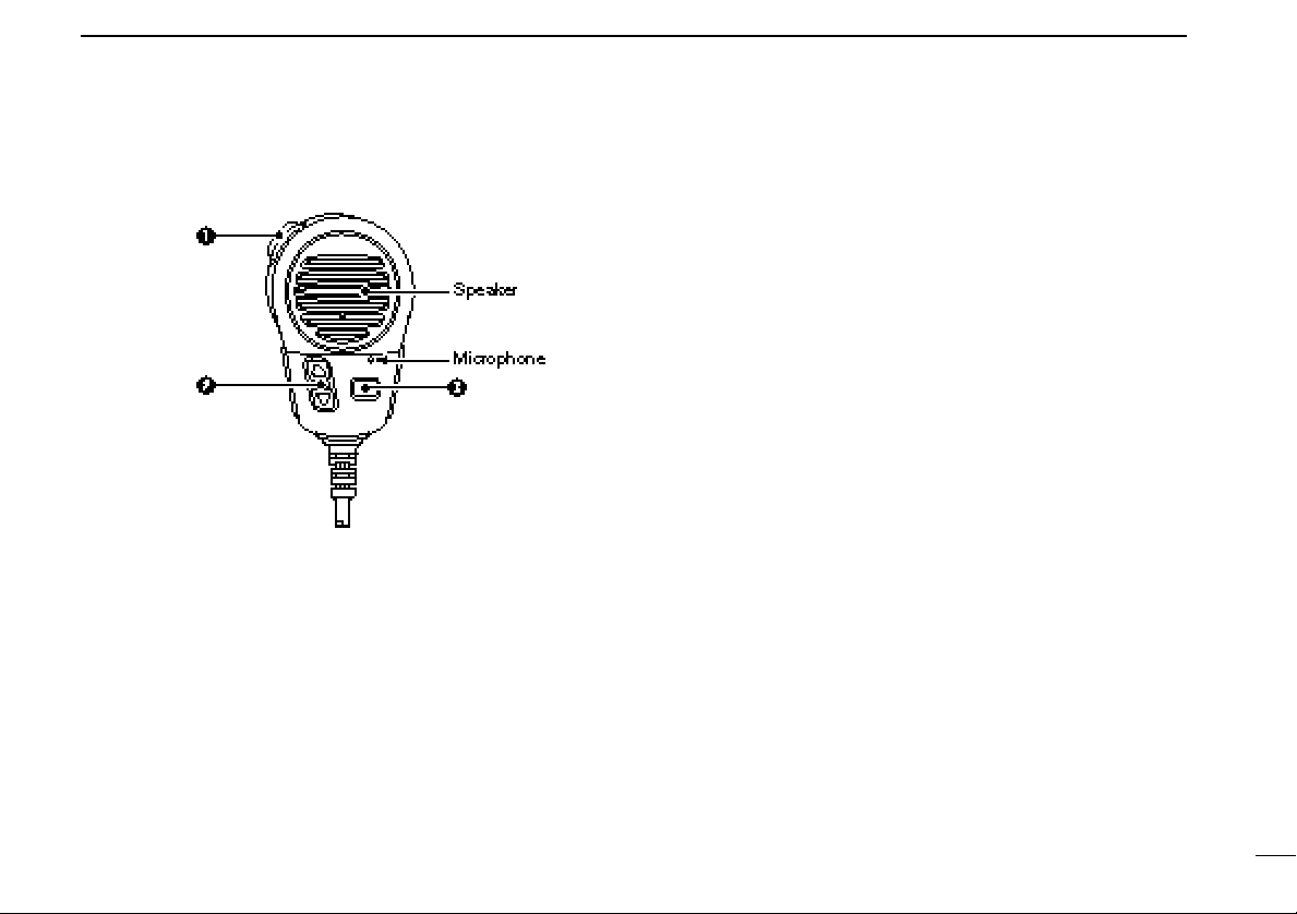
■ Microphone
q PTT SWITCH [PTT]
Push and hold to transmit; release to receive. (p. 8)
w CHANNEL UP/DOWN SWITCHES [YY]/[ZZ]
Push either switch to change the operating memory channel, set mode contents, etc. (p. 8)
PANEL DESCRIPTION
2
e TRANSMIT POWER SWITCH [HI/LO]
➥ Same as the [HI/LO] switch on the front panel. (p. 8)
➥ While pushing [HI/LO] on the supplied microphone, turn
power ON to toggle the lock function ON and OFF. (p.
5
Page 10
3
BASIC OPERATION
■ Channel selection
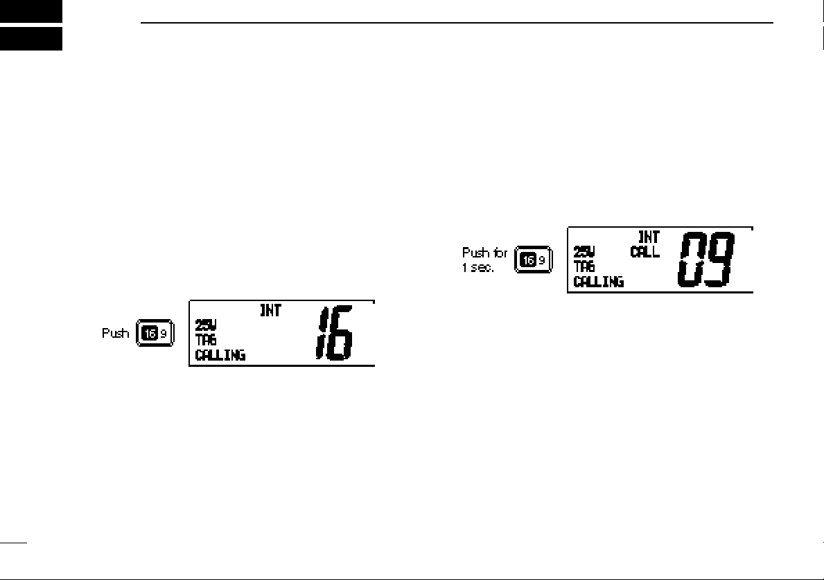
Channel 16
Channel 16 is the distress and safety channel. It is used for
establishing initial contact with another station and for emergency communications. Channel 16 is monitored during both
dualwatch and tri-watch. While standing by, you must monitor
channel 16.
➥ Push [16•9] momentarily to select channel 16.
➥ Push [CH/WX] to return to the condition before selecting
channel 16, or rotate [CHANNEL] to select operating channel.
➥ Push [16•9] for 1 sec. to select the call channel of the se-
lected channel group.
•“CALL” and call channel number appear.
• Each channel group may have an independent call channel after
changing a call channel.
➥ Push [CH/WX] to return to the condition before selecting
call channel
channel.
, or rotate [CHANNEL] to select operating
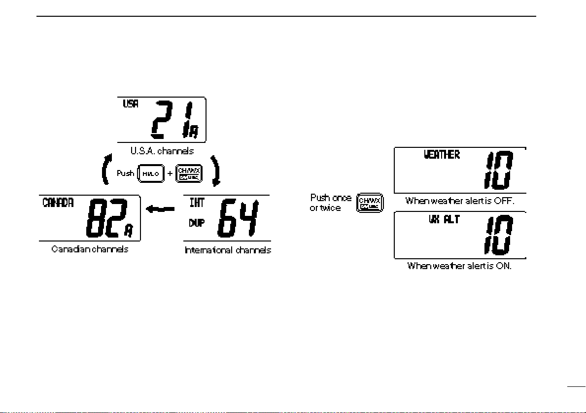
U.S.A., Canadian and international
channels
There are 57 U.S.A., 61 Canadian and 57 international channels. These channel groups may be specified for the operat-
Channel 9 (Call channel)
Each regular channel group has a separate leisure-use call
channel. The call channel is monitored during tri-watch. The
call channels can be programmed (p. 9) and are used to store
your most often used channels in each channel group for
quick recall.
6
ing area.
q Push [CH/WX] to select a regular channel.
• If a weather channel appears, push [CH/WX] again.
w Push [CH/WX•U/I/C] while pushing [HI/LO] to change the
channel group, if necessary.
•U.S.A., International (INT) and Canadian channels can be se-
lected in sequence.
e Rotate the channel selector to select a channel.
Page 11
BASIC OPERATION
3
• “DUP” appears for duplex channels.
• “A” appears for simplex channels.
Weather channels
There are 10 weather channels. Used for monitoring weather
channels from the NOAA (National Oceanographic and Atmospheric Administration) broadcasts.
The transceiver can detect a weather alert tone on the selected weather channel while receiving the channel, during
standby on a regular channel or while scanning. See
“Weather alert” on p. 31.
q Push [CH/WX] once or twice to select a weather channel.
•“WEATHER” appears when a weather channel is selected. “WX
ALT” appears when the weather alert function is in use. (p. 31)
w Rotate the channel selector to select a channel.
• Channels are memorized separately for each channel group.
■ Microphone lock function
The microphone lock function electrically locks the [Y]/[Z]
and [HI/LO] switches on the supplied microphone. This prevents accidental channel changes and accidental function access.
7
Page 12
BASIC OPERATION
3
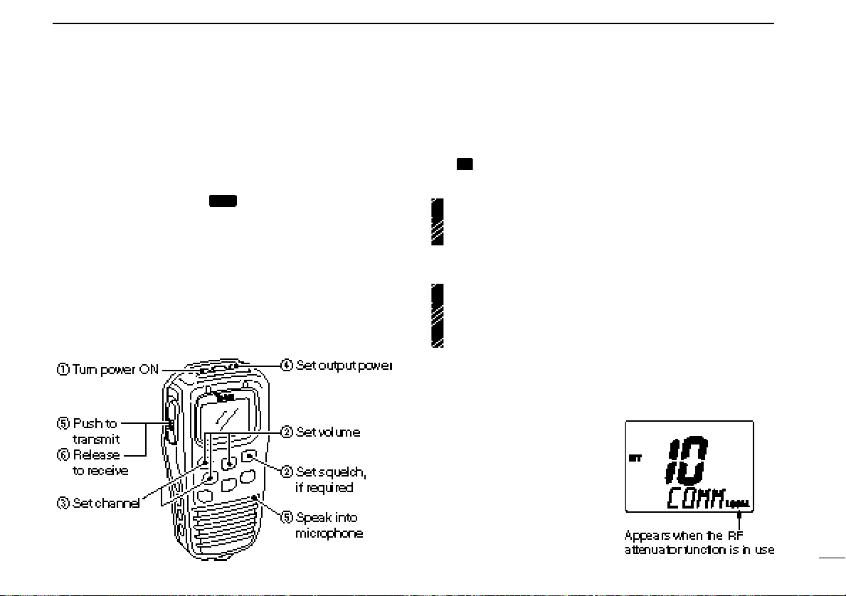
■ Receiving and transmitting
CAUTION: Transmitting without an antenna may dam-
age the transceiver.
q Push [POWER] to turn power ON.
w Set the audio and squelch levels.
➥ Rotate [SQL] fully counterclockwise in advance.
➥ Rotate [VOL] to adjust the audio output level.
➥ Rotate [SQL] clockwise until the noise disappears.
e To change the channel group, push [CH/WX•DW•U/I/C]
while pushing [HI/LO]. (p. 6)
r Rotate the channel selector or push [Y]/[Z] on the micro-
phone to select the desired channel.
•When receiving a signal, “BUSY” appears and audio is emitted
from the speaker.
•Further adjustment of [VOL] may be necessary at this point.
•Use the optional voice scrambler function for privacy. (p. 10)
t Push [LO/DX] to turn the receive attenuator ON or OFF if
necessary.
•“LOCAL” appears when the receive attenuator is in use.
y Push [HI/LO] to select the output power if necessary.
•“25W” or “1W” appears when high or low power is selected, respectively.
•Choose low power to conserve power, choose high power for
longer distance communications.
• Some channels are for low power only.
u Push and hold [PTT] to transmit, then speak into the mi-
crophone.
• “TX” appears.
• Channel 70 cannot be used for transmission (for GMDSS use).
Simplex channels, 3, 21, 23, 61, 64, 81, 82 and 83 CAN-
NOT be lawfully used by the general public in U.S.A. waters.
i Release [PTT] to receive.
IMPORTANT: To maximize the readability of your transmitted signal, pause a few sec. after pushing [PTT], hold
the microphone 4 to 6 inches (10 to 15 cm) from your
mouth and speak at a normal voice level.
8
Page 13
BASIC OPERATION
3
■ Call channel programming
The call channel is used to select channel 9, however, you
can program your most often-used channels in each channel
group for quick recall.
q While pushing [HI/LO], push [CH/WX•DW•U/I/C] one or
more times to select the desired channel group (U.S.A., International, Canada) to be programmed.
w Push [16•9] for 1 sec. to select the call channel of the se-
lected channel group.
•“CALL” and call channel number appear.
•The order of indication precedence is “LOCAL,” “SP OFF” and
“CALL.”
e Push [16•9] again for 3 sec.
(until long beep changes to
2 short beeps) to enter call
channel programming condition.
•Channel number starts flashing.
r Rotate the channel selector
to select the desired channel.
t Push [16•9] to program the displayed channel as the call
channel.
• Push [CH/WX] to cancel.
•The channel number stops flashing.
■ Channel names
Memory channels can be tagged with alphanumeric names
of up to 10 characters each.
Capital letters, small letters, numerals, some symbols (! " # $
% & ' ( ) ✱ + ,– .⁄ ) and spaces can be used.
q Select the desired memory channel.
• Cancel dual watch, tri-watch or scan in advance.
w While pushing [HI/LO], push [16•9] to edit memory chan-
nel name.
• A cursor appears and blinks.
e Select the desired character by rotating the channel selec-
tor or by pushing [Y]/[Z] on the microphone.
• Push [SCAN] or [CH/WX] for cursor movement.
r Push [16•9] to input and set the name.
• Push [HI/LO] to cancel.
•The cursor disappears.
t Repeat steps q to r to program other memory channel
names, if desired.
9
Page 14
BASIC OPERATION
3
■ Optional voice scrambler operation
Activating the scrambler
The optional voice scrambler provides private communications. In order to receive or send scrambled transmissions
you must first activate the scrambler function. To activate the
function, an optional UT-98 or UT-112 is necessary. See p. 33
for selecting the unit. Ask your dealer for details.
The scrambler function automatically turns OFF when
channel 16 or 70 is selected.
q Select an operating channel other than channel 16 and 70.
w While pushing [HI/LO], push [LO/DX•IC/SCR] to toggle an
optional scrambler function ON or OFF.
• “SC” appears.
e To turn the scrambler function OFF, repeat step w.
• “SC” disappears.
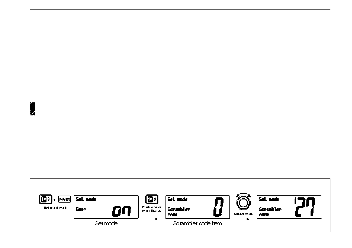
[Example]: Programming scrambler code 127.
Programming scrambler codes
There are 128 or 32 codes (0 to 127 or 1 to 32) available for
programming when the optional UT-98 or UT-112 is installed.
In order to understand one another, all transceivers in your
group must have the same scramble code. This function may
not be available depending on dealer setting.
q Turn power OFF.
w While pushing [16•9], turn power ON to enter set mode.
e After the display appears, release [16•9].
r Push [16•9] one or more times to select the scrambler
code item.
• “Scrambler code” appears.
t Rotate the channel selector to select the desired scram-
bler code.
y Turn power OFF, then ON again to exit set mode.
10
Page 15

DUAL WATCH/TRI-WATCH
4
■ Description
Dualwatch monitors channel 16 while you are receiving another channel; tri-watch monitors channel 16 and the call
channel while receiving another channel.
DUALWATCH/TRI-WATCH SIMULATION
•If a signal is received on channel 16, dualwatch/tri-watch pauses
on channel 16 until the signal disappears.
•If a signal is received on the call channel during tri-watch, triwatch becomes dualwatch until the signal disappears.
•To transmit on the selected channel during dualwatch/tri-watch,
push and hold [PTT].
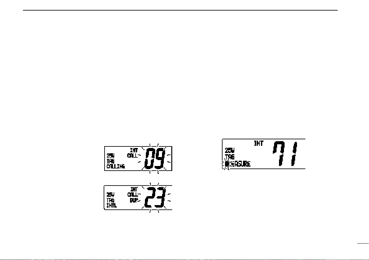
■ Operation
q Select the desired operating channel.
w Select dualwatch or tri-watch in set mode. (p. 31)
e Push [CH/WX•DW•U/I/C] for 1 sec. to start dualwatch or
tri-watch.
• “DUAL” appears during dualwatch; “TRI” appears during tri-
watch.
• Beep tone sounds when a signal is received on channel 16.
r To cancel dualwatch/tri-watch, push [CH/WX•DW•U/I/C]
[Example]: Operating tri-watch on INT channel 25.
11
Page 16

5
SCAN OPERATIONS
■ Scan types
Scanning is an efficient way to locate signals quickly over a
wide frequency range. The transceiver has priority scan and
normal scan.
When the weather alert function is in use, the selected
weather channel is checked while scanning. (p. 31)
PRIORITY SCAN
Priority scan searches through all tag channels in sequence while monitoring channel 16. When a signal is detected on channel 16, scan pauses until the signal disappears; when a signal is detected on a channel other than
channel 16, scan becomes dualwatch until the signal disappears.
Set the tag channels (scanned channel) before scanning.
Clear the tag channels which inconveniently stop scanning,
such as digital communication use.
Choose priority or normal scan in set mode. (p. 31)
NORMAL SCAN
Normal scan, like priority scan, searches through all tag
channels in sequence. However, unlike priority scan, channel 16 is not checked unless channel 16 is set as a tag
channel.
12
Page 17
SCAN OPERATION
5
■ Setting tag channels
For more efficient scanning, add desired channels as tag
channels or clear tag channels for unwanted channels. Channels set as non-tag channels will be skipped during scanning.
Tag channels can be assigned to each channel group
(U.S.A., International, Canada) independently.
q While pushing [HI/LO], push [CH/WX•DW•U/I/C] one or
more times to select the desired channel group, if desired.
w Select the desired channel to set as a tag channel.
e Push [SCAN•TAG] for 1 sec. to set the displayed channel
as a tag channel.
• “TAG” appears in the function display.
r To cancel the tag channel setting, repeat e.
• “TAG” disappears.
• Clearing all tag channels in the selected channel group
➥ While pushing [HI/LO], push [SCAN•TAG] for 3 sec. to
clear all tag channels in the channel group.
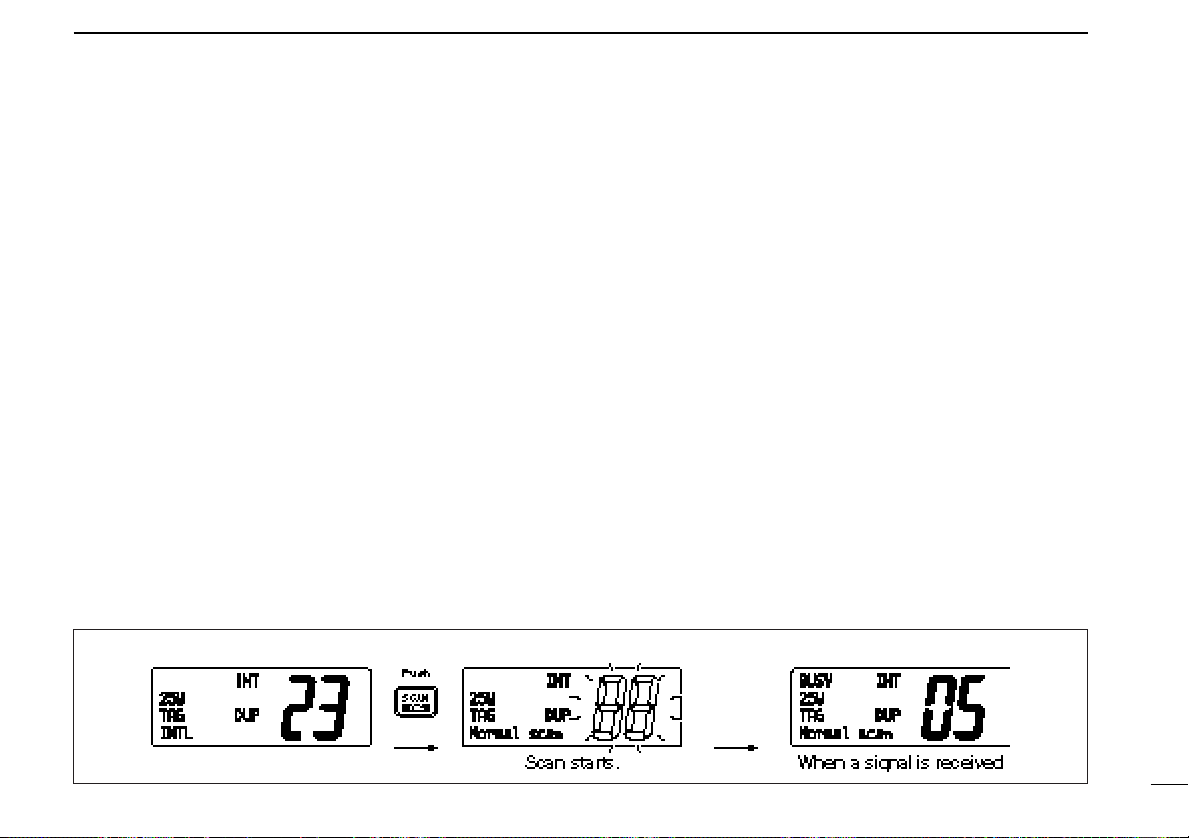
[Example]: Starting a normal scan.
■ Starting a scan
Set scan type (priority or normal scan) and scan resume timer
in advance using set mode. (p. 31)
q Set tag channels as described at left.
w Make sure the squelch is closed to start a scan.
e While pushing [HI/LO], push [CH/WX•DW•U/I/C] one or
more times to select the desired channel group, if desired.
r Push [SCAN] to start priority or normal scan.
• “Pri scan 16” or “Normal scan” appears in the function display.
•When a signal is detected, scan pauses until the signal disappears or resumes after pausing 5 sec. according to set mode setting. (Channel 16 is still monitored during priority scan.)
•Rotate the channel selector to check the scanning tag channels,
to change the scanning direction or resume the scan manually.
•“16” flashes and a beep tone sounds when a signal is received
on channel 16 during priority scan.
•Push [SCAN•TAG] for 1 sec. to set the paused channel as a tag
channel.
t To stop the scan, push [SCAN].
13
Page 18
6
DSC OPERATION
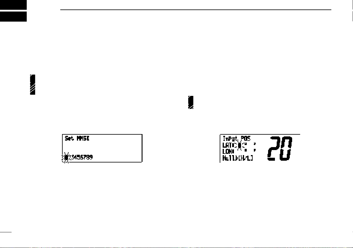
■ MMSI code programming
The 9-digit MMSI (DSC self ID) code can be programmed at
power ON.
This function is not available when the MMSI code has
been programmed by the dealer. This code programming
can be performed only 2 times.
q Turn power OFF.
w While pushing [DSC/ENT], turn power ON to enter MMSI
code programming condition.
e After the display appears, release [DSC/ENT].
r Select the desired number by rotating the channel selector.
t Push [CH/WX] to advance the cursor.
• Push [SCAN] to move the cursor backward.
y Repeat steps r and t to input 9 digit code.
u Push [DSC/ENT] to input and set the code.
• The previously selected channel appears.
■
Position and time programming
A distress call should include the ship’s position and time. If
no GPS is connected, your position and UTC (Universal Time
Coordinated) time should be input. They are included automatically when a GPS receiver (NMEA0183 ver. 2.0) is connected.
This function is not available when an optional GPS receiver (NMEA0183 ver. 2.0) is connected.
q Push [DSC/ENT] twice to enter the position programming
condition.
w Rotate the channel selector to select the digit of your posi-
tion.
e Push [CH/WX] to advance the cursor.
• Push [SCAN] to move the cursor backward.
• Push [HI/LO] to clear the position data.
14
Page 19

DSC OPERATION
6
r Push [DSC/ENT] to set the position and advance to time
setting condition.
• Push [LO/DX] to abandon the setting and exit the condition.
t Rotate the channel selector to select the digit of current
UTC time.
y Push [CH/WX] to advance the cursor.
• Push [SCAN] to move the cursor backward.
• Push [HI/LO] to clear the time.
u Push [DSC/ENT] to set the time.
•Push [LO/DX] to abandon the setting and exit the condition.
■ Position indication
When an optional GPS receiver (NMEA0183 ver. 2.0) is connected, the transceiver can display the current position and
time. When no GPS receiver is connected, the transceiver
displays the manually entered position and time.
A GPS receiver appropriate for the IC-M502 is not supplied
from Icom. An NMEA0183 ver. 2.0 is required for position indication. Ask your dealer about the GPS receiver.
➥ Push [DSC/ENT•POS] for 1 sec. to display the current po-
sition and time.
•“MNL” (manual) appears instead of the “GPS” indication when
the position data is entered manually.
15
Page 20
DSC OPERATION
6
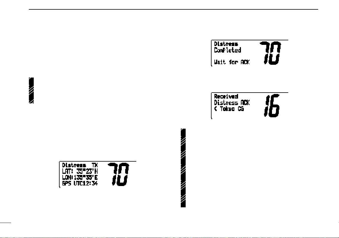
■ Distress call
A distress call should be transmitted if, in the opinion of the
Master, the ship or a person is in distress and requires immediate assistance.
16
NEVER USE THE DISTRESS CALL WHEN
YOUR SHIP IS NOT IN AN EMERGENCY. A
DISTRESS CALL CAN BE USED ONLY WHEN
IMMEDIATE HELP IS NEEDED.
q Confirm any distress call is not being received.
w While lifting up the switch cover, push the [DISTRESS]
switch for 5 sec. to transmit the distress call.
• An emergency channel (Ch 70) is automatically selected and the
distress call is transmitted.
• If no GPS is connected, input your position and UTC time, if possible.
e After transmitting the call, the transceiver waits for an ac-
knowledgment call on Ch70.
•The distress call is automatically transmitted every 3.5 to 4.5
minutes.
r When receiving the acknowledgment, reply to the con-
nected station via the microphone.
➥ Distress alert contains (default);
• Kinds of distress : Undesignated distress
• Position data : GPS or manual input position data held for
23.5 hrs. or until the power is turned OFF.
➥ The distress call is repeated every 3.5–4.5 min., until re-
ceiving an ‘acknowledgement.’
➥ Push [DISTRESS] to transmit a renewed distress call, if
desired.
➥ Push [16•9] to cancel the ‘Call repeat’ mode.
➥ ‘??’ may blink instead of position and time indications,
when the GPS data is invalid, or 4 hours after the time
data is input manually.
Page 21
DSC OPERATION
6
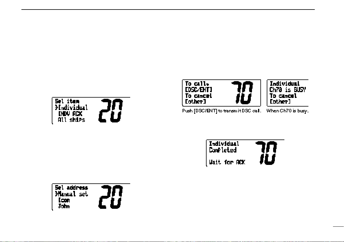
■ Transmitting DSC calls
Transmitting individual call
The individual call function allows you to transmit a DSC signal to a specific party only.
q Select a desired channel other than channel 70.
w Push [DSC/ENT] to select the DSC menu.
e Rotate the channel selector to select “individual” and push
[DSC/ENT].
r Rotate the channel selector to select the desired pre-pro-
grammed individual address; or push [DSC/ENT] while
“Manual set” is displayed, to set the ID code for the individual you wish to call.
• The ID code for the individual call can be set in advance. (p. 22)
t Push [DSC/ENT] to transmit the individual call.
•Channel 70 is selected and the individual call is transmitted to
the selected station.
•If channel 70 is busy, the transceiver standbys until the channel
becomes clear.
• Routine category only is available.
y Standby on channel 70 until an acknowledgement is re-
ceived.
u When the acknowledgement is received, the display
changes to the previously selected user channel with
beeps.
i Push and hold [PTT] to communicate your message to the
responding party.
17
Page 22

DSC OPERATION
6
Transmitting individual acknowledgement
Transmit an acknowledgement (‘able to comply’ or ‘unable to
comply’) when an individual call for you is received.
q Select a desired channel other than channel 70.
w Push [DSC/ENT] to select the DSC menu.
e Rotate the channel selector to select “INDV ACK” and
push [DSC/ENT].
• “INDV ACK” appears after an individual call is received.
r Rotate the channel selector to select the desired individ-
ual address or ID code, then push [DSC/ENT].
y If you select ‘Unable,’ select the reason by rotating the
channel selector, then push [DSC/ENT].
•‘No reason given,’ ‘Congestion,’ ‘Busy,’ ‘Queue indication,’
‘Barred (Station barred),’ ‘No operator,’ ‘No Equip (Equipment
disable),’ ‘No channel (Unable channel)’ and ‘No mode (Unable
mode)’ are available.
u Push [DSC/ENT] to transmit the acknowledgement to the
selected station.
18
t Rotate the channel selector to select an acknowledgement
(‘Able’ or ‘Unable’), then push [DSC/ENT].
i The individual acknowledgement has been transmitted.
Page 23

DSC OPERATION
6
Transmitting all ships call
Large ships use channel 70 as their “listening channel.” When
you want to announce a message to these ships, use the “all
ships call” function.
q Select a desired channel other than channel 70.
w Push [DSC/ENT] to select the DSC menu.
e Rotate the channel selector to select “All ships” and push
[DSC/ENT].
r Push [DSC/ENT] to transmit the all ships call.
•Channel 70 is selected and the all ships call is transmitted.
• Routine category only is available.
t The all ships call has been transmitted.
y Push [PTT] or rotate the channel selector to exit the condi-
tion.
19
Page 24

DSC OPERATION
6
Transmitting position request call
Transmit a position request call when you want to know your
friend’s current position, etc.
q Select a desired channel other than channel 70.
w Push [DSC/ENT] to select the DSC menu.
e Rotate the channel selector to select “POS request” and
push [DSC/ENT].
y Push [PTT] or rotate the channel selector to exit the condi-
tion.
Transmitting position reply call
Transmit a position reply call when a position request call is
received.
20
r Push [DSC/ENT] to transmit the position request call.
•Channel 70 is selected and the position request call is transmitted.
t The position request call has been transmitted.
q When a position request call is received, the function dis-
play shows as follows.
w Push [DSC/ENT] to reply the position request call; push
[HI/LO] to ignore the position request call.
Page 25

DSC OPERATION
6
■
Setting the distress information
The nature of the distress call should be included in the distress call.
q Push [DSC/ENT] to select the DSC menu.
w Rotate the channel selector to select “DTRS set” and push
[DSC/ENT].
e Rotate the channel selector to select the nature of the dis-
tress, then push [DSC/ENT].
•‘Undesign (Undesigned),’ ‘Explosion,’ ‘Flooding,’ ‘Collision,’
‘Grounding,’ ‘Capsizing,’ ‘Sinking,’ ‘Adrift (Disable adrift),’ ‘Abandoning (Abandoning ship),’ ‘Piracy (Piracy attack),’ ‘MOB (Man
overboard)’ and ‘EPIRB (EPIRB emission)’ are available.
r The position information appears. Set the current position,
then push [DSC/ENT].
• Rotate the channel selector to select the character.
• Push [CH/WX] to advance the cursor.
• Push [SCAN] to move the cursor backward.
• Push [HI/LO] to clear the position data.
t The time information appears. Set the current time, then
push [DSC/ENT].
• Rotate the channel selector to select the numeral.
• Push [CH/WX] to advance the cursor.
• Push [SCAN] to move the cursor backward.
• Push [HI/LO] to clear the time data.
y Push [DISTRESS] for 5 sec. to transmit the distress call.
• Push [DSC/ENT] to exit the condition.
• The selected nature of the distress is stored for 10 minutes.
21
Page 26
DSC OPERATION
6
■ DSC individual ID
A total of 40 DSC address ID’s can be programmed and
named with up to 10 characters.
22
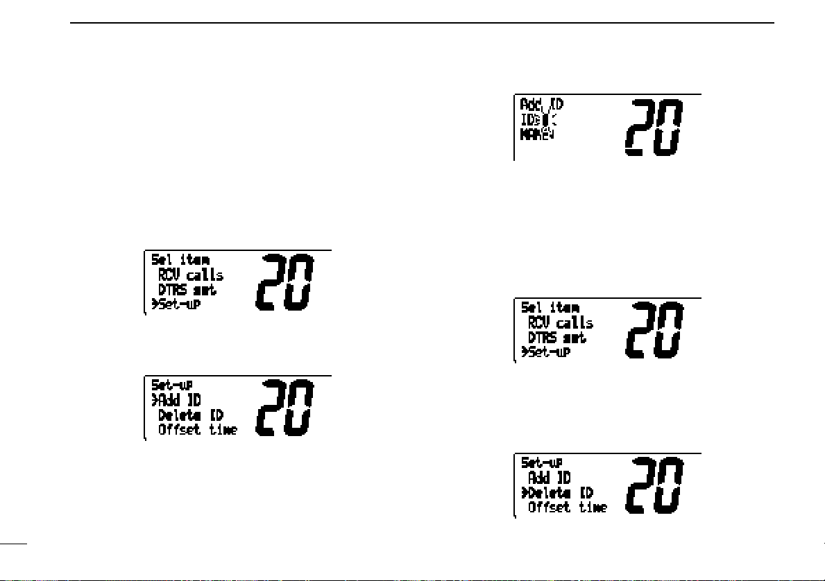
Programming address ID
q Push [DSC/ENT] to select the DSC menu.
w Rotate the channel selector to select “Set-up” and push
[DSC/ENT].
e Rotate the channel selector to select ‘Add ID,’ then push
[DSC/ENT].
r Set the distress ID and ID name, then push [DSC/ENT].
• Rotate the channel selector to select the character.
• Push [CH/WX] to advance the cursor.
• Push [SCAN] to move the cursor backward.
•Push [HI/LO] to cancel and exit the condition.
t Push [DSC/ENT] to program and to exit the condition.
Deleting address ID
q Push [DSC/ENT] to select the DSC menu.
w Rotate the channel selector to select “Set-up” and push
[DSC/ENT].
e Rotate the channel selector to select ‘Delete ID,’ then push
[DSC/ENT].
•When no address ID is programmed, the transceiver exits the
condition automatically.
Page 27
DSC OPERATION
6
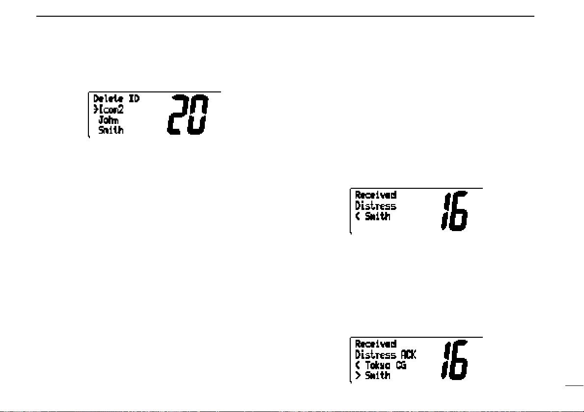
r Select the desired ID name with the channel selector, then
push [DSC/ENT].
t Push [DSC/ENT] to delete the address ID; push other
switch to exit the condition.
■ Receiving DSC calls
Receiving a distress call
While monitoring channel 70 and a distress call is received:
➥ Emergency alarm sounds for 2 minutes.
• Push any switch to stop the alarm.
➥ “Received Distress” appears in the display; then, channel
16 is automatically selected.
➥ Continue monitoring channel 16 as a coast station may re-
quire assistance.
Receiving a distress acknowledgement
While monitoring channel 70 and a distress acknowledgement to other ship is received:
➥ Emergency alarm sounds for 2 minutes.
• Push any switch to stop the alarm.
➥ “Received Distress ACK” appears in the display; then,
channel 16 is automatically selected.
23
Page 28

DSC OPERATION
6
Receiving a distress relay acknowledgement
While monitoring channel 70 and a distress relay acknowledgement is received:
➥ Emergency alarm sounds for 2 minutes.
• Push any switch to stop the alarm.
➥ “Received DTRS RLY ACK” appears in the display; then,
channel 16 is automatically selected.
Receiving a distress relay call
While monitoring channel 70 and a distress relay call is received:
➥ Emergency alarm sounds for 2 minutes.
• Push any switch to stop the alarm.
➥ “Received Distress RLY” appears in the display; then,
channel 16 is automatically selected.
➥ Monitor channel 16 until the emergency communication
has been completed.
Receiving an all ships call
While monitoring channel 70 and an all ships call is received:
➥ Emergency alarm sounds when the category is “Distress”
or “Urgency;” 3 beeps sound for other categories.
➥ “All ships Distress,” “All ships Safety” or “All ships Urgency”
appears in the display; then, the channel specified by the
calling station is automatically selected for voice communication.
➥ Monitor the selected channel for an announcement from
the calling vessel.
Receiving an individual call
While monitoring channel 70 and an individual call is received:
➥ Emergency alarm or beeps sound depending on the re-
ceived category.
➥ “Individual Distress,” “Individual Safety,” “Individual Ur-
gency” or “Individual Routine” appears in the display.
➥ The channel specified by the calling station is automatically
selected for checking the channel condition.
24
Page 29
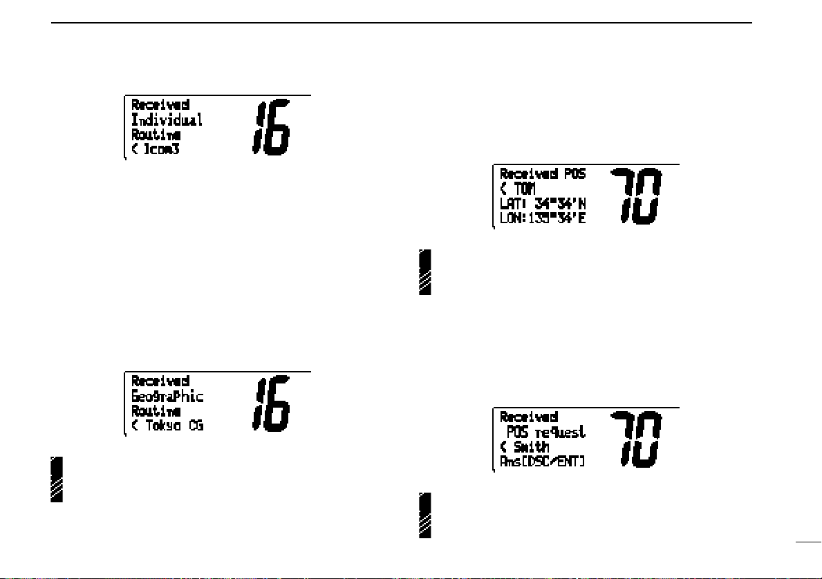
Receiving a geographical area call
While monitoring channel 70 and a geographical area call (for
the area you are in) is received:
➥ Emergency alarm or beeps sound depending on the re-
ceived category.
➥ “Geographic Distress,” “Geographic Safety,” “Geographic
Urgency” or “Geographic Routine” appears in the display;
then, the channel specified by the calling station is automatically selected for voice communications.
➥ Monitor the selected channel for an announcement from
the calling ship.
DSC OPERATION
6
Receiving a position reply call
While monitoring channel 70 and a position reply call (for the
area you are in) is received:
➥ “Received POS” appears in the display.
When no GPS receiver is connected or if there is a problem with the connected receiver, all geographical area calls
are received, regardless of your position.
Receiving a position request call
While monitoring channel 70 and a position request call (for
the area you are in) is received:
➥ “POS request” appears in the display.
➥ Push [DSC/ENT] to reply to the call.
When no GPS receiver is connected or if there is a problem with the connected receiver, all geographical area calls
are received, regardless of your position.
When no GPS receiver is connected or if there is a problem with the connected receiver, all geographical area calls
are received, regardless of your position.
25
Page 30
DSC OPERATION
6
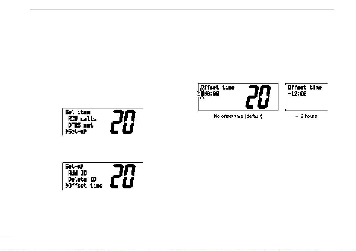
■ DSC set mode
Offset time
This item sets the offset time from the UTC (Universal Time
Coordinated) time.
q Push [DSC/ENT] to select the DSC menu.
w Rotate the channel selector to select “Set-up” and push
[DSC/ENT].
e Rotate the channel selector to select ‘Offset time,’ then
push [DSC/ENT].
r Set the offset time from the UTC (Universal Time Coordi-
nated) time, then push [DSC/ENT].
• Rotate the channel selector to select the number, ‘+’ or ‘–.’
• Push [CH/WX] to advance the cursor.
• Push [SCAN] to move the cursor backward.
• Push [HI/LO] to cancel and exit the condition.
t Push [DSC/ENT] to program and to exit the condition.
26
Page 31
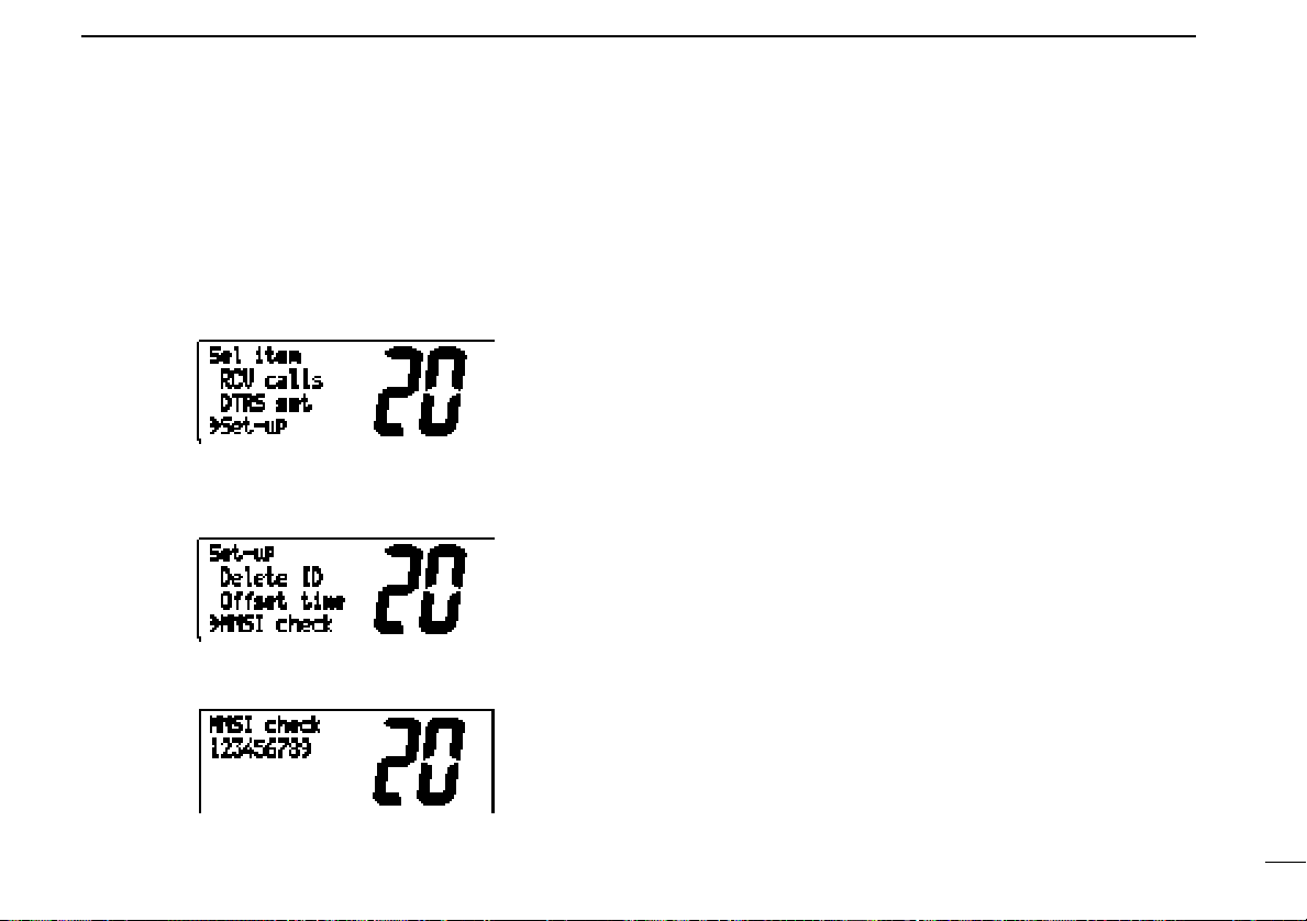
MMSI code check
The 9-digit MMSI (DSC self ID) code can be checked in set
mode.
q Push [DSC/ENT] to select the DSC menu.
w Rotate the channel selector to select “Set-up” and push
[DSC/ENT].
e Rotate the channel selector to select ‘MMSI check,’ then
push [DSC/ENT].
r Check the 9-digit MMSI (DSC self ID) code.
DSC OPERATION
6
t Push [DSC/ENT] to exit the condition.
27
Page 32

DSC OPERATION
6
■ Receive messages
The transceiver automatically stores up to 20 distress messages and 20 other messages. The messages can be used
as an assistance to the logbook.
q Push [DSC/ENT] to select the DSC menu.
w Rotate the channel selector to select “RCV calls” and push
[DSC/ENT].
• “RCV calls” does not appear until a distress call is received.
e Rotate the channel selector to select distress messages or
other messages, then push [DSC/ENT].
r Rotate the channel selector to select the desired message,
then push [DSC/ENT].
t Rotate the channel selector to scroll the message.
• The stored message has several information and depends on the
distress call types.
y Push [DSC/ENT] to exit the condition or push [HI/LO] to
clear the displayed messages.
28
Page 33

INTERCOM OPERATION
7
■ Intercom operation
The optional intercom function allows you to talk to the deck
from the cabin. The optional HM-127
CROPHONE is required for intercom operation.
Connect an optional HM-127 as described on p. 35.
• Transmitting is impossible during intercom operation.
• The received signal is muted during intercom operation.
q Push [LO/DX•IC•SCR] for 1 sec. to enter intercom mode.
• The HM-127 power is automatically turned ON, even if the power
is OFF.
w Push and hold [LO/DX•IC•SCR] again to call up.
• The transceiver and microphone emit call beeps.
e Push and hold the PTT switch and speak at a normal voice
level into the microphone.
•“TALK” or “LSTN” appears on the caller or listener function display, respectively.
•To adjust the IC-M502’s speaker output level, rotate [VOL].
REMOTE-CONTROL MI-
•To adjust the HM-127’s speaker output level, push [Y]/[Z] after
pushing [VOL].
r After releasing the PTT switch you can hear the response
through the speaker.
t To return to normal operation, push [LO/DX•IC•SCR] mo-
mentarily.
•Other switches also turn the function OFF, however, the corresponding function is then activated e.g. pushing [16•9] selects
channel 16.
•While in the intercom mode, the transceiver functions
(transmit and receive) are interrupted. If the transceiver is
in transmit condition, the intercom function is not available.
•When a DSC call is received, “DSC received” appears
and the last received DSC message is displayed after the
intercom use is finished.
•When a WX alert is received, “WX ALT” flashes and a
beep sounds. The WX alert sounds after the intercom use
is finished.
29
Page 34
8
SET MODE
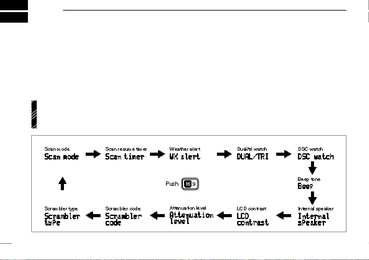
■ Set mode programming
Set mode is used to change the conditions of the transceiver’s functions: scan mode (normal or priority), scan resume timer, weather alert, dualwatch/tri-watch selection, DSC
watch, transceiver’s beep tone, internal speaker (transceiver
or HM-127), LCD contrast (transceiver or HM-127), RF attenuation level, scrambler code and scrambler type.
•Available functions may differ depending on dealer setting.
•The optional HM-127 has it’s own settings for the beep
tone and LCD contrast.
• SET MODE CONSTRUCTION
q Turn power OFF.
w While pushing [16•9], turn power ON to enter set mode.
e After the display appears, release [16•9].
r Push [16•9] to select the desired item, if necessary.
t Rotate the channel selector to select the desired condition
of the item. Use [Y]/[Z] when using an optional HM-127.
y Turn power OFF, then ON again to exit set mode.
30
Page 35
SET MODE
8
■ Set mode items
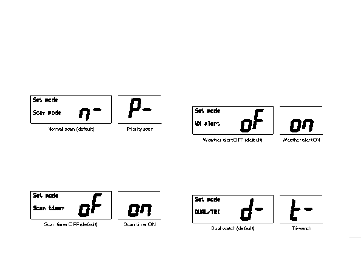
Scan mode
The transceiver has 2 scan modes: normal scan and priority
scan. Normal scan searches all tag channels in the selected
channel group. Priority scan searches all tag channels in sequence while monitoring channel 16.
Scan resume timer
The scan resume timer can be selected as a pause (OFF) or
timer scan (ON). When OFF is selected, the scan pauses
until the signal disappears. When ON is selected, the scan
pauses 5 sec. and resumes even if a signal is being received
on channels except for channel 16.
Weather alert
An NOAA broadcast station transmits a weather alert tone before important weather information. When the weather alert
function is turned ON, the transceiver detects the alert, then
flashes the “WX ALT” indicator until the transceiver is operated. The previously selected (used) weather channel is
checked any time during standby or while scanning.
•“WX ALT” appears instead of “WEATHER” indication when the function is set ON.
Dual/tri watch
This item sets the [CH/WX•DW] switch function as dual watch
or tri-watch.
See the section ‘Dual watch/Tri-watch’ for details.
31
Page 36

SET MODE
8
DSC watch
DSC watch monitors channel 70 while you are receiving another channel.
If a distress signal is received on channel 70, the transceiver
monitors channel 16 and 70 alternately until the distress signal disappears. If a signal is received on another channel,
DSC watch pauses until the signal disappears.
This function may not be available for some channel
groups depending on dealer setting.
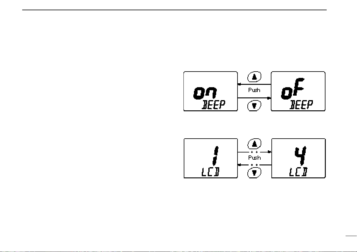
Beep tone
You can select silent operation by turning beep tones OFF or
you can have confirmation beeps sound at the push of a
switch by turning beep tones ON.
Internal speaker
When an optional external speaker is connected and the
transceiver’s internal speaker is not required, the speakers
on the transceiver and microphone can be deactivated.
“SP OFF” appears on the function display when the internal
speaker is turned OFF.
•The order of indication precedence is “LOCAL,” “SP OFF” and
“CALL.”
32
The optional HM-127 has it’s own setting for the beep tone.
Page 37

SET MODE
8
LCD contrast
This item adjusts the contrast of the LCD in 8 steps.
The optional HM-127 has it’s own setting for the LCD contrast.
Attenuation level
This item sets the receive attenuation level for the attenuator
function from 3 levels.
Scrambler code
When an optional scrambler unit is connected, the scrambler
code can be set depending on dealer setting.
When the UT-98 or UT-112 is installed, 128 or 32 codes (0 to
127 or 1 to 32) can be selected, respectively.
Scrambler type
When an optional scrambler unit is connected, the scrambler
type can be selected in set mode depending on dealer setting.
33
Page 38

9
CONNECTIONS AND MAINTENANCE
■ Supplied accessories
The following accessories are supplied: Qty.
q Mounting bracket ............................................................ 1
w Microphone hanger (OPC-562) ...................................... 1
e Mic hanger screws (3 × 16) ............................................ 2
r Mounting screws (5 × 20) ............................................... 2
t Flat washers (M5) ........................................................... 2
y Spring washers (M5) ...................................................... 2
u Mounting bracket knobs ................................................. 2
i DC power cable (OPC-946) ........................................... 1
■ Antenna
A key element in the performance of any communication system is an antenna. Ask your dealer about antennas and the
best places to mount them.
■ Fuse replacement
One fuse is installed in the supplied DC power cable. If a fuse
blows or the transceiver stops functioning, track down the
source of the problem, if possible, and replace the damaged
fuse with a new, rated one.
■ Cleaning
If the transceiver becomes dusty or dirty, wipe it clean with a
soft, dry cloth.
34
AVOID the use of solvents such as benzene or alcohol, as they may damage transceiver surfaces.
Page 39
CONNECTIONS AND MAINTENANCE
9
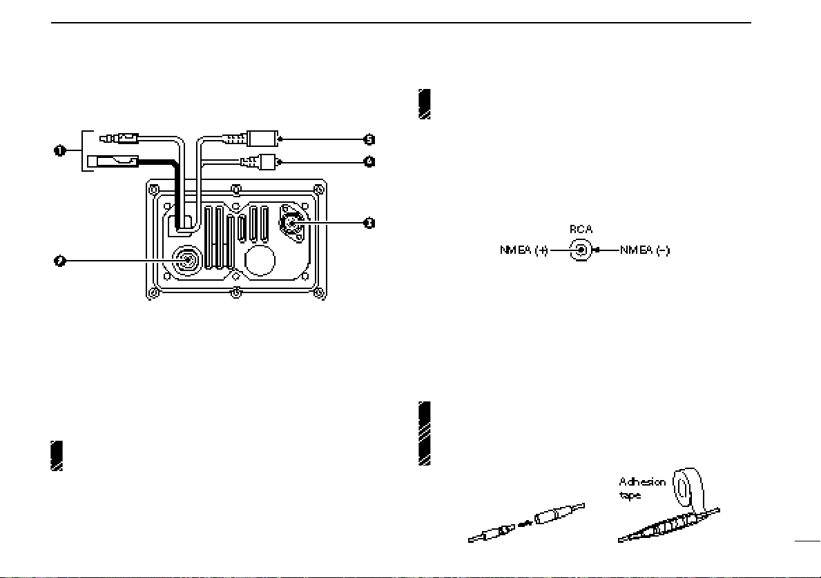
■ Connections
q DC POWER CONNECTOR
Connects the supplied DC power cable from this connector
to an external 12 V DC power source.
w EXTERNAL MICROPHONE JACK
Connects to optional HM-127
PHONE.
CAUTION: NEVER connect other microphone such
as the HM-134, etc. may cause damage the transceiver.
REMOTE-CONTROL MICRO-
CAUTION: Transmitting without an antenna may dam-
age the transceiver.
r GPS RECEIVER JACK
Connects to an optional GPS receiver to input the position
data and time data.
•An NMEA0183 ver. 2.0 is required for position or time indication,
etc. Ask your dealer about the GPS receiver.
t EXTERNAL SPEAKER JACK
Connects to an external speaker. See ‘Options’ on p. 43
for available external speakers.
MICROPHONE HANGER
Rest the supplied microphone on the hanger when not in
use.
CAUTION: After connecting the DC power cable, GPS
receiver jack and external speaker jack, cover the connector and jacks with an adhesion tape as shown below to
prevent water seeping into the transceiver.
e ANTENNA CONNECTOR
Connects a marine VHF antenna with a PL-259 connector
to the transceiver.
35
Page 40
CONNECTIONS AND MAINTENANCE
9
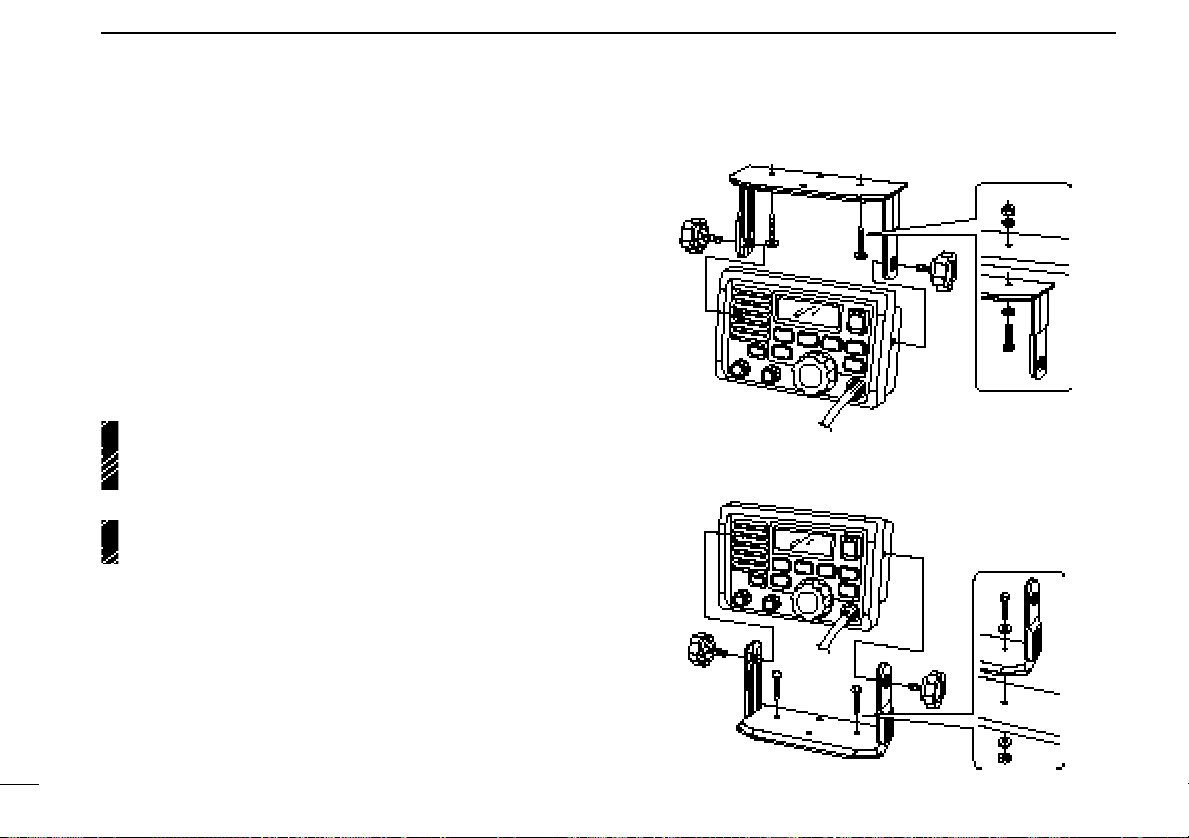
■ Mounting the transceiver
Using the supplied mounting bracket
The universal mounting bracket supplied with your transceiver
allows overhead or dashboard mounting.
•Mount the transceiver securely with the 2 supplied screws
(M5 × 20) to a surface which is more than 10 mm thick and
can support more than 5 kg.
• Mount the transceiver so that the face of the transceiver is at
90° to your line of sight when operating it.
CAUTION: KEEP the transceiver and microphone at
least 1 meter away from your vessel’s magnetic navigation
compass.
NOTE: Check the installation angle; the function display
may not be easy-to-read at some angles.
• OVERHEAD MOUNTING
• MOUNTING ON DASHBOARD
36
Page 41
CONNECTIONS AND MAINTENANCE
9
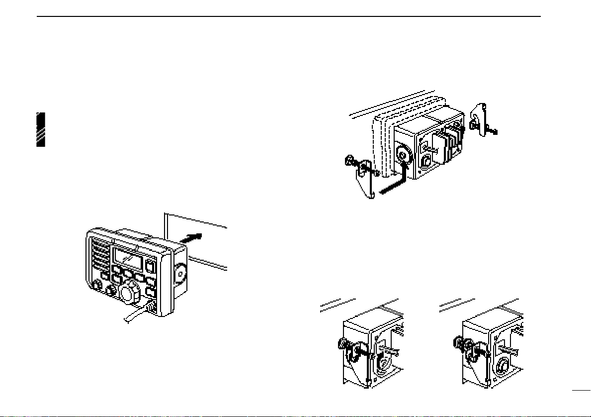
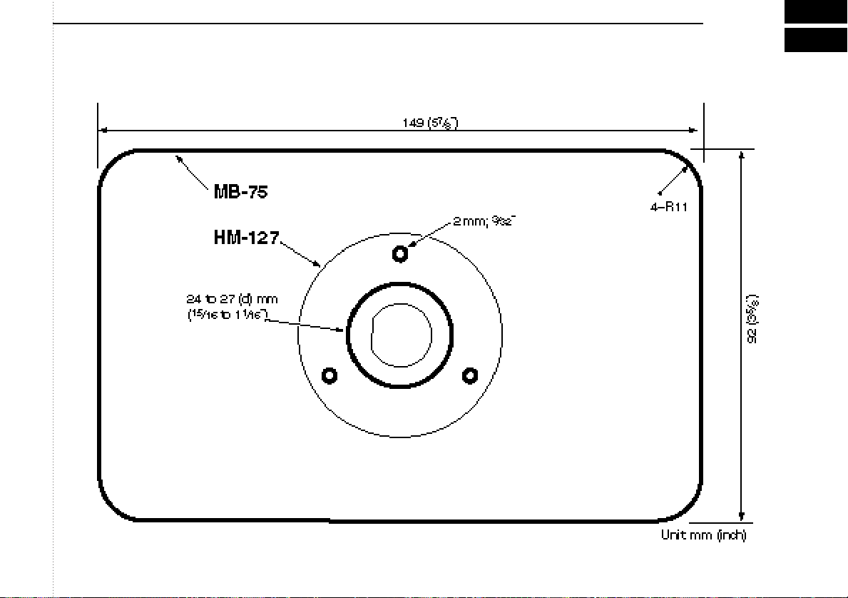
Using the optional mounting bracket
An optional MB-75 FLUSH MOUNT is available for mounting
the transceiver to a flat surface such as an instrument panel.
CAUTION: KEEP the transceiver and microphone at
least 1 meter away from your vessel’s magnetic navigation
compass.
q Using the template on the last page, carefully cut a hole
into the instrument panel (or wherever you plan to mount
the controller).
w Slide the transceiver through the hole as shown below.
e Attach the 2 supplied bolts (M5 × 8 mm) on either side of
the IC-M502.
r Attach the clamps on either side of the IC-M502.
• Make sure that the clamps align parallel to the IC-M502’s body.
t Tighten the end bolts on the clamps (rotate clockwise) so
that the clamps press firmly against the inside of the instrument control panel.
y Tighten the locking nuts (rotate counterclockwise) so that
the IC-M502 is securely mounted in position as below.
u Connect the antenna and control cable, then return the in-
strument control panel to its original place.
37
Page 42

CONNECTIONS AND MAINTENANCE
9
■ Optional unit installation
CAUTION: DISCONNECT the DC power cable from the
transceiver before performing any work on the transceiver.
Otherwise, there is danger of electric shock and/or equipment damage.
Follow the case opening procedure shown here when you
want to install an optional unit, etc.
q Remove the 6 screws as shown below and open the trans-
ceiver.
w Remove the 4 screws from the shielding plate, then lift up
the shielding plate.
e Plug an optional unit to J6 on the MAIN unit as shown
below.
r Return the shielding plate and assemble the units to their
original positions.
38
Page 43
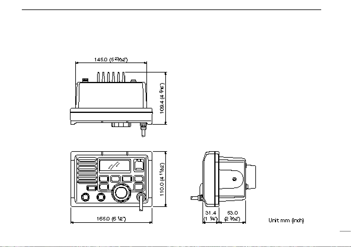
■ Dimensions
CONNECTIONS AND MAINTENANCE
9
39
Page 44

10
TROUBLESHOOTING
40
Page 45

CHANNEL LIST
11
NOTE: Simplex channels, 3, 21, 23, 61, 64, 81, 82 and 83 CANNOT
be lawfully used by the general public in U.S.A. waters.
41
Page 46

12
SPECIFICATIONS AND OPTIONS
■ Specifications
42
General
• Frequency coverage :
Transmit 156.025–157.425 MHz
Receive 156.050–163.275 MHz
• Mode : FM (16K0G3E)
DSC (16K0G2B)
• Channel spacing : 25 kHz
• Current drain (at 13.8 V) : TX high 6.0 A max.
Max. audio 1.2 A max.
• Power supply requirement: 13.8 V DC ±15%
• Frequency stability : ±10 ppm
(–20°C to +60°C; –4°F to
+140°F)
•Dimensions : 165(W) × 110(H)× 109.4(D) mm
(Projection not included) 6
• Weight : 1130 g; 2 lb 8 oz
1
⁄2(W) × 411⁄32(H) × 45⁄16(D) in
Transmitter
• Output power : 25 W and 1 W
• Modulation system : Variable reactance phase
modulation
• Max. frequency deviation : ±5.0 kHz
• Spurious emissions : –70 dB
Receiver
• Receive system :
• Sensitivity (12 dB SINAD) : Less than 0.25 µV (typical)
• Squelch sensitivity : Less than 0.3 µV
•
Intermodulation rejection ratio
•Spurious response : More than 80 dB (typical)
rejection ratio
•
Adjacent channel selectivity
• Audio output power : More than 3.5 W at 10% distor-
All stated specifications are subject to change without
notice or obligation.
Double conversion
superheterodyne
: More than 80 dB (typical)
: More than 80 dB (typical)
tion with a 4 Ω load
Page 47

■ Options
• MB-75 FLUSH MOUNT
For mounting the transceiver to a panel.
• SP-5 EXTERNAL SPEAKER
A large, external speaker for superior audio output.
• SP-10 EXTERNAL SPEAKER
A compact, external speaker. Features easy installation.
• UT-98 VOICE SCRAMBLER UNIT (pgs. 10, 33)
• UT-112 VOICE SCRAMBLER UNIT
Ensures private communications. 128 or 32 codes are available. Not available in some countries.
• HM-127 REMOTE-CONTROL MICROPHONE (p. 44)
External microphone-type controller. Provides optional intercom operation. 6 m (20 feet) microphone cable and mounting base included. Black and white colors are available.
• OPC-999 MICROPHONE EXTENSION CABLE
6 m (20 feet) microphone extension cable for optional
HM-127. Up to 2 OPC-999 can be connected. (18 m; 60 feet
maximum)
SPECIFICATION AND OPTIONS
12
43
Page 48
13
HM-127 REMOTE-CONTROL MICROPHONE
OPTIONAL
44
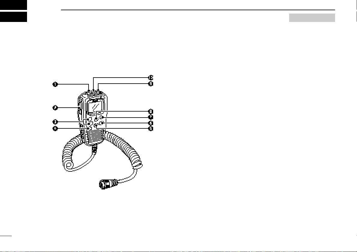
■ Panel description
The optional HM-127 remotely controls the IC-M502 and provides an optional intercom function.
q POWER SWITCH [PWR] (pgs. 8, 51)
Push for 2 sec. to turn the HM-127 power ON or OFF
when the IC-M502 power is turned ON.
w PTT SWITCH [PTT] (pgs. 8, 51)
Push and hold to transmit; release to receive.
e CHANNEL UP/DOWN SWITCHES [YY]/[ZZ]
➥ Push either switch to change the operating channel, set
mode contents, etc. (pgs. 8, 51)
➥ While pushing [H/L], push [Y]/[Z] to adjust the bright-
ness of the LCD and switch backlight. (p. 52)
➥ Push either switch to adjust audio level or noise squelch
level after [VOL] or [SQL] is pushed, respectively. (pgs.
8, 51)
➥ In set mode, changes setting of the selected item. (pgs.
9, 55)
➥ Checks tag channels or changes scanning direction dur-
ing scan. (pgs. 8, 54)
r CHANNEL 16/CALL CHANNEL SWITCH [16•9]
➥ Selects channel 16 when pushed. (pgs. 6, 50)
➥ Selects call channel when pushed for 1 sec. (pgs. 6, 50)
•“CALL” appears when call channel is selected.
➥ Push for 3 sec. to enter call channel programming con-
dition when call channel is selected. (pgs. 9, 53)
➥ While pushing [H/L], enters memory name programming
condition. (pgs. 9, 56)
➥ Enters set mode when pushed while turning power ON.
(pgs. 30, 55)
t CHANNEL/DUALWATCH/TRI-WATCH SWITCH
[CH/WX•DW•U/I/C]
➥ Selects and toggles the regular channels and weather
channel when pushed momentarily. (pgs. 6, 7, 50)
Page 49

HM-127 REMOTE-CONTROL MICROPHONE
13
➥ While pushing [H/L], selects one of 3 regular channels
in sequence when pushed. (pgs. 6, 7, 50)
•International, U.S.A. and Canadian channels are available for
regular channels.
➥ Starts dualwatch or tri-watch when pushed for 1 sec.
(pgs. 11, 54)
➥ Stops dualwatch or tri-watch when either is activated.
y ATTENUATOR/INTERCOM/SCRAMBLER SWITCH
[LO/DX•IC•SCR]
➥ Toggles the attenuator function ON and OFF when
pushed momentarily. (pgs. 8, 51)
•“LOCAL” appears when the attenuator is in use.
➥ Activates the intercom function when pushed for 1 sec.
(pgs. 29, 56)
➥ Calls the IC-M502 when pushed and held while in inter-
com mode. (pgs. 29, 56)
➥ While pushing [H/L], activates an optional voice scram-
bler function. (pgs. 10, 53)
•The optional voice scrambler function cannot be used on
channel 16 and 70.
u SQUELCH/MONITOR/LOCK SWITCH [SQL•MONI•L]
➥ [Y]/[Z] sets the squelch threshold level after pushing
[SQL]. (p. 51)
➥ Push [SQL•MONI] for 1 sec. to turn the monitor function
ON. (p. 52)
➥ While pushing [H/L], push [SQL•MONI•L] to toggle the
microphone key lock function ON or OFF. (p. 52)
•“ T ” appears while key lock function is in use.
•[PWR], [PTT], [VOL], [SQL] and [H/L] still function when the
microphone key lock function is turned ON.
➥ Advance the cursor while in memory name program-
ming condition. (pgs. 9, 56)
i VOLUME/DIMMER SWITCH [VOL•DIM]
➥ [Y]/[Z] adjusts the audio level after pushing [VOL].
➥ Push [VOL•DIM] for 1 sec. to adjust the brightness of
the LCD and switch backlight. (p. 52)
➥ Move the cursor backward while in memory name pro-
gramming condition. (pgs. 9, 56)
o TRANSMIT POWER SWITCH [H/L]
➥ Toggles high and low power when pushed. (pgs. 8, 51)
• Some channels are set to low power only.
➥ While pushing this switch, other switches perform sec-
ondary functions.
➥ Toggles the all key lock function ON or OFF when
pushed while turning power ON. (p. 52)
•“ T ” flashes while the all key lock function is in use.
•Only [PWR] and [PTT] function when the all key lock function
is in use.
!0 SCAN SWITCH [SCN•TAG] (pgs. 13, 54)
➥ Starts and stops normal or priority scan when tag chan-
nels are programmed.
➥ Push [SCN•TAG] for 1 sec. to set the displayed channel
as a tag (scanned) channel.
➥ While pushing [H/L], push for 3 sec. to clear all tag chan-
nels.
45
Page 50
HM-127 REMOTE-CONTROL MICROPHONE
13
■ Function display
q CHANNEL GROUP INDICATOR (pgs. 6, 50)
Indicates whether an International (INT), U.S.A. (USA) or
Canadian (CAN) channel is selected.
w KEY LOCK INDICATOR (p. 52)
➥ Appears while the key lock function is in use.
➥ Flashes while the all key lock function is in use.
e CHANNEL NUMBER READOUT
➥ Indicates the selected operating channel number. “A”
appears when a simplex channel is selected. (pgs. 6,
50)
➥ In set mode, indicates the selected condition. (pgs. 30,
55)
r VOLUME INDICATOR (p. 51)
Appears while audio output level is adjusted.
t SQUELCH INDICATOR (p. 51)
Appears while noise squelch level is adjusted.
y CHANNEL NAME INDICATOR
➥ Channel comment appears (and scrolls) if programmed.
(pgs. 9, 56)
➥ In set mode, indicates or scrolls the selected set mode
item. (pgs. 30, 55)
u ATTENUATOR INDICATOR (pgs. 8, 51)
Appears when the RF attenuator is in use.
i SCRAMBLER INDICATOR (pgs. 10, 53)
Appears when an optional voice scrambler is activated.
o SCAN INDICATOR (pgs. 13, 54)
➥ “SCAN” appears during normal scan.
➥ “P SCAN” appears during priority scan.
!0 PRIORITY CHANNEL INDICATOR
➥ Indicates a priority channel during priority scan or
dual/tri-watch. (pgs. 12, 54)
➥ “IC” appears during intercom mode. (pgs. 29, 56)
46
Page 51

HM-127 REMOTE-CONTROL MICROPHONE
13
!1 DUAL/TRI WATCH INDICATOR (pgs. 11, 54)
“DUAL” appears during dualwatch; “TRI” during tri-watch.
!2 WEATHER CHANNEL INDICATOR (pgs. 7, 50)
➥ “WX” appears when a weather channel is selected.
➥ “ALT” appears when the weather alert function is in use;
flashes when an alert tone is received.
!3 LOW POWER INDICATOR (pgs. 8, 51)
Appears when low power is selected.
!4 CALL CHANNEL INDICATOR (pgs. 6, 50)
Appears when the call channel is selected.
!5 DUPLEX INDICATOR (pgs. 6, 50)
Appears when a duplex channel is selected.
!6 TAG CHANNEL INDICATOR (pgs. 13, 54)
Appears when a tag channel is selected.
!7 BUSY INDICATOR (pgs. 8, 51, 52)
Appears when receiving a signal or when the squelch
opens.
!8 TRANSMIT INDICATOR (pgs. 8, 51)
Appears while transmitting.
■ HM-127 supplied accessories
Accessories included with the HM-127: Qty.
q Connection cable (OPC-1000: 6 m; 20 ft) ...................... 1
w Mounting base ................................................................ 1
e Microphone hanger ........................................................ 1
r Screws (M3 × 16; tapping) ............................................. 5
47
Page 52

HM-127 REMOTE-CONTROL MICROPHONE
13
■ Installation
The optional HM-127 can be connected to the transceiver directly, as well as via the supplied connection cable for longer
distance remote operation. The connector of the connection
cable can be installed into a cabinet, wall, etc., as a built-in
plug.
For longer distance remote operation, the optional extension
cable, OPC-999 (6 m; 20 ft/Connecting between transceiver
and the connection cable.), is available, and up to 2 OPC-999
can be added.
q Insert the supplied cable into the external microphone jack
and tighten the cable nut as shown below.
w To use the supplied cable as a wall socket, follow the fol-
lowing steps.
e Using the mounting base, carefully mark off the 2 spots
where the cable and screws will be fastened.
r Drill holes at these marks.
t Install the mounting base using screws as shown below.
y The installation is finished
when it is completed.
48
Page 53

HM-127 REMOTE-CONTROL MICROPHONE
13
49
Page 54

HM-127 REMOTE-CONTROL MICROPHONE
13
■ Channel selection
50
Channel 16
q Push [16] to select channel 16.
w Push [CH/WX] to return to the
condition before selecting channel 16, or push [Y] or [Z] to select operating channel.
Call channel
q Push [16•9] for 1 sec. to select
call channel.
w Push [CH/WX] to return to the
condition before selecting call
channel, or push [Y] or [Z] to select operating channel.
Weather channels
q Push [CH/WX] once or twice to
select weather channel group.
w Push [Y] or [Z] to select weather
channel.
e Push [CH/WX] to return to the
condition before selecting the
weather channel group.
U.S.A., International and Canadian
channels
q Push [CH/WX] to select regular channel.
• Push [CH/WX] again, if weather channel appears.
w Push [CH/WX•U/I/C], while pushing [H/L], to select chan-
nel group.
•U.S.A., International and Canadian channels can be selected in
Page 55
■ Receiving and transmitting
HM-127 REMOTE-CONTROL MICROPHONE
13
q Push [PWR] to turn power ON.
w Push [VOL], then [Y]/[Z] to adjust audio output level.
•Push [SQL], then [Y]/[Z] to mute any audio nose, if necessary.
e Push [Y]/[Z] to select the desired channel.
•When receiving a signal, “ ” appears and audio is emitted
from the speaker.
• Further adjustment of audio level may be necessary at this point.
•Use the optional voice scrambler function for privacy. (pgs. 10,
53)
r Push [H/L] to select the output power, if necessary.
• “LOW” appears when low power is selected.
•Choose low power for shorter, high power for longer distance
communications.
• Some channels are low power only.
t Push and hold [PTT] to transmit, then speak into the mi-
crophone.
• “ ” appears.
•Channel 70 cannot be used for transmission (for GMDSS use).
Simplex channels, 3, 21, 23, 61, 64, 81, 82 and 83 CAN-
NOT be lawfully used by the general public in U.S.A. waters.
y Release [PTT] to receive.
IMPORTANT: To maximize the readability of your transmitted signal (voice), pause a few sec. after pushing [PTT],
hold the microphone 10 to 15 cm (4 to 6 inches) from your
mouth and speak at a normal voice level.
■ RF attenuator function
➥ Push [LO/DX] to turn the RF
attenuator function ON and
OFF.
51
Page 56

HM-127 REMOTE-CONTROL MICROPHONE
13
52
■ Lock functions
The lock function electronically locks keys and switches to
prevent accidental changes and function access from the microphone.
• All keys, switches and controllers on the transceiver are functional.
Activating the lock
function
➥ Push [SQL] while pushing
[H/L] to turn the lock function
ON and OFF.
• “ ” appears.
•Only [PWR], [PTT], [H/L],
[SQL•MONI], [VOL]+[Y]/[Z] and
[SQL]+[Y]/[Z] are functional.
Activating the all key
lock function
➥ Turn the power ON by pushing
[PWR] while pushing [H/L] to
turn the all key lock function
ON and OFF.
• “ ” flashes.
•Only [PWR] and [PTT] are functional.
■ Display backlighting
The function display and switches can be backlit for better
visibility under low light conditions. And the backlighting condition can be adjusted independently from the transceiver.
q Push [VOL•DIM] for 1 sec. to enter backlight adjusting
mode.
• “ ” with number of backlight level appears in the channel name
indicator.
w Push [Y]/[Z] to adjust the backlight level.
•The backlight level is adjustable between 0 (lights OFF) and 7
(brightest).
For your reference:
Pushing [Y]/[Z], while [H/L] is pushed, also adjusts backlight
level.
• No backlight level indication is available.
■ Monitor function
The monitor function releases the noise squelch mute of the
microphone only. (An independent noise squelch system is
employed.)
➥ Push [SQL•MONI] for 1 sec. to activate the monitor func-
tion.
• “ ” flashes and audio is emitted.
• Any key, except [Y]/[Z], cancels the monitor function.
Page 57

HM-127 REMOTE-CONTROL MICROPHONE
13
■ Call channel programming
q Push [CH/WX•U/I/C] several times
while pushing [H/L] to select the
desired channel group (USA, INT,
CAN) to be programmed.
w Push [16•9] for 1 sec. to select the
call channel of the selected channel group.
•“CALL” and call channel number appear.
e Push [16•9] again for 3 sec. (until
long beep changes to 2 short
beeps) to enter call channel programming condition.
•Call channel number and channel
group to be programmed flashes.
r Push [Y]/[Z] to select the desired
channel.
t Push [16•9] to program the dis-
played channel as the call channel.
•The call channel number and channel
group stop flashing.
■ Optional voice scrambler
operation
Activating the scrambler
q Select an operating channel, except channel 16 or weather
channels.
w Push [LO/DX•IC•SCR] while
pushing [H/L] to turn the
voice scrambler function ON.
• “SCRM” appears.
e To turn the scrambler func-
tion OFF, repeat step w.
• “SCRM” disappears.
Programming scramble codes
There are 128 codes (00 to 127) available with UT-98 or 32
codes (01 to 32) available with the UT-112 for programming.
In order to understand one another, all transceivers in your
group must have the same scrambler code, as well as the
same scrambler unit. The scrambler code is programmed in
set mode. See pgs. 10, 33, 55 for details.
53
Page 58

HM-127 REMOTE-CONTROL MICROPHONE
13
■ Starting a scan
q Push [CH/WX•U/I/C] several times
while pushing [H/L] to select the
channel group (USA, INT, CAN), if
desired.
•When the weather alert function is in
use, select the desired weather channel
with [CH/WX] and [Y]/[Z].
w Push [SCN] to start priority or normal
scan.
• “SCAN” appears during normal scan.
•The priority channel readout indicates
“16”, and “P” and “SCAN” indicators appear during priority scan.
•When a signal is received, scan pauses
until the signal disappears or resumes
after pausing 5 sec. according to set
mode setting (Channel 16 is still monitored during priority scan).
•Push [Y]/[Z] to check the scanning tag
channels, to change the scanning direction or resume the scan manually.
e To stop the scan, push [SCN].
• “SCAN” disappears.
•Pushing [PTT], [16•9] or [CH/WX] also
stops the scan.
■ Setting tag
channels
q Push [CH/WX•U/I/C] several times
while pushing [H/L] to select the
channel group (USA, INT, CAN), if
desired.
w Push [Y]/[Z] to select the desired
channel to set as a tag channel.
e Push [SCN•TAG] for 1 sec. to set the
displayed channel as a tag channel.
• “ ” appears.
r To cancel the tag channel setting,
push [SCN•TAG] for 1 sec.
• “ ” disappears.
• Clearing all tag channels in the
selected channel group
➥ Push [SCN•TAG] while pushing [H/L]
for 3 sec. (until long beep changes to
2 short beeps).
■ Dualwatch/Triwatch operation
q Push [Y]/[Z] to select the desired
channel.
• Push [CH/WX•U/I/C] several times while
pushing [H/L] to select the channel
group (USA, INT, CAN), if desired.
w Push [CH/WX•DW] for 1 sec. to start
dualwatch or tri-watch.
• “DUAL” appears during dualwatch; “TRI”
appears during tri-watch.
•Beep tone sounds when a signal is received on channel 16.
•Tri-watch becomes dualwatch when receiving a signal on the call channel.
e To cancel dualwatch/tri-watch, push
[CH/WX•DW] again.
54
Page 59
■ Set mode programming
HM-127 REMOTE-CONTROL MICROPHONE
13
Set mode is used to change the condition of the transceiver’s
functions and the microphone’s own functions:
Transceiver’s functions—
scan mode (normal or priority), scan resume timer, weather
alert, dualwatch/tri-watch selection, DSC watch, transceiver’s
beep tone, internal speaker (transceiver), LCD contrast
(transceiver), RF attenuation level, scrambler code and
scrambler type.
Microphone’s own functions—
beep tone function (microphone) and LCD contrast (microphone).
In this section, instructions are for the microphone’s own functions only. Refer pgs. 30–33 for the setting of the other functions. (Some functions may not be selected from the microphone.)
Entering set mode
q Turn power OFF.
w While pushing [16•9], turn power ON.
•After beep emission, a set mode item (in the channel name indicator and condition in the channel number readout) is displayed.
e Push [16•9] to select the desired item, if necessary.
r Push [Y]/[Z] to select the desired condition of the item.
t Turn power OFF, then ON to exit set mode.
• Beep tone “BEEP”
➥ Push [Y] to turn ON, [Z] to turn OFF the beep output.
• LCD contrast “LCD CONTRAST”
➥ Push [Y]/[Z] to adjust to a suitable LCD contrast.
55
Page 60

HM-127 REMOTE-CONTROL MICROPHONE
13
■ Intercom operation
q Push [LO/DX•IC] for 1 sec. to ac-
tivate the intercom function.
•“IC” appears in the priority channel
readout.
•The channel name disappears.
w Push [PTT] to talk.
•“ ” appears in the channel
name indicator.
e Release [PTT] to listen.
•“ ” appears in the channel name indicator when the transceiver is in talking.
r Push [LO/DX•IC] to cancel the intercom function.
•Pushing [16], [SCN•TAG] or [CH/WX] is also cancels the intercom function.
For your reference:
In case the intercom mode is selected with the transceiver
during microphone power OFF, the microphone power is automatically turned ON and the intercom mode is selected.
Intercom beep function
➥ Push [LO/DX•IC] for more than 1 sec.
• Emits intercom beep while holding.
■ Channel names
q Push [Y]/[Z] to select a channel to program.
•Push [CH/WX•U/I/C] several times while pushing [H/L] to select
the channel group (USA, INT, CAN), if desired.
w While pushing [H/L], push [16•9].
• The 1st character of the currently programmed comment flashes.
e Push [Y]/[Z] to select a character.
r Push [SQL] to move to right; then push [Y]/[Z] to select a
character.
• Push [VOL] to move to the left.
t Continue until the desired characters have been selected,
the push [16•9] to return to normal operation.
• Available characters
56
Page 61
TEMPLATE
Cut here
Page 62

Count on us!
A-5663H-1EX-r
Printed in Japan
© 2000 Icom Inc.
1-1-32 Kamiminami, Hirano-ku, Osaka 547-0003 Japan
 Loading...