

Page 1

INSTRUCTION MANUAL
VHF MARINE TRANSCEIVER
iM45EURO
Page 2

FOREWORD
WORD DEFINITION
RWARNING
Personal injury, fire hazard or electric
shock may occur.
CAUTION
Equipment damage may occur.
NOTE
If disregarded, inconvenience only. No risk
of personal injury, fire or electric shock.
FEATURES
Thank you for purchasing this Icom product. The IC-M45EURO
VHF MARINE TRANSCEIVER is designed and built with Icom’s
superior technology and craftsmanship. With proper care this
product should provide you with years of trouble-free operation.
IMPORTANT
READ ALL INSTRUCTIONS carefully and com-
pletely before using the transceiver.
SAVE THIS INSTRUCTION MANUAL—This in-
struction manual contains important operating instructions for
the IC-M45EURO.
EXPLICIT DEFINITIONS
ii
Durable, water-resistant construction
☞
Built tough to withstand the punishing marine environment, the IC-M45EURO offers reliability you can count
on.
☞ Dual watch and tri-watch functions
Convenient functions which allow you to monitor the distress channel (ch 16) while receiving a channel of your
choice—dual watch; or monitor the distress channel and
another channel while receiving a channel of your
choice—tri-watch.
☞ Large, easy-to-read LCD
With dimensions of 20(H) × 60(W) mm, the ICM45EURO’s function display is easy to read and shows
operating conditions at a glance. Backlighting and contrast can be adjusted to suit your preferences.
☞ ‘Smart’ microphone
Operating channel and transmit output power level settings are easily selectable via the supplied microphone.
☞ Simple operation
Ergonomic design with a minimum number of switches
and controls provides simple intuitive operation.
Page 3

CAUTIONS
IN CASE OF EMERGENCY
RWARNING! NEVER connect the transceiver to an
AC outlet. This may pose a fire hazard or result in an electric
shock.
RWARNING HIGH VOLTAGE! NEVER touch
the antenna or an internal antenna connector during transmission. This may result in an electric shock or a burn.
NEVER connect the transceiver to a power source of more
than 16 V DC. This connection will ruin the transceiver.
AVOID using or placing the transceiver in direct sunlight or
in areas with temperatures below –20°C (–4°F) or above
+60°C (+140°F).
DO NOT operate the transceiver without running the ves-
sel’s engine. When your vessel’s engine is OFF and the
transceiver is transmitting, the vessel’s battery will soon become exhausted.
KEEP the transceiver out of the reach of children.
KEEP the antenna cable and DC power cable as far away
as possible from electrical pumps, generators and other electronic instruments to prevent instrument malfunctions.
KEEP the transceiver and microphone at least 1 meter
away from your vessel’s magnetic navigation compass.
If your vessel requires assistance, contact other vessels and
the Coast Guard by sending a distress call on channel 16.
❍ USING CHANNEL 16
DISTRESS CALL PROCEDURE
1. “MAYDAY MAYDAY MAYDAY.”
2. “THIS IS ...........................” (name of vessel)
3. Your call sign or other indication of the vessel.
4. “LOCATED AT .....................” (your position)
5. The nature of the distress and assistance required.
6. Any other information which might facilitate
the rescue.
Versions of the IC-M45EURO which display the “CE”
symbol on the serial number seal, comply with the essential requirements of the 89/336/EEC directive for
Electromagnetic Compatibility.
iii
Page 4

TABLE OF CONTENTS
FOREWORD ....................................................................... ii
IMPORTANT ........................................................................ ii
EXPLICIT DEFINITIONS ..................................................... ii
FEATURES .......................................................................... ii
CAUTIONS ......................................................................... iii
IN CASE OF EMERGENCY ............................................... iii
TABLE OF CONTENTS ...................................................... iv
1 OPERATING RULES ...................................................... 1
2 PANEL DESCRIPTION ............................................... 2–4
■ Front panel .................................................................. 2
■ Microphone .................................................................. 3
■ Function display .......................................................... 4
3 BASIC OPERATION ................................................. 5–10
■ Power ON .................................................................... 5
■ Channel selection ........................................................ 5
■ Receiving ..................................................................... 7
■ Transmitting ................................................................. 8
■ Scan function ............................................................... 9
■ Call channel programming ........................................ 10
■ Display backlighting ................................................... 10
4 SET MODE ............................................................. 11–12
■ Entering SET mode ................................................... 11
■ SET mode items ........................................................ 11
5 CONNECTIONS AND MAINTENANCE ................. 13–16
■ Unpacking ................................................................. 13
■ Antenna ..................................................................... 13
■ Fuse replacement ...................................................... 13
■ Cleaning .................................................................... 13
■ Connections .............................................................. 14
■ Mounting the transceiver ........................................... 15
■ Dimensions ................................................................ 16
6 TROUBLESHOOTING .................................................. 17
7 VHF MARINE CHANNEL LIST .................................... 18
8 SPECIFICATIONS AND OPTIONS .............................. 19
■ Specifications ............................................................ 19
■ Options ...................................................................... 19
iv
Page 5

OPERATING RULES
1
D Priorities
• Read all rules and regulations pertaining to priorities and
keep an up-to-date copy handy. Safety and distress calls
take priority over all others.
• You must monitor channel 16 when you are not operating
on another channel.
• False or fraudulent distress calls are prohibited under law.
D Privacy
• Information overheard but not intended for you cannot lawfully be used in any way.
• Indecent or profane language is prohibited.
D Radio licenses
SHIP STATION LICENSE
When your craft is equipped with a VHF FM transceiver, you
must have a current radio station license before using the
transceiver. It is unlawful to operate a ship station which is not
licensed.
Inquire through your dealer or the appropriate government
agency for a Ship-Radiotelephone license. This license includes the call sign which is your craft’s identification for radio
purposes.
OPERATOR’S LICENSE
A restricted Radiotelephone Operator Permit is the license
most often held by small vessel radio operators when a radio
is not required for safety purposes.
The Restricted Radiotelephone Operator Permit must be
posted near the transceiver or be kept with the operator. Only
a licensed radio operator may operate a transceiver.
However, non-licensed individuals may talk over a transceiver
if a licensed operator starts, supervises, ends the call and
makes the necessary log entries.
A current copy of the applicable government rules and regulations is only required to be on hand for vessels in which a
radio telephone is compulsory. However, even if you are not
required to have these on hand it is your responsibility to be
thoroughly acquainted with all pertinent rules and regulations.
1
Page 6
2
VHF MARINE iM45EURO
PWR
SQUELCH
OFF
D
CH
C
U
A
L
DIM
TAG
H
U
D
N
P
SCAN
L
VOL
16
q we r ty u
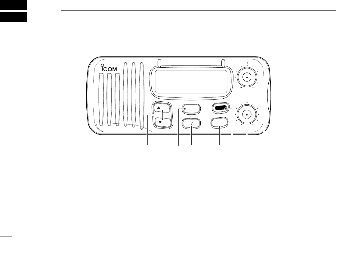
PANEL DESCRIPTION
■ Front panel
q CHANNEL UP/DOWN SWITCHES [YUP]/[ZDN]
Push to select an operating channel. (p. 6)
• Push and hold to ‘speed’ scroll up or down through the available
channels.
w SCAN SWITCH [SCAN • TAG]
➥ Push to start/stop scanning. (p. 9)
• Scan type can be selected in SET mode. (p. 12)
➥ Push for 1 sec. to toggle the tag setting for the displayed
channel. (p. 9)
e HIGH/LOW POWER SWITCH [H/L •
➥ Toggles between high and low output powers. (p. 8)
DIM]
➥ While pushing, push the [UP]/[DN] switches to adjust the
display backlighting. (p. 10)
➥ While pushing, push [SCAN] for 3 sec. to clear all tag
channels. (p. 9)
r CHANNEL SWITCH [CH •
DUAL]
➥ Push to selects the International channel group. (p. 6)
➥ The U.S.A. channel group is also available. To toggle
between international and U.S.A. channels, while pushing [H/L], push this switch.
2
Page 7

PANEL DESCRIPTION
HI/LO
➊
➋
2
t CHANNEL 16 SWITCH [16 • C]
➥ Push to select channel 16. (p. 5)
➥ Push for 1 sec. to select the call channel (the call chan-
nel number is different depend on version). (p. 5)
• Each group can have it’s own call channel programmed.
➥ Push for 3 sec. (when a call channel is selected) to enter
call channel write mode. (p. 10)
• Channel indication flashes.
y SQUELCH CONTROL [SQUELCH]
Rotate clockwise to eliminate audio noise. (p. 7)
u POWER/VOLUME CONTROL [PWR/VOL]
Turns power ON and OFF and adjusts the audio output
level.
■ Microphone
q CHANNEL UP/DOWN SWITCHES [Y]/[Z]
Select an operating channel in the selected channel group.
• These switches can be used instead of the transceiver’s
[UP]/[DN] switches.
w HIGH/LOW POWER SWITCH [HI/LO]
The same function as the transceiver’s [H/L] switch—toggles between high and low output powers.
• Pushing this key at power ON turns the microphone keys
ON/OFF.
3
Page 8
2
LOW
CALL
USA
INT
TX
TAG
DUAL
SCAN
DUP
TRI
BUSY
wq erty
u
i
o
!1
!0
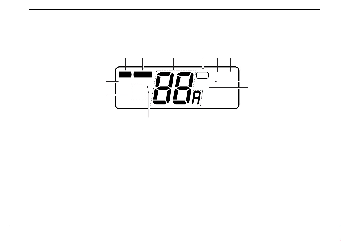
PANEL DESCRIPTION
■ Function display
q TRANSMIT INDICATOR
Appears while transmitting. (p. 8)
w BUSY INDICATOR
Appears when receiving a signal or when [SQUELCH] is
rotated too far clockwise. (p. 7)
e CHANNEL INDICATOR
Shows the operating channel (pgs. 5, 6)
r TAG CHANNEL INDICATOR
Appears when the selected channel is set as a tag channel. (p. 9)
t DUALWATCH INDICATOR
Appears and flashes during dualwatch operation. (p. 7)
y TRI-WATCH INDICATOR
Appears and flashes during tri-watch operation. (p. 7)
4
u SCAN INDICATOR
Appears and flashes during scan operation. (p. 9)
i DUPLEX INDICATOR
Appears when the selected channel is a duplex channel.
(p. 6)
o CALL CHANNEL INDICATOR
Appears when the call channel is selected. (p. 5)
!0 MODE INDICATORS (p. 5, 6)
➥ “USA” shows that USA channels are selected.
➥ “INT” shows that international channels are selected.
!1 LOW POWER INDICATOR
Shows that low output power is selected. (p. 8)
Page 9

BASIC OPERATION
LOW CALL
CANUSA
INT
ALTWX
TX
TAG
DUAL
SCAN
DUP ACK RCV
TRI
BUSY
All display indications
appear briefly.
Channel 16 is automatically
selected.
INT
USA
Push
16
INT
C
Push
for 1 sec. “CALL” indicates that the
call channel is selected.
16
C
CALL
USA
CC
3
■ Power ON
➀ Rotate [PWR/VOL] clockwise to turn power ON.
➁ Operate the transceiver as indicated in the following sec-
tions.
D Low voltage indicator
When “bAT” appears and flashes
as shown at right, there is a DC
power source problem. In this case,
check your vessel’s battery and DC
power cable.
■ Channel selection
D Channel 16
Channel 16 is the distress channel. It is used for establishing
initial contact with another station and for emergency communications. Channel 16 is monitored during dual/tri-watch.
While standing by you are required to monitor channel 16.
D Call channel
The call channel is used to store your most often-used channel for quick recall. In addition, the call channel is monitored
during tri-watch. The default setting for the call channel is
channel 16* which is for leisure boat use. A separate call
channel can be set for each channel group (USA and INT).
* The default call channel number is depends on version.
5
Page 10

3
D
CH
U
A
L
U
D
N
P
Push
then
INT
TAG
INT
TAG
DUP
Simplex channel
Used for ship-to-ship
communication
Duplex channel
Used for ship-to-coast
communication
BASIC OPERATION
D International channels
There are 55 international channels for the IC-M45EURO.
q Push [CH] to select an international channel.
w Push [UP]/[DN] to select a channel.
• “DUP” appears for duplex channels.
The previously selected channel is recalled by the [CH]
switch directory from channel 16 or the call channel.
However, once push the channel [UP]/[DN] switch from
channel 16 or the call channel, the previously selected
channel cannot be recalled in this manner.
6
Page 11

BASIC OPERATION
USA
DUAL
USA
DUAL
BUSY
Checking channel 16
every 2 sec.
When receiving a signal
on channel 16. Channel
16 is monitored until the
signal disappears.
USA
TRI
CALL
USA
TRI
BUSY
USA
TRI
BUSY
Checking channel 16
and the call channel
every 2 sec.
When receiving a signal
on channel 16, channel
16 has priority.
When receiving a signal
on the call channel, the
call channel is monitored
while checking ch 16 in
2 sec. intervals.
3
■ Receiving
➀ Rotate [PWR/VOL] to turn power ON.
➁ Rotate [SQUELCH] fully counterclockwise.
➂ Adjust [PWR/VOL] to a suitable listening level.
➃ Rotate [SQUELCH] clockwise until the audio noise disap-
pears.
➄ Select a channel. See pgs. 5–6 for details.
• When a signal is received:
➧ The squelch opens.
➧ Audio is emitted from the speaker.
➧ “BUSY” appears in the function display.
➅ When an interrupting signal is received, rotate [SQUELCH]
deeply clockwise.
D Dual/tri-watch functions
These functions allow you to conveniently check the distress
channel (ch 16) or, both the distress and leisure call channel
(ch 9; programmable) while receiving another channel. When
receiving a signal on one of these channels, the transceiver
stops on the channel until the signal disappears.
Depending on your preference, select dual watch or tri-watch
in advance in SET mode (p. 12). Dual watch is the default
setting.
When dual watch is selected in SET mode:
➥ Push [CH •
] for 1 sec. to start dual watch.
DUAL
When tri-watch is selected in SET mode:
➥ Push [CH •
DUAL] for 1 sec. to start tri-watch.
➥ Push any switch to cancel dual/tri-watch and return to nor-
mal operation.
7
Page 12

3
BASIC OPERATION
■ Transmitting
Before transmitting, read the call procedures at right.
➀ Select an operating channel. See pgs. 5–6 for details.
➁ Push [H/L] to select a transmit output power.
• “LOW” appears when low output power is selected.
• High power cannot be selected on some channels. Refer to the
channel list on p. 18.
➂ Push and hold the [PTT] switch to transmit.
•“$” appears.
➃ Speak into the microphone at your normal voice level.
• Do not hold the microphone too closely to your mouth or speak to
loudly. This may distort the signal.
➄ Release the [PTT] switch to receive.
IMPORTANT: In order to maximize the readability of
your transmitted signal, pause for a moment after pushing
[PTT], hold the microphone 15–20 cm from your mouth,
then speak into the microphone at an even, normal voice
level.
CALL PROCEDURES
You must identify yourself when you transmit and you must
respect time limits.
1) Give your call sign each time you call another vessel or
a coast station. If you have no call sign, identify the station by giving the vessel name and the name of the license.
2) Give your call sign at the end of each transmission that
lasts more than 3 minutes.
3) You must pause and give your call sign at least once
every 15 minutes during long ship-to-shore calls.
4) Keep your calls short (less than 3 minutes). Wait 2 minutes before repeating a call.
8
Page 13

BASIC OPERATION
USA
TAG
Appears when the channel is
specified as a tag channel.
3
■ Scan function
The transceiver has a high speed scan function for standing
by on utility signals. The scan speed is 8 channel/sec. (except when the weather alert function is in use).
Two scan types are available: normal scan (scans all tag
channels in sequence) and priority scan (checks channel 16
while scanning). These scans can be selected in SET mode
(p. 12).
D Setting tag channels
You can specify channels as tag channels for efficient scanning. Tag channels can be set for each channel group (USA,
INT) independently.
➥ Select the desired channel, then push [
sec. to toggle the tag setting.
✔ Clearing all tag channels
While pushing [H/L], push [SCAN • TAG] for 3 sec. until the
long beep becomes 2 short beeps.
• All tag channels in the selected channel group are released.
SCAN • TAG] for 1
D Scan operation
➀ Be sure the squelch is set to the threshold point.
➁ Push [SCAN] to start scanning.
• “SCAN” appears and flashes in the function display.
• “16” appears during priority scan.
➂ To stop the scan, push [SCAN] again.
• “SCAN” disappears.
✔ Scan resume timer
When a signal is detected, scan pauses until the signal disappears or resumes after pausing 5 sec., according to the
SET mode setting. (p. 12)
✔ Confirming tag channels
While operating scan, push [UP] or [DN].
• Only tag channels are selected.
• Stop pushing [UP] or [DN] to resume scan.
9
Page 14

3
USA
CALL
USA
TAG
CALL
USA
CALL
USA
CALL
USA
BASIC OPERATION
10
■ Call channel programming
Pushing [16 • C] for 1 sec. selects the call channel, channel
16 by default, however you can program your most oftenused channels in each channel group for quick recall.
➀ Push [16 • C] for 1 sec. to se-
lect the call channel of the selected group.
• “CALL” and the call channel
number appear.
➁ Push [16 • C] for 3 sec. to
enter call channel write mode.
• Call channel and channel group
to be programmed flash.
➂ Push [UP] or [DN] to select
the desired channel.
➃ Push any switch to automati-
cally program the selected
channel.
• The transceiver returns to nor-
mal operation.
■ Display backlighting
The function display and switches can be backlit for better
visibility under low light conditions.
While pushing [H/L •
backlighting.
• Backlighting can be set to 1 of 4 intensities or turned OFF.
DIM], push [UP] or [DN] to adjust the
Page 15

SET MODE
Beep tones (p. 12)
*
1
*
2
Normal/priority
scan (p. 12)
Scan timer (p. 12)
Dual/tri-watch (p. 12)
Select a
SET mode
item*
2
Select a
SET mode
condition*
1
16
U
D
N
P
*
1
*
2
*
1
*
2
*
1
*
2
4
■ Entering SET mode
SET mode is used to customize operation of the transceiver
to suit your operating needs.
D To enter SET mode:
➀ While pushing [16], turn power ON.
• Keep pushing [16] until the initial SET mode display appears.
• SET mode is selected.
➁ To exit SET mode, turn power OFF then ON again.
D To select an item:
There are 5 items in SET mode that may be adjusted to suit
your operating needs.
➀ Select SET mode as above.
➁ Push [16] to select an item; then push [UP]/[DN] to set the
condition for the item.
■ SET mode items
SET mode items above are shown at their
default conditions.
11
Page 16

4
Beep tones ON (default)
Beep tones OFF
Priority scan (default)
Normal scan
Scan timer OFF (default) Scan timer ON
• Scan pauses on a signal
and resumes 5 sec. later.
• Scan pauses on a signal
until the signal disappears,
and resumes 3 sec. after
that.
Dual watch (default) Tri-watch
SET MODE
D BEEP TONES
This item sets the transceiver’s confirmation beep tones
(when pushing a switch) ON or OFF.
D NORMAL/PRIORITY SCAN
This item sets the scan function to normal or priority operation. (See p. 9)
D DUAL/TRI-WATCH
This item sets the [CH • DUAL] switch to activate dual watch
or tri-watch. (p. 7)
D SCAN TIMER
This item sets the scan timer ON or OFF.
12
Page 17

CONNECTIONS AND MAINTENANCE
➀➂
➁➃
➄
➅
➆
➇
5
■ Unpacking
➀ Mounting bracket ............................................................ 1
➁ DC power cable (OPC-632) ............................................ 1
➂ Microphone hanger ......................................................... 1
➃ Mounting bracket knobs .................................................. 2
➄ Mounting screws (5 × 20) ................................................ 2
➅ Mic hanger screws (3.5 × 30) .......................................... 2
➆ Flat washers (M5) ........................................................... 2
➇ Spring washers (M5) ....................................................... 2
■ Antenna
A key element in the performance of any communication system is an antenna. Ask your Dealer about antennas and the
best places to mount them.
■ Fuse replacement
Two fuses are installed in the supplied DC power cable. If a
fuse blows or the transceiver stops functioning, track down
the source of the problem, if possible, and replace the damaged fuse with a new, rated one.
☛ Fuse rating: 10 A
■ Cleaning
If the transceiver becomes dusty or dirty, wipe it clean with a
dry, soft cloth.
AVOID the use of solvents such as benzene or alcohol, as they may damage transceiver surfaces.
13
Page 18

5
q
wr
e
CONNECTIONS AND MAINTENANCE
■ Connections
14
q DC POWER CONNECTOR
Connects the supplied DC power cable from this connector
to an external 12 V DC power source.
w ANTENNA CONNECTOR
Connects a marine VHF antenna with a PL-259 connector
to the transceiver.
CAUTION: Transmitting without an antenna will damage
the transceiver.
e EXTERNAL SPEAKER JACK
Connects to an external speaker. See OPTIONS on p. 19
for available external speakers
r MICROPHONE HANGER
Rest the microphone on the hanger when not in use.
Page 19

CONNECTIONS AND MAINTENANCE
5
■ Mounting the transceiver
The universal mounting bracket supplied with your transceiver
allows overhead or dashboard mounting. Please read the following instructions carefully.
• Mount the transceiver securely with the 2 supplied screws
(M5 × 20) to a surface which is more than 10 mm thick and
can support more than 5 kg.
• Mount the transceiver so that the face of the transceiver is at
90° to your line of sight when operating it.
CAUTION: KEEP the transceiver and microphone at
least 1 meter away from your vessel’s magnetic navigation compass.
☞ NOTE: Check the installation angle; the function display
may not be easy to read at some angles.
DASHBOARD MOUNTING (with optional MB-69)
OVERHEAD MOUNTING
15
Page 20

5
152 mm (6 in)
178 mm (7 in)
67 mm (2
5
⁄8 in)
51 mm (2 in)
28.5 mm
(1⁄8 in)
86.5 mm (3 13⁄32 in) 25 mm
(1 in)
CONNECTIONS AND MAINTENANCE
■ Dimensions
16
Page 21

PROBLEM POSSIBLE CAUSE SOLUTION REF.
No power comes on. • Power cord not connected properly.
• Blown fuse.
No sound comes from the
speaker.
No beeps sound even when a
switch is pushed.
Sensitivity is low and only
strong signals are audible.
Transmitting is impossible or
high power cannot be
selected.
• [SQUELCH] is rotated too far clockwise. • Rotate [SQUELCH] counterclockwise to a
• Beep function is turned OFF. • Set beeps to ON in SET mode. p. 12
• [SQUELCH] is rotated too far clockwise.
• Antenna feedline or the antenna connector
solder has poor contact or is short circuited.
• Transmission is restricted on some channels. • Change channels. p. 18
TROUBLESHOOTING
• Check the power cord connection.
• Check the polarity of the power connection,
then, replace the fuse.
suitable position.
• Rotate [SQUELCH] counterclockwise to a
suitable position.
• Check, and if necessary, replace the feedline or
solder the antenna connector again.
6
p. 14
p. 13
p. 7
p. 7
p. 14
Desired channel cannot be
selected.
No display backlighting. • Backlight function is turned OFF. • While pushing [H/L
Scan does not start. • No “TAG” channels are programmed. • Set channels to be scanned as “TAG” channels. p. 9
• Different channel group is selected. • Push [CH] to select the appropriate
channel group .
• DIM], push [UP]/[DN] to
select the desired brightness.
p. 6
p. 10
17
Page 22

7
VHF MARINE CHANNEL LIST
ï International channels
Frequency (MHz)
CH
Transmit
156.100 160.700
02
156.150 160.750
156.200 160.800
04
156.250 160.850
156.300 156.300
06
156.350 160.950
07
156.400 156.400
08
156.450 156.450
09
156.500 156.500
10 156.575
Receive
Frequency (MHz)
CH
Transmit
156.550 156.550156.050 160.650
11
156.600 156.600
12
156.650 156.650
13
156.700 156.700
14
1
156.750 156.750
15*
156.800 156.800
16
156.850 156.850
17
156.900 161.500
18
156.950 161.550
19
157.000 161.600
20
Receive
Frequency (MHz)
CH
Transmit
157.050 161.650
21
157.100 161.700
22
157.150 161.750
23
157.200 161.800
24
157.250 161.850
25
157.300 161.900
26
157.350 161.950
27
157.400 162.000
28
156.025 160.625
60
156.075 160.675
61
Receive
Frequency (MHz)
CH
Transmit
156.125 160.725
62
156.175 160.775
63
156.225 160.825
64
156.275 160.875
65
156.325 160.925
66
156.375 156.375
67
156.42501156.425
68
156.47503156.475
69
2
156.52505156.525
70*
156.575
71
Receive
Frequency (MHz)
CH
Transmit
156.625 156.625
72
156.675 156.675
73
156.725 156.725
74
156.875 156.875
77
156.925 161.525
78
156.975 161.575
79
157.025 161.625
80
157.075 161.675
81
157.125 161.725
82
157.175 161.775
83
*1 Low power only *2 Receive only
Receive
CH
84
85
86
87
88
Frequency (MHz)
Transmit
157.225 161.825
157.275 161.875
157.325 161.925
157.375 161.975
157.425 162.025
Receive
18
Page 23

SPECIFICATIONS AND OPTIONS
8
■ Specifications
General
• Frequency coverage : Transmit 156–157.5 MHz
Receive 156–163 MHz
• Usable channels : All International channels
• Mode : 16K0G3E
• Power supply requirement : 13.8 V DC ±15% (negative ground)
• Current drain : Transmit
(at 13.8 V DC) high power 6.0 A
Receive
max. audio output 1.2 A
• Frequency stability : ±1.5 KHz
• Usable temperature range : –20°C to +60°C; –4°F to +140°F
• Dimensions : 152(W) × 67(H) × 144(D) mm
(projections not included) 6(W) × 2
• Weight : 900 g; 2 lb
Transmitter
• Output power : High 25 W Low 1 W
• Modulation system : Variable reactance
frequency modulation
• Max. frequency deviation : ±5 kHz
• Spurious emissions : Less than –70 dB
• Microphone impedance : 600 Ω
(–20°C to +60°C)
5
(H) × 5
⁄8
2
⁄3
(D) in
Receiver
• Receive system : Double-conversion
superheterodyne
• Intermediate frequencies : 1st 30.85 MHz
2nd 450 kHz
• Sensitivity : 0.3 µV
• Intermodulation rejection : More than 68 dB
• Adjacent channel selectivity : More than 70 dB
• Spurious response rejection ratio : More than 70 dB
• Audio output power : More than 2 W at 10%
(at 13.8 V DC) distortion with a 4 Ω load
• Audio output impedance : 4 Ω
at 12 dB SINAD
■ Options
MB-69 FLUSH MOUNT
For mounting the IC-M45EURO to a panel. Available in black
or white.
SP-5 EXTERNAL SPEAKER
A large, external speaker for superior audio output.
SP-10 EXTERNAL SPEAKER
A compact, external speaker. Features easy installation.
19
Page 24

Count on us!
A-5485D-1EU-w
Printed in Japan
© 1997 Icom Inc.
6-9-16 Kamihigashi, Hirano-ku, Osaka 547-0002 Japan
 Loading...