

Page 1

INSTRUCTION MANUAL
VHF MARINE TRANSCEIVER
iM421
Page 2
FOREWORD
WORD
DEFINITION
RWARNING
CAUTION
NOTE
Personal injury, fire hazard or electric shock
may occur.
If disregarded, inconvenience only. No risk
of personal injury, fire or electric shock.
Equipment damage may occur.
IMPORTANT
Thank you for purchasing this Icom product. The IC-M421
VHF MARINE TRANSCEIVER
state of the art technology and craftsmanship. With proper
care, this product should provide you with years of troublefree operation.
We want to take a couple of moments of your time to thank
you for making the IC-M421 your radio of choice, and hope
you agree with Icom’s philosophy of “technology first.” Many
hours of research and development went into the design of
your IC-M421.
D
❍ Built-in DSC meets ITU Class D require-
❍ Superior receiver performance
❍ Large 2-digit Ch with scrolling channel
❍ Rugged waterproof construction
❍ Easy to hear speaker
Icom, Icom Inc. and the logo are registered trademarks of Icom Incorporated (Japan) in the United States, the United Kingdom, Germany, France,
Spain, Russia and/or other countries.
i
is designed and built with Icom’s
FEATURES
ment
comment
READ ALL INSTRUCTIONS carefully and completely
before using the transceiver.
SAVE THIS INSTRUCTION MANUAL — This in-
struction manual contains important operating instructions for
the IC-M421.
EXPLICIT DEFINITIONS
CLEAN THE TRANSCEIVER AND MICROPHONE THOROUGHLY WITH FRESH WATER after exposure to water
including salt water, otherwise, the keys and switches may
become inoperable due to salt crystallization.
Page 3

IN CASE OF EMERGENCY
INSTALLATION NOTE
If your vessel requires assistance, contact other vessels and
the Coast Guard by sending a distress call on Channel 16.
USING CHANNEL 16
DISTRESS CALL PROCEDURE
1. “MAYDAY MAYDAY MAYDAY.”
2. “THIS IS ...............” (name of vessel)
3. Your call sign or other indication of the vessel (AND 9digit DSC ID if you have one).
4. “LOCATED AT ...............” (your position)
5. The nature of the distress and assistance required.
6. Any other information which might facilitate the rescue.
Or, transmit your distress call using digital selective calling on
Channel 70.
USING DIGITAL SELECTIVE CALLING (Ch 70)
DISTRESS CALL PROCEDURE
1. While lifting up the key cover, push and hold
[DISTRESS] for 5 sec. until you hear 5 short beeps
change to one long beep.
2. Wait for an acknowledgment on Channel 70 from a
coast station.
• After the acknowledgment is received, Channel 16 is
automatically selected.
3. Push and hold [PTT], then transmit the appropriate
information as listed above.
The installation of this equipment should be made in such a
manner as to respect the EC recommended electromagnetic
field exposure limits (1999/519/EC).
The maximum RF power available from this device is 25
watts. The antenna should be installed as high as possible
for maximum efficiency and that this installation height should
be at least 5 meters above ground (or accessible) level. In the
case where an antenna cannot be installed at a reasonable
height, then the transmitter should neither be continuously
operated for long periods if any person is within 5 meters of
the antenna, nor operated at all if any person is touching the
antenna.
In all cases any possible risk depends on the transmitter
being activated for long periods. (actual recommendation limits are specified as an average of 6 minutes) Normally the
transmitter is not active for long periods of time. Some radio licenses will require that a timer circuit automatically cuts the
transmitter after 1–2 minutes etc.
Similarly some types of transmitter, SSB, CW, AM, etc. have a
lower ‘average’ output power and the perceived risk is even
lower.
ii
Page 4
DOC
DECLARATION
OF CONFORMITY
We Icom Inc. Japan
1-1-32, Kamiminami, Hirano-ku
Osaka 547-0003, Japan
Kind of equipment:
VHF MARINE TRANSCEIVER
This compliances is based on conformity with the following harmonised
standards, specifications or documents:
i)
EN 301 025-2 V1.2.1 (2004-09)
ii)
EN 301 025-3 V1.2.1 (2004-09)
iii) EN 60945 2002
iv) EN 60950-1 2001
v) EN 300 698-2 V1.1.1 ( 2000-08)
vi) EN 300 698-3 V1.1.1 ( 2001-05)
Type-designation: iM421
Signature
Declare on our sole responsibility that this equipment complies with the
essential requirements of the Radio and Telecommunications Terminal
Equipment Directive, 1999/5/EC, and that any applicable Essential Test
Suite measurements have been performed.
Version (where applicable):
0560
Authorized representative name
Place and date of issue
8th Mar. 2006
CE versions of the IC-M421 which display the
“CE” symbol on the serial number seal, comply with the essential requirements of the European Radio and Telecommunication
Terminal Directive 1999/5/EC.
This warning symbol indicates that this equipment operates in non-harmonised frequency
bands and/or may be subject to licensing conditions in the country of use. Be sure to check that
you have the correct version of this radio or the
correct programming of this radio, to comply with
national licensing requirement.
iii
Page 5

TABLE OF CONTENTS
FOREWORD …………………………………………………………… i
IMPORTANT …………………………………………………………… i
EXPLICIT DEFINITIONS ……………………………………………… i
IN CASE OF EMERGENCY…………………………………………… ii
INSTALLATION NOTE ………………………………………………… ii
DOC …………………………………………………………………… iii
TABLE OF CONTENTS ……………………………………………… iv
PRECAUTION ………………………………………………………… v
1 OPERATING RULES ……………………………………………… 1
2 PANEL DESCRIPTION ………………………………………… 2–5
■ Panel description………………………………………………… 2
■ Function display ………………………………………………… 4
■ Microphone ……………………………………………………… 5
3 BASIC OPERATION ………………………………………… 6–10
■ Channel selection ……………………………………………… 6
■ Receiving and transmitting……………………………………… 8
■ Call channel programming……………………………………… 9
■ Channel comments …………………………………………… 10
■ Microphone lock function ……………………………………… 10
■ Display backlighting …………………………………………… 10
4 DUALWATCH/TRI-WATCH ……………………………………… 11
■ Description ……………………………………………………… 11
■ Operation ……………………………………………………… 11
5 SCAN OPERATION ………………………………………… 12–13
■ Scan types ……………………………………………………… 12
■ Setting tag channels …………………………………………… 13
■ Starting a scan ………………………………………………… 13
6 DSC OPERATION …………………………………………… 14–44
■ MMSI code programming……………………………………… 14
■ MMSI code check ……………………………………………… 15
■ DSC individual ID ……………………………………………… 16
■ Position and time programming ……………………………… 20
■ Position and time indication…………………………………… 21
■ Distress call …………………………………………………… 22
■ Transmitting DSC calls ………………………………………… 25
■ Receiving DSC calls …………………………………………… 37
■ Received messages …………………………………………… 41
■ DSC Set mode ………………………………………………… 43
7 SET MODE …………………………………………………… 45–46
■ Set mode programming ……………………………………… 45
■ Set mode items ………………………………………………… 45
8 CONNECTIONS AND MAINTENANCE …………………… 47–50
■ Supplied accessories ………………………………………… 47
■ Antenna ………………………………………………………… 47
■ Fuse replacement ……………………………………………… 47
■ Cleaning ………………………………………………………… 47
■ Connections …………………………………………………… 48
■ Mounting the transceiver ……………………………………… 49
■ Optional MB-69 installation …………………………………… 50
9 TROUBLESHOOTING …………………………………………… 51
10 CHANNEL LIST ……………………………………………… 52–53
11 SPECIFICATIONS AND OPTION ……………………………… 54
■ Specifications …………………………………………………… 54
■ Option …………………………………………………………… 54
12 TEMPLATE ……………………………………………………… 55
DIMENSIONS ………………………………………………………… 57
iv
Page 6

PRECAUTION
RWARNING! NEVER connect the transceiver to an AC
outlet. This may pose a fire hazard or result in an electric
shock.
NEVER connect the transceiver to a power source of more
than 16 V DC or use reverse polarity. This will ruin the transceiver.
NEVER cut the DC power cable between the DC plug and
fuse holder. If an incorrect connection is made after cutting,
the transceiver may be damaged.
NEVER place the transceiver where normal operation of the
vessel may be hindered or where it could cause bodily injury.
KEEP the transceiver at least 1 m away from the ship’s nav-
igation compass.
DO NOT use or place the transceiver in areas with temper-
atures below –20°C or above +60°C or in areas subject to direct sunlight, such as the dashboard.
AVOID the use of chemical agents such as benzine or al-
cohol when cleaning, as they may damage the transceiver
surfaces.
BE CAREFUL! The transceiver rear panel will become
hot when operating continuously for long periods.
Place the transceiver in a secure place to avoid inadvertent
use by children.
BE CAREFUL! The transceiver and HM-150 employs wa-
terproof construction, which corresponds to JIS waterproof
specification, Grade 7 (1 m/30 min.). However, once the
transceiver or microphone has been dropped, waterproofing
cannot be guaranteed due to the fact that the case may be
cracked, or the waterproof seal damaged, etc.
v
Page 7

OPERATING RULES
1
DD
PRIORITIES
• Read all rules and regulations pertaining to priorities and
keep an up-to-date copy handy. Safety and distress calls
take priority over all others.
• You must monitor Channel 16 when you are not operating
on another channel.
• False or fraudulent distress signals are prohibited and punishable by law.
DD
PRIVACY
• Information overheard but not intended for you cannot lawfully be used in any way.
• Indecent or profane language is prohibited.
DD
RADIO LICENSES
(1) SHIP STATION LICENSE
You must have a current radio station license before using the
transceiver. It is unlawful to operate a ship station which is not
licensed.
Inquire through your dealer or the appropriate government
agency for a Ship-Radiotelephone license application. This
government-issued license states the call sign which is your
craft’s identification for radio purposes.
(2) OPERATOR’S LICENSE
A Restricted Radiotelephone Operator Permit is the license
most often held by small vessel radio operators when a radio
is not required for safety purposes.
The Restricted Radiotelephone Operator Permit must be
posted or kept with the operator. Only a licensed radio operator may operate a transceiver.
However, non-licensed individuals may talk over a transceiver
if a licensed operator starts, supervises, ends the call and
makes the necessary log entries.
Keep a copy of the current government rules and regulations
handy.
1
1
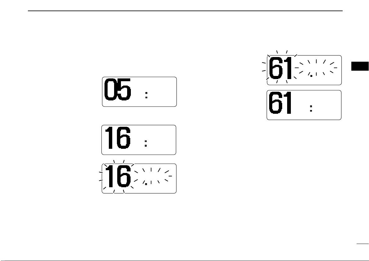
Page 8
2
Function
display (p. 4)Speaker
qi!0o
weuytr
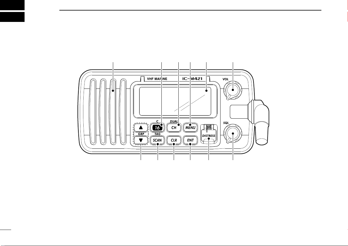
PANEL DESCRIPTION
■ Panel description
q POWER/VOLUME CONTROL [VOL] (p. 8)
➥ Rotate to turn the transceiver power ON or OFF.
➥ Rotate to adjust the audio level.
w SQUELCH CONTROL [SQL] (p. 8)
Rotate to set the squelch threshold level.
2
e DISTRESS KEY [DISTRESS] (p. 22)
Transmits a distress call when pushed for 5 sec.
r ENTER KEY [ENT]
Sets the DSC menu, a channel comment, etc. when
pushed.
t CLEAR KEY [CLR]
Cancels the entered function and exits the condition when
pushed.
Page 9

PANEL DESCRIPTION
2
y SCAN/TAG CHANNEL KEY [SCAN•TAG] (p. 13)
➥ Push to start and stop the normal or priority scan when
tag channels are programmed.
➥ Push for 1 sec. to set the displayed channel as a tag
(scanned) channel.
➥ While pushing [HI/LO] located on the microphone, push
for 3 sec. to clear or set all tag channels in the selected
channel group.
u CHANNEL UP/DOWN KEYS [▲]/[▼]•[U/I]
➥ Selects the operating channels, Set mode settings, etc.
when pushed. (pgs. 6, 45)
➥ Selects one of two channel groups in sequence when
both keys are pushed. (p. 7)
• International and U.S.A.* channels are available.
(*U.K. version only)
➥ While pushing [SCAN•TAG], push to adjust the bright-
ness of the LCD and key backlight. (p. 10)
i CHANNEL 16/CALL CHANNEL KEY [16•C]
➥ Selects Channel 16 when pushed. (p. 6)
➥ Selects call channel when pushed for 1 sec. (p. 6)
➥ Push for 3 sec. to enter the call channel programming
condition when the call channel is selected. (p. 9)
➥ While pushing [CH•DUAL], push to enter the channel
comment programming condition. (p. 10)
➥ While turning power ON, push to enter set mode. (p. 45)
o CHANNEL/DUALWATCH/TRI-WATCH KEY [CH•DUAL]
➥ Push to select the regular channel. (pgs. 6, 7)
➥ Push for 1 sec. to start dualwatch or tri-watch. (p. 11)
➥ Push to stop dualwatch or tri-watch when either is acti-
vated. (p. 11)
!0 DSC MENU KEY [MENU] (p. 14)
Toggles the DSC menu ON or OFF when pushed.
2
3
Page 10
2 PANEL DESCRIPTION
BUSY-INT----
25W-DUP-TAG-
NORMAL-SCAN-
23 34.154N-
135 34.351E-
-CALLING UTC-12:00-
qw y
u
e
i
o
!1 !0
tr
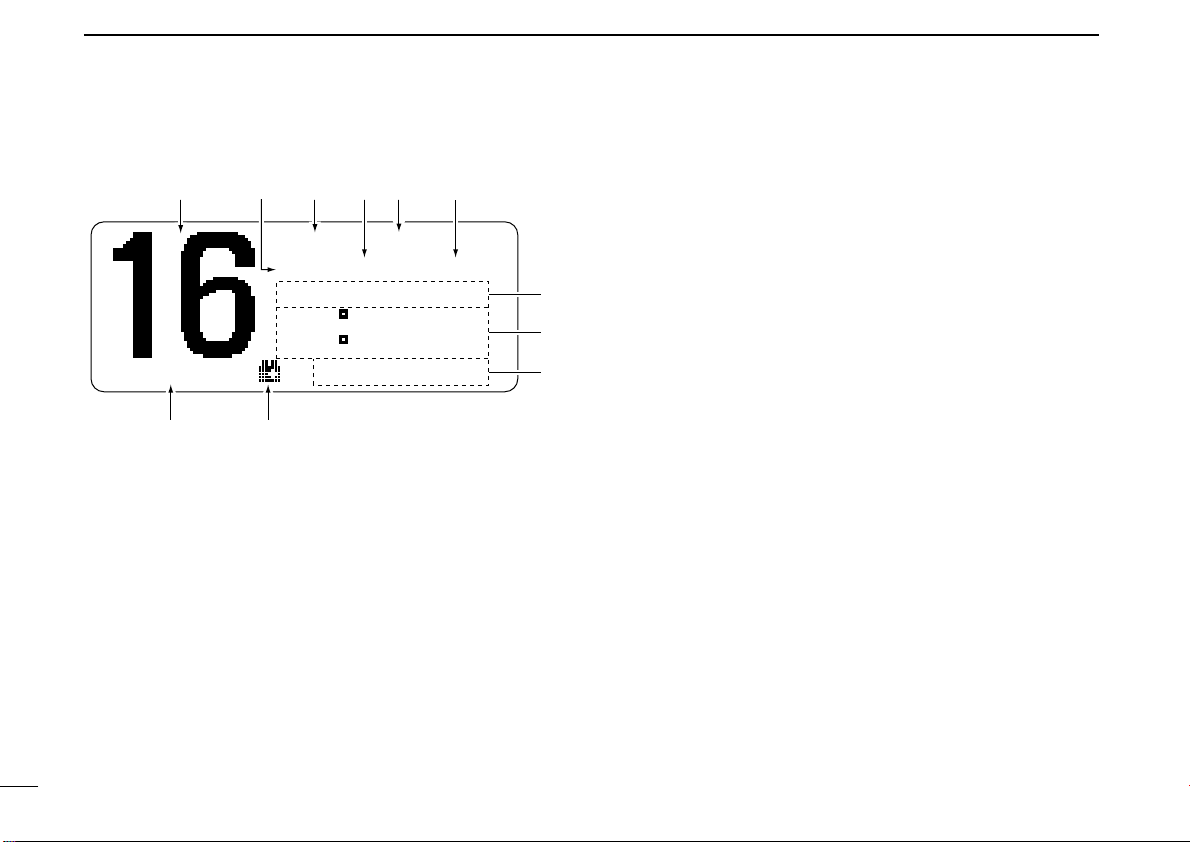
■ Function display
q CHANNEL NUMBER READOUT
Indicates the selected operating channel number.
• “A” appears when a simplex channel is selected. (p. 7)
w POWER INDICATOR (p. 8)
➥ “25W” appears when high power is selected.
➥ “1W” appears when low power is selected.
e BUSY/TRANSMIT INDICATOR (p. 8)
➥ “BUSY” appears when receiving a signal or when the
squelch opens.
➥ “TX” appears while transmitting.
4
r DUPLEX INDICATOR (p. 7)
Appears when a duplex channel is selected.
• Duplex channel has a different transmit frequency and receiving
frequency.
t CHANNEL GROUP INDICATOR (p. 7)
Indicates whether an International “INT” or U.S.A. “USA”
channel is selected. (depends on version)
y TAG CHANNEL INDICATOR (p. 13)
Appears when a tag channel is selected.
u SCAN INDICATOR
➥ Either “NORMAL SCAN” or “PRI-SCAN 16” scan
type appears while scanning. (p. 13)
➥ “DUAL 16” appears during dualwatch; “TRI 16” ap-
pears during tri-watch. (p. 11)
i POSITION INDICATOR
➥ Shows the GPS position data.
•“??” may blink every 2 sec. instead of position data; when the
GPS position data is invalid. In such a case, the last position
data is held for up to 23.5 hours.
•“??” may blink every 2 sec. instead of position data 4 hours
after the position data is input manually, up until 23.5 hours
have past.
• A beep sounds automatically for 1 min. every 4 hours when
the GPS or manually input position data has not been updated.
➥ “No Position” appears when no GPS receiver is
connected and no position data is input manually.
Page 11
o TIME ZONE INDICATOR
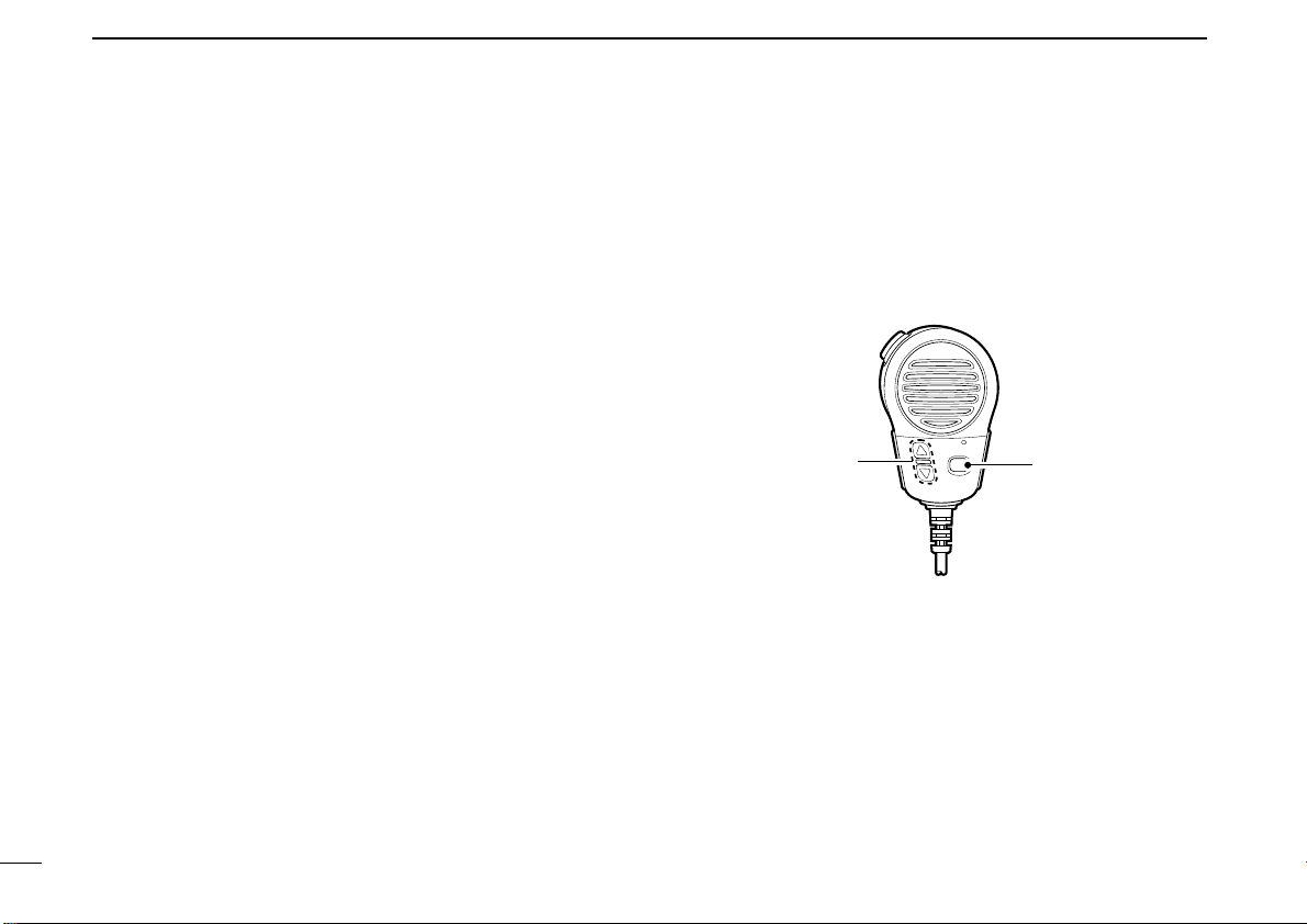
Microphone
w
q
e
➥ Shows the current time data when a GPS receiver is
connected.
➥ “No Time” appears when no GPS receiver is con-
nected and no time data is input manually.
➥ “Local” appears when the offset time data is set.
(p. 43)
!0 LOW BATTERY INDICATOR
“ ” blinks when the battery voltage drops to approx. 11 V
DC or below.
!1 CHANNEL COMMENT INDICATOR
Channel comment appears if programmed. (p. 10)
• More than 9-character comment scrolls automatically.
PANEL DESCRIPTION
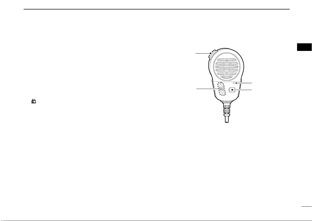
■ Microphone
q PTT SWITCH [PTT]
Push and hold to transmit; release to receive. (p. 8)
2
2
w CHANNEL UP/DOWN KEYS [JJ]/[KK]
Push either key to change the operating memory channel,
set mode settings, etc. (pgs. 6, 45)
e TRANSMIT POWER KEY [HI/LO]
➥ Toggles power high and lower when pushed. (p. 8)
• Some channels are set to low power only.
➥ While pushing [HI/LO], turn power ON to toggle the mi-
crophone lock function ON and OFF. (p. 10)
5
Page 12

3
Push
for 1 sec.
-INT----
25W--TAG-
-
23 34.154N-
135 34.351E-
CALLING - UTC-12:00-
Push
-INT----
25W--TAG-
-
23 34.154N-
135 34.351E-
CALLING - UTC-12:00-
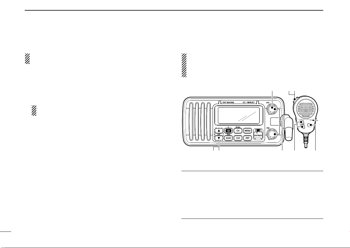
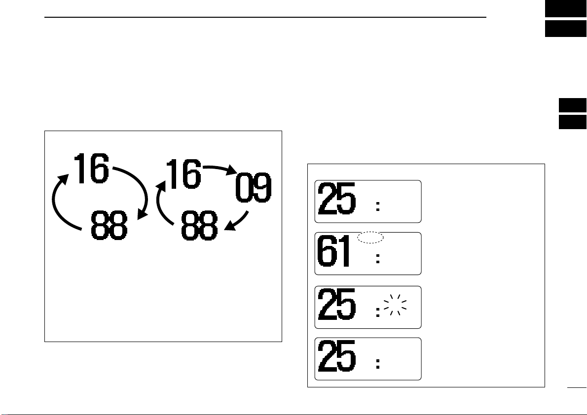
BASIC OPERATION
■ Channel selection
6
DD
Channel 16
Channel 16 is the distress and safety channel. It is used for
establishing initial contact with another station and for emergency communications. Channel 16 is monitored during both
dualwatch and tri-watch. While standing by, you must monitor
Channel 16.
➥ Push [16•C] momentarily to select Channel 16.
➥ Push [CH•DUAL] to return to the condition before selecting
Channel 16, or push [▲] or [▼] to select operating channel.
DD
Call channel
Each regular channel group has a separate leisure-use call
channel. The call channel is monitored during tri-watch. The
call channels can be programmed (p. 9) and are used to store
your most often used channels in each channel group for
quick recall.
➥ Push [16•C] for 1 sec. to select the call channel of the se-
lected channel group.
• The call channel number appears.
• Each channel group may have an independent call channel after
programming a call channel.
➥ Push [CH•DUAL] to return to the condition before selecting
the call channel, or push [▲] or [▼] to select an operating
channel.
Page 13
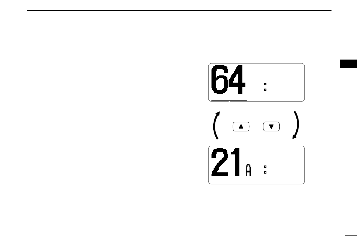
DD
Push both
and
U.S.A. channel*
International channel
-INT----
25W-DUP-TAG-
-
23 34.154N-
135 34.351E-
TELEPHON- UTC-12:00-
-USA----
25W--TAG-
-
23 34.154N-
135 34.351E-
- CCG - UTC-12:00-
Scrolls
International channels and U.S.A. channels*
The IC-M421 is pre-programmed with 57 International (INT)
channels in addition to 59 U.S.A. channels*. These channel
groups may be specified for the operating area.
q Push [CH•DUAL] to select a regular channel.
w Push both [▲] and [▼] on the transceiver to change the
channel group, if necessary.
• International and U.S.A.* channels can be selected in sequence.
e Push [▲] or [▼] to select a channel.
•“DUP” appears for duplex channels.
• “A” appears when a simplex channel is selected.
*U.K. version only
BASIC OPERATION
3
3
7
Page 14
3 BASIC OPERATION
u
w
re
M
q
y
r
t
M: Microphone
■ Receiving and transmitting
CAUTION: Transmitting without an antenna may damage
the transceiver.
q Rotate [VOL] to turn power ON.
w Set the audio and squelch levels.
➥ Rotate [SQL] fully counterclockwise in advance.
➥ Rotate [VOL] to adjust the audio output level.
➥ Rotate [SQL] clockwise until the noise disappears.
While in the DSC operation, please make sure you set
the squelch correctly.
e To change the channel group, push both [▲] and [▼] on
the transceiver. (p. 7)
r Push [▲] or [▼] to select the desired channel. (pgs. 6, 7)
• When receiving a signal, “BUSY” appears and audio is emitted
from the speaker.
• Further adjustment of [VOL] may be necessary at this point.
t Push [HI/LO] on the microphone to select the output
power if necessary.
•“25W” or “1W” appears when high or low power is selected, re-
spectively.
• Choose low power for short range communications, and choose
high power for longer distance communications.
• Some channels are for low power only.
y Push and hold [PTT] to transmit, then speak into the mi-
crophone (M).
•“TX” appears.
• Channel 70 cannot be used for transmission other than DSC.
u Release [PTT] to receive.
IMPORTANT: To maximize the readability of your trans-
mitted signal, pause a few sec. after pushing [PTT], hold
the microphone (M) 5 to 10 cm from your mouth and speak
at a normal voice level.
✔ NOTE for TOT (Time-out Timer) function
The TOT function inhibits continuous transmission over a preset time period after the transmission starts.
A beep sounds 10 sec. before the TOT function activates, to
indicate the transmission will be shut down and “TOT” ap-
pears on the channel comment indicator. Transmission is not
possible for 10 sec. after this transmission shut down.
8
Page 15
■ Call channel programming
-INTINT----
25W25W-DUPDUP-TAGTAG-
-
2323 34.154N34.154N-
135135 34.351E34.351E-
- INTLINTL - UTCUTC-12:0012:00-
-INTINT----
25W25W--TAGTAG-
CALLCALL WRITEWRITE -
2323 34.154N34.154N-
135135 34.351E34.351E-
- INTLINTL - UTCUTC-12:0012:00-
CALLCALL WRITEWRITE
-INTINT----
25W25W--TAGTAG-
-
2323 34.154N34.154N-
135135 34.351E34.351E-
CALLINGCALLING - UTCUTC-12:0012:00-
-INTINT----
25W25W--TAGTAG-
CALLCALL WRITEWRITE -
2323 34.154N34.154N-
135135 34.351E34.351E-
CALLINGCALLING - UTCUTC-12:0012:00-
CALLCALL WRITEWRITE
-INTINT----
25W25W-DUPDUP-TAGTAG-
-
2323 34.154N34.154N-
135135 34.351E34.351E-
INTLINTL - UTCUTC-12:0012:00-
BASIC OPERATION
3
You can program the call channel with your most often-used
channel in each channel group for quick recall.
q Push both [▲] and [▼]
on the transceiver to select the desired channel
group (International and
U.S.A.*) to be programmed.
*U.K. version only
w Push [16•C] for 1 sec.
to select the call channel of the selected
channel group.
• The call channel number
appears.
e Push [16•C] again for
3 sec. (until a long beep
changes to 2 short
beeps) to enter the call
channel programming
condition.
• Channel number and
“CALL WRITE” start
blinking.
r Push [▲] or [▼] to se-
lect the desired channel.
3
t Push [16•C] to program
the displayed channel
as the call channel.
• Push [CH•DUAL] to cancel.
• The channel number and
“CALL WRITE” stop
blinking.
9
Page 16
3 BASIC OPERATION
[HI/LO]
[J]/[K]
■ Channel comments
Memory channels can be labelled with alphanumeric comments of up to 10 characters each for easy channel recognition.
More than 9 characters comment scrolls automatically at the
channel comment indicator after the channel selection.
Capital letters, small letters, numerals, some symbols (- . /)
and space can be used.
q Select the desired memory channel.
• Cancel dualwatch, tri-watch or scan in advance.
w While pushing [CH•DUAL], push [16•C] to edit the channel
comment.
• A cursor and the first character start blinking alternately.
e Select the desired character by pushing [▲] or [▼].
• Push [CH•DUAL] or [16•C] to move the cursor forward or backward, respectively.
r Repeat step e to input all characters.
t Push [ENT] to set the comment.
• Push [CLR] to cancel.
• The cursor disappears.
y Repeat steps q to t to program other channel com-
ments, if desired.
■ Microphone lock function
The microphone lock function electrically locks [Y]/[Z] and
[HI/LO] keys on the supplied microphone. This prevents ac-
cidental channel changes and function access.
➥ While pushing [HI/LO] on the microphone, turn power ON
to toggle the lock function ON and OFF.
■ Display backlighting
The function display and keys can be backlit for better visibility under low light conditions.
➥ While pushing [SCAN•TAG], push [Y] or [Z] to adjust the
brightness of the LCD and key backlight.
• The backlight is selectable in 3 levels and OFF.
10
Page 17
DUALWATCH/TRI-WATCH
BUSYBUSY-INT----
25W25W-DUPDUP-TAGTAG-
TRITRI 1616 -
23 34.154N34.154N-
135135 34.351E34.351E-
TELEPHONTELEPHON- UTCUTC-12:0012:00-
BUSYBUSY-INT----
25W25W--TAG-
TRITRI 1616 -
23 34.154N34.154N-
135135 34.351E34.351E-
INTLINTL - UTCUTC-12:0012:00-
-INTINT----
25W25W-DUPDUP-TAGTAG-
TRITRI 1616 -
23 34.154N34.154N-
135135 34.351E34.351E-
TELEPHONTELEPHON- UTCUTC-12:0012:00-
-INTINT----
25W25W-DUPDUP-TAGTAG-
TRITRI 1616 -
23 34.154N34.154N-
135135 34.351E34.351E-
TELEPHONTELEPHON- UTCUTC-12:0012:00-
Tri-watch starts.
Signal is received on call
channel.
Signal is received on
Channel 16 takes priority.
Tri-watch resumes after
the signal disappears.
Call channel
Dualwatch Tri-watch
4
■ Description
Dualwatch monitors Channel 16 while you are receiving another channel; tri-watch monitors Channel 16 and the call
channel while receiving another channel.
DUALWATCH/TRI-WATCH SIMULATION
• If a signal is received on Channel 16, dualwatch/tri-watch
pauses on Channel 16 until the signal disappears.
• If a signal is received on the call channel during tri-watch,
tri-watch becomes dualwatch until the signal disappears.
• To transmit on the selected channel during dualwatch/tri-
watch, push and hold [PTT].
■ Operation
q Select Dualwatch or Tri-watch in set mode. (p. 46)
w Push [▲] or [▼] to select the desired operating channel.
e Push [CH•DUAL] for 1 sec. to start Dualwatch or Tri-watch.
•“DUAL 16” appears during dualwatch; “TRI 16” appears dur-
ing tri-watch.
• A beep tone sounds when a signal is received on Channel 16.
r To cancel Dualwatch or Tri-watch, push [CH•DUAL] again.
[Example]: Operating tri-watch on INT channel 25.
3
4
11
Page 18
5
CH 01 CH 02
CH 06
CH 05 CH 04
CH 03
CH 06
CH 01
CH 16
CH 02
CH 05 CH 04
CH 03
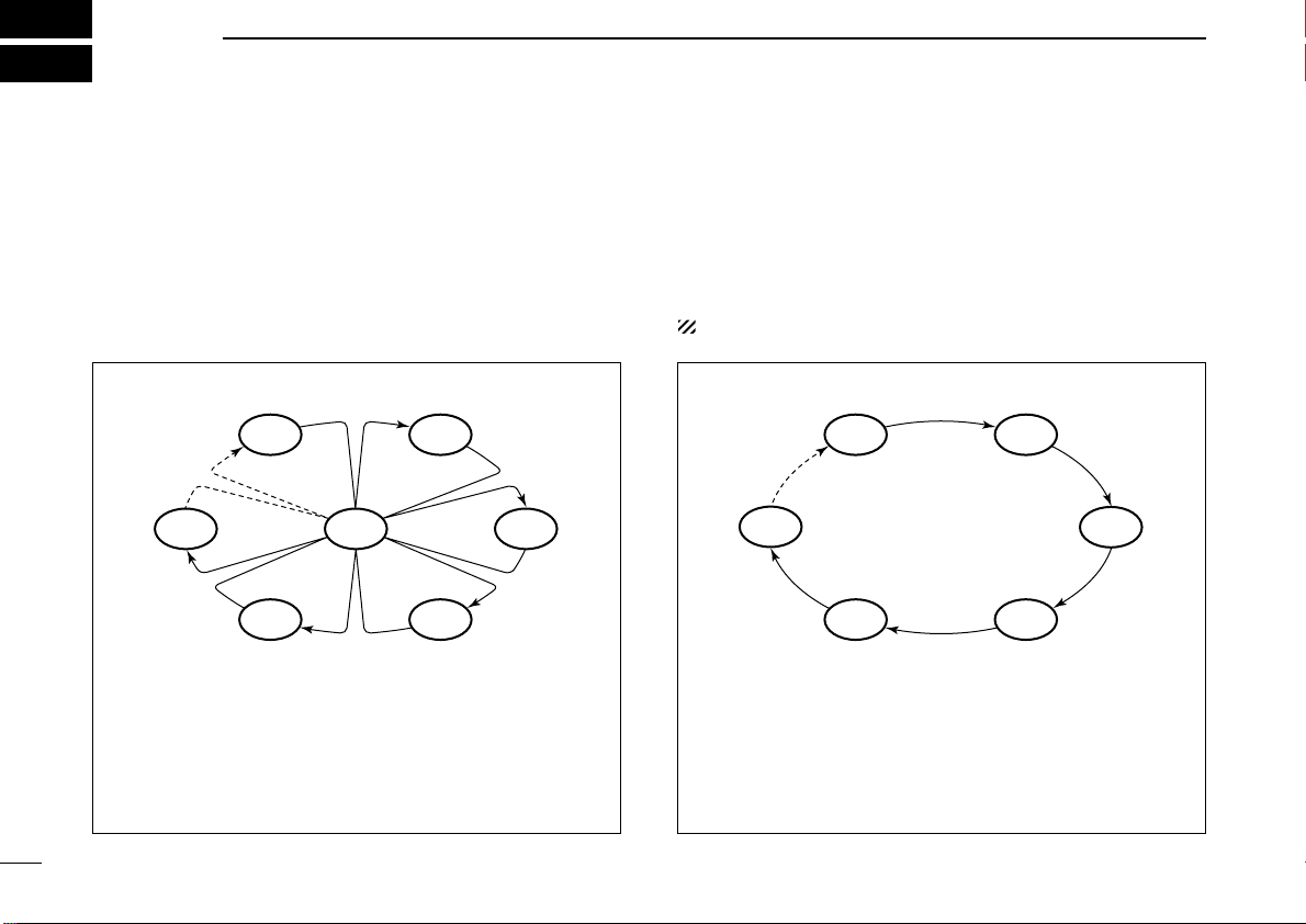
SCAN OPERATION
■ Scan types
Scanning is an efficient way to locate signals quickly over a
wide frequency range. The transceiver has priority scan and
normal scan.
PRIORITY SCAN
Priority scan searches through all tag channels in sequence while monitoring Channel 16. When a signal is detected on Channel 16, scan pauses until the signal disappears; when a signal is detected on a channel other than
Channel 16, scan becomes dualwatch until the signal disappears.
Set the tag channels (scanned channel) before scanning.
Clear the tag channels which inconveniently stop scanning,
such as those for digital communication use. (Refer to right
page for details.)
Choose priority or normal scan in set mode. (p. 45)
NORMAL SCAN
Normal scan, like priority scan, searches through all tag
channels in sequence. However, unlike priority scan, Channel 16 is not checked unless Channel 16 is set as a tag
channel.
12
Page 19
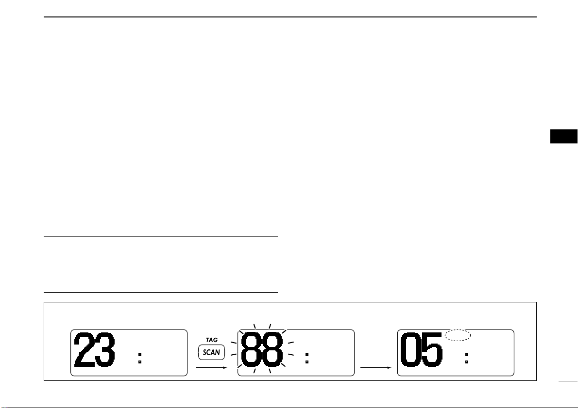
SCAN OPERATION
[Example]: Starting a normal scan.
-INTINT----
25W25W-DUPDUP-TAGTAG-
-
2323 34.154N34.154N-
135135 34.351E34.351E-
- INTLINTL - UTCUTC-12:0012:00-
-INTINT----
25W25W-DUPDUP-TAGTAG-
NORMALNORMAL SCANSCAN-
2323 34.154N34.154N-
135135 34.351E34.351E-
--UTCUTC-12:0012:00-
BUSYBUSY-INTINT----
25W25W-DUPDUP-TAGTAG-
NORMALNORMAL SCANSCAN-
2323 34.154N34.154N-
135135 34.351E34.351E-
- INTLINTL - UTCUTC-12:0012:00-
Push
Scan starts. When a signal is received.
5
■ Setting tag channels
For more efficient scanning, add the desired channels as tag
channels or clear the tag for unwanted channels.
Channels are not tagged will be skipped during scanning. Tag
channels can be assigned to each channel group (International and U.S.A.*) independently.
q Push both [▲] and [▼] to select the desired channel group
(International and U.S.A.*).
w Select the desired channel to be set as a tag channel.
e Push [SCAN•TAG] for 1 sec. to set the displayed channel
as a tag channel.
•“TAG” appears in the display.
r To cancel the tag channel setting, repeat step e.
•“TAG” disappears.
✔ Clearing (or setting) all tagged channels
While pushing [HI/LO] on the microphone, push [SCAN•TAG]
for 3 sec. (until a long beep changes to 2 short beeps) to clear
all tag channels in the channel group.
• Repeat above procedure to set all tag channels.
■ Starting a scan
Set scan type (priority or normal scan) and scan resume timer
in advance using set mode. (p. 45)
q Push [▲] and [▼] to select the desired channel group (In-
ternational and U.S.A.*) if desired.
w Set tag channels as described at left.
e Make sure the squelch is closed to start a scan.
r
Push [SCAN•TAG] to start priority or normal scan.
•“PRI-SCAN 16” or “NORMAL SCAN” appears in the function
display.
• When a signal is detected, scan pauses until the signal disappears or resumes after pausing 5 sec. according to set mode
setting. (Channel 16 is still monitored during priority scan.)
• Push [▲] or [▼] to check the scanning tag channels, to change
the scanning direction or resume the scan manually.
• A beep tone sounds and “16” blinks when a signal is received
on Channel 16 during priority scan.
t To stop the scan, push
*U.K. version only
[SCAN•TAG]
.
5
13
Page 20
6
--DSC Menu-MMSI Check
Input 9 digits
_________
<CLR˘Exit / ENT˘OK>
--DSC Menu-Set up
DEL:INDV ID ≤
DEL:Group ID
Offset Time
˘MMSI Check ≥
--DSC Menu--
Select Item
Position Input
Received Calls
˘Set up
Exit
DSC OPERATION
■ MMSI code programming
14
The 9-digit MMSI (Maritime Mobile Service Identity: DSC self
ID) code can be programmed at power ON.
This code programming can be performed only once.
q Turn power OFF.
w While pushing [MENU], turn power ON to enter MMSI
code programming condition.
e After the display appears, release [MENU].
r Push [MENU] again to enter the DSC menu.
t Push [▲] or [▼] to select “Set up,” push [ENT].
y Push [▲] or [▼]
to select “MMSI Check,” push
[ENT]
.
u Push [▲] or [▼]
•
Push [CH•DUAL] or [16•C] to move the cursor forward or backward, respectively.
• Push [SCAN•TAG] to clear the MMSI code.
• Push [CLR] to cancel and exit the condition to the set up menu.
i After input the 9-digit code, push [ENT] to set the code.
• Returns to the set up menu.
o Push [CLR] or [▼] to select “Exit,” push [ENT].
• Returns to the DSC menu.
• Repeat again to return to the normal operation condition.
to set
the specific 9-digit MMSI code.
Page 21

■ MMSI code check
--DSC Menu--
MMSI Check
123456789
<CLR˘Exit>
--DSC Menu-Set up
DEL:INDV ID ≤
DEL:Group ID
Offset Time
˘MMSI Check ≥
--DSC Menu--
Select Item
Polling Request ≤
Received Calls
Distress Setting
˘Set up ≥
DSC OPERATION
6
The 9-digit MMSI (DSC self ID) code can be checked.
q Push [MENU] to enter the DSC menu.
w Push [▲] or [▼] to select “Set up,” and push
e Push [▲] or [▼]
r Check the 9-digit MMSI (DSC self ID) code.
to select “MMSI Check,” push [ENT].
[ENT]
t Push [CLR] or [▼] to select “Exit,” push [ENT].
• Returns to the DSC menu.
• Repeat again to return to the normal operation condition.
.
6
15
Page 22

6 DSC OPERATION
--DSC Menu--
Add:Individual ID
Input name
__________
<CLR˘Exit / ENT˘OK>
--DSC Menu-Add:Individual ID
Input 9 digits
_________
<CLR˘Exit / ENT˘OK>
--DSC Menu--
Set up
˘Add:INDV ID
Add:Group ID
DEL:INDV ID
DEL:Group ID ≥
--DSC Menu--
Select Item
Polling Request ≤
Received Calls
Distress Setting
˘Set up ≥
■ DSC individual ID
16
A total of 100 DSC address IDs can be programmed and
named with up to 10 characters.
DD
Programming Address ID
q Push [MENU] to enter the DSC menu.
w Push [▲] or [▼] to select “Set up,” and push [ENT].
e Push [▲] or [▼]
r Push [▲] or [▼]
• Push [CH•DUAL] or [16•C] to move the cursor forward or back-
ward, respectively.
• Push [SCAN•TAG ] to clear the ID.
• Push [CLR] to cancel and exit the condition to the set up menu.
• “Full ID” appears when 100 DSC address IDs are already
set.
to select “Add:INDV ID,” push
to s
et the individual ID.
[ENT]
1st digit ‘0’ is fixed for a group ID. When you input 1st digit ‘0’
and other 8 digits, the ID is automatically registered as a group
ID.
t After input the 9-digit code, push [ENT] to set up to a 10-
character ID name using [▲] or [▼].
• Push [CH•DUAL] or [16•C] to move the cursor forward or back-
ward, respectively.
.
• Push [SCAN•TAG] to clear the ID name.
• Push [CLR] to cancel and exit the condition to the set up menu.
y Push [ENT] to program.
u Push [CLR] or [▼] to select “Exit,” push [ENT].
• Returns to the DSC menu.
• Repeat again to return to the normal operation condition.
Page 23

DD
--DSC Menu-Select ID
Bob
John
˘Cindy ≥
<CLR˘Exit / ENT˘OK>
--DSC Menu-Set up
Add:INDV ID
Add:Group ID
˘DEL:INDV ID
DEL:Group ID ≥
--DSC Menu--
Select Item
Polling Request ≤
Received Calls
Distress Setting
˘Set up ≥
Deleting address ID
q Push [MENU] to enter the DSC menu.
w Push [▲] or [▼] to select “Set up,” and push [ENT].
DSC OPERATION
r Push [▲] or [▼] to select the desired ID name for delet-
ing.
6
6
e Push [▲] or [▼]
• When no address ID is programmed, “
Push [CLR] to exit the condition.
to select “DEL:INDV ID,” push
No ID
[ENT]
” is displayed.
t Push [ENT] to delete the address ID and returns to the set
.
up menu.
y Push [CLR] or [▼] to select “Exit,” push [ENT].
• Returns to the DSC menu.
• Repeat again to return to the normal operation condition.
17
Page 24

6 DSC OPERATION
--DSC Menu-Add:Group ID
Input name
__________
<CLR˘Exit / ENT˘OK>
--DSC Menu-Add:Group ID
Input 8 digits
0________
<CLR˘Exit / ENT˘OK>
--DSC Menu-Set up
Add:INDV ID
˘Add:Group ID
DEL:INDV ID
DEL:Group ID ≥
--DSC Menu--
Select Item
Polling Request ≤
Received Calls
Distress Setting
˘Set up ≥
DD
Programming Group ID
q Push [MENU] to enter the DSC menu.
w Push [▲] or [▼] to select “Set up,” and push [ENT].
e Push [▲] or [▼]
[ENT]
.
to select “Add:Group ID,” push
t After input the 8-digit code, push [ENT] to input up to a 10-
character ID name using [▲] or [▼].
• Push [CH•DUAL] or [16•C] to move the cursor forward or back-
ward, respectively.
• Push [SCAN•TAG] to clear the ID name.
• Push [CLR] to cancel and exit the condition to the set up menu.
18
r Push [▲] or [▼]
• 1st digit ‘0’ is fixed for a group ID.
• Push [CH•DUAL] or [16•C] to move the cursor forward or back-
ward, respectively.
• Push [SCAN•TAG ] to clear the ID.
• Push [CLR] to cancel and exit the condition to the set up menu.
• “Full ID” appears when 100 DSC address IDs are already
set.
to s
et the Group ID.
y Push [ENT] to program.
u Push [CLR] or [▼] to select “Exit,” push [ENT].
• Returns to the DSC menu.
• Repeat again to return to the normal operation condition.
Page 25

DD
--DSC Menu-Select ID
Office
Icom
˘Station A ≥
<CLR˘Exit / ENT˘OK>
--DSC-Menu-Set up
Add:INDV ID
Add:Group ID
DEL:INDV ID
˘DEL:Group ID ≥
--DSC Menu--
Select Item
Polling Request ≤
Received Calls
Distress Setting
˘Set up ≥
Deleting group ID
q Push [MENU] to enter the DSC menu.
w Push [▲] or [▼] to select “Set up,” and push [ENT].
DSC OPERATION
r Push [▲] or [▼] to select the desired ID name for delet-
ing.
6
6
e Push [▲] or [▼]
[ENT]
.
• When no group ID is programmed, “
[CLR] to exit the condition.
to select “DEL:Group ID,” push
No ID
” is displayed. Push
t Push [ENT] to delete the group ID and returns to the set
up menu.
y Push [CLR] or [▼] to select “Exit,” push [ENT].
• Returns to the DSC menu.
• Repeat again to return to the normal operation condition.
19
Page 26

6 DSC OPERATION
--DSC Menu-Input Position
Longitude
___ __.___W Null
<SCAN˘Null Data>
<CLR˘Exit / ENT˘OK>
--DSC Menu-Input Position
Latitude
__ __.___N Null
<SCAN˘Null Data>
<CLR˘Exit / ENT˘OK>
--DSC Menu-Select Item
˘Position Input
Individual Call
Group Call
All Ships Call ≥
■
Position and time programming
20
A distress call should include the ship’s position and time
data. If no GPS is connected, your position and UTC (Universal Time Coordinated) time should be input manually. They
are included automatically when a GPS receiver (NMEA0183
ver. 2.0 or 3.01) is connected.
q Push [MENU] to enter the DSC menu.
w Push [▲] or [▼ ] to select “Position Input,” and
push [ENT].
e The position information appears. Set your latitude data
using [▲] or [▼]. After setting the latitude data, push [ENT]
to set your
• Push [CH•DUAL] or [16•C] to move the cursor forward or back-
ward, respectively.
• Push [▲ ] or [▼] to edit N; North latitude or S; South latitude
when the cursor is on the ‘N’ or ‘S’ position, and W; West longitude or E; East longitude when the cursor is on the ‘W’ or ‘E’ position.
• Push [SCAN•TAG] to clear the latitude/
• Push [CLR] to cancel and exit the condition to the DSC menu.
longitude data
Set the latitude data
Set the longitude data
.
longitude
data.
Page 27

DSC OPERATION
INT
25W TAG
23 34.154N
135 34.351E
CALLING UTC 12:00
--DSC Menu--
Input UTC Time
__:__ Null
<SCAN˘Null Data>
<CLR˘Exit / ENT˘OK>
■ Position and Time indication
6
r After setting the longitude data, push [ENT] to set the time
information appears. Set the current UTC time with [▲] or
[▼], then push [ENT].
• Push [CH•DUAL] or [16•C] to move the cursor forward or back-
ward, respectively.
• Push [SCAN•TAG ] to clear the UTC time data.
• Push [CLR] to cancel and exit the condition to the DSC menu.
t Push [CLR] or [▼] to select “Exit,” push [ENT].
• Returns to the DSC menu.
• Repeat again to return to the normal operation condition.
Manually programmed position data will be held for 23.5
hours only.
“??” may blink instead of position and time indications
when the GPS data is invalid, or has not been manually
updated after 4 hours.
When a GPS receiver (NMEA0183 ver. 2.0 or 3.01) is connected, the transceiver displays the current position and time.
When no GPS receiver is connected, the transceiver displays
the manually entered position and time.
A GPS receiver appropriate for the IC-M421 is not supplied
from Icom. A GPS receiver with NMEA0183 ver. 2.0 or 3.01
format is required for position indication. Ask your dealer
about suitable GPS receivers.
When connecting GPS receiver is compatible with several
sentence formatters, the order of input precedence is
‘RMC,’ ‘GGA,’ ‘GNS’ and ‘GLL.’
6
21
Page 28

6 DSC OPERATION
INT
25W TAG
RCV DTRS ACK
<Osaka Bay
<CLR˘
CALLING Beep Off>
Distress Call
TX Completed
Now Waiting for ACK
<CLR˘Cancel>
INT
25W TAG
Wait ACK
<CLR˘
CALLING Cancel>
After 2 sec.
Distress Call
Push for 5 sec.
■ Distress call
22
A distress call should be transmitted, if in the opinion of the
Master, the ship or a person is in distress and requires immediate assistance.
NEVER USE THE DISTRESS CALL WHEN YOUR
SHIP OR A PERSON IS NOT IN AN EMERGENCY.
A DISTRESS CALL CAN BE USED ONLY WHEN
IMMEDIATE HELP IS NEEDED.
DD
Simple call
q Confirm no distress call is being received.
w While lifting up the key cover, push [DISTRESS] for
5 sec. to transmit the distress call.
• Emergency channel (Ch 70) is automatically selected and the
distress call is transmitted.
• When no GPS is connected, input your position and UTC time, if
possible.
• While pushing [DISTRESS], the key backlighting is blinking.
e After transmitting the distress call, the transceiver waits for
an acknowledgment call on Ch 70.
• The distress call is automatically transmitted every 3.5 to 4.5
minutes.
• After 2 sec., the transceiver is set to Channel 16 automatically.
r After receiving the acknowledgment, reply using the mi-
crophone.
Page 29

DSC OPERATION
--DSC Menu--
Select Nature
Undesignated
˘Explosion
Flooding ≥
<CLR˘Exit / ENT˘OK>
--DSC Menu-Select Item
˘Position Report ≤
Polling Request
Received Calls
˘Distress Setting ≥
6
➥ A distress alert contains (default);
• Nature of distress: Undesignated distress
• Position data : GPS or manual input position data held for
23.5 hrs or until the power is turned OFF.
➥ The distress call is repeated every 3.5–4.5 min., until re-
ceiving an ‘acknowledgement.’
➥ Push [CLR] to cancel the ‘Call repeat’ mode.
➥ “??” may blink instead of position and time indications
when the GPS data is invalid, or has not been manually
updated after 4 hours.
DD
Normal call
The nature of the distress call should be included in the distress call.
q Push [MENU] to enter the DSC menu.
w Push [▲] or [▼] to select “Distress Setting,” and
push [ENT].
e Push [▲] or [▼] to select the nature of the distress, push
[ENT].
• ‘Undesignated,’ ‘Explosion,’ ‘Flooding,’ ‘Collision,’ ‘Grounding,’
‘Capsizing,’ ‘Sinking,’ ‘Adrift (Disable adrift),’ ‘Abandoning (Abandoning ship),’ ‘Piracy (Piracy attack),’ and ‘MOB (Man overboard)’ are available.
• The selected nature of the distress is stored for 10 minutes.
6
23
Page 30

6 DSC OPERATION
Distress Call
TX Completed
Now Waiting for ACK
<CLR˘Cancel>
INT
25W TAG
Wait ACK
<CLR˘
CALLING Cancel>
After 2 sec.
--DSC Menu--
Input UTC Time
__:__ Null
<SCAN˘Null Data>
<CLR˘Exit / ENT˘OK>
--DSC Menu-Input Position
Longitude
___ __.___W Null
<SCAN˘Null Data>
<CLR˘Exit / ENT˘OK>
--DSC Menu-Input Position
Latitude
__ __.___N Null
<SCAN˘Null Data>
<CLR˘Exit / ENT˘OK>
24
When a GPS receiver (NMEA0183 ver. 2.0 or 3.01) is connected,
ming) do not appear. Go to step y.
r The position information appears. Set your latitude data
using [▲] or [▼]. After setting the latitude data, push [ENT]
to set your
• Push [CH•DUAL] or [16•C] to move the cursor forward or back-
• Push [▲ ] or [▼] to edit N; North latitude or S; South latitude
• Push [SCAN•TAG ] to clear the latitude/
• Push [CLR] to cancel and exit the condition to the DSC menu.
next steps r, t (
longitude data
ward, respectively.
when the cursor is on the ‘N’ or ‘S’ position, and W; West longitude or E; East longitude when the cursor is on the ‘W’ or ‘E’ position.
Set the latitude data
Current position/time program-
.
longitude
data.
Set the longitude data
t After setting the
rent UTC time using [▲] or [▼], then push [ENT].
• Push [CH•DUAL] or [16•C] to move the cursor forward or back-
ward, respectively.
• Push [SCAN•TAG] to clear the UTC time data.
• Push [CLR] to cancel and exit the condition to the DSC menu.
y Push [DISTRESS] for 5 sec. to transmit the distress call.
• While pushing [DISTRESS], the key backlighting is blinking.
u After transmitting the distress call, the transceiver waits for
an acknowledgment call on Ch 70.
• The distress call is automatically transmitted every 3.5 to 4.5 min.
• After 2 sec., the transceiver is set to Channel 16 automatically.
longitude
data, push [ENT] to set the cur-
Page 31

DSC OPERATION
--DSC Menu-Select Address
˘Manual Input
Bob
˘John ≥
<CLR˘Exit / ENT˘OK>
--DSC Menu-Select Item
˘Position Input
˘Individual Call
Group Call
All Ships Call ≥
INT
25W TAG
RCV DTRS ACK
<Osaka Bay
<CLR˘
CALLING Beep Off>
6
i After receiving the acknowledgment, reply using the mi-
crophone.
➥ A distress alert contains (default);
• Nature of distress: Selected nature of the distress
• Position data : GPS or manual input position data held for
23.5 hrs or until the power is turned OFF.
➥ The distress call is repeated every 3.5–4.5 min., until re-
ceiving an ‘acknowledgement.’
➥ Push [CLR] to cancel the ‘Call repeat’ mode.
➥ “??” may blink instead of position and time indications
when the GPS data is invalid, or has not been manually
updated after 4 hours.
■ Transmitting DSC calls
To ensure correct operation of the DSC function, please
make sure you set the squelch correctly. (p. 8)
DD
Transmitting an individual call
The individual call function allows you to transmit a DSC signal to a specific ship only.
q Push [MENU] to enter the DSC menu.
w Push [▲] or [▼] to select “Individual Call,” and
push [ENT].
e Push [▲] or [▼] to select the desired pre-programmed in-
dividual address or “Manual Input,” push [ENT].
• The ID code for the individual call can be set in advance. (p. 16)
• When “Manual Input” is selected, set the 9-digit ID code
for the individual you wish to call with [▲] or [▼].
1st digit ‘0’ is fixed for a group ID.
6
25
Page 32

6 DSC OPERATION
-INT----
25W--TAG-
RCV INDV ACK
<John -
<CLR˘ -
COMMERCI Beep Off> -
‘Able to comply’ is received.
-INT----
25W--TAG-
RCV Unable
<John -
<CLR˘ -
INTL Beep Off> -
‘Unable to comply’ is received.
--DSC Menu--
Individual Call
TX Completed
Now Waiting for ACK
<CLR˘Exit>
Transmitting
--DSC Menu--
Individual Call
--DSC Menu-Select Intership CH
˘08
69
77 ≥
<CLR˘Exit / ENT˘OK>
--DSC Menu--
Individual Call Ready
<CLR˘Exit / ENT˘OK>
Push
26
r Push [▲] or [▼] to select a desired intership channel or
“Manual Input,” push [ENT].
• Intership channels are already preset into the transceiver in recommending order.
t Push [ENT] to transmit the individual call.
• If Channel 70 is busy, the transceiver stands by until the channel
becomes clear.
y Standby on Channel 70 until an acknowledgement is re-
ceived.
u When the acknowledgement ‘Able to comply’ is received,
the specified channel (in step r) is selected with beeps
automatically. Or, when the acknowledgement ‘Unable to
comply’ is received, the display returns to the operated
channel (before enter the DSC menu) with beeps.
i Push [CLR] to stop the beep, then push and hold [PTT] to
communicate your message to the responding ship.
Page 33

DD
--DSC Menu--
Select Action
˘Able to Comply
Unable to Comply
<CLR˘Exit / ENT˘OK>
--DSC Menu--
Individual Call Ready
<CLR˘Exit / ENT˘OK>
Push
--DSC Menu-Select Address
˘John 01
Beck 02
Bob 03≥
<CLR˘Exit / ENT˘OK>
--DSC Menu-Select Item
Position Input
Individual Call
˘Individual ACK
Group Call ≥
Transmitting an individual acknowledgement
When receiving an individual call, you can transmit an acknowledgement (‘Able to comply’ or ‘Unable to comply’) by
using the on screen prompts (see page 38 for details). Alternatively, you can send an acknowledgement through the
menu system as follows.
q Push [MENU] to enter the DSC menu.
w Push [▲] or [▼ ] to select “Individual ACK,” and
push [ENT].
•“Individual ACK” item appears after an individual call is
received.
DSC OPERATION
r Push [▲] or [▼] to select that you can comply to the call or
not from “Able to Comply” or “Unable to Com-
ply,” then push [ENT].
• When “Unable to Comply” is selected, the reason “No
Reason Given” will be transmitted.
6
6
e Push [▲] or [▼] to select the desired individual address or
ID code, push [ENT].
t Push [ENT] to transmit the acknowledgement call to the
selected station.
y After the individual acknowledgement call has been trans-
mitted, the specified channel (specified by the calling station) is selected automatically when “Able to Com-
ply” is selected, or returns to the previous condition
(before entering the DSC menu) when “Unable to
Comply” is selected in step r.
27
Page 34

6 DSC OPERATION
--DSC Menu--
Group Call
TX Completed
<CLR˘Exit>
--DSC Menu-Select Intership CH
˘08
69
77 ≥
<CLR˘Exit / ENT˘OK>
--DSC Menu--
Group Call Ready
<CLR˘Exit / ENT˘OK>
Push
--DSC Menu-Select Address
Manual Input
˘Office
Icom ≥
<CLR˘Exit / ENT˘OK>
--DSC Menu-Select Item
˘Position Input
Individual Call
˘Group Call
All Ships Call ≥
DD
Transmitting a group call
The group call function allows you to transmit a DSC signal to
a specific group only.
q Push [MENU] to enter the DSC menu.
w Push [▲] or [▼] to select “Group Call,” and push
[ENT].
28
e Push [▲] or [▼] to select the desired pre-programmed
group address or “Manual Input,” push [ENT].
• The ID code for the group call can be set in advance. (p. 18)
• When “Manual Input” is selected, set the 8-digit ID code
for the group you wish to call with [▲] or [▼].
r Push [▲] or [▼] to select a desired intership channel or
“Manual Input,” push [ENT].
•Intership channels are already preset into the transceiver in recommending order.
t Push [ENT] to transmit the group call.
• If Channel 70 is busy, the transceiver stands by until the channel
becomes clear.
y After the group call has been transmitted, the following in-
dication is displayed.
u Push [CLR] to exit the condition and selects the specified
intership channel in step r automatically.
• Even if [CLR] hasn’t been pushed, the transceiver selects the
specified intership channel in step r automatically after 2 sec. of
inactivity.
Page 35

DD
--DSC Menu--
All Ships Call
TX Completed
<CLR˘Exit>
--DSC Menu--
All Ships Call
Transmitting
--DSC Menu-Select Category
˘Safety
Urgency
<CLR˘Exit / ENT˘OK>
--DSC Menu--
All Ships Call Ready
<CLR˘Exit / ENT˘OK>
Push
--DSC Menu-Select Item
˘Position Input
Individual Call
Group Call
˘All Ships Call ≥
Transmitting an all ships call
Large ships use Channel 70 as their ‘listening channel.’ When
you want to announce a message to these ships, use the all
ships call function.
q Push [MENU] to enter the DSC menu.
w Push [▲] or [▼] to select “All Ships Call,” and
push [ENT].
e Push [▲] or [▼] to select the desired category, push
[ENT].
• The selectable category may differ according to the programmed
setting. Ask your dealer for the available categories.
DSC OPERATION
r Push [ENT] to transmit the all ships call.
• Channel 70 is selected and the all ships call is transmitted.
t After the all ships call has been transmitted, the following
indication is displayed.
6
6
y Push [CLR] to exit the condition and selects Channel 16
automatically.
• Even if [CLR] hasn’t been pushed, the transceiver automatically
selects Channel 16 after 2 sec. of inactivity.
29
Page 36

6 DSC OPERATION
--DSC Menu--
Position Request
TX Completed
Now Waiting for ACK
<CLR˘Exit>
Transmitting
--DSC Menu--
Position Request
--DSC Menu-Select Address
˘Manual Input
Bob
˘John ≥
<CLR˘Exit / ENT˘OK>
--DSC Menu--
POS Request Ready
<CLR˘Exit / ENT˘OK>
Push
--DSC Menu-Select Item
˘Individual Call ≤
Group Call
All Ships Call
˘Position Request ≥
DD
Transmitting a position request call
Transmit a position request call when you want to know a
specific ship’s current position, etc.
q Push [MENU] to enter the DSC menu.
w Push [▲] or [▼] to select “Position Request,” and
push [ENT].
e Push [▲] or [▼] to select the desired pre-programmed in-
dividual address or “Manual Input,” push [ENT].
• The ID code can be set in advance. (p. 16)
• When “Manual Input” is selected, set the 9-digit ID code
for the individual you wish to call with [▲] or [▼].
r Push [ENT] to transmit the position request call.
• If Channel 70 is busy, the transceiver stands by until the channel
becomes clear.
t After the position request call has been transmitted, the fol-
lowing indication is displayed.
30
y Push [CLR] to return to the previous indication before en-
tering the DSC menu.
• Even if [CLR] hasn’t been pushed, the display automatically returns to the previous indication after 2 sec. of inactivity.
Page 37

DD
--DSC Menu-Input Position
Longitude
___ __.___W Null
<SCAN˘Null Data>
<CLR˘Exit / ENT˘OK>
--DSC Menu-Input Position
Latitude
__ __.___N Null
<SCAN˘Null Data>
<CLR˘Exit / ENT˘OK>
--DSC Menu-Select Address
˘Manual Input
Bob
˘John ≥
<CLR˘Exit / ENT˘OK>
--DSC Menu-Select Item
˘Group Call ≤
All Ships Call
Position Request
˘Position Report- ≥
Transmitting a position report call
Transmit a position report call when you want to announce
your own position to a specific ship and to get an answer, etc.
q Push [MENU] to enter the DSC menu.
w Push [▲] or [▼] to select “Position Report,” and
push [ENT].
e Push [▲] or [▼] to select the desired pre-programmed in-
dividual address or “Manual Input,” push [ENT].
• The ID code can be set in advance. (p. 16)
• When “Manual Input” is selected, set the 9-digit ID code
for the individual you wish to call with [▲] or [▼].
DSC OPERATION
When a GPS receiver (NMEA0183 ver. 2.0 or 3.01) is connected,
ming) do not appear. Go to step y.
r The position information appears. Set your latitude data
using [▲] or [▼]. After setting the latitude data, push [ENT]
to set your
• Push [CH•DUAL] or [16•C] to move the cursor forward or back-
• Push [▲ ] or [▼] to edit N; North latitude or S; South latitude
• Push [SCAN•TAG] to clear the latitude/
• Push [CLR] to cancel and exit the condition to the DSC menu.
next steps r, t (
longitude data
ward, respectively.
when the cursor is on the ‘N’ or ‘S’ position, and W; West longitude or E; East longitude when the cursor is on the ‘W’ or ‘E’ position.
Set the latitude data
Current position/time program-
.
longitude
data.
6
6
Set the longitude data
31
Page 38

6 DSC OPERATION
--DSC Menu--
Position Report
TX Completed
Now Waiting for ACK
<CLR˘Exit>
--DSC Menu--
Position Report
Transmitting
--DSC Menu--
Input UTC TIme
__:__ Null
<SCAN˘Null Data>
<CLR˘Exit / ENT˘OK>
--DSC Menu--
POS Report Ready
<CLR˘Exit / ENT˘OK>
Push
32
t After setting the longitude data, push [ENT] to set the time
information appears. Set the current UTC time with [▲] or
[▼], then push [ENT].
• Push [CH•DUAL] or [16•C] to move the cursor forward or back-
ward, respectively.
• Push [SCAN•TAG] to clear the UTC time data.
• Push [CLR] to cancel and exit the condition to the DSC menu.
y Push [ENT] to transmit the position report call.
• If Channel 70 is busy, the transceiver stands by until the channel
becomes clear.
u After the position report call has been transmitted, the fol-
lowing indication is displayed.
i Push [CLR] to return to the previous indication before en-
tering the DSC menu.
• Even if [CLR] hasn’t been pushed, the display automatically returns to the previous indication after 2 sec. of inactivity.
Page 39

DD
--DSC Menu--
Polling Request
TX Completed
Now Waiting for ACK
<CLR˘Exit>
Transmitting
--DSC Menu--
Polling Request
--DSC Menu-Select Address
˘Manual Input
˘Bob
John ≥
<CLR˘Exit / ENT˘OK>
--DSC Menu--
POLL Request Ready
<CLR˘Exit / ENT˘OK>
Push
--DSC Menu-Select Item
˘All Ships Call ≤
Position Request
Position Report
˘Polling Request ≥
Transmitting a polling request call
Transmit a polling request call when you want to know a specific ship is in the communication area, etc.
q Push [MENU] to enter the DSC menu.
w Push [▲] or [▼] to select “Polling Request,” and
push [ENT].
e Push [▲] or [▼] to select the desired pre-programmed in-
dividual address or “Manual Input,” push [ENT].
• The ID code can be set in advance. (p. 16)
• When “Manual Input” is selected, set the 9-digit ID code
for the individual you wish to call with [▲] or [▼].
DSC OPERATION
r Push [ENT] to transmit the polling request call.
• If Channel 70 is busy, the transceiver stands by until the channel
becomes clear.
t After the polling request call has been transmitted, the fol-
lowing indication is displayed.
6
6
y Push [CLR] to return to the previous indication before en-
tering the DSC menu.
• Even if [CLR] hasn’t been pushed, the display automatically returns to the previous indication after 2 sec. of inactivity.
33
Page 40

6 DSC OPERATION
--DSC Menu-Input Position
Longitude
___ __.___W Null
<SCAN˘Null Data>
<CLR˘Exit / ENT˘OK>
--DSC Menu-Input Position
Latitude
__ __.___N Null
<SCAN˘Null Data>
<CLR˘Exit / ENT˘OK>
--DSC Menu-Select Address
˘Paul 01
Beck 02
John 03≥
<CLR˘Exit / ENT˘OK>
--DSC Menu-Select Item
Group Call
All ships Call
Position Request
˘Position Reply ≥
DD
Transmitting a position reply call
Transmit a position reply call when a position request call is
received.
q Push [MENU] to enter the DSC menu.
w Push [▲] or [▼ ] to select “Position Reply,” and
push [ENT].
•“Position Reply” item appears after a position request
call is received.
e Push [▲] or [▼] to select the desired individual address or
ID code, push [ENT].
When a GPS receiver (NMEA0183 ver. 2.0 or 3.01) is connected,
ming) do not appear. Go to step y.
r The position information appears. Set your latitude data
using [▲] or [▼]. After setting the latitude data, push [ENT]
to set your
• Push [CH•DUAL] or [16•C] to move the cursor forward or back-
• Push [▲ ] or [▼] to edit N; North latitude or S; South latitude
• Push [SCAN•TAG] to clear the latitude/
• Push [CLR] to cancel and exit the condition to the DSC menu.
next steps r, t (
longitude data
ward, respectively.
when the cursor is on the ‘N’ or ‘S’ position, and W; West longitude or E; East longitude when the cursor is on the ‘W’ or ‘E’ position.
Set the latitude data
Current position/time program-
.
longitude
data.
34
Set the longitude data
Page 41

t After setting the longitude data, push [ENT] to set the time
--DSC Menu-Select Address
˘Paul 01
Beck 02
John 03≥
--DSC Menu--
POS Reply Ready
<CLR˘Exit / ENT˘OK>
Push
--DSC Menu-Select Item
All ships Call
Position Request
Position Report
˘POS Report Reply ≥
--DSC Menu--
Input UTC TIme
__:__ Null
<SCAN˘Null Data>
<CLR˘Exit / ENT˘OK>
--DSC Menu--
POS Reply Ready
<CLR˘Exit / ENT˘OK>
Push
information appears. Set the current UTC time with [▲] or
[▼], then push [ENT].
• Push [CH•DUAL] or [16•C] to move the cursor forward or back-
ward, respectively.
• Push [SCAN•TAG ] to clear the UTC time data.
• Push [CLR] to cancel and exit the condition to the DSC menu.
DSC OPERATION
DD
Transmitting a position report reply call
Transmit a position report reply call when a position report call
is received.
q Push [MENU] to enter the DSC menu.
w Push [▲] or [▼] to select “POS Report Reply,” and
push [ENT].
•“POS Report Reply” item appears after a position report
call is received.
e Push [▲] or [▼] to select the desired individual address or
ID code, push [ENT].
6
6
y Push [ENT] to transmit the position reply call to the se-
lected station.
• Your position data is transmitted, when [ENT] is pushed.
r Push [ENT] to transmit the position report reply call to the
selected station.
35
Page 42

6 DSC OPERATION
--DSC Menu-Select Address
˘Paul 01
Beck 02
John 03≥
<CLR˘Exit / ENT˘OK>
--DSC Menu--
POLL Reply Ready
<CLR˘Exit / ENT˘OK>
Push
--DSC Menu-Select Item
Position Request
Position Report
Polling Request
˘Polling Reply ≥
DD
Transmitting a polling reply call
Transmit a polling reply call when a polling request call is received.
q Push [MENU] to enter the DSC menu.
w Push [▲] or [▼] to select “Polling Reply,” and push
[ENT].
•“Polling Reply” item appears after a polling request call
is received.
e Push [▲] or [▼] to select the desired individual address or
ID code, push [ENT].
r Push [ENT] to transmit the polling request call to the se-
lected station.
36
Page 43

■ Receiving DSC calls
INT
25W TAG
RCV DTRS REL
<Bob
<CLR˘
CALLING Beep Off>
INT
25W TAG
RCV DTRS ACK
<Beck
<CLR˘
CALLING Beep Off>
INT
25W TAG
RCV DISTRESS
<Paul
<CLR˘
CALLING Beep Off>
DSC OPERATION
6
DD
Receiving a distress call
While monitoring Channel 70 and a distress call is received:
➥ The emergency alarm sounds for 2 minutes.
• Push [CLR] to stop the alarm.
➥ “RCV DISTRESS” appears in the display, then Channel
16 is automatically selected.
➥ Continue monitoring Channel 16 as a coast station may re-
quire assistance.
DD
Receiving a distress acknowledgement
While monitoring Channel 70 and a distress acknowledgement to other ship is received:
➥ The emergency alarm sounds for 2 minutes.
• Push [CLR] to stop the alarm.
➥ “RCV DTRS ACK” appears in the display, then Channel
16 is automatically selected.
DD
Receiving a distress relay call
While monitoring Channel 70 and a distress relay acknowledgement is received:
➥ The emergency alarm sounds for 2 minutes.
• Push [CLR] to stop the alarm.
➥ “RCV DTRS REL” appears in the display, then Channel
16 is automatically selected.
6
37
Page 44

6 DSC OPERATION
INT
25W TAG
RCV ALL SHIP
<Tokyo Bay
<CLR˘
SAFETY Beep Off>
INT
25W TAG
RCV GROUP
<Icom
<CLR˘
SAFETY Beep Off>
INT
25W TAG
RCV INDV
<Paul
<CLR˘
SAFETY Beep Off>
DD
Receiving an individual call
While monitoring Channel 70 and an individual call is received:
➥ The emergency alarm or beeps sound depending on the
received category.
➥ “RCV INDV” appears in the display.
➥ Push [CLR] to stop the beep, then push [ENT] to reply the
call and select the channel specified by the calling station
for voice communication (depending on your replying condition see p. 27 for individual acknowledgement call procedure for details.); push [CLR] to ignore the individual call.
DD
Receiving a group call
While monitoring Channel 70 and a group call is received:
➥ The emergency alarm or beeps sound depending on the
received category.
➥ “RCV GROUP” appears in the display.
➥ Push [CLR] to stop the beep, then push [ENT] to select
the channel specified by the calling station for voice communication; push [CLR] to ignore the group call.
DD
Receiving an all ships call
While monitoring Channel 70 and an all ships call is received:
➥ The emergency alarm sounds when the category is ‘Dis-
tress’ or ‘Urgency’; beeps sound for 2 minutes.
➥ “RCV ALL SHIP” appears in the display.
➥ Push [CLR] to stop the beep, then push [ENT] to monitor
channel 16 for an announcement from the calling vessel,
push [CLR] to ignore the call.
38
Page 45

DSC OPERATION
INT
25W TAG
RCV POS RPT
<Paul
<CLR˘
SAFETY Beep Off>
INT
25W TAG
RCV POS REQ
<Paul
<CLR˘
SAFETY Beep Off>
INT
25W TAG
RCV GEOGRAPH
<Osaka Bay
<CLR˘
SAFETY Beep Off>
6
DD
Receiving a geographical area call
While monitoring Channel 70 and a geographical area call
(for the area you are in) is received:
➥ Emergency alarm or beeps sound depending on the re-
ceived category.
➥ “RCV GEOGRAPH” appears in the display.
➥ Push [CLR] to stop the beep, then push [ENT] to change
to the channel specified by the calling station for voice
communication; push other key to ignore the Geographical Area call.
➥ Monitor the selected channel for an announcement from
the calling station.
When no GPS receiver is connected or if there is a problem with the connected receiver, all geographical area calls
are received, regardless of your position.
DD
Receiving a position request call
While monitoring Channel 70 and a position request call is received:
➥ “RCV POS REQ” appears in the display.
➥ Push [CLR] to stop the beep, then push [ENT] to reply to
the position request call; push [CLR] to ignore the position
request call.
DD
Receiving a position report call
While monitoring Channel 70 and a position report call is received:
➥ “RCV POS RPT” appears in the display.
➥ Push [CLR] to stop the beep, then push [ENT] to reply to
the position report call; push [CLR] to ignore the position
report call.
6
39
Page 46

6 DSC OPERATION
INT
25W TAG
RCV POS RPY
<Paul
<CLR˘
SAFETY Beep Off>
INT
25W TAG
RCV POS RPY
<Paul
<CLR˘
SAFETY Beep Off>
INT
25W TAG
RCV POLL REQ
<Paul
<CLR˘
SAFETY Beep Off>
DD
Receiving a polling request call
While monitoring Channel 70 and a polling request call is received:
➥ “RCV POLL REQ” appears in the display.
➥ Push [CLR] to stop the beep, then push [ENT] to reply to
the call; push [CLR] to ignore the call.
DD
Receiving a position reply call
While monitoring Channel 70 and a position reply call is received:
➥ “RCV POS RPY” appears in the display.
➥ Push [CLR] to stop the beep, then push [ENT] to display
the position information; push [CLR] to ignore the reply
call.
DD
Receiving a position report reply call
While monitoring Channel 70 and a position report reply call
is received:
➥ “RCV POS RPY” appears in the display.
➥ Push [CLR] to stop the beep, then push [ENT] to display
the position information; push [CLR] to ignore the reply
call.
40
Page 47

■ Received messages
--DSC Menu-Distress
<Beck
Explosion
LAT: 12 34.567N
LON:123 45.678W
UTC:12:15
<CLR˘Exit / SCAN˘Del>
--DSC Menu--
Select Message
˘12:15 Beck 01
09:10 John 02
<CLR˘Exit / ENT˘OK>
--DSC Menu--
Select Message
˘Distress
Other
<CLR˘Exit / ENT˘OK>
--DSC Menu-Select Item
˘Position Request ≤
Position Report
Polling Request
˘Received Calls ≥
DSC OPERATION
6
The transceiver automatically stores up to 20 distress messages and 20 other messages. The messages can be used
as an assistance to the logbook.
q Push [MENU] to enter the DSC menu.
w Push [▲] or [▼ ] to select “Received Calls,” and
push [ENT].
DD
Distress message
q Push [▲] or [▼] to select “Distress,” push [ENT].
w Push [▲] or [▼] to scroll to the desired message, push
[ENT].
• Messages which are blinking have not read.
6
e Push [▲] or [▼] to scroll the message.
r Push [CLR] to exit the condition or push [SCAN] to delete
the displayed message and returns to DSC menu.
41
Page 48

6 DSC OPERATION
--DSC Menu-Individual Call
<Bob
Routine
F3E simplex
CH08
<CLR˘Exit / SCAN˘Del>
--DSC Menu--
Select Message
All Ships Call 01
Group Call 02
˘Individual Call 03≥
<CLR˘Exit / ENT˘OK>
--DSC Menu-Select Message
Distress
˘Other
<CLR˘Exit / ENT˘OK>
DD
Other messages
q Push [▲] or [▼] to select “Other,” push [ENT].
w Push [▲] or [▼] to scroll to the desired message, push
[ENT].
• Messages which are blinking have not read.
e Push [▲] or [▼] to scroll the message.
• The stored message has various information and depending on
the type of distress call.
r Push [CLR] to exit the condition or push [SCAN] to delete
the displayed message and returns to DSC menu.
42
Page 49

■ DSC Set mode
--DSC Menu--
Input Offset TIme
__0:00
<CLR˘Exit / ENT˘OK>
--DSC Menu--
Input Offset TIme
-12:00
<CLR˘Exit / ENT˘OK>
No offset time (default)
12 hours
--DSC-Menu-Set up
Add:Group ID ≤
DEL:INDV ID
DEL:Group ID
˘Offset Time ≥
--DSC Menu--
Select Item
Polling Request ≤
Received Calls
Distress Setting
˘Set up ≥
DSC OPERATION
6
DD
MMSI code check (See p. 15 for detail)
DD
Add Address ID (See p. 16 for detail)
DD
Delete Address ID (See p. 17 for detail)
DD
Offset time
This item sets the offset time from the UTC (Universal Time
Coordinated) time.
q Push [MENU] to enter the DSC menu.
w Push [▲] or [▼] to select “Set up,” and push [ENT].
e Push [▲] or [▼]
to select “Offset Time,” push
[ENT]
r Set the offset time from the UTC (Universal Time Coordi-
nated) time using [▲] or [▼].
• Push [CH•DUAL] or [16•C] to move the cursor forward or back-
ward, respectively.
• Push [SCAN•TAG] to clear the offset time data.
• Push [CLR] to cancel and exit the condition to the set up menu.
6
.
t Push [ENT] to program and to exit the condition to the set
up menu.
The local time indication is not available when the GPS receiver (sentence formatter RMC) is connected, the transceiver’s display indicates UTC time only.
43
Page 50

6 DSC OPERATION
--DSC Menu-Auto ACK
˘ON
OFF
<CLR˘Exit / ENT˘OK>
--DSC Menu--
Set up
DEL:Group ID ≤
Offset Time
MMSI Check
˘Auto ACK ≥
--DSC Menu-Select Item
Polling Request ≤
Received Calls
Distress Setting
˘Set up ≥
DD
Automatic acknowledgement
This item sets the automatic acknowledgement function ON
or OFF.
When a position request, position report or polling request call
is received, transceiver automatically transmits a position request reply, position report reply or polling reply call, respectively.
q Push [MENU] to enter the DSC menu.
w Push [▲] or [▼] to select “Set up,” and push [ENT].
r Push [▲] or [▼]
function ON or OFF
t Push [ENT] to set the condition.
• Push [CLR] to cancel and exit the condition to the set up menu.
to turn the
.
automatic acknowledgement
44
e Push [▲] or [▼]
to select “Auto ACK,” push
[ENT]
.
Page 51

SET MODE
Beep tone
BeepBeep
Scan type
Scan TypeScan Type
Scan resume timer
Scan TimerScan Timer
Dual/tri watch
Dual/TriDual/Tri
Backlight
BacklightBacklight
LCD contrast
ContrastContrast
:Push
:Push
• SET MODE CONSTRUCTION
--Set Mode--
˘Scan Type
Scan Timer
Dual/Tri
Beep
Backlight
Contrast
Exit
--Set Mode-Scan Timer
ON
˘OFF
<ENT˘OK>
Scan timer OFF (default)
--Set Mode-Scan Type
˘Priority
Normal
<ENT˘OK>
Priority scan (default)
7
■ Set mode programming
Set mode is used to change the conditions of the transceiver’s functions: scan type (normal or priority), scan resume
timer, dual/tri-watch, transceiver’s beep tone, backlight and
LCD contrast.
Available functions may differ depending on dealer setting.
q Turn power OFF.
w While pushing [16•C], turn power ON to enter set mode.
e After the display appears, release [16•C].
r Push [▲] or [▼] to select the desired item, push [ENT].
t Push [▲] or [▼] to select the desired condition of the item,
y Push [▼] to select “Exit,” then push [ENT] or push [CLR]
push [ENT].
to exit set mode and returns to normal operation condition.
■ Set mode items
DD
Scan type
The transceiver has 2 scan types: normal scan and priority
scan. Normal scan searches all tag channels in the selected
channel group. Priority scan searches all tag channels in sequence while monitoring Channel 16.
DD
Scan resume timer
The scan resume timer can be selected as a pause (OFF) or
timer scan (ON). When OFF is selected, the scan pauses
until the signal disappears. When ON is selected, the scan
pauses 5 sec. and resumes even if a signal has been received on any other channel than Channel 16.
6
7
45
Page 52

7 SET MODE
--Set Mode-Contrast
6 ≤
5
˘4 ≥
<ENT˘OK>
LCD contrast level 4 (default)
--Set Mode-Backlight
˘Max
Mid
Min ≥
<ENT˘OK>
LCD backlight level MAX (default)
--Set Mode--
Beep
˘ON
OFF
<ENT˘OK>
Beep tone ON (default)
--Set Mode-Dual/Tri
Tri-watch
˘Dualwatch
<ENT˘OK>
Dualwatch (default)
46
DD
Dual/Tri-watch
Select the watch function from Dualwatch or tri-watch. (p. 11)
DD
Beep tone
You can select the silent operation by turning beep tones
OFF, or you can have confirmation beeps sound at the push
of a key by turning beep tones ON.
DD
Backlight
The LCD backlight level can be adjusted from OFF, Min
(dark), Mid and Max (bright).
DD
LCD contrast
This item adjusts the contrast of the LCD in 8 steps. 1 is the
lowest contrast, and 8 is the highest contrast.
Page 53

CONNECTIONS AND MAINTENANCE
Fuse rating: 10 A
q
er o
tu
i
y
w
8
■ Supplied accessories
The following accessories are supplied:
q Mounting bracket ………………………………………… 1
w DC power cable (OPC-891) ……………………………… 1
e Microphone hanger ……………………………………… 1
r Knob bolts for mounting bracket ………………………… 2
t Screws for mounting bracket (5 × 20) ………………… 2
y Mic hanger screws (3 × 16) ……………………………… 2
u Flat washers for mounting bracket (M5) ……………… 2
i Spring washers for mounting bracket (M5) …………… 2
o RCA connector cable (OPC-1278) ……………………… 1
Qty.
■ Antenna
A key element in the performance of any communication system is an antenna. Ask your dealer about antenna and the
best place to mount them.
■ Fuse replacement
One fuse is installed in the supplied DC power cable. If a fuse
blows or the transceiver stops functioning, track down the
source of the problem, if possible, and replace the damaged
fuse with a new, rated one.
■ Cleaning
If the transceiver becomes dusty or dirty, wipe it clean with a
soft, dry cloth.
AVOID the use of solvents such as benzene or alcohol, as they may damage transceiver surfaces.
7
8
47
Page 54

8 CONNECTIONS AND MAINTENANCE
Rubber vulcanizing tape
NMEA (+)
RCA
NMEA (–)
e
q
w
r
■ Connections
q DC POWER CONNECTOR
Connects the supplied DC power cable from this connector
to an external 12 V battery.
w EXTERNAL SPEAKER JACK
Connects to an external speaker.
r ANTENNA CONNECTOR
Connects a marine VHF antenna with a PL-259 connector
to the transceiver.
CAUTION: Transmitting without an antenna may damage the transceiver.
CAUTION: After connecting the DC power cable, GPS receiver jack and external speaker jack, cover the connector
and jacks with an adhesive tape as shown below, to prevent water seeping into the transceiver.
48
e GPS RECEIVER JACK
Connects to a GPS receiver for position indication.
• A NMEA0183 ver. 2.0 or 3.01 (sentence formatters RMC, GGA,
GNS, GLL) compatible GPS receiver is required. Ask your dealer
about suitable GPS receivers.
Page 55

Flat washer
Spring
washer
Screw
(5 × 20 mm)
EXAMPLE
■ Mounting the transceiver
DD
Using the supplied mounting bracket
The universal mounting bracket supplied with your transceiver
allows overhead or dashboard mounting.
• Mount the transceiver securely with the 2 supplied screws
(5 × 20) to a surface which is more than 10 mm thick and
can support more than 5 kg.
• Mount the transceiver so that the face of the transceiver is at
90° to your line of sight when operating it.
CAUTION: KEEP the transceiver and microphone at least
1 meter away from your vessel’s magnetic navigation compass.
NOTE: Check the installation angle; the function display
may not be easy-to-read at some angles.
CONNECTIONS AND MAINTENANCE
8
8
49
Page 56

8 CONNECTIONS AND MAINTENANCE
■ Optional MB-69 installation
An optional MB-69
transceiver to a flat surface such as an instrument panel.
CAUTION: KEEP the transceiver and microphone at least
1 meter away from your vessel’s magnetic navigation compass.
q Using the template on p. 55, carefully cut a hole into the
instrument panel (or wherever you plan to mount the transceiver.)
w Slide the transceiver through the hole as shown below.
FLUSH MOUNT
is available for mounting the
e Attach the clamps on either side of the transceiver with 2
supplied bolts (5 × 8 mm).
• Make sure that the clamps align parallel to the transceiver body.
r Tighten the end bolts on the clamps (rotate clockwise) so
that the clamps press firmly against the inside of the instrument control panel.
t Tighten the locking nuts (rotate counterclockwise) so that
the transceiver is securely mounted in position as below.
y Connect the antenna and power cable, then return the in-
strument control panel to its original place.
50
Page 57

TROUBLESHOOTING
PROBLEM POSSIBLE CAUSE SOLUTION REF.
The transceiver does
not turn ON.
No sound from speaker. • Squelch level is too high.
Transmitting is impossible, or high power can
not be selected.
Scan does not start. • “TAG” channel is not programmed. • Set the desired channels as “TAG” channels. p. 13
No beeps. • Beep tones are turned OFF.
Distress call cannot be
transmitted.
• Bad connection to the power supply. p. 48• Check the connection to the transceiver.
• Set squelch to the threshold point.
• Volume level is too low.
• Speaker has been exposed to water.
• Some channels are for low power or receive only.
• The output power is set to low.
• The squelch is open.
• MMSI (DSC self ID) code is not programmed.
• Set [VOL] to a suitable level.
• Drain water from the speaker.
• Change channels.
• Push [HI/LO] on the microphone to select
high power.
• Turn the beep tone ON in Set mode.
• Set squelch to the threshold point.
• Program the MMSI (DSC self ID) code. p. 14
p. 8
p. 8
pgs. 6,
7, 52, 53
p. 8
p. 46
p. 8
9
—
8
9
51
Page 58

10
• International channels
CH
Frequency (MHz)
CH
Frequency (MHz)
CH
Frequency (MHz)
CH
Frequency (MHz)
CH
Frequency (MHz)
CH
Frequency (MHz)
Transmit Receive Transmit Receive Transmit Receive Transmit Receive Transmit Receive Transmit Receive
01 156.050 160.650 11 156.550 156.550 21 157.050 161.650 61 156.075 160.675 71 156.575 156.575 81 157.075 161.675
02 156.100 160.700 12 156.600 156.600 22 157.100 161.700 62 156.125 160.725 72 156.625 156.625 82 157.125 161.725
03 156.150 160.750 13 156.650 156.650 23 157.150 161.750 63 156.175 160.775 73 156.675 156.675 83 157.175 161.775
04 156.200 160.800 14 156.700 156.700 24 157.200 161.800 64 156.225 160.825 74 156.725 156.725 84 157.225 161.825
05 156.250 160.850 15*
1
156.750 156.750 25 157.250 161.850 65 156.275 160.875 75*3156.775 156.775 85 157.275 161.875
06 156.300 156.300 16 156.800 156.800 26 157.300 161.900 66 156.325 160.925 76*
3
156.825 156.825 86 157.325 161.925
07 156.350 160.950 17*1156.850 156.850 27 157.350 161.950 67 156.375 156.375 77 156.875 156.875 87 157.375 157.375
P4*
2
161.425 161.425
88 157.425 157.425
08 156.400 156.400 18 156.900 161.500 28 157.400 162.000 68
69
156.425 156.425 78 156.925 161.525
09 156.450 156.450 19 156.950 161.550 37A*
2
157.850 157.850 156.475 156.475 79 156.975 161.575
10 156.500 156.500 20 157.000 161.600 60 156.025 160.625 70 156.525 156.525 80 157.025 161.625
†
Receive only
*2 UK Marina Channels: M1=37A (157.850 MHz), M2=P4 (161.425 MHz) for U.K. version only
*
1
Channels 15 and 17 may also be used for on-board communications provided the effective radiated power does not exceed 1 W,
and subject to the national regulations of the administration concerned when these channels are used in its territorial waters.
*
3
The use of these channels should be restricted to navigation-related communications only and all precautions should be taken to
avoid harmful interference to channel 16, e.g. by limiting the output power to 1 W or by means geographical separation.
†
CHANNEL LIST
52
Page 59

CHANNEL LIST
• USA channels (for U.K. version only)
CH
Frequency (MHz)
CH
Frequency (MHz)
CH
Frequency (MHz)
CH
Frequency (MHz)
CH
Frequency (MHz)
CH
Frequency (MHz)
Transmit Receive Transmit Receive Transmit Receive Transmit Receive Transmit Receive Transmit Receive
01A 156.050 156.050 12
156.600 156.600 22A 157.100 157.100 64A 156.225 156.225 77 156.875 156.875 86 157.325 161.925
-- - - - - - - 13
†
156.650 156.650 23A 157.150 157.150 65A
156.275 156.275 78A 156.925 156.925 86A 157.325 157.325
03A 156.150 156.150 14 156.700 156.700 24 157.200 161.800 66A 156.325 156.325
79A 156.975 156.975 87 157.375 161.975
-- - - - - - - 15
†
156.750 156.750 25 157.250 161.850 67†156.375 156.375 80A 157.025 157.025 87A 157.375 157.375
05A 156.250 156.250 16 156.800 156.800 26 157.300 161.900 68 156.425 156.425 81A 157.075 157.075 88
P4*
157.425 162.025
06 156.300 156.300 17
†
156.850 156.850 27 157.350 161.950 69 156.475 156.475 82A 157.125 157.125 88A 157.425 157.425
161.425 161.425
07A 156.350 156.350 18A 156.900 156.900 28 157.400 162.000 70 156.525 156.525 83A 157.175 157.175
08 156.400
156.400 19A 156.950 156.950 37A* 157.850 157.850 71 156.575 156.575 84 157.225 161.825
09 156.450 156.450 20 157.000 161.600 61A 156.075
156.075 72 156.625 156.625 84A 157.225 157.225
10 156.500 156.500 20A 157.000 157.000 -- - - - - - -
73 156.675 156.675 85 157.275 161.875
11 156.550 156.550 21A 157.050 157.050 63A 156.175 156.175 74
156.725 156.725 85A 157.275 157.275
†
*UK Marina Channels: M1=37A (157.850 MHz), M2=P4 (161.425 MHz) for U.K. version only
Low power only
‡
‡
Receive only
10
10
53
Page 60

54
11
SPECIFICATIONS AND OPTION
■ Specifications
Specifications are measured in accordance with EN301 025.
DD
General
• Frequency coverage :
Transmit 156.000–161.450 MHz
Receive 156.000–163.425 MHz
• Mode : FM (16K0G3E)
DSC (16K0G2B)
• Current drain (at 13.8 V) : TX high (25 W) 5.5 A
Max. audio 1.5 A
• Power supply requirement : 13.8 V DC (10.8 to 15.6 V)
(negative ground)
• Frequency stability : ±1.5 kHz (–20°C to +60°C)
• Antenna connector : SO-239 (50 Ω)
• Input impedance (MIC) : 2 kΩ
• Output impedance (audio) : 4 Ω
• Dimensions : 164(W) ×78(H) × 139.5(D) mm
(Projection not included)
• Weight : Approx. 1150 g
DD
Transmitter
• RF output power : 25 W and 1 W
• Modulation system : Variable reactance frequency
modulation
• Max. frequency deviation : ±5.0 kHz
• Spurious emissions : Less than 0.25 µW
• Residual modulation : More than 40 dB
• Audio harmonic distortion : Less than 10%
(at 1 kHz, 60% deviation)
DD
Receiver
• Receive system : Double conversion
superheterodyne
• Sensitivity (20 dB SINAD) : –2 dBµ emf typical
(CH 70 receiver) –2 dBµ emf typical
• Squelch sensitivity : Less than 0 dBµ emf
• Spurious response : More than 70 dB
• Intermodulation : More than 68 dB
Adjacent channel selectivity
•
• Hum and noise : More than 40 dB
• Audio output power : More than 2 W
All stated specifications are subject to change without
notice or obligation.
: More than 70 dB
■ Option
• MB-69 FLUSH MOUNT (p. 50)
For mounting the transceiver to a panel.
Page 61

Unit: mm
164
78
149
61.6
R8 (Max.)
TEMPLATE
12
11
12
Cut here
55
Page 62

Page 63

Dimensions
148
139.578
164 28.3 14.2111.2
60.6
Unit: mm
57
Page 64

< Intended Country of Use >
GER
AUT
GBR
IRL
NOR
FRA
NED
BEL
LUX
ESP
POR
ITA
GRE
SWE
DEN
FIN
SUI
A-6380D-1EU-e
Printed in Japan
© 2004–2006 Icom Inc.
1-1-32 Kamiminami, Hirano-ku, Osaka 547-0003, Japan
 Loading...