

Page 1

FR
GB
DE
IT
ES
NL
PT
Manuel d’utilisation et d’entretien
Operator’s manual
Betriebs- und Wartungsanleitung
Manuale di istruzioni
Manual de explicaciones
Gebruiksaanwijzing
Manual de instrucões
HUSQVARNA CONSTRUCTION PRODUCTS
TS 500 M
TS 600 M
Page 2

Page 3

DECLARATION DE CONFORMITE AUX
DIRECTIVES EUROPEENNES
DECLARATION OF CONFORMITY WITH
EUROPEAN DIRECTIVES
HUSQVARNA CONSTRUCTION PRODUCTS, 433 81
Partille, Sweden, déclare que la machine TS500M-600M est
conforme aux dispositions des DIRECTIVES :
• "MACHINES" modifiées (89/392/CEE)
• "BASSE TENSION" modifiées (73/23/CEE)
• "CEM” (89/336/CEE)
• ”BRUITS” (2000/14/CEE)
• ” DECHETS D’EQUIPEMENTS ELECTRIQUES ET
ELECTRONIQUES (DEEE) ” (2002/96/CE)
EG-RICHTLIENIEN – KONFORMITÄTSERKLÄRUNG
HUSQVARNA CONSTRUCTION PRODUCTS, 433 81
Partille, Sweden, erklärt hiermit, daß die machine TS500M600M konform ist, mit der :
• "MACHINENBAURICHTLINIE" in Änderungs-fassung
(89/392/CEE)
• "NIEDERSPANNUNGSRICHTLINIE" in Änderungsfassung (73/23/CEE)
• Linie "ELEKTROMAGNETISCHESTÖR-SICHERHEIT”
(89/336/CEE)
• ”LÄRMSCHUTZRICHTLINIE” (2000/14/CEE)
• ” ELEKTRO-UND ELEKTRONIK-ALTQERATE“(2002/96/EG)
HUSQVARNA CONSTRUCTION PRODUCTS, 433 81
Partille, Sweden, herewith declares that the machine
TS500M-600M conforms to the DIRECTIVES :
• "MACHINES" modified (89/392/CEE)
• "LOW VOLTAGE" modified (73/23/CEE)
• "EMC” (89/336/CEE)
• ”NOISE” (2000/14/CEE)
• ” WASTE ELECTRICAL AND ELECTRNIC EQUIPEMENT
(WEEE) ” (2002/96/EC)
DECLARACIÓN DE CONFORMIDAD CON LAS
DIRECTIVAS EUROPEAS
HUSQVARNA CONSTRUCTION PRODUCTS, 433 81
Partille, Sweden, dclara que la máquina TS500M-600M es
conforme a las disposiciones de las DIRECTIVAS :
• "MÁQUINAS" modifiées (89/392/CEE)
• "BAJA TENSION" modifiées (73/23/CEE)
• "CEM” (89/336/CEE)
• ”RUIDOS” (2000/14/CEE)
• ”RESIDUOS DE APARATOS ELECTRICOS Y
ELECTRONICOS” (2002/96/CE)
DICHIARAZIONE DI CONFORMITA' ALLE
DIRETTIVE EUROPEE
HUSQVARNA CONSTRUCTION PRODUCTS, 433 81
Partille, Sweden, dichiara che la macchina TS500M-600M
est conforme e conforme alle disposizioni della DIRETTIVA :
• "MACCHINE" modificata (89/392/CEE)
• "BASSA TENSIONE" modificata (73/23/CEE)
• "CEM” (89/336/CEE)
• ”RUMORI” (2000/14/CEE)
• ”DI APPARECCHIATURE ELETTRICHE ED
ELETTRONICHE (RAEE) ” (2002/96/CE)
FÖRSÄKRAN OM ÖVERENSSTÄMMELSE
ENLIGT EU-DIREKTIVEN:
HUSQVARNA CONSTRUCTION PRODUCTS, 433 81
Partille, Sweden, intygar härmed att maskinen TS500M600M uppfyller villkoren i följande DIREKTIV:
• "MASKINER" och senare ändringar (89/392/CEE)
• "LÅGSPÄNNINGAR" och senare ändringar (73/23/CEE)
• "ELEKTROMAGNETISK KOMPATIBILITET"
(89/336/CEE)
• "BULLER" (2000/14/CEE)
• ”ELEKTRISKA ELLER ELEKTRONISKA PRODUKTER
(WEEE) ” (2002/96/EG)
VERKLARING VAN CONFORMITEIT MET DE
EUROPESE RICHTLIJNEN:
HUSQVARNA CONSTRUCTION PRODUCTS, 433 81
Partille, Sweden, verklaart dat de machine TS500M-600M
voldoet aan de eisen van de volgende RICHTLIJNEN:
• "MACHINES", gewijzigd (89/392/EEC)
• "LAAGSPANNING", gewijzigd (73/23/EEC)
• "CEM” (89/336/EEC)
• ”GELUID” (2000/14/EEC)
• ” AFGEDANKTE ELEKTRISCHE EN ELEKTRONISCHE
DECLARAÇÃO DE CONFORMIDADE COM AS
DIRECTIVAS EUROPEIAS:
HUSQVARNA CONSTRUCTION PRODUCTS, 433 81
Partille, Sweden, declara que a máquina TS500M-600M está
em conformidade com as disposições das DIRECTIVAS:
• "MÁQUINAS" modificadas (89/392/CEE)
• "BAIXA TENSÃO" modificadas (73/23/CEE)
• "CEM” (89/336/CEE)
• ”RUÍDOS” (2000/14/CEE)
• ” RESIDUOS DE EQUIPAMENTOS ELECTRICOS E
APPARATUUR (AEEA) ” (2002/96/EG)
ELECTRONICOS (REEE) ” (2002/96/CE)
Christer Carlberg, Operations Manager
Husqvarna Construction Products
Page 4

FR -Informations Concernant L’environnement GB - Environmental Information
Le symbole sur le produit ou sur son emballage indique
que ce produit ne doit pas être traité comme déchet ménager.
Il doit obligatoirement être déposé au point de collecte prévu
pour le recyclage du matériel électrique et électronique. En
vous conformant à une procédure d'enlèvement correcte du
produit devenu obsolète, vous aiderez à prévenir tout effet
nuisible à l'environnement et à la santé, qu'une manipulation
inappropriée de celui-ci pourrait autrement provoquer. Pour de
plus amples informations sur le recyclage de ce produit,
veuillez contacter votre mairie ou collectivité locale, la
déchetterie de votre localité ou le magasin où vous avez
acheté le produit.
DE - Umweltinformation IT - Informazioni di Carattere Ambientale
Das Symbol auf dem Produkt bzw. auf der
Produktverpackung gibt an, dass dieses Produkt nicht als
Hausmüll behandelt werden darf. Zur Entsorgung ist es an
einen entsprechenden Recycling-Punkt für elektrische und
elektronische Geräte zu bringen. Durch die umweltgerechte
Entsorgung dieses Produkts tragen Sie dazu bei, potentielle
Folgeschäden an der Umwelt und Gesundheitsschäden zu
verhindern. Ausführlichere Informationen über das Recycling
dieses Produkts erhalten Sie auf Wunsch von Ihrem Stadtoder Gemeinderat, den für die Hausmüllentsorgung
zuständigen Behörden oder dem Geschäft, in dem Sie dieses
Produkt gekauft haben.
ES - Información Ecológica NL - Informatie met betrekking tot het milieu
The symbol
that this product may not be treated as household waste.
Instead it shall be handed over to the applicable collection
point for the recycling of electrical and electronic equipment.
By ensuring this product is disposed of correctly, you will help
prevent potential negative consequences for the environment
and human health, which could otherwise be caused by
inappropriate waste handling of this product. For more
detailed information about recycling of this product, please
contact your local council office, your household waste
disposal service or the shop where you purchased the
product.
Il simbolo
indica che il prodotto non può essere smaltito come rifiuti
domestici. Invece deve essere consegnato all’inerente punto
di raccolta per il riciclo di apparecchi elettrici o elettronici.
Assicurandosi che questo prodotto venga smaltito
correttamente, si aiuta a prevenire potenziali conseguenze
negative per l’ambiente e per la sanità delle persone, che
potrebbero altrimenti essere causate con l’incorretto
smaltimento di questo prodotto. Per ulteriori informazioni
dettagliate sullo smaltimento, si prega contattare il locale
comune, il servizio dello smaltimento dei rifiuti oppure il
negozio dove il prodotto è stato acquistato.
on the product or on its packaging indicates
che appare sul prodotto o sulla confezione
El símbolo en el producto o en su envase indica que no
se puede tratar este producto como desperdicio doméstico.
Deberá por lo tanto depositarse en el punto de recogida
aplicable para el reciclado de equipos eléctricos y
electrónicos. Asegúrese de eliminar este producto
correctamente, ayudará así a evitar consecuencias
potenciales negativas para el medio ambiente y la salud
humana, que podrían de lo contrario ocurrir con el manejo
inapropiado de los residuos de este producto. Para obtener
información más detallada sobre el reciclado de este producto, contacte con la oficina municipal local, con el servicio de
eliminación de desperdicios domésticos o con la tienda donde
compró el producto.
SE - Miljöinformation P - Informação Ambiental
Symbolen på produkten eller dess förpackning indikerar
att denna produkt ej kan hantera som hushållsavfall. Den skall
i stället överlämnas till passande återvinningsstation för
återvinning av elektrisk och elektronisk utrustning. Genom att
se till att denna produkt omhändertas ordentligt kan du hjälpa
till att motverka potentiella negativa konsekvenser på miljö
och människor, vilka annars kan orsakas genom oriktig
avfallshantering av denna produkt. För mer detaljerad
information om återvinning av denna produkt, kontakta din
kommun, din hushållsavfallsservice eller affären där du köpte
produkten.
Het symbool
dat dit product niet mag worden behandeld als gewoon
huishoudelijk afval, maar in plaats daarvan moet worden
ingeleverd bij het punt voor recycling van elektrische en
elektronische apparatuur. Door dit product correct te
verwijderen helpt u om de negatieve gevolgen die een
verkeerde verwerking van dit product kan hebben voor het
milieu en de gezondheid te voorkomen. Voor verdere
informatie over recycling van dit product kunt u contact
opnemen met uw gemeente, de relevante dienst voor de
verwerking van huishoudelijk afval of de winkel waar u het
product hebt gekocht.
O simbolo
embalagem indica que o produto não pode ser tratado como
lixo doméstico. Por conseguinte, deverá ser depositado no
ponto de recolha aplicável para efeitos de reciclagem de
equipamento eléctrico e electrónico. Ao assegurar-se de que
a deposição deste produto é efectuada da forma correcta,
estará a contribuir para evitar consequências potencialmente
negativas para o ambiente e a saúde humana, que, de outro
modo, poderiam ser causadas pelo manuseamento
inadequado deste produto. Para mais informações sobre a
reciclagem deste produto, contacte o gabinete municipal da
sua localidade, o serviço de recolha de lixos domésticos ou a
loja onde adquiriu o produto.
op het product of de verpakking betekent
existente no produto ou na respectiva
Page 5
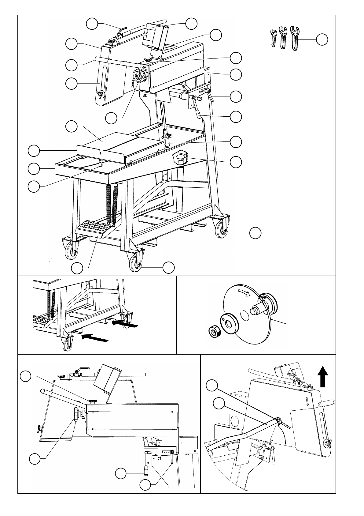
FIG. 1
ABB. 1
FIG. 3
ABB. 3
FIG. 2
ABB. 2
FIG. 4
ABB. 4
B
J
K
A
7
10
20
12
11
15
1
16
14
6
13
18
21
17
19
5
9
4
8
2
3
FIG. 5
ABB. 5
A
B
Page 6
• Utilisation : sciage de hourdis, parpaing,
béton cellulaire, brique réfractaire, etc...
Interdiction de toute autre application ne
correspondant pas à l'utilisation prévue
(emploi de lame de scie, de disque
abrasif...).
1
Emploi
• Transportable par 4 roues.
• Blocage des roues AV.
• Rail pour fourche.
• Vitesse de rotation de la broche :
- version électrique : 1600 tr/mn
- version thermique : 2045 tr/mn
• Protection électrique : IP 55.
• Profondeur de coupe :
- 160 mm avec Ø 400 mm
- 180 mm avec Ø 450 mm
- 200 mm avec Ø 500 mm
- 240 mm avec Ø 600 mm
• Longueur de coupe : 520 mm
• Dimensions (mm) (L x I x H) :
1400 x 690 x 1550
• Poids à vide : 150 à 175 Kg
• Refroidissement du disque par arrosage
dans carter de disque.
• Capacité mini. du bac : 57 litres
• Pompe à eau : 14 litres / minute
• Alimentation :
- 230 V : H07-RNF 3 x 1,5
2
- Lg 3 m
- 400 V : H07-RNF 5 x 1,52- Lg 3 m
- 110 V : H07-RNF 3 x 2,5
2
- Lg 3 m
2
Caractéristiques techniques
• A réception, contrôler l'état de votre
machine.
• La conserver en permanence en bon état
de propreté.
• Contrôler périodiquement le cordon
d'alimentation, la rallonge.
• Pendant le travail, rester toujours attentif.
• Vérifier la fixation des pièces (vibration
anormale), le bon montage.
Voir FIG. 1
11 - Châssis-bac
12 - Roue arrière
13 - Roue avant
14 - Pompe à eau
15 - Poignée blocage tête
16 - Volant réglable
17 - Jeu de clés
18 - Bouchon de vidange
19 - Moteur
10 - Disjoncteur
11 - Poignée de manœuvre
12 - Carter de disque
13 - Visière
14 - Table amovible
15 - Butée de table
16 - Butée de table amovible
17 - Plaque signalétique
18 - Pédale
19 - Butée
20 - Robinet
21 - Volant de serrage
Français
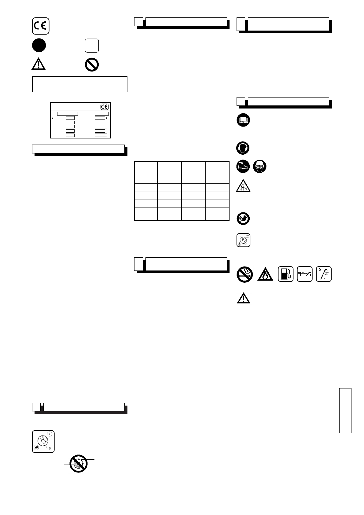
1
OBLIGATION
INDICATION
INFORMATION
INSTRUCTION
AVERTISSEMENT
INTERDICTION
Ces signes vous indiqueront les conseils
qui concernent votre sécurité
Ce symbole signifie que la
machine est conforme à la
directive européenne.
• Outils : Disques Diamantés à
Eau et à Sec
- Ø 400 à 600 mm
- alésage 25,4 mm
1,5 KW 110 V 186 70 0,21
2,2 KW 240 V 189 76 0,13
7,5 KW 440 V 186 82 0,23
HONDA
GX160
MODELE
PUISSANCE
ACOUSTIQUE
Lwa (dB)
EN ISO 3744
Lpa (dB)
EN ISO 4871
G ENV
25349
PRESSION
ACOUSTIQUE
NIVEAU DE
VIBRATION
TYPE
LE FABRICANT
MASSE UTILE Kg
mm
mm
Ø MAXI OUTIL.
Ø ALESAGE
T/MN - RPM
N° SERIE
ANNEE DE
FABRICATION
PUISSANCE kW
Hz
V
A
PLAGE DE
TENSION
FREQUENCE
INT. UTIL.
Plaque signalétique
Conçue pour assurer un service sûr et
fiable dans des conditions d'utilisation
conformes aux instructions, la
tronçonneuse peut présenter des dangers
pour l'utilisateur et des risques de
détérioration, des contrôles réguliers sur le
chantier sont nécessaires, s'assurer :
• de l'état technique parfait (utilisation
suivant affectation en tenant compte
des risques éventuels, suppression de
toute malfonction nuisible à la sécurité),
• de l'usage d'un disque diamant pour
tronçonnage à l'eau de marbre, pierre,
granit, brique, et revêtement (grès,
faïence, céramique, etc...), utilisation
interdite de tout autre disque (abrasif,
scie, etc...),
• d'un personnel compétent (qualification,
âge, formation, instruction) ayant pris
connaissance dans le détail du manuel
avant de commencer le travail ; toute
anomalie électrique, mécanique ou
d'autre origine sera contrôlée par une
personne habilitée à intervenir
(électricien, responsable de l'entretien,
agent revendeur agréé, etc...),
• s'assurer du respect des
avertissements et directives marqués
sur la machine (protections adéquates
personnelles), utilisation conforme,
instructions de sécurité en général...),
• qu'aucune modification, transformation
ou complément soit nuisible à la
sécurité et ne sera pas réalisée sans
l'autorisation du fabricant,
• du respect des fréquences de
vérifications et contrôles périodiques
préconisés,
• de la garantie de pièces de rechange
d'origine lors de réparations.
CONSIGNES PARTICULIERES
Lame de scie
Disque carbo
• Machine à moteur essence (se reporter
au livret d'entretien moteur)
-S'assurer du plein de carburant.
-Vérifier le niveau d'huile: le moteur
travaillant souvent incliné, vérifier
fréquemment, en position horizontale,
que son niveau d'huile ne soit jamais
inférieur au deuxième trait de la jauge.
-Ne pas utiliser le moteur sous son
régime, la vitesse de rotation est
donnée par la position maximum du
levier
-Pour le démarrage, se reporter à la
notice des moteurs.
Avant toute mise en service, lire
attentivement la notice, et se
familiariser avec la machine.
L'opérateur doit porter
des protections
appropriées au travail.
Toute personne étrangère doit
être écartée du champ de travail.
Obligation port du casque
antibruit.
Le champ de travail doit être
parfaitement en ordre, bien
éclairé, et ne doit présenter
aucun risque (ni-humidité, ni
produits dangereux à proximité).
Utiliser des disques adéquats
pour le travail à effectuer
(vitesse, géométrie, application,
etc...)
Tenir compte des conditions
ambiantes.
4
Manutention - Transport
[voir FIG. 2]
3
Contrôle - Description de la
machine
5
Vérification avant la mise en
route
106 94 1
Page 7
Français
2
8
Mise en service
Débrancher la tronçonneuse en
désaccouplant la fiche
d'alimentation.
Par sécurité, débrancher la
bougie.
Stocker dans un endroit sûr,
hors de portée des enfants.
Entretenir soigneusement les
outils.
"Entretien moteur" : se reporter
au livret d'entretien moteur.
Le lubrifiant sera éliminé
conformément aux modalités
prescrites par la législation en
vigueur.
Rester toujours attentif.
9
Méthode de coupe
Avant la mise en service, enlever
les clés et outils de réglage du
sol ou de la machine.
Maintenir le carter de protection
en place pendant toute la durée
du travail.
L'écrou de serrage du disque
possède un filetage avec un pas
à gauche.
Observer le sens de rotation
représenté par une flèche sur
une de ses faces
Veiller à la propreté des surfaces
d'appui du disque, des flasques
et de la broche
- S'assurer du voltage du réseau,
identique à la plaque de la
machine.
- Moteur triphasé :
S'assurer que le sens de rotation
corresponde à la flèche
emboutie sur le carter : si le
moteur ne tourne pas dans le
sens désiré, inverser deux des
fils d'alimentation.
• Devisser l'écrou de serrage à l'aide de la
clé de 36.
- Câble prolongateur : section du câble
suffisante pour la puissance électrique,
raccordement au réseau par un câble
type H07 RNF de sectionx:
- 3 x 2,5 mm
2
jusqu'à 50 m pour 230 V
- 5 x 1,5 mm2jusqu'à 100 m pour 400 V
- 3 x 4 mm
2
jusqu'à 40 m pour 110xV
• Remplir le bac d'eau (niveau maxi base
des rails).
• Pompe à eau à mise en route couplée
avec le moteur.
Chaque machine étant équipée d'une
pompe auto-amorçante, le disque est
arrosé dès la mise en marche.
Le carter protecteur et le support
moteur avec déflecteur assurent une
répartition parfaite de l'arrosage.
• Placer le matériau sur la table. Le
maintenir à deux mains. Appuyer sur la
pédale et pousser le matériau vers la
lame.
• En fonction de l'épaisseur et de la dureté
du matériau, procéder à une ou plusieurs
passes.
• Réglage millimétrique : procéder comme
ci-dessus, puis régler de + ou - 5 mm en
vissant ou dévissant le volant (J).
• Pour des plongées de profondeur
identique, débloquer le levier (K).
Actionner la pédale ou la poignée jusqu'à
la profondeur voulue. Bloquer le levier
(A). La tête ne pourra alors remonter qu'à
la hauteur fixée.
• Pour éviter que la hauteur de coupe ne
se dérègle, serrer le volant (B).
• Pour un nouveau réglage, desserrer le
levier (K).
11
Entretien
(arrêt obligatoire du moteur)
• Nettoyer régulièrement la machine.
• Vidanger fréquemment le bac pour
évacuer la boue de tronçonnage, qui
sinon risquerait de colmater la pompe de
refoulement et de l'user prématurément.
• Laver le bac à grande eau.
• Nettoyer minutieusement les portées de
galets de la table.
• Si après quelque temps d'utilisation la
tête de tronçonnage ne revient pas à sa
position initiale (position haute), il suffit de
serrer de quelques tours l'écrou qui
permet de retendre le ressort de rappel
de la tête [VOIR VUE ECLATEE].
• Moteur thermique
Se reporter aux instructions du manuel
de service du constructeur.
• Moteur thermique
Basculer l'interrupteur de la manette gaz.
• Enlever le flasque de serrage.
• Présenter le disque.
• Serrer l'écrou.
• Remettre le carter de protection en place.
• Pour le montage de disque supérieur à
500mm(FIG 5), démonter la vis A pour
désolidariser la tige B.Basculer le carter
de disque en arrière.
7
Raccordement électrique
- SECURITE ELECTRIQUE :
Obligation de branchement sur un
réseau équipé d'un disjoncteur à
courant différentiel résiduel
30xmA avec mise à la terre. Dans
le cas d'absence de ce
disjoncteur sur le réseau,
consulter notre catalogue
proposant différents modèles.
- Utilisation correcte du dispositif
à courant différentiel résiduel
incluant son contrôle
périodique; pour les outils
fournis avec un DCDR
(dispositif à courant différentiel
résiduel) intégré dans le câble
ou dans la fiche pour prise de
courant, dans l'hypothèse où le
câble ou la prise sont
endommagés, la réparation doit
être effectuée par le fabricant ou
un de ses agents ou par un
atelier de réparation qualifié afin
d'éviter tout risque dû à une
réparation mal faite.
- Utiliser des prises de courant
monophasé du type 2xPx+ T, ou
3xPx+ T / 3 P + N + T suivant
tensions correspondantes.
2 P + T
230 V
H07 - RNF
3 x 2,5
2
50 M
+ (x2)
400 V
H07 - RNF
5 x 1,5
2
100 M
+ (x2)
110 V
H07 - RNF
3 x 4
2
40 M
+ (x2)
●●
●●
Arrosage abondant =
longévité assurée du disque
• Moteur électrique
Mettre en marche en appuyant
sur la touche disjoncteur.
• Moteur électrique
Pour arrêter la tronçonneuse,
appuyer sur la touche rouge.
6
Montage du disque
[voir FIG. 3]
• Le poids de la tête compensé par des
ressorts est étudié de telle sorte qu'il
suffit à l'utilisateur d'exercer une légère
pression pour régler la profondeur de
coupe.
• Verrouillage de la tête : débloquer le
levier de butée (K), appuyer sur la pédale
de façon à ce que le disque soit à la
profondeur désirée et rebloquer.
10
Réglage de profondeur
[voir FIG. 5]
Page 8
RECHERCHE DES PANNES
En cas de fonctionnement anormal, se
reporter aux tableaux ci-après pour trouver
une solution aux problèmes rencontrés.
• La machine ne fonctionne pas
• Dévisser les 4 vis de fixation et enlever la
fermeture du support de broche.
• Desserrer à l'aide de la clé de 19 la vis de
serrage du boîtier.
• A l'aide d'un levier, retendre la courroie. Si
cela reste insuffisant, agir sur le moteur
(lumières dans support moteur), puis fixer
le boîtier
12
Changement de courroie
• Afin d'éviter la poussière et l'échauffement
du disque, chaque tronçonneuse est
montée avec pompe.
• Dès la mise en marche, le disque est
arrosé.
13
Arrosage du disque
• La machine étant réglée en nos ateliers,
aucun réglage n'est nécessaire.
• Toutefois, en cas de chocs, de
desserrage de boulonnerie, de
manœuvres brutales lors du pivotement
de la tête, agir sur la vis de butée et
vérifier l'équerrage (pour coupes
rectilignes).
14
Réglages
• Resserrer périodiquement la boulonnerie.
• En cas de longue période d'utilisation,
veiller à l'entretien et à la protection du
disque.
• Veiller à l'arrosage adéquat du disque.
• Effectuer un serrage correct du disque.
• Veiller à la propreté des surfaces d'appui
du disque, des flasques et de la broche.
15
Recommandations importantes
Français
3
CAUSES
Mauvais
branchement ou
câble endommagé
Pas de tension sur
le réseau
Commutateur
défectueux, câble
moteur
endommagé
Moteur
endommagé (pas
de puissance,
odeur
désagréable...)
- S'assurer du
branchement
correct à
l'alimentation
(fiche,
rallonge...).
- Vérifier le câble
d'alimentation
- Vérifier ou faire
vérifier par un
électricien
(disjoncteur,
prise...).
- Faire vérifier par
un électricien ou
s'adresser au
service aprèsvente.
- Remplacer le
moteur en
s'adressant au
service aprèsvente.
REMEDES
• Démarrage difficile
CAUSES
Condensateur
démarrage moteur
monophasé
Alimentation
triphasé non
conforme (sur 2
phases, moteur
câble détérioré)
- Remplacer le
condensateur.
- Faire vérifier par
un électricien ou
contacter le
service après
vente.
REMEDES
• La pompe ne part pas
CAUSES
Le câble d'alimentation n'est pas
relié ou est
endommagé
Il n'y a pas de
tension dans le
circuit ou à la prise
de courant
- Contrôler ou
faire contrôler le
câble
d'alimentation.
- Vérifier ou faire
contrôler le
circuit ou la prise
de courant.
REMEDES
• Le liquide ne sort pas de la pompe
CAUSES
Une bulle d'air a pu
se former à
l'intérieur du corps
de la pompe
La turbine est
bloquée
- Extraire la
pompe du
liquide, en la
soutenant par le
tuyau de sortie,
puis la replonger
dans le liquide.
- Dévisser le filtre
et, à l'aide d'un
petit tournevis,
nettoyer la zone
de travail de la
turbine de tout
résidu.
REMEDES
Le fabricant décline toute
responsabilité résultant d'un
emploi inadapté, de toute
modification, adaptation ou
motorisation non conforme à la
définition d'origine prévue par le
constructeur.
Au poste de travail, la puissance
sonore peut dépasser 85 db (A).
Dans ce cas, des mesures
individuelles de protection
doivent être prises.
16
Réparation
Vous adresser à votre
fournisseur qui est à votre entière
disposition pour vous assurer
toute réparation dans les délais
les plus réduits et aux meilleurs
prix.
S
A
V
17
Pièces de rechange
Pour une livraison rapide des pièces de
rechange et afin d'éviter toute perte de
temps, il est nécessaire de rappeler à votre
fournisseur lors de chaque commande les
indications qui figurent sur la plaque
signalétique de la machine, ainsi que la
référence de la pièce à remplacer.
Voir vue éclatée
00000000 (0)
Code Quantité
Les conseils d'utilisation et pièces détachées
figurant sur ce document sont donnés à titre
d'information et non d'engagement.
Soucieux de la qualité de nos produits, nous nous
réservons le droit d'effectuer, sans préavis, toutes
modifications techniques en vue de leur
amélioration.
En cas de détérioration et de
casse de la machine, ceux-ci
seront éliminés conformément
aux modalités prescrites par la
législation en vigueur.
18
Mise au rebut
• Matériaux principaux :
- Moteur : Aluminium (AL) - Acier (AC)
- Moteur : Cuivre (CU) - Polyamide (PA)
- Machine : Tôle acier (AC) - Fonte (FT)
Page 9
• Uso : taglio di tavelloni, pomice, calcestruzzo
cellulare, mattoni refrattari, ecc.
Interdizione di qualsiasi altra
applicazione non corrispondente
all'utilizzo previsto (impiego di lama di
sega, di disco abrasivo).
1
Impiego
• Trasportabile su 4 ruote.
• Bloccaggio delle ruote anteriori (AV)
• Rotaia forcella
• Velocità di rotazione : :
- versione elettrica : 1600 g/min.
- versione termica : 2045 g/min.
• Protezione elettrica : IP 55.
• Profondità di taglio :
- 160 mm con Ø 400 mm
- 180 mm con Ø 450 mm
- 200 mm con Ø 500 mm
- 240 mm con Ø 600 mm
• Lunghezza di taglio : 520 mm
• Dimensioni (mm) (L x I x A) :
1400 x 690 x 1550
• Peso a vuoto : 150 à 175 Kg
• Raffreddamento del disco mediante
innaffiatura nel carter del disco.
• Capacità minima del serbatoio : 57 litri
• Pompa per acqua : 14 l/min.
• Alimentazione :
- 230 V : H07-RNF 3 x 1,5
2
- Lungh. 3 m
- 400 V : H07-RNF 5 x 1,52- Lungh. 3 m
- 110 V : H07-RNF 3 x 2,5
2
- Lungh. 3 m
2
Caratteristiche tecniche
5
Verifica prima dell'avviamento
• Al ricevimento della macchina, controllare
lo stato della stessa.
• Conservarla permanentemente in un
perfetto stato di pulizia.
• Controllare periodicamente il cavo
d'alimentazione e la prolunga.
• Durante il lavoro, prestare la massima
attenzione.
• Verificare il fissaggio dei pezzi (vibrazione
anormale) e il corretto montaggio dei
dischi (piattaforme).
VEDI FIG. 1
11 - Telaio-serbatoio
12 - Ruota posteriore
13 - Ruota anteriore
14 - Pompa per acqua
15 - Leva bloccaggio testa
16 - Volante regolabile
17 - Set di chiavi
18 - Tappo di scarico
19 - Motore
10 - Interruttore
11 - Leva di manovra
12 - Carter del disco
13 - Visiera
14 - Tavola amovibile
15 - Arresto tavola
16 - Arresto tavola amovibile
17 - Targhetta segnaletica
18 - Pedale
19 - Arresto
20 - Rubinetto
21 - Volante di serraggio
4
OBBLIGO
INDICAZIONE
INFORMAZIONE
ISTRUZIONI
OPERATIVE
AVVERTENZA
DIVIETO
Questi simboli sono destinati ad evidenziare i
consigli che interessano la vostra sicurezza
Questo simbolo indica che la
macchina è conforme alla direttiva
europea.
• Utensile : Dischi Diamantati
ad unido e a secco
- de Ø 400 a 600 mm
- foro 25,4 mm
Progettata per assicurare un servizio sicuro ed
affidabile in condizioni d'utilizzo conformi alle
istruzioni, la troncatrice può tuttavia presentare
pericoli per l'operatore ed essere soggetta a rischi
di deterioramento. Pertanto, si rendono necessari
controlli regolari sul cantiere. In particolare,
verificare :
• il perfetto stato della macchina sotto il
profilo tecnico (utilizzo conforme alle
specifiche di progettazione, tenendo conto
degli eventuali rischi; soppressione di
qualsiasi malfunzionamento che
comprometta la sicurezza),
• che venga utilizzato un disco diamante per
troncatura con getto d'acqua di marmo,
pietre, granito, mattoni e rivestimenti (grès,
faenze, ceramica, ecc...) all'acqua; è vietato
l'utilizzo di qualsiasi altro disco (abrasivo,
sega, ecc...)
• la presenza di personale competente
(qualificazione, età, formazione, istruzione)
che abbia preso conoscenza del manuale
nei minimi dettagli prima di iniziare il lavoro;
qualsiasi anomalia elettrica, meccanica o di
altra origine verrà controllata da una
persona abilitata ad intervenire (elettricista,
responsabile della manutenzione, agente
del rivenditore autorizzato, ecc...)
• il rispetto delle avvertenze e delle direttive
riportate sulla macchina (uso di protezioni
personali appropriate, impiego conforme,
istruzioni di sicurezza in generale...),
• che nessuna modifica, trasformazione o
aggiunta comprometta la sicurezza;
qualsiasi intervento del genere potrà essere
effettuato solo previa autorizzazione da
parte del fabbricante,
• il rispetto della frequenza delle verifiche e
dei controlli periodici raccomandati,
• la garanzia dei pezzi di ricambio originali
durante le riparazioni.
ISTRUZIONI SPECIALI
Lama di sega
Disco
carbone
• Macchina con motore a benzina (riferirsi
al manuale di manutenzione motore)
- Assicurarsi che vi sia carburante.
- Verificare il livello dell’olio; poiché il
motore spesso lavora inclinato
verificare frequentemente, portandolo
in posizione orizzontale, che il livello
dell’olio non sia mai inferiore alla
seconda tacca dell’indicatore.
- Non utilizzare il motore al di sotto del
suo regime, la velocità di rotazione
viene data dalla posizione massima
della leva.
- Per l’avviamento, riferirsi al manuale
motori.
Prima della messa in funzione,
leggere attentamente l'istruzione
d'uso e prendere confidenza con
la macchina.
L'operatore deve portare
protezioni appropriate.
Non permettere ad altre persone
di rimanere vicino alla sega
quando taglia.
Obbligo di mettere il casco
antirumore.
Tenere il campo di lavoro
perfettamente in ordine, bene
illuminate e senza rischio
(umidità, prodotti pericolosi nelle
vicinanze).
Utilizzare esclusivamente dischi
adatti al tipo di lavoro da
eseguire (velocità, geometria,
applicazioni, ecc.)
Tenere conto delle condizioni
ambientali.
4
Movimentazione - Trasporto
[VEDI FIG. 2]
3
Controllo Descrizione della macchina
Italiano
TYPETIPO SERIE
POTENZIA
TENSIONE
FREQUENCA
INTENSITA
ANNO
FABRICAZIONNE
PESO
ALESAGGIO
MASSIMO
USTENSILE
GIRI/MIN VELOCITA
DI ROTATIONE
IL FABBRICANTE
MASSE UTILE Kg
mm
mm
Ø MAXI OUTIL.
Ø ALESAGE
T/MN - RPM
N° SERIE
ANNEE DE
FABRICATION
PUISSANCE kW
Hz
V
A
PLAGE DE
TENSION
FREQUENCE
INT. UTIL.
Targhetta segnaletica
1,5 KW 110 V 186 70 0,21
2,2 KW 240 V 189 76 0,13
7,5 KW 440 V 186 82 0,23
HONDA
GX160
MODELLO
POTENZA
ACUSTICA
Lwa (dB)
EN ISO 3744
Lpa (dB)
EN ISO 4871
G ENV
25349
PRESSIONE
ACUSTICA
LIVELLO DI
VIBRAZIONE
106 94 1
Page 10
5
8
Messa in servizio
Mettere fuori tensione la troncatrice
staccando la spina d'alimentazione.
Per sicurezza, staccare la
candela.
Stoccare in un posto sicuro,
fuori dalla portata dei bambini
Avere cura degli utensili
"Manutenzione motore": fare
riferimento al manuale di
manutenzione motore.
Il lubrificante verrà eliminato
conformemente alle modalità
prescritte dalla legislazione in
vigore.
Essere sempre attenti
9
Metodo di taglio
Prima dell'avviamento, togliere le
chiave e gli utensili di
regolazione
Mettere sempre i carter di
protezione
Il dado di serraggio del disco
possiede una filettatura
sinistrorsa.
Attenzione al senso di rotazione,
indicato con una freccia su uno
dei lati del disco.
Verificare la pulizia delle facce
d'appoggio delle flange, del
disco e dell'albero.
- Assicurarsi che la tensione della
rete sia identica a quella indicata
sulla targhetta della macchina.
- Motore trifase :
Assicurarsi che il senso di
rotazione corrisponda alla
freccia disegnata sul carter. Se il
motore non gira nel senso
voluto, invertire due dei fili di
alimentazione.
• Allentare il dado di serraggio per mezzo
della chiave da 36.
- Cavo di prolunga : sezione del cavo
sufficiente per la potenza elettrica,
collegamento alla rete mediante un cavo
tipo H07 RNF di sezione:
- 3 x 2,5 mm
2
fino a 50 m per 230 V
- 5 x 1,5 mm2fino a 100 m per 400 V
- 3 x 4 m m
2
fino a 40 m per 115 V
• Riempire il serbatoio d'acqua (livello max.
base delle guide di scorrimento).
• Pompa per acqua con avviamento
accoppiato con il motore.
Questa macchina essendo dotata di una
pompa auto-adescante, il disco viene
innaffiato sin dall'avviamento.
Il carter di protezione ed il supporto motore
con deflettore assicurano una perfetta
distribuzione dell'innaffiatura.
• Posizionare il materiale sul tavolo.
Tenerlo saldamento con le due mani.
Premere il pedale e springere
simultaneamente il materiale verso la
lama.
• A seconda dello spessore a della durezza
del materiale, effettuare 1 o più passaggi.
• Regolazione millimetrica : procedere
come sopra indicato, quindi regolare di +
0 - 5 mm avvitando o svitando il volano
(J).
• Per ottenere profondità identiche,
sbloccare la leva (K). Azionare il pedale
oppure l’impugnatura fino al
raggiungimento della profondità voluta.
Bloccare la leva (A). A questo punto la
testa non potrà far altro che riportarsi
all’altezza prestabilita.
• Per evitare che l’altezza di taglio non
subisca variazioni, stringere il volante (B).
• Per effettuare una nuova regolazione,
svitare la leva (K).
11
Manutenzione
(arresto del motore obbligatorio)
• Pulire regolarmente la macchina.
• Scaricare spesso il serbatoio per togliere
il fango di taglio, che, altrimenti, rischia di
intasare la pompa di mandata e di
usurarla prematuramente.
• Pulire il serbatoio con acqua.
• Pulire accuratamente le sedi delle rotelle
della tavola.
• Se dopo un certo tempo di utilizzo, la
testa di taglio non ritorna nella sua
posizione iniziale (posizione alta), basta
stringere di alcuni giri il dado che
permette di tendere la molla di richiamo
della testa [VEDI SPACCATO].
• Motore termico
Riferirsi alle istruzioni del manuale di
servizio del costruttore.
• Motore termico
Ruotare l’interruttore della leva gas.
• Togliere la flangia di serraggio.
• Montare il disco.
• Serrare il dado.
• Riposizionare il riparo e fissarlo.
• Per il montaggio del disco superiore a
500 mm (FIG. 5), smontare la vite A per
disimpegnare l'asta B. Ribaltare il carter
del disco.
7
Collegamento elettrico
- SICUREZZA ELETTRICA :
Obbligo di collegamento ab un
interuttore a corrente differenziale
residua 30 mA con messa a terra.
In mancanza di quest'interruttore
sulla rete, consultare il nostro
catalogo per i differenti modelli
proposi.
- Uso corretto del dispositivo a
corrente differenziale residua
comprendente il suo controllo
periodico. Per gli utensili forniti
con un DCDR integrato nel
cavo o nella spina per presa di
corrente, nell’ipotesi in cui il
cavo o la presa siano
danneggiati, la riparazione
deve essere effettuata a cura
del costruttore, da uno degli
agenti o da un atelier di
riparazione qualificato, per
evitare ogni rischio causato da
una cattiva riparazione.
- Utilizzare prese di corrente
monofase di tipo 2 P + T, o
3xPx+xT / 3xPx+xNx+xT a
seconda delle relative tensioni.
2 P + T
230 V
H07 - RNF
3 x 2,5
2
50 M
+ (x2)
400 V
H07 - RNF
5 x 1,5
2
100 M
+ (x2)
110 V
H07 - RNF
3 x 4
2
40 M
+ (x2)
●●
●●
Umidificazione abbondante =
longevità garantita del disco
Azionare la macchina premendo il
tasto dell’interruttore.
• Motore elettrico
Per fermare la troncatrice,
premere il tasto rosso.
6
Montaggio del disco
[VEDI FIG. 3]
• Il peso della testa caricata a molla è stato
studiato in modo che basti una lieve
pressione da parte dell'utilizzatore per
regolare la profondità di taglio.
• Chiusura della testa : sbloccare la leva
dell’arresto (K), premere il pedale in
modo tale che il disco venga a trovarsi
alla profondità desiderata e quindi
ribloccare.
10
Regolazione della profondità
[VEDI FIG. 5 ]
Italiano
Page 11

• Svitare le 4 viti di fissaggio e togliere la
chiusura del supporto mandrino.
• Allentare con la chiave da 19 la vite di
fissaggio della custodia
• Servendosi di una leva, tendere la
cinghia. Se non basta, agire sul motore
(apposite luci nel supporto motore), quindi
sulla custodia.
• Per evitare la polvere e il
surriscaldamento del disco, ogni
troncatrice è equipaggiata con una pompa
ad acqua.
• Non appena la macchina viene avviata, il
disco viene bagnato.
13
Umidificazione del disco
• La macchina essendo regolata nelle
nostre officine, nessuna regolazione è
necessaria.
• Tuttavia in caso di urti, di allentamento
della bulloneria, di manovre brusche
durante l'inclinazione della testa, agire
sulle viti di arresto (J) e verificare
l'apertura angolare (per tagli rettilinei).
14
Regolazioni
• Tringere periodicamente la bulloneria.
• In caso di arresto prolungato e di non
utilizzo della macchina, si raccomanda di
togliere il disco e di conservarlo
adeguatamente.
• Procedere all'innaffiattura adeguata del
disco.
• Eseguire un serraggio corretto del disco.
• Curare la pulizia delle superfici di
appoggio del disco, delle flange e del
mandrino.
15
Raccomandazioni importanti
6
Il costruttore declina ogni
responsabilità derivante da un
uso non corretto, da qualsiasi,
modifica, adattamento o
motorizzazione diversi da quanto
specificatamente previsto in
origine dal costruttore stesso.
Sul posto di lavoro il livello di
pressione acustica può superare
85 db (A).
Il tal caso bisogna prendere delle
misure individuali di protezione.
16
Riparazioni
Siamo a Vostra completa
disposizione per garantir Vi
qualsiasi riparazioni nei tempi più
brevi e ai prezzi migliori (vedere
l'indirizzo sul retro).
S
A
V
17
Pezzi di ricambio
Per una consegna rapida dei pezzi di
ricambio, ed onde evitare qualsiasi perdita
di tempo, è necessario richiamare su ogni
ordine le indicazioni che figurano sulla
targhetta segnaletica della macchina
nonchè il numero di riferimento del pezzo
da sostituire.
Le notizie tecniche sono date a titolo
informativo e non vincolano il costruttore.
Per migliorare costantemente la qualità del
nostro prodotti ci riserviamo di apportare
modifiche senza preaviso.
In caso di deterioramento degli
accessori o dell'intera macchina,
questa verrà buttata secondo i
metodi prescritti dalla
legislazione in vigore.
18
Scarto
• Materiali principali :
- Motore : Alluminio (AL) - Acciaio (AC)
Motore : Rame (CU) - Poliammide (PA)
- Macchina : Lamiera acciaio (AC)
- Macchina : Ghisa (FT)
Italiano
Vedi spaccato
00000000 (0)
Codice Quantità
RICERCA GUASTI
In caso di funzionamento anomalo, fare
riferimento alle tabelle di cui sotto per trovare
una soluzione ai problemi riscontrati.
• La macchina non funziona
CAUSE
Allacciamento
scorretto o cavo
danneggiato
Nessuna tensione
sullarete
Commutatore
difettoso, cavo
motore
danneggiato
assistenza
Motore
danneggiato
(nessuna potenza,
odore sgradevole)
- Verificare il
corretto
allacciamento
dell'alimentazion
e (spina,
prolunga,...)
- Verificare il cavo
d'alimen tazione
- Verificare o far
verificare da un
elettricista
(interruttore,
presa...)
- Far verificare da
un elettricista o
rivolgersi al
servizio
- Sostituire il
motore
rivolgendosi al
servizio
assistenza
RIMEDI
• Avviamento difficile
CAUSE
Condensatore
avviamento motore
monofase
Alimentazione
trifase non
conforme (su 2
fasi, motore cavo
danneggiato)
- Sostituire il
condensatore
- Far verificare da
un elettricista o
contattare il
servizio
assistenza.
RIMEDI
• La pompa non parte
CAUSE
Il cavo di alimentazione è mal
collegato o
danneggiato
Non c'è tensione
nel circuito o alla
presa di corrente
- Controllare o
fare controllare il
cavo di
alimentazione.
- Verificare o fare
controllare il
circuito o la presa
di corrente.
RIMEDI
• Non fuoriesce liquido dalla pompa
CAUSE
Potrebbe essersi
formata una bolla
d'aria all' interno
del corpo pompa
La turbina è
bloccata
- Estrarre la
pompa dal
liquido, sorreggendola per il
tubo di uscita,
quindi reimmergerla nel
liquido.
- Svitare il filtro e
con un piccolo
cacciavite pulire
la zona di lavoro
della turbina da
eventuali residui.
RIMEDI
12
Sostituzione della cinghia di
trasmissione
Page 12

• Utilización : Aserrado de cascotes, sillares,
hormigón celular, ladrillo refractario, etc.
Se prohibe cualquier otra aplicación que
no corresponda a la utilización prevista
(utilización de hoja de sierra, disco
abrasivo, etc.).
1
Empleo
• Transportable por 4 ruedas.
• Bloqueo de las ruedas delanteras.
• Raíl para horquilla.
• Velocidad de rotación de la broca :
- en versión eléctrica : 1600 r/min.
- en versión térmica : 2045 r/mn
• Protección elèctrica : IP 55.
• Profundidad de corte :
- 160 mm con Ø 400 mm
- 180 mm con Ø 450 mm
- 200 mm con Ø 500 mm
- 240 mm con Ø 600 mm
• Longitud de corte : 520 mm
• Dimensiones (mm) (l x a x h) :
1400 x 690 x 1550
• Peso en vacío : 150 à 175 Kg
• Refrigeración del disco por riego en el
cárter de disco.
• Capacidad mínima del depósito : 57 litros
• Bomba de agua : 14 l/min.
• Alimentación :
- 230 V : H07-RNF 3 x 1,5
2
- Long 3 m
- 400 V : H07-RNF 5 x 1,52- Long 3 m
- 110 V : H07-RNF 3 x 2,5
2
- Long 3 m
2
Características técnicas
• Comprobar el estado de la máquina en el
momento de su recepción.
• Conservarla constantemente en buen
estado de limpieza.
• Comprobar periódicamente el cable de
alimentación y el prolongador.
• Permanecer siempre muy atento durante
el trabajo .
• Comprobar si la fijación de las piezas
(vibración anormal) y el montaje de los
platos son correctos.
VEASE FIG. 1
11 - Chasis - depósito
12 - Rueda trasera
13 - Rueda delantera
14 - Bomba de agua
15 - Empuñadura de bloqueo cabeza
16 - Volante regulable
17 - Juego de llaves
18 - Tapón de vaciado
19 - Motor
10 - Disyuntor
11 - Empuñadura de maniobra
12 - Cárter de disco
13 - Visera
14 - Mesa desmontable
15 - Tope de mesa
16 - Tope de mesa desmontable
17 - Placa de características
18 - Pedal
19 - Tope
20 - Llave
21 - Volante de apriete
7
OBLIGACIÓN
INDICACIÓN
INFORMACIÓN
INSTRUCCIÓN
ADVERTENCIA
PROHIBICIÓN
Estos símbolos le señalan diferentes
recomendaciones para garantizar su seguridad
Este anagrama certifica que la
máquina cumple la normativa
europea.
• Herramientas :
Discos diamantados en agua o
en seco.
- Ø 400 a 600 mm
- Calibre 25,4 mm
Diseñado para efectuar un servicio seguro y
fiable en condiciones de utilización conformes
a las instrucciones, el cortador puede
presentar peligros para el usuario y riesgos de
deterioro. Por tanto, es necesario realizar
controles regulares en la obra. Verificar :
• que el estado técnico es perfecto
(utilización según el destino, teniendo en
cuenta los riesgos eventuales, y
supresión de todo disfuncionamiento
perjudicial para la seguridad),
• que se utiliza un disco de diamante
para corte con agua de mármol, piedra,
granito, ladrillo y revestimiento (gres,
loza, cerámica, etc.). Se prohíbe la
utilización de cualquier otro disco
(abrasivo, sierra, etc.),
• que el personal es competente
(cualificación, edad, formación,
instrucción) y que haya estudiado
detalladamente el manual antes de
comenzar el trabajo. Toda anomalía
eléctrica, mecánica o de otro tipo, será
controlada por una persona habilitada
para la intervención (electricista,
responsable del mantenimiento, agente
revendedor acreditado, etc.),
• que se respetan las advertencias y
directivas marcadas en la máquina
(protecciones personales adecuadas),
utilización conforme, instrucciones de
seguridad en general, etc.),
• que no hay ninguna modificación,
transformación o complemento
perjudicial para la seguridad, y no será
realizada sin la autorización del
fabricante,
• el cumplimiento de las frecuencias de
verificaciones y controles periódicos
preconizados,
• la garantía de piezas de recambio de
origen durante las reparaciones.
CONSIGNAS PARTICULARES
Hoja de sierra
Disco carbo
3
Control - Descripción de la
máquina
4
Manutención - Transporte
[VEASE FIG. 2]
• Máquina con motor de gasolina
(remitirse al libro de mantenimiento
motor).
- Comprobar si se ha llenado el depósito
de carburante.
- Verificar el nivel de aceite. Cuando el
motor trabaja a menudo inclinado,
comprobar frecuentemente, en posición
horizontal, que su nivel de aceite nunca
es inferior a la segunda marca del
indicador de nivel.
- No utilizar el motor por debajo de su
régimen; la velocidad de rotación la da
la posición máxima de la palanca.
- Para la puesta en marcha, remitirse a
las instrucciones de los motores.
Antes de la puesta en marcha,
leer detenidamente las
instrucciones y familiarizarse
con la máquina.
Llevar las protecciones
propias de su trabajo
Alejar a toda persona, ajena a la
obra
Es obligatorio el uso del caso
antiruidos.
El campo de trabajo debe estar
perfectamente en orden, bien
iluminado y no debe presentar
ningún riesgo o peligro. (Ni
humedad, ni productos
peligrosos cerca)
Utilizar los discos apropiados
para el trabajo a realizar
(velocidad, geometría,
aplicación, etc..).
Tener en cuenta las condiciones
ambientales.
5
Verificación antes de la puesta
en marcha
Español
1,5 KW 110 V 186 70 0,21
2,2 KW 240 V 189 76 0,13
7,5 KW 440 V 186 82 0,23
HONDA
GX160
MODELO
NIVEL
SONORO
Lwa (dB)
EN ISO 3744
Lpa (dB)
EN ISO 4871
G ENV
25349
NIVEL
ACUSTICO
NIVEL DE
VIBRACIÓN
106 94 1
TYPETIPO SERIE
POTENCIA
TENSION
FRECUENCIA
INTENSITAD
AÑO
FABRICACION
PESO
ESE
MAXI
UTENSILIO
VELOCIDAD
DE ROTACION
EL FABRICANTE
MASSE UTILE Kg
mm
mm
Ø MAXI OUTIL.
Ø ALESAGE
T/MN - RPM
N° SERIE
ANNEE DE
FABRICATION
PUISSANCE kW
Hz
V
A
PLAGE DE
TENSION
FREQUENCE
INT. UTIL.
Placa de caracteristicas
Page 13

8
8
Puesta en servicio
6
Montaje del disco
Desenchufar el cortador
desacoplando el enchufe de
alimentación.
Por seguridad, desconectar la
bujía.
Guardar en un lugar seguro,
fuera del alcance de los niños.
Efectuar un mantenimiento
cuidadoso de las herramientas.
"Mantenimiento motor":
remitirse al manual de
mantenimiento del motor.
El lubricante se eliminará de
conformidad con las
modalidades prescritas por la
legislación vigente.
Este siempre atento
9
Método de corte
Antes de la puesta en marcha,
quitar las llaves y útiles de
reglaje
Tener siempre colocados los
protectores
La tuerca de apriete del disco
tiene un roscado con paso a la
izquierda.
Tener en cuenta el sentido de
rotación, marcado por una flecha
en una de sus caras.
Verificar el estado y limpieza de
las caras de los platos.
- Cerciorarse de que el voltaje de
la red es idéntico al de la placa
de la máquina.
- Motor trifásico :
Cerciorarse de que el sentido de
rotación corresponde a la flecha
embutida en el cárter: si el motor
no gira en el sentido deseado,
invertir dos hilos de
alimentación.
• Desenroscar la tuerca de apriete con la
llave de 36.
- Cable prolongador: cable de sección
suficiente para la potencia eléctrica,
conexión a la red por medio de un cable
tipo H07 RNF de sección :
- 3 x 2,5 mm
2
hasta 50 m para 230 V
- 5 x 1,5 mm2hasta 100 m para 400 V
- 3 x 4 mm
2
hasta 40 m para 115 V
• Llenar el depósito de agua (nivel máximo
base de los carriles).
• Bomba de agua con puesta en marcha
acoplada con el motor.
Dado que cada máquina está equipada
con una bomba autocebante, el disco es
refrigerado desde la puesta en marcha.
El cárter protector y el soporte motor
con deflector garantizan un perfecto
reparto del riego.
• Coloque el material a cortar en la tabla.
Sosténgalo con las dos manos. Empuje
el pedal y acerque el material al filo del
disco.
• En función del espesor y la dureza del
material, realice la operación una o varias
veces.
• Regulación milimétrica : proceda como
hemos señalado y regule a continuación
más o menos 5 mm, atornillando o
desatomillando el volante (J).
• Para penetraciones de idéntica
profundidad, desbloquear la palanca (K).
Accionar el pedal o la empuñadura hasta
la profundidad deseada y bloquear la
palanca (A). Entonces, el cabezal sólo
podrá subir hasta la altura fijada.
• Para evitar que la altura de corte se
desajuste, apretar el volante (B).
• Para un nuevo reglaje, aflojar la palanca
(K).
11
Mantenimiento
(parada obligatoria del motor)
• Limpiar regularmente la máquina.
• Vaciar frecuentemente el depósito para
evacuar el lodo de corte que, de lo
contrario, podría atascar la bomba de
descarga y gastarla prematuramente.
• Lavar el recipiente con abundante agua.
• Limpiar minuciosamente los asientos de
rodillos de la mesa.
• Si al cabo de algún tiempo de utilización
la cabeza de corte no vuelve a su
posición inicial (posición alta), basta con
apretar unas vueltas la tuerca que
permite tensar el muelle de reposición de
la cabeza [VEASE DESPIECE].
• Motor térmico
Remitirse a las instrucciones del manual
de servicio del constructor.
• Motor térmico
Bascular el interruptor de la manecilla de
gas.
• Retirar la brida de apriete.
• Presentar el disco.
• Apretar la tuerca.
• Colocar el cárter de protección.
• Para el montaje del disco superior a
500mm (FIG 5), desmontar el tornillo A
para desolidarizar la varilla B. Volcar el
cárter del disco hacia atrás.
7
Conexiones electricas
- SEGURIDAD ELECTRICA :
La conexión debe realizarse a un
cuadro con disyuntor diferencial
residual de 30 mA con toma de
tierra. En caso de que no tenga
ese tipo de disyuntor, consulte
nuestro catálogo en el cual le
proponemos varios modelos.
- Utilización correcta del
dispositivo de corriente
diferencial residual que incluye
su control periódico. En el
caso de herramientas
suministradas con un DCDR
integrado en el cable o en el
enchufe para toma de
corriente, si el cable o la toma
están deteriorados, la
reparación debe ser realizada
por el fabricante, uno de
nuestros agentes o por un
taller de reparación cualificado,
para evitar todo riesgo
resultante de una intervención
mal efectuada.
- Utilizar tomas de corriente
monofásica del tipo 2 P + T, o
3xPx +xTx/ x3xPx +xNx+ xT
según las tensiones
correspondientes.
2 P + T
230 V
H07 - RNF
3 x 2,5
2
50 M
+ (x2)
400 V
H07 - RNF
5 x 1,5
2
100 M
+ (x2)
110 V
H07 - RNF
3 x 4
2
40 M
+ (x2)
●●
●●
La duración de su disco dependera
mucho de su refrigeración
que debe ser muy abundante
• Motor eléctrico
Poner en marcha pulsando la
tecla disyuntor.
• Motor eléctrico
Parar el cortador pulsar la tecla
roja.
• El peso de la cabeza, compensado por
muelles, está diseñado de tal forma que
es suficiente una ligera presión para
regular la profundidad de corte.
• Bloqueo del cabezal : Desbloquear la
palanca de tope (K), apretar el pedal
hasta que el disco esté a la profundidad
deseada, y volver a bloquear.
10
Ajuste de profundidad
[VEASE FIG. 5]
Español
Page 14

• Afloje los 4 tornillos de fijación y quite el
cierre del soporte de la broca.
• Afloje el tornillo de fijación del cuadro de
mandos con la ayuda de la llave del 19.
• Con la ayuda de una palanca, vuelva a
tender la correa. Si esto es insuficiente,
actúe sobre el motor (luces en el soporte
del motor) y a continuación sobre el
cuadro de mandos.
12
Cambio de correa
• Con el fin de evitar el polvo y el
calentamiento del disco, todas las sierras
están equipadas con bomba.
• Desde la puesta en marcha, se riega el
disco.
13
Riego del disco
• Dado que la máquina ha sido ajustada en
nuestros talleres, no es necesario
efectuar ningún ajuste.
• No obstante, en caso de impactos,
aflojamiento de la tornillería o maniobras
bruscas durante el giro de la cabeza,
manipular el tornillo de tope (J) y verificar
el escuadradro (para cortes rectilíneos).
14
Ajustes
• Apretar periódicamente la tornillería.
• En caso de un largo periodo de
utilización, efectuar el mantenimiento
proteger el disco.
• Comprobar la correcta refrigeración del
disco.
• Apretar correctamente el disco.
• Comprobar la limpieza de las superficies
de apoyo del disco, de las bridas y del
husillo.
15
Recomendaciones importantes
9
El fabricante no se
responsabiliza de los daños
causados en caso de utilización
inadaptada, modificación,
adaptación o motorización no
conforme a la definición de
origen prevista por el fabricante.
En el puesto de trabajo, el nivel
de intensidad acústica no debe
pasar los 85 db (A).
En este caso, se deberán utilizar
medidas individuales de
protección.
16
Reparaciones
Estamos a su entera disposición
para asegurarle todas las
reparaciones en el plazo más
breve posible, y a los mejores
precios (ver dirección al reverso).
S
A
V
17
Piezas de recambio
Para una entrega rápida de las piezas de
recambio, y con el fin de evitar cualquier
contratiempo, es necesario especificar en
cada pedido las indicaciones que figuran
en la placa que contiene la descripción de
la máquina, aso como la referencia de la
pieza que se va a reemplazar.
Los consejos de utilización y repuestos que
se encuentran sobre este documento son
dados para su informatión y no como
promesa.
Preocupados por la calidad de nuestros
productos, nos reservamos el derecho de
efectuar, sin previo aviso, todas las
modificaciones tecnicas en fig. de su
mejoramiento.
En caso de deterioro y de rotura
de la máquina, ésta deberá ser
eliminada de conformidad con
las modalidades prescritas por
la legislación vigente.
18
Desecho
• Materiales principales :
- Motor : Aluminio (AL) - Acero (AC) -
Motor : Cobre (CU) - Poliamida (PA).
- Máquina : Chapa de acero (AC) -
- Máquina : Fundición (FT).
Español
BUSQUEDA DE AVERIAS
En caso de funcionamiento anormal,
remitirse a los cuadros que figuran a
continuación para encontrar una solución a
los problemas planteados
• La máquina no funciona
CAUSAS
Conexión
incorrecta o cable
deteriorado
No hay tensión en
la red
Conmutador
defectuoso, cable
motor deteriorado
Motor deteriorado
(no hay potencia,
olor
desagradable...)
- Comprobar que la
conexión a la
alimentación es
correcta (enchufe,
prolongador, etc.).
- Comprobar el
cable de
alimentación.
- Verificar o hacer
verificar por un
electricista
(disyuntor,
enchufe, etc.).
- Hacer verificar por
un electricista o
dirigirse al servicio
postventa.
- Hacer cambiar el
motor por el
servicio postventa.
SOLUCIONES
• Arranque difícil
CAUSAS
Condensador arranque motor monofásico
Alimentación
trifásica no
conforme (en 2
fases, motor cable
deteriorado)
- Cambiar el
condensador
- Hacer que un
electricista verifique la alimentación
o ponerse en
contacto con el
servicio post-venta.
SOLUCIONES
• La bomba no funciona
CAUSAS
El cable de
alimentación está
mal conectado o
dañado
No hay tensión en
el circuito o en la
toma de corriente
- Controlar o
hacer controlar
el cable de
alimentación.
- Verificar o hacer
controlar el
circuito o la toma
de corriente.
SOLUCIONES
• No sale liquido de la bomba
CAUSAS
Puede haberse
formado una bolsa
de aire en el
interior del cuerpo
de la bomba
La turbina está
bloqueada
- Sacar la bomba
del liquido,
sostenié-endola
por el tubo de
salida, luego
volver a
sumergirla.
- Desatornillar el
filtro y limpiar los
residuos de la
zona de trabajo
de la turbina con
un destornillador
pequeño.
SOLUCIONES
Ver despiece
00000000 (0)
Codigo Cantidad
Page 15

• Use : Sawing concrete blocks, cellular
concrete, refractory bricks, etc.
Any application not corresponding with
the intended use (use of a saw blade,
abrasive disc, etc) is prohibited.
1
Use
• Can be transported on 4 wheels
• Front wheel lock
• Fork rail
• Blade shaft RPM :
- electric : 1600
- petrol : 2045
• Electrical protection : IP 55.
• Depth of cut :
- 160 mm with Ø 400 mm
- 180 mm with Ø 450 mm
- 200 mm with Ø 500 mm
- 240 mm with Ø 600 mm
• Length of cut : 520 mm
• Dimensions (mm) (L x W x H) :
1400 x 690 x 1550
• Unladen weight : 150 à 175 Kg
• Disc cooling by water spray into the disc
casing.
• Minimum tank capacity : 57 liters
• Water pump : 14 l/mn
• Electricity supply :
- 230 V : H07-RNF 3 x 1,5
2
- L 3 m
- 400 V : H07-RNF 5 x 1,52- L 3 m
- 110 V : H07-RNF 3 x 2,5
2
- L 3 m
2
Technical specifications
• On receiving the machine check its
condition.
• Always keep it perfectly clean.
• Check the supply cable and the extension
lead periodically.
• Always keep alert when working.
• Check the mounting of the components
(abnormal vibration).
VEASE FIG. 1
11 - Chassis-tank
12 - Rear wheel
13 - Front wheel
14 - Water pump
15 - Head locking handle
16 - Adjustable wheel
17 - Set of spanners
18 - Drain plug
19 - Motor
10 - Circuit breaker
11 - Operating handle
12 - Disc casing
13 - Screen
14 - Movable table
15 - Table stop
16 - Movable table stop
17 - Manufacturer's plate
18 - Pedal
19 - Stop
20 - Tap
21 - Clamping wheel
10
MANDATORY
INDICATION
INFORMATION
INSTRUCTION
WARNING
PROHIBITION
These signs give advice
concerning your safety
This symbol indicates that the
machine is in conformance with
the applicable European directive.
• Tools :
Diamond/abrasive blade
- Ø 400 to 600 mm
- bore 25.4 mm (1")
The disc cutter is designed to provide safe
and reliable service in operating conditions
corresponding with the instructions, but it
can present dangers for the user and risks
of damage, consequently regular on site
inspection is necessary to ensure :
• Perfect technical condition (use for the
purpose for which it is intended and
taking into account any risks, and
correction of any malfunction
detrimental to safety).
• Use of a diamond disc for water
lubricated cutting of marble, stone,
granite, brick and facings (porcelain,
glazed tiles, ceramics, etc). The use
of any other disc is forbidden
(abrasive, saw, etc).
• Competent personnel (qualifications,
age, training, education) who have
studied the manual in detail before
starting work : any fault of an electrical
or other nature must be checked by a
competent person (electrician,
maintenance foreman, authorized
dealer, etc).
• That the warnings and instructions
marked on the machine are followed
(adequate personal protection, correct
use, general safety instructions, etc).
• That no modification, transformation
or addition is detrimental to safety and
that it is carried out without prior
authorization from the manufacturer.
• Respect of the maintenance intervals
and periodical checks recommended.
• That only genuine spare parts are
used for repairs.
SPECIAL INSTRUCTIONS
Saw blade
Carborundum
disc
5
Inspection before starting
• Petrol engine machine (consult the
engine maintenance manual)
- Check that the fuel tank is full.
- Check that the engine oil level is
correct. As the engine often operates at
an angle, check the oil level (with the
engine horizontal) frequently to ensure
that it never falls below the second
mark on the dipstick.
- Don't let run the motor under its speed,
the rotation speed is given by the
maximum lever positioning.
- For starting up refer to the engine
handbook.
Please read the instructions for
use prior to operating the
machine for the first time.
The operator must wear
protective clothing
appropriate to the work he
is doing. We recommend
that this includes both eye
and ear protection.
Any persons not involved in the
work should leave the working
area.
The use of ear protection is
mandatory.
The working area must be
completely cleared, well lit and
all safety hazards removed (no
water or dangerous objects in
the vicinity).
Use blades suitable for the work
to be done (speed, geometry,
application, etc.).
Take into account the working
conditions from a health and a
safety point of view
4
Handling - transport
[VEASE FIG. 2]
3
Inspection-Description of the
machine
1,5 KW 110 V 186 70 0,21
2,2 KW 240 V 189 76 0,13
7,5 KW 440 V 186 82 0,23
HONDA
GX160
MODEL
POWER
LEVEL
Lwa (dB)
EN ISO 3744
Lpa (dB)
EN ISO 4871
G ENV
25349
PRESSURE
LEVEL
VIBRATION
LEVEL
106 94 1
English
TYPETYPE SERIAL
POWER
VOLTAGE
FREQUENCY
INTENSITY
FABRICATION
YEAR
WEIGHT
MAXI TOOL
BORE
SPEED
MANUFACTURER
MASSE UTILE Kg
mm
mm
Ø MAXI OUTIL.
Ø ALESAGE
T/MN - RPM
N° SERIE
ANNEE DE
FABRICATION
PUISSANCE kW
Hz
V
A
PLAGE DE
TENSION
FREQUENCE
INT. UTIL.
Instruction plate
Page 16

11
8
Starting up
Disconnect the machine by
unplugging the supply cable.
Disconnect the plug.
Store in a dry place, not
accessible to children.
Maintain the tools carefully.
"Engine Maintenance" : refer to
the engine maintenance booklet.
Dispose of the old oil as laid
down by the regulations in force.
Always pay extreme care and
attention to the preparation of
the machine before starting up.
9
Cutting method
Remove all adjustment tools and
wrenches from floor and
machine
Always keep blade guard in
place.
The disc locking nut has a lefthand thread.
Take care about the direction of
rotation which is shown by an
arrow on one of the faces.
Make sure the contact faces of
flanges, of blade and the axle are
clean.
- Make sure that the mains
voltage corresponds with that
marked on the manufacturer's
plate on the machine.
- Three-phase motor
Make sure that the motor rotates
in the same direction as the
arrow stamped on the casing: if
the motor does not turn in the
direction required, swap two of
the supply wires.
• Loosen the clamping nut using the
360Xmm spanner.
- Extension lead : Cable size sufficient for
the electrical power, connection to the
mains by a H07 RNF type cable of the
following size:
- 3 x 2.5 mm
2
up to 50 m for 230 V
- 5 x 1.5 mm2up to 100 m for 400 V
- 3 x 4 mm
2
up to 40 m for 115 V
• Fill the water tank (maximum level at the
bottom of the rails).
• The water pump starting is coupled with
that of the motor.
As each machine is fitted with a self
priming pump, the water is sprayed
onto the disc as soon as the machine
starts.
The protective case and the motor
mounting fitted with a deflector blade
provide perfect distribution of the spray.
• Place the material on the table. Hold it
with both hands. Push the pedal and then
the material towards the blade.
• According to the material thickness and
hardness, the cut should be carried in
one or several passes.
• Millimetric adjustments : do as above,
then turn the second wheel (J) one way
or the other (a maximum of 5 turns) to
obtain the required adjustment.
• For identical depth cuts, release the lever
(K). Press the pedal or handle to the
depth required. Tighten the lever (A). The
head can then only come up to the depth
set.
• To maintain the cutting depth, clamp with
the wheel (B).
• To set to a different depth of cut, release
the lever (K).
11
Maintenance (the motor must be
stopped)
• Clean the machine regularly.
• Drain the tank frequently to remove
cutting residue, which otherwise could
block the pump and cause it to wear out
prematurely.
• Wash out the tank with plenty of water.
• Carefully clean the contact faces for the
table rollers.
• If, after a period of use, the cutting head
does not return to its initial position (top
position), tighten the nut a few turns to
increase the tension on the head return
spring [SEE EXPLODED VIEW].
• Petrol engine
Refer to the manufacturer's operating
manual.
• Petrol engine
Turn off on the speed control.
• Remove the locking flange.
• Fit the disc.
• Tighten the nut.
• Refit the protective case.
• To mount a disc larger than 500 mm (fig. 5)
remove screw A to release spindle B.
Fold the disc cover backwards.
7
Electrical connection
- ELECTRICAL SAFETY :
Operate this machine only on a
supply equipped with a 30 mA
earthed current-limiting circuitbreaker. Otherwise, consult our
catalogue for appropriate models.
- The RCCB must be used
correctly, including testing it
regularly. For tools supplied
with an integral RCCB in the
cable or in the mains plug, if
the cable or plug has been
damaged, repairs must be
carried out by the
manufacturer, one of his
agents or by a qualified repair
workshop to avoid any risks
resulting from errors.
- Use the following types of plug,
single phase 2 P + E, or
3xPx+xE / 3xPx+xNx+xE
according to the corresponding
voltage.
2 P + T
230 V
H07 - RNF
3 x 2,5
2
50 M
+ (x2)
400 V
H07 - RNF
5 x 1,5
2
100 M
+ (x2)
110 V
H07 - RNF
3 x 4
2
40 M
+ (x2)
●●
●●
Ensure that the water supply is
abundant, when cutting wet.
• Electric motor
Start by pressing the circuit
breaker.
• Electric motor
To stop the machine, press the
red button.
• The weight of the head, being
compensated by springs, is designed so
that slight pressure applied by the user is
enough to cut material.
• Locking the head : release the stop lever
(K), press the pedal to set the disk to the
required depth and lock.
10
Dept adjustment
[VEASE FIG. 5]
English
6
Fitting the disc
[VEASE FIG. 3]
Page 17

• Loosen the 4 fixing screws and remove
the side cover.
• Using the 19 mm key, loosen the
tensioner screws.
• Using a lever, tighten the belt. If the belt is
not tight enough, bear on the motor, then
again on the tensioner.
• Each saw is fitted with a pump in order to
eliminate dust and overheating.
• The blade is cooled automatically as the
machine starts.
13
Blade cooling
12
Changing the belt
• The machine is set before leaving the
factory and no adjustment is necessary.
• However, after shocks, loosening of nuts
and bolts, or sharp movements when
tilting the head, if necessary adjust the
stop screws (J) and check the squareness
(for straight cuts).
14
Adjustments
• Retighten the nuts and bolts periodically.
• In the event of a long period of use pay
special attention to the maintenance and
protection of the disc.
• Make sure that sufficient water is sprayed
onto the disc.
• Tighten the disc correctly.
• Make sure that the contact faces of the
disc, the flanges and the spindle are
clean.
15
Important advice
12
The manufacturer declines all
responsibility for loss or damage
resulting from misuse or any
modification, alteration or
powering that does not conform
to the manufacturer's original
specifications.
At the work station, the sound
pressure level may exceed 85 db
(A)
In this case individual protection
measures must be taken.
16
Repairs
Contact your supplier who is
entirely at your service to carry
out repairs in the shortest time at
the best possible price.
S
A
V
17
Spare parts
For rapid delivery of spares and in order to
avoid any wasted time, it is necessary to
remind your supplier of the details shown
on the instruction plate on the machine with
each order, as well as the reference of the
part to be replaced.
The instructions for use and spare parts
found in this document are for information
only and are not binding.
As part of our product quality improvement
policy, we reserve the right to make any
and all technical modifications without prior
notice.
In the event of deterioration and
scrapping of the machine, the
following items must be
disposed of in accordance with
the requirements of the
legislation in force.
18
Scrapping
• Main materials :
- Motor : Aluminium (AL), Steel (AC),
Motor : Copper (CU), Polyamide (PA)
- Machine : Steel sheet (AC)
- Machine : Cast iron (FT)
FAULT FINDING
In the event of faulty operation refer to the
tables below to find a solution.
• The machine does not work
CAUSES
Not plugged in
properly or cable
damaged
No mains voltage
Switch defective,
motor cable
damaged
Motor faulty (no
power, unpleasant
smell)
- Make sure that
the supply is
correctly plugged
in (plug,
extension lead,
etc)
- Check the supply
cable
- Test or have
tested by an
electrician
(circuit breaker,
plug, etc)
- Have tested by
an electrician or
contact the
service
department
- Contact the
service
department to
have the motor
replaced
REMEDIES
• Difficult starting
CAUSES
Single phase motor
starting condenser
Three-phase
supply not correct
(on 2 phases,
motor cable faulty)
- Replace the
condenser
- Have it checked
by an electrician
or contact the
service
department
REMEDIES
• The pump does not start
CAUSES
The mains lead is
not correctly
connected or is
damaged
No voltage in pump
circuit or mains
supply circuit
- Check the mains
lead
- Check the pump
circuit and mains
supply circuit
REMEDIES
• The pump does not pump water
CAUSES
An air bubble may
have formed inside
the pump body
The turbine is
jammed
- Holding the pump
of the outlet pipe
remove it from
the water and
reimmerse it
- Unscrew the filter
and, using a
small
screwdriver,
remove all dirt
from the
operating area of
the turbine.
REMEDIES
English
See exploded view
00000000 (0)
Item number Quantity
Page 18

• Anwendung :
Naßschnitt von Betonhohlplatten, Blocksteinen,
Porenbeton, feuerfesten Ziegein, usw.
Jeglicher andere, dem vorgesehenen
Einsatzzweck nicht entsprechende
Verwendung ist untersagt (Verwendung von
Sägeblättern, Abrasiv-Trennscheiben...).
1
Anwendung
• 4 Transportrollen.
• Arretierung der Räder vorne.
• Kabeldeichsel-Schiene.
• Umdrehungsgeschwindigkeit :
- bei Elecktromotor : 1600 U/min
- bei Verbrennungsmotor : 2045 U/min
• Chutzart : IP 55.
• Schnittiefe :
- 160 mm mit Ø 400 mm
- 180 mm mit Ø 450 mm
- 200 mm mit Ø 500 mm
- 240 mm mit Ø 600 mm
• Schnittlänge : 520 mm
• Abmessungen (mm) (L x B x H) :
1400 x 690 x 1550
• Leergewicht : 150 à 175 Kg
• Scheibenkühlung durch Berieselung
innerhalb der Scheibenhaube.
• Wannenmindestfassungsvermögen : 57
Liter
• Wasserpumpe : 14 l/min
• Alimentation :
- 230 V : H07-RNF 3 x 1,5
2
- L. 3 m
- 400 V : H07-RNF 5 x 1,5
2
- L. 3 m
- 110 V : H07-RNF 3 x 2,52- L. 3 m
2
Technische Daten
• Bei Erhalt Maschinenzustand prüfen.
• In sauberem, ordnungsgemäßen Zustand
halten.
• Stromkabel und Verlängerung regelmäßig
prüfen.
• Während der Arbeit immer aufmerksam
bleiben.
• Befestigung der Füße (abnorme
Schwingung) sowie ordnungsgemäße
Montage der Teller prüfen.
SIEHE ABB. 1
11 - Rahmenwanne
12 - Laufrad hinten
13 - Laufrad vorne
14 - Wasserpumpe
15 - Kopf-Feststellhebel
16 - Verstellbares Handrad
17 - Schlüsselsatz
18 - Entleerungsstopfen
19 - Motor
10 - E-Schutzschalter
11 - Betätigungshebel
12 - Scheibenhaube
13 - Sichtschutz
14 - Beweglicher Tisch
15 - Tischanschlag
16 - Beweglicher Tischanschlag
17 - Kennschild
18 - Pedal
19 - Anschlag
20 - Ventil
21 - Anzugs-Handrad
13
VERPFLICHTEND
INFORMATIONSHALBER
WARNUNG
VERBOT
Mit diesen Symbolen sind die Ratschläge
für Ihre Sicherheit gekennzeichnet
Dieses Zeichen bedeutet, daß die
Maschine der europäischen
Richtlinie entspricht.
• Werkzeuge :
Diamantscheiben
- Ø 400 zu 600 mm
- Bohrung 25,4 mm
Ihre Trennschneidmaschine ist für einen
sicheren und dauerhaften Betrieb ausgelegt.
Doch können auch bei einsatzkonformer
Verwendung von der Trennschneidmaschine
für den Anwender Gefahren und Risiken
ausgehen. Deshalb sind vorbeugend
regelmäßige Prüfungen auf der Baustelle
notwendig zur Überwachung :
• des einwandfreien technischen
Zustandes (Einsatz bestimmungsgemäß
unter Berücksichtigung evtl. Risiken und
unter Ausschaltung jeglicher, der
Sicherheit abträglicher Fehlfunktion),
• des Einsatzes einer Diamantscheibe
zum wasserberieselten Trennschneiden
Marmor, Stein, Granit, Bausteinen und
Beschichtungen (Steingut, Majolika,
Keramik, usw....), eine Verwendung
jeglicher anderer Scheibenart ist
untersagt (Schleifscheibe, Sägeblatt,
usw....),
• der Qualifikation des Personals
(Ausbildung, Alter, Berufseignung,
fachbezogene Einweisung). Darauf
achten, daß das Personal vorliegendes
Handbuch im Detail, vor Aufnahme der
Arbeit, zur Kenntnis nimmt; jeglicher
Mangel, elektrischer, mechanischer oder
anderer Art, muß von einer befugten
Person geprüft und behoben werden
(Elektriker, Wartungsverantwortlicher,
zugelassener Wiederverkäufer, usw....),
• der Einhaltung der Warnungen und auf
der Maschine markierten Anweisungen
(dem Arbeitseinsatz angepaßte
Schutzmittel), sachgemäße Anwendung,
Sicherheitsanweisungen im
Allgemeinen, ...),
• daß keinerlei Änderung, kein Umbau
oder Zusatz, die die Sicherheit in Frage
stellen, und die nicht in Abstimmung mit
dem Hersteller erfolgten, vorgenommen
wurden.
• der Einhaltung der
Überprüfungshäufigkeit sowie der
empfohlenen Kontrollintervalle,
• der Garantie von Originalersatzteilen im
Reparaturfall.
SONDERVORSCHRIFTEN
Sägeblatt
Karbonscheibe
5
Überprüfung vor Inbetriebnahme
• Benzinmotor-Maschine (siehe Motor-
Wartungsanleitung)
- Kraftstoffbehälter voll.
- Ölpegel prüfen. Da der Motor häufig in
geneigter Position arbeitet, muß in
kürzeren Abständen, Maschine
horizontal positioniert, der Ölpegel
kontrolliert werden. Dieser darf niemals
unter dem der zweiten
Ölstabmarkierung liegen.
- Den Motor nicht untertourig
drehenlassen. Die Drehgeschwindigkeit
wird bestimmt durch die
Maximalposition des Gashebels.
- Motoranlauf : siehe Motoranleitung.
Bitte lesen Sie vor
Inbetriebnahme die
Bedienungsanleitung
aufmerksam durch und machen
Sie sich mit der Maschine
vertraut.
Die Bedienungsperson
muß geignete
Arbeitsschütze tragen.
Im Arbeitsbereich darf sich keine
Drittperson aufhalten.
Gehörschutz tragen.
Der Arbeitsbereich muß
sorgfältig aufgeräumt und gut
beleuchtet sein, er darf keine
Gefahrensquelle aufweisen
(keine Feuchtigkeit oder
gefährlichen Produkte in der
Nähe).
Nur Scheiben verwenden, die
sich für die vorgesehene Arbeit
eignen (Drehgeschwindigkeit,
Form, Anwendung, usw...)
Folgende Grundbedingungen
beachten.
4
Handhabung - Transport
[
SIEHE ABB. 2]
3
Zustandsüberprüfung Beschreibung der Maschine
Deutsch
TYPEMODELL SERIE
LEISTUNG
SPANNUNG
FREQUENZ
INTENSITAT
HERSTELLUNGS
JAHR
GEWICHT
BOHRUNG
U/MIN DREHZAHL
MAX.
WERKZEUG
DER HERSTELLER
MASSE UTILE Kg
mm
mm
Ø MAXI OUTIL.
Ø ALESAGE
T/MN - RPM
N° SERIE
ANNEE DE
FABRICATION
PUISSANCE kW
Hz
V
A
PLAGE DE
TENSION
FREQUENCE
INT. UTIL.
Typenschild
1,5 KW 110 V 186 70 0,21
2,2 KW 240 V 189 76 0,13
7,5 KW 440 V 186 82 0,23
HONDA
GX160
AUSFÜHRUNG
SHALLEIS-
TUNG
Lwa (dB)
EN ISO 3744
Lpa (dB)
EN ISO 4871
G ENV
25349
SHALLDRUCK
SCHWINGUNG
SPEGEL
106 94 1
Page 19

14
8
Inbetriebnahme
Trennmaschine vom Netz durch
Abziehen des Netzsteckers
trennen.
An einen sicheren Ort für Kinder
unzugänglich abstellen.
Die Diamantwerkzeuge sorgsam
lagern.
"Motorwartung": siehe
Motorwartungsanleitung.
Entsorgung des Schmiermittels
in Übereinstimmung mit der
geltenden Gesetzgebung.
Stets achtgeben.
9
Schneidemethode
Vor der Inbetriebnahme die
Schlüssel und die
Regelwerkzeuge entfernen.
Den Spritzschutz während der
gesamten Arbeitsdauer nicht
entfernen.
Achtung, die Anzugsmutter der
Trennscheibe hat Linksgewinde.
Drehrichtungspfeil auf
Schutzhaube beachten.
Auf Sauberkeit der Auflagefläche
der Scheibe, der Flansche und
im Spannbereich achten.
- Sicherstellen, daß die
Netzspannung mit den Angaben
des Maschinenkenns-childes
übereinstimmt.
- Drehstrommotor :
Sicherstellen, daß die
Drehrichtung mit der auf der
Scheibenverkleidung
eingeprägten Pfeilrichtung
übereinstimmt: falls der Motor
nicht in gewünschte Richtung
dreht, beide
Stromversorgungsadern
vertauschen.
• Mit Hilfe des 36er Schlüssels, die
Anzugsmutter lösen.
- Verlängerungskabel :
ausreichender Kabelquerschnitt je nach
elektrischer Leistung. Anschluß am Netz
per Kabel, Typ H07 RNF folgenden
Querschnittes :
- 3 x 2,5 mm
2
bis zu 50 m bei 230 V
- x 1,5 mm
2
bis 100 m bei 400 V
- 3 x 4 mm2bis 40 m bei 115 V
• Wasserwanne befüllen (Maxi-Füllstand
am Schienenansatz).
• Wasserpumpenanlauf an Motoranlauf
gekoppelt.
Jede Maschine ist mit einer
selbstanlaufenden Pumpe ausgestattet.
Die Scheibennaßkühlung läuft bei
Einschaltung der Maschine an.
Die Schutzhaube und die
Motoraufnahme mit Abweiser
gewährleisten eine einwandfreie
Verteilung des Sprühwassers.
• Den Werkstoff auf den Tisch legen. Mit
beiden Händen festhalten. Das Pedal
drücken und den Werkstoff gegen das
Schneidmesser drücken.
• Entsprechend der Stärke und der Härte
des Werkstoffs 1 oder mehrere
Arbeitsgänge durchführen.
• Millimetereinstellung : wie vorstehend
angegeben vorgehen, dann eine
Einstellung von + oder - 5 mm
vornehmen, indem das Stellrad (J).
• Zum Einstellen identischer SchnittEintauchtiefen den Hebel (K) lösen. Das
Pedal bzw. den Hebel bis Erreichen der
gewünschten Schnittiefe betätigen. Den
Hebel (A) arretieren. Dadurch wird
gewährleistet, daß der Maschinenkopf
jeweils nur bis zur festeingestellten Höhe
hochgeht.
• Um eine Verstellung der Schnitthöhe zu
vermeiden, das Handrad (B) anziehen.
• Neueinstellung: Hebel (K) lösen.
11
Wartung (Motorabschaltung
obligatorisch)
• Maschine regelmäßig reinigen.
• Wanne häufig zum Evakuieren des
Schnittschlammes entleeren. Bei
Unterlassung kann sich die
Rückführpumpe zusetzen und vorzeitig
verschleißen.
• Wanne mit reichlich Wasser ausspülen.
• Laufflächen der Tischrollen sorgfältig
reinigen.
• Falls nach einer bestimmten
Anwendungszeit der Schnittkopf nicht in
seine Ausgangsposition zurückgeht
(Position oben), reicht es, die
Kopfrückzugfedermutter um einige
Umdrehungen einzudrehen [SIEHE
DETAILZEICHNUNG].
• Verbrennungsmotor
Siehe Betriebshandbuch des Herstellers.
• Verbrennungsmotor
Gas-Kipphebelschalter umlegen.
• Anzugsflansch abnehmen.
• Trennscheibe heranführen.
• Mutter anziehen.
• Schutzhaube wieder einsetzen.
• Für den Einbau der oberen Scheibe in
500 mm (Abb.5) die Schraube A lösen,
um die Spindel B zu trennen. Das
Scheibengehäuse nach hinten kippen.
7
Elektroanschluß
- ELEKTRISCHE ABSICHERUNG:
Anschluß über
Differenzreststrom-Abschalter 30
mA mit Erdleiter. Ist ein solcher
Abschalter nicht vorhanden,
können andere Ausführungsarten
eingesetzt werden, die Sie bitte
unserem Katalog entnehmen
wollen.
- Korrekter Einsatz des
ReststromDifferentialabschalters mit
regelmäßiger Inspektion; bei
Werkzeugen, die mit in das
Kabel bzw. in den Netzstecker
integriertem DCDR-Glied
geliefert werden, muß in Fällen,
wo auf eine Beschädigung des
Kabels oder des
Netzanschlußes zu schließen
ist, die Reparatur vom
Hersteller oder dessen
Vertretungen bzw. einer
Fachwerkstatt vorgenommen
werden, um jegliches Risiko
infolge eines unsachgemäßen
Eingriffes auszuschließen.
- Zu verwendende Stecker:
Monophase, Typ 2 P + Erde,
oder 3xPx+xErde /
3xPx+xNx+xErde, je nach
gegebener Spannung.
2 P + T
230 V
H07 - RNF
3 x 2,5
2
50 M
+ (x2)
400 V
H07 - RNF
5 x 1,5
2
100 M
+ (x2)
110 V
H07 - RNF
3 x 4
2
40 M
+ (x2)
●●
●●
Reichliche Berieselung =
Langlebigkeit der Scheibe
• Elektromotor
Einschalten durch Drücken der
Schutzschalter-Taste.
• Elektromotor
Zum Abschalten der
Trennmaschine auf die rote Taste
drücken.
6
Einsetzen der Trennscheibe
[SIEHE ABB. 3]
• Das durch Feder angeglichen Gewicht
des Kopfes ist so .
ausgearbeitet, daß die
Bedienungsperson die Schnittiefe mit
einem leichten Dnuck regeln kann.
• Maschinenkopf-Verriegelung :
Anschlaghebel (K) lösen, Pedal so
drücken, daß die Scheibe auf
gewünschte Tiefe geht und in dieser
Position arretieren.
10
Einstellen der Schnittiefe
[SIEHE ABB. 5]
Deutsch
Page 20

PANNENBEHEBUNG
Bei abnormaler Funktion nachstehende
Tabelle zur Behebung des Problemes
einsehen.
• Die 4 Befestigungsschrauben lösen und
den Verschluß des Wellenhalters
entfernen.
• Mit dem 19er Schlüssel die Halteschraube
des Gehäuses lösen.
• Mit Hilfe eines Hebels den Riemen neu
spannen. Bei unzulänglicher Spannung
zuerst auf den Motor einwirken
(Aussparungen am Motorträger),
anschließend auf das Gehäuse.
12
Nachspannen der Keilriemen
• Um Staub und ein Heißwerden der
Scheibe zu vermeiden, ist jedes
Schneidegerät mit einer Pumpe
ausgestattet.
• Unmittelbar bei der Inbetriebnahme der
Maschine wird die Scheibe berieselt.
13
Berieselung der Scheibe
• Die Maschine ist werksseitig voreingestellt
und erfordert keine Nachjustierung.
• Die Anschlagschraube (J) sollte jedoch
nachgestellt und die Winkelposition
überprüft werden (bei geraden Schnitten),
falls die Maschine Stößen ausgesetzt war,
bei Lockerung der Schraubenteile sowie
nach übermäßig harten Belastungen beim
Kippen des Tisches.
14
Einstellungen
• Alle Schraubenteile regelmäßig
nachziehen.
• Nach längerer Betriebszeit, Maschine
warten und Scheibe schützen.
• Auf ausreichende Berieselung der
Scheibe achten.
• Scheibe korrekt anziehen.
• Scheibenandrückflächen, Flansche und
Spindel sauberhalten.
15
Wichtige Hinweise
15
Der Hersteller haftet in keinem
Fall bei unsachgemäßer
Verwendung, jeglicher
Änderung, Anpassung oder
Motorisierung, die nicht mit der
herstellerseitigen
Originalauslegung
übereinstimmen.
Die Schalleistung am
Arbeitsplatz kann 85 dB (A)
überschreiten.
In diesem Fall sind besondere
Arbeitsschutzmittel vorzusehen.
16
Reparaturen
Wir stehen zu Ihrer vollen
Verfügung, um sämtliche
Reparaturarbeiten zu günstigen
Preisen und schnellstmöglich
durchzuführen (siehe Adresse
auf der Rückseite).
S
A
V
17
Ersatzteile
Um eine schnelle Lieferung der Ersatzteile
zu gewährleisten, ist es unbedingt
erforderlich, uns bei jeder Bestellung alle
auf dem Maschinenkennschild befindliche
Daten (Maschinentyp, Maschinennummer,
Ersatzteilbenennung, Bestellnummer,
Bestellmenge) sowie die Teilbezeichnung
gemäß Teilliste anzugeben.
Die Bedienungsanleitung und die
Ersatzteilliste, die in diesem Dokument
aufgeführt sind, sind nur zur Kenninsnahme
und nicht verbindlich.
Bekümmert um die Qualität unserer
Produkte, behalten wir uns das Recht vor,
ohne vorherige Benachrightigung,
technische Abänderungen zur
Verbesserung dieser vorzunehmen.
Bei Beschädigung und Bruch
der Maschine hat die Entsorgung
in Übereinstimmung mit den
geltenden gesetzlichen
Bestimmungen zu erfolgen.
18
Außerbetriebsetzung
• Wichtigste Werkstoffe :
- Motor : Aluminium (AL) - Stahl (AC) -
Motor : Kupfer (CU) - Polyamid (PA)
- Maschine : Stahlblech (AC) -
- Maschine : Guß (FT)
Deutsch
e siehe Explosionszeichnung
00000000 (0)
Artikel-NR Anzahl
• Die Maschine funktioniert nicht
URSACHE
Mangelhafter EAnschluß oder
Kabel beschädigt
Keine
Netzspannung
Schalter defekt,
Motorkabel
beschädigt
Motor geschädigt
(keine Leistung,
unangenehmer
Geruch...)
-Auf
ordnungsgemäßen EAnschlußachten
(Stecker, Verlängerung...)
- Stromversorgungskabel prüfen.
- E-Teile prüfen
oder durch einen
Elektriker prüfen
lassen
(Abschalter,
Stecker...)
- Durch einen
Elektriker prüfen
lassen bzw.
Kundendienst
benachrichtigen.
- Motor
austauschen,
Kundendienst
benachrichtigen.
BEHEBUNG
• Schwieriger Anlauf
URSACHE
MonophaseMotoranlaufkonden
-sator
Drehstromversorgu
ng nicht konform
(auf zwei Phasen,
Motorkabel
beschädigt)
- Kondensator
austauschen.
- Durch einen
Elektriker prüfen
lassen bzw.
Kundendienstabteilung
benachrichtigen.
BEHEBUNG
• Kein Pumpstart
URSACHE
Das Stromkabel ist
schlecht
angeschlossen
oder beschädigt
Das Stromkabel
nachweisen oder
überprüfen lassen
- Stromkreis oder
Steckdose
spannungslos.
- Stromkreis oder
Steckdose
nachweisen oder
überprüfen lassen.
BEHEBUNG
• Keine Förderwirkung
URSACHE
Einschluâ einer
Luftblase im
Pumpenkörper
Pumpenschaufelra
d blockiert
- Blockierung des
Pumpenrads.
- Filter mit kleinem
Schraubendrehe
r abschrauben,
Ablagerungen im
Laufradarbeitsber
eich restlos
entfernen
BEHEBUNG
Page 21

• Gebruik : zagen van vloerplaten,
bouwstenen, cellenbeton, vuurvaste stenen,
enzovoort.
Alle andere toepassingen dan die
waarvoor de machine oorspronkelijk
bestemd is, zijn verboden (gebruik van
een zaagblad, een schuurschijf...).
1
Gebruik
• Verrijdbaar op 4 wielen
• Blokkering van de voorwielen
• Rail voor vork.
• Draaisnelheid van de spil :
- voor machine met elektromotor :
- 1600 omw./min.
- voor machine met warmtemotor :
- 2045 omw./min.
• Elektrische beveiliging : IP 55.
• Snijdiepte :
- 160 mm met Ø 400 mm
- 180 mm met Ø 450 mm
- 200 mm met Ø 500 mm
- 240 mm met Ø 600 mm
• Snijlengte : 520 mm
• Afmetingen (mm) (L x B x H) :
1400 x 690 x 1550
• Onbelast gewicht : 150 à 175 Kg
• Afkoeling van de schijf d.m.v. besproeiing
in het schijfcarter.
• Minimum-inhoud van de bak : 57 liter
• Waterpomp : 14 l/min.
• Snoer :
- 230 V : H07-RNF 3 x 1,52- l. 3 m
- 400 V : H07-RNF 5 x 1,52- l. 3 m
- 110 V : H07-RNF 3 x 2,52- l. 3 m
2
Technische kenmerken
• Controleer de staat van de machine bij de
inontvangstneming.
• Zorg er steeds voor dat ze perfect schoon
blijft.
• Controleer regelmatig snoer en
verlengkabel.
• Blijf bij het werken altijd aandachtig.
• Controleer of het werkstuk goed bevestigd
is (abnormale trillingen), en of de platen
goed gemonteerd zijn.
ZIE FIG. 1
11 - Chassis-bak
12 - Wiel achter
13 - Wiel voor
14 - Waterpomp
15 - Hendel voor het blokkeren van de kop
16 - Verstelbaar stuur
17 - Set sleutels
18 - Afvoerplug
19 - Motor
10 - Beveiligingsschakelaar
11 - Bedieningshandvat
12 - Schijfcarter
13 - Kijkvenster
14 - Verwijderbare tafel
15 - Tafelaanslag
16 - Aanslag verwijderbare tafel
17 - Plaatje met technische kenmerken
18 - Pedaal
19 - Aanslag
20 - Kraan
21 - Klemwiel
16
VOORSCHRIFT
AANWIJZING
INFORMATIE
INSTRUKTIE
WAARSCHUWING
VERBODSBEPALING
Deze tekens geven aanwijzingen die van
belang zijn voor uw veiligheid
Dit symbol betekent dat de
machine overeenstemt met de
betreffende Europese ritchtlijn.
• Snijgereedschap :
diamantschijven voor nat en
droog snijden
- Ø 400 tot 600 mm
- boring 25,4 mm
De afkortmachine is zo ontworpen dat een veilige
en betrouwbare werking mogelijk is, indien ze
volgens de instructies gebruikt wordt, maar kan
toch enig gevaar inhouden voor de gebruiker en
kan beschadigingen oplopen ; regelmatige
controles op het werkterrein zijn dus noodzakelijk.
Controleer :
• of de machine in een technisch perfecte
staat verkeert (gebruik voor de voorziene
doeleinden, rekening houdend met de
eventuele risico's, defecten die de
veiligheid in gevaar kunnen brengen,
herstellen),
• of een speciale diamantschijf gebruikt wordt
voor het afkorten van marmer, steen,
graniet, baksteen en bekledingen (gres,
faience, keramiek, enz...) met waterkoeling.
Het gebruik van andere schijven
(schuurschijf, zaag, enz...) is verboden.
• of de machine bediend wordt door (qua
scholing, leeftijd, opleiding) bevoegd
personeel dat kennis heeft genomen van
alle details van de handleiding alvorens het
werk aan te vatten ; elektrische,
mechanische of andere defecten dienen
door een bevoegd persoon gecontroleerd
te worden (elektricien, verantwoordelijke
voor het onderhoud, technicus van de
erkende verkoper, enz...),
• of de waarschuwingen en richtlijnen op de
machine, nageleefd worden (aangepaste
bescherming van het bedienend
personeel), en of de machine naar behoren
gebruikt wordt (algemene
veiligheidsinstructies...),
• of de veiligheid niet in het gedrang wordt
gebracht doordat de machine gewijzigd,
omgebouwd of aangevuld werd, dit zonder
toestemming van de fabrikant,
• of de aanbevolen frequentie van de
controlebeurten wordt nageleefd,
• of uitsluitend originele reserve-onderdelen
gebruikt worden bij het uitvoeren van
herstellingen.
BIJZONDERE VOORSCHRIFTEN
Zaagblad
Carbide-schijf
Rekening houden met de
omstandigheden van de
omgeving.
4
Verlading - Transport
[ZIE FIG. 2]
• Machine met benzinemotor (zie het
onderhoudsboekje van de motor).
- Controleren of de brandstoftank vol is.
- Het oliepeil controleren: daar de motor
vaak in schuine stand wordt gebruikt,
regelmatig in horizontale stand
controleren dat het oliepeil nooit onder
de tweede streep van de oliemeter
komt.
- De motor niet gebruiken onder de
normale snelheid, het toerental wordt
gegeven door de maximum stand van
de hefboom.
- Voor het starten, zie de
gebruiksaanwijzing van de motor.
Voor het in gebruik nemen van
de machine, eerst aandachtig de
handleiding lezen en uzelf
vertrouwd maken met de
machine.
De operator moet aan het
werk aangepaste
beschermingsui-trusting
dragen
Onbevoegde personen moeten
uit de buurt van de werkruimte
gehouden worden
Het dragen van
gehoorbescherming is verplicht.
De werkruimte moet in orde zijn,
goed verlicht en vrij van elk
ongevalsrisico (geen
vochtigheid of gevaarlijke
produkten in de nabijheid)
Gebruik zaagbladen die geschikt
zijn voor het uit te voeren werk
(toerental, geometrie,
toepassing, enzovoort...).
5
Controle vóór de eerste
ingebruikneming
3
Controle -Beschrijving van de
machine
1,5 KW 110 V 186 70 0,21
2,2 KW 240 V 189 76 0,13
7,5 KW 440 V 186 82 0,23
HONDA
GX160
MODEL
GELUIDNIVEAU
Lwa (dB)
EN ISO 3744
Lpa (dB)
EN ISO 4871
G ENV
25349
GELUIDSDRUK
NIVEAU
VIBRATIE-
NIVEAU
106 94 1
Nederlands
TYPETYPE SERIENUMMER
VERMOGEN
VOLTAGE
FREQUENTIE
STROOMSTERKTE
JAAR
GEPRODUCEERD
GEWICHT
O ASGAT
T.P.M.
O MAX.
ZAAGBLAD
FABRIKANT
MASSE UTILE Kg
mm
mm
Ø MAXI OUTIL.
Ø ALESAGE
T/MN - RPM
N° SERIE
ANNEE DE
FABRICATION
PUISSANCE kW
Hz
V
A
PLAGE DE
TENSION
FREQUENCE
INT. UTIL.
Typeplaatje
Page 22

17
8
Ingebruikneming
Haal de stekker van de
afkortmachine uit het stopcontact.
Voor de zekerheid de bougie
uitschakelen.
Bewaar de machine op een
veilige plaats en houd ze buiten
het bereik van kinderen
Onderhoud het snijgereedschap
zorgvuldig
"Motoronderhoud" : zie
handleiding motoronderhoud
Bij het weggooien van de
gebruikte smeerolie, dienen de
wettelijke voorschriften in acht
te worden genomen.
Let altijd goed op
9
Snijmethode
Verwijder de sleutels en het
stelgereedschap voordat u de
machine in gebruik neemt
Houd de beschermkast op zijn
plaats tijdens het werk
De moer die de schijf vastklemt
is voorzien van een linkse
schroefdraad.
Let op de juiste draairichting die
met een pijl is aangegeven op
één van de zijkanten
(draairichting op de rechterzijkant
van de beschermkast)
Controleer of het
ondersteuningsvlak van het blad,
de flenzen en de spil zuiver is
- Controleer of de spanning van
het netwerk overeenstemt met
de spanning die op het plaatje
op de machine is aangegeven..
- Driefasige motor :
Controleer of de draairichting
overeenstemt met het pijltje op
de carter : als de motor niet in de
gewenste richting draait, wisselt
u de twee voedingsdraden om.
• Schroef de moer met behulp van de
steeksleutel 36 los.
- Verlengkabel : de doorsnede van deze
kabel moet voldoende zijn voor het
elektrisch vermogen; voor de aansluiting
op het elektriciteitsnet moet een kabel van
het type H07 RNF, met de volgende
doorsnede gebruikt worden :
- 3 x 2,5 mm
2
, max 50 m bij 230 V
- 5 x 1,5 mm2, max. 100 m bij 400 V
- 3 x 4 mm2, max. 40 m bij 115 V
• Vul de waterbak op (maximumpeil
onderkant van de rails).
• De waterpomp wordt tegelijk met de
motor ingeschakeld.
Gezien elke machine voorzien is van
een zelfaanzuigende pomp, wordt de
schijf besproeid zodra de motor wordt
ingeschakeld.
Het veiligheidscarter en de motorhouder
met leischot zorgen voor een regelmatig
verdeelde besproeiing.
• Plaats het materiaal op de tafel en houd
het met twee handen vast. Druk op de
pedaal en duw het materiaal in de richting
van het zaagblad.
• Afhankelijk van de dikte en hardheid van
het materiaal, zijn er één of meer
bewerkingsgangen nodig.
• Fijnregeling : ga te werk op de hierboven
beschreven manier, en regel 5 mm min of
meer door handwiel (J).
• Voor zagingen met dezelfde diepte de
hendel (K) losmaken. De pedaal of de
greep indrukken tot de gewenste diepte.
De hendel (A) vastzetten. De kop kan zo
slechts tot aan de bepaalde hoogte terug
naar boven.
• Om te voorkomen dat de zaaghoogte
ontregeld raakt wiel (B) vastdraaien.
• Om te voorkomen dat de zaaghoogte
ontregeld raakt, de hendel (K) losdraaien.
11
Onderhoud (motor verplicht
stilleggen)
• Maak de machine regelmatig schoon.
• Vervang het water in de bak dikwijls om
de modder te verwijderen, anders kan de
perspomp verstopt raken en vroegtijdig
slijtage oplopen.
• Was de waterbak overvloedig met water.
• Maak de geleiders van de rolletjes van de
tafel zorgvuldig schoon.
• Als de afkortkop na verloop van tijd niet
meer opnieuw in de oorspronkelijke stand
(omhoog) terechtkomt, volstaat het de
moer die de terugstelveer opnieuw
aanspant, opnieuw wat harder vast te
schroeven [ZIE EXPLOSIETEKENING].
• Warmtemotor
Zie de gebruiksaanwijzing van de
fabrikant.
• Warmtemotor
De schakelaar van de gasknop omzetten.
• Verwijder het zijstuk.
• Breng de schijf op haar plaats.
• Draai de moer vast.
• Breng het veiligheidscarter opnieuw op
zijn plaats.
• Voor de montage van een schijf van meer
dan 500mm (AFB 5), schroef A
demonteren om pen B los te halen. Het
schijfcarter naar achter kantelen.
7
Elektrische aansluiting
- ELECTRISCHE VEILIGHEID :
De machine mag uitsluitend
worden aangesloten op een
geaarde 30 mA
aardlekschakelaar. Zie onze
catalogus indien geen
aardlekschakelaar geïnstalleerd
is.
- Correct gebruik van de
restdifferentiaalstroominrichting, periodieke controle
inbegrepen; voor gereedschap
geleverd met zo’n inrichting
geïntegreerd in de kabel of in
de stekkerpen dient reparatie
van een beschadigde kabel of
stekker te gebeuren door de
fabrikant, door één van zijn
agenten of door een bekwame
reparatiewerkplaats om het
risico van een slecht
uitgevoerde reparatie te
voorkomen.
- Gebruik eenfasige stekkers van
het type 2 P + aarding, of 3 P +
aarding / 3xPx+xN + aarding, in
functie van de overeenkomstige
spanningen.
2 P + T
230 V
H07 - RNF
3 x 2,5
2
50 M
+ (x2)
400 V
H07 - RNF
5 x 1,5
2
100 M
+ (x2)
110 V
H07 - RNF
3 x 4
2
40 M
+ (x2)
●●
●●
Goede smering en koeling =
optimale standtijd van het zaagblad
• Elektrische motor
Starten door op de toets van de
veiligheidsschakelaar te drukken.
• Elektrische motor
Om de afkortmachine uit te
schakelen, de rode knop
indrukken.
6
Montage van de schijf
[ZIE FIG. 3]
• Het gewicht van de snijkop is
gebalanceerd met veren en derwijze
ontworpen dat de gebruiker de
snedediepte kan instellen door er lichtjes
op te drukken.
• Vergrendeling van de kop : de
aanslaghendel (K) losmaken, op de
pedaal drukken zodat het zaagblad op de
gewenste diepte komt en weer
vastzetten.
10
Regelen van de snedediepte
[ZIE FIG. 5]
Nederlands
Page 23

• Maak de vier bevestigingsschroeven los
en verwijder de slotplaat van de
spilhouder.
• Maak de spanschroef van de slotkast los
met een sleutel (sleutelwijdte 19).
• Span de riem aan met een hefboom. Als
dit niet voldoende is, moet u de motor
gebruiken (pengaten in de motorsteun) en
daama de slotkast.
• Om stofindringing en oververhitting van
het blad te vermijden, is in elke
afkortmachine een pomp gemonteerd.
• Vanaf het ogenblik dat u de machine
aanzet, wordt het blad gesmeerd en
gekoeld.
13
Koelen van het blad
12
Vervangen van de riem
• De machine is reeds in onze
werkplaatsen afgesteld en hoeft dus niet
meer geregeld te worden.
• Bij schokken, het losraken van schroeven
en moeren of het ruw hanteren bij het
kantelen van de kop, de aanslagschroef
(J) bijregelen en de haakse instelling
(voor rechtlijnig snijden) controleren.
14
Regelingen
• Schroef de schroeven en moeren
regelmatig opnieuw vast.
• Wanneer de machine lange tijd niet wordt
gebruikt, de schijf goed onderhouden en
beschermen.
• Controleer of de schijf behoorlijk
besproeid wordt.
• De schijf vastklemmen zoals het hoort.
• Zorg ervoor dat de steunoppervlakken
van de schijf, de zijstukken en de spil
steeds schoon blijven.
15
Belangrijke aanbevelingen
18
De fabrikant is niet aansprakelijk
voor oneigenlijk gebruik,
wijziging, aanpassing of
motorisering anders dan
oorspronkelijk door hem
bepaald.
Op de werkplek mag de
geluidsdruk groter zijn dan 85
dB (A).
In dat geval moet u individuele
beschermingsmaatregelen
nemen.
16
Reparatie
Wij staan volledig tot uw
beschikking om uw machine zo
snel en goedkoop mogelijk te
repareren (zie adres op
keerzijde).
S
A
V
17
Onderdelen
Vermeld bij elke bestelling de aanwijzingen
op het typekenplaatje van de machine
alsook de referentie van het te vervangen
onderdeel. Op die manier verliezen wij
minder tijd en kunnen wij de te vervangen
onderdelen sneller leveren.
De gebruiksaanwijzingen en wisselstukken
opgenomen in dit document zijn gegeven
ter titel van inlichting en zijn niet van
verbintenis.
Bekommerd over de kwaliteit van onze
produkten behouden wij ons het voorrecht
elke technische aanpassing te doen ter
verbetering.
Wanneer de machine definitief
afgedankt wordt, dienen de
wettelijke modaliteiten nageleefd
te worden bij het weggooien
ervan.
18
De schroothoop
• Belangrijkste materialen :
- Motor : Aluminium (AL), Staal (AC),
Motor :Koper (CU), Polyamide (PA)
- Machine : Staalplaat (AC),
- Machine : Gietijzer (FT)
OPSPOREN VAN DEFECTEN
Indien de machine niet normaal werkt,
raadpleeg dan de volgende tabellen om
een oplossing te vinden voor het probleem
dat zich voordoet.
• De machine werkt niet
OORZAKEN
Slechte aansluiting
of beschadigd
snoer
Elektriciteitsnet niet
onder spanning
Defecte
schakelaar,
beschadigde
motorkabel
Beschadigde motor
(abnormaal laag
toerental, onaangename geur...)
- Controleer of het
snoer goed is
aangesloten
(stopcontact,
verlengkabel...).
- Controleer de
voedingskabel.
- Controleer zelf of
laat door een
elektricien
controleren
(smeltzekering,
contactdoos...).
- Voor de controle
een elektricien of
de klantendienst
raadplegen.
- Laat de motor
door de
klantendienst
vervangen.
OPLOSSINGEN
• De machine raakt moeilijk op gang
OORZAKEN
Condensator
starten eenfasige
motor
Niet conforme
driefasige voeding
(op 2 fasen,
beschadigde
motorkabel)
- Vervang de
conden-sator.
- Voor de controle
de elektricien of
de klantendienst
raadplegen.
OPLOSSINGEN
• De pomp start niet
OORZAKEN
De voedingskabel
is slecht
aangesloten of
beschadigad
Er is geen
spanning op het
circuit of op het
stopcontact
- Controleer de
voedingskabel of
laat hem
controleren.
- Het circuit of het
stopcontact
controleren of
nalopen.
OPLOSSINGEN
• Er komt geen vloeistof uit de pomp
OORZAKEN
Het is mogelijk dat
er zich een luchtbel
heeft gevormd in
het binnenste van
het pomplichaam
De turbine kan niet
meer bewegen
- Haal de pomp uit
de vloeistof en
ondersteun hem
daarbij bij de
afvoerbuis en
dompel hem
vervolgens weer
onder.
- Schroef de filter
los en met een
kleine
schroevedraaier
verwijdert u alle
restjes uit de
werkzone van het
wiel
OPLOSSINGEN
Nederlands
zie explosietekening
00000000 (0)
Artikel-nr Aantal
Page 24

• Utilização : para serrar obras grosseiras,
tijolos, betão celular, tijolos refractários, Tc...
É proibida qualquer outra utilização que
não corresponda a utilização prevista
(utilização de folha de serra, disco
abrasivo, etc.).
1
Emprego
• Transportável mediante 4 rodas.
• Bloqueio das rodas dianteiras.
• Trilho para garfo.
• Velocidade de rotação do mandril :
- versão eléctrica : 1600 r.p.m.
- versão térmica : 2045 r.p.m.
• Protecção eléctrica : IP 55.
• Profundidade do corte :
- 160 mm : Ø 400 mm
- 180 mm : Ø 450 mm
- 200 mm : Ø 500 mm
- 240 mm : Ø 600 mm
• Longitude de corte : 520 mm
• Dimensões (mm) (CxLxA) :
1400 x 690 x 1550
• Peso : 150 à 175 Kg
• Refrigeração do disco efectuada através
do capot.
• Capacidade mínima do depósito : 57 litros
• Bomba de água : 14 l/min.
• Alimentação :
- 230 V : H07-RNF 3 x 1,5
2
- Long 3 m
- 400 V : H07-RNF 5 x 1,52- Long 3 m
- 110 V : H07-RNF 3 x 2,5
2
- Long 3 m
2
Caracteristicas técnicas
3
Controlo e descrição da máquina
• Comprovar o estado da máquina no
momento da recepção.
• Conservá-la sempre em bom estado de
limpeza.
• Comprovar periodicamente o cabo de
alimentação.
• Permanecer sempre atento durante o
trabalho.
• Comprovar se a fixação das peças
(vibração anormal) e a montagem dos
pratos estão correctos.
VER FIG. 1
11 - Chassi - depósito
12 - Roda traseira
13 - Roda dianteira
14 - Bomba de Água
15 - Empunhadora de bloqueio da cabeça
16 - Volante ajustável
17 - Jogo de chaves
18 - Bujão vedante
19 - Motor
10 - Disjuntor
11 - Empunhadora de manobra
12 - Capot
13 - Viseira
14 - Mesa desmontável
15 - Topo do material (mesa)
16 - Batente da mesa removivel
17 - Placa de Características
18 - Pedal
19 - Batente
20 - Torneira
21 - Volante de aperto
19
OBRIGAÇÃO
INFORMAÇÃO
ADVERTENCIA
PROIBIÇÃO
Estes símbolos assinalam diferentes
recomendações para garantir a sua
segurança.
Este símbolo significa que a
máquina é conforme as normas
europeias.
• Ferramentas :
Discos Diamantados a Água
e a Seco
- Ø 400 a 600 mm
- furo interno 25,4 mm
Concebida para assegurar um serviço seguro
e fiável nas condições de utilização previstas,
a serra pode apresentar perigos para o
utilizador e riscos de deterioração. São
necessários controlos regulares no local de
trabalho. Assegurar-se :
• do perfeito estado técnico (utilização
conforme o destino levando em conta os
risco eventuais, supressão de qualquer
mal funcionamento contrário á
segurança),
• do uso de um disco diamantado para
corte com água (betão fresco ou velho e
revestidos, asfalto), utilização proibida
de qualquer outro disco (abrasivo, serra,
etc...),
• da competência do pessoal
(qualificação, idade, formação,
instrução) e que tenha estudado
detalhadamente o manual antes do
inicio do trabalho; qualquer anomalia
eléctrica, mecânica ou de outra origem,
será verificada por pessoal qualificado a
entrevir(electricista, responsável de
conservação, revendedor habilitado,
etc...),
• do respeito da instruções e normas
marcadas na máquina (protecções
pessoais adequadas, utilização
conforme as instruções de segurança
em geral...),
• de que nenhuma modificação,
transformação ou complemento seja
contrário à segurança, nem que seja
realizado sem autorização do fabricante,
• do respeito da frequência das
verificações e dos controlos periódicos
preconizados,
• da garantia da utilização de peças
sobressalentes de origem durante as
reparações.
INSTRUÇÕES ESPECIAIS
Folha de Serra
Disco Carbo
• Máquina com o motor a gasolina (refirase ao manual de manutenção do motor)
- Certificar-se de que o depósito de
carburante está cheio.
- Verificar o nível de óleo: como o motor
trabalha bastantes vezes inclinado,
verificar assiduamente com a máquina
em posição horizontal, que o nível
nunca seja inferior ao segundo traço do
indicador de nível.
- Nunca utilize o motor a um nível inferior
ao regime preconizado, a velocidade
de rotação é dada pela posição
máxima da alavanca.
- Para o arranque, refira-se ao manual
dos motores.
Antes de a pôr a trabalhar, ler
atentamente as instruções.
O operador deve utilizar
vestuário adequado ao
tipo de trabalho que vai
efectuar. Recomendamos
o uso de óculos e
capacete.
Proibida a entrada a pessoas
estranhas ao serviço.
É obrigatório o uso de
protectores auriculares.
O local de trabalho deve estar
livre, bem iluminado e não deve
apresentar nenhum riso ou
perigo (sem água e sem
produtos perigosos).
Utilizar os discos apropriados
para o trabalho a realizar
(velocidade, geometria,
aplicação, etc.).
Considerar as condições
ambientais.
4
Manutenção - Transporte
[VER FIG. 2]
5
Verificação antes de a pôr a
trabalhar
Português
TYPETIPO Nº DE SERIE
POTENCIA
VOLTAGEM
FREQUENCIA
INTENSIDADE
ANO FABRICAÇÃO
PESO
Ø INTERIOR
R.P.M.
Ø MAXIMO
O FABRICANTE
MASSE UTILE Kg
mm
mm
Ø MAXI OUTIL.
Ø ALESAGE
T/MN - RPM
N° SERIE
ANNEE DE
FABRICATION
PUISSANCE kW
Hz
V
A
PLAGE DE
TENSION
FREQUENCE
INT. UTIL.
placa de identificação
1,5 KW 110 V 186 70 0,21
2,2 KW 240 V 189 76 0,13
7,5 KW 440 V 186 82 0,23
HONDA
GX160
MODELO
NIVEL
SONORO
Lwa (dB)
EN ISO 3744
Lpa (dB)
EN ISO 4871
G ENV
25349
NIVEL
ACUSTICO
NIVEL DE
VIBRAÇÃO
106 94 1
Page 25

20
8
Por em funcionamento
Desligar completamente a
máquina, mesmo da tomada.
Por medida de segurança
desligue a vela.
Guardar em local seguro, fora do
alcance das crianças.
Efectuar uma manutenção
cuidadosa das ferramentas.
"Conservação motor" : consulte
o manual de conservação motor.
O lubrificante será eliminado de
acordo com as modalidades
recomendadas pela legislação
em vigor.
Estar Sempre Atento
9
Método de corte
Antes de se colocar em
funcionamento, retirar as chaves
e ferramentas
Ter sempre colocados os
protectores
A porca de aperto do disco tem
rosca à esquerda.
Ter em conta o sentido da
rotação, assinalado por uma
seta num dos lados do disco.
Verificar o estado e limpeza do
material.
- Assegure-se que a voltagem da
rede é idêntica à da placa da
máquina.
- MOTOR TRIFASICO :
Assegurar-se de que o sentido
da rotação corresponde à seta
embutida no cárter : se o motor
não gira no sentido desejado,
inverter os fios de alimentação.
• Desapertar a porca de aperto com a
chave 36.
- EXTENSÃO : Cabo de uma secção
apropriada para a potência eléctrica,
ligação à rede mediante cabo tipo H07
RNF de secção :
- 3 x 2,5 mm
2
até 50 m para 230 V
- 5 x 1,5 mm2até 100 m para 400 V
- 3 x 4 mm
2
até 40 m para 115 V
• Encher o depósito de água (até ao nível
máximo dos caries).
• Bomba de água com funcionamento
acoplado no motor.
Dado que a máquina está equipada com
uma bomba de àgua, o disco é
refrigerado desde que é posta em
funcionamento.
O cárter protector e o suporte do motor
com resguardo garantem um perfeito
isolamento contra eventuais acidentes.
• Instalar o material sobre a mesa de
trabalho. Mantê-lo com as duas mãos.
Carregar no pedal e empurrar o material
em direcção da lâmina.
• Em função da espessura e da dureza do
material, proceder em um ou vários
passes.
• Ajuste milimétrico : proceder como acima
indicado, em seguida regular de + ou 5xmm enroscando ou desenroscando o
volante (J).
• Para os cortes de idêntica profundidade,
desbloquear a alavanca (K). Accionar o
pedal ou o punho até à profundidade
desejada. Bloquear a alavanca (A). A
cabeça só poderá então subir até à altura
fixada.
• Para evitar que a altura de corte não seja
desafinada, bloquear o volante (B).
• Para efectuar um novo ajustamento,
desapertar a alavanca (K).
11
Manutenção (Paragem
obrigatória do motor)
• Limpar regularmente a máquina.
• Vazar frequentemente o depósito para
despejar a lama provocada pelo corte,
que ao contrário, poderia atascar a
bomba de descargar e gasta-la
prematuramente.
• Lavar o recipiente com bastante água.
• Limpar minuciosamente os assentos dos
rolos de mesa.
• Se ao fim de algum tempo de utilização a
cabeça de corte não voltar à sua posição
inicial (posição alta), basta apertar a
porca que permite tencionar a mola de
reposição da cabeça (ver detalhe).
• Motor térmico
Consulte as instruções do manual de
serviço do construtor.
• Motor térmico
Bascular o interruptor da alavanca de
gás.
• Retirar a bolacha de aperto.
• Aleviar o disco.
• Apertar a porca.
• Colocar o cárter de protecção.
• Para a montagem do disco superior a
500mm (FIG.5), desmontar o parafuso A
para desligar a haste B. Virar o cárter do
disco para trás.
7
Ligação electrica
- A ligação deve realiza-se num
quadro com um disjuntor
diferencial de 30 mA com tomada
à terra. No caso de não se Ter
este tipo de disjuntor, consulte o
nosso catálogo no qual lhe
propomos vários modelos
- Utilização correcta do
dispositivo da corrente
diferencial residual que inclui o
seu controlo periódico. No
caso das ferramentas
fornecidas com um DCDR
integrado no cabo ou no cabo
para a tomada da corrente, se o
cabo ou a tomada estiverem
deteriorados, a reparação deve
ser realizada por um fabricante,
por um dos nossos agentes, ou
por uma fabrica de reparação
qualificada, para evitar todos o
perigo resultante de um erro.
- Utilizar tomadas de corrente
monofásica do tipo 2P+T, ou
3P+T/3P+N+T segundo as
tensões correspondentes.
2 P + T
230 V
H07 - RNF
3 x 2,5
2
50 M
+ (x2)
400 V
H07 - RNF
5 x 1,5
2
100 M
+ (x2)
110 V
H07 - RNF
3 x 4
2
40 M
+ (x2)
●●
●●
A duração do seu disco dependerá
muito da refrigeração que lhe fizer, o
que deverá ser em abundância.
• Motor eléctrico
Pôr o motor em funcionamento
premindo a tecla do disjuntor.
• Motor eléctrico
Para parar o cortador carregar na
tecla vermelha.
6
Montagem do disco
[VER FIG. 3]
O peso da cabeça compensado por
molas foi concebido de tal maneira que
basta ao utilizador exercer uma leve
pressão para ajustar a profundidade de
corte.
• Bloqueio da cabeça : desbloquear a
alavanca de limite (K), carregar no pedal
de maneira a que o disco esteja à
profundidade desejada e bloquear de
novo.
10
Ajuste de Profundidade
[VER FIG. 5]
Português
Page 26

PROCURAR AVARIAS
Em caso de funcionamento anormal,
observar os quadros que figuram a
continuação para encontrar a solução aos
problemas apresentados
• Desaparafusar os 4 parafusos de fixação
e retirar o fecho do suporte de mandril.
• Desaparafusar com a ajuda de uma
chave de 19 o parafuso de aperto da
caixa.
• Com a ajuda de uma alavanca, esticar de
novo a correia. Se esta acção não for
suficiente, agir sobre o motor (luzes no
suporte motor), e em seguida fixar a
caixa.
12
Mudança de correira
• Para evitar a poeira e o aquecimento do
disco, cada cortadora está equipada com
uma bomba.
• Desde a colocação em funcionamento o
disco começa a ser molhado.
13
Irrigação do disco
• Dado de que a máquina foi ajustada na
nossa fábrica, não é necessários fazer
nenhum tipo de ajuste.
• No entanto, no caso de impactos,
desaperto de parafusos ou manobras
bruscas, durante o giro da cabeça,
manipular o parafuso do topo (J) e
verificar a esquadria (para cortes
rectilineos).
14
Ajustes
• Apertar periodicamente a porca do disco.
• Em caso de um largo período de
utilização, efectuar a manutenção para
proteger o disco.
• Verificar se está a ser feita correctamente
a refrigeração do disco.
• Apertar correctamente o disco.
• Comprovar a limpeza das superfícies de
apoio do disco, das bolachas e do
parafuso.
15
Recomendações importantes
21
O fabricante não se
responsabiliza por danos
causados em caso de má
utilização, modificação,
adaptação ou motorização não
adequada a definição de origem
prevista pelo fabricante.
No caso do trabalho, o nível de
intensidade acústica não deve
passar os 85 db (A).
Neste caso, deverá-se utilizar
medidas individuais de
protecção.
16
Reparações
Estamos ao seu inteiro dispor
para assegurá-lo de todas as
reparações no curto prazo
possível, e aos melhores preços
(ver direcção no verso).
S
A
V
17
Peças sobressalentes
Para uma entrega rápida das peças
sobressalentes, e com o fim de evitar
qualquer contratempo, é necessário
especificar em cada encomenda as
indicações que figuram na placa que
contem a descrição da máquina, assim
como a referencia da peça que se vai
trocar.
Os conselhos de utilização e respostas que
se encontram sobre este documento são
dados para sua informação e não como
definitivos.
Preocupados com a qualidade dos nossos
produtos, reserva-nos o direito de efectuar,
sem aviso prévio, todas as alterações
técnicas para seu melhoramento.
Em caso de deterioração e de
rotura da máquina esta deverá
ser eliminada de conformidade
com as modalidades prescritas
pela legislação vigente.
18
Conclusão
• Materiais principais :
-Motor : Alumínio (AL) - Aço (AC)
-Motor : Cobre (CU) - Poliamida (PA)
-Máquina : Chapa de aço (AC) -
-Máquina : Fundição (FT)
Português
• Mau funcionamento do máquina
CAUSAS
Ligação incorrecta
ou cabo
deteriorado
Falta de tensão na
corrente
Comutador
defeituoso, cabo
do motor
deteriorado
Motor deteriorado
(sem potência,
cheiro
desagradável)
- Verificar se a
ligação à alimentação está correcta, (tomada,
prolongador,
etc.).
- Verificar o cabo
de alimentação.
- Efectuar a
verificação por
um electricista
ou por si
(disjuntor,
tomada, etc.).
- Efectuar a
verificação por
um electricista
ou diriga-se ao
serviço posvenda.
- Contactar o
serviço posvenda para a
troca do motor.
SOLUÇÕES
• Arranque dificil
CAUSAS
Condensador
Arranque - Motor
monofásico
Alimentação
trifásica incorrecta
(em 2 fases, cabo
do motor
deteriorado
- Trocar
o condensado.
- Contactar um
electri-cista para
verificar a
alimentação ou
por-se em
contacto com o
serviço posvenda.
SOLUÇÕES
• A bomba não funciona
CAUSAS
O cabo da
alimentação está
mal ligado ou
danificado
Não há tensão no
circuito ou na
tomada da
corrente
- Controlar ou
mandar controlar
o cabo da
alimenta.
- Verificar ou
mandar controlar
o circuito do
tomada de
corrente.
SOLUÇÕES
• Não saí água da bomba
CAUSAS
Pode-se Ter
formado uma bolsa
de ar no interior do
corpo da bomb
A turbina está
bloqueada
- Sacar a bomba
da água,
sustendo-a por
um tubo de
saída, de
seguida tornar a
submergi-la.
- Desaparafusar o
filtro e limpar os
resíduos da zona
de trabalho da
turbina com um
desaparafusador pequeno
SOLUÇÕES
ver detalhe
00000000 (0)
Código Quantidade
Page 27

1. PERIOD
1. DURACION
The warranty is acknowledged as of the date of purchase
(date of the invoice of the distributor) and is valid for a
La garantia tiene efecto desde la fecha de compra del
utilizador, (fecha de factura del distribuidor), y tiene una
period of 12 months. 2. WARRANTY
duración de 12 meses. 2. COBERTURA
The warranty is limited to the free of charge replacement
La garantia se limita al recambio gratuito de las piezas que
of parts recognised as defective by Husqvarna (excluding
tuvieran defecto de material reconocido por Husqvarna (con
wear components and consumables) providing the repair
is made within after-sales service of Husqvarna or a
recognised Husqvarna repair centre. The manufacturer is not responsible for any direct or
excepción de piezas de desgeste y consumibles), si la
reparación es efectuada en el taller de Husqvarna o en uno
autorizado por Husqvarna. El fabricante no cubre los daños directos o indirectos,
indirect, material or immaterial, damages caused to
persons or things by failure of the machine or the non
materiales o inmateriales, causados a personas o cosas
debido a averias de la maquina ni a paros prolongados de
operation of the machine. 3. WARRANTY CONDITIONS
To benefit the warranty, it is necessary to return the joined
la maquina. 3. CONDICIONES DE GARANTIA
Para tener derecho a la garantia, es indispensable enviar a
warranty certificate, duly completed, to Husqvarna within
eight days of the purchase. In case of failure of the machine during the warranty
period, our after-sales services will inform you of the
appropriate and most effective method of dealing with
your claim and advise you if necessary of your nearest
approved service centre. As an alternative, you may return, at your cost, the
Husqvarna, antes del octavo dia despuès de la compra, el
certificado de garantía adjunto debidamente
cumplimentado. En caso que surgiera algùn problema con la maquina,
durante el periodo de garantia, nuestro servicio post venta
les indicaran el mejor sistema que permita resolver su
problema y le aconsejaran si lo necesitaran, el centro de
servicio autorizado mas próximo. Igualmente puede enviarnos su maquina, portes pagados
machine together with a written description of the problem
and damages with a copy of the invoice directly to our
por el expedidor, a nuestro servicio post-venta adjuntando
after sales department where upon a full investigation will
be instigated without delay. 4, EXCLUSIONS
su factura de compra, asi como un informe describiendo el
problema observado, y sodicitands su reparación en
garantia. Se le efectuara un primer diagnostico tècnico a la
recepcion de la maquina, y las conclusiones les serán
Warranty will not be applied for damages or failures
caused by :
- incorrect use, error in transportation, handling or
remitidas vìa fax 0 carta. 4. EXCLUSIONES
maintenance,
La garantia no se aplica a las piezas de desgaste o las
- use of incorrect fuel or lubricants not advised by
consideradas como:
Husqvarna,
- use of non-genuine parts or accessories,
- Una utilización anormal, error de transporte, manipulación,
0 mantenimiento.
- repairs made by non approved service centres,
- use of incorrect specifications of cutting tools. (We
- Utilización de lubricantes o combustibles de calidad no
adecuada o no recomendada por Husqvarna.
suggest the use of Husqvarna tools). The goods are returned at the sole responsibility of the
- Utilización de piezas o accesorios que no sean originales.
- Reparaciones efectuadas por personal no autorizado.
- Utilización de un ùtil diamantado defectuoso o
Buyer who must appeal against the transporter in the
usual manner without delay.
inadecuado. (Recomendamos la utilización de outiles
Husqvarna). Las mercancias viajan por cuenta y riesgo del comprador,
siendo el comprador el que deberà ejercer toda demanda
frente al transportista en las formas y plazos legales.
CONDIZIONI Dl GARANZIA CONDICIONES DE GARANTIA WARRANTY CONDITIONS
1. DURATA
La garanzia ha effetto dalla data di acquisto da parte
dell’utilizzatore (data della fattura del distributore) e avrà
validiatà per la durata di 12 mesi. 2. ESTENSIONE
La garanzia si limita alla sostituzione gratuita di parti che
abbiano dei difetti di fabbricazione riconosciuti da
Husqvarna (fatta eccezione per le parti d’usura e di
consumo) se la riparazione è effettuata in una officina
Husqvarna o autorizzata da Husqvarna. (In caso di riparazione effettuata da personale non
autorizzato da DIMAS) il fabbricante non copre i danni,
diretti o indiretti, materiali o immateriali, causati alle
persone 0 alle cose in seguito a rottura 0 arresto della
macchina. 3. CONDIZIONI DI GARANZIA
Per aver diritto alla garanzia, è indispensabile inviare a
Husqvarna, entro 8 giorni dall’acquisto, il certificato di
garanzia allegato,debitamente compilato. In caso di problemi insorgenti alla macchina nel periodo
della garanzia, i nostri servizi post-vendita vi indicheranno
il miglior cammino da seguire per permettervi di risolvere il
problema, e vi consiglieranno all’occorrenza il centro di
servizio autorizzato piu vicino a voi. Potete anche spedire la vostra macchina, a vostre spese,
ai nostri servizi Post-vendita, allegando la fattura
d’acquisto e un rapporto che descriva il problema e che
richieda l’intervento della garanzia. Una diagnostica
tecnica sarà effettuata al momento del ricevimento della
macchina, e vi saranno inviate le conclusioni dell’esame. 4. ESCLUSIONI
La garanzia non può essere accordata per danni o rotture
causate da:
- un utilizzo anormale, errato trasporto 0 manu-tenzione;
- utilizzo di lubrificanti o combustibili di qualità non
adeguata o non prevista da Husqvarna;
- in seguito all’utilizzo di ricambi o accessori non originali;
- in seguito a interventi di personale non autorizzato;
- in seguito all’utilizzo di un attrezzo diamantato difettoso
o inadeguato. (Noi prevediamo l’utilizzo di utensili
Husqvarna). La merce viaggia a spese, rischio e pericolo
dell’acquirente, che ha il diritto di presentare ricorso
contro il trasportatore nelle forme e nei termini’ previsti
dalla legge.
Français Italiano Español English
CONDITIONS DE GARANTIE
. DURÉE
1
La garantie prend effet à la date d’achat par l’utilisateur
(date de facture du distributeur) et est valable pour une
durée de 12 mois. 2. ETENDUE
La garantie se limite au remplacement gratuit des pièces
ayant des vices de fabrication reconnus par Husqvarna (à
l’exception des pièces d’usure et consommables) si la
réparation est effectuée dans un atelier Husqvarna ou
agréé par Husqvarna. Le fabricant ne saurait couvrir les dommages consécutifs,
directs ou indirects, matériels ou immatériels, causés aux
personnes ou aux choses suite aux pannes ou à arrêts de
la machine.
3. CONDITIONS DE GARANTIE
Pour avoir droit à la garantie, il est indispensable de
renvoyer à Husqvarna, dans les huit jours après l’achat, le
certificat de garantie joint dûment complété. En cas de problème survenant à la machine pendant la
période de garantie, nos services après-vente vous
indiqueront la meilleure marche à suivre pour vous
permettre de résoudre votre problème et vous
conseilleront si besoin le centre de service agréé le plus
proche. Vous pouvez également expédier votre machine, à vos
frais, à nos services après-vente, en joignant votre facture
d’achat ainsi qu’un rapport décrivant le problème observé
et demandant la mise en jeu de la garantie. Un diagnostic
technique sera effectué sans délai dès réception de la
machine dont les conclusions sous seront adressées. 4. EXCLUSIONS
La garantie ne peut être accordée pour dommages ou
pannes provenant :
- d’une utilisation anormale, erreur de transport ou de
manutention, ou d’entretien,
- d’utilisation de lubrifiants ou combustibles de qualité non
adéquate ou non préconisée par Husqvarna,
- suite à l’utilisation de pièces ou d’accessoires n’étant
pas d’origine,
- suite à des interventions effectuées par du personnel
non agréé,
- de l’utilisation d’un outil diamanté défectueux ou
inadéquat. (Nous préconisons l’utilisation d’outils
Husqvarna). Les marchandises voyagent aux frais et risques et périls
de l’acheteur à qui il appartient d’exercer tout recours à
l’encontre du transporteur dans les formes et délais
légaux.
Page 28

1. GARANTITID
1. DURACÂO
Garantin gäller från inköpsdagen (datum på
återförsäljarens faktura) och därefter under 12 månader. 2. OMFATTNING
A garantia tem efeito a partir da data de compra do
utilizador (data da factura do distribuidor) e tem a duração
de 12 meses. 2. COBERTURA
Garantin är begränsad till kostnadsfritt byte av delar som
är behäftade med tillverkningsfel som godkänts av
A garantia limita-se à troca gratuita das peças que tiverem
Husqvarna (med undantag för slitdelar och
förbrukningsmateriel) om reparationen utförs vid en
defeito, material este que terá de ser reconhecido pela
Husqvarna (com excepção de uso de consumiveis) e se a
Husqvarna -verkstad eller en verstad som auktoriserats
av Husqvarna. Tillverkaren ersätter inte direkta eller indirekta, materiella
reparação for efectuada nas nossas instalações -
Husqvarna - ou numa oficina autorizada. 0 fabricante não cobre danos directos ou indirectos,
eller immateriella följdskador som drabbat personer eller
causados pela má utilização da máquina, nem por
egendom som följd av felaktigheter hos eller stopp av
maskinen. 3. GARANTIVILLKOR
paragens prolongadas da mesma. 3. CONDIÇÕES DE GARANTIA
Para ter direito à garantia, é indispensavel enviar à
För att garantin skall gälla måste användaren inom åtta
Husqvarna, 8 dias após a compra, a certificaçáo de garantia
dagar efter inköpet insända det vederbörligen ifyllda
garanticertifikatet till Husqvarna. Om det uppstår problem med maskinen under
devidamente carimbada eassinada. Em caso de algum problema com a máquina durante o
garantitiden kan vår kundtjänst upplysa dig om bästa
periodo de garantia, os nossos serviços pós-venda,
indicarlherão o melhor sistema que permita resolver o seu
sättet att lösa problemet och om så behövs hänvisa dig till
närmaste auktoriserade serviceverkstad. Du kan också på egen bekostnad sända maskinen till vår
problema e o aconselharão, se necessitar, o centro de
serviço autorizado mais próximo. lgualmente poderáo enviar-nos a sua máquina (portes
kundtjänst. Bifoga då fakturan samt en beskrivning av det
uppkomna problemet och en begäran om att få ta garantin
pagos pelo expedidor), aos nossos serviços pós-venda,
juntando a factura de compra, assim como descriçao da
I anspråk. Så snart vi tagit emot maskinen genomför vi då
en teknisk besiktning och meddelar dig resultatet av
denna. 4. UNDANTAG
avaria e se esta ou náo na garantia. Apos recepção da
mesma efectuar-se-á um primeiro diagnostico técnico e as
conclusões serão remetidas por fax. 4. EXCLUSÕES
Garantin gäller inte för skador eller fel av följande orsaker:
A garantia não se aplica a peças de desgaste ou ás
- Onormal användning, felaktig transport eller hantering
consideradas como :
eller felaktigt underhåll.
- Användning av smörjmedel eller drivmedel av
otillfredsställande kvalitet eller av fabrikat som inte
rekommenderas av Husqvarna.
- Uma utilização anormal, mau transporte, manuseamento
ou manutenção.
- Utilização de lubrificantes ou combustivel de qualidade
nâo recomendada pela Husqvarna.
- Användning av reservdelar eller tillbehör som inte är
original.
- Utilização de peças ou acessõrios que nâo sejam de
origem.
- Ingrepp som utförts av ej behörig personal.
- Användning av defekta eller olämpliga diamantverktyg.
- Reparaçâo efectuada por pessoas nâo autorizadas.
- Utilização de ferramentas diamantadas defeitosas ou
(Virekommenderar användning av Husqvarna -verktyg.) Transport av varorna sker på köparens bekostnad och
inadequadas.
(Recomendamos a utilização de discos Husqvarna). As mercadorias viajam por conta e risco do comprador,
risk. Köparen bör därför tillvarata sina rättigheter
gentemot transportföretaget på det sätt och inom de
tidsfrister som lagen föreskriver.
sendo este que deverá exercer todas as demarches frente
ao transportador de como deve ser feito o transporte das
mesmas.
Husqvarna.
Husqvarna of in een werkplaats die
Husqvarna aanbevolen zijn of van slechte kw aliteit
GARANTIE VOORWAARDEN CONDlÇÕES DE GARANTIA GARANTIVILLKOR
1. DUUR
De garantie vangt aan vanaf de datum van aankoop do or
de gebruiker (faktuurdatum van de wederverkoper) en is
gedurende 12 maanden geldig.
2. DEKKING
De garantie beperkt zich tot het gratis vervangen door
Husqvarna van onderdelen door haar als defekt erkend
aangewezen is door
De fabrikant aanvaardt geen enkele aansprakelijkheid
voor schade, direkt of indirekt, materieel of immaterieel,
(met uitzondering van verbruiksdelen en versleten delen)
op voorwaarde dat de reparatie wordt uitgevoerd in een
werkplaats van
die berokkend wordt aan personen of zaken, die het
3. GARANTIEVOORWAARDEN
gevolg is van gebreken aan de machine of het langere tijd
Om aanspraak te kunnen maken op garantie is het
niet kunnen gebruiken van de machine.
Indien u gedurende de garantieperiode onverhoopt
problemen mocht hebben met de machine, zal onze After-
Salesservicedienst aangeven hoe deze snel en op de
beste manier opgelost kunnen worden en zal zij aangeven
tot welke dichtstbijzijnde reparatiewerkplaats u zich kunt
wenden. Indien gewenst kunt U de machine op Uw kosten naar de
After-Salesservicedienst terug sturen vergezeld van de
aankoopfaktuur met schriftelijke opgave van het
geconstateerde probleem en met het verzoek om
toepassing van de garantiebepalingen. Na ontvangst van de machine zal direkt een technisch
onderzoek uitgevoerd worden, waarvan het resultaat U
bekend wordt gemaakt.
noodzakelijk om bijgaand garantie certifikaat volledig
ingevuld binnen 8 dagen na aankoop terug te zenden naar
Husqvarna.
4. UITSLUITINGEN
Geen garantie wordt verleend bij gebreken of storingendie
het gevolg zijn van:
- verkeerd gebruik, schade ontstaan bij vervoer
ofonderhoud,
- het gebruik van smeermiddelen en brandstoffen die niet
door
zijn,
- het gebruik van niet-originele onderdelen of toebehoren,
- reparaties die uitgevoerd zijn door een werkplaats die
Husqvarna gereedschappen aan).
niet door Husqvarna erkend is,
- het gebruik van beschadigd of verkeerd gekozen
diamantgereedschap (wij bevelen het gebruik van
De goederen zullen op kosten en voor risiko van de koper
verzonden worden, die zelf de verantwoordelijkheid
draagt voor verhaal op de transporteur binnen de
wettelijke normen en termijnen.
Deutsch Nederlands Portugués Svenska
GARANTIEBEDINGUNGEN
1. DAUER
Die Garantie wird wirksam am Tag des Kaufs durch den
Anwender (Rechnungsdatum des Händlers) und gilt für
einen Zeitraum von 12 Monaten. 2. UMFANG
Die Garantie beschränkt sich auf den kostenlosen Ersatz
von Teilen, die von Husqvarna als fehlerhaft anerkannt
wurden (ausgenommen sind Verschleißteile und
Verbrauchsartikel), vorausgesetzt, die Reparatur erfolgt in
einer Werkstatt von Husqvarna oder einer von Husqvarna
anerkannten Werkstatt. Der Hersteller haftet nicht für direkte oder indirekte
materielle oder immaterielle Personen- oder Sachschäden
durch Versagen oder Stillstand der Maschine. 3. GARANTIEBEDINGUNGEN
Um Anspruch auf die Garantie zu haben, muß das
beigefügte Garantiezertifikat ordnungsgemäß ausgefüllt
innerhalb von acht Tagen nach dem Kauf an Husqvarna
geschickt werden. Wenn an der Maschine während der Garantiezeit ein
Problem auftritt, wird unser Kundendienst Ihnen die beste
Vorgehensweise zur Lösung Ihres Problems aufzeigen
und Ihnen nötigenfalls die nächstgelegene anerkannte
Servicestelle nennen. Sie können Ihre Maschine auch auf eigene Kosten
Zusammen mit der Kaufrechnung und einem Bericht, in
dem das aufgetretene Problem beschrieben und um
Gewährung der Garantie gebeten wird, an unseren
Kundendienst schicken. Nach Erhalt der Maschine erfolgt
unverzüglich eine technische Untersuchung, deren
Ergebnis Ihnen mitgeteilt wird. 4. AUSSCHLÜSSE
Die Garantie kann nicht gewährt werden bei Schäden
oderAusfällen aufgrund :
- von falscher Anwendung, Transport-, Handhabungs-
oder Wartungsfehlern; der Verwendung von nicht
geeigneten oder nicht von Husqvarna empfohlenen
Schmiermitteln oder Kraftstoffgemische;
- der Verwendung nicht originaler Teile oder Zubehörteile;
- von Arbeiten an der Maschine, die von nicht
anerkanntem Personal ausgeführt wurden;
- der Verwendung eines schadhaften oder nicht
geeigneten Diamantwerkzeugs. (Wir empfehlen die
Verwendung von Husqvarna Werkzeugen).
Die Waren werden auf Kosten und Gefahr des Käufers
transportiert, der selbst dafür verantwortlich ist,
Regreßansprüche gegen den Spediteur in der gesetzlich
vorgesehenen Form und Frist geltend zu machen.
Page 29

Place here CE
Warranty certificate
• Certificat de garantie
• Garantie-Zertifikat
• Certifïca to di garanzia
• Garantiebewijs
• Certificado de garantia
• Certifição de garantia
• Garanticertifikat
sticker with serial N°
• Placer ici l’autocollant CE
avec le N° de série
• Hier EU Etikette mit
Serienummer aufkleben
• Attaccare qui l’adesivo CE
con N° di matricola
• Plaats hier de CE sticker
met reeks Nr
• Colar o autocolante CE
com o numéro de série
• Colocar aqui la pegatina CE
con el numéro de série
• Fäst CE-dekalen med serienummer här
PORTUGAL
Husqvarna Construction
Products Portuguesa SA
Lagao - Albarraque
BELGIQUE - LUXEMBOURG -
NEDERLANDS
Husqvarna Construction Products
Z.I. N° 2 - Avenue des Artisans, 50
PT-263595 RIO DE MOURO
PORTUGAL ESPANA
7822 Ath
BELGIUM
FRANCE
Husqvarna Construction
Products IBERICA
Ctra de Rivas Km 4.600
Appartado Correos 49007
ES-28052
ESPANA
Husqvarna Construction Products
FRANCE
Rue des Merisiers
F-41260 La Chaussée St Victor
FRANCE DEUTSCHLAND
UNITED KINGDOM
PARTNER DIMAS UK
Oldends Lane Ind. Estate
Stonedale road, Stonehouse
Gloucestershire
GB- GL 10 3SY
GREAT BRITAIN
SWEDEN
DIMAS AB Sverige
Industrigatan 8
SE -55002 JONKOPING
SWEDEN DENMARK
Husqvarna Construction Products
Deutschland
Nierfeldstrasse 6
D-58313 Herdecke
GERMANY GREECE
Husqvarna Construction Products
HELLAS SA
Industrial Zone of INOFYTA
55km ATHINON-LAMIAS
GR-32011 INOFYTA BEOTIA
HUSQVARNA
Construction Business Group
GREECE
ITALIA
DIMAS Denmark
Lundtoftegardsvej 93A
DK - 2800 Lyngby
DENMARK FINLAND
Husqvarna Construction Products
Italiana
Via REMATO
Loc. MAGUZZANO
IT-25017 LONATO
ITALIA
Husqvarna Construction
Products FINLAND
Lautatarhankatu 8 B, 00580
NORWAY
DIMAS Norge
Okern Naringspark
Rislokkeveien 2
HELSINKI
FINLAND
NO -0580 OSLO
NORWAY
Page 30

To benefit from the warranty, it is mandatory to return, within
eight days after the purchase, the attached warranty certificate
Pour avoir droit à la garantie, il est indispensable de
renvoyer dans les huit jours après l’achat, le certificat
de garantie ci-joint, dûment complété.
Um ein Anrecht auf die Garantie zu erwerben, muß der
beigefügte Garantieschein ordnungsgemäß ausgefüllt
innerhalb von acht Tagen nach Kauf eingeschickt
werden.
Per poter fruire della garanzia, è indispensabile
resperdire il certificato di garanzia allegato,
debitamente compilato otto giorni consecutivi
all’acquisto.
Om recht te hebben op de garantie, is het
noodderendezakelijk om binnen de 8 dagen na
Para ter direito à garantia, é indispenável enviar
antes do oitavo dia depois da compra, o certificado
de garantia devidamente carimbado e assi-dem
nado.
Para tener derecho a la garantia, es indispen-rinvio
negli sable enviar antes del octavo dia despuès de la
compra, el certificado de garantia adjunto
debidamente cumplimentado.
För att garantin skall gälla måste användaren inom
Om recht te hebben op de garantie, is het nood åtta
dagar efter köpet insända det bifogade derendede
zakelijk om binnen de 8 dagen na aankoop,
garanticertifikatet, vederbörligen ifyllt.
aankoop, het garantie certifikaat, volledig ingevuld, op
te sturen.
.
Certificat de garantie • Garantie-Zertitïkat • Certificat o di garanzia • Garantie bewijs • CertifÏcado de garantia • Certificado de garantia • Garanticertifikat
Company : ...............................................................................................................
Société • Gesellschaft • Societa • Maatchappij • Sociedade • sociedad • Företag
Address :..................................................................................................................
Adresse • Adresse • indirizzo • Adres • Endereco • Direccion • Adress
Date of Acquisition : .................................................................................................
Date d’achat • Datum des Kaufs • Data di acquisto • Datum van aankoop • Data de compra • Fecha de comprar • Inköpsdatum
Machine Type : ........................................................................................................
Type de la machine • Maschinen Type • Tipo della macchina • Machine Type • Tipo de maquina • Tipo de maquina
• Maskintyp
Machine Serial Nr : ..................................................................................................
N° de série de la machine • Maschinen seriennumer • Numeor di matricola • Machine Reeks • Nr Numéro de série
da maquina • Numéro de série de la maquina • Maskinens serienummer
Date : .......................................................................................................................
Date • Datum • Data • Datum • Data • Fecha • Date • Datum
signature • Unterschrift • ondertekening • Assinatura • Firma • Namnteckning
Place here
sticker
or serial Nr.
• Placez ici l'autocollant
ou le N° de série
• Sticker hier aukleben
oder geben sie die
seriennummer
bekannt
• Attacare qui l’adesivo
o ii numéro di matricola
• Piaats hier de sticker of
reeks Nr.
• Colar 0 autocolante
o numéro de série
• Colocar aqui la pegatina
o numéro de série
• Placera dekal en eller
serienumret här
Signature
Warranty certificate
Page 31

Page 32

w
ww.husqvarnacp.com
115 04 12-20
2007-01-01
 Loading...