

Page 1
HDR 650 Installation
HDR 650 Installation
and Operations Manual
and Operations Manual
531874-3_A
Page 2

Thank You!
Thank you for choosing Humminbird®, America's #1 name in fishfinders.
Humminbird has built its reputation by designing and manufacturing
top-quality, thoroughly reliable marine equipment.
Your Humminbird is designed for trouble-free use in even the harshest marine
environment. In the unlikely event that your Humminbird does require repairs,
we offer an exclusive Service Policy. For complete details, see the separate
warranty card included with your unit.
Contact Humminbird Customer Service at 1-800-633-1468 or visit our Web site
at humminbird.com.
WARNING! This device should not be used as a navigational aid to prevent
collision, grounding, boat damage, or personal injury. When the boat is moving,
water depth may change too quickly to allow time for you to react. Always operate
the boat at very slow speeds if you suspect shallow water or submerged objects.
WARNING! Disassembly and repair of this electronic unit should only be
performed by authorized service personnel. Any modification of the serial number
or attempt to repair the original equipment or accessories by unauthorized
individuals will void the warranty.
NOTE: The procedures and features described in this manual are subject to change
without notice. This manual was written in English and may have been translated
to another language. Humminbird is not responsible for incorrect translations or
discrepancies between documents.
Humminbird® is a registered trademark of Johnson Outdoors Marine Electronics, Inc.
© 2018 Johnson Outdoors Marine Electronics, Inc. All rights reserved.
Page 3

Table of Contents
How Sonar Works 1
Installation Overview 2
Installing the HDR 650 .................................................................................................... 3
1. Locating the HRD 650 Mounting Position ............................................................ 4
2. Cutting the Mounting Hole .................................................................................... 4
3. Customizing and Assembling the HDR 650 .......................................................... 5
4. Installing the HDR 650 .......................................................................................... 6
5. Installing the Buzzer................................................................................................ 7
6. Connecting to the Power Supply............................................................................ 7
7. Installing the Transducer ........................................................................................ 8
8. Connecting the Transducer Cable.......................................................................... 9
9. Testing and Finishing the Installation.................................................................... 9
Operating the HDR 650 10
The HDR 650 Control Head............................................................................................ 10
Power On/Off.................................................................................................................. 11
Key Functions Overview ................................................................................................ 11
Units................................................................................................................................ 12
Shallow Alarm ................................................................................................................ 13
Deep Alarm .................................................................................................................... 14
Set Offset (waterline or keel) ........................................................................................ 15
Maintenance 16
HDR 650 Maintenance .................................................................................................. 16
Transducer Maintenance .............................................................................................. 16
Troubleshooting 17
HDR 650 Doesn't Power Up .......................................................................................... 17
i
Page 4

Table of Contents
No Bottom Reading on the Display .............................................................................. 18
No Continuous Depth Display in Very Shallow Water ................................................ 18
Screen Fades, Images are not Sharp............................................................................ 18
Bottom Reading Disappears During a Hard Turn ........................................................ 18
Specifications 19
Contact Humminbird 22
ii
Page 5
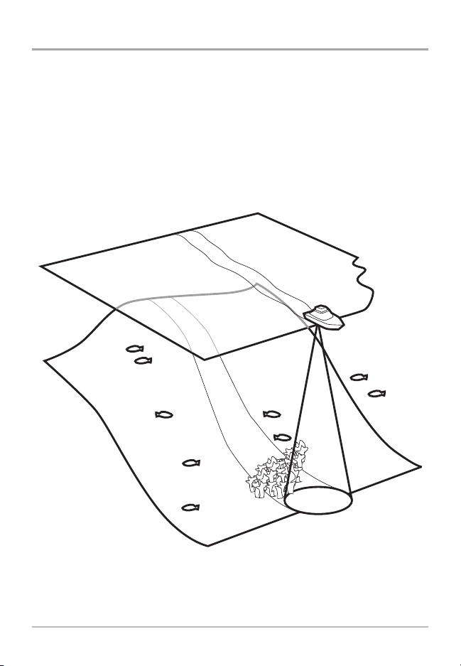
How Sonar Works
Sonar technology is based on sound waves. The HDR 650 Digital Depth Sounder
uses sonar to determine depth directly below the transducer. Your HDR 650
Digital Depth Sounder consists of two components: the HDR 650 sonar unit and
the transducer. The sonar unit contains the transmitter and receiver, as well as
the user controls and display. The transducer is mounted beneath the water
surface and converts electrical energy from the transmitter into mechanical
pulses or sound waves. The transducer also receives the reflected sound waves
and converts them back into electrical signals for display on the sonar unit.
Sonar is very fast. A sound wave can travel from the surface to a depth of 240 ft
(70 m) and back again in less than 1/4 of a second. It is unlikely that your boat
can "outrun" this sonar signal.
1
How Sonar Works
Page 6

Installation Overview
Before you start installation, we encourage you to read these instructions
carefully in order to get the full benefit from your HDR 650 Digital Depth Sounder.
In addition to the hardware included in the installation kit, you will also
need the following supplies:
• powered hand drill and various drill bits, including a 2 1/8" hole saw if your
boat does not have an existing gauge hole
• Phillips-head and flat-head screwdrivers
• ruler or measuring tape
• pen or pencil
• 12 Volt power source (your boat's battery)
• marine-grade silicone sealant (for sealing drilled holes)
NOTE: If you are wiring directly to the boat's battery, you will also need a 1 Amp
fuse and a fuse holder.
Installation
2
Page 7

Installing the HDR 650
You will install your HDR 650 depth sounder first, then your transducer. When
you are done with both of these installation tasks, you should perform a final
installation test before operating your HDR 650. Perform the following high-level
steps by following the instructions in each numbered section to install the depth
sounder:
1. Locating the HRD 650 mounting position
2. Cutting the mounting hole
3. Customizing and assembling the HDR 650
4. Installing the HDR 650
5. Installing the buzzer
6. Connecting to the power supply
7. Installing the transducer: See the transducer installation guide included
with your product.
8. Connecting the transducer cable
9. Testing and finishing the installation
3
Installation
Page 8

1. Locating the HDR 650 Mounting Position
You must select an appropriate mounting location for the HDR 650. Consider
different positions on the console or deck of the boat, and note the following:
• The cables for the transducer and power must reach the mounting location.
Extension cables are available.
• The mounting surface should be visible to the boat operator and adequately
supported to protect the HDR 650 from excessive wave shock and vibration.
• Allow at least 2" clearance at the back, sides, and top of the unit for
connection, air flow, and ease of installation and removal.
Choosing Mounting Hole Location
2. Cutting the Mounting Hole
Once you have selected your mounting location, perform the following steps:
1. Mark the desired mounting location, then drill a pilot hole.
2. Drill a 2 1/8" diameter hole using a hole saw and hand drill. This is a
standard hole saw readily availablefor rental or purchase. If you prefer, any
marine service shop can perform this task.
Installation
4
Page 9

3. Customizing and Assembling the HDR 650
Your HDR 650 includes a variety of face plates and trim rings so you can
customize the appearance.
1. Select one face plate and one trim ring.
2. Peel off the protective backing from the face plate. Be careful not to let the
adhesive touch anything prematurely.
CAUTION: In order to provide a lasting, waterproof bond, the face plate adhesive
is extremely sticky, and you will NOT be able to re-position it once you have stuck
it onto the face of the HDR 650.
3. Carefully line up the face plate with the face of the HDR 650. Press the face
plate into place so that all keys are accessible and the display is visible (see
illustration).
4. Align the inside tabs of the trim ring with the HDR 650 tabs, and snap the
trim ring onto the front of the HDR 650 (see illustration).
HDR 650
Face Plate
Trim Ring
Tabs
5
Installation
Page 10

4. Installing the HDR 650
After the mounting hole has been cut (see section 2), continue the installation as
follows:
1. Remove the gasket and collar by unscrewing them from the HDR.
2. Insert the HDR through the front hole of the dashboard.
3. From the rear of the dashboard, install the gasket and collar onto the HDR.
Attaching the Gasket and Collar
Collar
Gasket
Dashboard View
4. Hand-tighten the collar until the
HDR is securely mounted in the
dashboard. Make sure that the
face of the HDR stays oriented
upright.
Installation
HDR 650 Control Head
Hand-tightening the Collar
6
Page 11

5. Installing the Buzzer
1. Secure the buzzer to a nearby wire bundle
using the cable ties (included).
Securing the Buzzer
Buzzer
6. Connecting to the Power Supply
Use the following information to connect your HDR 650 to an appropriate power
supply:
• If your boat has an electrical system, there is probably a fuse panel in the
console area that can be used to attach the HDR 650 power cable.
• If a fuse terminal is available, use crimp-on type electrical connectors (not
included) that match the terminal on the fuse panel. Attach the black wire
to ground and the red wire to 12 VDC power. You must use a 1-Amp fuse in
the connection.
• 36" of powercable is included; you may shorten or lengthenthis cable using
18-gauge, multi-strand copper wire.
7
Installation
Page 12

GROUNDGROUND
POSITIVEPOSITIVE
Inline Fuse Holder
CAUTION: Some boats have 24 or 36 Volt electrical systems. Make sure that your
HDR 650 is connected to a 12 VDC power supply. Use a voltage conditioner for
variable inputs.
NOTE: Humminbird is not responsible for over-voltage or over-current failures. The
control head must have adequate protection through the proper selection and
installation of a 1 amp fuse.
1a. If a fuse terminal is available, use crimp-on type electrical connectors
(not included) that match the terminal on the fuse panel. Attach the
black wire to ground (-), and the red wire to positive (+) 12 VDC power.
Install a 1 amp fuse (not included) for protection of the unit.
Humminbird is not responsible for over-voltage of over-current failures.
or...
1b. If you need to wire the HDR 650 directly to a battery, obtain and install
an inline fuse holder and a 1 amp fuse (not included) for the protection
of the unit. Humminbird is not responsible for overvoltage or
overcurrent failures.
7. Installing the Transducer
Proceed to the transducer installation guide (included with your product) to install
the transducer.
Before you start installation, we encourage you to read the instructions carefully
so that you may understand the installation requirements.
Installation
8
Page 13

8. Connecting the Transducer Cable
1. Plug the transducer cable into the matching connector cable on the HDR.
NOTE: The connector is keyed to prevent reverse installation, so be careful not
to force the plug into the connector the wrong way.
9. Testing and Finishing the Installation
Once you have installed both the HDR 650 and the transom transducer, and have
routed all the cables, you must perform a final test before locking the transducer
in place.
1. Turn on the power source to power on the HDR. If the unit does not power
up, make sure the connector is secure and that power is available.
2. The HDR will start normal operation. If the digital depth readout displays
on the screen, the unit is working properly.
3. Test and Finalize the Installation: Follow the instructions in the
Transducer Installation Guide: Testing and Finishing the Installation.
You will test the transducer at high speeds, make adjustments, and secure
the installation.
9
Installation
Page 14

Operating the HDR 650
Your HDR 650 Digital Depth Sounder sends a sound wave signal and determines
distance by measuring the time between the transmissionof the soundwaveand
when the sound wave is reflected off of an object. As your HDR 650 transducer
receives sonar signals, it converts them to a digital depth that is shown on the
HDR 650 display. The depth reading is continuously updated as you travel across
the water. The liquid crystal display (LCD) offers sharp viewing, even in bright,
direct sunlight, and is continuously lit for nighttime operation.
NOTE: Actual depth capability depends on such factors as bottom hardness, water
conditions, and transducer installation. Units will typically read to deeper depths in
freshwater than in saltwater.
The HDR 650 Control Head
The HDR 650 uses a backlit display, together with a 3-button keypad, to control
all user functions. The illustration below shows an example of the digital display.
HDR 650
Depth
Alarm Icon
(flashes to
indicate
alert)
Operations
Units
Shallow Alarm
Icon
(indicates
Shallow Alarm
is set)
DOWN arrow key MENU key UP arrow key
10
Page 15

Power On/Off
The power is controlled by the power source connected to the HDR 650. When
the power source is turned on, the HDR 650 is powered on. When the power
source is turned off, the HDR 650 is powered off.
Key Functions Overview
1. Select a Function: Press the MENU key repeatedly until you reach the
appropriate menu.
2. Adjust the Setting: Press the UP or DOWN arrow key to adjust the
setting. Press and hold either key to scroll through the range of settings
quickly.
3. Save: After your selection is made, wait 5 seconds for the unit to return
to normal operation. Your settings are saved automatically even after the
unit is powered off.
11
Operations
Page 16

Units
The Units control function selects the units of measure for depth readout
and alarm functions. You can set the units of measurement to feet, meters,
or fathoms.
Set
Units
1. Press the MENU key until the Units icon is displayed and flashing on the
screen.
2. Press the UP or DOWN arrow key to scroll through the available units.
(FT = feet, M = meters, FA = fathoms).
3. After your selection is made, wait 5 seconds for the unit to return to normal
operation. Your settings are saved automatically.
Operations
12
Page 17

Shallow Alarm
The Shallow Alarm will sound when the measured depth is less than the setting.
1. Press the MENU key until the Shallow Alarm icon is displayed and flashing
on the screen.
Set
Shallow Alarm Icon
2. Press the UP or DOWN arrow key to change the setting.
(Off, 1 - 20 feet, .1 - 6 meters, or .1 - 3.2 fathoms; Default = Off)
NOTE: The maximum Shallow Alarm setting cannot meet or exceed the current
Deep Alarm setting (see the Deep Alarm section).
3. After your selection is made, wait 5 seconds for the unit to return to normal
operation. Your settings are saved automatically, and the Shallow icon will
be visible on the display.
4. Alarm: If the depth of the water is less than the saved setting, the alarm
will sound and the alarm icon will flash on the screen.
Mute: Press any key to mute the alarm.
Adjust: Press the MENU key and follow the instructions in step 2 to adjust
the alarm setting.
13
Operations
Page 18

Deep Alarm
The Deep Alarm will sound when the measured depth is greater than the setting.
1. Press the MENU key until the Deep Alarm icon is displayedand flashing on
the screen.
Set
Deep Alarm Icon
2. Press the UP or DOWN arrow key to change the setting. (Off, 20 - 99 feet,
6 - 30 meters, or 3.3 - 16 fathoms; Default = Off)
NOTE: The minimum Deep Alarm setting cannot meet or drop below the
current Shallow Alarm setting (see the Shallow Alarm section).
3. After your selection is made, wait 5 seconds for the unit to return to normal
operation. Your settings are saved automatically, and the Deep icon will be
visible on the display.
4. Alarm: If the depth of the water is greater than the saved setting, the
alarm will sound and the alarm icon will flash on the screen.
Mute: Press any key to mute the alarm.
Adjust: Press the MENU key and follow the instructions in step 2 to adjust
the alarm setting.
Operations
14
Page 19

Set Offset (waterline or keel)
The Set Offset function adjusts the digital depth readout to display depth
readings from the waterline or the keel (lowest point of the boat) instead of the
transducer location.
1. Choose to measure the depth from the keel or waterline.
Keel: Measure the vertical distance between the face of the transducer
and the keel of the boat.
Waterline: Measure the vertical distance between the face of the
transducer and the waterline of the boat.
2. Press the MENU key until Set Offset is displayed and flashingon the screen.
3. Enter your chosen offset measurement as follows:
Keel Offset
(Set a Negative Number)
Keel: Press the DOWN arrow key to enter the
measurement from step 1 as a negative (-)
number. (-1 to -10 feet, -.1 to -3.0 meters, or
-.1 to -1.6 fathoms; Default = 0)
Negative
Number
Waterline Offset
(Set a Positive Number)
Offset
Icon
Waterline: Press the UP arrow key to enter the
measurement from step 1 as a positive (+)
number. (+1 to +10 feet, +.1 to +3.0 meters, or
+.1 to +1.6 fathoms; Default = 0)
Postive
Number
Offset
Icon
4. After your selection is made, wait 5 seconds for the unit to returnto normal
operation. Your settings are saved automatically, and the offseticon will be
visible on the display.
15
Operations
Page 20

Maintenance
To keep both your HDR 650 and your transducer working properly, perform the
following maintenance tasks as needed.
HDR 650 Maintenance
If your HDR 650 unit comes into contact with salt spray, simply wipe the affected
surfaces with a cloth dampened in fresh water. Do not use a chemical glass
cleaner on the lens, as chemicals in the solution may cause cracking in the lens.
When cleaning the LCD protective lens, use a chamois and non-abrasive, mild
cleaner. Do not wipe while dirt or grease is on the lens. Be careful to avoid
scratching the lens.
WARNING: Never leave your HDR 650 in a closed car or trunk; the extremely high
temperatures generated in hot weather can damage the electronics.
Transducer Maintenance
If your boat remains in the water for long periods of time, algae and other marine
growth can reducethe effectivenessof the transducer. Periodically clean the face
of the transducer with hot water. Pivoting the transducer up in the bracket may
allow better access for inspection or cleaning.
If your boat remains out of the water for a long period of time, it may take some
time to wet the transducer after it is returned to the water. Small air bubbles can
cling to the surface of the transducer and interfere with proper operation. These
bubbles will dissipate with time, or you may wipe the face of the transducer with
your fingers after the transducer is in the water.
Maintenance
16
Page 21

Troubleshooting
Before contacting Humminbird Customer Service, please read the following
section. Taking the time to review these troubleshooting guidelines may allow
you to solve a performance problem yourself, and therefore avoid sending your
unit back for repair.
NOTE: Do not attempt to repairthe HDR 650 yourself, as there are no user-serviceable
parts inside, and special tools and techniques are required for reassembly in order to
maintain the waterproof integrityof the housing. Repairs should be performed only by
authorized Humminbird technicians.
HDR 650 Doesn't Power Up
If your HDR 650 doesn't power up, refer to the Installation section, and make
sure that:
• the power cable is properly connected to the HDR 650;
• the power cable is wired correctly, with red to positive battery terminal and
black to negative terminal or ground;
• the fuse is operational; a fuse can often appear to be good when in fact it
is not; check the fuse with a tester or replace it with a known good fuse;
• if the unit is wired through a fuse panel, make sure that the panel is
powered, as accessory fuse panels are often controlled by a separate
switch, or even the ignition switch of the boat;
• the battery voltage of the power connector is between 10 and 20 VDC.
Correct any known problems, including removing corrosion from the battery
terminals or wiring, or actually replacing the battery if necessary.
17
Troubleshooting
Page 22

No Bottom Reading on the Display
If there is no bottom reading visible on the display, there are a number of possible
causes for this condition, including:
• if the loss of bottom information occurs only at high boat speeds, then a
transducer adjustment may be needed (refer to the Transducer Installation
Guide);
• check the transducer cable connection on the back of the HDR 650 and
make sure that the cable to the transducer has not been cut or pinched, as
even a small abrasion in the cable can affect performance significantly.
Correct any known problems, including adjusting the transducer, or actually
replacing the transducer cable if necessary.
No Continuous Depth Display in Very Shallow Water
Losing continuous depth when the boat is in very shallow water is normal,
because the automatic range control cannot lock onto the bottom in depths of
one foot or less.
Screen Fades, Images are not Sharp
If the screen begins to fade, and images are not as sharp as normal, check the
input voltage. The HDR 650 will not operate on input voltages below 10 VDC.
Bottom Reading Disappears During a Hard Turn
Losing the bottom reading temporarily when the boat is executing a hard turn is
normal, as the transducer emerges from the water during such a turn; this
condition should correct itself once the turn is completed.
Troubleshooting
18
Page 23

Specifications
Depth Capability . . . . . . . . . . . . . . . . . . . . . . . . . . . . . . . . . . . .600 ft (180 m)
Power Cable Length . . . . . . . . . . . . . . . . . . . . . . . . . . . . . . . . . . .36" (91 cm)
Operating Frequency . . . . . . . . . . . . . . . . . . . . . . . . . . . . . . . . . . . . .200 kHz
Area of Coverage . . . . . . . . . . . . . . . . . . . . . . . . . .28° @ -10 dB in 200 kHz
Power Output . . . . . . . . . . . . .250 Watts (RMS), 2000 Watts (Peak to Peak)
Current Draw . . . . . . . . . . . . . . . . . . . . . . . . . . . . . . . . . . . . . . . . . . . .60 mA
Power Requirement . . . . . . . . . . . . . . . . . . . . . . . . . . . . . . . . . . .10 - 20 VDC
Display . . . . . . . . . . . . . . . . . . . . . . . . . . . . . . . . . .Liquid Crystal Diode (LCD)
Mounting . . . . . . . . . . . . . . . . . . . . . . . . . . . . . . . . . . . . .In-Dash 2 1/8" hole
Unit Housing . . . . . . . . . . . . . . . . . . . . . . . . . . . . . . . . . .High-Impact Plastic
Transducer . . . . . . . . . . . . . . . . . . . . . . . . . . . . . . . . . . . . . . . . . . . .XNT 9 28
Transducer Cable Length . . . . . . . . . . . . . . . . . . . . . . . . . . . . . . . .20 ft (6 m)
IPX Rating . . . . . . . . . . . . . . . . . . .IPX7 Waterproof/Submersible @ 1 m for
30 minutes and dust tight
NOTE: Humminbird verifies maximum stated depth in saltwater conditions, but
actual depth performance may vary due to transducer installation, water type,
thermal layers, bottom composition and slope.
NOTE: Product specifications and features are subject to change without notice.
19
Specifications
Page 24

ENVIRONMENTAL COMPLIANCE STATEMENT: It is the intention of Johnson
Outdoors Marine Electronics, Inc. to be a responsible corporate citizen, operating in
compliance with known and applicable environmental regulations, and a good
neighbor in the communities where we make or sell our products.
WEEE DIRECTIVE: EU Directive 2002/96/EC “Waste of Electrical and Electronic
Equipment Directive (WEEE)” impacts most distributors, sellers, and manufacturers
of consumer electronics in the European Union. The WEEE Directive requires the
producer of consumer electronics to take responsibility for the management of
waste from their products to achieve environmentally responsible disposal during
the product life cycle.
WEEE compliance may not be required in your location for electrical & electronic
equipment (EEE), nor may it be required for EEE designed and intended as fixed or
temporary installation in transportation vehicles such as automobiles, aircraft, and
boats. In some European Union member states, these vehicles are considered
outside of the scope of the Directive, and EEE for those applications can be
considered excluded from the WEEE Directive requirement.
This symbol (WEEE wheelie bin) on product indicates the product must not
be disposed of with other household refuse. It must be disposed of and
collected for recycling and recovery of waste EEE. Johnson Outdoors
Marine Electronics, Inc. will mark all EEE products in accordance with the
WEEE Directive. It is our goal to comply in the collection, treatment, recovery, and
environmentally sound disposal of those products; however, these requirements do
vary within European Union member states. For more information about where you
should dispose of your waste equipment for recycling and recovery and/or your
European Union member state requirements, please contact your dealer or
distributor from which your product was purchased.
ROHS STATEMENT: Product designed and intended as a fixed installation or part
of a system in a vessel may be considered beyond the scope of Directive
2002/95/EC of the European Parliament and of the Council of 27 January 2003 on
the restriction of the use of certain hazardous substances in electrical and
electronic equipment.
Specifications
20
Page 25

Notes
21
Page 26

Contact Humminbird
Contact Humminbird Customer Service in any of the following ways:
Web site:
humminbird.com
E-mail:
service@humminbird.com
Telephone:
1-800-633-1468
Direct Shipping:
Humminbird
Service Department
678 Humminbird Lane
Eufaula, AL 36027 USA
Hours of Operation:
Monday - Friday
8:00 a.m. to 4:30 p.m. (Central Standard Time)
22
 Loading...