

Humminbird 345C, 345C DI User Manual
345c and 345c DI
345c and 345c DI
Operations Manual
Operations Manual
531955-1EN_A

Thank You!
Thank you for choosing Humminbird®, America’s #1 name in fishfinders.
Humminbird® has built its reputation by designing and manufacturing
top-quality, thoroughly reliable marine equipment. Your Humminbird® is
designed for trouble-free use in even the harshest marine environment. In
the unlikely event that your Humminbird® does require repairs, we offer an
exclusive Service Policy - free of charge during the first year after purchase,
and available at a reasonable rate after the one-year period. For complete
details, see the separate warranty card included with your unit. We
encourage you to read this operations manual carefully in order to get full
benefit from all the features and applications of your Humminbird® product.
To contact our Customer Resource Center, call 1-800-633-1468 or visit our
Web site at humminbird.com.
WARNING! This device should not be used as a navigational aid to prevent collision,
grounding, boat damage, or personal injury. When the boat is moving, water depth may
change too quickly to allow time for you to react. Always operate the boat at very slow
speeds if you suspect shallow water or submerged objects.
WARNING! Disassembly and repair of this electronic unit should only be performed by
authorized service personnel. Any modification of the serial numberor attempt to repair the
original equipment or accessories by unauthorized individuals will void the warranty.
WARNING! This product contains chemicals known to the State of California to cause
cancer and/or reproductive harm.
WARNING! Do not travelathigh speed with the unit cover installed.Remove the unit cover
before traveling at speeds above 20 mph.
NOTE: Some features discussed in this manual require a separate purchase, and
some features are only available on international models. Everyeffort has been made
to clearly identify those features. Please read the manual carefully in order to
understand the full capabilities of your model.
ENVIRONMENTAL COMPLIANCE STATEMENT: It is the intentionof Humminbird® to be
a responsible corporate citizen, operating in compliance with known and applicable
environmental regulations, and a good neighbor in the communities where we make or sell
our products.
WEEE DIRECTIVE: EU Directive 2002/96/EC“Waste of Electrical and ElectronicEquipment
Directive (WEEE)” impacts most distributors, sellers, and manufacturers of consumer
electronics in the European Union. The WEEE Directive requires the producer of consumer
electronics to take responsibility for the management of waste from their products to
achieve environmentally responsible disposal during the product life cycle.

WEEE compliance may not be requiredin yourlocation for electrical & electronic equipment
(EEE), nor may it be required for EEE designed and intended as fixed or temporary
installation in transportation vehicles such as automobiles, aircraft, and boats. In some
European Union member states, these vehicles are considered outside of the scope of the
Directive, and EEE for those applications can be considered excluded from the WEEE
Directive requirement.
This symbol (WEEE wheelie bin) on product indicates the product must not be
disposed of with other household refuse. It must be disposed of and collected for
recycling and recovery of waste EEE. Humminbird® will mark all EEE products in
accordance with the WEEE Directive. It is our goal to comply in the collection,
treatment, recovery, and environmentally sound disposal of those products; however, these
requirements do vary within European Union member states. For more information about
where you should dispose of your waste equipment for recycling and recovery and/or your
European Union member state requirements, please contact your dealer or distributor from
which your product was purchased.
ROHS STATEMENT: Product designed and intended as a fixed installation or part of a
system in a vessel may be considered beyond the scope of Directive 2002/95/EC of the
European Parliament and of the Council of 27 January 2003 on the restriction of the use of
certain hazardous substances in electrical and electronic equipment.
ATTENTION INTERNATIONAL CUSTOMERS: Products sold in the U.S. are not
intended for use in the international market. Humminbird® international units provide
international features and are designed to meet country and regional regulations.
Languages, maps, time zones, units of measurement, and warranty are examples of
features that are customized for Humminbird® international units purchased through
our authorized international distributors.
To obtain a list of authorized international distributors, please visit our Web site at
humminbird.com or contact our Customer Resource Center at (334) 687-6613.
300 Series™, Down Imaging™, DualBeam PLUS™, Fish ID+™, Humminbird®, RTS™, RTS
Window™, Structure ID®, SwitchFire™, WhiteLine™, and X-Press™ Menu are trademarked by
or registered trademarks of Humminbird®.
Baekmuk Batang, Baekmuk Dotum, Baekmuk Gulim, and Baekmuk Headline are registered
trademarks owned by Kim Jeong-Hwan.
© 2011 Humminbird®, Eufaula AL, USA. All rights reserved.

Table of Contents
Power On 1
How Sonar Works 2
DualBeam PLUS™ Sonar (DualBeam PLUS™ models only [345c])................................ 4
Down Imaging™ Sonar
Dual Beam Ice Transducer
What’s on the Sonar Display 7
Understanding the Sonar Display .......................................................................... 9
Real Time Sonar (RTS™) Window .......................................................................... 9
SwitchFire™ .......................................................................................................... 10
Freeze Frame and Active Cursor .......................................................................... 10
Instant Image Update............................................................................................ 10
Bottom Presentation.............................................................................................. 11
What’s on the Down Imaging™ Display
(Down Imaging™ models only [345c DI])
Understanding the Down Imaging™ Display........................................................15
Interpreting the Display..........................................................................................15
Down Imaging™ Sensitivity ..................................................................................16
Freeze Frame and Active Cursor ............................................................................16
(Down Imaging™ models only [345c DI]) ................................ 5
(optional-purchase XI 9 20 Ice Transducer only) .................. 6
13
Views 17
Sonar View ............................................................................................................ 19
Sonar Zoom View .................................................................................................. 20
Split Sonar View .................................................................................................... 21
Big Digits View ...................................................................................................... 22
Down Imaging™ View
Circular Flasher View ............................................................................................ 24
Down Imaging™/Sonar Combo View
(Down Imaging™ models only [345c DI])................................ 23
(Down Imaging™ models only [345c DI]) ........ 29
i

Table of Contents
What’s on the 300 Series™ Control Head 30
Key Functions 31
POWER/LIGHT Key .............................................................................................. 31
VIEW Key .............................................................................................................. 31
MENU Key ............................................................................................................ 32
4-WAY Cursor Control Key .................................................................................. 32
EXIT Key ................................................................................................................ 33
The Menu System 34
Start-Up Options Menu 35
Normal.................................................................................................................... 35
Simulator .............................................................................................................. 36
System Status ...................................................................................................... 36
Self Test.................................................................................................................. 37
Accessory Test........................................................................................................ 37
X-Press™ Menu 38
Main Menu 39
Quick Tips for the Main Menu
Note for all Menu Settings .......................................................................................... 40
User Mode (Normal or Advanced) .............................................................................. 41
.................................................................................. 40
Sonar X-Press™ Menu
Sensitivity .............................................................................................................. 44
Upper Range
(Advanced: Sonar, Split Sonar, Circular Flasher, and Big Digits Views only) ................ 45
Lower Range ........................................................................................................ 45
Chart Speed .......................................................................................................... 46
(Sonar Views only)
ii
43

Table of Contents
Zoom Level (Sonar Zoom View only) .......................................................................... 46
Bottom Lock
Bottom Range (Sonar Zoom View only when Bottom Lock is On) .................................. 47
(Sonar Zoom View only) ........................................................................ 46
Down Imaging™ X-Press™ Menu
Imaging Sensitivity ................................................................................................ 49
Upper Range
Lower Range .......................................................................................................... 50
Chart Speed............................................................................................................ 50
Imaging Colors ...................................................................................................... 50
Flasher X-Press™ Menu
Sensitivity .............................................................................................................. 52
Upper Range
(Advanced: Sonar, Split Sonar, Circular Flasher, and Big Digits Views only) ................ 52
Lower Range .......................................................................................................... 53
Color Palette
Zoom Level
(Advanced, Down Imaging™ Views only) .............................................. 49
(Circular Flasher View only)
(Circular Flasher, Ice Fishing Mode only) ................................................ 53
(Circular Flasher View, Ice Fishing Mode only) .......................................... 54
(Down Imaging™ Views only [345c DI])
48
51
Alarms Menu Tab 55
Depth Alarm .......................................................................................................... 56
Fish ID Alarm.......................................................................................................... 56
Low Battery Alarm ................................................................................................ 56
Temp. Alarm .......................................................................................................... 57
Alarm Tone ............................................................................................................ 57
Sonar Menu Tab 58
Beam Select .......................................................................................................... 59
Imaging Frequency
(Down Imaging™ Views only [345c DI]) ...................................... 60
iii

Table of Contents
Surface Clutter ...................................................................................................... 61
SwitchFire™ .......................................................................................................... 61
Fish ID+™ .............................................................................................................. 62
Fish ID Sensitivity .................................................................................................. 63
Real Time Sonar (RTS™) Window ........................................................................ 63
Sonar Colors
Bottom View .......................................................................................................... 64
Zoom Width .......................................................................................................... 65
83 kHz Sensitivity
455 kHz Sensitivity
Depth Lines
Noise Filter
Max Depth
Water Type
Ice Fishing Mode
Imaging Colors
Setup Menu Tab 69
Units - Depth.......................................................................................................... 70
Units - Temp
Units - Distance
Units - Speed
User Mode ............................................................................................................ 71
Language
Triplog Reset
Restore Defaults .................................................................................................... 71
Select Views
(Sonar View, Sonar Zoom View, and Big Digits View) .............................. 64
(Advanced, DualBeam PLUS™ Sonar only [345c]) .......................... 65
(Advanced, Down Imaging™ only [345c DI]) ................................ 65
(Advanced) .......................................................................................... 66
(Advanced) ............................................................................................ 66
(Advanced) ............................................................................................ 67
(Advanced) ............................................................................................ 67
(Advanced) .................................................................................. 67
(Down Imaging™ Views only [345c DI]).............................................. 68
(International only) .............................................................................. 70
(with Temp/Speed only) .................................................................. 70
(with Temp/Speed only) ...................................................................... 70
(International only).................................................................................... 71
(with Temp/Speed only) ...................................................................... 71
(Advanced).......................................................................................... 72
iv

Table of Contents
Select Readouts (Advanced, Sonar View and Down Imaging™ View only)...................... 72
Depth Offset (Advanced)............................................................................................ 73
Temp. Offset
Digits Format
Speed Calibration
Demonstration.......................................................................................................... 74
Sound Control .......................................................................................................... 74
Troubleshooting 75
Fishfinder Doesn’t Power Up .................................................................................. 75
Fishfinder Defaults to Simulator with a Transducer Attached.............................. 75
Display Problems...................................................................................................... 76
Finding the Cause of Noise .................................................................................... 77
300 Series™ Fishfinder Accessories 78
Specifications 79
Glossary 81
(Advanced) ............................................................................................ 73
(Advanced) ............................................................................................74
(Advanced, with Temp/Speed only).................................................. 74
Contact Humminbird® 85
v

Table of Contents
NOTE: Entries in this Table of Contents which list (International Only) are only
available on products sold outside of the U.S. by our authorized international
distributors. To obtain a list of authorized international distributors, please visit
our Web site at humminbird.com or contact our Customer Resource Center at
(334) 687-6613.
NOTE: Entries in this Table of Contents which list (with Temp/Speed only) require
the purchase of separate accessories. You can visit our Web site at
humminbird.com to order these accessories online or contact our Customer
Resource Center at 1-800-633-1468.
NOTE: Some features discussed in this manual require a separate purchase, and
some features are only available on international models. Every effort has been
made to clearly identify those features. Please read the manual carefully in order
to understand the full capabilities of your model.
vi

Power On
Follow the instructions below to power on your Humminbird® control head.
345c Title Screen
1. Press the POWER/LIGHT key.
2. When the Title screen is displayed, press the MENU key to access the
Start-Up Options Menu.
3. Use the 4-WAY Cursor Control key to select Normal (if there is a
transducer attached to the control head), or Simulator (if there isn’t a
transducer attached to the control head).
NOTE: See Start-Up Options Menu for more information.
• If a functioning transducer is connected, Normal operation will be
selected automatically at power up, and your Fishfinder can be
used on the water.
• If a transducer is not connected and you wait too long to select a
Start-Up Option, the system will default to whichever menu is
already highlighted.
• In Simulator you can learn how to use your control head and save
settings in advance for later use.
Power On
1
How Sonar Works
Sonar technology is based on sound waves. The 300 Series™ Fishfinder uses
sonar to locate and define structure, bottom contour and composition, as well
as depth directly below the transducer.
Your 300 Series™ Fishfinder sends a sound wave signal and determines
distance by measuring the time between the transmission of the sound wave
and when the sound wave is reflected off of an object; it then uses the reflected
signal to interpret location, size, and composition of an object.
Sonar is very fast. A sound wave can travel from the surface to a depth of
240 ft (70 m) and back again in less than 1/4 of a second. It is unlikely that your
boat can “outrun“ this sonar signal.
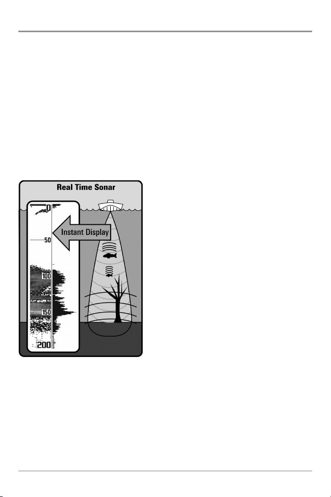
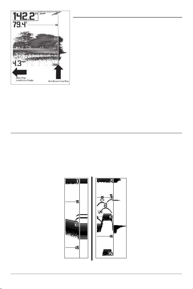
SONAR is an acronym for SOund and
NAvigation Ranging. Sonar uses precision
sound pulses or “pings“ which are emitted
into the water in a teardrop-shaped beam.
The sound pulses “echo“ back from objects
in the water such as the bottom, fish, and
other submerged objects. The returned
echoes are displayed on the LCD screen.
Each time a new echo is received, the old
echoes are moved across the LCD, creating
a scrolling effect.
2
How Sonar Works
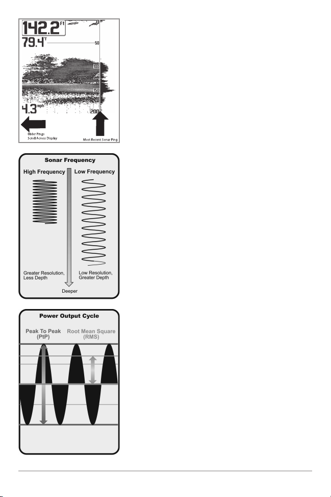
When all the echoes are viewed side by side, an
easy to interpret “graph“ of the bottom, fish, and
structure appears.
The sound pulses are transmitted at various
frequencies depending on the application. Very
high frequencies (455 kHz) are used for greatest
definition but the operating depth is limited. High
frequencies (200 kHz) are commonly used on
consumer sonar and provide a good balance
between depth performance and resolution. Low
frequencies (83 kHz) are typically used to achieve
greater depth capability.
The power output is the amount of energy
generated by the sonar transmitter. It is commonly
measured using two methods:
How Sonar Works
• Root Mean Square (RMS) measures power
output over the entire transmit cycle.
• Peak to Peak measures power output at the
highest points.
The benefits of increased power output are the
ability to detect smaller targets at greater
distances, ability to overcome noise, better high
speed performance and enhanced depth capability.
3
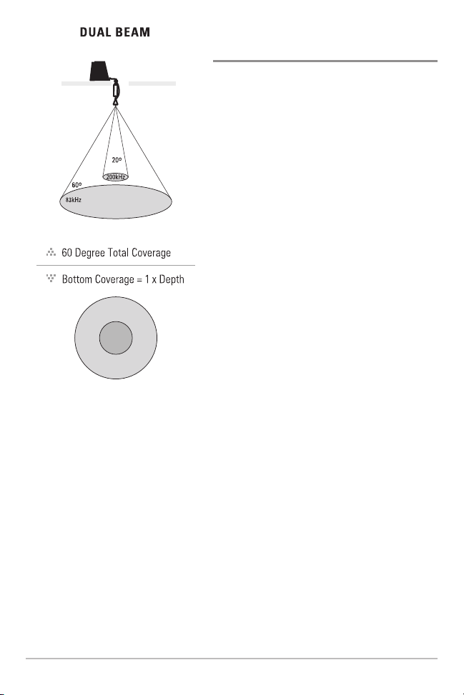
DualBeam PLUS™ Sonar
(DualBeam PLUS™ models only [345c])
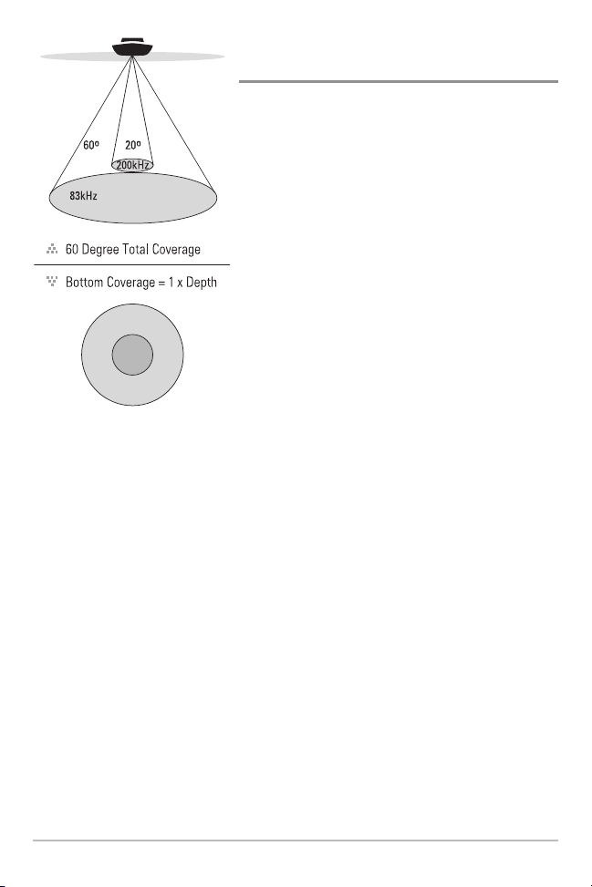
Your 345c Fishfinder uses a 200/83 kHz
DualBeam PLUS™ sonar system with a wide
(60°) area of coverage. DualBeam PLUS™ sonar
has a narrowly focused 20° center beam,
surrounded by a second beam of 60°, expanding
your coverage to an area equal to your depth. In
20 feet of water, the wider beam covers an area
20 feet wide.
DualBeam PLUS™ sonar returns can be blended
together, viewed separately, or compared sideby-side. DualBeam PLUS™ is ideal for a wide
range of conditions - from shallow to very deep
water in both fresh and salt water. Depth
capability is affected by such factors as boat
speed, wave action, bottom hardness, water
conditions, and transducer installation.
4
How Sonar Works
Down Imaging™ Sonar
75 Degree Total Coverage
16°
75°
25°
455kHz
200kHz
455kHz
45°
800kHz
(Down Imaging™ models only [345c DI])
Your 345c DI Fishfinder uses Down
Imaging™ technology. The Down Imaging™
transducer scans the water with razor-thin,
high-definition beams. The beams are wide
(side to side) but very thin front to back.
The Down Imaging™ beams can be operated
at two frequencies: 455 kHz (75°) or 800 kHz
(45°). Select 455 kHz for the best overall
image quality and depth. Select 800 kHz for
the sharpest image. See Sonar Menu Tab:
Imaging Frequency for more information.
The transducer also uses conical beams to
provide data in traditional 2D format (see
What’s on the Sonar Display). Select 455
kHz for a narrowly focused 16° center beam,
or select 200 kHz for a wider 25° beam (see
Sonar Menu Tab: Beam Select).
Depth capability is affected by such factors
as boat speed, wave action, bottom hardness,
water conditions, and transducer installation.
How Sonar Works
5
Ice transducer
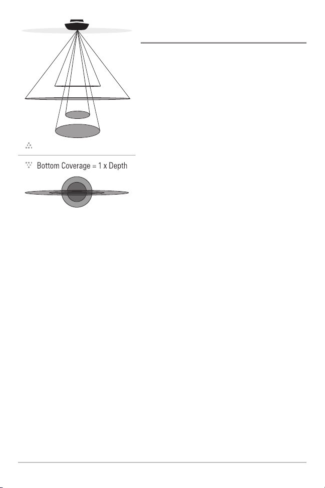
Dual Beam Ice Transducer
(optional-purchase XI 9 20 Ice Transducer only)
Your Fishfinder supports the optionalpurchase XI 9 20 Ice Transducer which
provides selectable dual-frequency sonar
with a wide area of coverage. Selectable
dual-frequency gives you the option of two
beams, and both beams will cover the
bottom and provide high definition. The 20
degree center beam provides the highest
definition, while the 60 degree beam
provides wider coverage. Depth capability
is affected by such factors as bottom
hardness and water conditions. Whether
fishing in shallow to very deep water,
selectable dual-frequency is ideal for a
variety of conditions.
6
How Sonar Works
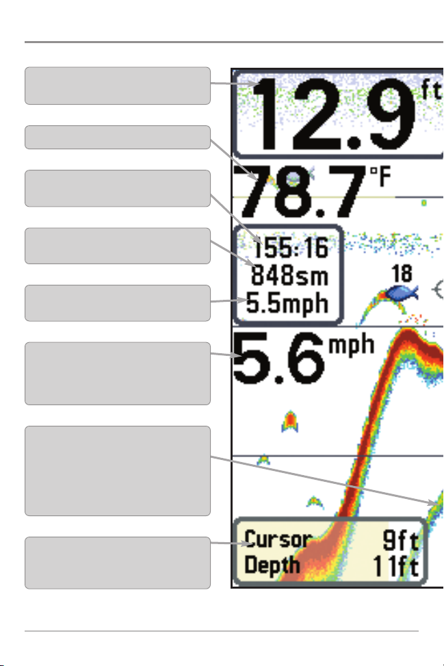
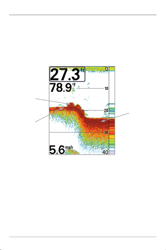
What’s on the Sonar Display
The 300 Series™ Fishfinder can display a variety of useful information about
Depth - Water depth; can be set to alarm when
the water becomes too shallow.
Temperature - Water surface temperature.
Timer - Elapsed time with Temp/Speed
Accessory.
Distance - Distance traveled with Temp/Speed
Accessory.
Average Speed - Average speed reading with
Temp/Speed Accessory.
Speed - If a Temp/Speed accessory is attached,
the Fishfinder can display the speed of the boat
and can keep a Triplog of nautical or statute
miles traveled.
Second Sonar Return - When the sonar signal
bounces between the bottomand the surface of the
water and back again. Use the appearance of the
second return to determine bottom hardness. Hard
bottoms will show astrong secondreturn,while soft
bottoms will show a very weakone ornone atall.
Cursor Dialog Box - Indicates cursor depth on
the display and the depth of the bottom directly
below the cursor.
NOTE: Entries in this view that list (with Temp/Speed) are available if the device is connected to
What’s on the Sonar Display
7
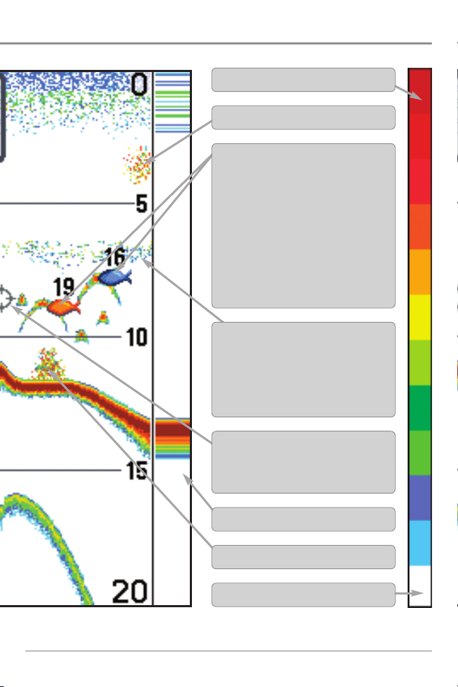
the area under your boat, including the following items:
High Sonar Intensity Return
Bait Ball
Fish - The Fishfinder displays fish as arches
and/or fish icons, and can be set to alarm
when a fish of a certain size is detected.
When a target is detected, a Fish ID+™
symbol appears on the display with the
depth displayed above it. The size of the
symbol indicates the intensity of the sonar
return. The unit will clearly show schools of
Bait Fish as "clouds" of different shapes and
sizes, depending on the number of fish and
boat speed.
Thermoclines - Layers of water with different
temperatures that appear at different depths
and different times of the year. A thermocline
typically appears as a continuous band of
many colors moving across the display at the
same depth.
Cursor - Available in Freeze Frame and can
be positioned in the Sonar View to provide
depth of a sonarreturn andbottomdepth below
the cursor.
the 300 Series™ Fishfinder.
RTS (Real Time Sonar) Window™
Structure - Where fish may be hiding.
Low Sonar Intensity Return
8
What’s on the Sonar Display
Understanding the Sonar Display
It is important to understand the significance of
the display. The display does not show a literal
3-dimensional representation of what is under the
water. Each vertical band of data received by the
control head and plotted on the display represents
something that was detected by a sonar return at
a particular time. As both the boat and the targets
(fish) may be moving, the returns are only showing
a particular segment of time when objects were
detected, not exactly where those objects are in
relation to other objects shown on the display.
The returned sonar echoes are displayed on the screen. As a new echo is
received, the historical data scrolls left across the view.
Real Time Sonar (RTS™) Window
A Real Time Sonar (RTS™) Window appears on the right side of the display in
the Sonar View only. The RTS Window™ updates at the fastest rate possible for
depth conditions and shows only the returns from the bottom, structure, and
fish that are within the transducer beam. The RTS Window™ plots the depth
and intensity of a sonar return (see Sonar Menu Tab: RTS Window™).
The Narrow RTS Window™
indicates the sonar intensity
through the use of colors. Red
indicates a strong return and
blue indicates a weak return.
The depth of the sonar return
is indicated by the vertical
placementofthe return on the
display depth scale.
What’s on the Sonar Display
The Wide RTS Window™
indicates the sonar intensity
through the use of a bar
graph. The length of the
plotted return indicates
whether the return is weak or
strong. The depth of thesonar
return is indicated by the
vertical placement of the
return on the display depth
scale. The Wide RTS
Window™ does not use
grayscale.
9

SwitchFire™
SwitchFire™ controls how the sonar returns are displayed in the Sonar Views.
SwitchFire™ settings are available in the Sonar Menu Tab.
To see the maximum sonar information available within the transducer beam so
more fish arches and better jig tracking are shown, choose Max Mode.
To see less clutter and more fish size accuracy interpreted from the transducer
beam, choose Clear Mode. See Sonar Menu Tab: SwitchFire™ for more
information.
Freeze Frame and Active Cursor
Freeze Frame & Active Cursor - Press any arrow on the 4-WAY Cursor Control key,
and the screen will freeze and a cursor will be displayed. Use the 4-WAY Cursor
Control key to move the cursor over a sonar return, and the depth of the sonar
return will be displayed at the bottom of the screen in the cursor dialog box.
The RTS Window™ continues to update in Freeze Frame. To return to a scrolling
display and exit Freeze Frame, press the EXIT key. Freeze Frame is available in the
Sonar, Split Sonar, and Sonar Zoom Views.
Instant Image Update
Instant Image Update - You can change a variety of sonar menu settings (such
as Sensitivity or Upper Range), and the adjustments will be shown instantly on
the screen.
10
What’s on the Sonar Display
Bottom Presentation
As the boat moves, the unit charts the changes in depth on the display to create
a profile of the Bottom Contour. The type of bottom can be determined from
the return charted on the display. A Hard Bottom such as compacted sediment
or flat rock appears as a thinner line across the display. A Soft Bottom such as
mud or sand appears as a thicker line across the display. Rocky Bottoms have
a broken, random appearance.
Bottom Contour Profile with RTS Window™
Rocky Bottom
Soft Bottom
Hard Bottom
The sonar returns from the bottom, structure, and fish can be represented as
WhiteLine™ or Structure ID®. See Sonar Menu Tab: Bottom View to set the
bottom view.
What’s on the Sonar Display
11
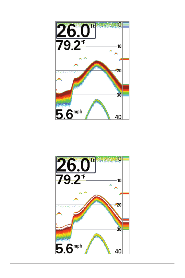
Structure ID® represents weak returns in blue and strong returns in red.
WhiteLine™ highlights the strongest sonar returns in white, resulting in a
distinctive outline. This has the benefit of clearly defining the bottom on the
display.
12
What’s on the Sonar Display
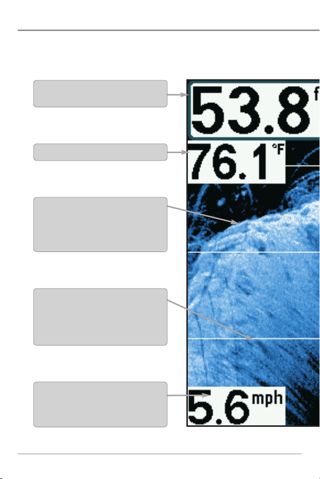
What’s on the Down Imaging™ Display
Down Imaging™ uses its unique transducer and sonar technology to provide
definition profiling beams produce the detailed sonar data that you see on the
can interpret the structure and bottom contour, including the following items:
Depth - (water depth) can be set to alarm when
the water becomes too shallow.
Temperature - Water surface temperature.
Bottom Return-Use theappearanceof thebottom
return to determine bottom hardness. Rock and
gravel provide a clearer sonar return than mud
and sand because hard objects reflect sonar
better than soft objects.
Topography Changes - The light part of the
display shows where the beam is hitting hard
bottom or rising terrain. The dark part of the
display indicates soft bottom (sand, mud) or
descending terrain.
Speed-IfaTemp/Speed accessory is connected,
the Fishfinder can display the speed of the boat
and can keep a Triplog of nautical or statute
miles traveled.
NOTE: Entries in this view that list (with Temp/Speed) are available if the accessory is
What’s on the Down Imaging™ Display
13
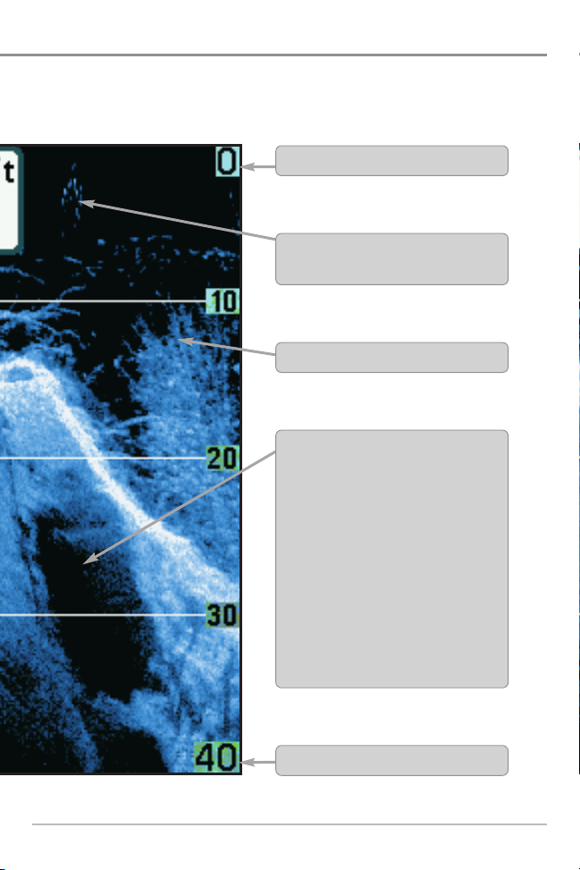
(Down Imaging™ models only [345c DI])
information about the area directly below your boat. The razor-thin, highdisplay. Down Imaging™ reveals a variety of recognizable features so that you
Upper Range
Clouded Area may indicate a bait ball and
White Streaks may indicate fish.
Structure
Shadows- Result from a lack of reflected
sonar from a particular area and can be as
valuable for interpretation than the sonar
reflected by the object itself. Use shadows to
help you see the image in 3 dimensions,
oriented in space. You can gain insight into
the actual shape of an object, or the depth
to which it has sunk into the bottom,
through shadows on the display. Objects
standing on the bottom cast a sonar
shadow. The longer the shadow, the taller
the object. Fish also cast shadows. You can
use the shadow to interpret how close the
fish is to the bottom.
connected to the 300 Series™ Fishfinder.
Lower Range
14
What’s on the Down Imaging™ Display

Understanding the Down Imaging™ Display
The images you see on the Down Imaging™
display are produced using sonar technology. Each
time the unit pings, a strip of data representing all
the echoes received by the transducer are put
together on the display to form the image that you
see. Like traditional 2D Sonar, the sonar history
scrolls left across the screen.
Interpreting the Display
Down Imaging™ beams “illuminate” the bottom contour, structure, and fish.
The beams are wide (side to side) but very thin front to back.
Use the light and dark parts of the display to interpret the objects under your
boat as follows:
• Dark shades represent soft returns (mud, sand) or descending terrain.
• Light shades represent denser terrain (timber, rocks) or rising terrain. A
very hard bottom may appear as white on the display.
• White Streaks or Clouds may represent fish on the display.
• Shadows are not caused by light but by the lack of a sonar return.
Objects standing on the bottom cause a sonar shadow to appear on the
display. The longer the shadow, the taller the object. Fish may also cast
shadows. You can use the shadow to interpret where the fish or object
is located in relation to the bottom.
What’s on the Down Imaging™ Display
15

Down Imaging™ Sensitivity
Use Imaging Sensitivity to control how the sonar returns appear on the
display. Increase the sensitivity to reveal weaker returns that may be of interest,
especially in very clear water or greater depths. Decrease the Imaging
Sensitivity to eliminate the clutter from the display that is sometimes present
in murky or muddy water. See Imaging Sensitivity or Down Imaging™
Sensitivity for more information.
Freeze Frame and Active Cursor
Freeze Frame and Active Cursor - Press any arrow on the 4-WAY Cursor
Control key, and the screen will freeze and a cursor will be displayed. Use the
4-WAY Cursor Control key to move the cursor over a sonar return, and the depth
of the sonar return will be displayed in the cursor dialog box.
16
What’s on the Down Imaging™ Display

Views
The sonar information from your Fishfinder is
displayed on your screen in a variety of easy-to-read
views. There are many views available on your
Fishfinder.
• Default View: When you first power up the 345c control head, Sonar
View will be the default view. When you first power up the 345c DI
control head, Down Imaging™ View will be the default view.
• Cycle: When you press the VIEW key repeatedly, the display cycles
through the available views on your screen. When you press the EXIT
key, the display cycles through the available views in reverse order.
• Customize: You can display or hide any view to suit your fishing
preferences. See the following pages for more information about each
View.
NOTE: When you change any menu settingsthat affect the sonar, the view will update
immediately. You don't have to exit the menu to apply the change to the screen.
Views
17

To customize your view rotation:
You can choose which views are hidden or visible in your view rotation.
1. Press the MENU key twice to access the tabbed Main Menu, then
press the RIGHT Cursor key until the Setup tab is selected.
2. Press the DOWN Cursor key to highlight Select Views, and press the
RIGHT Cursor key to access the Select Views submenu.
NOTE: If the Select Views option does not appear under the Setup tab, change the
User Mode to Advanced.
3. Press the UP or DOWN Cursor keys to select a View.
4. Press the LEFT or RIGHT Cursor keys to change the status of the view
from Hidden to Visible or vice versa.
To change the Digital Readouts:
Each view displays digital readout information (such as speed or time), which
varies with the view selected and the accessory attached. The digital readouts
on the Sonar View can be customized. See Setup Menu Tab: Select Readouts
for more information.
1. Press the MENU key twice to access the tabbed Main Menu, then
press the RIGHT Cursor key until the Setup tab is selected.
2. Press the DOWN key to highlight Select Readouts, and press the RIGHT
Cursor key to access the Select Readouts submenu.
NOTE: If the Select Readoutsoption does not appear under the Setup Tab, changethe
User Mode to Advanced.
3. Press the UP or DOWN Cursor keys to select a Readout position, then
press the RIGHT or LEFT Cursor keys to choose what will be displayed in
that position. To hide the data window, select Off.
18
Views
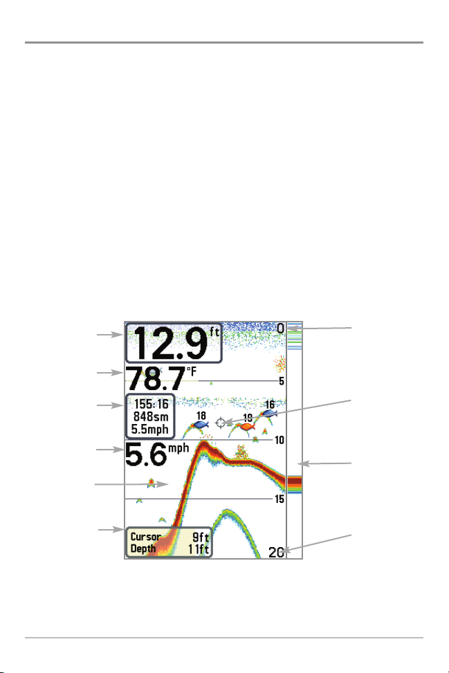
Sonar View
Sonar View presents a historical log of sonar returns. The most recent sonar
returns are charted on the right side of the display. As new information is
received, the historical information scrolls left across the display.
• Upper and Lower Depth Range numbers indicate the distance from the
surface of the water to a depth range sufficient to show the bottom.
• Depth is automatically selected to keep the bottom visible on the display,
although you can adjust it manually as well (see Sonar X-Press™ Menu).
• Digital Readouts shown on the display will change based on the Select
Readouts settings or the optional-purchase accessories attached (see
Setup Menu Tab: Select Readouts).
• Freeze Frame - Use the 4-WAY Cursor Control key to freeze the display and
move the cursor over a sonar return. The depth of the sonar return will be
displayed at the bottom of the screen in the cursor dialog box.
Sonar View
Depth
Temperature
Upper Depth
Range
Triplog
Speed
Sonar History
Window
Cursor
Dialog Box
NOTE: If the Depth number is flashing, it means that the unit is having trouble locating
the bottom. This usually happens if the water is too deep, the transducer is out of the
water, the boat is moving too fast, or for any other reason that the unit can’t accurately
receive continuous data.
Views
19
Cursor
RTS Window™
Lower Depth
Range
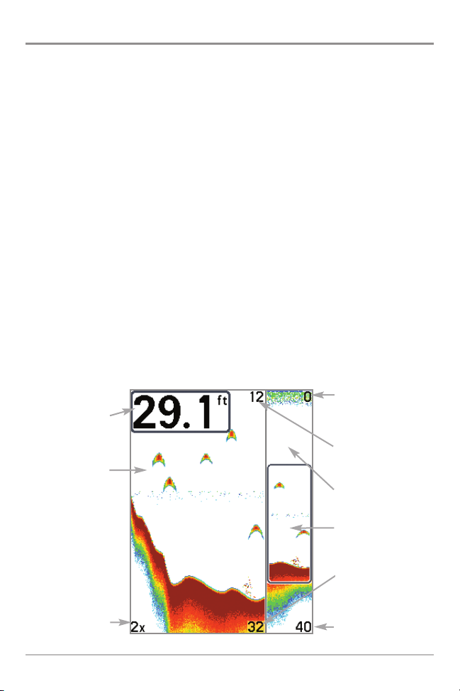
Sonar Zoom View
Sonar Zoom View provides a magnified view of the bottom and structure. The
Sonar Zoom View makes it easier to see separate sonar returns that would
usually be displayed close together, such as those caused by fish suspended
close to the bottom or within structure.
• The Zoom Level, or magnification, is displayed in the lower left corner
of the display. Press the MENU key once to access the Sonar X-Press™
Menu and use Zoom Level to adjust the zoom settings.
• The Zoomed View is displayed on the left side of the screen. As the
depth changes, the zoomed view updates automatically.
• The Full Range View is displayed on the right side of the screen. The
Full Range View includes the Zoom Preview Box, which shows where
the zoomed view is in relation to the full range view.
• The Upper and Lower Depth Range numbers indicate the high and low
range of the water which is being viewed.
• Digital Readouts cannot be customized; therefore, information such as
water temperature and voltage are unavailable in the Sonar Zoom View.
Depth
Zoomed View
Zoom Level
Sonar Zoom View
20
Upper Depth Range,
Full Range View
Upper Depth Range,
Zoom View
Full Range View
Zoom Preview Box
Lower Depth Range,
Zoom View
Lower Depth Range,
Full Range View
Views
 Loading...