

Humanscale V6 Installation Instructions Manual
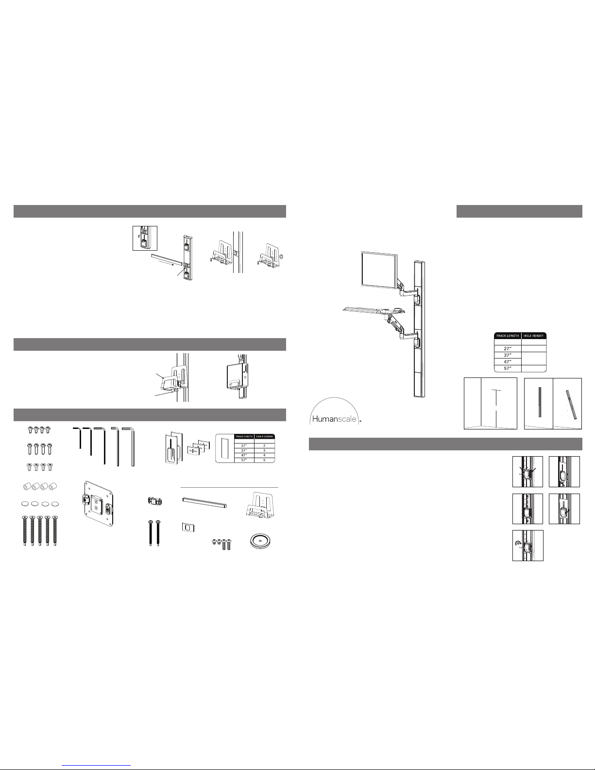
STEP 1: MOUNT TRACK TO WALL
b. Choose the desired hole location for top fastener. Drill hole and install
appropriate fastener.
c. Hold Track against the wall and fasten using the appropriate fastener through
the top pre-drilled hole on track.
d. Use level to ensure Track is perfectly plumb. Mark the other mounting hole
locations.
e. Pre-drill the remaining mounting holes and install appropriate fastener.
f. Fasten Track with appropriate fasteners in the remaining mounting holes. Be
sure to fully tighten so fastener heads do not protrude beyond Track surface.
56”
33”12”
66”
76”
a. For new construction, Track can be mounted to a wall stud or mounting board.
For existing construction, test the wall by drilling a pilot hole to determine what
fasteners are most suitable for installation. Be sure to drill the pilot hole in a spot
that will be covered by the Track.
RECOMMENDATIONS:
For wood – Use 2” #12 (M5.5, 50mm) flat-head wood screws.
For metal – Use 2½” #12 (M5.5, 65mm) flat-head self-tapping screws.
(Provided)
For drywall – Use 3/16” (M5) flat-head toggle bolts.
b ed
66”
STEP 2: ADJUST ARM MOUNT LOCATION
Note: Assuming the Track was mounted to the wall at the recommended height, the Arm Mounts will already be in the
correct ergonomic position for the majority of people for standing use unless a Solo Arm will be used, in which case the
Mount must be adjusted so that the keyboard platform is no higher than 48” when arm is at its highest adjustment range.
Change Position of Arm Mount Location
a. Loosen the Friction Feet with Hex Key C.
b. Slide each Mount up or down the Track to the desired location.
c. Tighten the Feet. You must tighten down the Friction Feet in order to complete installation of the Arm Mount to the
Track. The Arm Mount will not be able to support any weight if it is not tightened down first. Feet must be tightened
down to a torque of 30 in-lbs. [3.4 Nm] to ensure safe operation.
Note: It is recommended to position the Mounts in a detent to allow for the best possible Cover fit in step 10.
Attach the Arm Mount Covers to the Arm Mounts
d. Align one side of the Cover inside of the Track channel.
e. Push in the Crush Rib on that side. By pushing at the top corner at the opposite side, feed the side into the channel,
running fingers down the side and pushing in the Crush Rib at the bottom. Push on the middle of the Cover to
engage the snap feature.
Note: User must install the Arm Mount Covers before the Arms otherwise they cannot be put onto the Track.
a
b
c
d
e
in/lbs.
STEP 11: ATTACH CPU HOLDER OR ACCESSORY RAIL (Optional)
Attach Accessory Rail
a.Screw the V6 rail mount to the V6 Accessory Mount using
the flat head screws and supplied 4mm Allen wrench.
b. Insert the rail through the V6 Mount, measuring both ends
of the rail to ensure it is centered, or positioned as required.
c. Tighten the 2 set screws under the V6 rail mount using the
2mm Allen wrench and snap the front cover back on the mount.
Attach CPU Holder to Accessory Mount
d. Align the CPU Holder with the vertical holes in the center of the
Accessory Mount. Attach with the two M6 Screws provided with the
CPU Holder. Tighten with Hex Key D to secure.
a
b
d
c
Wallmount CPU
Attach CPU Holder to Wall
a. To mount CPU Holder directly to wall, use the provided CPU Wall Mount Spacer and the provided Pan Head Self-Tapping Screws. Please refer to Step 1a on this directions
sheet and read the hardware recommendations, but note that in this instance (for the CPU Holder), you should use the Pan Head Self-Tapping hardware, as opposed to the
Flat Head hardware listed in the Step 1a directions.
b. Drill hole in wall for top through-hole of CPU holder at desired height/location, and install appropriate fastener per the recommendations in Step 1a.
c. Place CPU Wall Mount Spacer between CPU Holder and wall and align their holes. Using the appropriate hardware, fix CPU Holder to wall. Insert Pan Head Self-Tapping
Screw through the top through-hole of CPU Holder and through the CPU Wall Mount Spacer, and into the wall stud or mounting board.
d. Use a level to ensure CPU Holder is level. Mark lower through-hole location on wall (this hole is either of the two recessed through-holes on the CPU Holder).
e. Pre-drill a lower mounting hole in the spot in the wall that you have just marked in Step d, and install appropriate fastener.
f. Fasten CPU Holder with appropriate hardware in lower hole. Be sure to properly tighten screws.
STEP 12: PLACE CPU INTO CPU HOLDER
Loosen other Locking Knob
(a) and place CPU into CPU Holder. Slide Front Bracket
(b) inward so it sits tightly against CPU. TightenLocking Knob to secure.
b
a
V6 INSTALLATION HARDWARE
OPTIONAL COMPONENTS
www.humanscalehealthcare.com
ADDITIONAL HARDWARE REQUIRED
Electric drill
(4) Keyboard Tray Screws
(4) Plastic Spacers
(4) Extended VESA Bracket Screws
VESA Bracket
CPU Wallmount Spacer
(4) 3M Dual Lock Coins
Hex Key E
(5 mm)
Hex Key D
(4 mm)
Hex Key C
(3 mm)
Hex Key B
(2.5 mm)
Hex Key A
(2 mm)
Track Covers
Accessory Mount
(4) Standard VESA Bracket Screws
CPU Holder
Accessory Rail
Accessory Mount Cover
(4) M6 Screws
(2) CPU Wallmounting Screws
(for mounting on metal stud)
(5) Track Mounting Screws
(for mounting on metal stud)
12” 1
*12” tracks only come with one of each track cover
V6
Installation Instructions
HSIV60614

STEP 9: ROUTE CABLES
a b
Note: Cable Openings can
be used if wires need to
exit Track at certain
location
along the Track.
Cables
a. Route cables through the central channel of the Track which runs from
the Top Cap, through the Mounts and any Accessory Mount(s).
b. Route through the Bottom Cap, which allows room for most common
electrical plugs to pass through.
c. The M8 includes a cable management system to keep monitor cables organized and protected. Start by inserting cables into Cable Clip.
d. Route cables across the bottom of the Upper Arm and around to the top of the Lower Arm. Insert cables into groove on top of the Lower Arm. Place Arm Cover onto the
Lower Arm so that the grooves interlock. Slide Arm Cover up until it snaps in place.
Keyboard and Mouse Cables
Monitor Cables
e. The Keyboard includes a cable management system (underneath the Keyboard) to keep Keyboard cables organized and protected. Start by inserting cables into the top of
the Upper Arm.
f. Route cables across the bottom of the Upper Arm and around to the top of the Lower Arm. Insert cables into groove on top of the Lower Arm. Place Arm Cover onto the
Lower Arm so that the grooves interlock. Slide Arm Cover up until it snaps into place.
c fed
The following instructions are based upon the fact that Covers are designed to be installed in a specific orientation in order to minimize openings between Covers. Covers have
arrows on the back of them to indicate the top. A Cover should always go on top of the Cover below it. For this reason, it is recommended to install Covers starting at the
bottom and working up to the top.
Cutting Cable Covers to Size to Accommodate Accessory Mounts and Cable Openings
a. Snap the Cover at the desired location to break the plastic.
b. Using scissors or a blade, cut through the overmold layer between the crack that was created.
STEP 10: ATTACH CABLE COVERS
a b
Attach Cable Covers
c. Align one side of the Cover inside of the Track channel.
d. Pushing at the top corner at the opposite side, feed the side into the channel, running the fingers down the side until the Cover is in place.
c
d
STEP 8: ATTACH ACCESSORY MOUNT TO TRACK (Optional)
a
b
c
d
e
f
g
in/lbs.
Attach Accessory Mount to Track
a. Vertically insert Accessory Mount into the Track cavity. Push down.
b. Rotate the Mount until it is horizontal.
c. The Spring Feet will engage, allowing the user to slide the Mount up or down to the desired position.
d. Using Hex Key C, you must tighten down the Friction Feet in order to complete installation of the
Accessory Mount to the Track. The Accessory Mount will not be able to support any weight if it is not
tightened down first. Feet must be tightened down to a torque of 30 in-lbs. [3.4 Nm] to ensure safe operation.
Note: It is recommended to position the Mounts in a detent to allow for the best possible Cover fit in step 9.
Attach the Accessory Mount Cover to the Accessory Mount
e. Note the up arrow on the back of the Cover to determine which end is up.
f. Align one side of the Cover inside of the Track channel. Push in the Crush Rib on that side.
g. By pushing at the top corner at the opposite side, feed the side into the channel, running
fingers down the side and pushing in the Crush Rib at the bottom.
Note: You must install the Accessory Mount Cover before attaching accessories otherwise the Cover
cannot be put onto the Track.
To remove the Accessory Mount, loosen the Feet (if necessary), push Accessory Mount into Track and
rotate to pull out.
Attach Monitor Arm
a. Remove Set Screws
on Arm Mounts.
b. Drop pin of Monitor Arm
and Keyboard Arm, or Solo
Arm into hole of upper Arm
Mount. Screw in the Set
Screw with Hex Key B.
c. After arms are in place screw
Set Screw back into place.
STEP 3: ATTACH MONITOR AND KEYBOARD ARMS OR SOLO ARM
a
x2
Example of Standard Arms
Example of Solo Arm
STEP 4: ATTACH KEYBOARD TRAY TO KEYBOARD ARM
a. Place Keyboard Tray on top of
Keyboard Arm and align holes.
b. Fasten Keyboard Tray to
Keyboard Arm using (4)
Keyboard Tray Installation
Screws.
c. Attach Palm Rest to Keyboard Tray.
STEP 5: ATTACH KEYBOARD TO KEYBOARD TRAY
a. Place (4) 3M Dual Lock Coins
on the underside of Keyboard.
b. Once attached, remove the film from
the exposed sides of Dual Lock Coins
and attach Keyboard Tray.
a
b
STEP 6: ATTACH VISA BRACKET TO MONITOR
STEP 7: ATTACH MONITOR TO MONITOR ARM
a. Slide VESA Bracket into Ball Joint until it clicks.
b. To remove, depress Quick-Release Tab and slide monitor up and away from Arm.
c. If security is required, tighten Security Screw using Hex Key A.
a
c
b
MONITOR WEIGHT ADJUSTMENT
 Loading...