

Page 1
USER MANUAL
Page 2

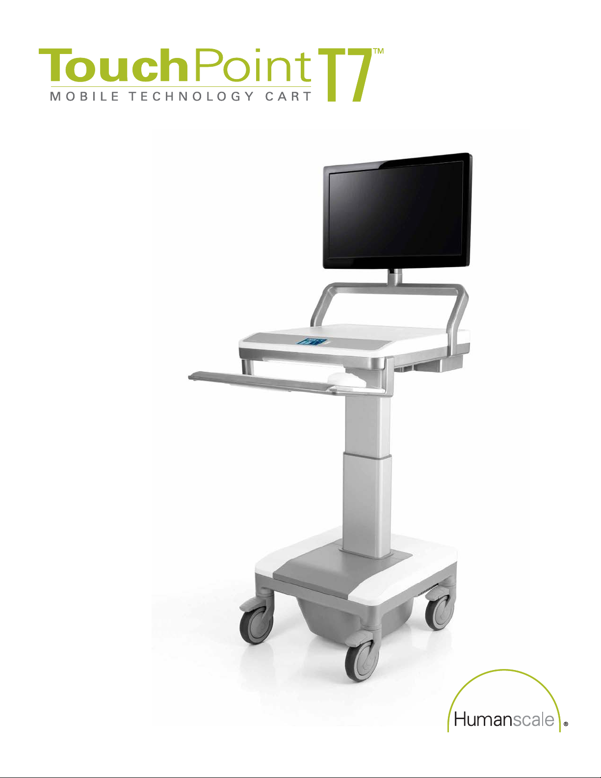
HUMANSCALE T7 POINT-OF-CARE TECHNOLOGY CART
This user manual contains information on the installation and operation
of Humanscale’s T7 Point-of-Care Technology Cart. It also contains
important maintenance information and safety requirements. Read all
instructions completely before using the T7.
TABLE OF CONTENTS
Introduction
1.0 About Humanscale Healthcare 3
1.1 Contact Information 3
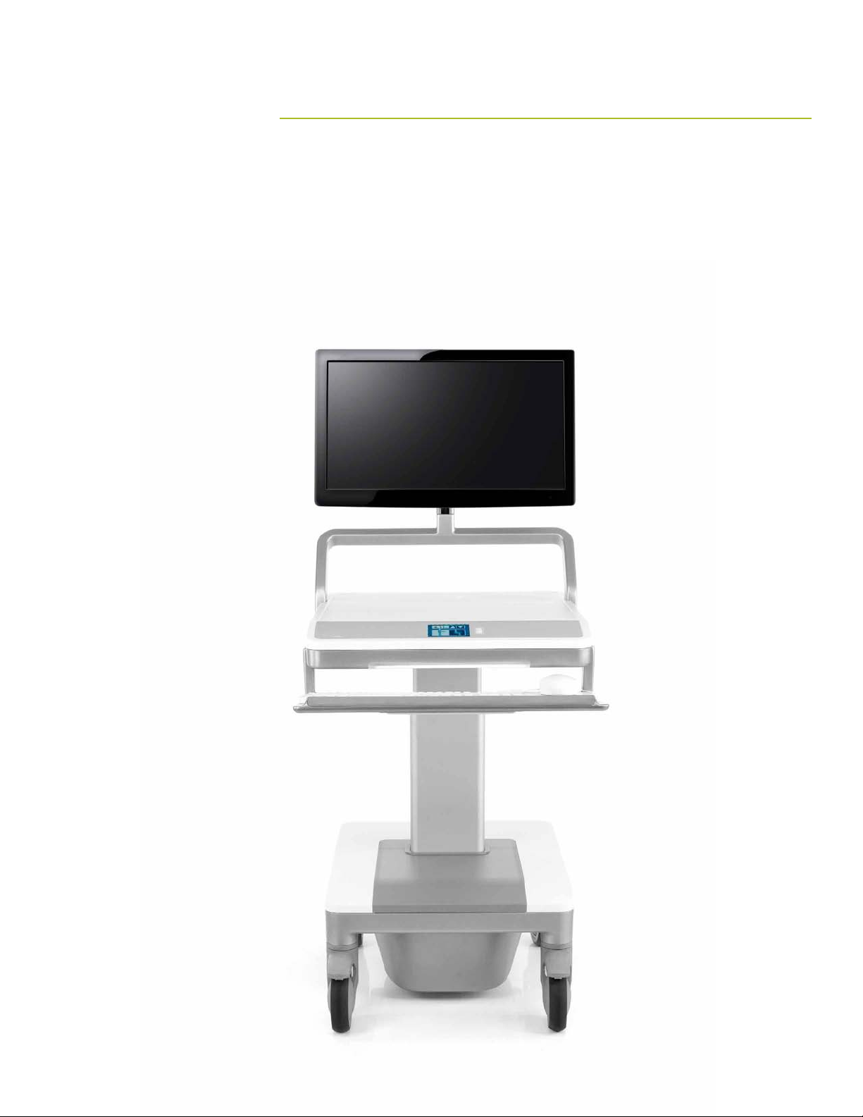
Introduction to the T7 Point-of-Care Technology Cart 4
2.0
2.1 About This Product - Frequently Used Functions 4
2.2 Cart Features 6
2.3 Technical Data 14
3.0 Using the User Interface
3.1 Interference Detection 22
Glossary of Symbols and Warnings 23
4.0
4.1 Cart Warning Review 24
15
Getting Started
5.0 Unpacking and Preassembly 27
5.1 Unpacking the T7 27
5.2 List of Par ts 28
5.3
5.4 Mounting a Monitor 31
5.5
6.0
6.1 Powered T 7 33
6.2 Power Access 33
6.3 Non-Powered T7 33
Mounting the Keyboard Tray and Gantry 29
Installing a Computer 32
T7 Configurations 33
Operation
7.0 Power System Overview 35
7.1 Initial System Startup and Shutdown 35
7. 2
7. 3
7. 4
7. 5
Proper Power System Recharging 35
Battery Level Indicator (BLI) 36
Shutdown Switch 37
Optional Remote Power Management 37
8.0 Adjusting the T7 38
8.1 Tips on Adjusting the T7 38
8.2 Ergonomic Monitor Positioning
Troubleshooting and Frequently Asked Questions 40
9.0
10.0 Accessories 40
39
Technical Information
11. 0 Maintenance and Cleaning 42
11.1
11. 2 Cart Cleaning 43
12.0 Dimensions and Range of Adjustments 44
12.1 Monitor Adjustment Range 45
13.0
13 .1 Recommended Separated Distances 46
13.2 Guidance and Manufacturer’s Declaration—
Emissions
13.3 Guidance and Manufacturer’s Declaration—
Immunity
14.0
14 .1 Shipping Environment 50
14.2 Operating Environment 50
15.0 System Messages 51
Cart Maintenance 42
Radiated Emissions 46
Shipping and Operating Environment 50
Warranty
16.0 Warranty 51
47
48
Page 3
INTRODUCTION
2
Page 4

1.0 ABOUT HUMANSCALE HEALTHCARE
Humanscale Healthcare designs and manufactures ergonomic products for easier use of today’s technology and creates a
safer and more comfortable and efficient environment for the caregiver. As part of the Humanscale Corporation, a world leader
in ergonomic design, Humanscale Healthcare brings to the healthcare market a unique understanding of the importance of
ergonomics in the workplace.
Humanscale’s products for office and healthcare environments are designed to improve the health and quality of work life,
and follow the belief that if a design solves a functional problem as simply and elegantly as possible, the resulting form will
be timeless. Humanscale Healthcare applies that same design approach to ergonomic solutions that are created to improve
the caregiving experience for caregivers and patients alike. Humanscale Healthcare’s products include the ViewPoint™ series
of technology wall stations and the TouchPoint™ line of mobile technology carts.
For more information about Humanscale Healthcare, please visit www.humanscalehealthcare.com or call 1-800- 400-0625.
1.1 CONTACT INFORMATION
Humanscale
220 Circle Drive North
Piscataway, NJ 08854
Phone:
E-mail: info
Website: www.humanscale.com
1-800-400-0625, ext. 6
@humanscale.com
3
Page 5

2.0 INTRODUCTION TO THE T7™ POINT-OF-CARE TECHNOLOGY
CART
Built with the caregiver’s work flow in mind, the T7—part of the revolutionary TouchPoint line of mobile technology carts—
addresses the challenges faced by existing medical carts by offering optimal ergonomic positioning with minimal (and often
automatic) adjustments. To reduce the risk of injuries and change the way caregivers interact with point-of-care technology,
the T7 provides simple, quick adjustments that encourage medical caregivers to work in safe postures. And its compact
footprint makes the T7 easy to maneuver and prevents parts from sticking out and breaking. Accommodating PCs, tablets
and laptops, the T7 facilitates mobile computing in healthcare environments. Humanscale, the world’s premier ergonomic
solutions manufacturer, engineered the T7 to be the new industry standard in cart technology.
2.1 A BOUT THIS PRODUCT - FREQUENTLY USED FUNCTIONS
To meet the ergonomic requirements of the vast majority of users in sitting or standing postures, the T7’s Auto Fit™
technology adjusts the unit to the caregiver’s entered height with minimal effort. By eliminating all but one adjustment step
and allowing users to enter their own specific heights, the T7 encourages users to work in an optimized ergonomic position.
Further exemplifying the T7’s sophisticated design is its Power Track™ steering, which enables caregivers to easily
maneuver in tight spaces and corridors, even with one-hand operation. And, due to its low center of gravity and centralized
mass, the T7 has excellent balance and stability for smoother, safer use. As a result, the T7 offers industry-leading
maneuverability and one of the smallest practical footprints on the market.
In addition, the digital interface, keyboard and mouse on the T7 are within the shoulder width—and therefore the ergonomic
range—of the user. The T7 includes an optional clip-on mouse platform with a cable management clip.
The T7 also offers two different tilting monitor-arm options, both of which accommodate a vast range of individuals,
including those with bifocals.
For expanded utility, the T7 offers additional storage options.
Engineered for lasting use, the T7 has a flexible power system with either an SLA or a lithium battery. In addition, the power
system and battery are readily accessible for easy maintenance by a trained Humanscale technician.
The T7 has a completely encased wire management system, which mitigates both clutter and infection-control concerns. In
any setting, the T7’s streamlined design makes cleaning easy and promotes a healing environment. The construction of the
T7 consists primarily of durable aluminum, with steel and plastic components.
4
Page 6
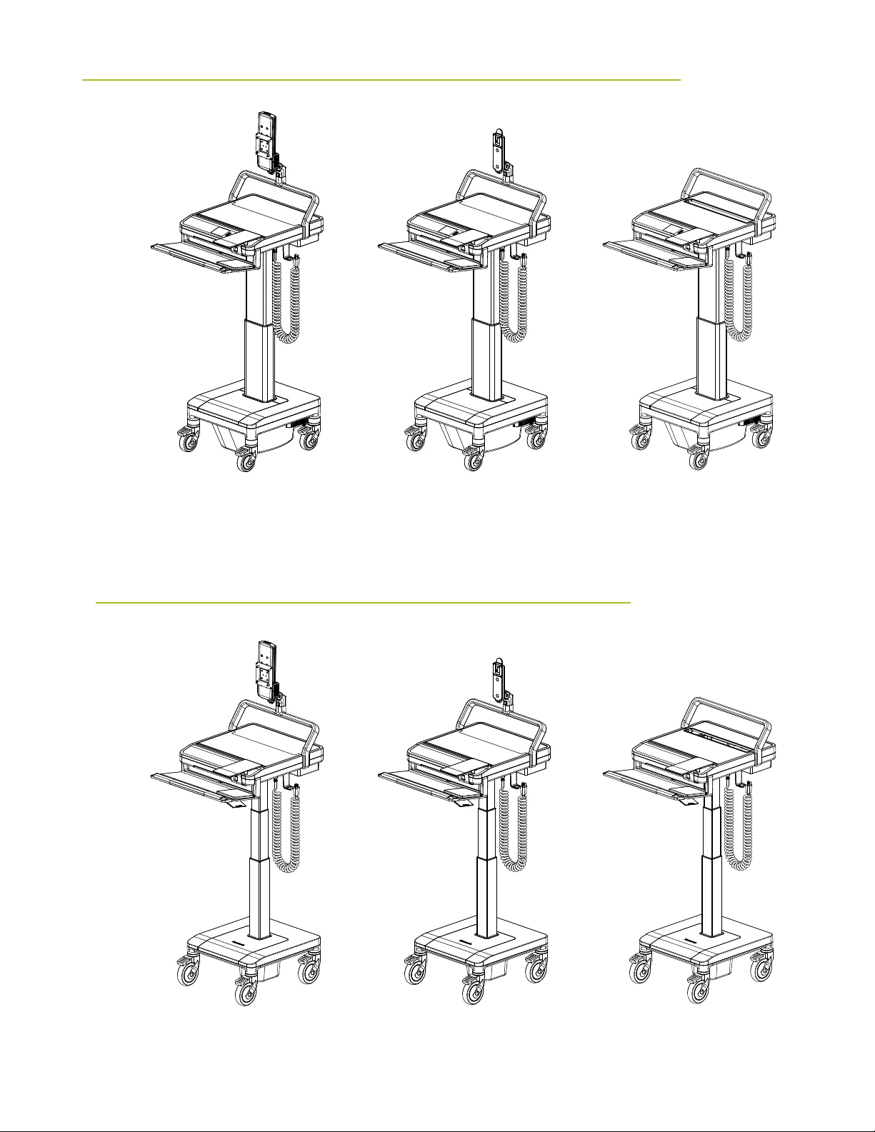
T7 POWERED
T7 Powered
Adjustable Monitor
T7 Powered
Fixed Monitor
T7 Powered
Laptop
T7 NON-POWERED
T7 Non-Powered
Adjustable Monitor
T7 Non-Powered
Fixed Monitor
T7 Non-Powered
Laptop
5
Page 7

2.2 CART FEATURES
Humanscale’s T7 point-of-care mobile technology cart offers unprecedented
ease of adjustment for each user in a shared work environment, providing
one, simple, combined adjustment for the work surface, keyboard support
and display. The T7’s 20” (50.8 cm) height range ensures comfortable
ergonomic accommodation for seated and standing workers. (See Section
8.0 Adjusting the T7, page 37)
Features:
1. Auto Fit Technology (height adjustment): The T7 features Auto Fit technology accessible via a digital dashboard interface.
Anthropometric data determines the eye levels and elbow heights associated with certain overall heights of users. As such,
the T7’s monitor and work surface/keyboard are designed to adjust to the ergonomically optimal eye and elbow level for
each user according to the overall height each user enters in the digital dashboard interface.
2. Keyboard Support: The keyboard support is fixed at a negative title angle so that the user’s wrist is kept in a straight line
to the elbow when the work surface has been ergonomically adjusted for the user’s height, and, as such, encourages
ergonomically safe positions that help prevent such musculoskeletal disorders as carpal tunnel syndrome.
3. Handle/ Palm Rest: Acting as a palm rest for the keyboard, the handle also features the Power Track steering button on its
underside.
4. Mouse Position: Two options for fixed mouse platform are available, both of which keep the mouse within the footprint of
the cart and maximize ergonomic positioning.
5. Gantry: Serving as a back handle for the cart and as cable management, the gantry raises the monitor support above the
work surface, providing more work surface while guiding the cart.
6. Large, Clean Work Surface: Ample work surface space allows for greater utility.
7. Stride and Toe Clearance: Positioning of the keyboard platform allows the handle to be far enough from the base of the cart
to leave room for full strides and toe clearance when walking.
8. Power Track Steering: Increasing control, the Power Track Steering directs the weight of the cart and aids the user in
moving it in the intended direction. To engage the system, users must simply press the button on the underside of the
palm rest.
9. PC and Laptop Accommodation: The T7 can support all-in-ones, laptops, thin clients and small form factor PCs, based on
various mounting options available.
10. Screen Moving with Work Surface to Correct Position: Since the monitor is constrained to the work surface, it moves up
and down as the work surface is raised and lowered.
11. Screen Can Be Moved by User to Desired Position: The monitor on select models can also be raised and lowered
independent of the work surface, to account for people with varying torso lengths. The user can adjust the height of the
monitor as desired.
12. Moving Screen for Bifocal Use: All models include the possibility for the user to tilt the monitor to help accommodate the
use of bifocals.
13. Monitor Arm: Provides 15 degrees of tilt and rotates 90 degrees for viewing access and sharing content with patients.
6
Page 8
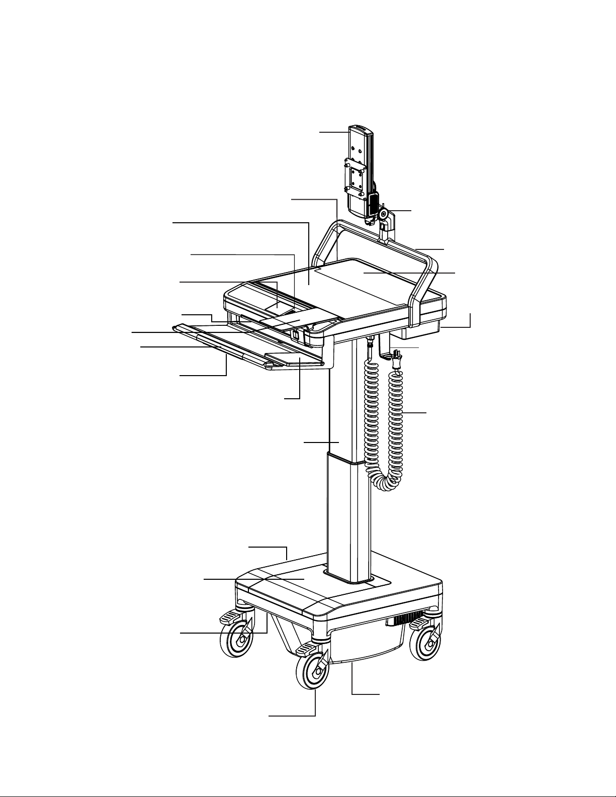
T7 Powered Adjustable Monitor
Adjustable-Height Monitor Mount w/
Standard VESA FDMI MIS-D; 100/75, C
Monitor Interface
Front of Work Surface with
Enclosed CPU Storage Option
Battery Level Indicator on the Dashboard
Touch Screen Interface for AutoFit
Height Adjustment
Automatic LED Lighted Keyboard Area
Optional Mouse Platform
Silicone Palm Rest
Power Track Steering Actuator Button
(underneath handle)
(underneath work surface)
Power Button
Standard Mouse Platform
Quiet, Automated Lifting Mechanism
20” Height Adjustment
Rotating and Tilting Monitor Arm
Rear Handle and Cable Management
Back Panel of the Work Surface
PC Power Supply Storage and
Internal Cable Management
Power Cable Hook
Coiled AC Power Cable
(underneath base)
Rechargeable SLA or LiON Battery Option
Toe Clearance
Heavy-duty 4” Casters w/ Front
Circuit Breaker
Power Track Steering Option
Locking Mechanism
7
Page 9
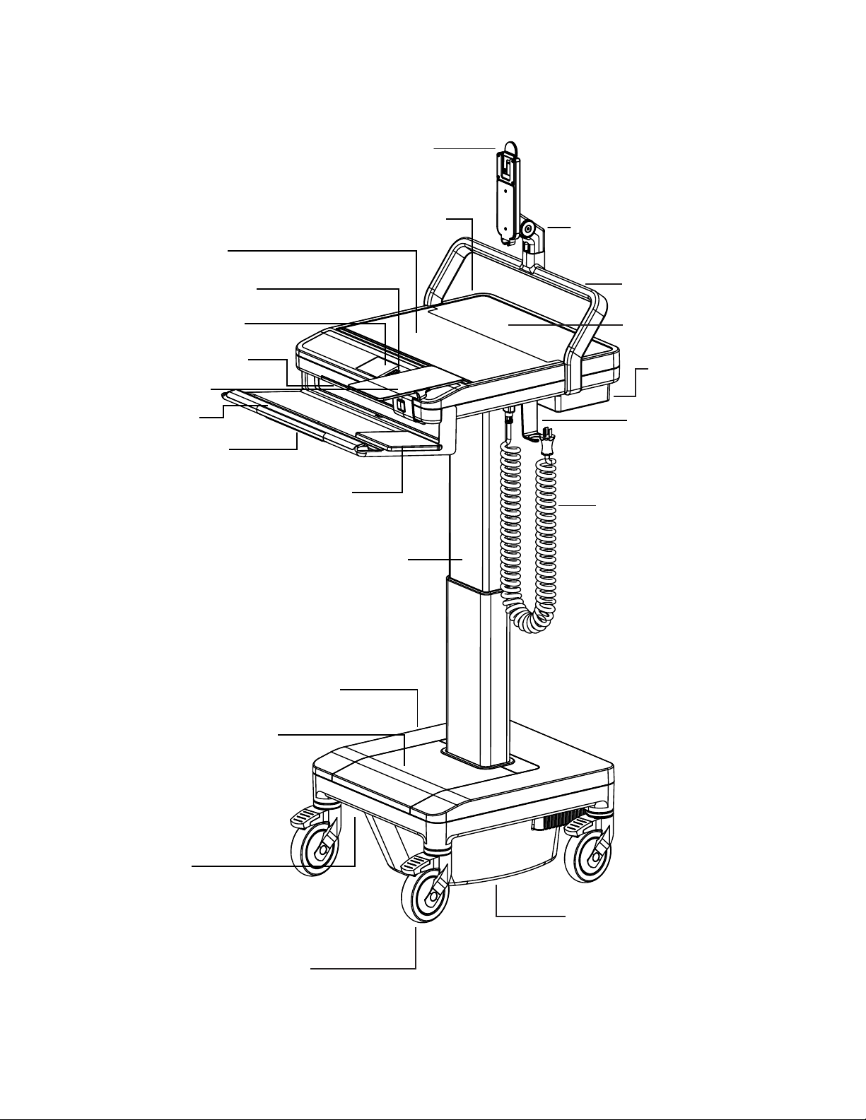
T7 Powered Fixed Monitor
Fixed Height Monitor Mount
Front of Work Surface with
Enclosed CPU Storage Option
Battery Level Indicator on the Dashboard
Touch Screen Interface for AutoFit
Height Adjustment
Automatic LED Lighted Keyboard Area
Optional Mouse Platform
Silicone Palm Rest
Power Track Steering actuator
(underneath handle)
Standard Mouse Platform
Quiet, Automated Lifting Mechanism
(underneath work surface)
Power Button
20” Height Adjustment
Rotating and Tilting Monitor Arm
Rear Handle and Cable Management
Back Panel of the Work Surface
PC Power Supply Storage and
Internal Cable Management
Power Cable Hook
Coiled AC Power Cable
Rechargeable SLA or LiON Battery Option
Toe Clearance
Heavy-duty 4” Casters w/ Front
Locking Mechanism
8
Circuit Breaker
(underneath base)
Power Track Steering Option
Page 10
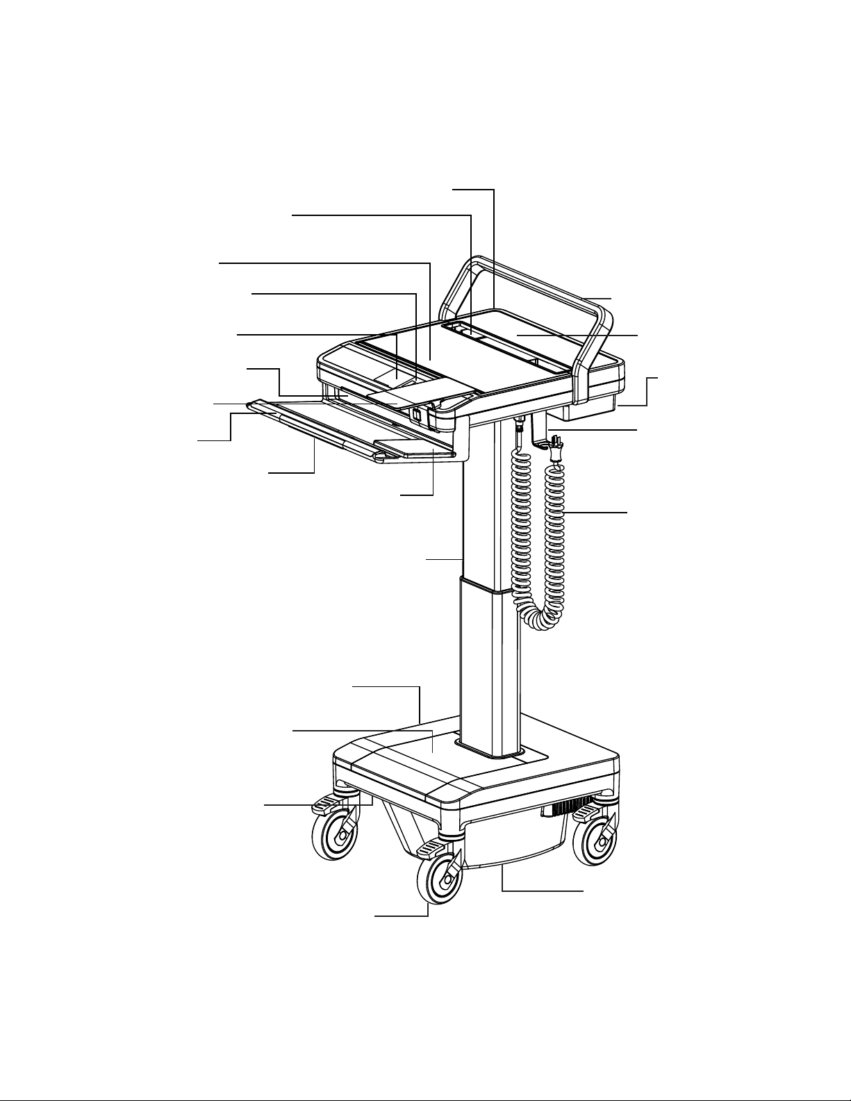
T7 Powered Laptop
Laptop Screen Opening
Front of Work Surface with
Enclosed Laptop Storage Option
Battery Level Indicator on the Dashboard
Touch Screen Interface for AutoFit
Height Adjustment
Automatic LED Lighted Keyboard Area
Optional Mouse Platform
Silicone Palm Rest
Power Track Steering Actuator
(underneath handle)
(underneath work surface)
Power Button
Rear Handle and Cable Management
Back Panel of the Work Surface
PC Power Supply Storage and
Internal Cable Management
Power Cable Hook
Standard Mouse Platform
Coiled AC Power Cable
Quiet, Automated Lifting Mechanism
20” Height Adjustment
(underneath base)
Rechargeable SLA or LiON Battery Option
Toe Clearance
Heavy-duty 4” Casters w/ Front
Circuit Breaker
Power Track Steering Option
Locking Mechanism
9
Page 11
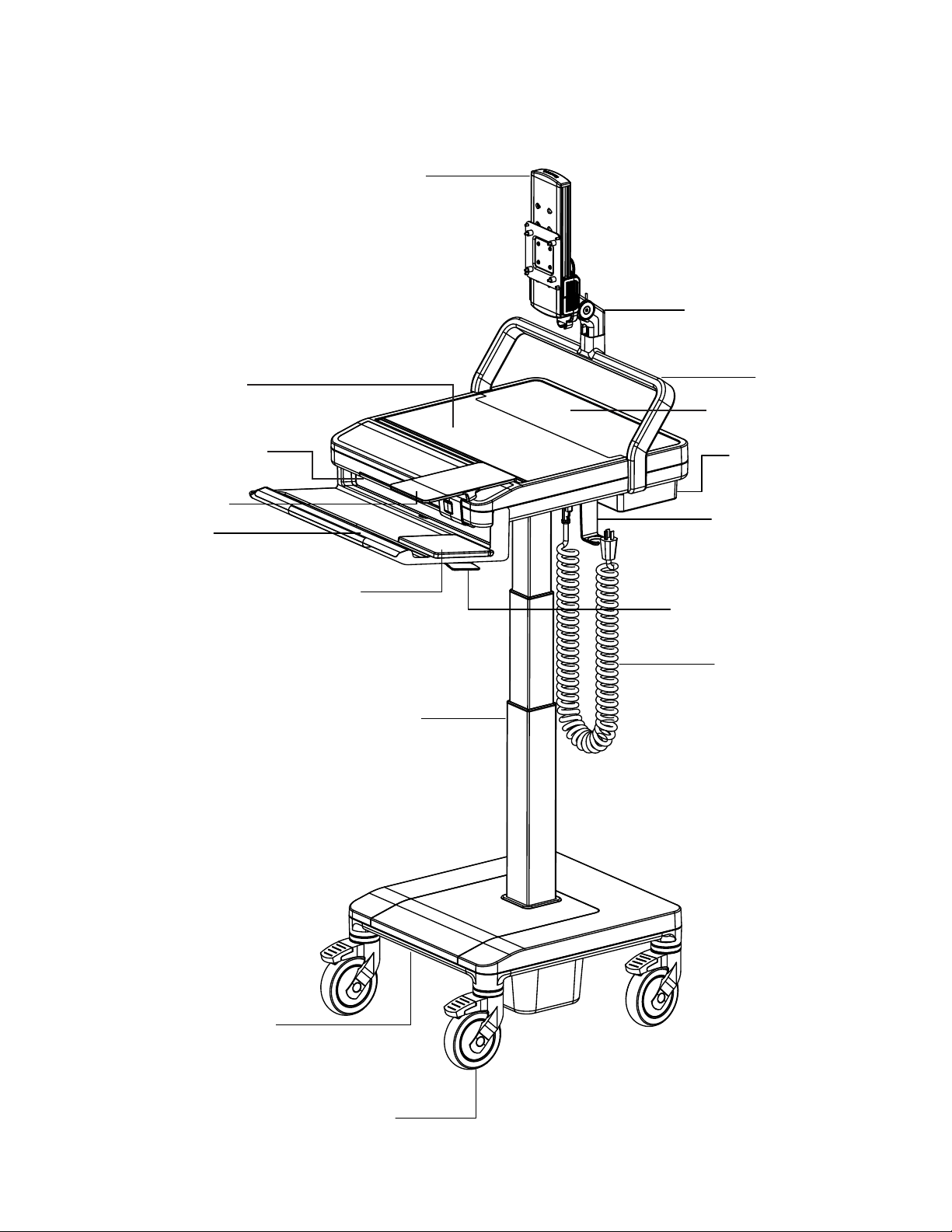
T7 Non-Powered Adjustable Monitor
Adjustable-Height Monitor Mount w/
Standard VESA FDMI MIS-D; 100/75, C
Monitor Interface
Rotating and Tilting Monitor Arm
Front of Work Surface with
Enclosed Laptop Storage Option
Automatic LED Lighted Keyboard Area
Optional Mouse Platform
Silicone Palm Rest
Standard Mouse Platform
Rear Handle
Back Panel of the Work Surface
PC Power Supply Storage and
Internal Cable Management
Power Cable Hook
Height Adjustment Actuator Handle
Coiled AC Power Cable
Lifting Mechanism
20” Height Adjustment
10
Toe Clearance
Heavy-duty 5” Casters w/ Front
Locking Mechanism
Page 12
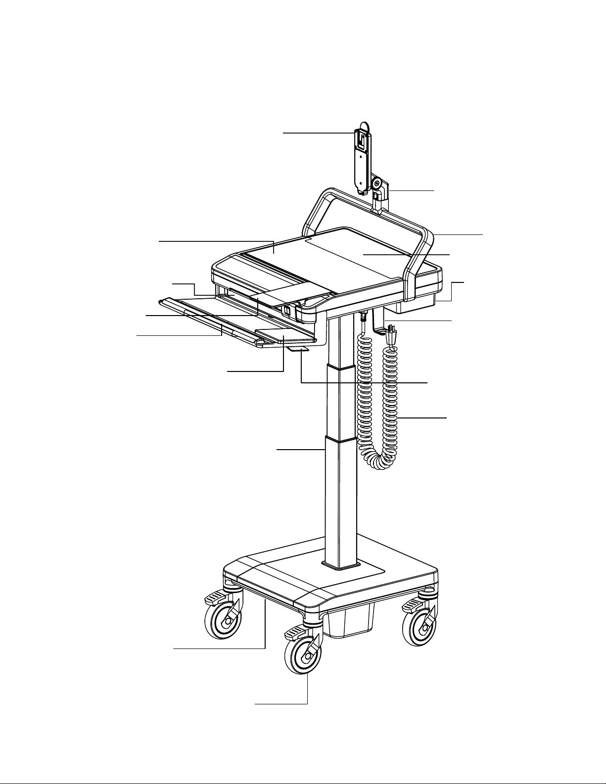
T7 Non-Powered Fixed Monitor
Fixed-Height Monitor Mount
Rotating and Tilting Monitor Arm
Front of Work Surface with
Enclosed Laptop Storage Option
Automatic LED Lighted Keyboard Area
Optional Mouse Platform
Silicone Palm Rest
Standard Mouse Platform
Rear Handle
Back Panel of the Work Surface
PC Power Supply Storage and
Internal Cable Management
Power Cable Hook
Height Adjustment Actuator Handle
Coiled AC Power Cable
Lifting Mechanism
20” Height Adjustment
Toe Clearance
Heavy-duty 5” Casters w/ Front
Locking Mechanism
11
Page 13

T7 Non-Powered Laptop
Laptop Screen Opening
Front of Work Surface with
Enclosed Laptop Storage Option
Automatic LED Lighted Keyboard Area
Optional Mouse Platform
Silicone Palm Rest
Standard Mouse Platform
Rear Handle
Back Panel of the Work Surface
PC Power Supply Storage and
Internal Cable Management
Power Cable Hook
Height Adjustment Actuator Handle
Coiled AC Power Cable
Lifting Mechanism
20” Height Adjustment
12
Toe Clearance
Heavy-duty 5” Casters w/ Front
Locking Mechanism
Page 14
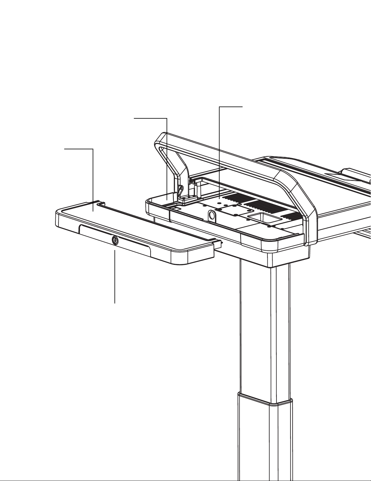
T7 Rear Locking Panel (all models)
Interior Space with Available AC Power
Removable Panel
Inside Shelf for Laptop
Lock
13
Page 15
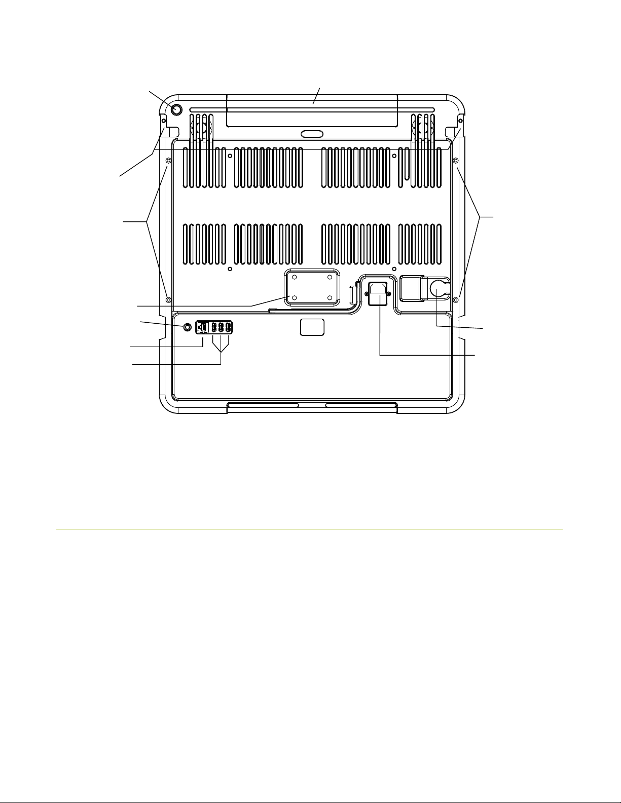
Work Surface Bottom
PC Reset Button
Keyboard Frame
Mounting Holes
Work Surface Cover
Mounting Holes
Lifter Mount
Main Power Button
RJ45 Jack
USB Ports
Keyboard Surface Light
Work Surface Cover
Mounting Holes
AC Cord Hanger
AC Input
USB/ RJ45 Ports are specifically for the connection and use of the following components:
• Barcode Scanner
• External PC
• Mouse
• Printer
• Document Scanner
• USB Hub
• Blood Pressure Monitors
• Humanscale Branded Accessories
2.3 TECHNICAL DATA
AC Power System
• 120 VAC, 60 Hz, input
• 120 VAC pure sine wave, 60 Hz, 150 W output
• 150 VA, peak power up to 250 VA
Battery
• Sealed Lead Acid (SLA)
- 480 W (35 Amp Hour), 12 V output
• Lithium Iron Phosphate
- 45 amp hour
- 12.8 V output
- 2,000 cycles at 80% depth of discharge (DOD)
- 2½ hours recharge time
- Limited 5year warranty
Battery Level Indicator (BLI)
• Indicates charging status
• Battery level
Flat-Panel Display Dimensions
• The T7 accommodates most flat-panel
displays weighing up to 12.5 lbs.
Computer Dimensions
• The T7 work surface can accommodate a
computer up to 17.35” L by 12.3” W by 2.25”
H and has a 16.8”-wide opening for a laptop
screen.
14
Page 16
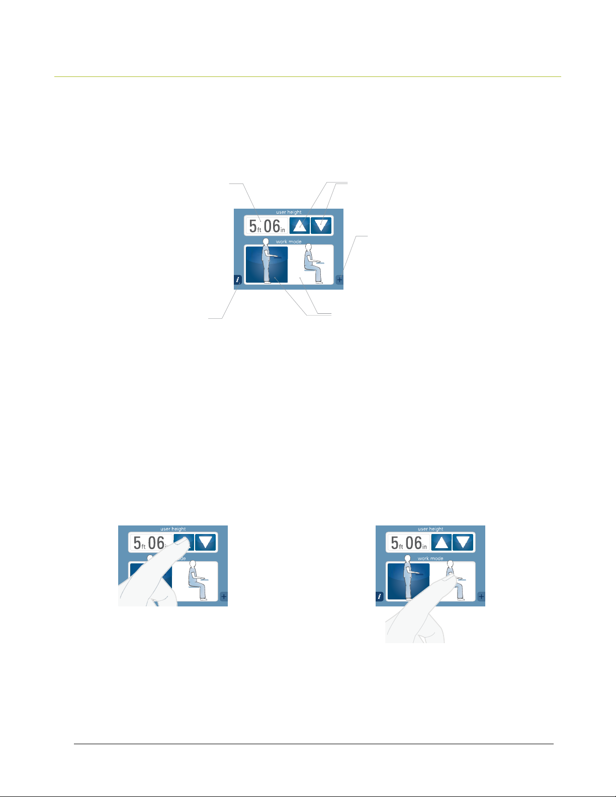
3.0 USING THE USER INTERFACE
We should have a note here
saying the height range:
4’ 11” - 6’ 3”
Adjusting Height (4’ 11” – 6’ 3”)
Manual height adjustment screen
Selected height indicator
Info
Manual height input
The following steps can be executed in any order:
Height adjustment
Change to preset height mode
Sit/ stand mode
1
Field- installed power systems must be installed by an authorized, trained technician
User enters his/her heightcart adjusts accordingly.
CART WILL
MOVE A
SMALL AMOUNT
User selects sit/stand modecart adjusts accordingly.
CART WILL
MOVE
SIGNIFICANTLY
15
Page 17
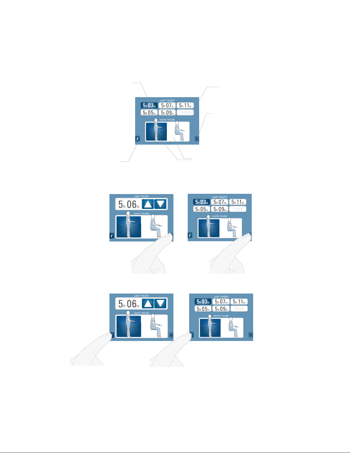
Adjusting Height
Preset height adjustment screen
Preset Buttons
Info
Changing from manual
mode to preset mode.
New preset available
Change to manual mode
Sit/stand mode
Changing from preset
mode to manual mode.
16
Info screen for manual mode. Info screen for preset mode.
Page 18
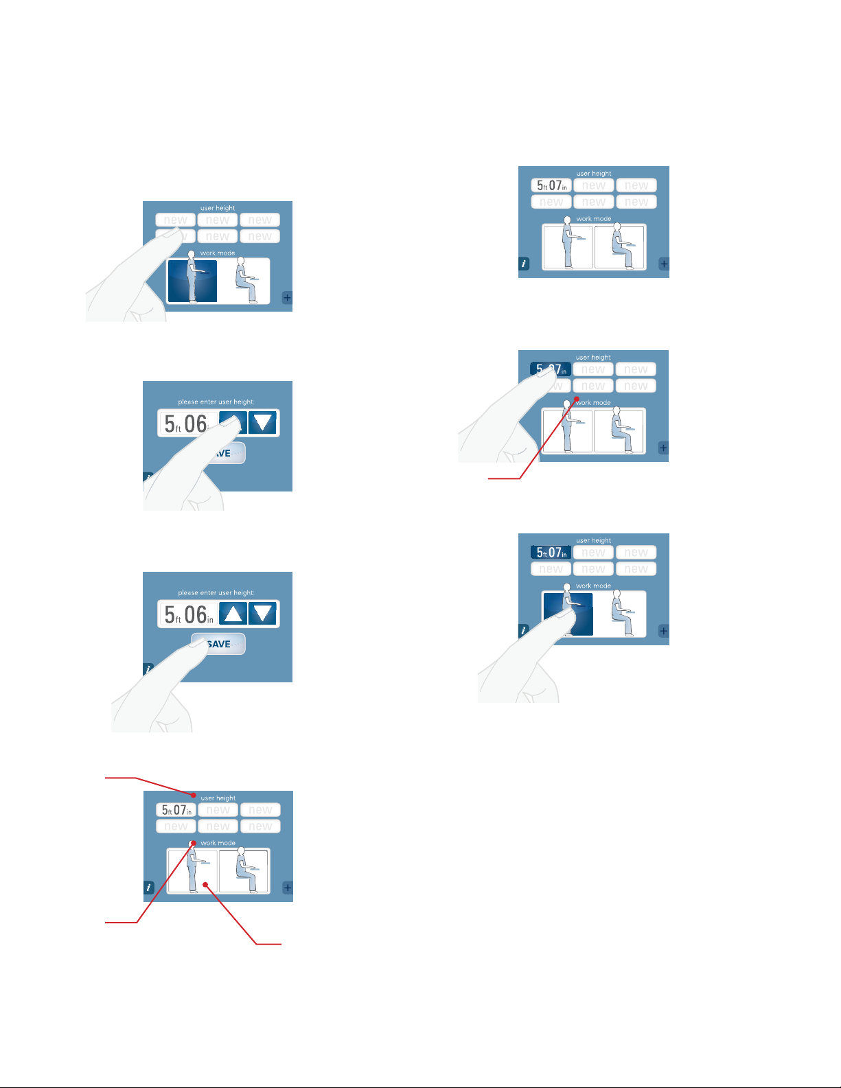
Adjusting Height
Adjusting Height
Preset mode-new height input
For the first height entered,
hold any of the “new” buttons
down for 4 seconds.
CART DOESN’T
MOVE
Select your height.
CART DOESN’T
MOVE
Blinking“work
mode” text
indicates
that action is
required
Using the preset height screen
for the first time
Preset height will appear on screen
CART DOESN’T
MOVE
Select your preset height
CART DOESN’T
MOVE
Select sit or stand work mode–cart will
adjust to the selected height that is set
Blinking “user
height” text
indicates
that action is
required
Blinking“work
mode” text
indicates
that action is
required
Save your height as preset.
Preset height will appear on
the preset screen.
“Work mode” section is
all white because there
is no selection made yet
CART DOESN’T
MOVE
CART DOESN’T
MOVE
CART MOVES TO
THE SELECTED
HEIGHT POSITION
17
Page 19
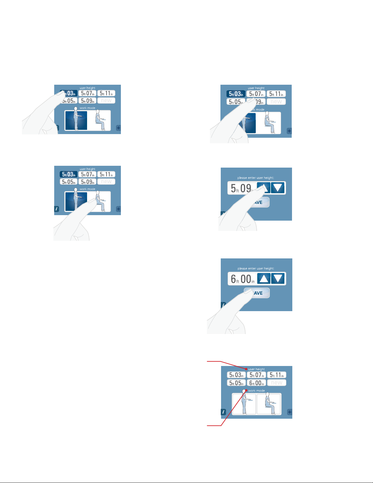
Adjusting Height
Adjusting Height
Using the preset height screen
Select your preset height.
Select sit or stand work mode–cart
will adjust to the selected height.
CART MOVES TO
THE SELECTED
HEIGHT POSITION
Modifying presets
To modify an entry, hold any of the
buttons down for 4 seconds.
CART DOESN’T
MOVE
Adjust your height using the arrows.
CART DOESN’T
MOVE
Blinking “user
height” text
indicates
that action is
required
Blinking“work
mode” text
indicates
that action is
required
Save your new preset height.
CART DOESN’T
MOVE
The modified preset height will
appear on the preset screen
CART DOESN’T
MOVE
18
Page 20
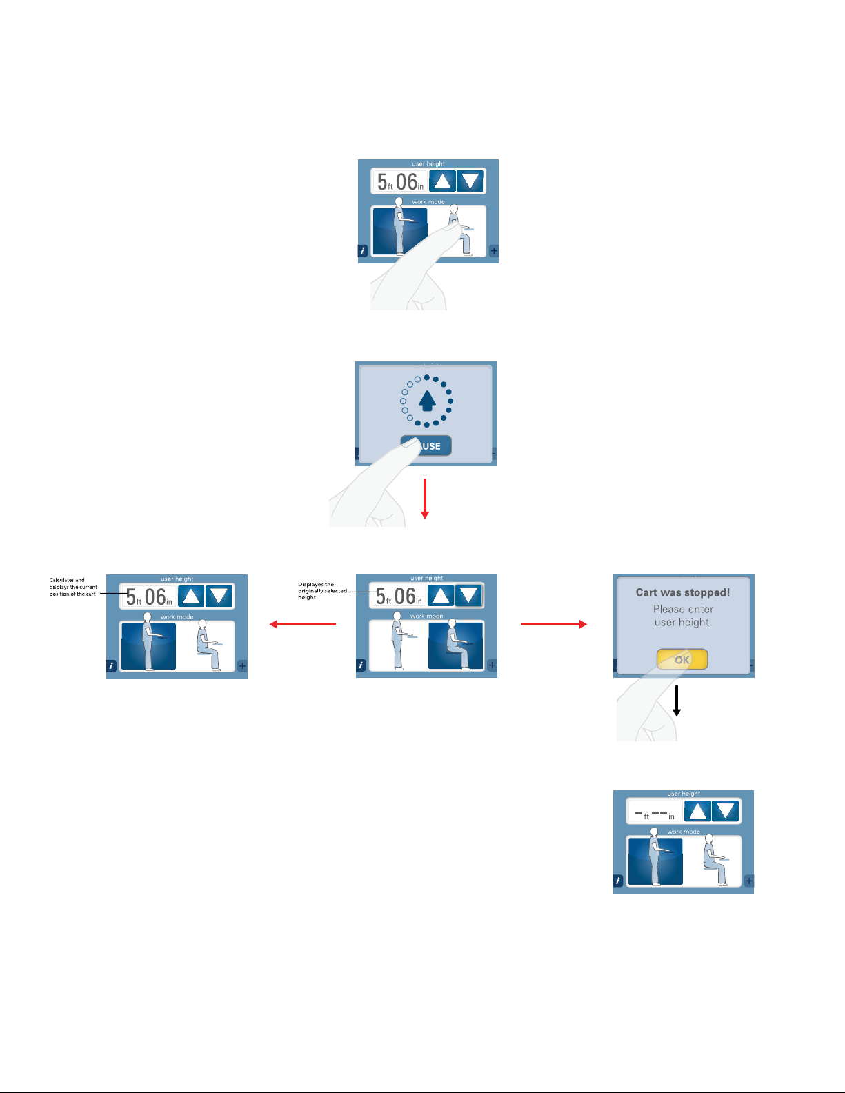
Stopping the Cart’s Movement
Stopping the adjustment in manual mode
If you need to stop the adjustment, you
will see the below screen. Press pause.
Screen returns to user input mode. Screen returns to user input mode.
If you don’t input
a new height or
select sit /stand,
the cart will, in
some instances,
calculate the
current height of
the cart.
This screen may
pop up if the cart is
unable to calculate
height. Select OK
and enter proper
height. All error
messages have
the same light blue
background and
yellow button.
Screen returns to a blank user
input mode. Enter user’s height.
19
Page 21
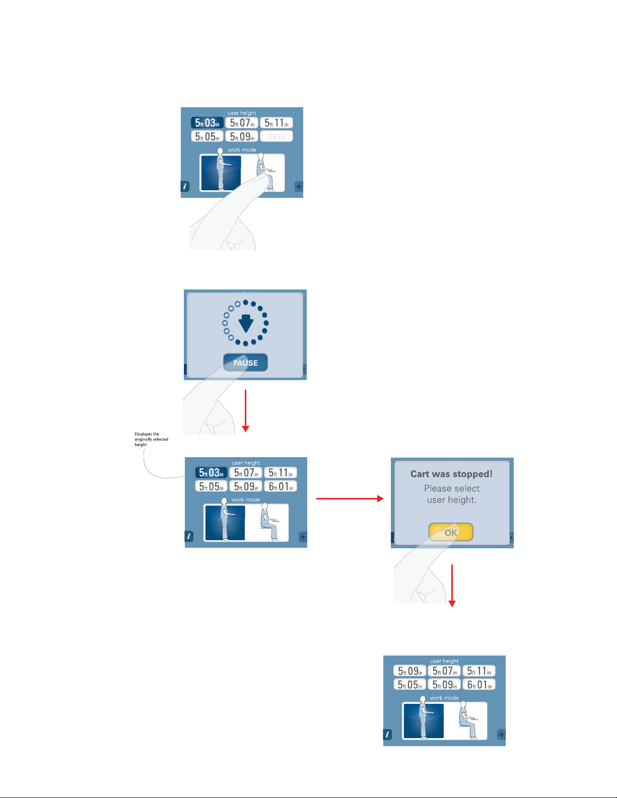
Stopping the Cart’s Movement
Stopping the adjustment - preset mode
If you need to stop the adjustment, you
will see the below screen. Press pause.
If cart is unable
to calculate
entered height,
click OK.
Screen returns to the input mode
screen where no height is selected.
Select preset height.
20
Page 22
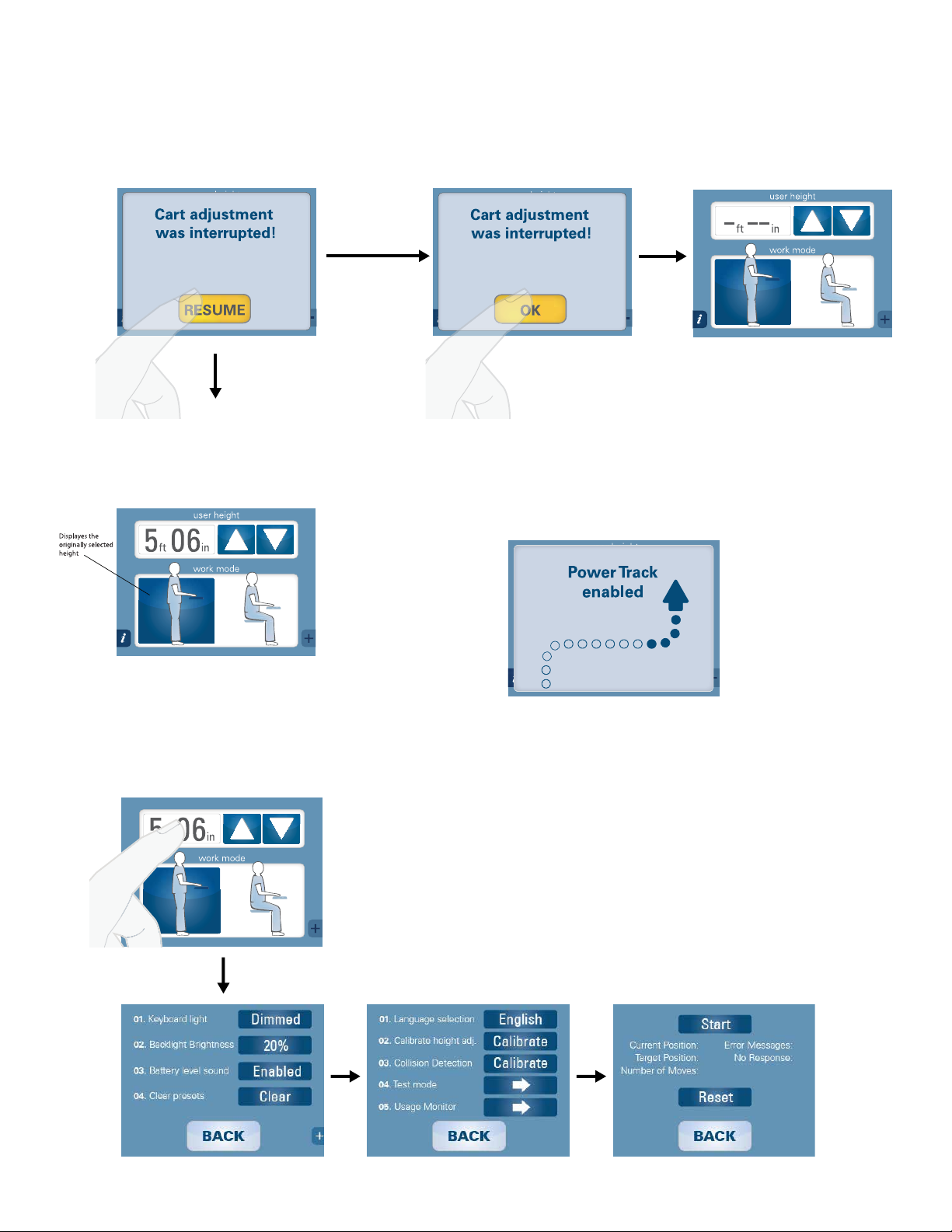
Collision Messages
Clear perimeter
and continue.
Clear perimeter and
enter user's height.
In the event that the cart’s vertical movement could cause a collision, the following error messages
(light blue boxes with yellow buttons) may appear.
In some
instances,
the cart will
not move.
Screen returns to blank
user input mode
Clear the perimeter of the cart and press
resume. The cart will move after you hit
resume. Enter the correct height.
Access IT Menu
Press the height display for 5 seconds
Power Track Screen
The following screen appears and remains
until the Power Track feature is disengaged.
21
Page 23

3.1 I NTERFERENCE DETECTION
From the LINAK User Manual:
Anti-collision
The anti-collision function is a new option for the standard CBD4/ CBD5 advanced/control box software version 1.66 and later.
A system with anti-collision can limit material damages on a desk if a collision with a solid object should occur.
Situations in which the anti-collision function does not work
There are situations in which the anti-collision function will not be activated.
These situations are:
• If the collision happens during the initialization phase
• If the collision happens within the first 1,000 msec or after the control button has been released
• If the collision happens between the floor and the table and the load on the desk plus the weight of the legs is lower
than 40 kg
• If the collision happens over too long a time, e.g., if the collision is with a soft object.
22
Page 24
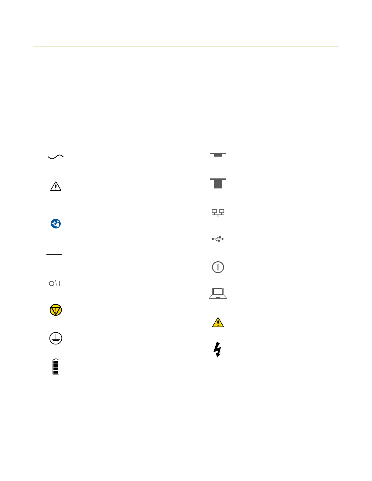
4.0 GLOSSARY OF SYMBOLS AND WARNINGS
These symbols provide alerts to safety conditions demanding attention. It
is important to recognize and understand the significance of the following
safety hazards when encountered on the T7 Point-of-Care Technology Cart
or within the manual.
Alternating Current
IEC 60601-1, 2nd ed. Mandatory to
Consult Accompanying Documents
IEC 60601-1, 3rd ed. Mandatory to
Consult Accompanying Documents
Direct Current
ON/OFF Power Switch
Emergency stop
Circuit Breaker Engaged (up)
Circuit breaker disengaged (down)
RJ 45 Connection
USB 2.0 Connection
Push-button on/off switch
PC/ CPU reset
General Warning Sign
Protective Earth (ground)
Battery Level Indicator
Dangerous Voltage
23
Page 25
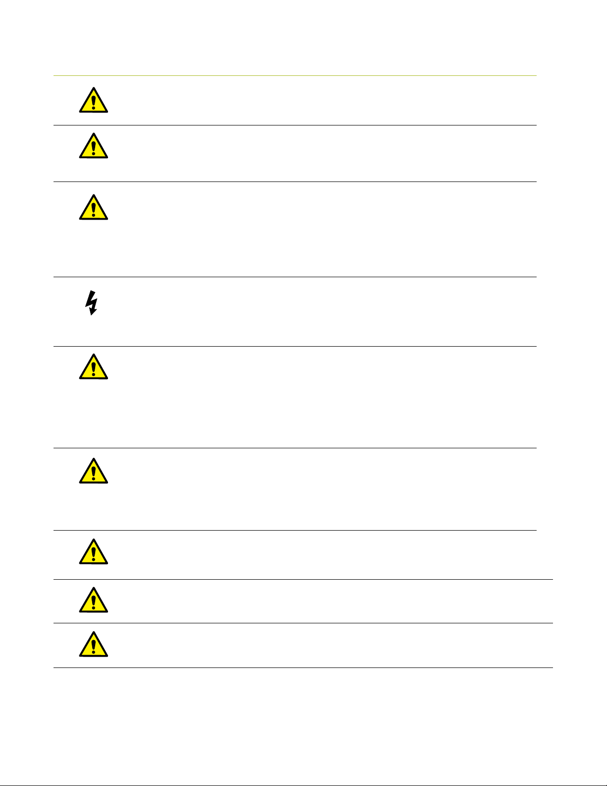
4.1 C ART WARNING REVIEW
BATTERY REPLACEMENT
To maintain certification, replace the T7’s battery with a Humanscale replacement battery only.
SERVICE AND REPLACEMENT
Maximum Weights
Monitor
Laptop tray
GROUNDING
Connect the T7 to an equivalent receptacle marked “Hospital Only” or “Hospital Grade” to ensure
a protective earth ground.
Do not attempt to service the system while the power is on. Do not attempt to service or replace
any part of the T7 unless directed to do so through Humanscale-approved documentation (i.e., this
User Manual or other instructions). Only Humanscale or a Humanscale-certified entity may service or
replace the cart components. If any component on the cart is missing or damaged, the cart must not
be used. Contact Humanscale Customer Service immediately to request service.
DANGEROUS VOLTAGE
Do not remove the base cover—there may be electrical energized components, even when the T7 is
in standby mode. Opening of the base by unauthorized personnel may cause injury and/or death.
If the unit is not working properly, please contact Humanscale at 1-800-400- 0625.
DANGEROUS VOLTAGE
Safe working loads must be abided by for all parts of the T7.
15 lbs. Keyboard Tray 5 lbs.
15 lbs.
holding the power button under the back right corner of the work surface (if standing in front
of the cart), and pulling the circuit breaker switch under the left side of the base. W ipe away
any excess liquid and allow it to dry before use.
DO NOT USE THE UNIT IN OR NEAR WATER OR OTHER LIQUIDS.
If the unit becomes wet, power it off immediately by unplugging the AC power cord from the wall,
DO NOT IMMERSE THE POWER SYSTEM IN WATER.
This is an electrical hazard and can cause damage to the unit, as well as injury to the user.
USE A NONFLAMMABLE CLEANER WHEN CLEANING THE UNIT.
Failure to do so can result in death, explosion and/or fire. Always unplug the unit before cleaning.
DO NOT LEAVE THE UNIT UNATTENDED AROUND CHILDREN.
Failure to do so can result in injury and/or death.
24
Page 26
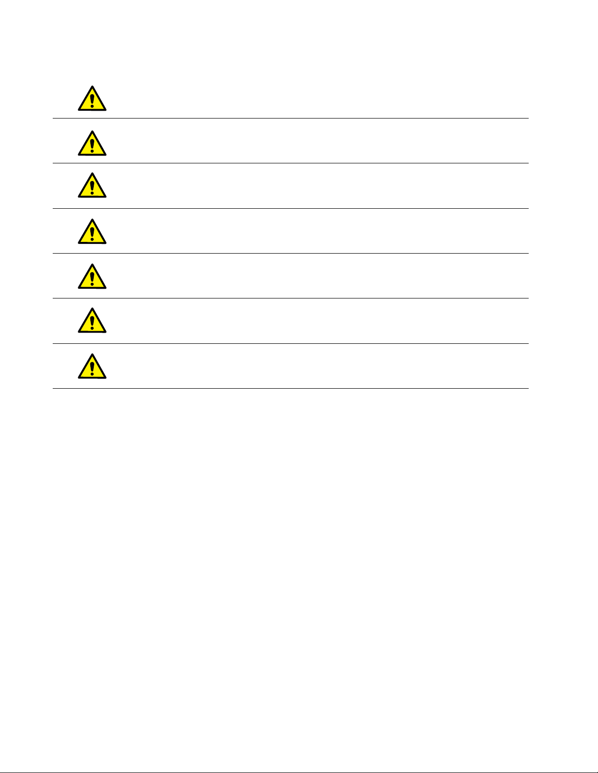
Connecting electrical equipment to the Multi-Socket Outlet effectively leads to creating a Medical
Electrical system and can result in a reduced level of safety
An extension cord or additional Multi-Socket Outlet may not be connected to the T 7’s integrated
Multi-Socket Outlet
Only equipment to be used as part of the T7 system or compatible with power requirements may
be connected to the Multi-Socket Outlet for power
Potential loss of data if battery runs out of power. Plug in AC cable to charge battery if the low-battery
alarm sounds
The Non-powered T7 cart may have greater risk of leakage current with user-installed technology
on-board
Installing technology in the Non-Powered T7 will pose a greater risk of hazard due to liquid spills.
Extra precaution should be taken.
A hazardous risk of tipping exists when the T7 encounters a step up or down of 40mm (1.5”) or greater,
proceed with caution or find assistance in moving the cart over a change of height of this magnitude.
25
Page 27
GETTING STARTED
26
Page 28
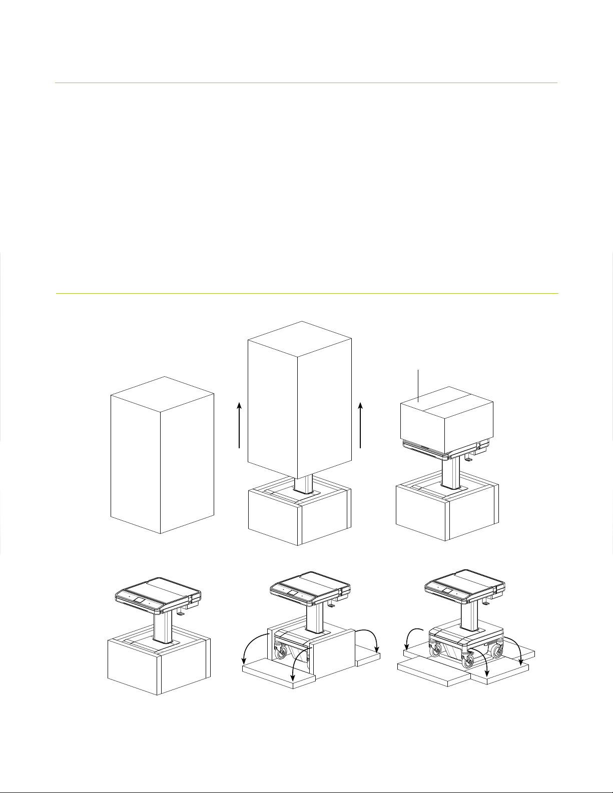
5.0 UNPACKING AND PR EA SSEM BLY
The T7 Point-of-Care Technology Cart should arrive upright inside a
cardboard carton strapped with two plastic straps. Inside the main carton
is a smaller cardboard container storing all standard and optional hardware.
The entire outer packaging should be plastic shrink-wrapped. Removal of the
T7 from the packaging must proceed as follows to avoid damage and the
possibility of lost parts.
5.1 UNPACKING THE T7
Remove hardware box and set asi de
*For safet y reasons, two people
are require d to remove the T7
from the pallet
27
Page 29
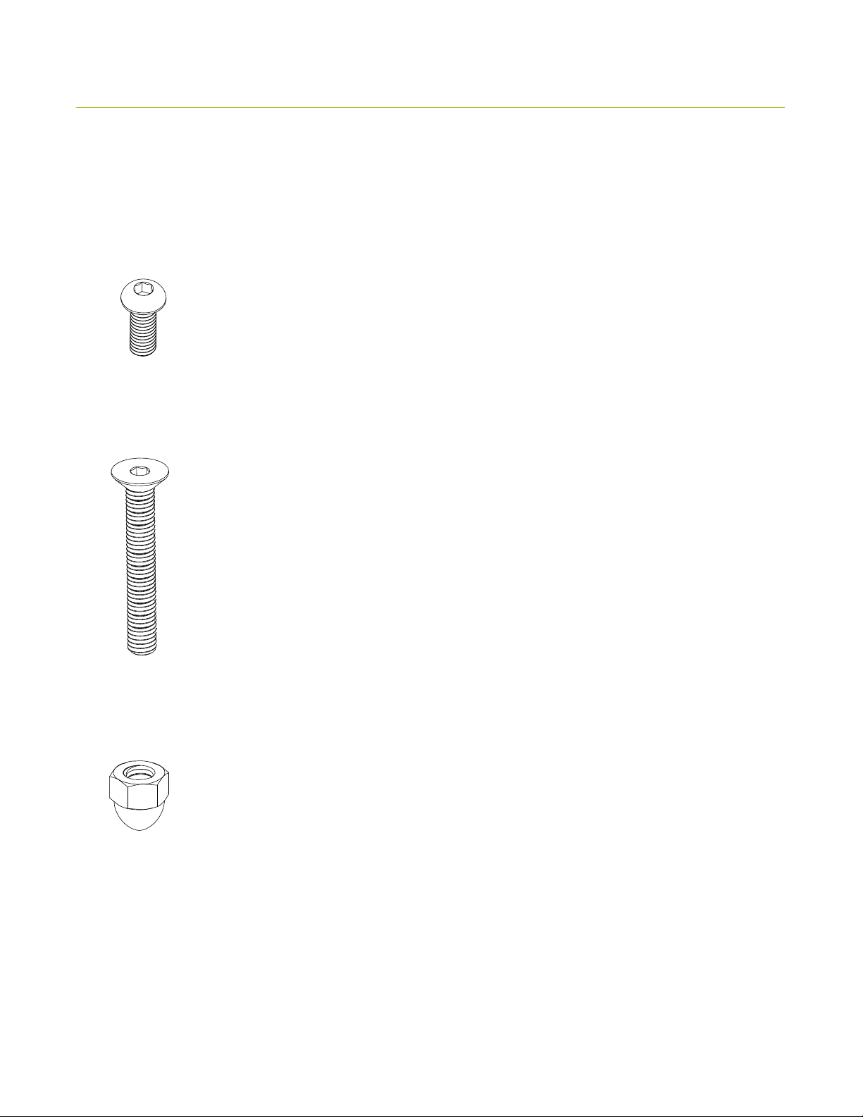
5.2 LIST OF PARTS
Some standard and optional accessories will ship disassembled from the T7. These items will be packaged separately and
will need to be installed by following the instructions in this manual. Refer to the following List of Parts for help identifying
the proper hardware to be used when installing these accessories.
M6 x 16 mm Button Head Cap Screw
Quantity 6—Gantry and Keyboard Frame Mounting
M5 x 35 mm Flat Head Screws
Quantity 4— Height Adjustable Release
Paddle Mounting
M5 Acorn Nuts
Quantity 4—Height Adjustable
Release Paddle Mounting
28
Page 30
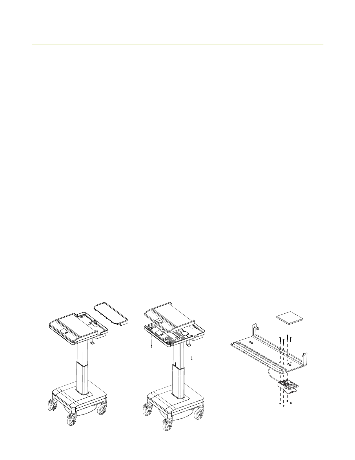
5.3 MOUNTING THE KEYBOARD TR AY AND GANTRY
The T7 comes equipped with an external, ergonomic keyboard frame and rear gantry handle. These are packaged in the
accessories box that comes in the T7 crate. Before the T7 is ready for use, you or a service technician must install the
keyboard frame and gantry.
Mounting the Keyboard Frame
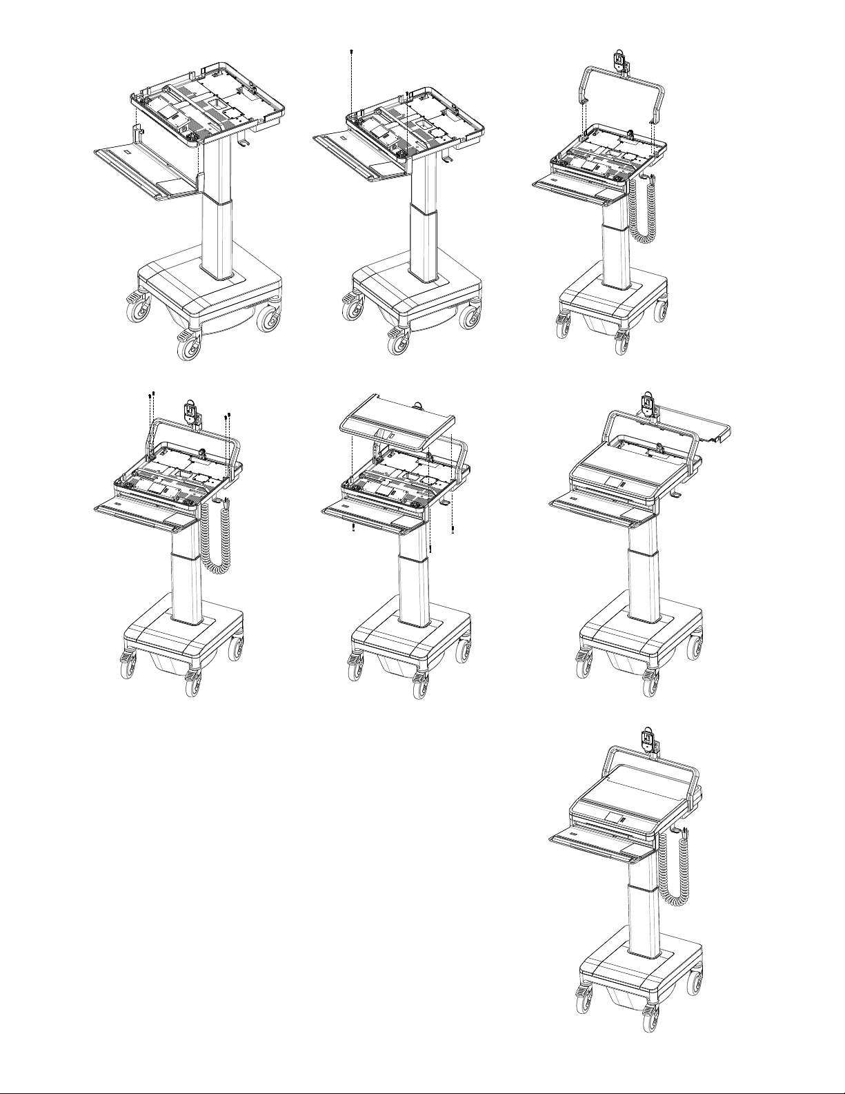
1. Remove the rear work surface cover from the T7 and set it aside. (fig. 1)
2. Unscrew the four screws holding the front work surface cover to the frame and lift it off. Set the cover aside where it will
not be damaged. ( fig. 2)
3. Unpack the keyboard frame and using 4 long screws and 4 nuts attach the height adjustable release paddle to underside of
tray. (fig. 3) - *NOTE - If assembling a powered cart, skip to step 4.
4. Unpack the keyboard frame and align it with the gaps in the front of the work surface. (Note: it is recommended that one
person hold the keyboard frame in place.) (fig. 4)
5. Use two M6 x 16 mm screws to secure the keyboard frame to the work surface frame. (fig. 5)
6. Plug 2 pin connecter into 2 pin header for center wheel switch if applicable.
7. Determine which side is preferred for the mouse pad. The mouse pad is magnetically adhered to the keyboard frame and
may be placed on either the right or left side.
*Note: The optional extended mouse platform snaps over the work surface frame and cover, and it should be installed after
the cover has been reattached.
Mounting the Gantry
1. With the work surface cover still removed from the T7 frame, unpack the gantry and place it on top of the work surface
frame, aligning the three holes on each side. (Note: it is advised that one person hold the gantry in place.) (fig. 6)
2. Use four M6 x 16 mm screws to fully secure the gantry to the frame. (fig. 7)
3. Realign the front work surface cover with the frame and use the four screws that originally secured it to resecure it. (fig. 8)
(fig. 1) (fig. 2) (fig. 3)
29
Page 31
(fig. 4)
(fig. 7) (fig. 8) (fig. 9)
(fig. 5) (fig. 6)
30
(fi g. 10 )
Page 32

5.4 MOUNTING A MONITOR
The T7 has two types of monitor mounts, fixed and height-adjustable. Both utilize a similar quick-release lock and VESA-style
mounting plate.
Fixed-Height Monitor Assembly
1. Mount the VESA plate to your monitor using
either the four 75 mm- or 100 mm-spaced holes
as needed.
2. Lower the monitor arm by inserting the tongue
on the back of the VESA plate into the quickrelease mount on the cart; be sure that you hear
a “click.”
Adjustable-Height (UFEA) Monitor
Assembly
1. To detach the VESA plate from the UFEA
body, first loosen the four screws inside the
UFEA track and slide the UFEA body to the left,
allowing you to pull the body away from the
VESA plate.
2. Mount the VESA plate to your monitor using
either the four 75 mm- or 100 mm-spaced holes
as needed.
3. Determine the appropriate positioning for the
UFEA on your monitor and slide the UFEA body
back on the VESA plate at the corresponding
position; be sure that you hear a “click.”
4. Slide the body to the right, setting the screws in
the smaller holes and tightening them down.
5. Lower the monitor and UFEA onto the monitor
arm by inserting the tongue on the back of the
UFEA into the quick-release mount on the cart.
After the monitor is mounted, the power and data cables can be routed inside the gantry by removing the rubber
cover on the back.
Adding a monitor may cause instability risks. The unit should be handled with caution with a monitor attached
31
Page 33
5.5 INSTALLING A COMPUTER
Prior to reattaching the work surface covers, you must install a computer, using the T7’s computer-strap assembly to
stabilize the computer during use.
Installing a Computer (Thin Client, Laptop or Small Form Factor PC)
1. To install a computer, first remove the back panel of the work surface and then the front work surface cover by
removing the four screws from the underside of the work surface frame.
2. Remove the metal technology cover on the rear right-hand side (if standing in front of cart) of the work surface.
3. Plug the computer’s power adapter to one of the outlets inside the technology well and replace the cover, running
the cord through the opening in the back.
4. Slide the brackets of the computer hold-down assembly into the slots on the frame beneath the work surface and
set their width to be slightly greater than the computer’s.
5. If using a laptop,set the laptop on the frame of the work surface. Install domed bumpers under rear of laptop to raise
the screen to desired height through slot in work surface and, with the screen open, move it toward the cutaway in
the rear cover.
6. For all other computer types, place the computer between the brackets on the frame of the work surface.
7. Thread the hold-down strap through the loop- end and tighten it across the computer, being sure that it is tight
across the top and that the brackets are close to the computer body.
8. Power on the computer, and place the front work surface cover over the computer. Then, replace the back panel of
the work surface and lock it. Secure the cover with the four screws removed earlier.
Maximum total power rating for electronic equipment connected to the T 7 is 150 W
Additional safety risks may arise if devices not compliant with the following standards are connected to the T7:
• IEC/UL/CSA 60065
• IEC/UL/CSA 60950-1
• IEC/UL/CSA 62368-1
• ICES- 003
After the computer and monitor have been installed, reattach the front work surface cover, using the four screws removed
earlier. Slide the rear cover on, being sure that it fits securely with the front cover, and lock it using the keys provided.
32
Page 34

6.0 T7 CONFIGURATIONS
Powered T7
• Battery Powered
Non-Powered T7
6.1 P OWERED T7
The Powered T7 is configured with an electronic lifting system and touch screen interface. The Battery-Powered model has
an onboard rechargeable power system that can supply power to the CPU, monitor and other peripheral devices.
6.2 POWER ACCESS
The T7 utilizes internal routing of power cables to make the cart easy to operate. Access to the internal AC output (Tripletap)
is used for computer power, monitor power, and any AC periphials located under the technology cover (facing the front
of the cart it will be the right hand side of work surface. Facing the rear of the cart it will be the left hand side of the work
surface.
6.3 NON-POWERED T7
Although the Non-Powered T7 does not have an electronic lifting system, it can still utilize an external plug, keeping all
computer wires within the unit. To use the Non- Powered T7, connect the supplied AC power cord to the power inlet
underneath the work surface and a hospital- grade power outlet.
The Non-Powered T7 cannot be converted to a Battery-Powered T7.
33
Page 35
OPERATION
34
Page 36

7.0 P OWER SYSTEM OVERVIEW
Please read the following details regarding the T7 Point-of-Care Technology
Cart’s power system before operation.
7.1 INITIAL SYSTEM STARTUP AND SHUTDOWN
Before the T7 can be used for the first time, the battery module must be fully charged. When shipped from the factory, the
battery module is disconnected from the electronics portion of the system for storage. To reconnect the system, locate the
cart’s power cord and plug it into a powered hospital-grade wall receptacle. Locate the on /off switch where the power cord
enters under the work surface. Push the (minus) - sign. Locate the circuit breaker on the underside of base cover in between
the front left wheel and the rear left wheel. Push the circuit breaker. Upon doing so, the LEDs that are located to the right
of the display will light up. Depending on the length of the time the cart was in transit or in storage, you may get a different
configuration of lights (see Section 7.3 Battery Level Indicator). To turn display on, locate on/off switch under rear left side of
work surface when facing the front of the cart. Push and hold on switch for several seconds until you hear a click and a beep.
At this time, the display will illuminate and go through a boot-up process and to the main height adjust screen.
To power system down, repeat the process mentioned above in the exact reverse order. (Step 1) Press and hold switch
located on the underside of work surface left rear when facing the front of the cart. (You will hear a click and a beep, and
display will turn off.) (Step 2) Pull out breaker (until white stem is exposed) on underside of base cover in between left front
and left rear wheel. (Step 3) Locate on/off switch located where power cord enters underneath work surface push on 0 to turn
switch off. Note: if the T7 is not in use for a short period of time, this procedure must be followed to ensure that the battery
will not be run down to the state of making the cart inoperable.
When operating the T7 with the AC plug connected to a socket, do not position the unit so it is difficult to disconnect
from the wall or reach the AC switch in the event of an emergency
7.2 P ROPER POWER SYSTEM RECHARGING
To prolong the T7’s power system and condition the battery for optimal performance, always charge the battery fully. To
recharge the T7, simply plug the power cord into a hospital-grade receptacle. The cart has started its charging cycle once the
BLI lights strobe from bottom to top (note: initially all of the LEDs may be dark or only the red LED illuminated). For maximum
battery utilization and long life, the cart power system features a sophisticated charging system with four modes of charge:
Trickle, Bulk, Overcharge, and Float Charge. When first plugged in, the cart enters a Trickle Mode, during which a small
amount of current is fed to the battery system to determine its voltage level and state of charge. When a predetermined level
is reached, the charger automatically transitions to Bulk Mode, during which the recharge current is delivered to the battery
at maximum level to facilitate faster restoration of operation. As the battery reaches full capacity, the charger moves into
Overcharge Mode to ensure that maximum charge is returned to the battery. The charger then enters a Float Charge Mode for
long-term maintenance of the charge level until power is drawn from the system.
Tips to Optimize Your Battery
• Do not let the battery drain to a fully discharged state (which you will be alerted to by a sound and a red indicator on the dashboard next
to the screen). If the battery reaches a discharged state, this will potentially damage the life of the battery. If possible, plug the T7 in
frequently to keep the charge as strong as possible and prevent a fully discharged state.
• Always fully charge the battery. Do not stop charging until the battery has reached a full charge.
• Do not store the battery in a discharged state. If possible, keep the T7 plugged in when not in use.
35
Page 37
7.3 B ATT ERY LEVEL INDICATOR
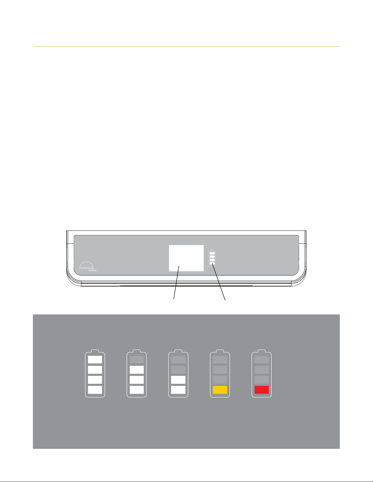
The Battery Level Indicator (BLI) indicates the status of the T7’s power system. Several modes are displayed through the BLI.
• Standby Mode: All of the T7’s BLI lights are dark.
• Charging Mode: The BLI is depicted with four bars representing increments of battery charge level. If the battery is
less than 25% charged, the lowest bar will be blinking. If the battery is less than 50% charged, the lowest bar will be
solid and the second bar will be blinking. If the battery is less than 75% charged, the lowest two bars will be solid and
the second to highest bar will be blinking. If the battery is less than 100% charged, the lower three bars will be solid and
the top bar will be blinking.
• Charging Finished Mode: When input power is removed from the cart by unplugging from the wall, all four lights
are illuminated.
• Discharge Mode: The BLI displays how much battery capacity is left. At full battery capacity, all lights are illuminated.
As power is drawn from the battery, the lights extinguish sequentially from top to bottom, counting down capacity in
approximately 25% increments. Once the cart reaches the 25% level, the bottom LED turns to yellow. Once the battery
level reaches the critically low battery level, the bottom LED turns red and an optional beeping sounds. This is an indication
that approximately one minute of run time remains and the system should be plugged in immediately to prevent loss of
operation and /or data.
36
Battery level indication
100 %
Steady white lights
Steady white lights Steady white lights Steady yellow light Blinking red light
Touch Screen Display Battery Level Indicator
75% 50% 25 %
Optional beeping sound.
IT can turn it on and
off on IT screen.
<15 %
Page 38
7.4 S HUTDOWN SWITCH
The T7’s shutdown switch is located underneath the work surface, in the rear left-hand corner as ou are facing the cart.
Its main function is to limit power to the customer accessory outlets. It also turns the touch screen display off shown
on page # 36. This function is useful when initially configuring the added cart equipment (hardware, monitor, etc.) or to
reduce discharge of internal battery source when the cart will not be used for an extended period of time. ( Note: Setting
the shutdown switch to the off position also disables the Optional Remote Power Management. See Section 7.5, Optional
Remote Power Management).
7.5 O PTIONAL REMOTE POWER MANAGEMENT
Available as a factory option, a Remote Power Management program allows cart users to monitor the operation and status
of the onboard power system. With software provided by Humanscale—installed on a host computer and connected to the
power system via USB cable—users can view remaining battery run time, charge status, remaining charge time, and other
key performance indicators:
• Battery Model: Model number of specific battery module installed in cart: 480 w/hr, 720 w/hr or LiOn
• Battery Type: Sealed Lead Acid (Pb) or LiIon ( Li)
• Battery Install Date: Date on which new or replacement battery module was installed (useful to determine
approximate service life remaining)
• Battery Life Remaining: Amount of charge capacity, or run-time percentage, of the battery module, based on real-time
system load
• Battery Voltage: Present voltage level of the battery source
• Battery Temperature: Average case temperature of the batteries in the system
• Charge Status: Indicator of the present charge mode
• Charge Cycles: Number of cumulative battery charge/discharge cycles
• Charge Current: DC amps presently being delivered to recharge the batteries
• Discharge Current: DC amps presently being delivered from the batteries to the cart power system
Remote Power Management Interface
37
Page 39

8.0 ADJUSTING THE T7
Proper ergonomics can help reduce and prevent workplace injuries by
lessening the physical demands on the worker. Ergonomically designed
products, such as the T7 point-of-care technology cart, take into account the
wide range of people who will use the product, so that everyone, regardless
of their stature, can use the product easily and comfortably—essentially,
allowing the job to fit the worker instead of the other way around.
The T7’s 20” (50.8 cm) height range ensures comfortable accommodation
for both seated and standing workers.
8.1 T IPS ON ADJUSTING THE T7
TIPS
• Push the cart with arms placed close to
body. Do not pull the cart. Pushing utilizes
your own body weight, while pulling causes
undue stress and can result in ankle and
knee injury.
• Keep the
equipment organized. A well-maintained
cart will be easier to move and an organized
cart will be less susceptible to accidents.
cart well maintained and the cart
38
Page 40
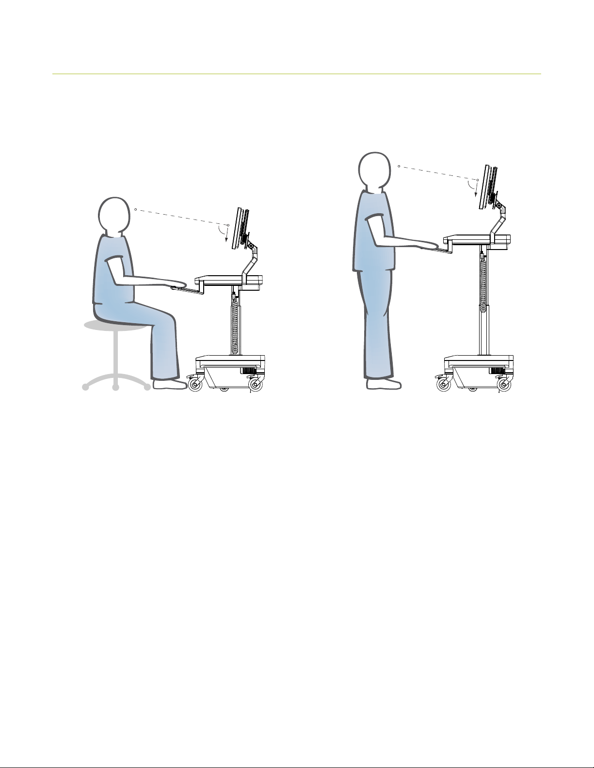
8.2 ERGONOMIC MONITOR POSITIONING
Position the monitor so that the top of the screen is slightly below eye level.
90˚
90˚
39
Page 41
9.0 TROUBLESHOOTING AND FREQUENTLY ASKED QUESTIONS
Why am I not getting power to the computer or monitor?
First, be certain that all power cords are properly connected to the outlet mounts and that all equipment power switches
are turned on, meaning the computer, monitor, and any other accessories that will be plugged into the internal AC Power
Source Triple Tap. Also, the correct switches on the T7 must be engaged to get power to the Internal AC Power Source
Triple Tap. Be sure that the Battery Level Indicator (BLI) is not showing a red or blinking red light. If so, the T7 needs to be
charged.
How do I know if the T7 requires charging?
Check the Battery Level Indicator (BLI) on the front of the T7. If the red light is illuminated or blinking red, the cart needs
to be charged. The T7 may be charged at any time, but immediate charging is recommended if the BLI is showing orange
or red. (See Section 7.3 Battery Level Indicator, page 35.)
When should I charge the system?
When the T7 first arrives, charge it to full capacity. (See Section 7.1 Initial System Startup and Shutdown, page 34.) After
the proper initial charge, you may recharge at any time, but charging is recommended when the BLI is showing red.
Can I access the power supply to repair it?
No. Do not attempt to access or repair the power supply. Tampering with the power supply could damage the T7, void the
warranty, and/or cause personal injury. You must contact Humanscale so that a trained technician can service the cart.
Can I use an extension cord with the T7?
For safety reasons, using an extension cord with the T7 is not recommended. This applies to all outlets and power cords
connecting to and from the cart. The T7 comes with a coiled AC cord that should provide necessary extension.
What should I do if the power goes out while I’m recharging the T7?
Unplug the T7 from the AC outlet. When power is restored, continue recharging.
If the T7 gets wet, what should I do?
Unplug it and power it off immediately, wipe off any excess liquid, and allow the T7 to dry before using it again.
What happens when the battery runs out while the cart is adjusting?
When power is restored, access the IT (see page 21) screen and calibrate the cart. To calibrate, push the calibrate button
and release. The calibrate button will flash yellow and the T7 cart will start to move downward. Once T7 cart reaches a
height of 4’ 11” sitting, the calibration is finished.
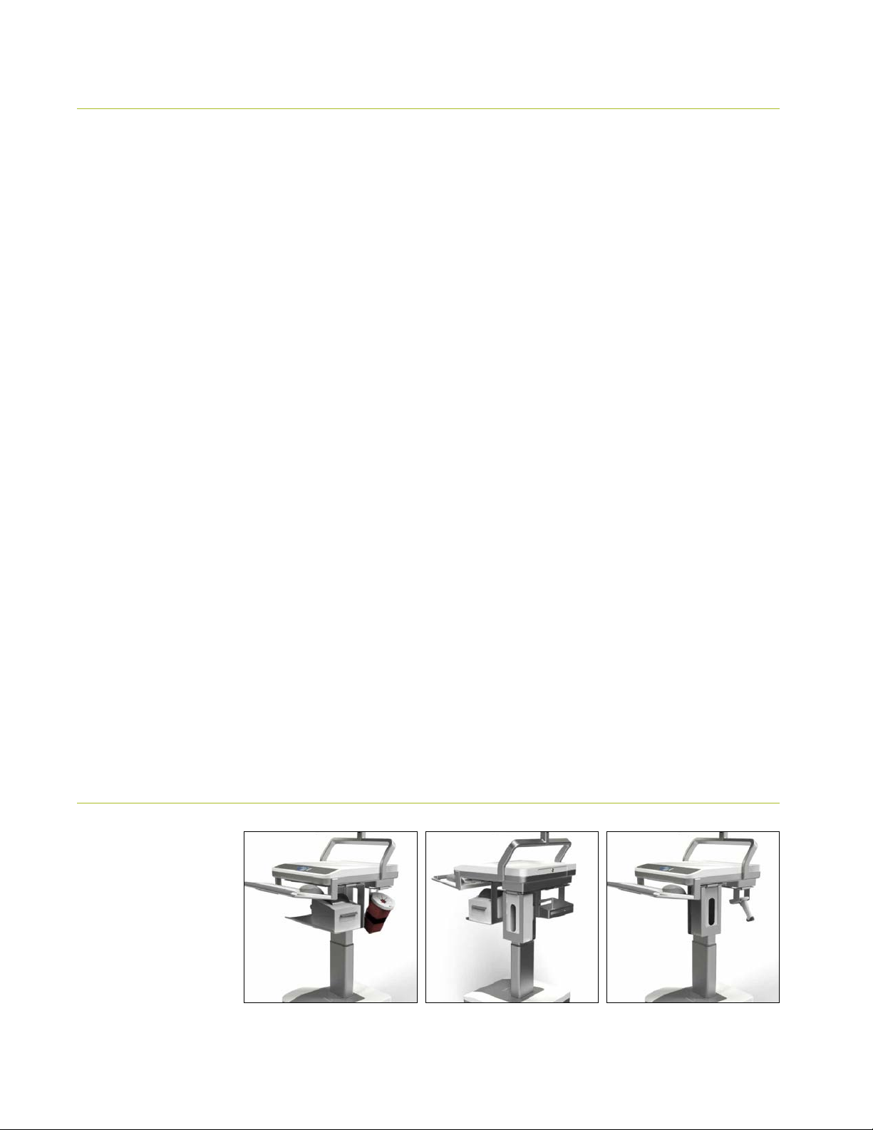
10.0 ACCESSORIES
T7 Accessories:
• Scanner Bracket
• Basket
• Printer Shelf
• Sharps Container
• Glove Box holder
40
Page 42
TECHNICAL INFORMATION
41
Page 43
11. 0 MAINTENANCE AND CLEANING
To ensure optimal performance of the T7 Point-of-Care Technology Cart,
please observe the following maintenance and cleaning schedule monthly.
11.1 CART MAINTENANCE
SERVICE AND REPLACEMENT
Do not attempt to service or replace any part of the T7 unless directed to do so through Humanscaleapproved documentation (i.e., this User Manual or other instructions). Only Humanscale or a
Humanscale-certified entity may service or replace the cart components. If any component on the
cart is missing or damaged, the cart must not be used. Contact Humanscale Customer Service
immediately to request service.
CABLES
All cables aside from the AC power cord, keyboard USB, mouse USB, and PC/laptop power cords
are routed internally within the T7. Be sure that cords are clean and not broken or cut at any location.
Be sure that they are solidly connected to their respective outlet.
CASTERS
Check casters periodically to ensure that they are clean and free of any debris that could prevent
smooth operation. Avoid moving the T7 across uneven, dirty, or damaged surfaces.
CUSTOMER EQUIPMENT
Be sure equipment is balanced and mounted securely to the T7. Repositioning the cart components
too high or too low may create an unstable condition, leading to equipment damage or personal
injury. Note: Failure to adhere to these guidelines may void Product Warranty. (See Section 13.0
Warranty, page 47.)
BATTERY MAINTENANCE
All battery maintenance must be performed by a trained technician. Before performing all battery
maintenance, put the T7 in Standby Mode (see Section 7.3 Battery Level Indicator, page 35), unplug
the power cord from the wall, and disconnect the ground (black) lead from the battery. Visually
inspect the cart’s battery monthly. If a battery bulges severely on charge, it is an indication of a
blocked valve or an overcharge situation. Please contact Humanscale if you notice any
battery defects.
Cable connections must be cleaned and tightened as part of your scheduled maintenance. Many
battery problems are caused by dirty or loose terminal connections. First, remove the battery from
the T7 prior to cleaning. The battery terminals should be cleaned using three tablespoons of baking
soda in a pint of water.
The battery supplied with the T7 is sealed. Never attempt to open the battery or add any water or
other fluids.
42
Page 44
11. 2 C ART CLEANING
The following procedures are not guaranteed to control infection. Consult the hospital infection-control administrator or
epidemiologist regarding specific cleaning procedures and processes.
Always unplug the T7 and power it down before cleaning.
All exterior surfaces, excluding electrical components, will withstand cleaning by most commonly
used, diluted, non-abrasive solutions such as quaternary ammonium compounds, ammonia, enzyme
cleaners, bleach and alcohol solutions.
Pen and permanent and dry-erase marker can be removed with 91% isopropyl alcohol and a soft cloth.
Iodine stains can be removed with commonly used cleaners and a soft cloth.
Never clean the T7 with steel wool or other abrasive materials that will damage the surface finish.
Do not rub a wet or damp cloth over any electrical components. Do not immerse
the
T7 or its components in liquid or allow liquids to flow into internal compartments
or over any electrical components. Thoroughly dry all surfaces after cleaning.
Do not use flammable cleaners on
power and equipment.
It is recommended that any cleaning solution be tested on a small, inconspicuous area
to ensure surface is not harmed.
T7 surfaces due to close proximity of electrical
43
Page 45
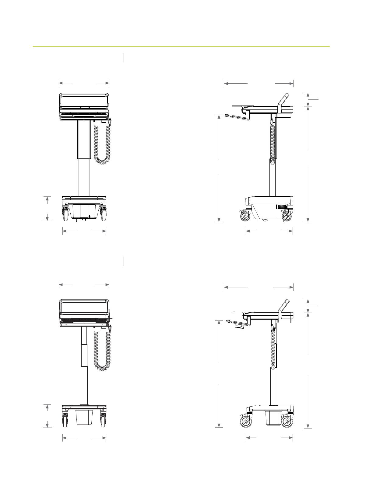
12.0 DIMENSIONS AND RANGE OF ADJUSTMENTS
T7 POWERED
10.2”
26 cm
20.6”
52.32 cm
18.1”
46 cm
Weight
132 lbs.
59.87 kg.
23.6 - 43.7”
60 - 111 cm
28.1”
71.35 cm
5.625”
14.3 cm
27.2 - 47.2”
69 - 120 cm
19.5”
49.5 cm
T7 NON-POWERED
20.6”
52.32 cm
9.2”
23.2 cm
Weight
66 lbs.
29.93 kg.
23.6 - 43.7”
60 - 111 cm
28.1”
71.35 cm
5.625”
14.3 cm
30.5 - 47”
77.4 - 119.5 cm
44
18.1”
46 cm
19.5”
49.5 cm
Page 46
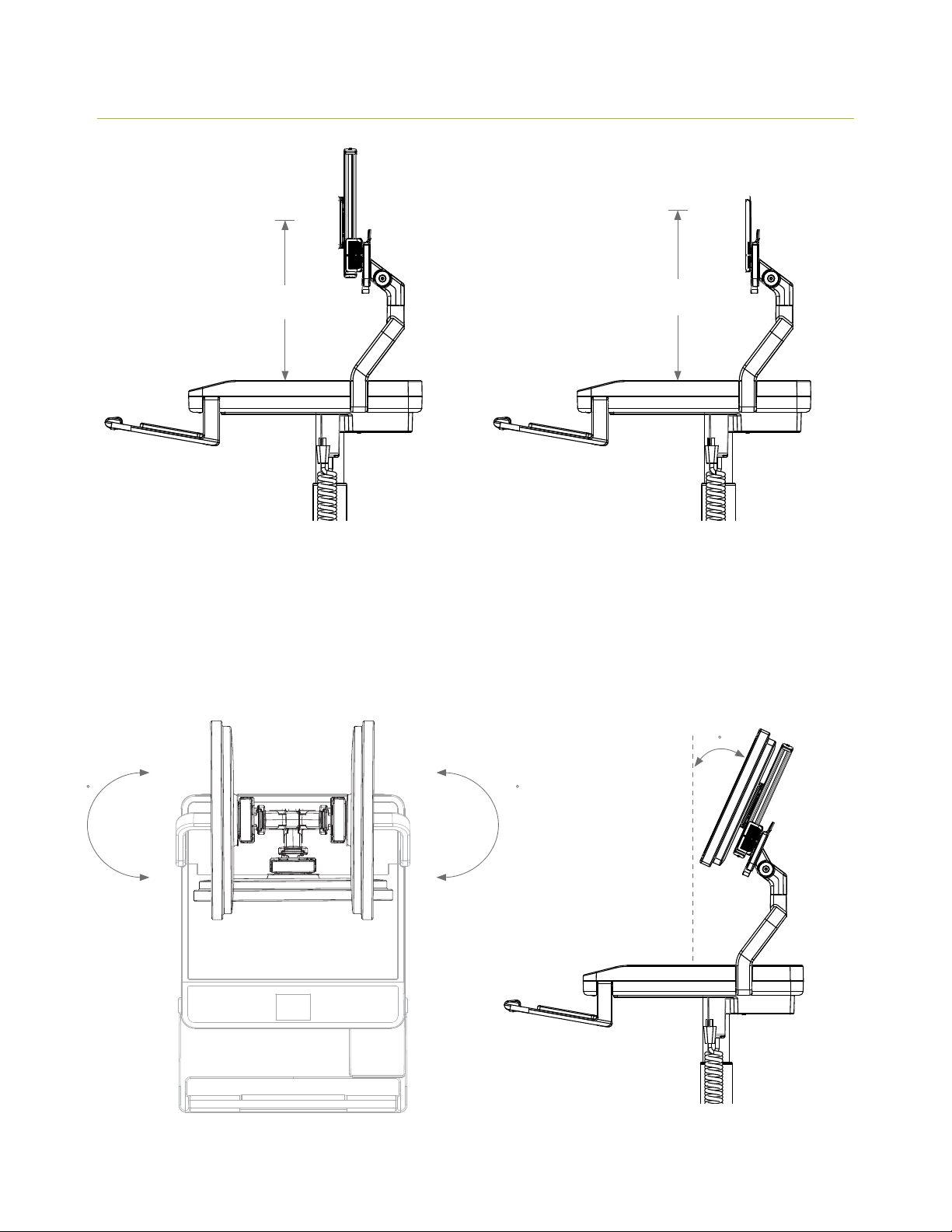
12 .1 MONITOR ADJUSTMENT RANGE
Adjustable Mount
5.1-16.9”
13-43 cm
Fixed Mount
x”
x cm
14.9”
37.7 cm
Rotation Range
90 90
Tilt Range
15
45
Page 47
13.0 RADIATED EMISSIONS
The use of accessories and cables, other than those specified or sold
by the manufacturer of the equipment as replacement parts for internal
components, may result in increased emissions or decreased immunity of
the equipment.
The T7 Point-of-Care Technology Cart may cause interference when used
adjacent to or stacked with electrical equipment outside the system and
could affect normal operation of said equipment. Do not stack additional
electrical equipment on top of the work surface enclosure.
13 .1 RECOMMENDED SEPA RATED DISTANCES
The T7 is intended for use in the electromagnetic environment specified below in which radiated disturbances are
controlled. The T7 user can help prevent electromagnetic interference by maintaining a minimum distance between
portable and mobile RF Communications Equipment and the T7 as recommended below, according to the maximum
output power of the communications equipment.
For transmitters rated at a maximum output power not listed above, the recommended separation distance (D) in meters
(M ) can be determined using the equation applicable to the frequency of the transmitter, where ( P) is the maximum
output power rating of the transmitter in watts (W ) according to the transmitter manufacturer.
Max Output Power
(W)
0.01 0.12 0 .12 0.23
0.1 0.38 0.38 0.73
1 1.2 1.2 2.3
10 3.8 3.8 7.3
100 12 12 23
Separation
(M)
150 kHz to 80 MHz
D = 1.2 (SartP)
Separation
(M)
to 800 MHz
81
D = 1.2 (Sart P)
Separation
(M)
801 MHz to 2.5 GHz
D = 1.2 (Sart P)
Equipment and Systems that are NOT Life-Supporting
Note 1: At 80 MHz, the higher frequency range applies.
Note 2: These guidelines may not apply in all situations. Electromagnetic propagation is affected by absorption and reflection from structures, objects
and people.
46
Page 48

13.2 GUIDANCE AND MANUFACTURER’S DECLARATION—EMISSIONS
The T7 is intended for use in the electromagnetic environment specified below. The T7 user should ensure that it is used in
such an environment.
Emiss ions Te st
RF Emissions CISPR 11 Group 1
RF Emissions CISPR 11 Class A or B
Harmonics IEC 61000-3-2 Class A or B
Flicker IEC 61000 -3-3 N/A
Compliance Level Electromagnetic
Environment—Guidance
T7 uses RF energy only for its
The
internal functions. Therefore, its
RF emissions are very low and are
not likely to cause any interference
with nearby electronic equipment.
120V AC 60 Hz input power.
T7 is suitable for use in all
The
establishments, including
domestic, and those directly
connected to the public low
voltage power supply network
that supplies buildings used
for domestic purposes.
All Equipment and Systems
47
Page 49

13.3 GUIDANCE AND MANUFACTURER’S DECLARATION—IMMUNITY
The T7 is intended for use in the electromagnetic environment specified below. The T7 user should ensure that it is used in
such an environment.
The T7 has been certified to the safety and EMC requirements of IEC 60601-1, 2nd and 3rd edition.
Immunit y Tes t IEC 60601 Test Level Compliance Level Electromagnetic
Environment—Guidance
ESD IEC
61000-4-2
EFT IEC
61000-4-4
Surge IEC
61000-4-5
Voltage Dips/
Dropout IEC
61000-4-11
±6 kV Contact
±8 kV Air
±2 kV Mains
±1 kV I/Os
1 kV Differential
±2 kV Common
> 95% Dip Cycle for .05 Cycle
60% Dip Cycle for 5 Cycles
30% Dip for 25 Cycles
95% Dip for 5 seconds
±6 kV Contact
±8 kV Air
±2 kV Mains
I/Os N/A
±1 kV Differential
±2 kV Common
> 95% Dip Cycle for .05 Cycle
60% Dip Cycle for 5 Cycles
30% Dip for 25 Cycles
95% Dip for 5 seconds
Floors should be wood,
concrete or ceramic tile. If
floors are synthetic, the
r/h should be at least 30%.
Mains power quality
should be that of a
typical commercial or
hospital environment.
Mains power quality
should be that of a
typical commercial or
hospital environment.
Mains power quality
should be that of a typical
commercial or hospital
environment. If the user of
T7 requires continued
the
operation during power
mains interruptions, it is
recommended that the
T7 be powered from an
uninterruptable power
supply or battery.
Power Frequency
50/60 Hz
Magnetic Field
IEC 61000-4-8
All Equipment and Systems
48
3 A/m 3 A/m Power frequency magnetic
fields should be that
of a typical commercial or
hospital environment.
Page 50

Immunit y Tes t IEC 60601 Test
Level
Compliance Level Electromagnetic
Environment—Guidance
Conducted
RF IEC
61000-4-6
Radiated RF IEC
61000-4-3
3
Vrms 150 kHz
to 80 MHz
3 V/m 80 MHz to
2.5 GHz
Equipment and Systems that are
(3 ) Vrms
3) V/m
(
not Life-Supporting
Do not dispose of the T7 or any associated components at the end of service life. Contact Humanscale
for disposal instructions
Note 1: At 80 MHz, the higher frequency range applies.
Note 2: These guidelines may not apply in all situations. Electromagnetic propagation is affected by absorption and reflection
from structures, objects, and people.
a. Field strengths from fi xed transmitters, such as base stations for radio (cellular/cordless) telephones and land mobile radios,
amateur radio, AM and FM radio broadcast, and TV broadcast cannot be predicted theoretically with accuracy. To assess the
electromagnetic environment in the presence of fixed RF transmitters, an electromagnetic site survey should be considered. If the
measurement field strength in the location in which the T7 is used exceeds the applicable RF compliance level above, the T7 should
be o bse r ved to ve rif y norm al operat ions . Abnor mal per for man ce measures may be necessar y, such as reo rie nting or relocat ing the T7.
b. Over the frequency range 150 kHz to 80 MHz, field strengths should be less than 3 Vrms.
49
Page 51

14.0 SHIPPING AND OPERATING ENVIRONMENT
Please note these recommended environmental conditions for the
transportation and operation of the T7 Point-of-Care Technology Cart.
Shipping, storing or using the T7 in extreme conditions outside the
recommended range may adversely affect the performance of the T7 and
may void the warranty.
14 .1 SHIPPING ENVIRONMENT
Storage/Shipping Temperature Range 23º to 95º F / –5º to 35º C
Storage/Shipping Relative Humidity Range 10% to 80%
14.2 OPERATING ENVIRONMENT
Operating Temperature Range 0 ºC to 40ºC
Operating Relative Humidity 0% to 95%
Operating Elevation 0 to 3,000 meters
15.0 SYSTEM MESSAGES
Type Message Action to be taken
System Clear Perimeter Before
Proceeding
Error "Cart Was Stopped! Please
Select User Height"
Ensure cart perimeter cleared before selecting
"OK" to begin lifter calibration process
Cart height stopped in range between sitting
and standing zone: User must select "OK" and
then re-enter height setting desired
50
Page 52

System "Pause" Touch screen to pause movement if desired
during lifter travel
System "Please Enter User Height" Preset Screen - User selects height to be
entered for 1 of 6 presets
Error "Cart Adjustment Was
Interrupted! Clear Perimeter
and Continue"
Error "Cart Adjustment Was
Interrupted!" Clear Perimeter
and Enter User's Height."
Collision Detection - User must ensure that
collision hazard is removed and then select
"RESUME"
Collision Detection - User must ensure that
collision hazard is removed, select "OK" and
then re-enter desired height
System "PowerTrack Enabled" None
16.0 WARRANTY
For warranty and terms and conditions, please visit www.humanscale.com
© 2012 Humanscale. All rights reserved. Patent pending. Humanscale is a registered trademark of Humanscale Corporation. Reproduction of this
material in whole or part for any purpose other than that authorized by Humanscale is prohibited.
HSI T70513
51
 Loading...