

Page 1
V7
Installation
Instructions
Page 2
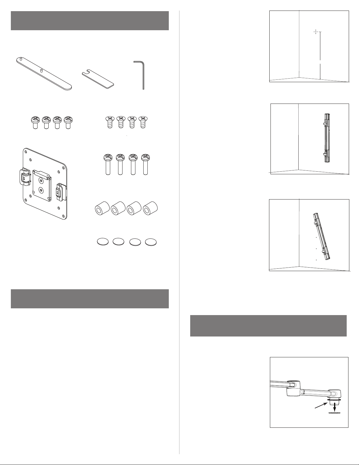
INSTALLATION HARDWARE
Hardware Kit
b. Choose the desired
hole location for top
fastener, ideally 66” to
68” off the floor. Drill hole
and install appropriate
fastener.
66 - 68 “
Two-Prong Spanner Wrench
4 Standard VESA Bracket Screws
VESA Bracket
Additional hardware required:
Electric drill with 3” driver or driver extension
10 mm Flat Wrench
4 Keyboard Tray Screws
4 Extended VESA Bracket Screws
4 Plastic Spacers
4 3M Dual Lock Coins
Hex Key (2mm)
c. Hold Track against the
wall and fasten using the
appropriate fastener in
pre-drilled hole.
d. Use level to ensure
Track is perfectly plumb.
Mark the other 4
mounting hole locations.
e. Pre-drill the 4 remaining
mounting holes and install
appropriate fastener.
f. Fasten Track with
appropriate fasteners in
the remaining mounting
holes. Be sure to tighten
fully so fastener heads do
not protrude beyond track
1b
1d
1e
STEP 1: MOUNT TRACK TO WALL
a. For new construction, Track can be mounted to a wall
stud or mounting board. For existing construction, test
the wall by drilling a pilot hole to determine what fasteners
are most suitable for installation. Be sure to drill the pilot
hole in a spot that will be covered by the Track.
Recommendations:
For wood – Use 2” #10 flat-head wood screws.
For metal – Use 2 ¾” #10 flat-head self-tapping screws.
For drywall – Use 3/16” flat-head toggle bolts
(Hilti brand recommended).
Note: For exact fastener requirements, please refer to
OSHPD specifications (OPA-2238-07) included.
surface.
STEP 2: ATTACH MONITOR ARM
TO TRACK
a. Unscrew aluminum nut from
the bottom of Aluminum
Bushing (A).
A
2a
Page 3
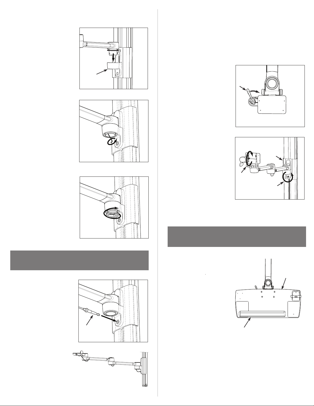
b. Slide Aluminum Bushing into
top Slider Assembly (B),
ensuring set screw is aligned
with the small notch in the
Note: Release Handle will
not function properly unless
cable is evenly distributed
throughout the arm.
mount. Be sure Plastic Washer
sits between Monitor Arm and
Track Mount.
c. Using the ball end of the
2mm Hex Key (provided),
tighten Set Screw located
inside Aluminum Bushing.
Note: Set Screw does not
need to be fully tightened,
but should prevent Bushing
from rotating.
d. Reattach the aluminum nut
to the bottom of Aluminum
Bushing. Tighten using
Two-Prong Spanner Wrench
d. Try Release Handle (B) to
B
2b
ensure it functions properly.
Arm should move freely when
the Release Handle is
B
triggered.
Note: If necessary, adjust
cable tension using adjustment under the Keyboard
3d
Mount (C) and at the point
where it connects to Track
(D). Additional cable tension
D
adjustment can be achieved
2c
by tightening the screw on
Mount (E).
C
E
3d note
(provided).
STEP 3: ATTACH KEYBOARD ARM
TO TRACK
a. Repeat Step 2 to attach
Keyboard Arm.
b. Insert Threaded Screw
attached to the length of
Cable (A) into the hole in Slider
Assembly. Tighten fully.
c. Distribute cable evenly
throughout Keyboard Arm,
STEP 4: ATTACH KEYBOARD TRAY
2d
a. Place Keyboard Tray (A) on
top of Keyboard Arm and align
holes.
b. Fasten Keyboard Tray to
Keyboard Arm using 4
Keyboard Tray Installation
A
3b
Screws.
c. Snap Palm Rest (B) into the
holes on Keyboard Tray.
TO KEYBOARD ARM
A
B
ensuring equal amounts of
slack are available at each joint.
3c
Page 4
STEP 5: ATTACH MONITOR TO
MONITOR ARM
CABLE MANAGEMENT
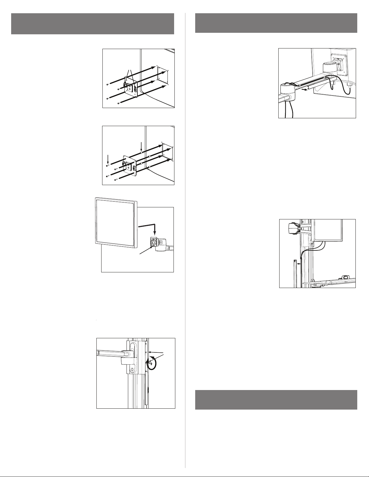
a. Attach appropriate VESA
bracket to Monitor.
i. Place VESA Bracket in
position on back of
Monitor with Lips (A) on
the left and right. Attach
using 4 Standard VESA
Bracket Screws.
ii. If mounting space for
75mm VESA bracket is
inset into back of Monitor,
place 4 Plastic Spacers (B)
between VESA Bracket
and Monitor. Align hole
pattern. Using 4 Extended
VESA Bracket Screws (C),
attach through Spacers.
a. Route monitor cables
A
starting from Monitor going
to Track.
i. Remove gray arm covers
from one side of Monitor
Arm. Insert monitor cables
B
Arm’s front link. Thread
cables behind the cable management tabs to hold them
into the groove of Monitor
a
in place. Check that Monitor has enough slack to rotate,
C
then replace front arm cover.
ii. Route cables down through Monitor Arm’s center joint.
Repeat above step to route cables through Monitor Arm’s
rear link. Check that Monitor Arm has enough slack to
bend and move, then replace rear arm cover.
b. Route monitor cables
b. Slide VESA Bracket into
Ball Joint (D) until it clicks.
c. Monitor should ride up and
down effortlessly and stay in
position when set. If Monitor
tends to drift up or down,
tension may be adjusted via
the two center screws (E)
under the white plastic slide
on each side of Mount. Using
Hex Key located under
Keyboard Tray, loosen screws
to increase tension and
tighten screws to decrease
tension.
Note: Do NOT adjust top or
bottom screw.
through Track.
i. Remove cable
D
management covers on
one side of Track. Insert
5b
monitor cables into the
groove of Track. Replace
b
cable management covers.
Note: Where monitor cables exit
Track should be determined by the
location of your CPU and nearest outlet.
E
c. Repeat above steps to route
keyboard and mouse cables.
ATTACH KEYBOARD TO KEYBOARD TRAY
5c
a. Place 4 3M Dual Lock Coins on the underside of Keyboard.
b. Once attached, remove the film from the exposed
sides of Dual Lock Coins and attach to Keyboard Tray.
 Loading...