

Page 1

Assembly Instructions
When using a Humanscale work surface
with pre-drilled metal inserts
Parts Required
A. (1) Float Table Base
B. (2) Float Wing Brackets
C. (2) Float Feet
D. (1) Mounted or Removable Spring Tension Adjuster
E. (1) Mounted Spring Tension Adjuster Plastic Housing
F. (12) M6 Short Machine Screws
G. (4) M5 Long Machine Screws
H. (4) M6 Short Flat Head Machine Screws
I. (8) M8 Long Machine Screws
J. (4) M5 Short Machine Screws
K. (1) Safety Leg Pin
A
C
E
Tools Required
Extension Hex Drive
5/32 ” Hex Drive
3/16 ” Hex Drive
3 mm Hex Drive
Power Drill
B
K
Hardware Bag
F
I
G H
D
J
1
Page 2

Assembly Instructions for Humanscale pre-drilled work surfaces
1
Installing the Float Wing Brackets
a. Remove the two machine screws on each end of the center beam (fig. A)
Important: The machine screws that should be removed are the ones on the same side as the spring tension
min – max scale
b. Install each Bracket on its respective table side by screwing the two machine screws through the Wing Bracket and
back into the center beam (fig. B)
c. Install the (4) M6 Short Flat Head Machine Screws through the top of the Wing Brackets and into the Float Base (fig. C)
A
2
Installing the Float Feet
B C
a. Turn the Float Base upside down so that the center beam
is on the floor while the Float Feet are being installed
b. Install the Feet by lining up each of the four holes over the
top of the legs
Important: The longer section of the Feet must be on the
same side as the spring tension min – max scale
c. Use (4) M8 Long Machine Screws to secure each Foot to
the Base frame (fig. D)
3
Place the work surface face down on a soft surface
to avoid scratching it
D
4
Turn the Float Base upside down (if it is not already) and
place onto the underside of the work surface
a. Ensure that all mounting holes on the Float Base line up
with the pre-drilled metal inserts on the underside of the
work surface
b. With the Float Base in position, use the (12) M6 Short
Machine Screws to secure the Float Base to the
work surface (fig. E)
E
2
Page 3

5
Installing the Release Paddle
a. Line up the Release Paddle with the corresponding pre-drilled metal
inserts on the underside of the work surface
b. With the Release Paddle in position, use the (4) M5 Long Machine
Screws to secure the Release Paddle to the work surface (fig. F)
Important: Do not over tighten the Release Paddle
6
Installing the Mounted Spring Tension Adjuster
(if you did not order your Float with this option, please proceed to step 7)
a. Take the Mounted Spring Tension Adjuster and locate the metal shaft
into the hex spigot on the center beam
b. Line up the Mounted Spring Tension Adjuster with the corresponding
pre-drilled metal inserts on the underside of the work surface
c. With the Mounted Spring Tension Adjuster in position, use the (4) M5
Short Machine Screws to secure it to the work surface
d. Take the Mounted Spring Tension Adjuster Plastic Housing, place and
snap into position over the (4) M5 Short Machine Screws that were
installed in step 6c (fig. G)
F
G
7
Carefully turn the Float back over and into position so that it is
ready to use
8
Remove the Safety Leg Pin on the right side (to the right of the
min – max scale) by removing the red tape and pulling it out
H
(this is used for shipping purposes only) (fig. H)
9
You will now be able to operate your new Float by gently squeezing the Release Paddle and supporting the
work surface as you raise and lower it
3
Page 4
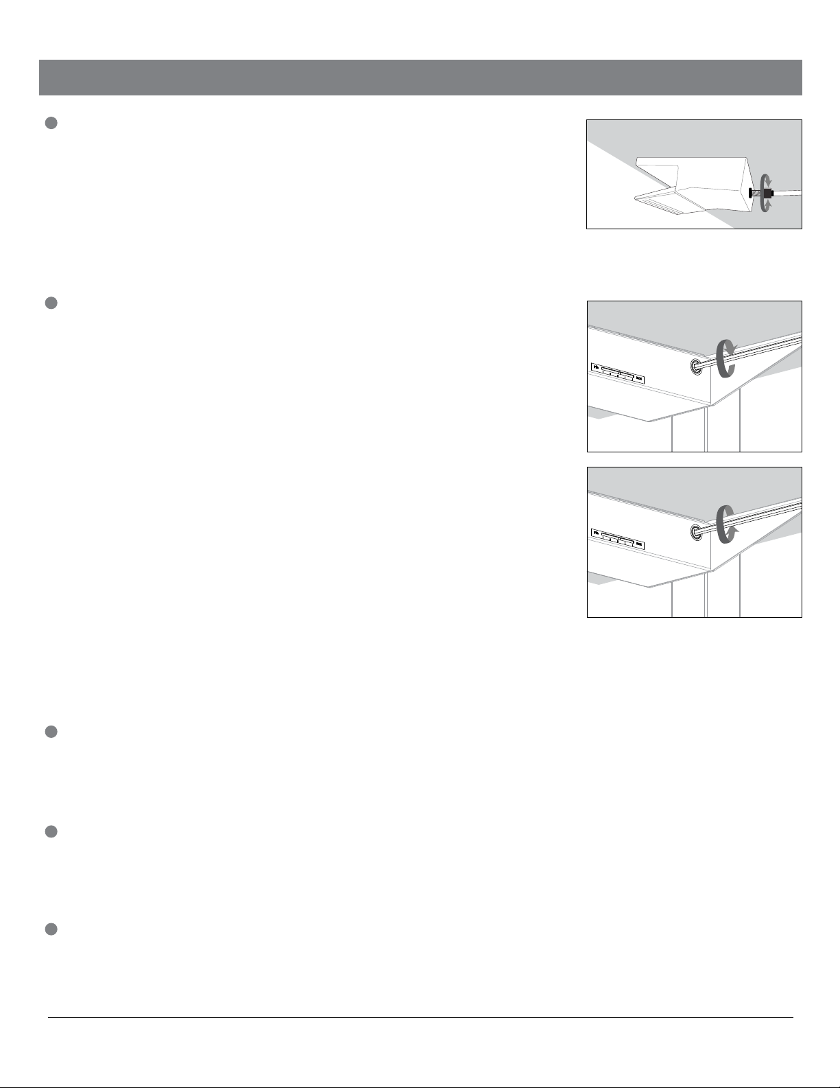
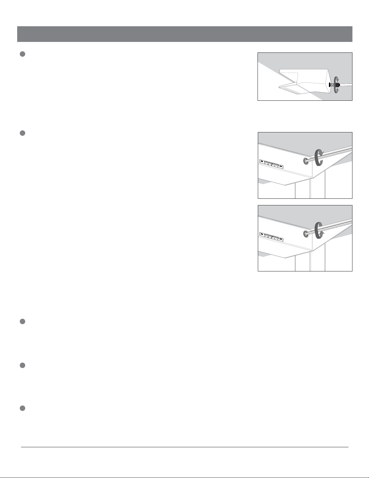
Adjusting Float
1
If you are finding it difficult to raise and lower your Float, please check the barrel
adjuster behind the back of the Release Paddle (fig. A). The barrel adjuster
needs to be adjusted to increase the tension in the Release Paddle which will
allow for the Float to easily raise and lower. To make the required adjustment,
simply turn the barrel adjuster counterclockwise until you have between ¾” and
½” of metal thread showing. You will now find that the Release Paddle will
engage better and allow for the Float to be raised and lowered
Important: Please be aware that your newly purchased Float will hold a maximum weight of 130 lbs. Please contact
Customer Service if you would like to find out more information about our Float heavy duty kit that will increase the
maximum weight loading from 130 lbs to 160 lbs.
2
Adding Weight to the Work Surface (fig. B)
As you begin to add more weight to the work surface, it will become more
difficult to raise and lower the table. The following steps explain how to adjust
your Float to make it easier to raise and lower:
1. Squeeze the Release Paddle and raise the work surface to its
maximum height (fully extended)
2. If using the Removable Spring Tension Adjuster, insert it into the hex
spigot on the center beam to the right of the min – max scale
3. Using either the Removable or Mounted Spring Tension Adjuster,
slowly begin to increase the tension by turning the Adjuster clockwise
4. You will start to see the red mark on the min – max scale move from the
min mark towards the max mark
5. Once you have adjusted your Float, bring the work surface back down
and try raising and lowering it a few times until it fluidly adjusts
6. If you need to make further adjustments, raise the Float to its
maximum height and follow these steps again
A
B
C
Removing Weight from the Work Surface (fig. C)
As you begin to remove weight from your work surface, you will notice that
Float will raise quickly and be difficult to lower. Simply follow the above instructions about adding weight to the work surface, but instead of turning the Adjuster clockwise, you will need to turn the Adjuster counterclockwise to release the
spring tension in the Float.
3
Float sits on four glides which can be adjusted to level the work surface, if the
floor is not level. These can be independently adjusted.
Troubleshooting Float
1
If you are finding it difficult to raise and lower your Float, please check the barrel adjuster behind the back of the
Release Paddle (fig. A). The barrel adjuster needs to be adjusted to increase the tension in the Release Paddle which
will allow for the Float to raise and lower. To make the required adjustment, simply turn the barrel adjuster counterclockwise until you have between ¾” and ½” of metal thread showing. You will now find that the Release Paddle will
engage better and allow for the Float to be raised and lowered
2
If your Float is adjusted so that the min – max mark is at the ¾” position on the scale and the Float is still very difficult
to raise and lower, please contact Customer Service who will help you order a heavy duty Float kit that will allow for the
weight limit to be increased from 130 lbs to 160 lbs. This heavy duty kit will make the table easier to adjust with the
additional weight.
Customer Service - 800 400 0625 www.humanscale.com
4
HSFI0713
Page 5
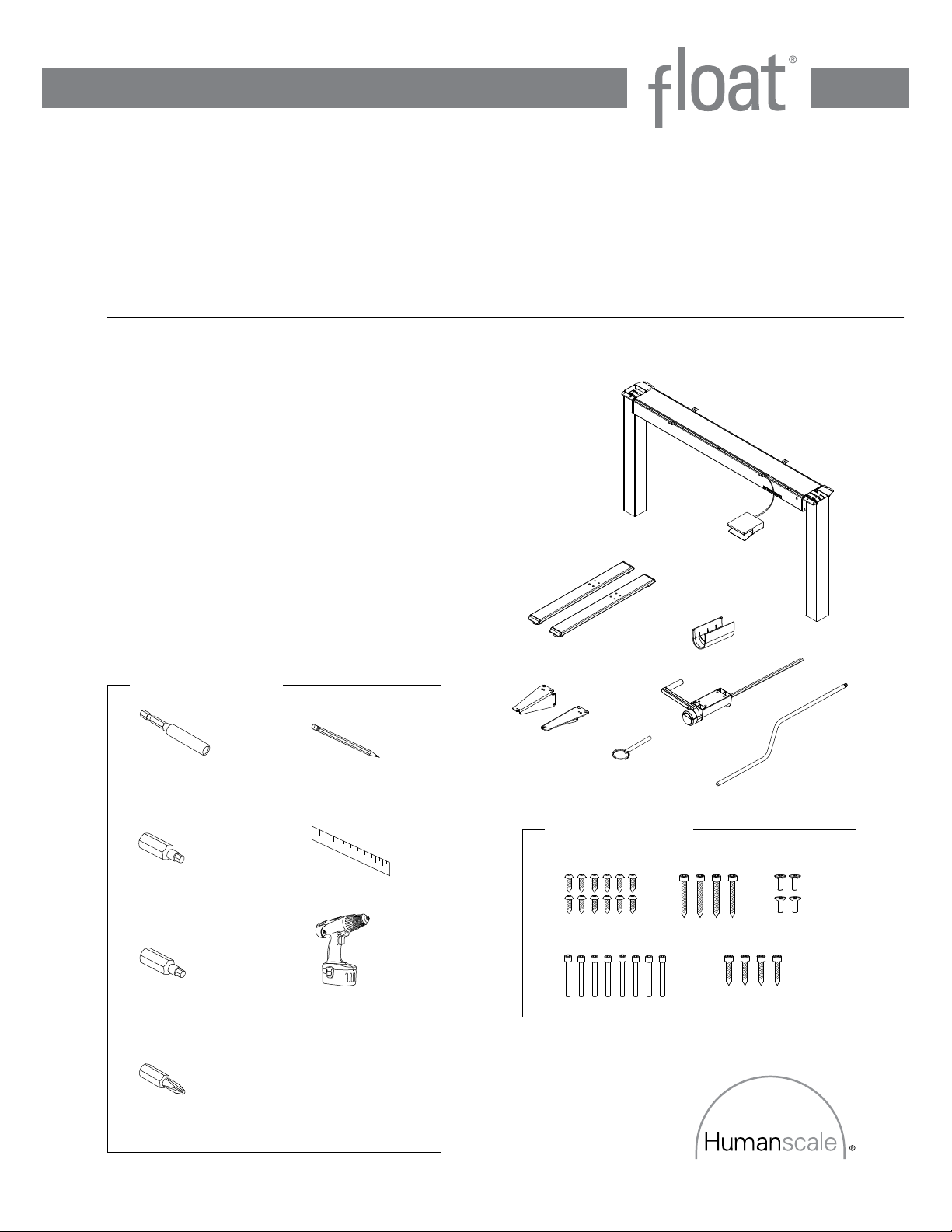
Assembly Instructions
When using your own work surface that is
at least 3/4 “ thick and has no pre-drilled holes
Parts Required
A. (1) Float Table Base
B. (2) Float Wing Brackets
C. (2) Float Feet
D. (1) Mounted or Removable Spring Tension Adjuster
E. (1) Mounted Spring Tension Adjuster Plastic Housing
F. (12) ¾” Wood Screws
G. (4) 1 ½” Wood Screws
H. (4) M6 Short Flat Head Machine Screws
I. (8) M8 Long Machine Screws
J. (4) ½” Wood Screws
K. (1) Safety Leg Pin
A
C
E
Tools Required
Extension Hex Drive
5/32 ” Hex Drive
3/16 ” Hex Drive
#2 Phillips Screwdriver
Pencil
Ruler
Power Drill
B
K
Hardware Bag
F
I
G H
D
J
5
Page 6
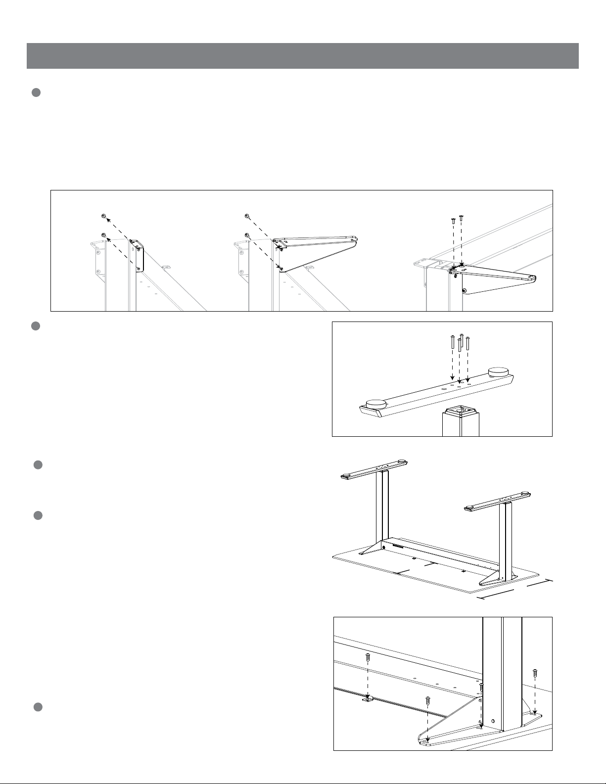
Assembly Instructions for work surfaces with no pre-drilled holes
1
Installing the Float Wing Brackets
a. Remove the two machine screws on each end of the center beam (fig. A)
Important: The machine screws that should be removed are the ones on the same side as the spring tension
min – max scale
b. Install each Bracket on its respective table side by screwing the two machine screws through the Wing Bracket and
back into the center beam (fig. B)
c. Install the (4) M6 Short Flat Head Machine Screws through the top of the Wing Brackets and into the Float Base (fig. C)
A
2
Installing the Float Feet
B C
a. Turn the Float Base upside down so that the center beam
is on the floor while the Float Feet are being installed
b. Install the Feet by lining up each of the four holes over the
top of the legs
Important: The longer section of the Feet must be on the
same side as the spring tension min – max scale
c. Use (4) M8 Long Machine Screws to secure each Foot to
the Base frame (fig. D)
3
Place the work surface face down on a soft surface
to avoid scratching it
D
4
Turn the Float Base upside down (if it is not already) and
place onto the underside of the work surface
a. Please ensure that the Float Base is centered so that
there is equal distance from the edge of the work surface
on either side
For Float tables that have 30” deep surfaces: Measure and
mark 16.5” from the front edge of the work surface to the
front edge of the center beam (the same edge that the spring
min – max scale is positioned on) (example shown)
For Float tables that have 24” deep surfaces: Measure and
mark 13.5” from the front edge of the work surface to the
front edge of the center beam (the same edge that the spring
min – max scale is positioned on)
5
With the Float Base in position according to your
markings, use the (12) ¾” Wood Screws to secure the
Float Base to the work surface. Use the smaller holes
provided on the Float Base for this (fig. E)
16.5”
30”
E
6
Page 7
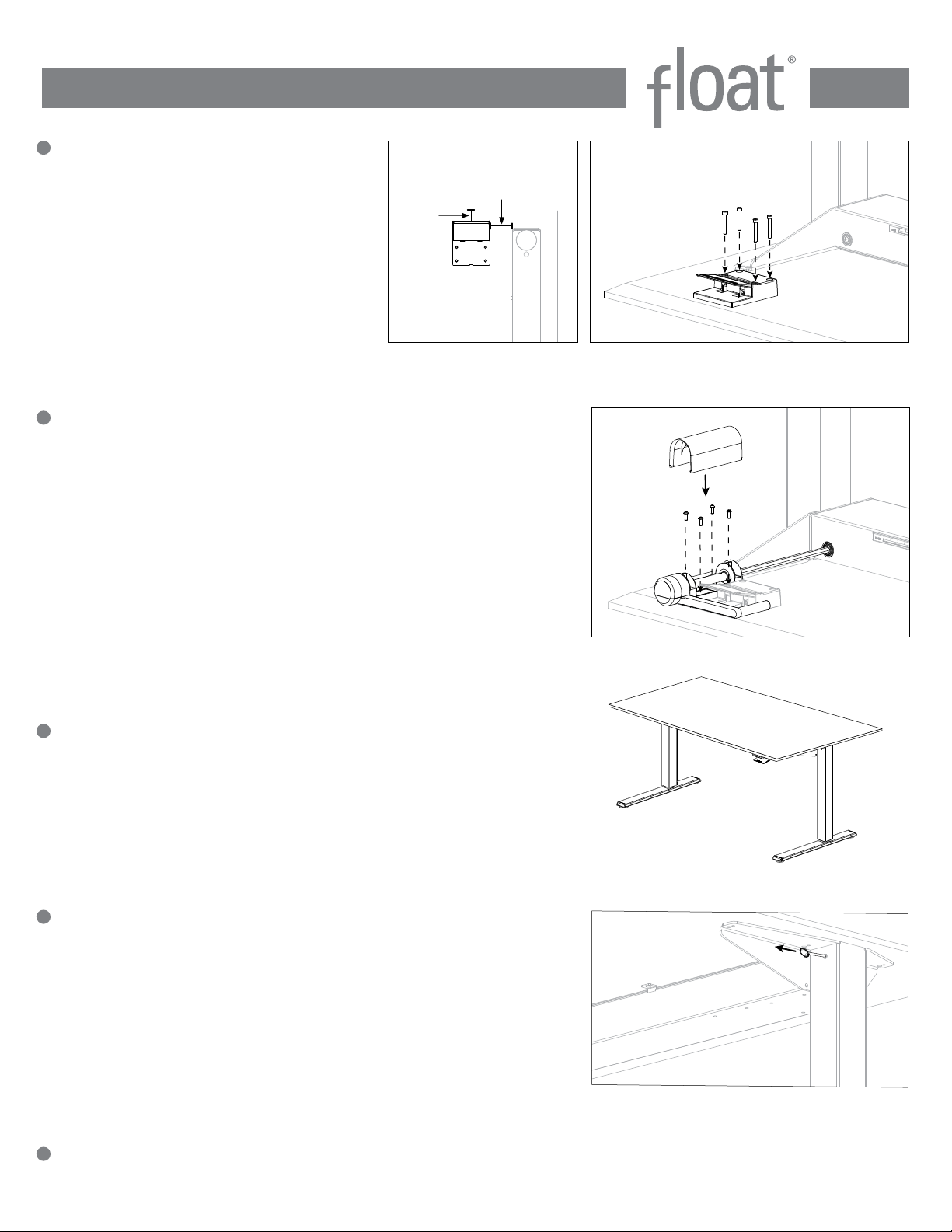
6
Installing the Release Paddle
F G
a. Place the Float Release Paddle 1”
from the front edge of the work
surface and 2¼” from the inside
edge of the Wing Bracket (fig. F)
1”
2.25”
b Use the (4) 1½” Wood Screws to
secure the Release Paddle to the
work surface. (fig. G)
Important: Do not over tighten the
Release Paddle
7
Installing the Mounted Spring Tension Adjuster
(if you did not order your Float with this option, please proceed to step 8)
a. Take the Mounted Spring Tension Adjuster and locate the metal shaft
into the hex spigot in the center beam
b. Position the Mounted Spring Tension Adjuster in line with the
installed Release Paddle. Use the (4) ½” Wood Screws to secure
down to the work surface
c. Take the Mounted Spring Tension Adjuster Plastic Housing, place
and snap into position over the (4) ½” Wood Screws that were
installed in step 7b (fig. H)
H
8
Carefully turn the Float back over and into position so that it is
ready to use
9
Remove the Safety Leg Pin on the right side (to the right of the
min – max scale) by removing the red tape and pulling it out
I
(this is used for shipping purposes only) (fig. I)
10
You will now be able to operate your new Float by gently squeezing the Release Paddle and supporting the
work surface as you raise and lower it
7
Page 8
Adjusting Float
1
If you are finding it difficult to raise and lower your Float, please check the barrel
adjuster behind the back of the Release Paddle (fig. A). The barrel adjuster
needs to be adjusted to increase the tension in the Release Paddle which will
allow for the Float to easily raise and lower. To make the required adjustment,
simply turn the barrel adjuster counterclockwise until you have between ¾” and
½” of metal thread showing. You will now find that the Release Paddle will
engage better and allow for the Float to be raised and lowered
Important: Please be aware that your newly purchased Float will hold a maximum weight of 130 lbs. Please contact
Customer Service if you would like to find out more information about our Float heavy duty kit that will increase the
maximum weight loading from 130 lbs to 160 lbs.
2
Adding Weight to the Work Surface (fig. B)
As you begin to add more weight to the work surface, it will become more
difficult to raise and lower the table. The following steps explain how to adjust
your Float to make it easier to raise and lower:
1. Squeeze the Release Paddle and raise the work surface to its
maximum height (fully extended)
2. If using the Removable Spring Tension Adjuster, insert it into the hex
spigot on the center beam to the right of the min – max scale
3. Using either the Removable or Mounted Spring Tension Adjuster,
slowly begin to increase the tension by turning the Adjuster clockwise
4. You will start to see the red mark on the min – max scale move from the
min mark towards the max mark
5. Once you have adjusted your Float, bring the work surface back down
and try raising and lowering it a few times until it fluidly adjusts
6. If you need to make further adjustments, raise the Float to its
maximum height and follow these steps again
A
B
C
Removing Weight from the Work Surface (fig. C)
As you begin to remove weight from your work surface, you will notice that
Float will raise quickly and be difficult to lower. Simply follow the above instructions about adding weight to the work surface, but instead of turning the Adjuster clockwise, you will need to turn the Adjuster counterclockwise to release the
spring tension in the Float.
3
Float sits on four glides which can be adjusted to level the work surface, if the
floor is not level. These can be independently adjusted.
Troubleshooting Float
1
If you are finding it difficult to raise and lower your Float, please check the barrel adjuster behind the back of the
Release Paddle (fig. A). The barrel adjuster needs to be adjusted to increase the tension in the Release Paddle which
will allow for the Float to raise and lower. To make the required adjustment, simply turn the barrel adjuster counterclockwise until you have between ¾” and ½” of metal thread showing. You will now find that the Release Paddle will
engage better and allow for the Float to be raised and lowered
2
If your Float is adjusted so that the min – max mark is at the ¾” position on the scale and the Float is still very difficult
to raise and lower, please contact Customer Service who will help you order a heavy duty Float kit that will allow for the
weight limit to be increased from 130 lbs to 160 lbs. This heavy duty kit will make the table easier to adjust with the
additional weight.
Customer Service - 800 400 0625 www.humanscale.com
8
HSFI0713
 Loading...