

Humanscale Extended Ergo Lift User Manual
Extended Ergo Lift Assembly Instructions
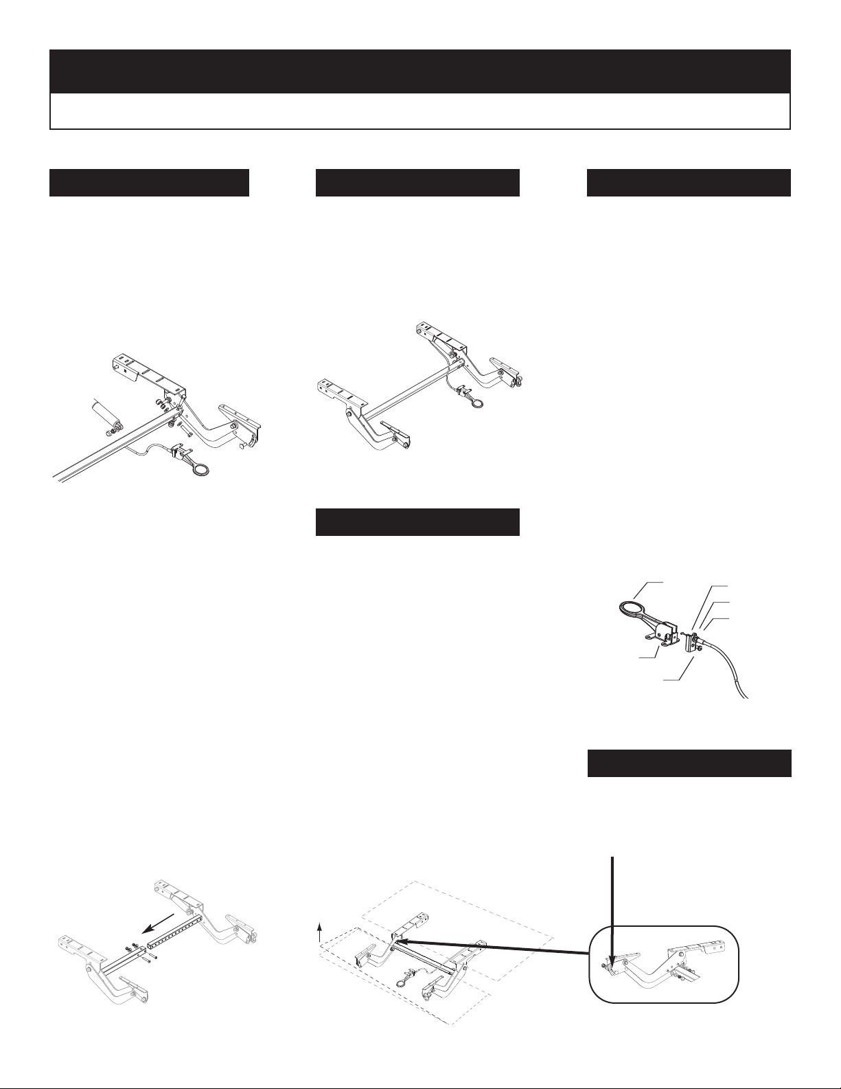
Lift
.38
Cable Mount
Hex Nut
Washer
Screw
Cable
Bracket
Release
Lever
Hardware Bag Components: Hex Head Bolt (2) • Hex Locknut (4) • Flat Washer (6) • Cap (4) • Screw (20)
Assemble the Cross Tube
1.
Fixed Width Models
Slide cross tube over square
mounting stud on R.H. Assembly
Insert (2) hex bolts with (2) flat
washers through cross tube and
stud. Assemble (2) flat washers
and (2) hex locknuts. Tighten
fasteners to 200 in-lbs or until tube
is flattened against mounting stud.
Note: Improper tightening of hardware may result in excess keyboard movement. Install opposite
end of cross tube over (2) studs on
L.H. Assembly and fasten with (2)
flat washers and (2) hex locknuts.
DO NOT TIGHTEN AT THIS TIME!
Adjustable Width Models
Follow same procedure used for
mounting fixed width R.H. & L.H.
Arm assemblies except as follows:
o adjust for desir
T
ed width remove & save hardware used to
position two cross halves for shipping. Slide assembly either in or
out to final width and replace hard-
e. Tighten hardware between
war
tube halves to 200 in-lbs. or until
play between tubes is removed.
Install Brackets to Table
2.
Attach assembled Ergo Lift brack-
.
work surfaces. Attach release lever
ets to underside of fr
ont and rear
to underside of front work surface
with (4) scr
ews provided.
Adjust Cables
4.
(if necessar
y)
Cable is pre-set at factory.
Adjustment should only be made if
elease lever does not lock key-
r
board in position (Cable to tight) or
if lever does not release keyboard.
(Cable to loose)
A. To adjust the cable free play,
remove the cable mount from the
cable bracket by removing screw.
B. Loosen the cable hex nut.
C. Adjust the position of the cable
mount by screwing on or off the
desired amount.
D. Tighten the cable hex nut.
E. Make sure the cable end is
installed in the release lever.
3. Level Keyboard (if necessary)
Reinstall the cable mount onto the
handle assembly.
Left side of tube is designed to
provide leveling capability.
A. Activate release lever so front
surface right hand side is approximately level with rear surface.
Release lever.
B. Manually raise the left hand
side of front work surface approximately 1/2” above the right hand
side, hold in this position and tighten (2) nuts to 200 in-lbs.
Re-adjust if not level. (Use
C.
5. Tilt Tension (if necessary)
dimension less then 1/2” if left
hand side is too high.)
Tilt tension nut is pre-set at the factory, but can be adjusted by tight-
D. Install caps over hex nuts.
ening or loosening the hex locknut
as shown.
Rev. 6-26-06
 Loading...