

Page 1
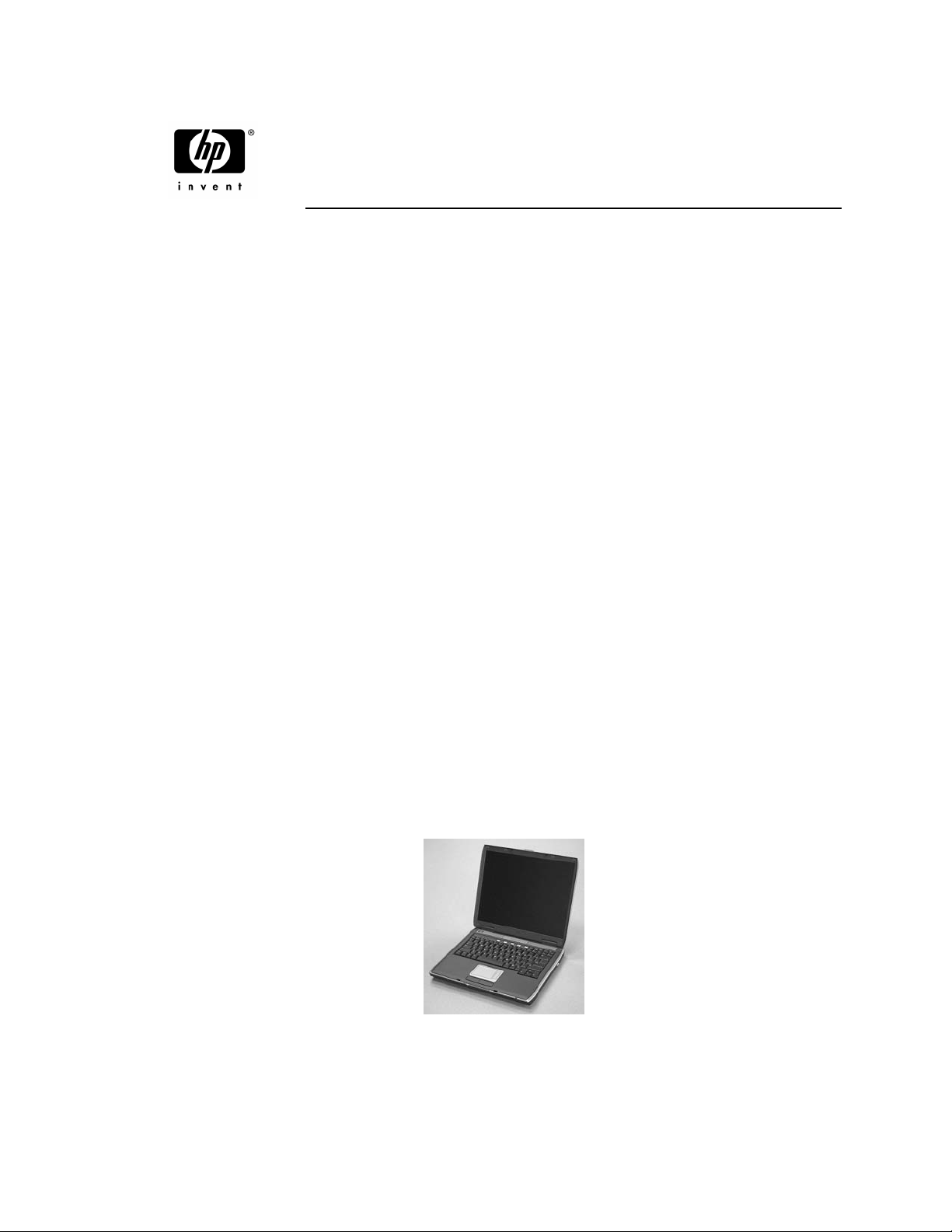
HP Pavilion ze5600 Notebook PC
HP Pavilion ze5500 Notebook PC
HP Pavilion ze5400 Notebook PC
HP Pavilion ze5300 Notebook PC
HP Pavilion ze5200 Notebook PC
HP Pavilion ze4600 Notebook PC
HP Pavilion ze4500 Notebook PC
HP Pavilion ze4400 Notebook PC
HP Pavilion ze4300 Notebook PC
HP Pavilion ze4200 Notebook PC
HP Pavilion ze4100 Notebook PC
HP nx9010 Notebook PC
HP nx9008 Notebook PC
HP nx9005 Notebook PC
HP nx9000 Notebook PC
Compaq Evo Notebook N1050v Series
Compaq Evo Notebook N1010v Series
Compaq Presario 2500 Series Mobile PC
Compaq Presario 2100 Series Mobile PC
Compaq Presario 1100 Series Mobile PC
Technology Code KE
Service Manual
Service Manual i
Page 2

Please check out our eBay auctions for more great
deals on Factory Service Manuals:
Page 3

© Copyright 2003, 2004 Hewlett-Packard Development Company, L.P.
Microsoft and Windows are U.S. registered trademarks of Microsoft Corporation. Intel ,Celeron, and
Pentium are trademarks or registered trademarks of Intel Corporation or its subsidiaries in the United States
and other countries.
The information contained herein is subject to change without notice. The only warranties for HP products
and services are set forth in the express warranty statements accompanying such products and services.
Nothing herein should be construed as constituting an additional warranty. HP shall not be liable for
technical or editorial errors or omissions contained herein.
Service Manual
Third Edition February 2004
First Edition January 2003
Document Part Number: 319733-003
ii Service Manual
Page 4

Contents
Introduction..................................................................................................................... vii
Product Information...................................................................................................... 1-1
Features ................................................................................................................................................ 1-8
Operation............................................................................................................................................ 1-14
Specifications ..................................................................................................................................... 1-18
Internal Design................................................................................................................................... 1-24
Removal and Replacement............................................................................................ 2-1
Disassembly Flowchart ........................................................................................................................ 2-3
Removing the Battery .......................................................................................................................... 2-4
Removing an SDRAM Module............................................................................................................ 2-5
Removing the Wireless LAN Mini PCI Card ...................................................................................... 2-7
Removing the Hard Disk Drive............................................................................................................ 2-9
Recovering the Factory Software....................................................................................................... 2-11
Replacing Small Parts ........................................................................................................................ 2-12
Removing the Keyboard Cover.......................................................................................................... 2-13
Removing the Speaker Assembly ...................................................................................................... 2-15
Removing the Keyboard .................................................................................................................... 2-16
Removing the Switchboard PCA ....................................................................................................... 2-19
Removing the CD/DVD Drive........................................................................................................... 2-20
Removing the Display Assembly....................................................................................................... 2-23
Removing the Top Case..................................................................................................................... 2-26
Removing the Floppy Drive............................................................................................................... 2-32
Removing the Infrared (I/R) PCA...................................................................................................... 2-36
Removing the Audio PCA ................................................................................................................. 2-38
Removing the Heat Sink (with Fan)................................................................................................... 2-40
Removing the CPU Module............................................................................................................... 2-44
Removing the RJ11/1394 Connector Module.................................................................................... 2-48
Removing the Motherboard ............................................................................................................... 2-50
Replacing Components on a Bottom Case......................................................................................... 2-59
Repairing the BIOS IC....................................................................................................................... 2-61
Removing Other Components............................................................................................................ 2-63
Troubleshooting and Diagnostics ................................................................................. 3-1
Support by Authorized Service Providers............................................................................................ 3-2
Troubleshooting ................................................................................................................................... 3-3
Diagnostic Tools ................................................................................................................................ 3-18
Replaceable Parts........................................................................................................... 4-1
Reference Information .................................................................................................. 5-1
Password Removal Policy.................................................................................................................... 5-2
Hewlett-Packard Display Quality Statement........................................................................................ 5-3
Service Notes and Obsolete Parts ........................................................................................................ 5-5
Service Manual iii
Page 5

Figures
Figure 1-1. Front View................................................................................................................................ 1-8
Figure 1-2. Back View ................................................................................................................................ 1-9
Figure 1-3. Bottom View........................................................................................................................... 1-10
Figure 1-4. Front View.............................................................................................................................. 1-11
Figure 1-5. Back View .............................................................................................................................. 1-12
Figure 1-6. Bottom View........................................................................................................................... 1-13
Figure 1-7. Resetting the Notebook .......................................................................................................... 1-17
Figure 1-8. Replaceable Module Diagram ................................................................................................ 1-24
Figure 2-1. Disassembly Flow..................................................................................................................... 2-3
Figure 2-2. Removing the Battery............................................................................................................... 2-4
Figure 2-3. Removing an SDRAM Module ................................................................................................ 2-5
Figure 2-4. Removing an SDRAM Module ................................................................................................ 2-6
Figure 2-5. Removing the Mini PCI Card................................................................................................... 2-7
Figure 2-6. Removing the Mini PCI Card................................................................................................... 2-8
Figure 2-7. Removing the Hard Disk Drive ................................................................................................ 2-9
Figure 2-8. Removing the Hard Disk Drive Tray...................................................................................... 2-10
Figure 2-9. Removing the Keyboard Cover .............................................................................................. 2-14
Figure 2-10. Disconnecting the Speaker Cable ......................................................................................... 2-14
Figure 2-11. Removing the Speaker Assembly......................................................................................... 2-15
Figure 2-12. Removing the Keyboard....................................................................................................... 2-17
Figure 2-13. Removing the Switchboard PCA.......................................................................................... 2-18
Figure 2-14. Removing the Switchboard PCA.......................................................................................... 2-19
Figure 2-15. Removing the CD/DVD Drive ............................................................................................. 2-21
Figure 2-16. Removing the CD/DVD Drive ............................................................................................. 2-22
Figure 2-17. Removing the Display Assembly ......................................................................................... 2-24
Figure 2-18. Removing the Top Case........................................................................................................ 2-27
Figure 2-19. Removing the Top Case Screws........................................................................................... 2-29
Figure 2-20. Removing the Top Case Screws........................................................................................... 2-30
Figure 2-21. Removing the Top Case........................................................................................................ 2-31
Figure 2-22. Removing the Floppy Drive ................................................................................................. 2-33
Figure 2-23. Removing the Floppy Drive ................................................................................................. 2-35
Figure 2-24. Removing the I/R PCA......................................................................................................... 2-37
Figure 2-25. Removing the Audio PCA.................................................................................................... 2-39
Figure 2-26. Removing the Heat Sink (with Fan) ..................................................................................... 2-41
Figure 2-27. Removing the Heat Sink (with Fan) ..................................................................................... 2-43
Figure 2-28. Removing the CPU Module.................................................................................................. 2-45
Figure 2-29. Removing the CPU Module.................................................................................................. 2-47
Figure 2-30. Removing the RJ11/1394 Connector Module ...................................................................... 2-49
Figure 2-31. Removing the Motherboard.................................................................................................. 2-51
Figure 2-32. Removing the Hard Disk Drive Guide .................................................................................2-53
Figure 2-33. Disconnecting the Motherboard Cables................................................................................ 2-54
Figure 2-34. Removing the Motherboard.................................................................................................. 2-56
Figure 2-35. Example of Serial Number Label ......................................................................................... 2-59
Figure 2-36. Replacing the Antennas ........................................................................................................ 2-60
Figure 2-37. Removing a PCMCIA Door ................................................................................................. 2-60
Figure 2-38. Boot-Block Jumper............................................................................................................... 2-62
Figure 3-1. Basic Troubleshooting Steps .................................................................................................... 3-3
Figure 4-1. Exploded View ......................................................................................................................... 4-2
Figure 4-2. Exploded View ......................................................................................................................... 4-3
iv Service Manual
Page 6

Tables
Table 1-1. Product Comparisons................................................................................................................. 1-1
Table 1-2. Activating Power Modes ......................................................................................................... 1-14
Table 1-3. Main Status Lights (front of notebook) ................................................................................... 1-15
Table 1-4. Keyboard Status Lights............................................................................................................ 1-15
Table 1-5. Fn Hot Keys............................................................................................................................. 1-16
Table 1-6. Specifications........................................................................................................................... 1-18
Table 1-7. Accessories .............................................................................................................................. 1-22
Table 1-8. Functional Structure Description ............................................................................................. 1-25
Table 2-1. Removal Cross-Reference ......................................................................................................... 2-1
Table 2-2. Required Equipment .................................................................................................................. 2-2
Table 2-3. Recommended Screw Torque Values........................................................................................ 2-2
Table 2-4. Replacing Small Parts.............................................................................................................. 2-12
Table 2-5. Removing Components............................................................................................................ 2-63
Table 3-1. ASP Support Options................................................................................................................. 3-2
Table 3-2. Scope of Diagnostic Tools......................................................................................................... 3-7
Table 3-3. Troubleshooting Suggestions..................................................................................................... 3-8
Table 3-4. POST Terminal-Error Beep Codes .......................................................................................... 3-20
Table 3-5. POST Messages ....................................................................................................................... 3-24
Table 3-6. Sycard PCCtest Commands ..................................................................................................... 3-26
Table 3-7. BIOS Setup Menus and Parameters......................................................................................... 3-28
Table 4-1. Replaceable Parts....................................................................................................................... 4-4
Table 4-2. Accessory Replaceable Parts ................................................................................................... 4-11
Table 4-3. Part Number Reference............................................................................................................ 4-12
Table 5-1. LCD Guidelines ......................................................................................................................... 5-4
Service Manual v
Page 7
Introduction
This manual provides reference information for servicing the HP Pavilion ze5600, ze5500, ze5400,
ze5300, ze5200, ze4600, ze4500, ze4400, ze4300, ze4200, and ze4100 Notebook PCs, HP nx9010,
nx9008, nx9005, and nx9000 Notebook PCs, Compaq Evo Notebook 1050v and 1010v Series, and
Compaq Presario 2500, 2100, and 1100 Series Mobile PCs. These notebook models use technology code
KE. This manual is for use by authorized service personnel while installing, servicing, and repairing these
products.
The manual is designed as a self-paced guide that will train you to install, configure, and repair these
notebooks. The manual is self-contained, so you can follow it even without having equipment available.
The following table lists other sources of information about the notebook computers and related products.
Source Address or Number Comments
HP Notebook Web site
Compaq Notebook Web site
HP Business Support Web site
HP Asia Pacific Channel Support
Centre for DPSP Partners
America Online Keyword: HP Call (800) 827-6364
CompuServe GO HP Call (800) 524-3388
HP Support Assist
CD-ROM
(801) 431-1587 Outside US and Canada.
Microsoft® Windows® manual Information about
Microsoft Web site
http://www.hp.com/notebooks
http://welcome.hp.com/country/us/eng/prodserv/
notebooks_tabletpcs.html
http://www.hp.com/go/bizsupport
http://www.hp.com.au/
(800) 457-1762 U.S. and Canada.
http://www.microsoft.com/
Restricted to DPSP
Partners only.
for membership within the
US.
for membership within
the U.S.
Windows operating
system.
Information and updates
for Windows operating
systems.
Service Manual vii
Page 8
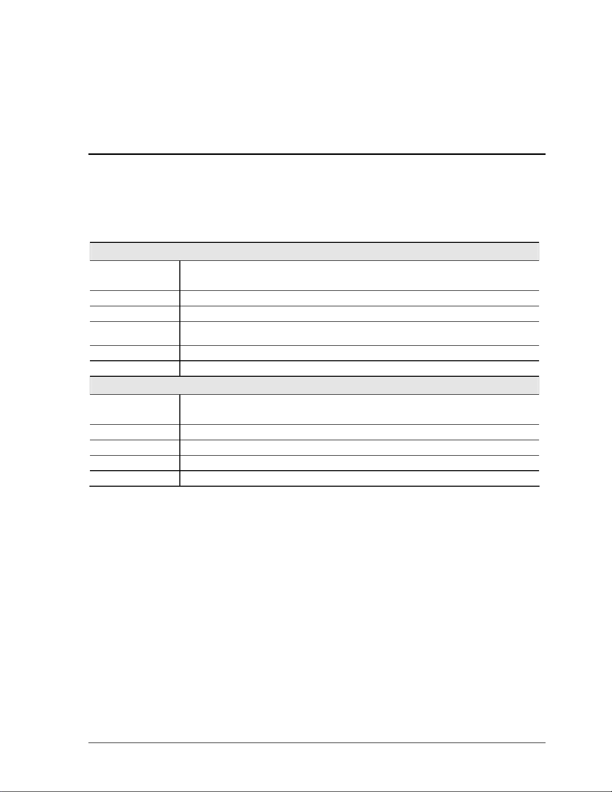
1
Product Information
The following list of HP and Compaq notebook products is current at the time of publication but is subject
to change.
HP Pavilion ze5600
Processor Intel® Celeron® (2.6-, 2.8-GHz)
Mobile Intel Pentium® 4 (2.4-, 2.66-, 2.8-, and 3.06-GHz)
Memory Up to 1 GB (1024 MB) SDRAM using 512-MB modules. At least 256 MB SDRAM preinstalled.
Display 15.0-inch XGA (1024 × 768) or SXGA+ (1024 × 768) active-matrix TFT
Video ATI Mobility Radeon graphics accelerator with 16, 32, or 64 MB UMA graphics memory, 4x AGP graphics
capability
Operating System Microsoft® Windows® XP Professional or Windows XP Home preinstalled
Power States On, Standby, Hibernate, Off
HP Pavilion ze5500
Processor Intel Celeron (2.6-GHz)
Mobile Intel Pentium 4 (2.4-, 2.66-, 2.8-, and 3.06-GHz)
Memory Up to 1 GB (1024 MB) SDRAM using 512-MB modules. At least 256 MB SDRAM preinstalled.
Display 15.0-inch XGA (1024 × 768) or SXGA+ (1400 × 1050) or 14.1-inch XGA (1024 × 768) active-matrix TFT
Operating System Windows XP Professional or Windows XP Home preinstalled
Power States On, Standby, Hibernate, Off
Table 1-1. Product Comparisons
Service Manual Product Information 1-1
Page 9

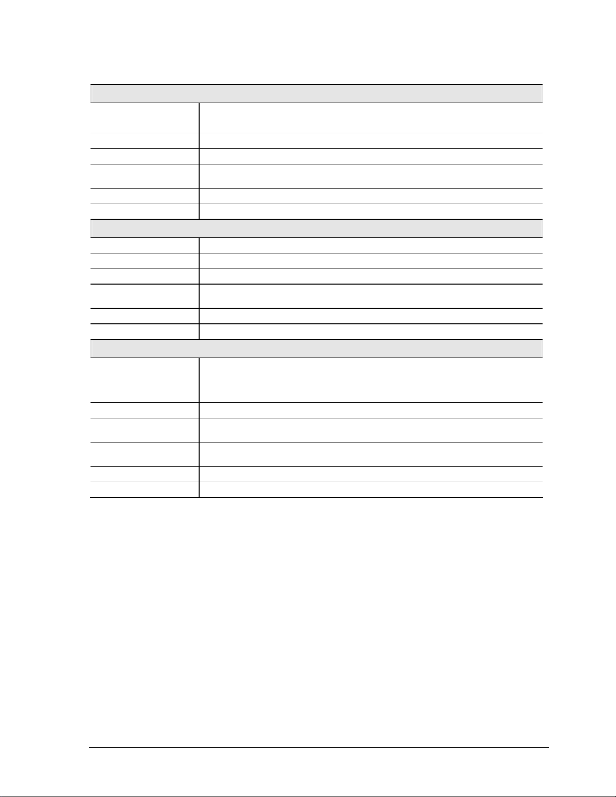
HP Pavilion ze5400 and ze5300
Processor Intel Pentium 4 (2.4-, 2.53-, 2.66-, and 2.8-GHz)
Mobile Intel Pentium 4 (2.4-, 2.66-, 2.8-, and 3.06-GHz)
Memory Up to 1 GB (1024 MB) SDRAM using 512-MB modules. At least 256 MB SDRAM preinstalled.
Display 15.0-inch XGA (1024 × 768) or SXGA+ (1400 × 1050) or 14.1-inch XGA (1024 × 768) active-
Video ATI Mobility Radeon graphics accelerator with 16, 32, or 64 MB UMA graphics memory, 4x AGP
Operating System Windows XP Professional or Windows XP Home preinstalled
Power States On, Standby, Hibernate, Off
HP Pavilion ze5200
Processor Mobile Intel Pentium 4 (2.4-, 2.53-, 2.66-, and 2.8-GHz)
Memory Up to 1 GB (1024 MB) SDRAM using 512-MB modules. At least 256 MB SDRAM preinstalled.
Display 15.0-inch XGA (1024 × 768) or SXGA+ (1400 × 1050) or
Video ATI Mobility Radeon graphics accelerator with 16, 32, or 64 MB UMA graphics memory, 4x AGP
Operating System Windows XP Professional or Windows XP Home preinstalled
Power States On, Standby, Hibernate, Off
HP Pavilion ze4600
matrix TFT
graphics capability
14.1-inch XGA (1024 × 768) active-matrix TFT
graphics capability.
Processor AMD Athlon (1.47-, 1.53-, 1.67-, 1.8-, 2.2-, and 2.0-GHz)
Memory Up to 1 GB (1024 MB) SDRAM using 512-MB modules. At least 128 MB SDRAM preinstalled.
Display 15.0-inch XGA (1024 × 768) or SXGA+ (1400 × 1050) or
Video ATI Mobility Radeon graphics accelerator with 16, 32, or 64 MB UMA graphics memory, 4x AGP
Operating System Windows XP Professional or Windows XP Home preinstalled
Power States On, Standby, Hibernate, Off
14.1-inch XGA (1024 × 768) active-matrix TFT
graphics capability
1-2 Product Information Service Manual
Page 10
HP Pavilion ze4500
Processor AMD Athlon (1.67-, 1.8-, 2.2-, and 2.0-GHz)
Intel Celeron (2.4-GHz)
Memory Up to 1 GB (1024 MB) SDRAM using 512-MB modules. At least 128 MB SDRAM preinstalled.
Display 15.0-inch XGA (1024 × 768) or 14.1-inch XGA (1024 × 768) active-matrix TFT
Video ATI Mobility Radeon graphics accelerator with 16, 32, or 64 MB UMA graphics memory, 4x AGP
Operating System Windows XP Professional or Windows XP Home preinstalled
Power States On, Standby, Hibernate, Off
HP Pavilion ze4400
Processor AMD Athlon (1.47-, 1.53-, 1.67-, 1.8-, 2.2-, and 2.0-GHz)
Memory Up to 1 GB (1024 MB) SDRAM using 512-MB modules. At least 128 MB SDRAM preinstalled.
Display 15.0-inch XGA (1024 × 768) or 14.1-inch XGA (1024 × 768) active-matrix TFT
Video ATI Mobility Radeon graphics accelerator with 16, 32, or 64 MB UMA graphics memory, 4x AGP
Operating System Windows XP Professional or Windows XP Home preinstalled.
Power States On, Standby, Hibernate, Off
HP Pavilion ze4300
graphics capability
graphics capability
Processor Mobile Intel Pentium 4 Processor-M (1.8-, 2.0-, 2.2-, and 2.4-GHz)
Intel Celeron (1.8-, 2.0-, and 2.2-GHz)
AMD Athlon (1.47-, 1.53-, 1.67-, 1.8-, 1.87-, and 2.0-GHz)
Memory Up to 1 GB (1024 MB) SDRAM using 512-MB modules. At least 128 MB SDRAM preinstalled.
Display 15.0-inch XGA (1024 × 768) or SXGA+ (1400 × 1050) or 14.1-inch XGA (1024 × 768) active-
Video ATI Mobility Radeon graphics accelerator with 16, 32, or 64 MB UMA graphics memory, 4x AGP
Operating System Windows XP Professional or Windows XP Home preinstalled
Power States On, Standby, Hibernate, Off
matrix TFT
graphics capability
Service Manual Product Information 1-3
Page 11

HP Pavilion ze4200
Processor Mobile Intel Pentium 4 Processor-M (1.8-, 1.9-, 2.0-, and 2.2-GHz)
Intel Celeron (1.6-, 1.7-, 1.8-, and 2.0-GHz)
AMD Athlon (1.47-, 1.53-, 1.6-, 1.67-, and 1.8-GHz)
Memory Up to 512 MB SDRAM using 256-MB modules. At least 128 MB SDRAM preinstalled.
Display 15.0-inch XGA (1024 × 768) or SXGA+ (1400 × 1050) or 14.1-inch XGA (1024 × 768) active-matrix TFT
Video ATI Mobility Radeon graphics accelerator with 16, 32, or 64 MB UMA graphics memory, 4x AGP graphics
Operating System Windows XP Professional or Windows XP Home preinstalled
Power States On, Standby, Hibernate, Off
capability
HP Pavilion ze4100
Processor Mobile Intel Pentium 4 Processor-M (1.7-, 1.8-, and 2.0-GHz)
Intel Celeron (1.6-, 1.7-, and 1.8-GHz)
Memory Up to 1 GB (1024 MB) SDRAM using 512-MB modules. At least 128 MB SDRAM preinstalled.
Display 15.0-inch XGA (1024 × 768) or 14.1-inch XGA (1024 × 768) active-matrix TFT
Video ATI Mobility Radeon graphics accelerator with 16, 32, or 64 MB UMA graphics memory, 4x AGP graphics
Operating System Windows XP Professional or Windows XP Home preinstalled
Power States On, Standby, Hibernate, Off
capability.
1-4 Product Information Service Manual
Page 12

HP nx9010
Processor Mobile Intel Pentium 4-D (2.4-, 2.53-, 2.66-, and 3.06-GHz)
Intel Celeron (2.0- and 2.6-GHz)
Memory Up to 1 GB (1024 MB) SDRAM using 512-MB modules. At least 256 MB SDRAM preinstalled.
Display 15.0-inch XGA (1024 × 768) or SXGA+ (1400 × 1050) active-matrix TFT
Video ATI Mobility Radeon graphics accelerator with 16, 32, or 64 MB UMA graphics memory, 4x AGP
Operating System Windows XP Professional or Windows XP Home preinstalled
Power States On, Standby, Hibernate, Off
HP nx9008
Processor Intel Celeron (2.6- and 2.8-GHz)
Memory At least 256 MB SDRAM preinstalled
Display 14.1-inch XGA (1024 × 768) active-matrix TFT
Video ATI Mobility Radeon graphics accelerator with 16, 32, or 64 MB UMA graphics memory, 4x AGP
Operating System Windows XP Professional or Windows XP Home preinstalled
Power States On, Standby, Hibernate, Off
HP nx9005
graphics capability
graphics capability.
Processor Mobile Intel Pentium 4 Processor-M (1.8-, 2.0-, 2.2-, and 2.4-GHz)
Intel Celeron (1.8-, 2.0-, and 2.2-GHz)
AMD Athlon (1.47-, 1.53-, 1.8-, and 2.0-GHz)
Memory Up to 1 GB (1024 MB) SDRAM using 512-MB modules. At least 128 MB SDRAM preinstalled.
Display 15.0-inch XGA (1024 × 768) or SXGA+ (1400 × 1050) or
Video ATI Mobility Radeon graphics accelerator with 16, 32, or 64 MB UMA graphics memory, 4x AGP
Operating System Windows XP Professional or Windows XP Home preinstalled
Power States On, Standby, Hibernate, Off
14.1-inch XGA (1024 × 768) active-matrix TFT
graphics capability
Service Manual Product Information 1-5
Page 13
HP nx9000
Processor AMD Athlon (1.8- or 2.0-GHz)
Memory Up to 1 GB (1024 MB) SDRAM using 512-MB modules. At least 256 MB SDRAM preinstalled.
Display 15.0-inch XGA (1024 × 768) or SXGA+ (1400 × 1050) active-matrix TFT
Video ATI Mobility Radeon graphics accelerator with 16, 32, or 64 MB UMA graphics memory, 4x AGP
Operating System Windows XP Professional or Windows XP Home preinstalled
Power States On, Standby, Hibernate, Off
graphics capability
Compaq Evo Notebook N1050v
Processor Mobile Intel Pentium 4 Processor-M (1.8-GHz)
Intel Celeron (1.6-GHz)
Memory Up to 1 GB (1024 MB) SDRAM using 512-MB modules. At least 256 MB SDRAM preinstalled.
Display 15.0-inch XGA (1024 × 768) or 14.1-inch XGA (1024 × 768) active-matrix TFT
Video ATI Mobility Radeon graphics accelerator with 16, 32, or 64 MB UMA graphics memory, 4x AGP graphics
Operating System Windows XP Professional or Windows XP Home preinstalled
Power States On, Standby, Hibernate, Off
Compaq Evo Notebook 1010v
capability.
Processor Intel Celeron (1.6-GHz)
Memory Up to 1 GB (1024 MB) SDRAM using 512-MB modules. At least 128 MB SDRAM preinstalled.
Display 14.1-inch XGA (1024 × 768) active-matrix TFT
Video ATI Mobility Radeon graphics accelerator with 16, 32, or 64 MB UMA graphics memory, 4x AGP graphics
Operating System Windows XP Professional or Windows XP Home preinstalled
Power States On, Standby, Hibernate, Off
capability
1-6 Product Information Service Manual
Page 14
Compaq Presario 2500
Processor Mobile Intel Pentium 4 (2.0-, 2.3-, 2.4-, 2.53-, 2.66-, 2.8-, and 3.06-GHz)
Intel Celeron (2.6- and 2.8-GHz)
Memory Up to 1 GB (1024 MB) SDRAM using 512-MB modules. At least 256 MB SDRAM preinstalled.
Display 15.0-inch XGA (1024 × 768) or SXGA+ (1400 × 1050) or
Video ATI Mobility Radeon graphics accelerator with 16, 32, or 64 MB UMA graphics memory, 4x AGP
Operating System Windows XP Professional or Windows XP Home preinstalled
Power States On, Standby, Hibernate, Off
Compaq Presario 2100
Processor Intel Pentium 4 Processor-M (1.8-, 1.9-, 2.0-, and 2.2-GHz)
Memory Up to 1 GB (1024 MB) SDRAM using 512-MB modules. At least 128 MB SDRAM preinstalled.
Display 15.0-inch XGA (1024 × 768) or SXGA+ (1400 × 1050) or
Video ATI Mobility Radeon graphics accelerator with 16, 32, or 64 MB UMA graphics memory, 4x AGP
Operating System Windows XP Professional or Windows XP Home preinstalled
Power States On, Standby, Hibernate, Off
Compaq Presario 1100
14.1-inch XGA (1024 × 768) active-matrix TFT
graphics capability
Intel Pentium 4-D (2.53-GHz)
Intel Celeron (1.6-, 1.7-, 1.8-, 2.0-, and 2.4-GHz)
AMD Athlon (1.46-, 1.53-, 1.67-, and 1.8-GHz )
AMD Athlon XP-M (1.87-, 2.0-GHz)
14.1-inch XGA (1024 × 768) active-matrix TFT
graphics capability
Processor Intel Celeron (1.6- and 1.8-GHz)
Memory Up to 512 MB SDRAM using 256-MB modules. At least 256 MB SDRAM preinstalled.
Display 15.0-inch XGA (1024 × 768) or SXGA+ 1400 × 1050) or
Video ATI Mobility Radeon graphics accelerator with 16, 32, or 64 MB UMA graphics memory, 4x AGP
Operating System Windows XP Professional or Windows XP Home preinstalled
Power States On, Standby, Hibernate, Off
14.1-inch XGA (1024 × 768) active-matrix TFT
graphics capability
Service Manual Product Information 1-7
Page 15
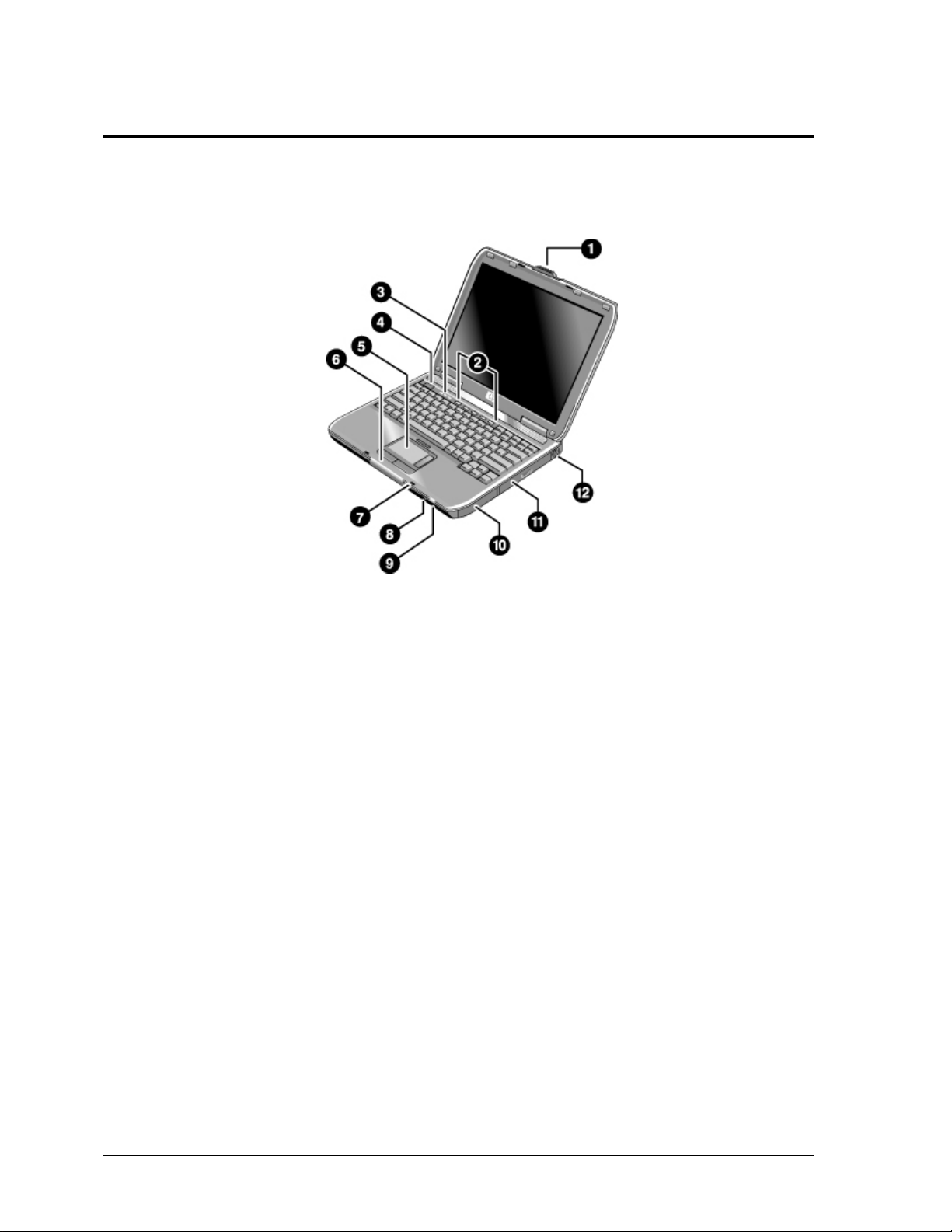
Features
The following illustrations show the notebook’s main external features. For an exploded view of the
notebook, see page 4-2.
Figure 1-1. Front View
HP Pavilion ze4x00, HP nx9005 and nx9000,
Compaq Evo Notebook N1050v and N1010v,
and Compaq Presario 2100 and 1100
1. Notebook open/close latch
2. One-touch buttons
3. Keyboard status lights
4. Power button: turns the notebook on and off
5. Touch pad, scroll pad, Select buttons, and plus
on-off button
6. Main status lights (left to right): power mode,
hard disk activity, and battery
7. Microphone option (not available)
8. Infrared port (select models only)
9. Wireless on-off button and indicator light
(select models only)
10. Battery
11. CD-ROM, DVD, or other drive
12. PS/2 keyboard or PS/2 mouse port
(supports Y adapter)
1-8 Product Information Service Manual
Page 16
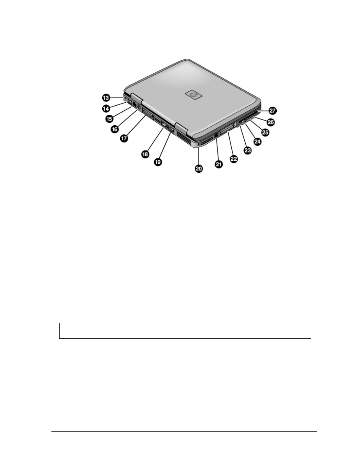
Figure 1-2. Back View
HP Pavilion ze4x00
HP nx9005 and nx9000
13. AC adapter jack
14. Two universal Serial Bus (USB) ports
15. LAN port (select models only)
16. S-Video port (select models only)
17. Parallel port (LPT1): use this port for a parallel
printer or other parallel device
18. Serial port (COM1): use this port for a serial
mouse, modem, printer, or other serial device
19. External monitor port
20. Kensington lock slot (security connector)
21. Modem port (select models only)
22. PCMCIA card and CardBus slot and button
23. IEEE 1394 port (select models only)
24. Audio jacks (left to right): external microphone
and audio out (headphones)
25. Volume controls (select models only)
26. Audio mute button and audio mute light
(select models only)
27. Floppy drive (select models only)
NOTE: Compaq Evo Notebook N1050v, N1010v, and Compaq Presario 2100 and 1100 very similar
except for logo.
Service Manual Product Information 1-9
Page 17
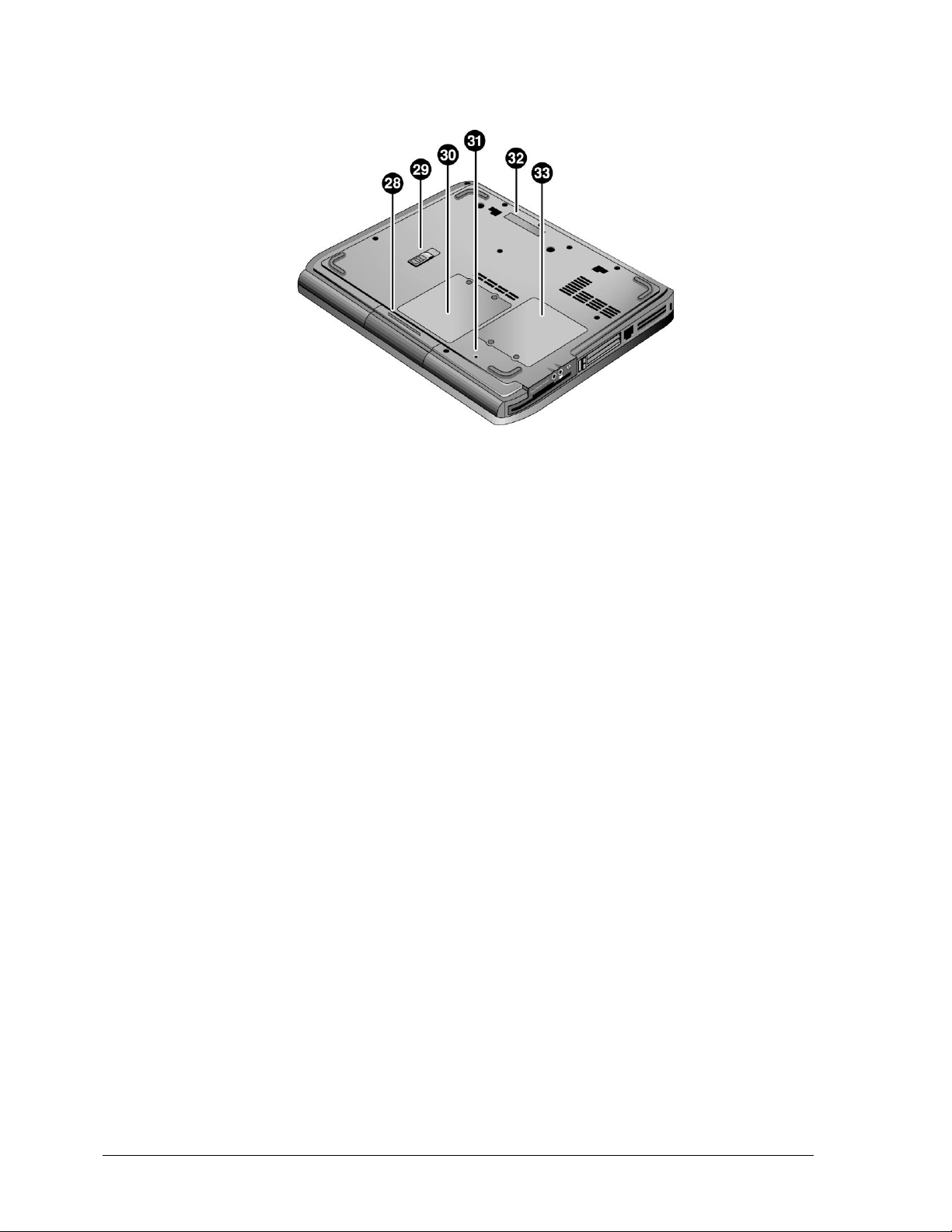
28. Hard disk drive
29. Battery latch
30. SDRAM door
Figure 1-3. Bottom View
HP Pavilion ze4x00, HP nx9005 and nx9000,
Compaq Evo Notebook N1050v and N1010v,
and Compaq Presario 2100 and 1100
31. Reset button
32. Port replicator connect (select models only)
33. Mini PCI door (no user parts inside)
1-10 Product Information Service Manual
Page 18
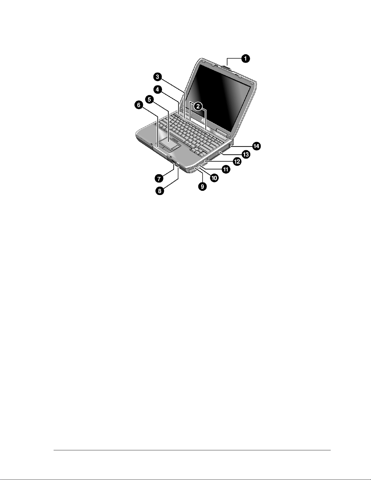
Figure 1-4. Front View
HP Pavilion ze5x00,
HP nx9010 and HP nx9008, and
Compaq Presario 2500
1. Notebook open/close latch
2. One-touch buttons
3. Keyboard status lights
4. Power button: turns the notebook on and off
5. Touch pad, scroll pad, Select buttons, and plus
on-off button
6. Main status lights (left to right): power mode,
hard disk activity, and battery
7. Infrared port (select models only)
8. Wireless on-off button and indicator light
(select models only)
9. Audio mute button and audio mute light
(select models only)
10. Battery
11. Volume controls (select models only)
12. Audio jacks (left to right): external microphone
and audio out (headphones)
13. CD-ROM, DVD, or other drive
14. Universal Serial Bus (USB) port
Service Manual Product Information 1-11
Page 19
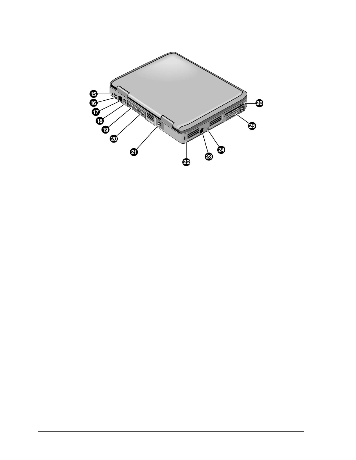
Figure 1-5. Back View
HP Pavilion ze5x00, HP nx9010, and HP nx9008
15. AC adapter jack
16. Two universal Serial Bus (USB) ports
17. LAN port (select models only)
18. External keyboard/mouse port
19. Parallel port (LPT1): use this port for a parallel
printer or other parallel device
20. External monitor port
21. S-Video port (select models only)
22. Kensington lock cable slot (security connector)
23. Modem port (select models only)
24. IEEE 1394 port (select models only)
25. PCMCIA card and CardBus slot and button
26. Floppy drive (select models only)
1-12 Product Information Service Manual
Page 20
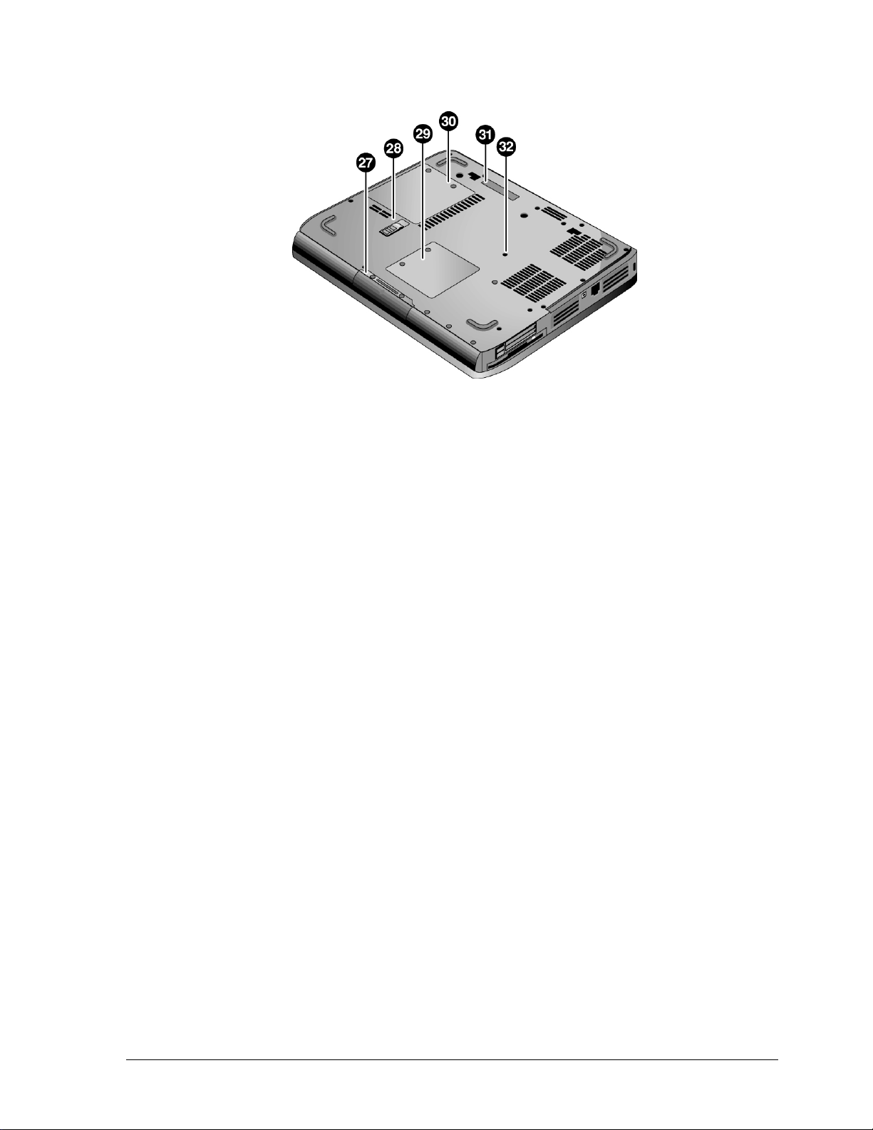
Figure 1-6. Bottom View
HP Pavilion ze5x00, HP nx9010, HP nx9008,
and Compaq Presario 2500
27. Hard disk drive
28. Battery latch
29. Mini PCI door (no user parts inside)
30. SDRAM door
31. Port replicator connect (select models only)
32. Reset button
Service Manual Product Information 1-13
Page 21
Operation
This section gives an overview of the notebook’s operation.
Turning the Notebook On and Off
You can start and stop your notebook using its power button. However, at certain times you might want to
use other methods to start or stop the notebook—depending on power considerations, types of active
connections, and start-up time.
NOTE: This manual describes the notebook in its original factory configuration, with all settings at their
default values.
Power mode To enter this mode
On
Power mode status light is on
Standby mode
Saves significant power
Turns off the display and other components
Maintains current session in RAM
Restarts quickly
Restores network connections
Power mode status light blinks
Hibernation mode
Saves maximum power
Saves current session to disk, and then shuts down.
Restores network connections
Power mode status light is off
Shut down (off)
Saves maximum power
Turns off without saving current session
At startup, resets everything, starts a new session, and
restores network connections.
Power mode status light is off
To turn on: Press the power button to restart, or to resume your session from Standby or Hibernation mode.
Table 1-2. Activating Power Modes
Press the power button
Press the power button
–or–
select Start > Turn Off Computer > Stand By (Windows XP)
–or–
select Start > Shut Down > Standby (Windows 2000)
–or–
allow timeout
Press
Fn+F12
–or–
select Start > Shut Down > Hibernate (Windows 2000)
–or–
allow timeout
Select Start > Turn Off Computer > Turn Off (Windows XP)
–or–
Select Start > Shut Down > Shut down (Windows 2000)
–or–
press the power button for 4 seconds (only if the Start menu
procedure doesn’t work)
1-14 Product Information Service Manual
Page 22
Checking the Status of the Notebook
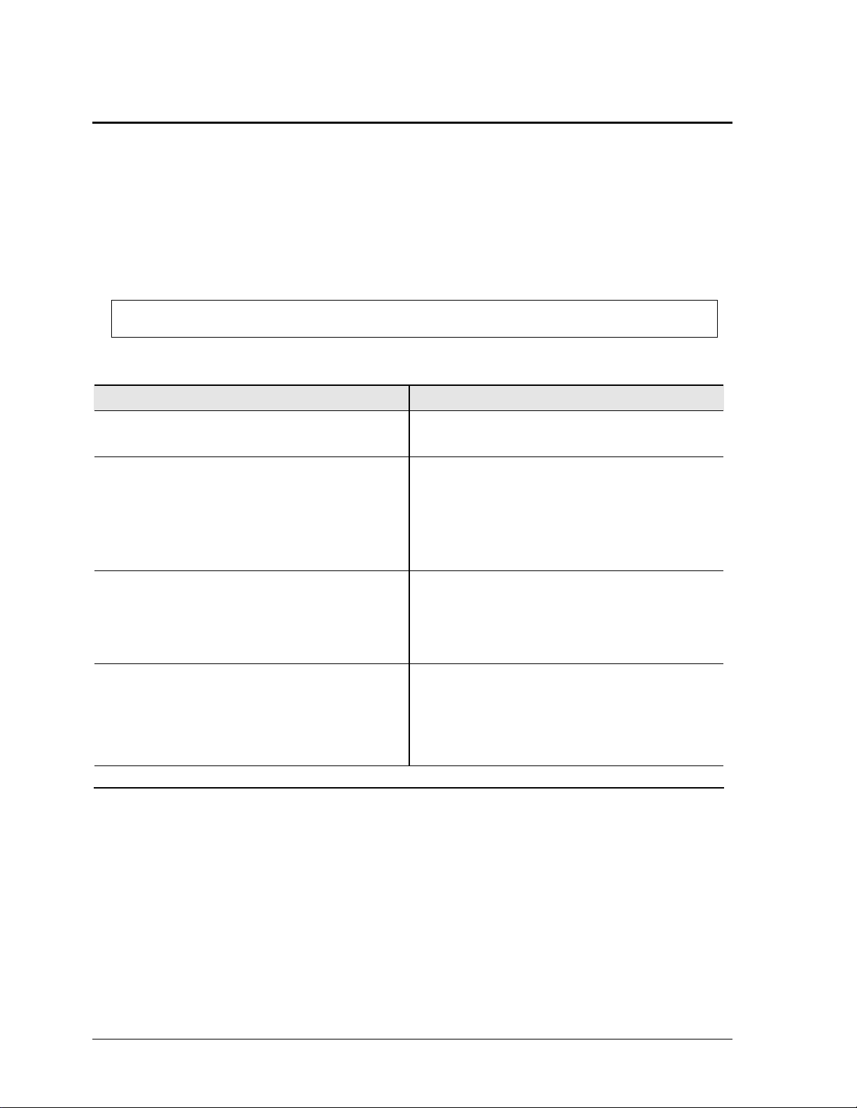
The main status lights on the front of the notebook report power status, battery status, and hard disk activity.
Hard disk drive activity
Table 1-3. Main Status Lights (front of notebook)
Meaning
Power status
On: notebook is on (even if the display is off).
Blinking: notebook is in Standby mode.
Off: notebook is off or in Hibernation mode.
On: notebook is accessing the hard disk drive.
Battery status
Green: The AC adapter is connected and the battery is fully charged.
Amber: The AC adapter is connected and the battery is charging.
Blinking: The AC adapter is connected and the battery is missing or has a fault.
Off: The AC adapter is not connected.
The keyboard status lights, located above the keyboard, indicate the states of the keyboard locks.
Table 1-4. Keyboard Status Lights
Meaning
Caps Lock
Caps Lock is active.
Num Lock
Num Lock is active. (The Keypad Lock must also be on to use the embedded keypad.)
Keypad Lock
The embedded keypad is active (Fn+F8). Num Lock must also be on for the numeric keys;
otherwise, cursor control is active (as marked on an external keyboard).
Service Manual Product Information 1-15
Page 23

Using Fn Hot Keys
The combination of the Fn key plus another key creates a hot key—a shortcut key sequence—for various
system controls. To use a hot key, press and hold
keys.
Fn, press the appropriate second key, then release both
Hot Key Effect
Fn+F1
Fn+F2
Fn+F5
Fn+F8
Fn+F12
Fn+NumLock
Fn+Page Up
Fn+Page Down
Fn+Backspace
Decreases the display brightness
Increases the display brightness
Toggles among the built-in display, an external display, and simultaneous display on both.
Toggles the built-in keypad on and off. Does not affect an external keyboard. If Num Lock is on, then
the numeric functions are active; otherwise, cursor control is active (as marked on an external
keyboard).
Enters Hibernation mode
Toggles Scroll Lock on and off
Increases the audio volume and cancels the mute setting
Decreases the audio volume
Audio mute
Table 1-5. Fn Hot Keys
1-16 Product Information Service Manual
Page 24
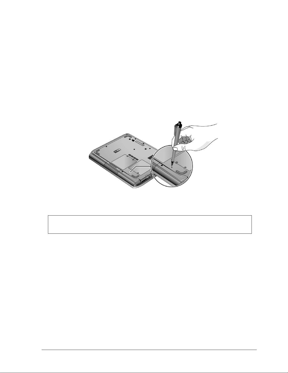
Resetting the Notebook
Occasionally, Windows or the notebook might stop responding, so that you cannot turn the notebook off. If
this happens, try the following in the order listed. Press the power button to restart.
• If possible, shut down Windows:
ctrl+alt+del, and then select Shut Down, Restart.
Press
If the system will not allow a software shutdown, press and hold down until the display shuts down
(about 4 seconds) and then release the power button. Press the power button again to restart.
• Use a ballpoint pen or a straightened paper clip to press the reset button on the bottom of the notebook.
Figure 1-7. Resetting the Notebook
NOTE: To boot from a CD, insert a bootable CD (such as the Recovery CDs) into the CD/DVD
drive, and then restart. Press esc when the HP logo appears, and then select the CD/DVD drive as
the temporary boot device.
Service Manual Product Information 1-17
Page 25

Specifications
The following tables list the specifications for the notebook and its accessories and are subject to change.
For the latest versions, see the HP Notebook Web site
http://www.hp.com/notebooks.
Physical Attributes
Processor and Bus
Architecture
Table 1-6. Specifications
Size (14-inch display): 328 × 272 × 33 mm (12.9 × 10.7 × 1.3 in)
Size (15-inch display): 328 × 272 × 35 mm (12.9 × 10.7 × 1.4 in)
Weight: 2.9 kg (6.5 lb) minimum, depending on configuration
HP Pavilion ze5600:
2.4-, 2.66-, 2.8-, or 3.06-GHz Mobile Intel Pentium 4 ProcessorM with
Intel Speed Step technology, 512-KB L2 cache, and 1.2- to 1.3-V core low-power
processor with 400-MHz processor system bus
-or-
2.6- or 2.8-GHz Intel Celeron processor with 128-KB L2 cache and 1.45-V core low-power
processor with 400-MHz processor system bus
HP Pavilion ze5500:
2.4-, 2.66-, 2.8-, or 3.06-GHz Mobile Intel Pentium 4 processor with
Intel Speed Step technology, 512-KB L2 cache, and 1.2- to 1.3-V core low-power
processor with 400-MHz processor system bus
-or-
2.6-GHz Mobile Intel Celeron processor with 128-KB L2 cache and 1.45-V core low-power
processor with 400-MHz processor system bus
HP Pavilion ze5400 or ze5300:
2.4-, 2.53-, 2.66-, or 2.8-GHz Intel Pentium 4 processor-D or 2.4-, 2.53-, 2.66-,
or 2.8-GHz Mobile Intel Pentium 4 with Intel Speed Step technology, 512-KB L2 cache,
processor with 400-MHz processor system bus
HP Pavilion ze5200:
2.4-, 2.53-, 2.66-, or 2.8-GHz Intel Desktop Pentium 4 processor-D with
Intel Speed Step technology, 512-KB L2 cache, and 1.2- to 1.3-V core low-power
processor with 400-MHz processor system bus
HP Pavilion ze4600 or ze4500:
1.87-GHz AMD Athlon XP-M with Intel Speed Step technology, 512-KB L2 cache, and 1.2to 1.3-V core low-power processor with 200- or 266-MHz (double-clocked) processor
system bus
HP Pavilion ze4400:
1.8- or 1.87-GHz AMD Athlon XP-M with Intel Speed Step technology,
512-KB L2 cache, and 1.2- to 1.3-V core low-power processor with 200- or 266-MHz
(double-clocked) processor system bus
1-18 Product Information Service Manual
Page 26

Processor and Bus
Architecture
(continued)
HP Pavilion ze4300:
1.8-, 2.0-, 2.2-, or 2.4-GHz Mobile Intel Pentium 4 processor-M with Intel Speed Step
technology, 512-KB L2 cache, and 1.2- to 1.3-V core low-power processor with
400-MHz processor system bus
-or-
1.8-, 2.0-, or 2.2-GHz Mobile Intel Celeron processor with 256-KB L2 cache and
1.45-V core low-power processor with 133-MHz processor system bus
-or-
1.46-, 1.53-, 1.67-, 1.80-, or 2.0-GHz Athlon processor with 256-KB L2 cache and
1.45-V core low-power processor with 133-MHz processor system bus
HP Pavilion ze4200:
1.8-, 1.9-, 2.0-, or 2.2-GHz Mobile Intel Pentium 4 processor-M with Intel Speed Step
technology, 512-KB L2 cache, and 1.2- to 1.3-V core low-power processor with
400-MHz processor system bus
-or-
1.6-, 1.7-, 1.8-, or 2.0-GHz Mobile Intel Celeron processor with 256-KB L2 cache and
1.45-V core low-power processor with 133-MHz processor system bus
-or-
1.46-, 1.53-, 1.67-, or 1.80-GHz AMD Athlon processor with 256-KB L2 cache and
1.45-V core low-power processor with 133-MHz processor system bus
HP Pavilion ze4100:
1.7-, 1.8-, or 2.0-GHz Mobile Intel Pentium 4 processor-M with Intel Speed Step
technology, 512-KB L2 cache, and 1.2- to 1.3-V core low-power processor with
400-MHz processor system bus
-or-
1.6-, 1.7-, or 1.8-GHz Mobile Intel Celeron processor with 256-KB L2 cache and
1.45-V core low-power processor with 133-MHz processor system bus
HP nx9010:
2.4-, 2.53-, or 2.66-GHz Intel Desktop Pentium 4 processor-D with
Intel Speed Step technology, 512-KB L2 cache, and 1.2- to 1.3-V core low-power
processor with 400-MHz processor system bus
-or-
2.0-GHz Mobile Intel Celeron-D processor with 256-KB L2 cache and
1.45-V core low-power processor with 133-MHz processor system bus
HP nx9008:
2.6- and 2.8-GHz Mobile Intel Celeron-D processor with 256-KB L2 cache and
1.45-V core low-power processor with 133-MHz processor system bus
HP nx9000:
1.8- or 2.0-GHz AMD Athlon processor with 256-KB L2 cache and 1.45-V core low-power
processor with 133-MHz processor system bus
Compaq Evo Notebook N1050v:
1.8-GHz Mobile Intel Pentium 4 Processor-M with Intel Speed Step technology,
512-KBL2 cache, and 1.2- to 1.3-V core low-power processor with 400-MHz processor
system bus
-or-
1.6-GHz Intel Celeron processor with 256-KB L2 cache and 1.45-V core low-power
processor with 133-MHz processor system bus
Compaq Evo Notebook N1010v:
1.6-GHz Intel Celeron processor with 256-KB L2 cache and 1.45-V core low-power
processor with 133-MHz processor system bus
Service Manual Product Information 1-19
Page 27

Processor and Bus
Architecture
(continued)
Video
Power
Mass Storage
RAM
Compaq Presario 2500:
1.8-, 2.0-, 2.4-, 2.53-, 2.66-, or 2.80-GHz Intel Desktop Pentium 4 processor-D with
Intel Speed Step technology, 512-KB L2 cache, and 1.2- to 1.3-V core low-power
processor with 400-MHz processor system bus
Compaq Presario 2100:
1.8-, 1.9-, 2.0-, or 2.2-GHz Mobile Intel Pentium 4 Processor-M with Intel Speed Step
technology, 512-KB L2 cache, and 1.2- to 1.3-V core low-power processor with
400-MHz processor system bus
-or-
2.53-GHz Intel Desktop Pentium 4 processor-D with Intel Speed Step technology,
512-KB L2 cache, and 1.2- to 1.3-V core low-power processor with 400-MHz processor
system bus
-or-
1.6-, 1.7-, 1.8-, or 2.0-GHz Intel Celeron processor with 256-KB L2 cache and
1.45-V core low-power processor with 133-MHz processor system bus
-or-
1.46-, 1.53-, 1.67-, or 1.80-GHz AMD Athlon processor with 256-KB L2 cache and
1.45-V core low-power processor with 133-MHz processor system bus
Compaq Presario 1100:
1.6- or 1.8-GHz Intel Celeron processor with 256-KB L2 cache and 1.45-V core low-power
processor with 133-MHz processor system bus
14.1-inch XGA (1024 × 768), or 15.0-inch XGA (1024 × 768) or SXGA+ (1400 × 1050)
active-matrix (TFT) LCD display
Hardware 3D acceleration, hardware DVD acceleration
External monitors up to 1600 × 1200 resolution, 16M colors, and at least 85 Hz refresh rate
(only 60 Hz at 1400 × 1050). Refresh rate and clarity may vary depending on monitor,
resolution, and color depth
ATI Mobility Radeon graphics accelerator with 16-, 32-, or 64-MB DDR graphics memory,
4x AGP graphics capability
Dual display capability (depends on operating system support)
Rechargeable lithium-ion (14.8 Vdc) or nickel-metal-hydride (9.6 Vdc) battery with LED
charge-level gauge
Battery life: up to 3 (Li ion) or 2 (NiMH) hours typical (varies with model, usage, and power
settings)
Fast battery recharge: 2 hours when system is off, 3 hours when system is on.
Low-battery warning
Suspend/resume capability
Universal AC adapter: 100–240 Vac (50/60 Hz) input, 19 Vdc output, or 75 W
20- to 60-GB removable hard drive with Ultra-DMA 100 interface
1.44-MB floppy drive (certain models)
24x CD-ROM, 8x DVD, CD-RW, or CD-RW/DVD drive (or higher)
At least 128 MB SDRAM preinstalled
HP Pavilion ze5x00, ze4x00, Compaq Evo N1050v, Compaq Presario 2500, and Compaq
Presario 2100:
2 slots for PC2100 DDR-266 SDRAM modules
Up to 1 GB (1024 MB) SDRAM using 512 MB modules
Compaq Evo N1010v and Presario 1100:
2 slots for PC2100 DDR-266 SDRAM modules
Up to 512 MB SDRAM using 256 MB modules
1-20 Product Information Service Manual
Page 28
Audio System
Keyboard and
Pointing Device
LAN
(select models only)
Wireless LAN
(select models only)
Stereo sound via 2 built-in speakers
3D-enhanced audio
Volume and mute buttons (certain models)
Headphone-out and microphone-in
87/88-key touch-type QWERTY keyboard with 101/102 key emulation. Embedded
numeric keypad.
12 function
5 user-programmable One-Touch buttons
Touch pad with integrated scroll pad, on-off button and indicator
Left and right Select buttons
Ethernet 10Base-T (10 Mbps) and 100Base-TX (100 Mbps) support
Supports wake-on-LAN, fast IP, DMI, dRMON
MBA (Managed Boot Agent) support for PXE/BINL, NCP/IPX, DHCP
802.11b or 802.11g (54g)
(Fn) keys
Service Manual Product Information 1-21
Page 29
Accessory Description
Memory
F4694-60901
317434-001
F4695-60901
317435-001
F4696-60901
317436-001
Hard Drives
0950-4193
319412-001
0950-4318 HDD-20 GB 9.5mm,
0950-4287 HDD-20 GB 9.5mm,
0950-4168 HDD-30 GB 9.5mm,
0950-4162
319413-001
0950-4319 HDD-30 GB 9.5mm,
0950-4360 HDD-30 GB 9.5mm,
0950-4176 HDD-30 GB 9.5mm,
0950-4320
319414-001
0950-4288 HDD-40 GB 9.5mm,
319415-001 SPS-DRV HD 60 GB
319416-001 SPS-DRV HD 60 GB
320692-001 SPS-DRV HD 80 GB
Power Options
F4600-60901 AC-Adapter-Ultraslim
F4809-60901 Battery, Li ion 4.4AHr
128MB DDR266B
256MB DDR266B
512MB DDR266B
HDD-20 GB 9.5mm,
Hitachi ATA100
IBM ATA100 FDB
TOSH ATA100 FDB
Hitachi ATA100
HDD-30 GB 9.5mm,
IBM (diablo) ATA100
IBM ATA100 FDB
(Cascade)
TITAN Toshiba
ATA100 (TITAN)
Toshiba ATA100
HDD-40 GB 9.5mm,
IBM ATA100 FDB
Toshiba ATA100
(4200 rpm)
(5400 rpm)
(4200 rpm)
Delta 75W s/PFC
Table 1-7. Accessories
HP Pavilion
ze5x00
HP nx9010
and
nx9008
Compaq
Presario
2500
HP Pavilion
ze4x00
HP nx9005
Compaq
Evo N10
50v
• • • •
• • • •
• • •
HP Pavilion
ze4600
ze4500
ze4400
ze4200
HP nx9000
Compaq
Presario
2100
Compaq
Evo
N1010v
Compaq
Presario
1100
HP Pavilion
ze4100
• • • • •
• •
• •
• •
•
• • • •
• •
• •
• •
• • • •
•
• • •
• •
• •
• •
• • • • •
1-22 Product Information Service Manual
Page 30
Accessory Description
319411-001 8 Cell Li ion
8120-6312
317444-011
8120-6314 Cord, Pwr, Europe
317444-002 SPS-CORD-AC PWR
317444-061 SPS-CORD-AC PWR
8120-6316
317444-291
317444-AD1 SPS-CORD-AC PWR 2
8120-8373
317444-AA1
317444-101 SPS-CORD-AC PWR
317444-111 SPS-CORD-AC PWR
317444-AB1 SPS-CORD-AC PWR
8120-8699
317444-031
8120-6313
317444-001
PC Cards
F4640-60978
319468-051
F4640-60977
319468-002
Docking
F4808-60901 Port Replicator Assy
F4808-60902 Simple Port Replicator
Cord, Pwr, Austr
ABG (2w)
ABB (2w)
2 WIRE-INTL
2 WIRE-IT
Cord, Pwr, Japan
ABJ (2w)
WIRE-KOR
Cord, Pwr, People’s
Republic of China
AB2 (2w)
2 WIRE-SWE
2 WIRE-SWI
2 WIRE-TAI
Cord, Pwr, UK (EPSR) for
Hong Kong (2w)
Cord, Pwr, US ABA (2w)
Card, Mini PCI-802.11B
France
Card, Mini PCI-802.11B
worldwide
hp/Compaq
HP Pavilion
ze5x00
HP nx9010
and
nx9008
Compaq
Presario
2500
HP Pavilion
ze4x00
HP nx9005
Compaq
Evo N10
50v
HP Pavilion
ze4600
ze4500
ze4400
ze4200
HP nx9000
Compaq
Presario
2100
Compaq
Evo
N1010v
Compaq
Presario
1100
HP Pavilion
ze4100
• • •
• •
•
•
• •
•
•
•
•
•
• • •
• • •
• • • •
• • • • •
• • •
• •
Service Manual Product Information 1-23
Page 31

Internal Design
The motherboard PCA is the central component of the notebook’s design. It plays a role in virtually
all system functions. The CPU module and most other subsystems connect to the motherboard.
The following figure shows the connections among the notebook’s replaceable electronic modules.
Table 1-8 on page 1-25 lists the roles that these modules play in the notebook’s functional subsystems.
Figure 1-8. Replaceable Module Diagram
1-24 Product Information Service Manual
Page 32

Bootup
Processor
Memory
Power
Display
Hard disk
Floppy drive
Keyboard
PS/2
TouchPad
Audio
Status
Serial
Parallel
Infrared
PS/2 port
USB
S-Video
Table 1-8. Functional Structure Description
CPU module
Motherboard
Hard disk drive
Floppy drive
CPU module
Motherboard
Motherboard
SDRAM module
Battery
Motherboard
Switchboard PCA
AC adapter
Motherboard
SDRAM module
Display assembly
Motherboard
Hard disk drive
Motherboard
Floppy drive
Motherboard
Switchboard PCA
Keyboard
Motherboard
Top case
Motherboard
Speaker assembly
Motherboard
Switchboard PCA
Top case
Motherboard I/O controller, serial connector
Motherboard I/O controller, parallel connector
Motherboard
IR PCA
Motherboard PS/2 connector, keyboard controller
Motherboard Bus controller (South Bridge), USB connector
Motherboard I/O controller, S-video connector (certain models)
Main processor (MMO)
Primary system circuitry, system BIOS
First source of disk-based startup code
Second source of disk-based startup cod.
Main processor, numeric data processor, L1 and L2 cache
Primary system circuitry
Video RAM (XE4500)
Changeable SDRAM (2 slots), video RAM (XE4100)
Power storage
AC adapter socket, reset button, lid switch, power supply, power control circuitry
Power button
AC-to-DC converter
Graphics controller, video RAM
Display output, backlight, power converter for backlight
Hard disk controller
Hard disk mechanism
I/O controller, floppy connector
Floppy drive mechanism
Keyboard BIOS, keyboard controller
Power switch, one-touch buttons
Key switches
Keyboard circuitry, keyboard controller, keyboard BIOS
Touch pad sensor, Select buttons, controller (PS/2 output)
Audio controller, audio decoder, speaker amplifier, microphone, external audio
jacks, headphone amplifier, audio-off switch
Speakers
LED circuitry, keyboard controller
Keyboard LEDs
Main status LEDs
I/O controller
Infrared transmitter/receiver
Service Manual Product Information 1-25
Page 33

Port Replicator
PCMCIA
Wireless LAN
(select
models only)
LAN
Modem
Motherboard Port replicator logic, port replicator connector (certain models)
Motherboard
PCMCIA socket
Mini PCI
Antenna PCAs
IR PCA
Motherboard LAN circuitry, bus controller, LAN connector
Motherboard Modem circuitry (select models), modem connector
PCMCIA controller
PCMCIA connector
I/O controller, radio, radio frequency circuitry
Transmit/receive antennas
On/off switch, indicator light
1-26 Product Information Service Manual
Page 34

Removal and Replacement
This chapter tells you how to remove and replace the notebook’s components and assemblies. The items
marked by • in the following table are user-replaceable.
Table 2-1. Removal Cross-Reference
2
Assembly, display (page 2-23)
• Assembly, speaker (page 2-15)
• Battery, main (page 2-4)
• Card, wireless LAN Mini PCI (page 2-7)
Case, bottom (page 2-59)
Case, top (page 2-26)
CPU module (page 2-44)
• Cover, keyboard (page 2-16)
• Door, Mini PCI (page 2-7)
• Door, SDRAM (page 2-5)
Doors, PCMCIA (page 2-60)
Drive, CD/DVD (page 2-20)
Drive, floppy (page 2-32)
• Drive, hard disk (page 2-9)
• Feet, rubber (page 2-12)
Heat sink (with fan) (page 2-40)
• Keyboard (page 2-16)
• Module, CPU (page 2-44)
Module, RJ11/1394 (page 2-48)
Module, SDRAM (page 2-5)
PCA, antennas (page 2-60)
PCA, audio (page 2-38)
PCA, I/R (page 2-36)
PCA, motherboard (page 2-50)
PCA, switchboard (page 2-19)
• Rubber screw plugs, display (page 2-12)
CAUTION: Always provide proper grounding when performing repairs. Without
proper grounding, an electrostatic discharge can damage the notebook and its
components.
NOTE: Reassembly steps are the reverse of the removal steps. Reassembly notes are included at the
end of each section below.
Symbols like these are displayed throughout this chapter to show approximate full-size
screw outlines. You can use these to verify the sizes of screws before you install them. Installing
a wrong-size screw can damage the notebook. (The symbol at the left represents an M2.5×4.0mm
T-head screw.)
Service Manual Removal and Replacement 2-1
Page 35

Table 2-2. Required Equipment
• 0 and 1 Phillips screwdrivers, preferably magnetized
• Small flat-blade screwdriver
• 5mm nut driver
Table 2-3. Recommended Screw Torque Values
Screw Thread Size Torque (cm-kgf) Torque (in-lbf)
M2 2,0–2,5 1.7–2.2
M2.5 (hinges) 3,5–4,0 3.0–3.4
M2.5 (other) 2,5–3,0 2.2–2.6
M3 2,5–3,0 2.2–2.6
Standoff, hex 2,5–3,0 2.2–2.6
2-2 Removal and Replacement Service Manual
Page 36

Disassembly Flowchart
The following diagram shows the general “path” you will use when disassembling the notebook to
access any particular component.
Figure 2-1. Disassembly Flow
Service Manual Removal and Replacement 2-3
Page 37

Removing the Battery
(User-Replaceable)
Required Equipment
None
Removal Procedure
Slide the battery’s release latch, and then pull the battery out of its compartment.
Figure 2-2. Removing the Battery
2-4 Removal and Replacement Service Manual
Page 38

Removing an SDRAM Module
(User-Replaceable)
The notebook has no system memory built into its motherboard, but has 2 slots for SDRAM modules. One
slot contains an SDRAM module that was factory installed.
NOTE: HP Pavilion ze5300, ze5200, ze4300, ze4200, and ze4100, HP nx9010, nx9005 and nx9000,
Compaq Evo Notebook N1050v and N1010v, and Compaq Presario 2500, 2100, and 1100 notebooks use
only DDR266 SDRAM modules. Using the wrong type of module prevents the notebook from booting.
CAUTION: Handle the SDRAM module only by its edges and provide proper grounding, or
you might damage the module through electrostatic discharge.
Required Equipment
1 Phillips screwdriver
Removal Procedure
1. Unplug the AC adapter, if present, and then remove the battery.
2. On the bottom of the notebook, loosen the captive screws holding the SDRAM door, and then remove
the door.
3. Press outward on the latches at the sides of the SDRAM module to release it (the SDRAM module
pops up).
4. Carefully pull the SDRAM module out of the connector.
Figure 2-3. Removing an SDRAM Module
HP Pavilion 4x00, HP nx9005 and nx9000,
Compaq Evo Notebook N1050v and N1010v, and
Compaq Presario 2100 and 1100 Models
Service Manual Removal and Replacement 2-5
Page 39

NOTE: The SDRAM door on HP Pavilion ze5x00, HP nx9010 and nx9008, and Compaq Presario 2500
models is located in the rear left corner of the notebook bottom, as indicated in Figure 2-4. The procedure
for removing the SDRAM door and modules is the same for all notebook models.
Figure 2-4. Removing an SDRAM Module
HP Pavilion ze5x00, HP nx9010, nx9008, and
Compaq Presario 2500 Models
Reassembly Notes
Carefully press the SDRAM module into the connector at an angle of about 30°, until it is fully
inserted, and then press down on both sides of the SDRAM module until the latches snap closed.
2-6 Removal and Replacement Service Manual
Page 40

Removing the Wireless LAN Mini PCI Card
(User-Replaceable)
Certain notebooks include a wireless LAN Mini PCI card under the Mini PCI door on the bottom of
the notebook.
CAUTION: Handle the Mini PCI card only by its edges and provide proper grounding, or you
might damage the card through electrostatic discharge.
Required Equipment
0 Phillips screwdriver
Removal Procedure
1. Unplug the AC adapter, if present, and then remove the battery.
2. On the bottom of the notebook, loosen the captive screws holding the Mini PCI door, and then remove
the door.
CAUTION: Be careful when connecting and disconnecting the antenna cables from the Mini PCI
card. Damaged cables or connectors can degrade notebook performance.
3. Disconnect the 2 antenna cables from the Mini PCI card.
4. Press outward on the latches at the sides of the Mini PCI card to release it (the Mini PCI card pops up).
5. Carefully pull the Mini PCI card out of the connector.
Figure 2-5. Removing the Mini PCI Card
HP Pavilion ze4x00, HP nx9005 and nx9000,
Compaq Evo Notebook N1050v and N1010v, and
Compaq Presario 2100 and 1100 Models
Service Manual Removal and Replacement 2-7
Page 41

NOTE: The Mini PCI Card door on HP Pavilion ze5x00, HP nx9010 and HP nx9008, and
Compaq Presario 2500 models is located in the front center area of the notebook bottom, as indicated in
Figure 2-6. The procedure for removing the Mini PCI door and card is the same for all notebook models.
Figure 2-6. Removing the Mini PCI Card
HP Pavilion ze5x00, HP nx9010 and nx9008, and
Compaq Presario 2500 Models
Reassembly Notes
Carefully press the Mini PCI card into the connector at an angle of about 30°, until it is fully
inserted, and then press down on both sides of the Mini PCI card until the latches snap closed.
2-8 Removal and Replacement Service Manual
Page 42

Removing the Hard Disk Drive
(User-Replaceable)
Required Equipment
1 Phillips screwdriver
Removal Procedure
NOTE: If you are installing a new hard disk drive, load the factory software and operating system on the
drive as described in “Recovering the Factory Software”, as shown on the next page.
1. Unplug the AC adapter, if present, and then remove the battery.
2. On the bottom of the notebook, remove the hard disk drive rubber screw plugs and
M2.5×6.0mm screws. (The number of plugs and screws varies by model.)
3. Carefully pull the hard disk drive out of the notebook.
Figure 2-7. Removing the Hard Disk Drive
Service Manual Removal and Replacement 2-9
Page 43

4. Remove the four M3.0×4.0mm screws from the hard disk drive and hard disk drive tray, and
then lift the drive out of the tray.
5. Remove the connector bar from the hard disk drive.
See note below
NOTE: Connector bar not used on HP Pavilion ze5x00 series
Figure 2-8. Removing the Hard Disk Drive Tray
2-10 Removal and Replacement Service Manual
Page 44

Recovering the Factory Software
The following procedure describes how to recover the notebook’s original operating system and
drivers. This process can take up to 15 minutes to complete. (For more information about recovering
the factory software installation, see the readme.txt file in the root directory of the Recovery CDs.)
CAUTION: Do not interrupt the following process or unplug the AC adapter until the process
completes.
1. Connect the AC adapter to the notebook.
2. Insert the Restore CD (or the Operating System) disk 1 into the notebook’s CD/DVD drive. If the
notebook is turned off, use a pin or straightened paper clip to press the release switch on the drive door
to open it.
3. Turn on or restart the notebook.
4. When the HP logo appears, press esc to display the Boot menu.
5. Use the arrow keys to select the CD/DVD drive as the first boot device, and then press enter.
6. When the dialog box appears, follow the displayed instructions. If prompted, accept the recommended
partition size.
To create the Utility partition without installing the factory software, select Advanced, and then select
not to install the operating system.
If the hard disk is partitioned into several logical drives, you can install the factory software on drive C
without affecting other drives. select Advanced and then select to restore only the C partition.
7. When prompted to reboot the notebook, press ctrl+alt+del, and then follow any instructions that appear.
8. When the operating system has been installed and while Windows is running, replace the OS CD with
the Driver Recovery CD. If autorun is not enabled, select Start > Run. Then type
D:\SWSETUP\APPINSTL\SETUP.EXE (assuming “D:” is your drive designation), and then hit enter.
9. Follow the on-screen instructions for installing the drivers.
10. After the drivers have been installed, the application software may be installed.
Service Manual Removal and Replacement 2-11
Page 45

Replacing Small Parts
The user can replace the following small parts.
Part Replacement Procedure
Rubber screw plugs, display
(on display bezel)
Door, Mini PCI
Door, memory
Feet, rubber
(on bottom of notebook)
Rubber cover, docking port
(ze4500 only)
Cover, modem port
Table 2-4. Replacing Small Parts
Insert a small flat-blade screwdriver under the rubber screw plug and pry it loose. To replace,
firmly press the adhesive side of the screw plug into the recess.
On the bottom of the notebook, loosen the screws that secure the Mini PCI door to the
bottom case, and then remove the door.
On the bottom of the notebook, loosen the screws that secure the SDRAM module door to
the bottom case, and then remove the door.
Insert a small flat-blade screwdriver under the foot and pry it loose. To replace, firmly press
the adhesive side of the foot into the recess.
Grasp the rubber docking port cover with your fingers and gently remove it. To replace, firmly
press the docking port cover into the opening in the bottom case.
Insert a small flat-blade screwdriver at the top of the cover and gently pry it loose. To
replace, insert the cover into the modem port opening.
2-12 Removal and Replacement Service Manual
Page 46

Removing the Keyboard Cover
Required Equipment
• 1 Phillips screwdriver
• Small flat-blade screwdriver
Removal Procedure
1. Unplug the AC adapter, if present, and then remove the battery.
2. Remove the two M2.5×4.0mm hinge cover screws that secure the keyboard cover to the rear of the
notebook.
3. Carefully insert a flat-blade screwdriver blade under the keyboard cover near the right end, then near
the center, then near the left end, and then gently lift up the center of the cover. Gently pry up the hinge
covers if needed, being careful not to damage the plastics or wireless antenna underneath.
CAUTION: Be careful not to damage the antenna PCA that is connected to the left and right
display assembly hinges. Damaging either antenna PCA can degrade notebook performance.
Service Manual Removal and Replacement 2-13
Page 47

4. If necessary, while holding the center of the cover, carefully insert the flat-blade screwdriver under the
right side of the display assembly hinge, gently pry up, and then lift the cover out. This procedure might
need to be repeated on the left side of display assembly hinge to completely remove the cover.
Figure 2-9. Removing the Keyboard Cover
NOTE: When removing the keyboard cover on HP Pavilion ze5300 and ze5200, HP nx9010, and
Compaq Presario 2500 models, disconnect the speaker cable as indicated in Figure 2-10.
Figure 2-10. Disconnecting the Speaker Cable
Reassembly Note
Insert the tabs on the left- and right-center of the panel into the mating slots under the keyboard, and then
press the panel into place.
2-14 Removal and Replacement Service Manual
Page 48

Removing the Speaker Assembly
(User-Replaceable)
NOTE: The following speaker assembly removal procedures apply only to HP Pavilion ze4x00,
HP nx9005 and nx9000, Compaq Evo Notebook N1050v and N1010v, and Compaq Presario 2100 and
1100 Series notebooks. The HP Pavilion ze5x00, HP nx9010 and HP nx9008, and Compaq Presario 2500
Series notebook speakers are integrated into the top case. Refer to the “Removing the Top Case” section
later in this chapter for procedures on removing the top case and speakers on the HP Pavilion ze5x00,
HP nx9010 and HP nx9008, and Compaq Presario 2500 Series notebooks.
Required Equipment
1 Phillips screwdriver
Removal Procedure
1. Unplug the AC adapter, if present, and then remove the battery.
2. Remove the keyboard cover (page 2-13).
3. Remove the M2.5×6.0mm screw that secures the speaker assembly to the top case.
4. Disconnect the 4-wire cable from the switchboard PCA.
Figure 2-11. Removing the Speaker Assembly
Service Manual Removal and Replacement 2-15
Page 49

Removing the Keyboard
Required Equipment
1 Phillips screwdriver
Removal Procedure
1. Unplug the AC adapter, if present, and then remove the battery.
2. Remove the keyboard cover (page 2-13).
3. Remove the four M2.5×4.0mm screws that secure the keyboard to the top case.
4. Lift up on the keyboard at the switchboard PCA end, and then pull it toward the display assembly to
release the tabs from the top case.
5. Turn the keyboard over, and then disconnect the motherboard cable.
6. Remove the keyboard.
Reassembly Notes
CAUTION: Do not excessively bend or fold the keyboard cable. Excessive flexing can
damage the keyboard cable connectors.
• Lay the keyboard face down on the top case, forward of its normal position, and then reconnect
the keyboard cable.
• Slide the metal tabs on the bottom of the keyboard into their slots in the top case, and then lower the
keyboard into place.
2-16 Removal and Replacement Service Manual
Page 50

Figure 2-12. Removing the Keyboard
Service Manual Removal and Replacement 2-17
Page 51

NOTE: This section applies only to HP Pavilion ze4x00, HP nx9005 and nx9000,
Compaq Evo Notebook N1050v and N1010v, and Compaq Presario 2100 and 1100 models.
Required Equipment
1 Phillips screwdriver
Removal Procedure
1. Unplug the AC adapter, if present, and then remove the battery.
2. Remove the keyboard cover (page 2-13).
3. Disconnect both the 2-wire and 4-wire cables that connect the switchboard PCA to the top case
and speaker assembly, respectively.
4. Remove the M2.5×4.0mm screw that secures the keyboard, and then switchboard PCA to the
top case (page 2-16).
5. Gently lift up on the keyboard, carefully remove the switchboard PCA from the top case, and then
disconnect the underside motherboard cable.
Figure 2-13. Removing the Switchboard PCA
HP Pavilion ze4x00, HP nx9005 and nx9000,
Compaq Evo Notebook N1050v and N1010v, and
Compaq Presario 2100 and 1100 Models
2-18 Removal and Replacement Service Manual
Page 52

Removing the Switchboard PCA
NOTE: This section applies only to HP Pavilion ze5x00, HP nx9010 and HP nx9008, and
Compaq Presario 2500 models.
Required Equipment
1 Phillips screwdriver
Removal Procedure
1. Unplug the AC adapter, if present, and then remove the battery.
2. Remove the keyboard cover (page 2-13).
3. Disconnect the 2-wire cable that connects the switchboard PCA to the display lid switch.
4. Remove the two M2.5×4.0mm screws that secure the switchboard PCA to the top case.
5. Gently lift up on the rear right edge of the switchboard PCA to disconnect the PCA from the
motherboard.
6. Remove the switchboard PCA.
Figure 2-14. Removing the Switchboard PCA
HP Pavilion ze5x00,
HP nx9010 and HP nx9008, and
Compaq Presario 2500 Models
Service Manual Removal and Replacement 2-19
Page 53

Removing the CD/DVD Drive
NOTE: This section applies only to HP Pavilion ze4x00, HP nx9005 and nx9000,
Compaq Evo Notebook N1050v and N1010v, and Compaq Presario 2100 and 1100 models.
Required Equipment
1 Phillips screwdriver
Removal Procedure
1. Unplug the AC adapter, if present, and then remove the battery.
2. Remove these additional assemblies:
Keyboard cover (page 2-13)
•
• Keyboard (page 2-16)
2-20 Removal and Replacement Service Manual
Page 54

3. Remove the 2 screws that secure the CD/DVD drive to the top case and motherboard.
NOTE: The screws that secure the CD/DVD drive are 2 different sizes. The front screw is a
M2.5×6.0mm screw. The back screw is a M2.5×4.0mm screw. Make sure these screws are installed in the
correct locations when reinstalling the CD/DVD drive.
4. Place your index finger in the top case opening, and then push out on the CD/DVD drive to release it
from the motherboard.
5. Remove the CD/DVD drive.
Figure 2-15. Removing the CD/DVD Drive
HP Pavilion ze4x00, HP nx9005 and nx9000,
Compaq Evo Notebook N1050v and N1010v, and
Compaq Presario 2100 and 1100 Models
Service Manual Removal and Replacement 2-21
Page 55

NOTE: This section applies only to HP Pavilion ze5x00, HP nx9010 and HP nx9008, and
Compaq Presario 2500 models.
Required Equipment
1 Phillips screwdriver
Removal Procedure
1. Unplug the AC adapter, if present, and then remove the battery.
2. Remove these additional assemblies:
Keyboard cover (page 2-13)
•
• Keyboard (page 2-16)
3. Remove the two M2.5×6.0mm screws that secure the CD/DVD drive to the top case and motherboard.
4. Place your index finger in the top case opening and push out on the CD/DVD drive to release it from
the motherboard.
5. Remove the CD/DVD drive.
Figure 2-16. Removing the CD/DVD Drive
HP Pavilion ze5x00,
HP nx9010 and HP nx9008, and
Compaq Presario 2500 Models
2-22 Removal and Replacement Service Manual
Page 56

Removing the Display Assembly
(Authorized Service Providers Only)
Required Equipment
1 Phillips screwdriver
Removal Procedure
1. Unplug the AC adapter, if present, and then remove the battery.
2. Remove the keyboard cover (page 2-13).
3. Remove the two M2.5×6.0mm retaining screws from the notebook rear panel.
4. Remove the M2.5×4.0mm screws from the left and right antenna PCAs. Relocate the antenna PCAs
away from the display assembly hinges.
5. Disconnect the display assembly cable from the motherboard.
6. Remove the six M2.5×6.0mm retaining screws that secure the display assembly to the top case.
(Note that there is a grounding strap at the left hinge.)
7. Lift the display assembly off of the notebook.
Service Manual Removal and Replacement 2-23
Page 57

Figure 2-17. Removing the Display Assembly
2-24 Removal and Replacement Service Manual
Page 58

Reassembly Notes
NOTE: After replacing the display assembly or motherboard, you must use the Service Utilities floppy
disk to reprogram the EEPROM on the motherboard for the new display.
1. Download the notebook series service package from the Partnership Web site (see page vii), and
then create a Service Utilities floppy disk as described in the package’s Readme file.
2. Plug in an AC adapter.
3. Insert the Service Utilities floppy disk in the floppy drive. If the unit has no internal floppy drive,
connect a USB floppy drive.
4. Turn on the notebook.
5. When you see the HP logo, press esc to display the boot menu, then boot from the floppy drive.
6. Select the option to update the display/LCD identification stored on the motherboard.
• Make sure you connect the grounding strap to the left display assembly hinge.
• When connecting the left and right antenna PCAs, make sure they are parallel with the display assembly
hinges.
Service Manual Removal and Replacement 2-25
Page 59

Removing the Top Case
(Authorized Service Providers Only)
NOTE: This section applies only to HP Pavilion ze4x00, HP nx9005 and nx9000,
Compaq Evo Notebook N1050v and N1010v, and Compaq Presario 2100 and 1100 models.
Required Equipment
1 Phillips screwdriver
Removal Procedure
1. Unplug the AC adapter, if present, and remove the battery.
2. Remove these additional assemblies:
Hard disk drive (page 2-9)
•
• Keyboard cover (page 2-13)
• Speaker assembly (page 2-23)
• Keyboard (page 2-16)
• Switchboard PCA (page 2-19)
• CD/DVD drive (page 2-20)
• Display assembly (page 2-23)
2-26 Removal and Replacement Service Manual
Page 60

3. Turn the notebook bottom side up with the front facing forward.
4. Remove the following M2.5×4.0mm screws:
One from the battery bay
•
• One from the hard disk drive bay
5. Remove the remaining 14 M2.5×6.0mm screws.
6. Turn the notebook top side up with the rear panel facing forward.
7. Remove the two M2.5×4.0mm screws from the rear panel.
8. Remove the two M2.5×6.0mm screws from the top case.
9. Lift the top case off of the notebook and then disconnect the touch pad cable from the motherboard.
Figure 2-18. Removing the Top Case
HP Pavilion ze4x00, HP nx9005 and nx9000,
Compaq Evo Notebook N1050v and N1010v, and
Compaq Presario 2100 and 1100 Models
Service Manual Removal and Replacement 2-27
Page 61

NOTE: This section applies only to HP Pavilion ze5x00, HP nx9010 and HP nx9008, and
Compaq Presario 2500 models.
Required Equipment
1 Phillips screwdriver
Removal Procedure
1. Unplug the AC adapter, if present, and then remove the battery.
2. Remove these additional assemblies:
Hard disk drive (page 2-9)
•
• Keyboard cover (page 2-13)
• Speaker assembly (page 2-15)
• Keyboard (page 2-16)
• Switchboard PCA (page 2-19)
• CD/DVD drive (page 2-20)
• Display assembly (page 2-23)
2-28 Removal and Replacement Service Manual
Page 62

3. Turn the notebook bottom side up with the front facing forward.
4. Remove the following 16 screws:
Six M2.5×7.0mm screws on the rear edge of the notebook
•
• Two M2.5×6.0mm screws on each side of the docking connector
• One M2.5×6.0mm screw behind the battery bay
• Three M2.5×7.0mm screws around the middle fan vent
• One M2.5×4.0mm screw in the battery bay
• Three M2.5×7.0mm screws on the front edge of the notebook
CAUTION: The 16 screws removed in step 4 are 3 different lengths. Be sure to note of the
correct location of each screw as it is removed and install it in the correct location. Failure to
follow this caution can result in damage to the notebook.
Figure 2-19. Removing the Top Case Screws
HP Pavilion ze5x00,
HP nx9010 and HP nx9008, and
Compaq Presario 2500 Models
Service Manual Removal and Replacement 2-29
Page 63

5. Turn the notebook top side up with the rear panel facing forward.
6. Remove the two M2.5×7.0mm screws from the rear of the bottom case.
Figure 2-20. Removing the Top Case Screws
HP Pavilion ze5x00,
HP nx9010 and HP nx9008, and
Compaq Presario 2500 Models
2-30 Removal and Replacement Service Manual
Page 64

7. Position the notebook so the front faces forward.
8. Disconnect the floppy drive flex cable from the low insertion force (LIF) connector to which it is
connected.
9. Release the ZIF connector to which the TouchPad cable is connected, and then disconnect the
TouchPad cable from the system board.
10. Remove the following 4 screws:
One M2.5×7.0mm screw next to the TouchPad cable
•
• Two M2.5×6.0mm screws in the center of the top case
• One M2.5×4.0mm screw on the right side of the top case
CAUTION: The 4 screws removed in step 10 are 3 different lengths. Be sure to note of the
correct location of each screw as it is removed and install it in the correct location. Failure to
follow this caution can result in damage to the notebook.
11. Lift the top case off of the notebook.
Figure 2-21. Removing the Top Case
HP Pavilion ze5x00,
HP nx9010 and HP nx9008, and
Compaq Presario 2500 Models
Service Manual Removal and Replacement 2-31
Page 65

Removing the Floppy Drive
(Authorized Service Providers Only)
NOTE: This section applies only to HP Pavilion ze4x00, HP nx9005 and nx9000,
Compaq Evo Notebook N1050v and N1010v, and Compaq Presario 2100 and 1100 models.
Required Equipment
1 Phillips screwdriver
Removal Procedure
1. Unplug the AC adapter, if present, and remove the battery.
2. Remove these additional assemblies:
Hard disk drive (page 2-9)
•
• Keyboard cover (page 2-13)
• Keyboard (page 2-16)
• Switchboard PCA (page 2-19)
• Display assembly (page 2-23)
• Top case (page 2-26)
2-32 Removal and Replacement Service Manual
Page 66

3. Remove the two M2.5×4.0mm screws (right side) that secure the hard disk drive guide to the
motherboard. (Note that the screws (left side) are missing. These screws were removed during the
top case removal procedure.)
4. Disconnect the motherboard cable.
5. Remove the two M2.5×4.0mm screws that secure the floppy drive to the motherboard.
6. Remove the floppy drive.
Figure 2-22. Removing the Floppy Drive
HP Pavilion ze4x00, HP nx9005 and nx9000,
Compaq Evo Notebook N1050v and N1010v, and
Compaq Presario 2100 and 1100 Models
Reassembly Notes
CAUTION: Do not excessively bend or fold the floppy drive cable. Excessive flexing can
damage the floppy drive cable connections.
• Connect the floppy drive cable to the motherboard prior to replacing the floppy drive and hard disk
drive guide.
• When replacing the hard disk drive guide, do not secure the left side to the motherboard. The left side
of the guide gets secured during the top case replacement procedure.
Service Manual Removal and Replacement 2-33
Page 67

NOTE: This section applies only to HP Pavilion ze5x00, HP nx9010 and HP nx9008, and
Compaq Presario 2500 models.
Required Equipment
• 1 Phillips screwdriver
Removal Procedure
1. Unplug the AC adapter, if present, and then remove the battery.
2. Remove these additional assemblies:
Hard disk drive (page 2-9)
•
• Keyboard cover (page 2-13)
• Keyboard (page 2-16)
• Switchboard PCA (page 2-19)
• Display assembly (page 2-23)
• Top case (page 2-26)
3. Remove the insulating tape that secures the floppy drive flex cable to the TouchPad bracket on
the top case.
4. Remove the four M2.5×6.0mm screws that secure the floppy drive and floppy drive bezel to
the top case.
5. Remove the floppy drive.
6. Remove the M2.0×3.0mm screw that secures the floppy drive bezel to the floppy drive.
7. Remove the floppy drive bezel.
2-34 Removal and Replacement Service Manual
Page 68

Figure 2-23. Removing the Floppy Drive
HP Pavilion ze5x00,
HP nx9010 and HP nx9008, and
Compaq Presario 2500 Models
Reassembly Notes
CAUTION: Do not excessively bend or fold the floppy drive cable. Excessive flexing can
damage the floppy drive cable connections.
Service Manual Removal and Replacement 2-35
Page 69

Removing the Infrared (I/R) PCA
(Authorized Service Providers Only)
Required Equipment
1 Phillips screwdriver
Removal Procedure
1. Unplug the AC adapter, if present, and then remove the battery.
2. Remove these additional assemblies:
Hard disk drive (page 2-9)
•
• Keyboard cover (page 2-13)
• Keyboard (page 2-16)
• Switchboard PCA (page 2-19)
• Display assembly (page 2-23)
• Top case (page 2-26)
2-36 Removal and Replacement Service Manual
Page 70

3. Disconnect the I/R PCA cable from the motherboard.
4. Remove the two M2.5×4.0mm screws that secure the I/R PCA to the bottom case.
5. Remove the I/R PCA.
Figure 2-24. Removing the I/R PCA
Reassembly Note
CAUTION: Use care when handling the I/R PCA cable. Damaging the cable can degrade
notebook performance.
Make sure you route the I/R PCA cable between the left screw hole and the bottom case.
Service Manual Removal and Replacement 2-37
Page 71

Removing the Audio PCA
(Authorized Service Providers Only)
NOTE: The following audio PCA removal instructions apply only to HP Pavilion ze5300 and ze5200,
HP nx9010, and Compaq Presario 2500 models.
Required Equipment
1 Phillips screwdriver
Removal Procedure
1. Unplug the AC adapter, if present, and then remove the battery.
2. Remove these additional assemblies:
Hard disk drive (page 2-9)
•
• Keyboard cover (page 2-13)
• Keyboard (page 2-16)
• Switchboard PCA (page 2-19)
• Display assembly (page 2-23)
• Top case (page 2-26)
3. Disconnect the audio PCA cable from the motherboard.
4. Remove the audio PCA cable from the clip on the bottom case.
2-38 Removal and Replacement Service Manual
Page 72

5. Remove the two M2.0×3.0mm flathead screws that secure the audio PCA shield to the
bottom case.
6. Remove the audio PCA shield.
7. Remove the M2.0×3.0mm flathead screw that secures the audio PCA to the bottom case.
8. Remove the audio PCA.
Figure 2-25. Removing the Audio PCA
Reassembly Note
CAUTION: Use care when handling the audio PCA cable. Damaging the cable can degrade
notebook performance.
Make sure you route the audio PCA cable into the clip on the bottom case.
Service Manual Removal and Replacement 2-39
Page 73

Removing the Heat Sink (with Fan)
(Authorized Service Providers Only)
NOTE: This section applies only to HP Pavilion ze4x00, HP nx9005 and nx9000,
Compaq Evo Notebook N1050v and N1010v, and Compaq Presario 2100 and 1100 models.
Required Equipment
0 Phillips screwdriver
Removal Procedure
1. Unplug the AC adapter, if present, and then remove the battery.
2. Remove these additional assemblies:
Hard disk drive (page 2-9)
•
• Keyboard cover (page 2-13)
• Keyboard (page 2-16)
• Switchboard PCA (page 2-19)
• Display assembly (page 2-23)
• Top case (page 2-26)
2-40 Removal and Replacement Service Manual
Page 74

3. Remove the three M2.5×4.0mm retaining screws.
4. Lift up on the heat sink (with fan), and then disconnect the fan cable from the motherboard.
Figure 2-26. Removing the Heat Sink (with Fan)
HP Pavilion ze4x00, HP nx9005 and nx9000,
Compaq Evo Notebook N1050v and N1010v, and
Compaq Presario 2100 and 1100 Models
CAUTION: Do not spin the fan blades with your finger or you could damage the fan’s bearings.
Reassembly Notes
• If the thermal pad is damaged, use a sharp knife or scraper to carefully remove it from the heat sink, and
then attach a new thermal pad.
• Install the heat sink screws in this order:
1. Install all 3 screws lightly.
2. Fully tighten the screws in the order marked on the heat sink.
Service Manual Removal and Replacement 2-41
Page 75

NOTE: This section applies only to HP Pavilion ze5x00, HP nx9010 and HP nx9008, and
Compaq Presario 2500 models.
Required Equipment
0 Phillips screwdriver
Removal Procedure
1. Unplug the AC adapter, if present, and then remove the battery.
2. Remove these additional assemblies:
Hard disk drive (page 2-9)
•
• Keyboard cover (page 2-13)
• Keyboard (page 2-16)
• Switchboard PCA (page 2-19)
• Display assembly (page 2-23)
• Top case (page 2-26)
2-42 Removal and Replacement Service Manual
Page 76

3. Disconnect the 2 fan cables from the motherboard.
4. Remove the 4 retaining M2.0×5.0mm screws in the “1,” “2,” “3,” “4” sequence stamped on the
heat sink.
5. Lift up on the heat sink (with fan).
Figure 2-27. Removing the Heat Sink (with Fan)
HP Pavilion ze5x00,
HP nx9010 and HP nx9008, and
Compaq Presario 2500 Models
CAUTION: Do not spin the fan blades with your finger or you could damage the fan’s bearings.
Reassembly Notes
• If the thermal pad is damaged, use a sharp knife or scraper to carefully remove it from the heat sink, and
then attach a new thermal pad.
• Install the heat sink screws in this order:
1. Install all 4 screws lightly.
2. Fully tighten the screws in the order stamped on the heat sink.
Service Manual Removal and Replacement 2-43
Page 77

Removing the CPU Module
(Authorized Service Providers Only)
Required Equipment
Small flat-blade screwdriver
NOTE: This section applies only to HP Pavilion ze4x00, HP nx9005 and nx9000,
Compaq Evo Notebook N1050v and N1010v, and Compaq Presario 2100 and 1100 models.
Removal Procedure
1. Unplug the AC adapter, if present, and then remove the battery.
2. Remove these additional assemblies:
Hard disk drive (page 2-9)
•
• Keyboard cover (page 2-13)
• Keyboard (page 2-16)
• Switchboard PCA (page 2-19)
• Display assembly (page 2-23)
• Top case (page 2-26)
• Heat sink (page 2-40)
2-44 Removal and Replacement Service Manual
Page 78

3. Turn the lock screw one-half turn counterclockwise to release the CPU module (you should hear a
light snap). Carefully lift the CPU module off of its socket on the motherboard.
Figure 2-28. Removing the CPU Module
HP Pavilion ze4x00, HP nx9005 and nx9000,
Compaq Evo Notebook N1050v and N1010v, and
Compaq Presario 2100 and 1100 Models
Reassembly Notes
CAUTION: Each time you install a new CPU module, you must also replace the heat sink’s
thermal pad to maintain optimum heat transfer. Use a sharp knife or scraper to carefully remove
the old thermal pad from the heat sink, and then attach the new thermal pad.
• The CPU module is keyed for installation, and can be inserted only one way.
• Carefully insert the CPU module into the motherboard, and then turn the lock screw one-half turn
clockwise to secure the CPU module.
• Be sure to replace the thermal pad on the heat sink, as described in the reassembly notes on
page 2-41.
Service Manual Removal and Replacement 2-45
Page 79

NOTE: This section applies only to HP Pavilion ze5x00, HP nx9010 and HPnx9008, and
Compaq Presario 2500 models.
Removal Procedure
1. Unplug the AC adapter, if present, and then remove the battery.
2. Remove these additional assemblies:
Hard disk drive (page 2-9)
•
• Keyboard cover (page 2-13)
• Keyboard (page 2-16)
• Switchboard PCA (page 2-19)
• Display assembly (page 2-23)
• Top case (page 2-26)
• Heat sink (page 2-40)
2-46 Removal and Replacement Service Manual
Page 80

3. Slide the front tip of the locking arm slightly to the right, and then swing it up and back.
4. Carefully lift the CPU module off of its socket on the motherboard.
Figure 2-29. Removing the CPU Module
HP Pavilion ze5x00,
HP nx9010 and HPnx9008, and
Compaq Presario 2500 Models
Reassembly Notes
CAUTION: Each time you install a new CPU module, you must also replace the heat sink’s
thermal pad to maintain optimum heat transfer. Use a sharp knife or scraper to carefully
remove the old thermal pad from the heat sink, and then attach the new thermal pad.
• The CPU module is keyed for installation, and can be inserted only one way.
• Carefully insert the CPU module into the motherboard, and then swing the locking arm forward
and down. Make sure the clip on the right side of the CPU module socket secures the locking arm.
• Be sure to replace the thermal pad on the heat sink, as described in the reassembly notes on
page 2-41.
Service Manual Removal and Replacement 2-47
Page 81

Removing the RJ11/1394 Connector Module
(Authorized Service Providers Only)
NOTE: The following RJ11/1394 connector module removal instructions apply only to
HP Pavilion ze5x00, HP nx9010 and HP nx9008, and Compaq Presario 2500 models.
Required Equipment
Small flat-blade screwdriver
Removal Procedure
1. Unplug the AC adapter, if present, and then remove the battery.
2. Remove these additional assemblies:
Hard disk drive (page 2-9)
•
• Keyboard cover (page 2-13)
• Keyboard (page 2-16)
• Switchboard PCA (page 2-19)
• Display assembly (page 2-23)
• Top case (page 2-26)
• Heat sink (page 2-40)
2-48 Removal and Replacement Service Manual
Page 82

3. Remove the 4 screws that secure the hard disk drive guide to the bottom case.
NOTE: The 4 screws that secure the hard disk drive guide are 2 different sizes. The screw in the upper
left corner is a M2.5x6.0mm screw. The remaining 3 screws are M2.0×4.0mm screws. Make sure these
screws are installed in the correct locations when reinstalling the hard disk drive guide.
4. Remove the hard disk drive guide.
5. Disconnect the modem cable from the motherboard.
6. Disconnect the 1394 cable from the motherboard.
7. Remove the M2.5×6.0mm screw that secures the RJ11/1394 connector module to the bottom case.
8. Remove the RJ11/1394 connector module.
Figure 2-30. Removing the RJ11/1394 Connector Module
HP Pavilion ze5x00,
HP nx9010 and HP nx9008, and
Compaq Presario 2500 Models
Service Manual Removal and Replacement 2-49
Page 83

Removing the Motherboard
(Authorized Service Providers Only)
NOTE: This section applies only to HP Pavilion ze4x00, HP nx9005 and nx9000,
Compaq Evo Notebook N1050v and N1010v, and Compaq Presario 2100 and 1100 models.
Required Equipment
1 Phillips screwdriver
Removal Procedure
NOTE: Before Replacing the Motherboard
If possible, record the computer’s electronic serial number before you replace the motherboard. You will
then store the electronic serial number in the EEPROM on the new motherboard using the Service Utility
floppy disk.
1. Download the notebook service package from the Partnership Web site (see page vii), and then
create a Service Utilities floppy disk as described in the package’s Readme file.
2. Plug in an AC adapter.
3. Insert the Service Utilities floppy disk in the floppy drive.
4. Turn on the notebook. When the HP logo appears (on either the built-in display or the
external monitor), press esc to display the boot menu, and then choose Removable Device and
boot from the floppy disk.
5. Select the Serial Number option from the boot menu.
6. When prompted, type A for the automatic update option. This stores the current system data from
the old motherboard on the floppy disk.
1. Unplug the AC adapter, if present, and then remove the battery.
2. Remove these additional assemblies:
Hard disk drive (page 2-9)
•
• Keyboard cover (page 2-13)
• Keyboard (page 2-16)
• CD/DVD drive (page 2-20)
• Display assembly (page 2-23)
• Top case (page 2-26)
• Floppy drive (page 2-32)
• Heat sink (page 2-40)
2-50 Removal and Replacement Service Manual
Page 84

CAUTION: Wireless Models
Be careful when removing and attaching antenna cables. Damage to cables or connectors can degrade
performance.
3. Wireless models only. Remove the Mini PCI door and unplug the 2 antenna cables from the
Mini PCI card. Do not remove the Mini PCI card at this time.
4. Remove the four M2.5×4.0mm screws that attach the motherboard to the bottom case.
5. From the back of the notebook, remove the 6 standoffs (2 each from the external monitor port,
serial port, and parallel port).
6. Remove the antenna cable from the metal holder on the motherboard.
7. Carefully lift the motherboard out of the bottom case.
8. If present, remove the modem port cover.
Figure 2-31. Removing the Motherboard
HP Pavilion ze4x00, HP nx9005 and nx9000,
Compaq Evo Notebook N1050v and N1010v, and
Compaq Presario 2100 and 1100 Models
Service Manual Removal and Replacement 2-51
Page 85

NOTE: This section applies only to HP Pavilion 5x00, HP nx9010, HP nx9008, and
Compaq Presario 2500 models.
Required Equipment
1 Phillips screwdriver
Removal Procedure
NOTE: Before Replacing the Motherboard
If possible, record the computer’s electronic serial number before you replace the motherboard. You will
then store the electronic serial number in the EEPROM on the new motherboard using the Service Utility
floppy disk.
1. Download the notebook service package from the Partnership Web site (see page vii), and create a
Service Utilities floppy disk as described in the package’s Readme file.
2. Plug in an AC adapter.
3. Insert the Service Utilities floppy disk in the floppy drive.
4. Turn on the notebook. When the HP logo appears (on either the built-in display or the external
monitor), press esc to display the boot menu, and then choose Removable Device and boot from the
floppy disk.
5. Select the Serial Number option from the boot menu.
6. When prompted, type A for the automatic update option. This stores the current system data from
the old motherboard on the floppy disk.
1. Unplug the AC adapter, if present, and then remove the battery.
2. Remove these additional assemblies:
Hard disk drive (page 2-9)
•
• Keyboard cover (page 2-13)
• Keyboard (page 2-16)
• CD/DVD drive (page 2-20)
• Display assembly (page 2-23)
• Top case (page 2-26)
• Heat sink (page 2-40)
• Floppy drive (page 2-32)
2-52 Removal and Replacement Service Manual
Page 86

CAUTION: Wireless Models
Be careful when removing and attaching antenna cables. Damage to cables or connectors can degrade
performance.
3. Wireless models only: Remove the Mini PCI door, and then unplug the 2 antenna cables from the Mini
PCI card. Do not remove the Mini PCI card at this time.
4. Remove the two M2.0×4.0mm screws that secure the PCMCIA assembly to the bottom case.
5. Remove the 4 screws that secure the hard disk drive guide to the bottom case.
NOTE: The 4 screws that secure the hard disk drive guide are 2 different sizes. The screw in the upper
left corner is a M2.5×6.0mm screw. The remaining 3 screws are M2.0×4.0mm screws. Make sure these
screws are installed in the correct locations when reinstalling the hard disk drive guide.
6. Remove the hard disk drive guide.
Figure 2-32. Removing the Hard Disk Drive Guide
Service Manual Removal and Replacement 2-53
Page 87

7. Disconnect the modem board cable from the motherboard.
8. Disconnect the 1394 board cable from the motherboard.
9. Disconnect the fan cable from the motherboard and remove the fan.
10. Disconnect the audio board cable from the motherboard.
Figure 2-33. Disconnecting the Motherboard Cables
2-54 Removal and Replacement Service Manual
Page 88

11. Remove the four M5.0×10mm standoffs from the notebook rear panel (2 on each side of the parallel
and external monitor connectors).
12. Remove the three M2.5×6.0mm screws that secure the CD/DVD drive rear alignment rail to the bottom
case.
13. Remove the CD/DVD drive rear alignment rail.
14. Remove the 2 screws that secure the CD/DVD drive front alignment rail to the bottom case.
NOTE: The 2 screws that secure the CD/DVD drive front alignment rail to the bottom case are
2 different sizes. The screw that secures the left side of the rail is a M2.0×4.0mm screw. The screw that
secures the right side of the rail is a M2.5×6.0mm countersink screw. Make sure these screws are
installed in the correct locations when reinstalling the CD/DVD drive front alignment rail.
15. Remove the CD/DVD drive front alignment rail.
16. Remove the two M2.5×6.0mm countersink screws (one on the front edge of the motherboard, the other
on the left edge of the motherboard) that secure the motherboard to the bottom case.
17. Remove the two M2.0×5.0mm screws that secure the motherboard to the bottom case on the back edge
of the motherboard.
18. Remove the antenna cable from the metal holder on the motherboard.
19. Carefully lift the motherboard out of the bottom case.
20. If present, remove the modem port cover.
Service Manual Removal and Replacement 2-55
Page 89

Figure 2-34. Removing the Motherboard
2-56 Removal and Replacement Service Manual
Page 90

Reassembly Notes
NOTE: After replacing the display assembly or motherboard, you must use the Service Utilities floppy
disk to reprogram the EEPROM on the motherboard for the new display.
1. Download the notebook Series service package from the Partnership Web site (see page vii), and
create a Service Utilities floppy disk as described in the package’s Readme file.
2. Plug in an AC adapter.
3. Insert the Service Utilities floppy disk in the floppy drive. If the unit has no internal floppy drive,
connect a USB floppy drive.
4. Turn on the notebook.
5. When you see the HP logo, press esc to display the boot menu, and then boot from the floppy drive.
6. Select the option to update the display/LCD identification stored on the motherboard.
If you are replacing the CPU module, you must also replace the thermal pad on the heat sink
(see page 2-41).
Wireless Models Only
• Before installing the motherboard, make sure the round coaxial cables from the antenna PCAs are held
in place by the clips in the bottom case.
• Make sure there is sufficient length to the front antenna PCA cables so they can easily be connected to
the Mini PCI card.
Reassembly Procedure
CAUTION: Be extremely careful when replacing the motherboard. The motherboard has EMI
springs attached to it that can bend very easily. Bending any EMI spring could cause a
motherboard short.
NOTE: Reprogramming the BIOS IC
A new BIOS IC contains only enough basic programming to enable the notebook to boot. After installing
a new motherboard, you must reprogram the BIOS IC, preferably with the latest
BIOS—(see page 2-60.)
Service Manual Removal and Replacement 2-57
Page 91

21. Remove the following components from the old motherboard, and then install onto the new
motherboard:
CPU module
•
• Wireless LAN Mini PCI card (if present)
• SDRAM modules
22. Follow the reassembly notes in the section entitled “Removing the Motherboard” on page 2-50.
NOTE: After Replacing the Motherboard
If present, insert the modem port cover into the modem port opening. Afterwards, you must use
the Service Utility floppy disk to store the system data and display information in the EEPROM on the
new motherboard. To do so:
1. Plug in an AC adapter.
2. Insert the Service Utilities floppy disk in the floppy drive.
3. Turn on the notebook.
4. If you hear 5 beeps, press F1 to update the display data stored on the motherboard. Let the notebook
reboot, and then go to the next step.
5. Select the Serial Number option from the boot menu.
6. If you successfully stored system data on the floppy disk before removing the old motherboard,
type A for the automatic update. This restores the old system data on the new motherboard.
If you did not store system data, type M for the manual update option. Enter the serial number from the
bottom of the notebook—you might have to contact an HP support center to do this.
2-58 Removal and Replacement Service Manual
Page 92

Replacing Components on a Bottom Case
Reassembly Procedure
1. Transfer the plastic wireless panel, and if present, the docking port cover from the old bottom case to
the new bottom case.
2. Install a new Microsoft Product ID label.
3. Transfer the old serial number label, and then install a new overlay, or create a new serial number label
using the steps below.
4. Follow the “Reassembly Notes” on page 2-52.
Installing a New Serial Number Label
Download the latest version of the serial number label template (Microsoft Word format) from the
Partnership Web site (see page vii) under Support/Service in Technical Support Information. The latest
version includes fields for warranty period and manufacturing location. Store the template with other
Word templates on a PC connected to a laser printer.
5. Open a new document based on the serial label template.
6. Enter the information from the old serial label, and then print the new label on plain white paper.
(The new label does not have barcodes.)
7. Carefully cut out the new serial label just inside the border, and then place it into the inner recess in the
bottom case. The bottom of the label goes toward the front of the case.
8. Make sure all regulatory labels that were on the old bottom case are also on the new bottom case.
9. While holding the paper label in place, attach a serial label overlay into the outer recess. The overlay
covers and protects the serial label.
HP Serial Number (S)TW711A1234 1YR
(1P) F2072 W EA MFG TW711A1234
Made in Taiwan
Figure 2-35. Example of Serial Number Label
Service Manual Removal and Replacement 2-59
Page 93

Replacing the Left and Right Antennas
If you need to remove or replace an antenna, see the figure below.
CAUTION: Handle the connector ends of the antennas carefully. Failure to do so could degrade
notebook performance.
Handle the antenna routing metal tabs in the bottom case carefully. These tabs can be easily
broken.
1. Carefully remove both antennas from the old bottom case.
2. Route both antenna cables through the new bottom case as shown below. Make sure you leave enough
room at the cable connector end to connect to the Mini PCI card.
Figure 2-36. Replacing the Antennas
Replacing a PCMCIA Door
If you need to remove or replace a PCMCIA door, see the figure below.
Figure 2-37. Removing a PCMCIA Door
2-60 Removal and Replacement Service Manual
Page 94

Repairing the BIOS IC
(Authorized Service Providers Only)
The notebook’s BIOS IC cannot be replaced separately. If it is defective, you must replace the
motherboard. In some cases, however, you might be able to reprogram a malfunctioning BIOS IC
using either e-DiagTools for Windows, a BIOS floppy disk, or a Crisis Recovery floppy disk.
If the notebook will boot sufficiently, use e-DiagTools for Windows or a BIOS floppy disk to reprogram
the BIOS IC. If you cannot boot the notebook adequately, use a Crisis Recovery floppy disk. See below for
instructions for all 3 methods.
Using e-DiagTools for Windows
CAUTION: The BIOS update completely replaces the previous BIOS, so follow these directions
exactly or you might damage the notebook. The BIOS update also resets the configurations in
the BIOS Setup utility—except for BIOS passwords—so record these before performing the
update.
Update the notebook’s BIOS as follows:
1. In Windows, exit any programs that are running.
2. Undock the notebook if it is docked, and remove any PCMCIA cards from it.
3. Connect the AC adapter to the notebook.
4. Connect any cables or equipment needed to connect to the Internet.
5. Select Start > Programs (or All Programs) > Hewlett-Packard > Notebook > HP e-DiagTools >
e-DiagTools for Windows.
6. Select Update, > Download New > OK. Follow the instructions that appear. Once the update process
begins, do not interrupt it.
7. The first time you make an Internet connection from this program on a particular unit, select Change
Settings in the Connect window to define your connection settings.
8. When the process completes, press the power button to reset the notebook.
BIOS updates are available from the HP Business Support Web site
Installation utilities and instructions for creating a BIOS floppy disk are provided with the updates.
http://www.hp.com/go/bizsupport.
Service Manual Removal and Replacement 2-61
Page 95

Using a BIOS Floppy Disk
If you do not have a BIOS floppy disk, download the package from the Partnership Web site (see page vii)
under Product Support Information in the Service and Support Library. Follow the instructions for creating
the BIOS floppy disk.
CAUTION: Make sure to use the correct BIOS floppy disk for the notebook model you are
repairing. The program does not verify the notebook model, so you could accidentally install the
wrong BIOS.
1. Insert the BIOS floppy disk in the floppy disk drive.
2. Turn on the notebook and allow it to boot from the BIOS floppy disk.
If the notebook does not turn on at all, do the following to boot from the BIOS floppy disk:
a. Unplug the AC adapter.
b. Press and hold
Fn+B.
c. Plug in the AC adapter.
d. Release
Fn+B.
NOTE: If the notebook will not boot from the BIOS floppy disk, try plugging the boot-block jumper into
the notebook’s parallel port. See the wiring diagram below.
3. The display goes blank for a minute or more while the BIOS is reprogrammed.
NOTE: If you plugged in a boot block jumper, unplug it before the notebook automatically reboots.
4. After the BIOS reprograms itself, check the BIOS version to make sure it is the latest version.
If necessary, download the latest BIOS version and reprogram the BIOS IC.
1
14
13
25
Figure 2-38. Boot-Block Jumper
2-62 Removal and Replacement Service Manual
Page 96

Removing Other Components
(Authorized Service Providers Only)
Required Equipment
• 0 and 1 Phillips screwdrivers
• Small flat-blade screwdriver
Removal Procedure
1. Unplug the AC adapter, if present, and then remove the battery.
2. Remove the assemblies, and then follow the additional steps listed in the table below.
Component Removal Procedure Additional Steps
Battery, CMOS
Case, bottom
Case, top
CD/DVD drive
CPU module
Display assembly
Doors, PCMCIA
Floppy drive
Keyboard cover(page 2-13)
Speaker (page 2-15)
Keyboard (page 2-16)
Switchboard PCA(page 2-19)
CD/DVD (page 2-20
Display (page 2-23)
Top case (page 2-26)
Floppy (page 2-32)
Heat sink (page 2-40)
Motherboard (page 2-50)
See page 2-3
See page 2-3
See page 2-3
See page 2-44
See page 2-23.
Keyboard cover(page 2-13)
Speaker (page 2-15)
Keyboard (page 2-16)
Switchboard PCA(page 2-19)
CD/DVD (page 2-20
Display (page 2-23)
Top case (page 2-26)
Heat sink (page 2-40)
Floppy (page 2-32)
Motherboard (page 2-50)
See page 2-32
Table 2-5. Removing Components
Reassembly Notes: After replacing the CMOS
battery, set the correct time and date using the
BIOS Setup utility or Date/Time in the Control
Panel.
See page 2-3
Service Manual Removal and Replacement 2-63
Page 97

Component Removal Procedure Additional Steps
Guide, HDD
Heat sink (with fan)
Keyboard
Panel, wireless
PCA, I/R
PCA, left and right
antennas (wireless
models only)
PCA, motherboard
PCA, switchboard
Socket, PCMCIA
Speaker assembly
Keyboard cover(page 2-13)
Speaker (page 2-15)
Keyboard (page 2-16)
Switchboard PCA(page 2-19)
CD/DVD (page 2-20
Display (page 2-23)
Top case (page 2-26
See page page 2-32
See page 2-3
Keyboard cover(page 2-13)
Speaker (page 2-15)
Keyboard (page 2-16)
Switchboard PCA(page 2-19)
CD/DVD (page 2-20
Display (page 2-23)
Top case (page 2-26)
See page 2-36
Keyboard cover(page 2-13)
Speaker (page 2-15)
Keyboard (page 2-16)
Switchboard PCA(page 2-19)
CD/DVD (page 2-20
Display (page 2-23)
Top case (page 2-26)
Floppy (page 2-32)
Heat sink (page 2-40)
Motherboard (page 2-50)
Bottom case (page 2-59)
See page 2-50
See page 2-3
Keyboard cover(page 2-13)
Keyboard (page 2-16)
CD/DVD (page 2-20)
Display (page 2-23)
Top case (page 2-26)
Floppy (page 2-32)
Heat sink (page 2-40)
Motherboard (page 2-50)
See page 2-3.
When replacing the HDD guide, make sure you
only replace the 2 right screws. Do not replace
the 2 left screws.
Press the tabs on both sides of the panel, and
then lift it from the bottom case.
Disconnect the front antenna PCA cables from
the Mini PCI card (page 2-7).
Be careful not to bend the metal tabs on the
bottom case when removing or replacing either of
the 2 antenna PCAs.
Remove the 2 screws attaching the socket to the
motherboard.
Unplug the PCMCIA socket from the
motherboard.
2-64 Removal and Replacement Service Manual
Page 98

Troubleshooting and Diagnostics
This chapter includes troubleshooting and diagnostic information for testing the functionality of the
notebook, and for identifying faulty components:
• ASP support information
• Troubleshooting information
! Checking for customer abuse (page 3-4)
! Troubleshooting the problem (page 3-5)
! Verifying the repair (page 3-6)
! Suggestions for troubleshooting (page 3-7)
3
• Diagnostic tools
! e-Diagtools diagnostic program (page 3-18)
! Power-on self-test (page 3-20)
! Sycard PCCtest 450/460 PC card (page 3-26)
! Windows Management Instrumentation (page 3-27)
! BIOS Setup utility (page 3-27)
Service Manual Troubleshooting and Diagnostics 3-1
Page 99

Support by Authorized Service Providers
In the U.S., support of notebook computers by Authorized Service Providers (ASPs) is a purchasable
option. Standard predefined models and standard special models do not include ASP support. The sales
force has the option of creating models with ASP support using the specials process.
The serial number label on the bottom of the notebook indicates the ASP support status for that model. See
the following table.
Serial Number Label ASP Support Status
“NoASP” No reimbursement to ASP for parts or labor. However the ASP is authorized to repair the
notebook, and reimbursement can be negotiated directly with the customer.
“ASP” Parts and labor will be reimbursed to the ASP.
Table 3-1. ASP Support Options
In other countries, ASP support is standard in most situations but you should check the marking on the serial
number label to verify the ASP support status for that model.
3-2 Troubleshooting and Diagnostics Service Manual
Page 100

Troubleshooting
The suggestions in this section can help isolate and repair the cause of a problem. To ensure quality repair,
follow the basic troubleshooting steps shown below.
Check the customer’s description
of the problem and any supporting
information.
Check for customer abuse.
Try to duplicate the customer’s
problem.
Troubleshoot the problem using:
- Diagnostic tools.
- Troubleshooting suggestions.
Verify the repair by testing the
functionality of the complete unit.
Figure 3-1. Basic Troubleshooting Steps
Service Manual Troubleshooting and Diagnostics 3-3
 Loading...