

Page 1
HPE StoreOnce 6500 and 6600 System User Guide
For StoreOnce software version 3.18.4
Abstract
This document is the user guide for the Hewlett Packard Enterprise StoreOnce Systems and
is intended for users who install, operate, and maintain the StoreOnce System. Always check
www.hpe.com/info/storeonce/docs for the most current documentation, including localized
versions (PDF) for your product. Refer to the Quick Specs on www.hpe.com/support/
StoreOnceQuickSpecs for supported features for your model.
Part Number: BB897-91023
Published: May 2018
Edition: 6
Page 2

©
Copyright 2011, 2018 Hewlett Packard Enterprise Development LP
Notices
The information contained herein is subject to change without notice. The only warranties for Hewlett
Packard Enterprise products and services are set forth in the express warranty statements accompanying
such products and services. Nothing herein should be construed as constituting an additional warranty.
Hewlett Packard Enterprise shall not be liable for technical or editorial errors or omissions contained
herein.
Confidential computer software. Valid license from Hewlett Packard Enterprise required for possession,
use, or copying. Consistent with FAR 12.211 and 12.212, Commercial Computer Software, Computer
Software Documentation, and Technical Data for Commercial Items are licensed to the U.S. Government
under vendor's standard commercial license.
Links to third-party websites take you outside the Hewlett Packard Enterprise website. Hewlett Packard
Enterprise has no control over and is not responsible for information outside the Hewlett Packard
Enterprise website.
Acknowledgments
Intel®, Itanium®, Pentium®, Intel Inside®, and the Intel Inside logo are trademarks of Intel Corporation in
the United States and other countries.
Microsoft® and Windows® are either registered trademarks or trademarks of Microsoft Corporation in the
United States and/or other countries.
Adobe® and Acrobat® are trademarks of Adobe Systems Incorporated.
Java® and Oracle® are registered trademarks of Oracle and/or its affiliates.
UNIX® is a registered trademark of The Open Group.
Page 3

Contents
Getting started.......................................................................................11
VTL (Virtual Tape Libraries) .................................................................20
The StoreOnce System Management Console...........................................................................11
StoreOnce Graphical User Interface (GUI) components..................................................11
Overview of the StoreOnce System page........................................................................ 12
Viewing service set information........................................................................................14
Select service set ............................................................................................................ 14
StoreOnce System models...............................................................................................16
Powering on................................................................................................................................ 17
If power on is unsuccessful.............................................................................................. 18
Powering off using the StoreOnce CLI........................................................................................18
Rebooting the system using the StoreOnce CLI.........................................................................19
Viewing the VTL configuration.................................................................................................... 20
Viewing the Fibre Channel settings.............................................................................................20
Editing the Fibre Channel settings.............................................................................................. 21
Port assignment for StoreOnce Systems with multiple Fibre Channel ports.............................. 21
Disabling library Auto Creation................................................................................................... 22
Viewing the libraries list and library details................................................................................. 22
Library and device details parameters........................................................................................ 23
Creating a library.........................................................................................................................28
Deleting a library......................................................................................................................... 29
Editing library details...................................................................................................................29
Adding and removing drives....................................................................................................... 30
Emulation types for tape devices................................................................................................ 30
Viewing the Interface Information................................................................................................32
Changing a drive assignment on Fibre Channel ports................................................................33
Viewing the cartridge information................................................................................................33
Creating a cartridge.................................................................................................................... 35
Deleting a cartridge.....................................................................................................................35
Deleting all or a range of cartridges............................................................................................ 36
Write protecting a cartridge.........................................................................................................36
Editing the maximum cartridge size............................................................................................ 37
Moving or unloading cartridges...................................................................................................37
Editing barcodes in bulk..............................................................................................................37
Making Replication Target libraries visible to the host................................................................ 38
NAS functions....................................................................................... 41
Editing NAS shares.....................................................................................................................41
Viewing NAS shares and share information................................................................................41
Notes about editing NAS shares.................................................................................................44
Deleting NAS shares...................................................................................................................45
Creating NAS shares.................................................................................................................. 45
CIFS shares................................................................................................................................ 45
Authentication modes.......................................................................................................46
Selecting the authentication mode................................................................................... 47
User authentication mode................................................................................................ 47
Creating a local user on the StoreOnce CIFS server............................................ 47
Contents 3
Page 4

Changing a local user password from the StoreOnce CIFS server.......................48
Deleting a local user from the StoreOnce CIFS server......................................... 48
AD authentication mode ..................................................................................................48
Configuring AD authentication mode.....................................................................48
Add the StoreOnce appliance to an Active Directory domain............................... 49
Granting AD domain uses access to NAS shares using the Windows
Computer Management tool .................................................................................50
Assign AD users as administrators for the CIFS server........................................ 51
Add AD groups as administrators for the StoreOnce server................................. 51
Removing AD users or groups as administrators from the StoreOnce CIFS
server.....................................................................................................................51
Leaving the AD domain......................................................................................... 52
NFS shares................................................................................................................................. 52
Enabling and disabling NFS Browsability.........................................................................52
Configuring NFS server hosts.......................................................................................... 53
Replication functions............................................................................54
What is an appliance?.................................................................................................................54
Identifying the appliance Data VIF IP address ................................................................ 54
Status tab....................................................................................................................................55
Partner Appliances (Replication)................................................................................................ 56
Target Appliances tab.......................................................................................................56
Source Appliances tab..................................................................................................... 58
Source Appliance Permissions tab.................................................................................. 59
Local Settings (Replication) tab.................................................................................................. 60
General Settings tab........................................................................................................ 60
Bandwidth Limiting tab..................................................................................................... 62
Blackout Windows tab......................................................................................................62
Event History (Replication) tab................................................................................................... 63
VT Mappings (Replication)..........................................................................................................64
Source and target library mappings................................................................................. 64
Running the replication wizard (virtual tape devices).......................................................66
Recovering a Source Appliance (Virtual Tape devices)................................................... 68
NAS Mappings (Replication).......................................................................................................69
Source and target share details....................................................................................... 69
Running the replication wizard (NAS).............................................................................. 72
Recovering a source appliance (NAS shares)................................................................. 73
Reverse replication using the wizard.....................................................................73
Promoting a Target Share over the WAN using NAS............................................ 74
4 Contents
StoreOnce Catalyst functions..............................................................76
What is StoreOnce Catalyst?......................................................................................................76
Benefits of StoreOnce Catalyst...................................................................................................76
StoreOnce Catalyst Terminology................................................................................................ 77
Viewing the StoreOnce Catalyst activity..................................................................................... 77
Viewing and editing StoreOnce Catalyst settings....................................................................... 79
Adding a blackout windows.........................................................................................................80
Adding a bandwidth limiting window........................................................................................... 81
Adding a client............................................................................................................................ 82
Editing a client.............................................................................................................................84
Deleting a client.......................................................................................................................... 84
StoreOnce Catalyst over Fibre Channel..................................................................................... 85
Configuring StoreOnce Catalyst over Fibre Channel..................................................................85
Fields on the Fibre Channel Settings tab......................................................................... 85
Page 5

Initial configuration........................................................................................................... 87
Zoning considerations...................................................................................................... 89
Client configurations.........................................................................................................90
Viewing the store details............................................................................................................. 91
Creating a StoreOnce Catalyst Store..........................................................................................96
Editing a StoreOnce Catalyst Store............................................................................................ 98
Editing a StoreOnce Federated Catalyst Store...........................................................................98
Deleting a StoreOnce Catalyst Store.......................................................................................... 99
Connecting (Read Write) to a Cloud Bank store.......................................................................100
Connecting (Read Only) to a Cloud Bank store........................................................................101
Detaching Cloud Bank stores................................................................................................... 101
Disconnecting Cloud Bank stores............................................................................................. 102
Exporting the Cloud Bank Store Encryption Key...................................................................... 103
Viewing the SSL Certificate of the Cloud Service Provider ......................................................103
Editing the store permissions....................................................................................................103
Viewing the item summary details.............................................................................................104
Viewing the data jobs................................................................................................................105
Outbound copy jobs tab............................................................................................................ 108
Inbound copy jobs tab............................................................................................................... 112
System information messages.................................................................................................. 115
Housekeeping function.......................................................................117
The Housekeeping page........................................................................................................... 117
Configuring blackout windows.................................................................................................. 120
Pausing housekeeping..............................................................................................................120
StoreOnce reporting........................................................................... 121
Activity report............................................................................................................................ 121
Reporting page......................................................................................................................... 121
Hardware page.................................................................................... 123
Monitoring the StoreOnce System server ................................................................................ 124
Monitoring switches.................................................................................................................. 125
Monitoring the storage ............................................................................................................. 126
Drives (enclosure).....................................................................................................................126
Storage configuration and reporting.................................................127
Viewing the File System Report................................................................................................127
Viewing the storage configuration.............................................................................................129
Storage Configuration page parameters...................................................................................129
Scanning for storage.................................................................................................................133
Viewing the Cloud Bank storage...............................................................................................133
Cloud Bank page parameters................................................................................................... 134
Managing storage configuration................................................................................................134
Creating RAID volumes............................................................................................................ 134
Expanding the file system......................................................................................................... 135
Deleting all storage configurations............................................................................................135
Deleting an Alien Volume or an invalid RAID Volume...............................................................136
Reporting Central................................................................................137
Appliance registration............................................................................................................... 137
Contents 5
Page 6

Registering an appliance................................................................................................137
Exporting a certificate.....................................................................................................138
Importing certificates...................................................................................................... 139
Modifying appliance details............................................................................................ 140
Unregister an appliance................................................................................................. 140
Viewing license information.......................................................................................................140
Hardware license fields.................................................................................................. 140
Viewing license details................................................................................................... 141
License details fields...................................................................................................... 141
Group configuration.................................................................................................................. 141
Appliances......................................................................................................................142
Creating an appliance group............................................................................... 142
Modifying an appliance group............................................................................. 143
Deleting an appliance group................................................................................143
Virtual devices................................................................................................................143
Creating or modifying a virtual device group....................................................... 145
Deleting a virtual device group............................................................................ 146
Removing a device from a device group............................................................. 146
Exporting Reporting Central reports......................................................................................... 147
Appliance reports...................................................................................................................... 147
Appliance status reports.................................................................................................148
Replication status...........................................................................................................150
Appliance throughput reports......................................................................................... 151
Stream count reports......................................................................................................151
Select Device button...................................................................................................... 152
Appliance storage reports.............................................................................................. 152
Appliance deduplication ratio report.................................................................... 152
Appliance capacity usage report......................................................................... 153
Appliance capacity forecasting report................................................................. 153
Appliance couplet report......................................................................................154
Capacity Threshold Alerts.........................................................................................................154
Adding a capacity threshold alert................................................................................... 155
Modifying a capacity threshold alert...............................................................................155
Deleting a capacity threshold alert................................................................................. 156
Device reports...........................................................................................................................156
Select device (appliance tabs)....................................................................................... 156
Select device (device tabs)............................................................................................ 156
Select device (appliance Federated Stores tab only).....................................................157
Device status reports......................................................................................................157
Device throughput reports..............................................................................................158
Device storage reports................................................................................................... 159
Device deduplication ratio................................................................................... 159
Device capacity usage........................................................................................ 159
Device StoreOnce Federated Catalyst stores reports....................................................159
StoreOnce Federated Catalyst stores deduplication ratio...................................160
StoreOnce Federated Catalyst stores capacity usage........................................ 160
StoreOnce Federated Catalyst stores throughput...............................................160
System resource reporting........................................................................................................161
CPU/Memory reports......................................................................................................161
Disk utilization reports.................................................................................................... 162
Network utilization reports..............................................................................................162
Fibre Channel utilization reports (for devices that support FC)......................................163
Email Report Scheduler............................................................................................................ 164
Adding an email report................................................................................................... 164
Modifying an email report...............................................................................................165
Deleting an email report................................................................................................. 165
Cloud utilization reports............................................................................................................ 165
6 Contents
Page 7

Access and Device Configuration..................................................... 166
Device Configuration page........................................................................................................166
Firmware page.......................................................................................................................... 166
To view and upgrade firmware....................................................................................... 166
Firmware page fields......................................................................................................168
User Management.................................................................................................................... 168
User roles and types...................................................................................................... 169
Adding a local user (administrator only).........................................................................170
Adding an external user (administrator only)................................................................. 170
Adding a group (administrator only)............................................................................... 171
Modifying a local user.................................................................................................... 171
Modifying an external group or user...............................................................................171
Deleting a user or group (administrator only).................................................................172
User Interface............................................................................................................................172
SSL certificates.............................................................................................................. 172
Generating a self-signed certificate.....................................................................173
Generating a Certificate Signing Request........................................................... 174
Importing a certificate.......................................................................................... 174
Exporting a previously installed certificate.......................................................... 175
Event Management...................................................................................................................175
Log export................................................................................................................................. 175
Adding a new recipient...................................................................................................175
Editing a recipient...........................................................................................................176
Deleting a recipient........................................................................................................ 176
Email......................................................................................................................................... 176
Test email.......................................................................................................................177
Events (Email)................................................................................................................177
Managing email notifications..........................................................................................177
SNMP GUI functions.................................................................................................................178
Test SNMP Agent Setup................................................................................................ 178
Modifying the SNMP Agent Setup..................................................................................178
Viewing SNMP trapsinks list and individual details........................................................ 179
Adding an SNMP trapsink.............................................................................................. 181
Modifying an SNMP trapsink..........................................................................................181
Deleting an SNMP trapsink............................................................................................ 182
Viewing the SNMP Users list..........................................................................................182
Adding an SNMP user....................................................................................................183
Modifying an SNMP user............................................................................................... 183
Deleting an SNMP user..................................................................................................184
SNMP Events page........................................................................................................184
Support Ticket (administrators only)......................................................................................... 184
Data collection................................................................................................................185
Collect data..........................................................................................................186
Download data collection.................................................................................... 186
Delete data collection.......................................................................................... 187
Maintenance............................................................................................................................. 187
License management................................................................................................................188
Viewing license information on the StoreOnce GUI....................................................... 188
Hardware license fields....................................................................................... 188
Viewing license details........................................................................................ 189
License details fields........................................................................................... 189
Instant-on licenses......................................................................................................... 189
Full license entitlement...................................................................................................190
Redeeming a license .....................................................................................................190
Contents 7
Page 8

Adding a license by pasting a license string.................................................................. 191
Adding a license by loading a license file.......................................................................191
Time and Date GUI page.......................................................................................................... 192
Viewing current date and time setting............................................................................ 192
Resetting the time zone to the default UTC................................................................... 192
Changing the time zone................................................................................................. 193
Changing the date and time........................................................................................... 193
Adding an NTP server configuration.............................................................................. 193
Deleting or disabling an NTP server configuration.........................................................194
Optional hardware ....................................................................................................................194
Validating new licenses and updating controller card status..........................................195
Viewing details for currently configured licenses............................................................196
Controller card status fields............................................................................................196
Optional Hardware Configuration page slot messages..................................................197
Security features....................................................................................................................... 199
Enrolling a StoreOnce appliance with an external key manager....................................201
Expanding a cluster .......................................................................................................203
Network configuration........................................................................ 204
Network Configuration List........................................................................................................204
Current Network Configuration................................................................................................. 205
Factory Default Network Configuration..................................................................................... 205
Custom Network Configuration List.......................................................................................... 205
To add a custom network configuration.................................................................................... 205
To set up static routing..............................................................................................................208
To edit or delete a static route........................................................................................209
To view a custom configuration.................................................................................................210
Editing a custom configuration.................................................................................................. 211
To add a VLAN–enabled Port Set and VLAN Subnet.................................................... 212
To add nodes to a network configuration ...................................................................... 212
To add encryption to a subnet........................................................................................213
Encryption guidelines..................................................................................................... 214
To delete encryption links...............................................................................................215
To write protect or un-protect a configuration.................................................................215
Deleting a custom configuration................................................................................................215
8 Contents
Remote Support.................................................................................. 216
Remote Support page...............................................................................................................216
Configuring and modifying Remote Support............................................................................. 216
Customer Information page...................................................................................................... 217
Entering and modifying customer information................................................................218
Entitlement page....................................................................................................................... 218
Status page...............................................................................................................................219
Events.................................................................................................. 222
Events tab parameters..............................................................................................................222
Filtering and searching for events.............................................................................................223
Acknowledging events.............................................................................................................. 224
Deleting events from the log..................................................................................................... 225
Exporting the events log........................................................................................................... 225
Remote Event Suppression...................................................................................................... 225
Page 9

Configuration save and restore process.......................................... 227
Configuration file....................................................................................................................... 227
When should a configuration file be generated?............................................................227
Contents of the configuration text file .......................................................................................228
Settings restored after automatic recovery .............................................................................. 228
Performing a configuration save .............................................................................................. 230
Prerequisites for a configuration restore .................................................................................. 230
Restoring from the configuration zip file....................................................................................230
Deleting configuration files from an appliance.......................................................................... 231
Best Practices..................................................................................... 232
StoreOnce Catalyst...................................................................................................................232
StoreOnce Federated Catalyst................................................................................................. 233
StoreOnce Catalyst over Fibre Channel................................................................................... 233
Basic troubleshooting........................................................................ 234
Password problems.................................................................................................................. 234
Pulling a Support Ticket............................................................................................................ 234
Licensing problems................................................................................................................... 234
Multiple users............................................................................................................................234
Problems connecting to the StoreOnce System from the backup application.......................... 235
Timeout problems with NAS CIFS shares.................................................................................235
NFS stale handle error..............................................................................................................236
If backup or replication fails...................................................................................................... 236
StoreOnce Catalyst...................................................................................................................237
StoreOnce Catalyst Cloud Bank store status is not Online.......................................................237
Housekeeping not running on a StoreOnce Catalyst Cloud Bank store................................... 239
Performance..............................................................................................................................239
StoreOnce System configuration problems.............................................................................. 240
Transferring licenses.................................................................................................................240
Advanced troubleshooting.................................................................241
Enabling power on after power has been lost ..........................................................................241
VLAN networking problems...................................................................................................... 241
Software update process.......................................................................................................... 241
Firmware updates..................................................................................................................... 242
What happens to the GUI during failover..................................................................................242
Running failback.............................................................................................................243
Failover with CIFS Server in AD authentication............................................................. 243
Reduced performance using Data in Flight Encryption.............................................................243
Quick Restore ISO Image......................................................................................................... 244
Hewlett Packard Enterprise Systems Insight Manager................... 245
Key Parameters................................................................................... 247
StoreOnce 6500 System...........................................................................................................247
StoreOnce 6600 System...........................................................................................................249
Contents 9
Page 10

StoreOnce websites............................................................................253
Support and other resources.............................................................254
Accessing Hewlett Packard Enterprise Support....................................................................... 254
Accessing updates....................................................................................................................254
Customer self repair..................................................................................................................255
Remote support........................................................................................................................ 255
Warranty information.................................................................................................................255
Regulatory information..............................................................................................................256
Documentation feedback.......................................................................................................... 256
Additional regulatory information..................................................... 257
Belarus Kazakhstan Russia marking........................................................................................ 257
Turkey RoHS material content declaration............................................................................... 258
Ukraine RoHS material content declaration..............................................................................258
10 Contents
Page 11
Getting started
The StoreOnce System Management Console
The StoreOnce System GUI and CLI together make up the Management Console.
The online help and the StoreOnce System user guide describe how to use the StoreOnce System GUI.
The StoreOnce Command Line Interface (CLI) provides an alternative way of administering and
monitoring the system. Some tasks are only accessible from the StoreOnce CLI. StoreOnce CLI
commands require an SSH client application (freely available from the internet) and must be run from an
SSH terminal session. The StoreOnce System CLI Reference Guide describes how to use the StoreOnce
System CLI commands.
Supported browsers
The StoreOnce Management GUI is supported on the following web-browsers:
• Internet Explorer 9, 10, and 11 (note that Internet Explorer 8 is not supported and some StoreOnce
features will not work)
• Mozilla Firefox v23 and above, and Firefox ESR24
NOTE: The TLS protocol version 1.0 is no longer supported. You must manually enable TLS 1.1 or 1.2 in
your browser to access the StoreOnce GUI.
StoreOnce Graphical User Interface (GUI) components
NOTE: The web browser being used to communicate with the StoreOnce System must have Active
Scripting or JavaScript enabled. If it does not, some of the browser buttons may not be displayed.
After 15 minutes of inactivity, the session times out and returns to the Login screen.
The GUI includes:
Getting started 11
Page 12

• Title bar: Displays the StoreOnce System model, the user name and role, and contains the Logout
and Help buttons.
• System Status (top left side panel): Displays the last time the system was updated (the machine
time) and a count of event status categories.
The following icons are used in the System Status area. They do not identify the event that has
affected the status. To view the individual events for more detail, select Events from the Navigator, as
described in Events.
Indicates standard information.
Indicates a warning state. Attention is needed but the error is not critical to the successful
operation of the device. For example, a single disk failure occurs or disks are installed in an
expansion shelf but not licensed.
Indicates a critical state. The system requires immediate attention. This icon may also
appear in the Details area of the screen with a red square background (rather than a red
circle).
• Navigator (left side panel): Displays available GUI topics and enables navigation to selected topic
pages. A plus (+) sign next to a topic indicates additional options; click the plus sign to expand the
selection and click the minus sign (-) to contract the selection.
• Topic page (main window): Initially, the main window displays the top-level StoreOnce topic page. To
display the page for that selection, select another topic from the Navigator. Some Topic pages require
selection of an item, such as a service set, VTL library, NAS share, or StoreOnce Catalyst store in the
top half of the page to display details specific to the selected item in the lower half of the page. Some
Topic pages include multiple tabs within the page, for example the VTL—Libraries page. Select a tab
to display information and actions appropriate to that tab.
NOTE: For more information about service sets, see Select service set on page 14.
• Help button: The Help button in the top right-hand corner of each page displays context-sensitive
information for the current page in a pop-up window.
◦ The Help window can be resized in the normal way; click and drag on a side or a corner to expand
or contract the window.
◦ The information in the header shows you where the help has been called from. Hyperlinks allow
you to move to the next and previous pages.
◦ The information in the footer also provides navigation options. The Home link navigates to the
Home page for the help, which gives you access to the complete online help. This page also
contains Contents, Search, and Index options. You will need to resize the page to use it effectively.
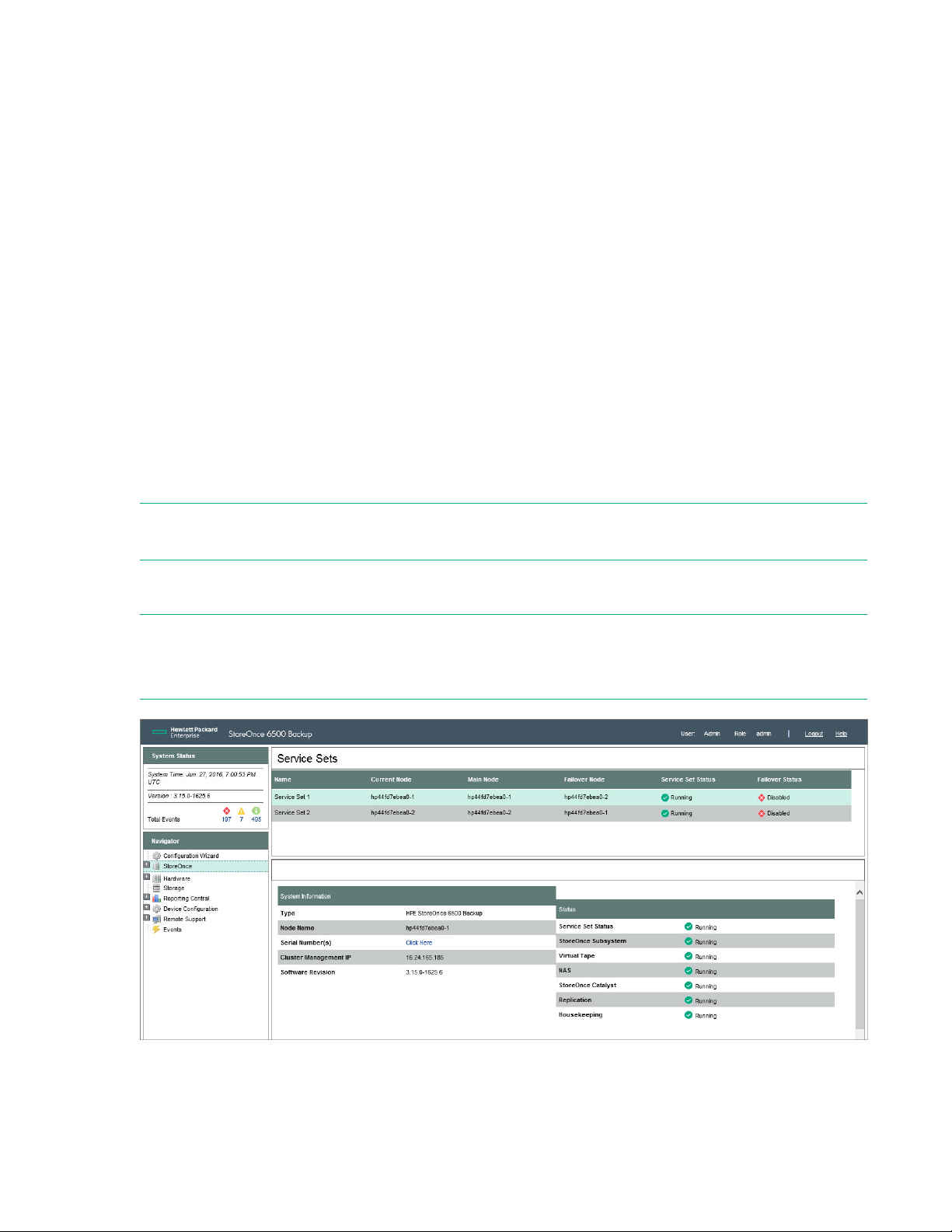
Overview of the StoreOnce System page
The initial page at GUI logon provides important information about system status and processes that are
running. The StoreOnce System page also provides access to individual StoreOnce functions, which are
available as sub topics (click + to display them in the Navigator).
System Information
The System Information section of the Status page provides information unique to an individual
StoreOnce System.
12 Overview of the StoreOnce System page
Page 13

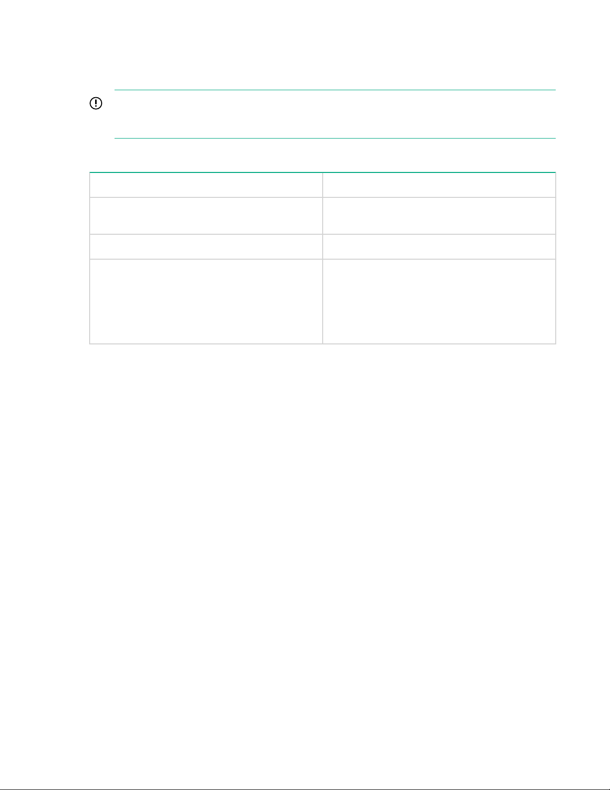
Table 1: System information parameters
Parameter Description
Type The model of StoreOnce System.
Node Name The node name for this Service Set.
Serial Number The serial number of the entire cluster. Use this serial number when
contacting Hewlett Packard Enterprise Support. (It is the same as the serial
number on the License management on page 188 page.)
Cluster Management IP The IP address that provides access to the StoreOnce Management Console
(GUI and CLI) and applies to the whole cluster, not individual couplets.
Software Revision The software revision of the node on which the Service Set is running. Use
this revision when adding couplets to check that all Service Sets are running
the latest and the same software.
Data VIF IPs The Data VIF IP addresses for data. Use these addresses when configuring
backup applications to send data to the StoreOnce System. The IP
addresses can be IPv6 or IPv4 addresses.
If VLAN tagging has been configured on your network, a scrollable list allows
you to see all the VLAN IP addresses that have been configured. For more
information about VLAN tagging, see the installation planning and preparation
guide for your product.
Status
The Status provides details about the rolled-up status of the system or Service Set and the status of the
services running.
Table 2: Status parameters
Parameter Description
Service Set or Overall
Status
StoreOnce Subsystem The status of the background support processes such as Event Manager and
Virtual Tape The status of the VTL service.
NAS The status of the NAS service.
StoreOnce Catalyst The status of the StoreOnce Catalyst service.
Replication The status of the Replication service.
Housekeeping The status of the Housekeeping service.
The state of the system or service set.
Resource Manager.
Storage Usage
Getting started 13
Page 14

The Storage Usage provides details about the amount of data on the system.
Table 3: Storage Usage parameters
Parameter Description
User Data Stored The amount of data written by the backup application (before deduplication)
to all stores on that service set.
Size On Disk The amount of disk space used to store the data deduplicated in all stores on
that service set.
Deduplication Ratio The deduplication ratio.
Capacity Saved The amount of capacity saved (as a percentage) by deduplicating the data.
Viewing service set information
On the lower StoreOnce main page, the screen displays parameters specific to service sets:
• Click on a service set to display status information for the services running on that set.
• Click on any column heading to change the sort order or select which columns are displayed.
• A single-couplet configuration has two Service Sets and is the minimum configuration. Additional
couplets increase Service Sets, two for each couplet, up to a maximum of eight. The following
example shows a configuration with eight Service Sets. Therefore, it has four couplets.
Table 4: Service set parameters
Field Description
Name The name of the Service Set.
Current Node The node on which the Service Set is running. This node is normally the Main
node, unless a failover state has been invoked.
Main Node The name of the node on which the Service Set normally runs.
Failover Node The name of the failover node for the Service Set.
Service Set Status The status of the Service Set, such as: Running, Starting, Fault, Not Started,
Stopped, or Unknown.
Failover Status The failover status of the Service Set. The three possible values for each
service set are: Enabled (green), Disabled (white X), and Failed Over (red).
This field is useful when running software upgrades or after a reboot to check
the failover status of Service Sets.
Select service set
A service set is a collection of various services, such as VTL, NAS, Replication, and StoreOnce Catalyst.
There is one instance of each service per service set. The auto-configuration process registers and starts
a service set by launching a process on the server for each of the services.
14 Viewing service set information
Page 15
Administrators can create elements such as libraries, NAS shares, replication mappings, and StoreOnce
Catalyst stores for a service set. They can also expand or contract the service sets that make up a
Federated store. When creating or modifying such an element, the system prompts you to select the
target service set to which it relates.
IMPORTANT: The number of available service sets depends on the number of couplets in the
cluster configuration. The minimum is 2 (for a single couplet in one rack), the maximum is 8 (for a
two–rack installation with four couplets).
Table 5: Select Target Service Set parameters
Parameter Description
Name The name of the Service Set. There are two for
each couplet in your cluster configuration.
Status The status of the Service Set.
Available <devices> Remaining This column is displayed when you create a library
or share and indicates how many devices you can
still create for this service set. The maximum
devices available depends upon the number of
couplets in your configuration. The maximum is 48
for a single couplet.
Why are there two service sets for each couplet?
There are two service sets for each couplet installed in the StoreOnce System rack to ensure resilience
and failover. Each Service Set has a VIF associated with it. This VIF is the IP address used to configure
replication mappings and StoreOnce VTL, NAS, or StoreOnce Catalyst devices as backup targets in the
backup application.
Each node in a couplet can run both service sets during a node failure, and each service set has its own
set of service processes and storage. Each service set is associated with:
• A primary node, the node on which it usually runs.
• A secondary node, where it will run if the primary node fails.
Each node can act as the secondary node for the main Service Set on the other. During a failover, the
service set moves transparently from the primary node to the secondary node. Because each storage
cluster in the couplet has two connections, one from each node, the service set can still access storage
on the primary node even though it is now running on the secondary node.
Getting started 15
Page 16

StoreOnce System models
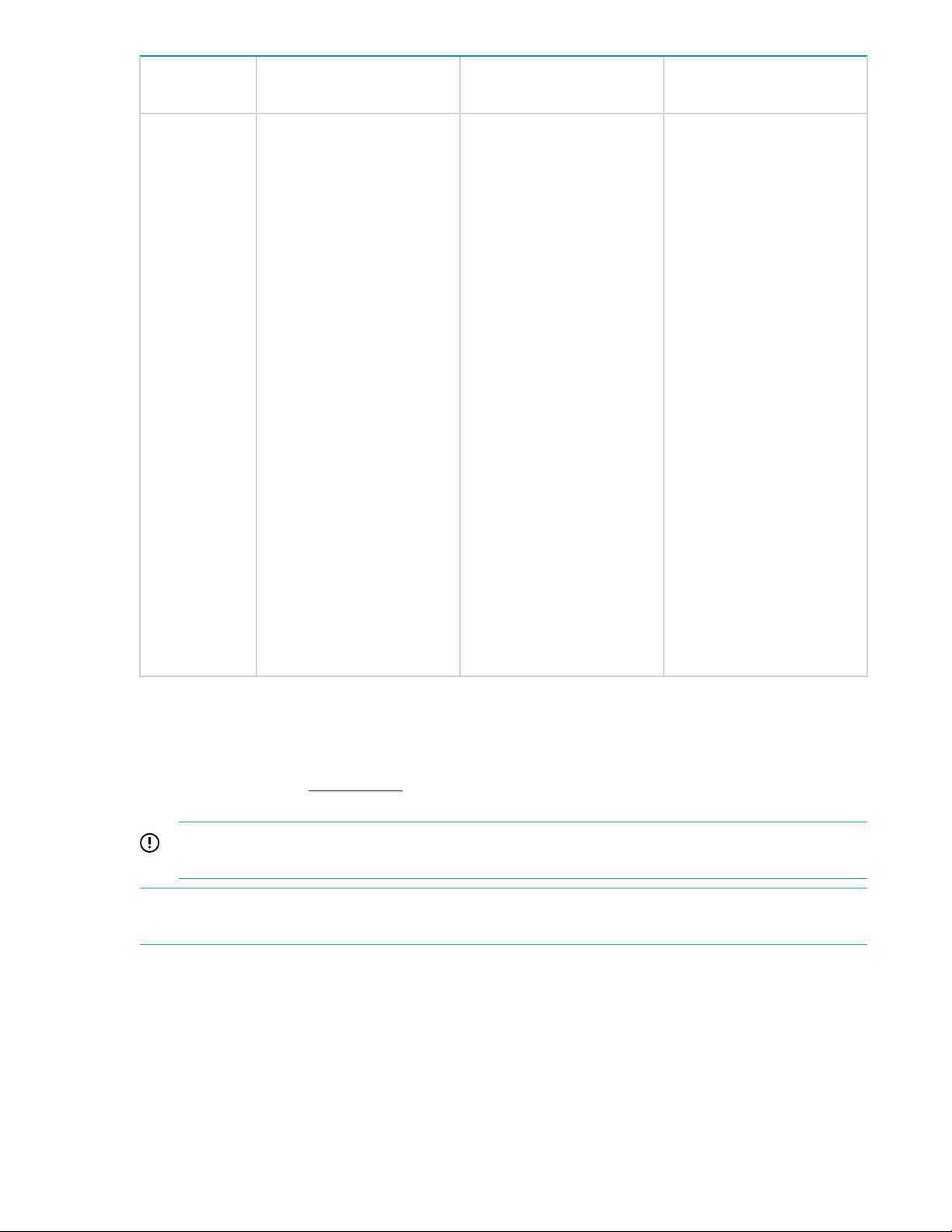
Table 6: Overview of StoreOnce Systems
Model Base Storage Capacity Storage Expansion
Options
StoreOnce
6500 System
Each couplet consists of
two server nodes and two
disk enclosures, each with
an initial 44 TB of
preconfigured storage
There are two options for
expanding storage:
• StoreOnce 6500 System
Capacity Upgrade Disk
Pack:
The StoreOnce 6500
System (88 TB)
Capacity Expansion kit
is a pack of twenty-two 4
TB disks, which are
added to the original
disk enclosure
A maximum of five of
these kits can be used
with the first enclosure
until all disk bays are
full.
• StoreOnce 6500 System
Capacity Upgrade
Enclosure with Disks:
Optional Hardware
Not supported
If adding a StoreOnce 6600
couplet to a 6500 cluster, 2
x 8 Gb Fibre Channel cards
must be installed in the
Optional Hardware PCI-E
slots of each node of the
StoreOnce 6600 couplet.
StoreOnce
6600 System
Each couplet consists of
two server nodes and two
disk enclosures, each with
an initial 44 TB of
preconfigured storage
Once all bays in the disk
enclosure are full, it is
possible to add a
couplet to your
StoreOnce 6500
System.
This task is performed
by Hewlett Packard
Enterprise service
engineers.
There are two options for
expanding storage:
• By adding disks to both
disk enclosures in a
couplet (StoreOnce
6600 System 88 TB
Capacity Expansion):
This expansion kit
contains twenty-two 4TB
Supported
Two PCI-E slots in each
server in a couplet available
for Optional Hardware
(these slots must be
installed in pairs and you
must install the same type
in each server in a couplet):
– 10 GbE SFP Network
cards
16 StoreOnce System models
Page 17
Model Base Storage Capacity Storage Expansion
Options
Optional Hardware
disks, which are added
to the original disk
enclosures in the
sequence described in
this guide. A maximum
of five of these kits can
be used with each
couplet until all disk
bays are full in both disk
enclosures.
• By adding couplets to
the cluster (StoreOnce
6600 120TB 2nd/4th
Couplet and/or
StoreOnce 6600 120TB
3rd Couplet):
Once all bays in both
enclosures connected to
a couplet are full, it may
be possible to add a
couplet to your HPE
StoreOnce 6600
System. The maximum
cluster configuration
accommodates four
couplets.
– 8 Gb Fibre Channel cards
– 16 Gb Fibre Channel
cards
Powering on
To power on the appliance, you must use the StoreOnce CLI and/or power on buttons. You can shut down
or reboot the appliance using either the StoreOnce CLI or the StoreOnce Management GUI on the
Maintenance page. See Maintenance on page 187 for more information about using the StoreOnce GUI
for power off options.
IMPORTANT: It is best to failover a service set during the node power on or reboot sequence in
case of unexpected errors with the node.
NOTE: If network switches and storage enclosures have been powered off, power on those first (using
the power on switches).
After maintenance activities, both servers must be powered on at the same time so that the checks in the
code can complete before the file system starts.
Procedure
1. Power on the servers using either:
Powering on 17
Page 18

• The power on button on each server to trigger a cold boot and automatically power on.
• StoreOnce CLI commands to power on a node remotely. (This method requires a server node that
is running.) For example, if a node was powered off using CLI commands, power it up again using
the following CLI command:
hardware powerup nodeX
2. After a successful power on, ensure that failover is enabled.
• To check the status of failover:
hardware show node status
• To enable failover if it is off:
system enable failover
3. Once failover is enabled, check that no service sets have failed over during any reboot sequence:
• To check the status of the service sets:
hardware show node status
NOTE: You can also use the GUI to check the status. Look at the StoreOnce System page of the
GUI and check the failover status of the service set.
• To fail them back:
system failback setX
NOTE: You can also use the GUI to failback a node. Locate the node in the Hardware pages of the
GUI and click Failback this server.
If power on is unsuccessful
IMPORTANT:
A previous unclean shutdown will lead to integrity checking of the storage and your user data.
Depending upon the amount of data stored on the couplet, this process can take several hours. Be
patient to see whether the Service Set will come online without further intervention or reboot.
If node or a couplet fails to successfully power on after a node experienced an unclean power off, power
off both nodes in the couplet (using the power buttons on the nodes if necessary). Power on one node
and then power on the other node in the couplet.
Powering off using the StoreOnce CLI
Various commands exist to shut down a node or a cluster. Use the correct command to perform the task
required. More details can be found in the StoreOnce System CLI Reference Guide.
NOTE: A power off command only powers off the server component. If the maintenance activity requires
the disk enclosure or internal network switch to be powered off, power them off manually.
18 If power on is unsuccessful
Page 19

• system shutdown: This command gracefully shuts down the cluster by shutting down all services
and StoreOnce service sets before powering down the servers. when you power up, the deduplication
stores will start up from a clean state. Servers will be in the off state, and will require powering on via
the power button.
• hardware poweroff nodeX: This command uses the iLO port to turn off the server, which does not
allow StoreOnce service sets to shutdown gracefully. Deduplication stores shut down in an unclean
state and require integrity checking (an automatic process) on the next power on. To avoid this
condition, the service set on a given node should be failed over to the backup node using the system
failover setX command before powering down the node.
Rebooting the system using the StoreOnce CLI
More details can be found in the StoreOnce System CLI Reference Guide.
Use the following CLI commands to reboot your system:
• system reboot: This command gracefully reboots the cluster by shutting down all services and
StoreOnce service sets before rebooting the servers. This means on reboot the deduplication stores
will start up from a clean state.
• hardware reboot nodeX: This command uses the iLO port to reboot the server, which does not
allow StoreOnce service sets to reboot gracefully. The result is deduplication stores shutting down in
an unclean state and requiring integrity checking (an automatic process) on reboot.
The following sequence is recommended if you wish to reboot a node in a controlled way. It fails over the
service set before rebooting the node.
1. system enable failover
2. system failover setX
3. system reboot nodeX
Once nodeX has completed reboot, use system failback nodeX.
Rebooting the system using the StoreOnce CLI 19
Page 20
VTL (Virtual Tape Libraries)
VTL Licensing requirements
• No licensing is required for VTL emulations unless using the Security features Data at Rest
Encryption, Data in Flight Encryption, and Secure Erase.
• VTL (or NAS) replication requires a license on the target site, but only if replication is used.
VTL replication requires a replication license per couplet, for each couplet in the appliance.
• Replication encryption using IPsec is part of the Security license. See
subnet.
Viewing the VTL configuration
Select VTL from the StoreOnce System Navigator menu to display the current VTL configuration.
The following functions are available from the StoreOnce–VTL page:
• VTL configuration, which allows an administrator to manage the interface settings for libraries.
• Library and cartridge management.
NOTE: Equivalent StoreOnce CLI commands are available for the tasks described in this section. See the
StoreOnce System CLI Reference Guide.
The top half of this page displays available service sets. Click on the service set to display the Fibre
Channel Settings tab for the VTL devices configured for that service set in the lower half of the page.
Viewing the Fibre Channel settings
If your system supports a Fibre Channel interface, navigate to StoreOnce > VTL > Fibre Channel
Settings tab.
To add encryption to a
Table 7: Fibre Channel settings
Setting Description
Port Index Libraries can be configured to use the ports in various combinations. See
Port Location The physical location of the Fibre Channel port—The PCI-E card slot number
Status The status of each port, which may be OK, Down, Warning, Error, or Not
20 VTL (Virtual Tape Libraries)
Creating a library on page 28 for more information.
that the card is in, and then the physical port number. For example, HBA-6
Port1.
Used. Warnings occur if the port is not available or is down. They also appear
if the system is unable to obtain Speed information. Errors occur if there is a
fault or the system cannot obtain the link status.
Table Continued
Page 21
Setting Description
Speed The default is Auto, which is the recommended option. The speed will be
auto-negotiated between the switch and StoreOnce appliance to choose the
highest supported speed. For users who wish to fix the speed, other values
are available, as follows: 16Gbs, 8Gbs, 4Gbs, or 2Gbs (not recommended).
Topology The default is N_Port, when a single target device creates many virtual
devices on a fabric attached port. N_Port requires the switch port to support
NPIV (N_Port ID Virtualisation).
Beacon Individual ports can be “beaconed” via the GUI. This toggles an LED on the
physical HBA. The color of this button changes to show the current status of
the beacon; grey is off, blue is on.
Editing the Fibre Channel settings
Prerequisites
Only administrators can edit the Fibre Channel settings.
Procedure
1. Navigate to StoreOnce > VTL > Fibre Channel Settings tab.
2. Click Edit to make the fields configurable for each port.
3. Make the preferred changes to the speed and/or topology, and click Update.
CAUTION: This update resets the Fibre Channel link and may affect any backup or restore jobs
running.
NOTE: Fibre Channel settings apply to the whole appliance. The settings can also be edited in the
StoreOnce Catalyst section of the GUI if you are backing up to StoreOnce Catalyst target devices over
Fibre Channel. Fibre Channel settings, defined on either page, apply to all target devices being
backed up over Fibre Channel. Therefore, any changes here will also apply to StoreOnce Catalyst
target devices over Fibre Channel and conversely.
Changing the port speed causes the port status to be reported as Down; refresh the VTL Configuration
page to verify that the port is back online. Check the Hardware Tree and the Events page to see the
change.
4. Click Continue at the warning prompt to continue applying the changes.
Changes affect all service sets running on the node.
Port assignment for StoreOnce Systems with multiple Fibre Channel ports
When creating a library, you can select one or multiple Fibre Channel ports for the Library controller
virtual robotics interface. The Fibre Channel settings identify both the HBA card and the port number that
will be used. For example, HBA-6.Port1 is Port 1 on the Fibre Channel card in slot 6.
Editing the Fibre Channel settings 21
Page 22

Drives within a virtual library can only appear on one Fibre Channel port. If you select multiple ports for
the library robotics controller, the drives are automatically distributed evenly across the ports to ensure
best performance and failover. After creating the library, it is possible to change the drive assignments
using the edit function on the Interface Information tab for the selected library. See Viewing the Interface
Information on page 32.
Disabling library Auto Creation
By default, a new library is automatically created every time a new server first connects to the StoreOnce
System using the iSCSI initiator.
Prerequisites
Only administrators can disable or reenable library Auto Creation.
Procedure
1. Navigate to StoreOnce > VTL > iSCSI Settings tab.
2. Click Edit .
3. Uncheck Auto Creation Enabled.
You can reenable the feature at any time.
Viewing the libraries list and library details
Procedure
1. Expand StoreOnce on the navigation tree.
2. Navigate to VTL > Libraries.
3. Select a library to view the library details.
• To sort the list according to a column, click on the column heading and select Sort Ascending or Sort
Descending.
• To hide or show columns, click on any column heading, select Columns and uncheck or check the
preferred columns.
• Users with an administrator login may also create libraries. Click Create. See Creating a library on
page 28 for more information.
• Users with an administrator login may edit details on some of the tabs for individual libraries (not all
tabs have editable information). The relevant GUI buttons are on the tab. For example, each Edit
button triggers the edit mode only for the current tab. When in edit mode, each tab has its own Update
and Cancel buttons. If you change tabs while in edit mode, a warning dialog advises that any changes
they have made will be lost.
The Delete button is on the Device Details tab only and will delete the entire library.
22 Disabling library Auto Creation
Page 23

Library and device details parameters
Library parameters (top half of page)
Table 8: Library parameters
Parameter Description
Name Identifies the selected device (library). Hewlett Packard Enterprise
recommends using a name that identifies the host or backup job with which it
is associated.
Replication Role The role of the library, which may be non-replicating, replication source or
replication target.
Status The status of the library, which may be online, offline, not started, failed to
start, stopping, creating, port not present, or deleting.
Connection Indicates whether the library is connected. Possible values are: Connected –
A client device is connected to any device (robotics or drive) within this
library. Not Connected – No device is connected to this library.
Device Type The emulation type used by the backup software. It is selected when you
create a device.
Cartridges/Slots The number of cartridges or slots available on the device, which is
determined by the Emulation Type selected when the device was created;
see Emulation types for tape devices on page 30. You can reduce the
number of slots in the Device Details tab for a library selected on this page,
but this reduction only removes the highest empty slots. Once it reaches a
slot number that contains data, you cannot reduce the number further on this
page, even if earlier slots are blank. First use the Cartridges tab to make the
slot empty.
Port Identifies the port to which the host is connected for backup and restore. The
number of ports available in the drop-down menu depends upon the
interfaces that your model supports and your network configuration.
User Data Stored The amount of user data stored on the library.
Size On Disk The actual size used on disk (after deduplication).
Dedupe Ratio The deduplication ratio achieved on the data on the library. If deduplication is
disabled, the column displays “Dedupe Disabled.”
Service Set The service set to which the library belongs.
Device details parameters (bottom half of page)
The Device Details tab displays device-specific information for the selected library.
Users with an administrator login may perform the following tasks from this tab:
Library and device details parameters 23
Page 24
• Creating a library (administrators only)
• Editing library details (administrators only)
• Deleting a library (administrators only)
• Make Replication Target libraries visible to the host
Table 9: Device Details parameters
Field Description
Basic Details
Library Name The name used to identify a particular library. Enter a name that identifies
the host or backup job with which it is associated.
Creation Time The date the library was created is generated automatically.
Media Changer Port
Deduplication Enables deduplication if the check box is selected (default); unselect to
Encryption Enabled Enables encryption of data stored in the library. This feature requires a
Secure Erase Mode Enables Secure Erase. This feature requires a StoreOnce Security pack
Identifies the port type (for example, Fibre Channel).
create a non-deduplication library. Deduplication cannot be enabled or
disabled once the library is created.
StoreOnce Security Pack license before encryption can be enabled.
Encryption cannot be enabled or disabled once a library is created; it can
only be enabled at library creation. If enabled, encryption is performed
before writing data to disk for this library.
license before it can be enabled. To enable, select the number of preferred
Overwrite Passes for deleted data (1, 3, 5, or 7 — The default selection of
“None” disables secure erase).
You cannot select Secure Erase while creating a library, but after the
library is created, you can activate this feature if you have a Security pack
license.
See Security features for information about the Secure Erase feature.
Table Continued
24 VTL (Virtual Tape Libraries)
Page 25

Field Description
Physical Data Size Quota This quota is for the amount of data written to disk after deduplication. The
minimum quota size is 50 GB. If the quota is enabled and the quota limit is
reached, backups will fail to prevent the quota from being exceeded. The
quota allows you to partition the physical capacity of the appliance
between various users.
NOTE: If capacity management is required, Hewlett Packard Enterprise
recommends configuring backup applications with quotas to reroute to
another device or to postpone backups to prevent backups from failing
unexpectedly.
When a library reaches its quota, the status of the library will change to
“Critical”. Restores from that library are permitted but new backups will
fail. When the quota is no longer met, either by increasing the quota or by
expiring backups, the library status returns to the “OK” state.
Logical Data Size Quota This quota is for the amount of data a user sends to the device before
deduplication. The minimum quota size is 50 GB. If the quota is enabled
and the quota limit is reached, backups will fail in order to prevent the
quota from being exceeded. This allows you to provide a service to back
up a particular amount of user data. For example, set this quota when you
charge customers per TB of user data protected.
NOTE: If capacity management is required, Hewlett Packard Enterprise
recommends configuring backup applications with quotas to reroute to
another device or to postpone backups to prevent backups from failing
unexpectedly.
When a library reaches its quota, the status of the library will change to
“Critical”. Restores from that library are permitted but new backups will
fail. When the quota is no longer met, either by increasing the quota or by
expiring backups, the library status returns to the “OK” state.
Emulation
The StoreOnce appliance supports HPE and IBM Library and drive emulations.
Library Emulation The emulation type of the library. The StoreOnce System supports a
number of emulation types.
See also Emulation types for tape devices on page 30. The emulation
type determines the available embedded drives and cartridge slots. For
example, if you select MSL G3 Series (2x24), the device emulates an MSL
2024 Library with two embedded tape drives and a possible total of 24
cartridge slots. Consult your backup application technical support
information for information about device types they support.
Table Continued
VTL (Virtual Tape Libraries) 25
Page 26

Field Description
Default Drive Emulation The drive emulation type, LTO–2, 3, 4, 5 or 6, determines the default
capacity of the newly created cartridges within the library device. Tape
cartridge capacities can be changed individually at any time but cannot be
reduced to smaller than the current used size.
If you selected D2DBS Generic for the Library Emulation, Ultrium VT is an
option for drive emulation. This is a generic Ultrium device which is clearly
identifiable as virtual. Where supported by the backup application, Hewlett
Packard Enterprise recommends that D2DBS Generic and Ultrium VT are
used in preference to the other emulation types.
All drives on a library configured with the IBM-TS3500 emulation type will
use the IBM-LTO3 drive emulation type. Drives on a library configured with
IBM-TS3500 IBMi will use the IBM-LTO5 drive emulation type. If the library
is then changed to a different emulation type, the drives will change to the
default drive emulation type of LTO4.
If you edit this field, the new setting applies only to the next drives that are
created within the library, it is not retrospectively applied to existing drives.
Number of Cartridge Slots Define the number of cartridge slots in the library. The number of slots
available depends upon the Emulation Type selected. Each slot is
automatically populated with a new cartridge upon creation. The cartridge
capacity corresponds to the Drive Emulation type.
Number of Drives The default number of drives is determined by the Emulation Type
selected. If increasing the number of drives, DO NOT exceed the
maximum number of libraries and drives that a host can physically access.
The number of drives can only be edited during library creation from this
field. After library creation, there is a separate button to add and remove
drives.
See Key Parameters on page 247 for detailed specifications.
Cartridge Size The size of the cartridge in GB. This field is only available during creation
of the cartridge.
See Key Parameters on page 247 for detailed specifications.
Number of Barcode
Characters
Enables the barcodes for the library to display six or eight characters. The
StoreOnce System generates barcodes automatically for cartridges. When
entering a barcode manually, eight characters are required. If the 6–
character barcode is selected, the StoreOnce System will truncate to six
characters, removing two characters of an 8–character barcode. For
example, barcode 1ABCDEFG will truncate to BCDEFG. The barcode is
displayed with the truncated characters in brackets on the Cartridges tab,
(1A)BCDEFG.
Table Continued
26 VTL (Virtual Tape Libraries)
Page 27

Field Description
Barcode Template Enabled Enables configuration of the barcodes. A barcode is an 8– or 6–character,
alpha-numeric, unique identifier for a cartridge within the StoreOnce
System. The backup application will normally track cartridges using
barcodes but may also alias the cartridge with another name in its
database. (IBM emulations only support 8–character barcodes.)
By default, barcodes are generated automatically but may be determined
by a barcode template created when the library is created. If using
barcode templates, the barcode template:
• Must be unique and must not start with the letters “CLN” or “DG”
because these combinations are reserved designations for cleaning
and diagnostic cartridges.
• Can have a prefix of up to three alpha-numeric characters, a start
value, and a suffix of up to two alpha-numeric characters.
Any unspecified prefix or suffix characters will increase the length of
the variable field of the barcode.
• Should be a minimum of 6 characters. Valid ASCII characters are A-Z,
a-z, 0–9. Barcodes are always displayed as eight characters with
letters in capitals on the StoreOnce Management GUI and CLI (padded
with space characters) regardless of the size selected. However, if the
number of barcode characters is set to 6, only the rightmost six
characters will be visible to the backup software, that is, barcode
1ABCDEFG will truncate to BCDEFG. (Truncated barcode characters
are shown in brackets in the Cartridges tab.)
You can modify the barcode template after library creation by clicking
Modify Barcode Template on the Device Details tab.
iSCSI Information
This section only applies to iSCSI libraries.
Fibre Channel Information
This section applies to all products that support optional Fibre Channel cards.
PCI-E Slot # Lists the PCI Slots
Table Continued
VTL (Virtual Tape Libraries) 27
Page 28

Field Description
Slot configuration,
availability
Library Usage (all models)
Backup Application The backup application primarily used to back up to this library. This
Backup Data Type The type of data being protected by the backups to this library. This
Shows slot configuration or availability. Status can be:
• Optional slot: The PCI-E slot is open. With a Fibre Channel Controller
expansion license, you can add an additional Fibre Channel Controller
card to this slot.
• Not available: The PCI-E slot is not available to use for an optional
Fibre Channel card
• For licensed and activated Fibre Channel cards, shows the Fibre
Channel ports and checkboxes for each port. For example, if you have
installed a Fibre Channel card in PCI-E Slot 6, you will see HBA-6
Port2 (#2) and HBA-6 Port1 (#). Use the checkboxes to select which
ports you want to use depending on your system configuration.
optional, but recommended, field is provided to assist with support
troubleshooting and has no impact on performance or deduplication
efficiency.
optional, but recommended, field is provided to assist with support
troubleshooting and has no impact on performance or deduplication
efficiency.
Creating a library
HPE recommends the following to avoid complication when configuring the backup application, and also
to avoid creating additional Fibre Channel SAN traffic:
• Only configure the libraries that you need.
• Only configure the number of cartridges that you are likely to need.
You can add cartridge slots at a later date to expand the system and remove individual blank cartridges
from a library without deleting the whole library.
The maximum number of virtual devices supported varies according to the product and this number is
split across VTL, NAS, and StoreOnce Catalyst devices. See Key Parameters for more information.
Prerequisites
Only administrators can create libraries.
Procedure
1. Navigate to StoreOnce > VTL > Libraries
2. Click Create in the upper left corner of the screen.
3. Select a service set for the new library and click OK. The information on the service set identifies how
many libraries are still available.
28 Creating a library
Page 29
4. Enter the appropriate information; see Library and device details parameters on page 23.
To enable Data at Rest or Data in Flight Encryption for the new library, configure it at this time by
checking the Encryption Enabled box. This feature requires a license. If the license is not installed, an
information message is displayed next to the check box stating Not Licensed. See Security features
and License management for more information.
NOTE: The Replication Wizard does not allow creation of an encrypted target library. If a replication
target library needs encryption enabled, you must create the library on the target appliance before
replication mapping to it.
5. Click Create.
The Cartridges tab is only generated after the library is created. The information on the Interface
Information tab is generated automatically.
NOTE: Once the library has been created, you can enable Secure Erase.
Deleting a library
Prerequisites
Only administrators can delete libraries.
Procedure
1. Navigate to StoreOnce > VTL > Libraries.
2. Select a library from the Libraries list.
3. Click Delete on the Device Details tab.
WARNING: All data on the device will be deleted. The library's deduplication store is also
deleted. It may take some time to delete all the files and free space on the StoreOnce System. If
Secure Erase is enabled for this store, this data will be deleted securely.
Editing library details
Prerequisites
Only administrators can edit library details.
Procedure
1. Navigate to StoreOnce > VTL > Libraries
2. Select a library from the Libraries list.
3. Click Edit on the Device Details tab.
4. Amend details as appropriate.
Deleting a library 29
Page 30

CAUTION: Take care when changing the Port configuration because the system does not
automatically reassign any drives that may now be configured incorrectly. For example, if you
change from a multiple Fibre Channel port configuration to a single Fibre Channel port, manually
correct those drives that are connected to the wrong port when the status shows ready and
restarted. See Viewing the Interface Information on page 32.
5. Click Update.
Notes:
It is possible to edit some, but not all, device details after creating a library.
• Delete cartridges by reducing the number of slots on the Devices page. This reduction will only
remove the highest-numbered empty slots. Once the Delete operation reaches a slot number that
contains a cartridge, it will not allow further reduction on the Details page, even if previous slots are
empty. To open previous slots, first use the Cartridges tab to delete the cartridge from the slot.
• Changing the cartridge size (by changing the emulation type) on this page will only change newly
added cartridges; it does not change the size of cartridges that were already created.
• You can reduce the number of drives but, if you go to 0, the port setting will change to "No Port".
The Number of Drives field can only be edited during library creation. After library creation, there is a
separate button to Add/Remove drives.
• You cannot change the library type to a type that has a smaller set of maximum values (for example,
the number of cartridges).
• You cannot enable or disable deduplication.
• Once the library is created and the correct license is applied, the Secure Erase Mode box appears on
the Device Details tab. The selection box defaults to None, meaning Secure Erase is disabled. To
enable Secure Erase, select the preferred number of Overwrite Passes (1, 3, 5, or 7). If enabled, this
feature allows you to securely erase confidential data that may have unintentionally been backed up
as part of a regular backup job. See Security features on page 199 and License management on
page 188 for more information.
Adding and removing drives
Procedure
1. Navigate to StoreOnce > VTL > Libraries
2. Select a library from the Libraries list.
3. Click Add/Remove Drives on the Device Details tab.
4. Edit the number of drives.
5. Click OK.
Emulation types for tape devices
StoreOnce Systems emulate a range of physical tape devices.
30 Adding and removing drives
Page 31

D2DBS Generic
If supported by your backup application, this is the preferred emulation type because it does not
emulate any physical library types in existence and is, therefore, clearly identifiable as a StoreOnce
device. It is the most flexible emulation type available; however, backup application support varies by
software vendor.
If you have selected D2DBS Generic for the Library Emulation Type, you will be able to select Ultrium
VT for the drive emulation. This is a generic Ultrium device which is clearly identifiable as virtual.
Backup application support for Ultrium VT is common, but not as complete as the D2DBS library type,
so it is not possible to use it with all backup software.
NOTE: VERITAS prefers their customers use this emulation type with BackupExec and Netbackup.
EML E Series
An enterprise tape library solution that allows you to configure drives per node and cartridges per
library.
ESL E Series
An enterprise tape library solution that allows you to configure drives per node and cartridges per
library.
IBM-TS3500
A tape library device that appears as a native IBM TS3500 device in a TSM environment to allow use
of standard IBM drivers. The emulation type is configured at the library level. Therefore, all drives on a
library configured with the IBM-TS3500 emulation type will use the IBM-LTO3 drive emulation type. If
the library is then changed to a different emulation type, the drives will change to the new emulation
type.
IBM-TS3500 IBMi
The IBM-TS3500 IBMi is a tape library device that appears as a native IBM TS3500 IBMi device in a
TSM environment to allow the use of standard IBM drivers. The emulation type is configured at the
library level. All drives configured with the IBM-TS3500 IBMi emulation type will use the IBM-LTO5
drive emulation type. If the library is then changed to a different emulation type, the drives will change
to the new emulation type.
MSL G3 Series (2x24)
A tape library device with a maximum of two embedded Ultrium tape drives and 24 cartridge slots.
Used when implementing rotation schemes which involve simultaneous backup jobs to two devices.
This emulation type is widely supported by backup applications.
MSL G3 Series (4x48)
A tape library device with a maximum of four embedded Ultrium tape drives and 48 cartridge slots.
Used when implementing rotation schemes which involve simultaneous backup jobs to more than two
devices or those that use a large number of cartridges devices. This emulation type is widely
supported by backup applications.
MSL G3 Series (8x96)
A tape library device with a maximum of eight embedded Ultrium tape drives and 96 cartridge slots.
Flexible emulation
The ESL, EML and D2DBS emulations are flexible because they allow you to configure a large number of
drives per library. The main benefits are that a large number of drives allows:
VTL (Virtual Tape Libraries) 31
Page 32

• More concurrent streams on backups which are throttled due to host application throughput, such as
multi-streamed backups from a database.
• A single library (and therefore deduplication store) to contain similar data from backups that must run
in parallel to increase deduplication ratio.
If using these flexible emulation types, consider the following factors:
• An important consideration when configuring VTL devices is that the library and each drive that you
configure for it counts as a separate device. There are practical limitations on the number of devices
that each host and Fibre Channel switch or HBA can access. See Key Parameters on page 247 for
detailed specifications.
• The total device value also applies to NAS shares and StoreOnce Catalyst stores. If you configure the
full value as VTL devices, you will not be able to configure any NAS shares or StoreOnce Catalyst
stores for that appliance or service set.
Viewing the Interface Information
Navigate to StoreOnce > VTL > Libraries > Interface Information tab.
This tab shows interface information for the media changer and drives on the selected library. The
information for the Interface Information tab is generated automatically. HPE discourages manual
configuration.
Fibre Channel interface
The following information is provided for a device that is configured to use the Fibre Channel interface.
Some models do not support Fibre Channel.
You may use this tab to adjust the Fibre Channel port to which a drive has been assigned; see Changing
a drive assignment on Fibre Channel ports on page 33.
Table 10: Fibre Channel Interface Information
Field Description
Device Name Lists all of the devices for the specific Library. There are entries for the
Media Changer and for each of the drives configured.
Status The device status (not the state of the connection): Offline, starting,
stopping, online
Port Defines the Fibre Channel port to which each media changer or drive is
connected. See also Changing a drive assignment on Fibre Channel
ports on page 33.
Device Serial Number A unique serial number for the device. It is generated automatically by the
StoreOnce System and cannot be edited.
FC Address The Fibre Channel addresses of the device. This will show an address for
32 Viewing the Interface Information
each FC Port for which the device is configured, or "Down" if the port is
not connected.
Table Continued
Page 33

Field Description
World Wide Node Name Provided when the device is created and is globally unique. You can
change this, if necessary, but not to any names used by libraries or drives
on the local appliance.
World Wide Port Name Generated automatically by the StoreOnce System and used for Fibre
Channel zoning for Fibre Channel devices. You can change this, if
necessary, but not to any names used by libraries or drives on the local
appliance. Libraries split across multiple ports have multiple entries in this
field.
Number of Logins Fibre Channel libraries show the number of logins for each device in the
library. Libraries split across multiple ports have multiple entries in this
field.
Changing a drive assignment on Fibre Channel ports
This information applies only to units with Fibre Channel cards installed.
When creating a library, drives are automatically assigned based upon the specified port configuration. If
you select a pair of ports, the drives are distributed equally across both ports. To change a drive
assignment:
Procedure
1. Navigate to StoreOnce > VTL > Libraries
2. Select a library from the Libraries list.
3. Click Edit on the Device Details tab.
4. For each configured drive, select the required port from the drop-down list.
5. Click Update.
Viewing the cartridge information
Navigate to StoreOnce > VTL > Libraries > Cartridges tab.
This tab shows cartridge information for the selected library.
Changing a drive assignment on Fibre Channel ports 33
Page 34

Table 11: Cartridge parameters
Field Description
Location Identifies each element of the library available to hold a cartridge. The
types of elements are:
• Mail slot: a dedicated slot used to hold a cartridge that is ready for
exporting to or importing from physical tape. The Mail slot is not used
with StoreOnce models.
• Tape drive: populated when there is activity on a cartridge. You can
move a cartridge into a tape drive by using the Move Cartridge dropdown menu in Edit mode.
• Slot n: one of the standard library slots.
Barcode A barcode is an 8– or 6–character, alphanumeric, unique identifier for a
cartridge within the StoreOnce System. See Device Details tab for
barcode information.
Mapped Slot Check box indicates whether the slot is included in a replication mapping
configuration. It cannot be edited from this page.
Used Size The actual used capacity in MB or GB.
Max Size Defaults to the appropriate capacity for the drive emulation type selected
on the Devices tab. This value may be changed if the Used Size is Blank.
The maximum value allowed is 3200 GB.
Write Protected Check box that enables (checked) and disables (unchecked) write
protection, see Write protecting a cartridge on page 36.
Last Written Identifies when the cartridge was last written to and is useful when
identifying data for copying or exporting.
NOTE: Additional columns appear when function buttons are selected below, such as Create, Move, and
Delete.
Empty slots
Empty slots are slots containing no cartridges and all the fields are empty.
• Tape drive row: A library consists of two devices: a tape drive and changer device. This location refers
to the tape drive element of the library and is normally only populated when the backup application on
the host is writing to or reading from the library.
• Mail slot row: This location is the slot used for importing and exporting cartridges from a library. It is
provided by StoreOnce virtual libraries for compatibility with backup applications but is not used.
• Numbered slot row: This slot is empty after a
Delete
operation or after the backup application has moved data to the mail slot for export.
34 VTL (Virtual Tape Libraries)
Page 35

Once a numbered slot is empty, the Create button may be used to create a new blank cartridge; see To
create a cartridge (administrators only).
Creating a cartridge
NOTE: You can only create a cartridge in an empty slot.
Prerequisites
Only administrators can create cartridges.
Procedure
1. Navigate to StoreOnce > VTL > Libraries > Cartridges tab.
2. Click the Create button. In the Add Cartridge column, empty slots are checked.
3. Select individual slots by clicking the appropriate check boxes. After selecting the slots where
cartridges will be added, click Create.
4. Alternatively, click Create all to create a blank cartridge of the size/emulation type selected when the
library was first configured in all empty slots.
a. If you create a cartridge in an empty slot, the backup application must inventory it (add it to its
database or catalog) before the backup application can access the cartridge.
b. If you create a cartridge in an empty mail slot, use the backup application to move the blank new
cartridge to an empty cartridge slot without requiring an inventory. This saves processing time.
5. Restart the backup application services to see the new cartridges.
Deleting a cartridge
Things to know before you delete a cartridge:
• You cannot delete cartridges that are currently in drives, that are mapped for replication, or that are in
the delete pending, erase pending, or creating state.
• You can also delete cartridges by reducing the number of slots on the Devices page, but this only
removes the highest slots with no or blank cartridges. Once the Delete operation reaches a slot
number that contains a cartridge with data, it will not reduce the number further on the Details page
even if earlier slots are blank. First, use the Cartridges tab to reconfigure the slots to a blank state.
Prerequisites
Only administrators can delete cartridges.
Procedure
1. Navigate to StoreOnce > VTL > Libraries > Cartridges tab.
2. Click the Delete button in the bottom right corner of the page.
The Delete Cartridge column will appear.
Creating a cartridge 35
Page 36

3. To delete individual cartridges, select individual slots by clicking the appropriate check boxes in the
Delete Cartridge column.
4. Click Delete.
NOTE: A dialog is displayed, warning that all data will be lost and asking you to confirm the Delete
action.
If you click Cancel, the cartridges will not be deleted and you remain in delete mode. Click Delete to
continue and the selected cartridges will be deleted. The GUI does not differentiate between cartridges
with data and blank cartridges.
Deleting all or a range of cartridges
You cannot delete cartridges that are currently in drives, that are mapped for replication, or that are in the
delete pending, erase pending, or create state.
Prerequisites
Only administrators can delete cartridges.
Procedure
1. Navigate to StoreOnce > VTL > Libraries > Cartridges tab.
2. To delete all the cartridges in the library at once, click Delete All.
3. In the window that appears, choose from the following options:
a. Delete — Remove cartridges (default): completely deletes the cartridges
b. Erase — Erase cartridge data: deletes the data but leaves the cartridge configurations intact
4. You can also determine which cartridges to delete or erase:
a. All Cartridges
b. Range: enter the first and last slot to be included in the delete or erase.
5. Finally, if you select the “Delete cartridges with data” check box, cartridges containing data will be
deleted. If unselected, only blank cartridges are deleted. After all of the options are selected, click OK.
A confirmation box appears; click OK.
Write protecting a cartridge
Prerequisites
Only administrators can write protect cartridges.
Procedure
1. Navigate to StoreOnce > VTL > Libraries > Cartridges tab.
2. Click Edit for the selected library.
36 Deleting all or a range of cartridges
Page 37

3. Check the Write Protected check box for the appropriate cartridges.
4. Click Update. Your backup application will not be able to write any more data to the cartridges.
Editing the maximum cartridge size
The Max Size defaults to the appropriate capacity for the drive emulation type selected on the Devices
tab, but this value is editable. The maximum value allowed is 3200 GB.
The maximum size indicates the maximum amount of user data that can be written to that cartridge,
assuming uncompressed data; it will only be committed when data is written to it. Changing the maximum
space does not affect actual disk usage or save disk space but may be useful if you know you will be
moving data to a physical tape with a smaller cartridge capacity.
Prerequisites
Only administrators can edit the maximum cartridge size.
Procedure
1. Navigate to StoreOnce > VTL > Libraries > Cartridges tab.
2. Click Edit for the selected library.
3. Select a value from the drop-down menu, and click Update.
Moving or unloading cartridges
The move and unload options are useful to re-align the library configuration against the backup
application. For example, if the backup application has crashed or if the backup application does not
support the Move Medium command, the library and the backup application can become out of sync.
NOTE:
• You can move cartridges, but only to an empty Location (tape drive or numbered slot).
• You cannot move or unload cartridges that are in the delete pending, erase pending, or create state.
Procedure
1. Navigate to StoreOnce > VTL > Libraries > Cartridges tab.
2. Click the Move button. The Move Cartridge drop-down menu lists available empty slots. (Empty
numbered slots are created when a cartridge is deleted.)
3. Use the Unload all Cartridges button to return all cartridges to default slots.
Editing barcodes in bulk
After a library is created, the Edit Barcodes button appears at the bottom of the cartridges tab for that
library. This feature allows the barcodes of a batch of cartridges within the library to be changed according
to a user-defined template which may contain a fixed prefix and/or suffix value and a variable portion.
Barcode parameters to note:
Editing the maximum cartridge size 37
Page 38

• All characters within the barcode must be alpha-numeric (A-Z, 0–9). All alphabetic characters will be
capitalized upon application (regardless of how they are entered).
• A barcode template cannot be applied to a range of slots with one or more empty slots.
• A duplicate barcode detected within the service set prevents the barcodes from being updated. The
check stops at the first duplicate barcode rather than continuing to search for additional duplicates.
• A barcode template results in restricted barcode prefixes of CLN or DG being created.
Procedure
1. Navigate to StoreOnce > VTL > Libraries > Cartridges tab.
2. Click Edit Barcodes.
3. In the Batch Update Barcodes dialog box, configure the following:
• First Slot: Defines the number of the first slot in the library that will be with the batch.
• Last Slot: Defines the number of the last slot in the library that will be updated with the batch.
• Prefix: Defines the first letter or numerical value for the barcodes. Accepts up the three characters.
• Start Value: Defines the numerical value of the first barcode variable field.
• Suffix: Defines the suffix letter or numerical value for the barcodes. Accepts up to two characters.
IMPORTANT: The values chosen for prefix, suffix, and starting value will limit how many
barcodes can be generated. For example, if you enter a 3 character prefix and 2 character suffix,
you are limited to 3 alpha-numeric characters for the variable portion which limits the total
number of barcodes to 46656 barcodes if the starting value for the variable portion is 000. Note
that if 6 character barcodes are selected, the leading characters of the barcode will not be
reported to the backup application; these may be part of the barcode prefix specified.
After configuring the barcode fields, if red outlines appear on the Prefix, Start Value, or Suffix boxes,
then an error occurred. Change the values inside the indicated box or boxes. Mouse over a red
outlined box and a note pops up explaining the error. Clicking OK without clearing the indicated errors
prompts a pop-up window that references validation errors in the form, and the barcode update is not
applied.
4. Once all fields are correctly configured, click OK. The new barcodes are applied to the cartridge slots
that were chosen for update.
Making Replication Target libraries visible to the host
NOTE: See Replication functions on page 54 for more details on replication configuration.
Replication Target libraries are not normally visible to the host, but you can configure devices to make
them visible to backup applications. This allows the backup application to:
• Move cartridges from storage slots to drives in the library.
• Perform read and verify operations on the cartridge (but not write).
• Perform load/unload operations on the tape device.
38 Making Replication Target libraries visible to the host
Page 39

WARNING: Use with care. If the backup application can see both source and target libraries, the
application cannot distinguish between the source library and the target library because the
barcodes are duplicated in the two locations.
Why make target libraries visible?
It may be useful to make a target library visible to the backup application on the host to:
• Confirm that replication is working correctly and check the integrity of the replicated backup by doing a
test restore.
• Perform manual tape copy jobs (sometimes called tape offload) to any tape device on the network
using the backup application.
IMPORTANT: You cannot change data on a Target library cartridge; you may only load it temporarily
into a physical tape device to read it.
Best practices for using this feature
WARNING: Failure to follow best practices may cause instability and damage to your backup
system and data. Cartridges can be marked as unusable or the backup application can attempt to
write to target cartridges.
Procedure
1. Verify that no replication jobs to the selected target cartridge are in progress.
2. Verify that no backup jobs to the mapped source cartridges are scheduled.
3. Verify that the backup application media server instance to be used is not within the same cell/domain
that can access the source cartridge.
4. Import the data on the target cartridge into the backup application (this operation must be repeated
after each replicate operation to the cartridge).
5. Perform the desired operation on the cartridge, which may be:
a. Verify the cartridge using the backup application either with a verify command or by performing a
restore.
b. Copy the cartridge to a physical tape device connected to the media server.
Making a target device visible
• Create the replication mapping as normal. See Running the replication wizard (virtual tape
devices) on page 66, as appropriate.
• From the host that has access to the target library on the VTL — Libraries page, select the target
library in the Libraries list.
• Click Edit.
• The Port defaults to None. Select the appropriate Fibre Channel, depending on your system model
and configuration.
VTL (Virtual Tape Libraries) 39
Page 40

• Click Update.
• Make the target library visible from other hosts. Configure the Fibre Channel fabric to make the host
visible. Target visibility persists even if the power fails or if the replication mapping is removed.
To remove target visibility, reset the Port to None.
40 VTL (Virtual Tape Libraries)
Page 41

NAS functions
IMPORTANT: The StoreOnce network share is intended to be used ONLY by backup applications
that “back up to disk”. Do not use the NAS target device as a drag-and-drop general file store
unless using the NAS share to seed an appliance for replication.
NAS licensing requirements
• No licensing is required for NAS emulations unless using the supported security features, Secure
Erase and Encryption of Data at Rest.
• If NAS replication is used, a license on the remote target appliance is required. Self-replication does
not require a license.
Editing NAS shares
Procedure
1. Navigate to StoreOnce > NAS > Shares.
2. Select a share from the list.
3. To edit the share, click Edit on the bottom of the screen.
4. Make the necessary changes.
5. Click Update.
Viewing NAS shares and share information
Navigate to StoreOnce > NAS > Shares.
The top pane of the Shares page displays all configured shares (both CIFS and NAS) and provides a
summary of the different constants of the shares.
The bottom pane of the Shares page displays more details about the share selected in the Shares list.
Shares list
Item Description
Name The name that is used to identify the share configured
Replication Role The role of the share, which may be non-replicating, replication source, or
replication target
Status The status of the share, which may be online, offline, not started, failed to
start, stopping, creating, or deleting
Access Protocol CIFS or NFS
Table Continued
NAS functions 41
Page 42

Item Description
User Data Stored The amount of user data stored on the share
Size on Disk The actual size used on disk after deduplication
Dedupe Ratio The deduplication ratio achieved on the data on the share. If deduplication is
disabled, the column displays Dedupe Disabled.
Created Date/Time the share was created
Last Modified The last time the share has been modified
Service Set The service set on which the share is configured
Share tab
Item Description
Name The name that will be used to identify the share in Windows
Description A text description of the share (optional)
Access Protocol CIFS or NFS
Share Version Shares can be configured as version 2 (default) or version 1. The primary
difference is in the maximum number of items (where an item is a file or a
directory) per share permitted: 25,000 for version 1 shares and 1,000,000 for
version 2 shares.
In addition, version 2 shares have been optimized to improve performance
with Commvault backup software. Configuring a version 1 share is only
recommended for replication compatibility with another appliance on an older
software version that only supports version 1 shares.
Once configured, you can change the share version from 1 to 2 but you
cannot change from 2 to 1. The maximum number of shares depends upon
the product model and the number of other devices (including VTL libraries
and StoreOnce Catalyst stores) already created.
See Key Parameters on page 247 for detailed specifications.
Network Path The network path to access the configured share
Number of Files The number of files on the share. This information is also available as a
column at the top of the Shares page but is hidden by default. Click any
column heading to configure which columns display.
Number of Directories The number of directories on the share. This information is also available as
a column at the top of the Shares page but is hidden by default. Click any
column heading to configure which columns display.
Write Protection Used to prevent further backup to the share. If enabled, any backup jobs
42 NAS functions
currently using that share will fail.
Table Continued
Page 43

Item Description
Deduplication Enabled Indicates if deduplication is enabled.
Encryption Enabled Indicates if encryption is enabled. This feature requires the Security License.
See License management on page 188.
Physical Data Size
Quota
Logical Data Size Quota This quota is for the amount of data a user sends to the device before
This quota is for the amount of data actually written to disk after
deduplication. If the quota is enabled and the quota limit is reached, backups
will fail in order to prevent the quota from being exceeded. The quota allows
you to partition the physical capacity of the appliance between various users
(and users with a better deduplication ratio can store more data).
NOTE: If capacity management is required, Hewlett Packard Enterprise
recommends configuring backup applications with quotas to reroute to
another device or to postpone backups to prevent backups from failing
unexpectedly. When a NAS share reaches its quota, the status of the share
will change to “Critical”. Restores from that share are permitted but new
backups will fail. When the quota is no longer met, either by increasing the
quota or by expiring backups, the share status returns to the “OK” state. If
you use this feature in conjunction with Client-Permissions to control a
client’s access to the share, you can effectively define how much space a
particular user is allowed to use on the StoreOnce System. With many users
using the same system, this allows you to control how much disk space is
available to individual users.
deduplication. If the quota is enabled and the quota limit is reached, backups
will fail in order to prevent the quota from being exceeded. This allows you to
provide a service to back up a particular amount of user data. For example,
set this when you charge customers per TB of user data protected.
NOTE: If capacity management is required, Hewlett Packard Enterprise
recommends configuring backup applications with quotas to reroute to
another device or to postpone backups to prevent backups from failing
unexpectedly. When a NAS share reaches its quota, the status of the share
will change to “Critical”. Restores from that share are permitted but new
backups will fail. When the quota is no longer met, either by increasing the
quota or by expiring backups, the share status returns to the “OK” state. If
you use this feature in conjunction with Client-Permissions to control a
client’s access to the share, you can effectively define how much space a
particular user is allowed to use on the . With many users using the same
system, this allows you to control how much disk space is available to
individual users.
Secure Erase Mode Indicates if Secure Erase is enabled. This feature requires the Security
license. See License management on page 188.
Table Continued
NAS functions 43
Page 44

Item Description
Backup Application The backup application used on the system. This optional field is provided to
assist with support troubleshooting and has no impact on performance or
deduplication efficiency.
Backup Data Type The type of data being protected by the backups. This optional field is
provided to assist with support troubleshooting and has no impact on
performance or deduplication efficiency.
Permissions tab
Item Description
Host Name The name of the share host.
Description The description of the share host.
Write Delay If checked, indicates that Write Delay is enabled.
Root Squash If checked, indicates that root squash is enabled.
Secure Ports If checked, indicates that the ports are secure.
RDirPlus NFS only. Enable RdirPlus only in cases where a system using VMware
cannot browse the StoreOnce NAS backups. If enabled, VMware can browse
the backup files and returns information about each file. If disabled, VMware
returns only the file name and identifier. Enabling RdirPlus can degrade NFS
performance for directories with a large number of files.
Read-Write Access Indicates the level of access.
Read-Only Access
No Access
Network Path(s) tab
This tab displays the network path used by the share.
Notes about editing NAS shares
• Users with an administrator login may edit the Description, Share Version, Write Protection, and
Secure Erase settings for existing NAS shares. Write protection prevents access initially or protects
data after it has been backed up for compliance purposes.
• Data at Rest Encryption cannot be edited; this feature is only enabled or disabled at the time of share
creation.
• If the correct license was applied, you will be able to enable Secure Erase by selecting the number of
Overwrite Passes from the Secure Erase Mode drop-down box. This field does not appear until after
the share is created.
• You can change a share from version 1 to version 2, but you cannot change from version 2 to version
1. In addition, you cannot change from version 1 to version 2 if there is a replication mapping in place;
you must first remove the replication mapping, ensure both the source and target devices are on
StoreOnce software version 3.11.0 or higher (upgrade if necessary), change the source and target
shares to version 2, and then reapply the replication mapping.
44 Notes about editing NAS shares
Page 45

• You cannot change the share name after it is created. If a share is converted from Read/Write to Read
Only, any open items will be forced closed, which may result in inconsistencies if they are being written
to by a backup application. The user will be warned that this could occur before the change is made.
• The Network Path tab is not available for when you select Edit. However, if you display the Network
Paths tab, you can copy the share path if required. If your StoreOnce System is configured on a Virtual
LAN, this tab will display all the VLAN IP addresses available for that share.
Deleting NAS shares
Users with an Administrator login may delete a share. Select the share in the list and click Delete at the
bottom of the page.
Creating NAS shares
Procedure
1. Navigate to StoreOnce > NAS > Shares and click Create.
2. Select the service set on which the share needs to be created and click OK.
3. Provide the share details, including selecting between CIFS and NFS shares. See Viewing NAS
shares and share information.
4. Click Create (on the New Share tab, not at the top of the page) to proceed with share creation. Once
the share is configured, the status will be Online. (This step can take a few minutes.)
The shares need to be unique across a pair of service sets. An error will occur if the same share name
across service set pair is created.
NOTE: To create NAS shares using the StoreOnce CLI, see the StoreOnce System CLI Reference Guide.
CIFS shares
To use the NAS CIFS shares, there are three configuration stages when creating a backup target share
that Windows users can access.
Procedure
1. Configure the authentication mode for the StoreOnce CIFS server. See Selecting the authentication
mode on page 47.
2. Create NAS CIFS shares on the StoreOnce System using the StoreOnce Management GUI (see
Creating NAS shares on page 45) or the StoreOnce CLI (see the StoreOnce System CLI Reference
Guide).
3. Define access rights to the NAS CIFS share. Do one of the following:
a. Set up local user accounts on the StoreOnce appliance and give them access rights to the share.
b. Give Active Directory users access to a share using Microsoft Management Console in Windows.
Deleting NAS shares 45
Page 46

Authentication modes
None
Provides a simple CIFS server configuration that allows for the creation of shares with no authentication.
Any user or computer can mount and access the shares created on the StoreOnce System with this
setting. This mode is the default authentication mode for the CIFS server where all the Shares configured
have its Permission disabled. Because this mode is the default, there is no user action required to
activate this mode. Proceed to mounting the share on your Windows client.
User
Provides a method of securing the CIFS shares to be accessed only by specified users with local account
credentials configured on the StoreOnce appliance. Once the CIFS server is configured to User mode,
you can set permissions for existing users to Access or No Access and create users on the Permissions
tab of the share.
AD
Provides a method of securing the CIFS shares to be accessed only by specified users or groups within
an Active Directory domain to the CIFS Server.
IMPORTANT: To allow Active Directory users to log into the Appliance GUI or CLI to perform
management tasks, you must first configure the CIFS server settings to AD.
To use external Active Directory users or groups on the StoreOnce System (using the GUI or CLI
function) to perform management tasks, use the NAS CIFS server tab to set the Authentication
mode to AD, join an AD domain, and assign any required delegated users or groups. This step is
required even when not using NAS shares as target devices. The external users and groups are
created in the Active Directory domain controller.
When granting access to external user or groups to the management GUI and CLI, HPE
recommends using the same Active Directory domain server across all couplets in the cluster rather
than a unique Active Directory domain server for each couplet.
Prerequisites:
• Domain Name
• Domain Controller running:
◦ Windows server 2003
◦ Windows server 2003 R2
◦ Windows server 2008
◦ Windows server 2008 R2
◦ Windows server 2012
◦ Windows server 2012 R2
• To join an AD domain with IPv6, the Domain Controller must be configured using IPv6 only. If the
Domain Controller is configured with both IPv4 and IPv6 addresses, the StoreOnce appliance will
default to IPv4 to join the AD domain.
• A user account on the Domain Controller, which is the Domain Administrator or delegated user with
Domain Administrative rights.
46 Authentication modes
Page 47

• A user account on the server running DNS to add entries.
• The system time on the StoreOnce System must be correct and in sync with the domain controller. To
synchronize with a time server to ensure accurate time keeping, use the StoreOnce CLI time
commands on the StoreOnce System. See the StoreOnce System CLI Reference Guide for details.
Selecting the authentication mode
Procedure
1. Navigate to the StoreOnce > NAS > CIFS Server tab.
2. Select the service set for which the authentication mode needs modification
3. Click Edit.
4. Change the authentication mode.
This setting will apply to all NAS CIFS shares created on the server.
5. Click Update.
IMPORTANT: When switching authentication modes, you must log out and the log back in to the
Windows client before the new authentication settings will work.
IMPORTANT: When the server authentication mode is changed, the adjoining pair service set
authentication mode will be updated based on the new selection. For example, when service set 1
is changed to User Authentication, service set 2 will be updated to the appropriate mode required
for failover (which in this case is the User Authentication mode).
User authentication mode
More information
Creating a local user on the StoreOnce CIFS server on page 47
Creating a local user on the StoreOnce CIFS server
Prerequisites
The authentication mode is currently set to User.
Procedure
1. Navigate to the StoreOnce > NAS Shares > CIFS Server tab.
2. Select Create User.
3. Enter a user name and password.
• The user name can be a maximum length of 64 characters.
• The password:
Selecting the authentication mode 47
Page 48

◦ Must be at least 8 characters long.
◦ Can use special characters.
The password can comply with the Windows strong password requirement to include uppercase
letters (A,B,C) or lowercase letters (a,b,c) or numbers (0,1,2,3,4,5,6,7,8,9) or symbols (` ~ ! @ #
$ % ^ & * ( ) _ - + = { } [ ] \ | : ; " ' < > , . ? / ).
4. Click Update.
The new user is added to the list of users in the lower pane of the CIFS server tab.
Navigate to StoreOnce > NAS Shares to provide individual users access to specific shares.
Changing a local user password from the StoreOnce CIFS server
Prerequisites
The authentication mode is currently set to User.
Procedure
1. Navigate to StoreOnce > NAS > CIFS Server tab.
2. Select to highlight the user name.
3. Click Edit.
4. Enter the new password.
5. Click Update.
The new password takes effect immediately.
Deleting a local user from the StoreOnce CIFS server
Prerequisites
The authentication mode is currently set to User.
Procedure
1. Navigate to the CIFS server tab.
2. Select the service set where the user is configured.
3. Select the user to be deleted (the name will be highlighted), and click Delete.
4. A prompt will open to confirm the deletion of the local user. Click OK.
The user has been removed from the system.
AD authentication mode
Configuring AD authentication mode
Process overview:
48 Changing a local user password from the StoreOnce CIFS server
Page 49

Procedure
1. Add the StoreOnce appliance to an Active Directory domain
2. Grant AD domain uses access to NAS shares using the Windows Computer Management tool
3. Assign AD users as administrators for the CIFS server
4. Add AD groups as administrators for the StoreOnce server
Add the StoreOnce appliance to an Active Directory domain
IMPORTANT: Joining or leaving the domain will result in the failure of any backup or restore
operations that are running. Do not perform this procedure if you have active backup or restore
operations running.
Procedure
1. Select NAS on the StoreOnce Management GUI.
2. Select the service set that needs to join the Active Directory domain.
3. Select the CIFS server tab. This tab displays the CIFS authentication configuration.
4. Click Edit
IMPORTANT: You must manually create an entry for the StoreOnce appliance in the DNS
server so the appliance can be resolved using its domain qualified appliance name. The
StoreOnce appliance will not automatically add itself to the DNS server configuration (given)
during the network configuration process. Do this important step first before joining the domain.
5. Select AD authentication mode.
6. Enter the domain name to which you want the CIFS server to join.
7. Click Update.
A pop-up window will advise that “If you update the CIFS server settings, any backup or restore jobs
in progress for it will fail. Are you sure?”
8. Click Continue.
An Active Directory Registration window will pop up and request the credentials of a user with
permission to join the domain.
9. Provide the credentials (<Domain Username> and <Password>) of the domain user with the
appropriate permission level to add a computer (for example, the StoreOnce appliance).
The user is typically the Domain Administrator or a delegated user with Domain Administrative rights.
10. Click Register.
After a short delay (the time is dependent on the topology and size of the AD Domain), the computer
(appliance) will become a member of the domain and a Success dialog box is displayed.
11. Click OK.
You will be presented with the CIFS server AD status page.
Add the StoreOnce appliance to an Active Directory domain 49
Page 50

NOTE: Local Administrators are domain users that can be delegated to manage the CIFS Server of
the StoreOnce appliance. See "Assigning AD users as administrators for the StoreOnce CIFS
server."
12. From a Windows server that is used to perform domain configuration, launch the “Active Directory
Users and Computers” management tool (type dsa.msc in Windows Run command. Or, from a PC
with the Microsoft "Remote Server Administration Tools" installed, launch from Administrative
Tools) and verify that there is an entry for the StoreOnce device CIFS server.
Granting AD domain uses access to NAS shares using the Windows Computer Management tool
Procedure
1. From the Windows client, open the Microsoft Management Console (MMC) through Start > Run >
mmc.
2. From the menu, browse through FileAdd/Remove Snap-in.
3. The Add/Remove Snap-ins screen is opened. Browse through the list of Available Snap-ins and
search for Shared Folders.
4. Select the Shared Folders snap-in.
5. Click Add to move the snap-in to Selected snap-ins, and click OK.
The Shared Folders screen will open.
6. Select the Another Computer button and enter the fully qualified domain name of the StoreOnce
appliance. This can also be done by clicking Browse and searching for the appliance.
7. In the View section of the screen, select the Shares button. Complete the snap-in configuration by
clicking Finish.
8. Click OK to complete the snap-in addition.
The snap-in is now added to the MMC console. This can be saved for future management of the
StoreOnce appliance configured shares.
9. Expand the Shares list to see the shares configured on the StoreOnce appliance.
10. Select the share you want to assign domain users or groups to access. Right-click on the share and
select Properties.
The Share Properties screen will open. A new share created will have no users or groups assigned
to it.
11. Select the Share Permissions tab and click Add.
12. Enter the domain user name to be added. Verify by the domain user name by clicking Check
Names. Once the user is verified, click OK.
13. Assign the permission you want the domain user to have for this share.
14. Click OK to confirm the changes.
It is now possible to access the newly created share from any Windows server on the domain using
the credentials of anyone who has permission to access the share. If a permitted user is logged into
Windows, access to the share is granted automatically with those permissions.
50 Granting AD domain uses access to NAS shares using the Windows Computer Management tool
Page 51

IMPORTANT: When switching from None or User authentication mode to AD authentication
mode, HPE recommends logging out and then back into the Windows client where the share is
mounted. This ensures the new authentication settings of the CIFS server are enforced.
NOTE: The StoreOnce System does not support creating shares from Windows Computer
Management Consoles. Shares must be created from the StoreOnce GUI or CLI.
The StoreOnce appliance only supports the Shared Folders utility within the Windows Computer
Management. Any other Windows Computer Management utilities are not supported.
Assign AD users as administrators for the CIFS server
After adding the StoreOnce device to the AD domain, a new Local Administrators section appears on
the lower half of the CIFS server tab. This section allows the addition of domain users or groups with
administrative privileges to the CIFS server. This section provides a way of implementing Delegated
Administration, which is not available for the StoreOnce device from the Active Directory Management
tool.
IMPORTANT: When adding AD domain users as local administrators through the CIFS server tab,
the users are automatically created as Local Administrators whether or not they are Administrator
users on the AD domain.
Procedure
1. On the CIFS server tab, to add a user, click Add User or Group.
2. Under Members, enter the Domain User who will manage the StoreOnce CIFS server as an
Administrator.
IMPORTANT: The user is added using the AD logon name. This name is available from the user
account information from the Active Directory Management tool. Right-click the domain user from
the domain controller, select Properties, and check the domain user account information. Both
user logon formats are accepted (for example, <domain_user@domain> or <domain
\domain_user>). The user will be resolved against the domain controller database.
If a user is not configured, or has already been added to the list, an error will be given.
3. Click Update.
Add AD groups as administrators for the StoreOnce server
Procedure
1. On the CIFS server tab, to add a group, click Add User or Group.
2. Enter the credentials of the Domain group who will manage the StoreOnce CIFS server as
administrators and click Update.
Removing AD users or groups as administrators from the StoreOnce CIFS server
Procedure
1. Select the user or group that requires deletion from the list of Local Administrators.
Assign AD users as administrators for the CIFS server 51
Page 52

The user or group will be highlighted.
2. Click Delete.
A confirmation window opens.
3. Click OK.
The user or group is deleted from the list.
Leaving the AD domain
You may want to leave an AD domain in order to:
• Temporarily leave, then rejoin the same domain.
• Join a different AD domain.
• Put the StoreOnce System into either No Authentication or Local User Authentication mode.
Procedure
1. Navigate to NAS—CIFS Server
2. Click Leave AD.
You can then rejoin the same domain. If joining a different AD domain or changing modes, click the
Edit button on the page and select the new domain or mode.
NFS shares
To use the NAS NFS shares, there are two configuration stages when creating a backup target share that
UNIX and Linux servers can access:
• Configure NFS server hosts that can mount the NFS shares using the NFS server tab. See
Configuring NFS server hosts on page 53.
• Create NAS NFS shares on the StoreOnce System:
◦ Using the StoreOnce Management GUI: See Creating NAS shares.
◦ Using the StoreOnce CLI: See the StoreOnce System CLI Reference Guide.
You can also use the NFS server tab to enable or disable NFS Browsability; see Enabling and disabling
NFS Browsability on page 52.
Enabling and disabling NFS Browsability
Enabling NFS Browsability allows all NFS clients to view all of the NFS shares. Disabling it prevents NFS
clients from viewing the NFS shares.
The NFS Browsability setting applies to all nodes in the cluster.
52 Leaving the AD domain
Page 53

Procedure
1. Navigate to the StoreOnce > NAS > Shares > NFS Server tab. A check in the NFS Browsability box
indicates that Browsability is enabled.
2. Click Edit.
3. Check or uncheck the NFS Browsability box.
4. Click Update. The change takes effect immediately.
Configuring NFS server hosts
Procedure
1. Log on to the StoreOnce Management GUI for the appliance.
2. Select NAS.
3. Select the service set for which the NFS server needs modification.
4. Select the NFS server tab.
5. Click Add.
6. Provide a Host Name (required) and Description (optional).
• Host name: Limited to 99 characters
• Description field: Limited to 83 characters
NOTE: A host with the ‘*’ wildcard, added by default, allows any host to access a share. You can have
a maximum of 1000 hosts on the NFS server (including the wildcard).
7. Click Update. The new server host is added to the Host List.
Configuring NFS server hosts 53
Page 54

Replication functions
Select Replication from the StoreOnce menu item to display all aspects and tasks associated with
replication.
There are four tabs on the main Replication page and two further Navigator options for configuring VT
mappings and NAS mappings. The Status tab is the default.
Users with an administrator login can create mappings and configure replication. Operators can use this
page to view replication settings.
Replication settings
•
Status tab on page 55
• Partner Appliances (Replication) on page 56
• Local Settings (Replication) tab on page 60
• Event History (Replication) tab on page 63
Replication mappings
• VT Mappings (Replication) on page 64
• NAS Mappings (Replication) on page 69
Replication actions are applied and monitored at appliance level. For StoreOnce 6500 and 6600 Systems,
this is the Service Set.
For a definition of an appliance, see What is an appliance? on page 54.
NOTE: A license is required for replication on the target appliance or service set.
What is an appliance?
Replication can take place between different models of StoreOnce Systems. The GUI refers to both
Replication Targets and Sources as appliances, so it is important to understand the different meanings of
“appliance” across the product models.
• In a StoreOnce 2xxx – 5xxx, the appliance is the physical device or server that contains the data to be
replicated. All mapping is done using the physical IP addresses of the target and source StoreOnce
Systems.
• In a StoreOnce 6500 and 6600, the appliance is the Service Set that contains the data to be
replicated. This means that each StoreOnce 6500 and 6600 System has at least two Service Sets that
can be selected as appliances. (A fully expanded StoreOnce 6500 and 6600 System would have eight
Service Sets.) All mapping is done using the virtual IP addresses of the target and source Service
Sets.
Identifying the appliance Data VIF IP address
When configuring replication between different models of StoreOnce Systems, be aware that:
54 Replication functions
Page 55

• Replication targets on a StoreOnce 2xxx – 5xxx System require the IP address of the appliance.
• Replication targets on a StoreOnce 6500 and 6600 System require identification of the Data VIF IP
address of the appropriate Service Sets (also referred to as a node). Each StoreOnce 6500 and 6600
System may have up to eight Service Sets (the minimum is two Service Sets).
NOTE: Service Set Data VIF IP addresses are used for data traffic and are not the same as the
Cluster Management IP address used to log onto the StoreOnce Management Console. You cannot
configure the replication targets using the IP address used to log on to the StoreOnce Management
Console.
Procedure
1. Open the StoreOnce Management GUI. The GUI opens on the appliance landing page.
2. Select the Service Set in the list on the StoreOnce page.
3. Locate its Data VIF IP at the bottom of the System Information.
Status tab
The default tab when you select Replication in the Navigator is the Status tab.
The top part of the Replication page shows the available Service Sets. The following table describes the
information provided for each Service Set. Select the required Service Set to display associated
information in the tabs below.
Table 12: Replication Service Set details
Name The name of the Service Set.
Current Node The serial number of the node that is currently hosting the service set. This
is normally the same as the serial number of the Main Node, unless the
backup system is in a failover state and the Service Set is unavailable.
Main Node The serial number of the node that normally hosts the service set.
Failover Node The serial number of the node that will host the service set if failover
occurs. If the Failover node and the Current Node are the same, one of the
nodes on the system is in an automatic failover state and the Service Set
associated with it is from the surviving node. Replication will continue on
the failover Service Set until the problem that caused failover is resolved.
There may be some deterioration in performance, but all replication data is
safe.
Replication Status The replication status which may be:
• Running
• A target Service Set is offline
• A mapped share (NAS) or slot pair (VTL) is not synchronized, or out of
sync for a certain number of days (hours), depending upon the settings
for warning/critical out of sync hours
Status tab 55
Page 56

Status tab
The top half of the Status tab contains information about replication throughput and active sessions.
• Replication Throughput Totals: These tables show an average throughput over a period of time, so
they will not produce accurate data right away.
• Active Sessions: This identifies the number of source and target jobs that are running, and the
number of source appliances that are connected. This information is useful when monitoring
performance.
The bottom half of the Status tab contains a list of Active Jobs. Click and highlight any of the status
details to display more information about the job.
Partner Appliances (Replication)
The Partner Appliances tab displays the replication status of all Target and Sources configured for use
with this StoreOnce System.
There are three tabs:
• Target Appliances tab on page 56
• Source Appliances tab on page 58
• Source Appliance Permissions tab on page 59
The bottom half of the page displays information about any blackout windows that apply to the selected
appliance.
Target Appliances tab
This tab allows you to view the details of all target appliances. Users with an administrator login can use
the tab to:
• Add a target appliance (administrators only)
• Edit or remove a Target Appliance (administrators only)
• Run Traceroute
NOTE: Although administrators can add Target Appliances on this page, it is not necessary to do so
before mapping configurations because this option is also available when running the Replication wizard.
Summary appliance details and target appliance parameters
The following status details are shown for both Target and Source appliances.
Table 13: Summary Appliance details
Appliance Name The name of the appliance.
Appliance Status The health of the appliance; this shows you whether the appliance is
Appliance Address The virtual address of the service set.
56 Partner Appliances (Replication)
running or not.
Table Continued
Page 57

Serial Number The serial number of the appliance.
Free Space The amount of free space on the appliance.
Online Whether or not the appliance is online.
Protocol Version The protocol of the appliance software.
Click on an appliance to view more detailed status information in the bottom half of the screen, as
described in the following table.
Table 14: Target appliance parameters
Target Appliance tab
(some fields are editable).
Appliance Name The name that is used to identify the Target Appliance. You specify it on
the Local Appliance tab of the partner appliance.
Product Class The product class of the appliance.
Appliance Address The virtual address of the service set.
You specify it when you add the Target Appliance and can edit it later.
Serial Number The serial number of the Target Appliance; it cannot be edited.
Command Protocol Port
Number
Data Protocol Port Number The port number that will be used for data protocol.
Available Indicates whether the Target Appliance is available or not.
Replication Protocol Identifies the replication protocol in use.
User Data Stored The amount of user data stored on the Target Appliance.
Capacity Shows the capacity of the Target Appliance.
Free Space Shows the amount of free space on the Target Appliance.
Software Version Shows the software version of the Target Appliance.
System Time Shows the current system time.
The port number that will be used for command protocol.
Table Continued
Replication functions 57
Page 58

Blackout Window Active Shows whether a blackout window is currently active or not. This means
that no replication will occur.
Blackout Windows Any blackout windows that have been specified will be reflected in this
weekly calendar. During these times, the selected Target Appliance is not
available for replication. Administrators may edit and delete blackout
windows from here or from the Local Settings tab.
NOTE: If you set an End of Restriction blackout window to 23.59, the
blackout window will last until the end of the day (meaning, the window
will end at 23.59.59).
To add a target appliance (administrators only)
• Click Add Target Appliance.
• Enter the Target Appliance Address.
NOTE: If the Target Appliance is on a 6500 and 6600 System, enter the Data VIF IP address of the
required Service Set. See Identifying the appliance Data VIF IP address .
• The default values for the Command and Data Protocol Port Numbers cannot be changed. If
replication needs to take place through a firewall, the network administrator must open (TCP) ports
9387 (Command Protocol) and 9388 (Data Protocol).
• Click Add Target Appliance.
To edit or remove a Target Appliance (administrators only)
• Select the appliance and click Edit to edit the Appliance Name, IP address, and protocol port details of
the target appliance.
• Select the appliance and click Delete to remove an appliance from the list of Target Appliances
available to that source.
Run Traceroute
Click Run Traceroute to verify the local appliance can communicate with the target appliance and identify
the number of hops and latency in the routing.
Source Appliances tab
This tab displays the details of all source appliances.
If the StoreOnce System also has Replication Target libraries, there may be multiple Source Appliances.
NOTE: Source Appliances are appliances that have added the local appliance or Service Set as a Target
Appliance. Only Source Appliances currently connected to the Target Appliance are listed.
The Source Appliances tab is not editable.
58 Source Appliances tab
Page 59

Table 15: Source appliance parameters
Source Appliance tab
(no fields are editable).
Appliance Name The name of the Source Appliance.
Product Class The product class of the appliance, such as 3540.
Appliance Address The virtual address of the service set.
Serial Number The serial number of the Source Appliance.
Available Indicates whether the Source Appliance is available or not.
User Data Stored The amount of data stored on the Source Appliance.
Capacity Shows the capacity of the Source Appliance.
Free Space Shows the amount of free space on the Source Appliance.
Software Version Shows the software version of the Source Appliance.
System Time The day of the week and local time (in 24–hour time) of the system. The
system time is set using the CLI time commands; see the StoreOnce
System CLI Reference Guide for details.
Blackout Windows Any blackout windows that have been specified will be reflected in this
weekly calendar. During these times, the selected Source Appliance is not
available for replication.
Throttling (Kbps) The throttling (bandwidth limiting) setting. See Bandwidth Limiting tab on
page 62 for details.
Source Appliance Permissions tab
Source Appliance Permissions are disabled by default. In this state, there is no control over mapping
between share and library devices on the Target and the Source Appliances.
This tab contains an Enabled check box that, when selected, allows administrators to lock the ability to
create share and library mappings. When the Replication wizard is run and mappings are configured, the
Target will only have access to a list of sources that are allowed to replicate to it.
The tab also incorporates a wizard that becomes active when an administrator adds a new source
appliance to list, as described in the procedure below.
To configure access permissions to source appliances (administrators only)
Procedure
1. Click Edit and check the Enabled box.
2. Click Update.
3. A wildcard entry in the Source Appliances list allows configuration of permissions across all source
appliances. However, this does not set permissions for individual appliances.
Source Appliance Permissions tab 59
Page 60

4. Click Add. A wizard prompts the necessary steps to add a new source appliance to the list. Provide
the serial number of the appliance and specify initial access permissions for all libraries and all shares
on that appliance.
5. Once the appliance is added to the list of Source Appliances, permissions can be configured for it.
Table 16: Source Appliances parameters
Serial Number The serial number for the required Service Set. This information can be found
on the top-level StoreOnce page.
Select the appropriate Service Set.
Appliance Name The name of the appliance for which you have specified the serial number and
cannot be altered.
Appliance Status The status of the appliance for which you have specified the serial number
and cannot be altered.
Appliance Address The address of the appliance for which you have specified the serial number
and cannot be altered.
Configured Mappings Indicates whether any mappings have been configured on the source
appliance. This is important because any mappings that already exist will be
retained regardless of any access permissions you subsequently set up for
libraries and shares on that appliance.
To configure permissions (administrators only)
• Select the source appliance in the list. There are two tabs; one for Libraries, and one for Shares.
• Click Edit. Check the Access box for those shares and libraries to which access will be granted. These
are the shares and libraries that will be displayed when the mapping configuration step is run in the
Replication wizard. It will not be possible to create a new share or library from the wizard.
• Click Update to apply the permissions.
Local Settings (Replication) tab
This tab contains three additional tabs that show the settings for the local StoreOnce System:
• General Settings tab on page 60
• Bandwidth Limiting tab on page 62
• Blackout Windows tab on page 62
General Settings tab
Users with an administrator login may edit and maintain these settings. Other users may only view them.
60 Local Settings (Replication) tab
Page 61

Procedure
1. Select the General Settings tab.
2. Click Edit to make the fields editable.
3. Edit the fields as needed.
Table 17: General Settings (Replication)
Appliance The name of the appliance, its current status, and the product class.
You can only edit the appliance name. The default name is the network
host name of the appliance (as configured at installation). You can
change this to something more user-friendly and easier to identify the
appliance on the Management Console of the local and partner
appliances. The name can be anything meaningful to the user, such as
the geographical location of the appliance. The Appliance Supported
Protocol Version shows which versions of replication protocol are
supported, so in the unlikely event of incompatible versions it will be
visible to the user. Replication auto negotiates to the lowest supported
protocol on either end.
Maximum Jobs The maximum number of source and target jobs that can run
concurrently. If running backups at the same time as replication, the
default value of target jobs can be reduced to avoid using too much
WAN bandwidth and overloading the target appliance and reserve
appliance performance.
Synchronization Progress
Logging
Out of Sync Notification
Settings
Configure Replication Ports Only change replication ports if replication is blocked by a router on the
4. Click Apply to apply the settings.
An event is generated each time a mapping goes out of sync and goes
back into sync. This field applies to periodic sync progress updates
while the mapping remains out of sync resulting in emails (if emails are
configured) but not SNMP traps. Use these fields to enable progress
logging for Library and Share synchronization and to specify the
logging interval. While the library or share is out of sync, emails are
sent periodically indicating how many slots or entries are still out of
sync. This information is also logged to the user Event Log. One email
is sent for each log entry made for each library or share that is out of
sync.
Use these fields to specify the amount of time a mapping needs to be
out of sync before a sync issue is shown in the Issue tab. When an
event is generated it results in an entry in the user Event Log and an
email and/or an SNMP trap if the appliance is configured to send these.
These notifications are in addition to a standard notification email sent
whenever a mapping first becomes unsynchronized and another when
synchronization is achieved.
WAN. The ports must be the same on both source and target
appliances. If in doubt, do NOT change the port configuration.
Replication functions 61
Page 62

IMPORTANT: If replication takes place through a firewall, the network administrator must open
(TCP) ports 9387 (Command protocol) and 9388 (Data protocol) to allow the replication traffic to
pass to and from the StoreOnce System.
Bandwidth Limiting tab
This tab allows users with an administrator login to apply a general bandwidth setting and configure
bandwidth limiting windows.
Bandwidth limiting can be used to avoid saturating the WAN with low bandwidth replication to free up
bandwidth for other processes and applications. A minimum of 2Mb/s per concurrent job is
recommended. At least 512Kbps per concurrent job is required for reliable operation. These limits apply
to all outbound replication jobs from this local appliance.
Procedure
1. Click the Bandwidth Limiting tab.
2. In the General Bandwidth Limit section, check the General Limit Enabled box.
3. Determine the recommended general bandwidth limit, which is a simple calculation of:
(Max WAN Speed) x (Max Desired WAN Usage%).
4. Use the Bandwidth Limit Calculator on this tab to work out limit values. Set the desired WAN speed
and Desired Maximum WAN usage, and the Recommended Bandwidth Limit field will show the
desired bandwidth value.
5. In the General Bandwidth Limit section, click Edit. Enter the value calculated in the Bandwidth
Limit Calculator in the General Bandwidth Limit field.
6. Click Edit.
7. Configure up to two windows for each day. Use the spinners to select the Start Of Restriction and End
Of Restriction times. Enter the appropriate Bandwidth Limit in each required window. (If you use the
Bandwidth Limit Calculator, enter the value from the Recommended Limit field.)
NOTE: Start and End of Restriction times are set and displayed in UTC regardless of the selected
local time zone so adjust accordingly. For example, U.S. CDT (Central Daylight Time) is five hours
behind UTC. If you are in CDT and want a start time of 6:00 p.m., set the start time to 23:00 (instead of
18:00).
8. Check the appropriate Apply First/Second Restriction check boxes. This ensures the specified
times are enabled. If it is not checked, the times are ignored.
NOTE: All settings are applied to the StoreOnce System, not for individual jobs. The Bandwidth Limit
windows override the General Limit when the time specified for the window is active. Outside of
Bandwidth Limit windows the General Limit applies.
9. Click Apply.
Blackout Windows tab
This option allows users with an administrator login to specify times when replication will not occur, for
example during planned maintenance or heavy network traffic. You can configure multiple blackout
windows.
62 Bandwidth Limiting tab
Page 63

NOTE: This setting relates to the local appliance in its role as a source or target device. No replication
jobs will start if the Source or Target Appliance for a mapping is in blackout, and any running jobs for the
mapping will be paused.
Procedure
1. Select the Blackout Windows tab.
2. Click Edit.
3. Check the box next to the required day of the week.
4. The time boxes become editable. Use the spinner menus to select the appropriate hours.
NOTE: Start and End of Restriction times are set and displayed in UTC regardless of the selected
local time zone so adjust accordingly. For example, U.S. CDT (Central Daylight Time) is five hours
behind UTC. If you are in CDT and want a Start of Restriction time of 6:00 p.m., set the start time to
23:00 (instead of 18:00).
If you set an End of Restriction window to 23:59, the blackout window will last until the end of the day
(meaning, the window will end at 23:59:59).
5. Set up as many blackout windows as required.
6. Verify the Apply First Time Restriction box is checked. This ensures the specified times are enabled.
If not checked, the times are ignored.
7. To enable a second blackout window, ensure the Apply Second Time Restriction box is checked.
The second blackout window for each day must occur after the first blackout window for that day.
8. Click Apply. On the Appliance tab, the calendar for the Source and Target Appliances reflects the
changes.
Pause replication jobs
The Pause Replication Jobs button on the Blackout Windows tab places all replication jobs on hold
immediately. Click a second time to resume replication jobs.
Event History (Replication) tab
This page shows the log of all completed replication events on the appliance.
Procedure
1. Select the Event History tab.
2. This page presents a time and date stamped list of significant replication events with severity status
and associated messages. It displays source and target details for the replication event, and identifies
the source and target slots. The most recent information is at the top of the list.
3. In the Items per page drop-down, select the number of items you want to view on one page.
4. Select an event in the list to view its details in the lower pane.
5. The history will be maintained if the StoreOnce System is power cycled.
The Clear Event History button may be used to clear the list.
Searching the event history
Event History (Replication) tab 63
Page 64

The top of the tab displays a Filter field and two drop-down menus. Use the right-hand drop-down menu
to filter for Severity, for example, to display all Error messages. Use the middle drop-down menu to select
a column (or All) and then type a search string into the Filter box.
VT Mappings (Replication)
This page displays details of all replication mappings between source and target libraries. Administrator
users may use the two wizards on this page to configure replication mappings and recover mappings
after a disaster. (NAS share mappings are managed on a separate page.) If a non-replicating library is
selected, no mappings are configured and the screen displays the Replication and Recovery Wizards.
Use this page to:
• View source and target library mappings (all users), see Source and target library mappings on
page 64.
Administrator users may also remove slot mappings and edit slot mappings.
• Run the Replication Wizard to create new mappings (administrator users only), see Running the
replication wizard (virtual tape devices) on page 66.
• Run the Recovery Wizard to restore mappings (administrator users only), see Recovering a Source
Appliance (Virtual Tape devices) on page 68.
NOTE: Only administrators can manage mappings. You can only map and replicate libraries of the same
version.
Source and target library mappings
The top part of the VT Mappings page contains a list of all available local libraries. Local libraries are the
libraries configured on this StoreOnce System.
• Non Replicating: a library on this StoreOnce System with slots not yet mapped for replication.
Replication and Recovery Wizards are available only with non-replicating libraries.
• Replication Source: a library on this StoreOnce System with cartridges mapped for replication. You
do not have to map all cartridges in a Replication-Source Library, and the Replication-Target Library
need not contain the same number of cartridges as the Replication-Source Library.
• Replication Target: a library on this StoreOnce System with slots that hold cartridges replicated from
a Replication-Source library. The option is available to recover individual cartridges from ReplicationTarget libraries.
NOTE: When selecting a non-replicating library, you can run the Replication or Recovering wizard.
• Use the Replication wizard to create slot mappings for the non-replicating library to make the library a
Source library. See Running the replication wizard (virtual tape devices) on page 66
for more information.
• Use the Recovery wizard to recover cartridges from a Target Library. See Recovering a Source
Appliance (Virtual Tape devices) on page 68 for more information.
64 VT Mappings (Replication)
Page 65

Table 18: Replication library parameters
Name The name of the library, defined when the library device was created.
Replication Role The role, which may be Non Replicating, Replication-Source, or
Replication-Target. All library devices are initially Non Replicating
until slots have been configured using this page.
Status The status of the local library (such as online).
User Data Stored The amount of user data stored.
Size On Disk The amount of space used on the disk.
Mapped/Total Slots The number of slots that have been mapped out of the total number
of slots configured on the library device.
Device Type The emulation type configured for that library.
Longest Time Out Of Sync The longest time out of sync.
Library Version The version number of the library.
Replication status Replication status, which may be Synchronised, Synchronising, or
Pending Synchronisation.
Service Set The Service Set on which the library is configured.
Slot mappings
Select a local library to display slot mappings for that library.
Users with an administrator login may also remove a slot mapping by clicking the Remove button.
Table 19: Slot mapping parameters
Replication-Source or Replication-Target library selected
Slot Mapping Name The slot mapping name. It is created when you run the
wizard to define the grouping of slots that you select.
Source/Target Appliance Name The name of the Target Appliance to which cartridges will
be replicated.
Source/Target Appliance Address The virtual IP address of the service set.
Source/Target Appliance Online Indicates whether a replication link is established with the
partner appliance.
Source/Target Appliance Serial Number The serial number of the Target Appliance to which
cartridges will be replicated.
Table Continued
Replication functions 65
Page 66

Source/Target Library Name The name of the library to which cartridges will be
replicated on the Target Appliance.
Source/Target Library Status The status of the partner library (such as online).
Blackout Window Active Relates to the local appliance in its role as a source or
target appliance. No replication jobs will be started if the
source or target appliance for a mapping is in blackout,
and any running jobs for the mapping will be paused.
Time Out Of Sync Time in hours that replication has been out of sync.
Replication Status Shows whether the mapping is synchronized or not.
Slot mapping details
The tabs at the bottom of this page show more detailed mapping information for the selected library and
slot mapping.
Mapping details tab
This tab details mapping details between source and target libraries. If a source library is selected, it will
indicate if Recovery is in process. If a target library is selected, it will indicate if the target library is visible
to the host. All other information is identical for both source and target libraries. For example, use this tab
to determine:
• The number of mapped slots and replication status.
• The average throughput of data.
NOTE: Multiple VTL library source appliances can replicate into a single VTL library target appliance
offering consolidation benefits. This process is known as Fan-in.
Users with an administrator login may edit the Mapping Name on this tab.
Slot details
This tab displays details for each mapped slot in the selected slot mapping. It includes average
throughput data for each slot. When selecting a source library, users with an administrator login can:
• Edit the Target Slot to which a Source Slot is mapped.
• Enable the Recover First checkbox, which enables a user to request that a mapped slot be recovered
from Target to Source, if required (this is sometimes known as reverse replication).
Running the replication wizard (virtual tape devices)
When selecting a non-replicating library, you can run the Replication or Recovery Wizard.
The Replication Wizard is used to create new mappings between non-replicating libraries (which become
Replication Source Libraries) and either existing or new Target Libraries.
IMPORTANT: The Replication Wizard does not allow creation of an encrypted target library. To
replicate from an encrypted Source library, first create the Target library and enable encryption so
the Target library is also encrypted.
66 Running the replication wizard (virtual tape devices)
Page 67

Procedure
1. Create a non-replicating library on the Source Appliance.
2. Create a backup rotation scheme and allow the first full backup to run.
3. Decide how to seed the first full backup on the Target Appliance. Are you seeding across the WAN or
can you colocate the Target Appliance on the same LAN as the Source Appliance?
4. Go to the Replication—VT Mappings page and select a non-replicating library to be converted to a
Replication Source Library.
5. Click Start Replication Wizard. At the Welcome screen, click Next.
TIP: Click show/hide details box to check how many target appliances are permitted and the
number of target appliances currently configured.
6. Select a Target Appliance from the list and click Next.
NOTE: To select an appliance not yet on the list, click Add Target Appliance. Enter the Target
Appliance IP Address or fully qualified domain name. The default values for the Command and Data
Protocol Port Numbers cannot be edited. (If replication takes place through a firewall, the network
administrator must open (TCP) ports 9387 (Command protocol) and 9388 (Data protocol) to allow
the replication traffic to pass to and from the StoreOnce Systems.) Click Add Target Appliance.
7. The wizard then moves to the Select Target Library step. Select a library on the target appliance
and click Next.
NOTE: To create a new library on the target appliance, click Create New Target Library. Configure
details as done with creating a new library device.
When creating libraries on a target device it is possible to create libraries with 0 (zero) drives.
Attempting to create a library with more drives than those available on the target will fail with a
suggestion that there may be too many drives already in use on the target.
You cannot create a new target library if Source Appliance Permissions is enabled on the selected
target appliance. Instead, the library must first be created on the target before mapping from the
source.
The Replication Wizard does not allow creation of an encrypted target library. To replicate from an
encrypted Source library, first create the Target library and enable encryption so that the Target
library is also encrypted.
8. At the Edit Slot Mapping step, enter a Slot Mapping Name. The slot number and barcodes of all
source cartridges are displayed. A new barcode is generated on the target library (these barcodes
will be overwritten with those of the source when replication starts). By default, all slots on the
Source are selected for mapping and mapped to available slots on the Target library. To deselect
cartridges from this slot mapping configuration, select Unmapped from the Target Slot Name dropdown menu.
9. Click Next to display a summary of the replication configuration that you have created.
10. Click Apply to create the slot mapping configuration. Click OK at the Wizard Complete prompt.
11. Replication of cartridges will start as soon as the libraries have been synchronised. Look at the
Replication Status field on the Library Details section of the VT Mappings page. It changes from
“Pending Synchronisation” to “Synchronising” to “Synchronized”.
Replication functions 67
Page 68

NOTE: If unable to colocate the Target Appliance on the same LAN as the Source Appliance to
improve replication performance, relocate the Target Appliance to the target site as soon as the
cartridges are synchronized.
NOTE: VTLs configured as non-deduplicating can replicate to both deduplicating and nondeduplicating target libraries. For example, this can be useful to:
• Replicate data that does not deduplicate, such as compressed files.
• Replicate a copy of critical data needed for instant recovery.
Recovering a Source Appliance (Virtual Tape devices)
The Replication Recovery wizard allows administrator users to recover mapping configurations after a
disaster.
For example: the remote site has lost both the host servers and the StoreOnce System. New hardware
was purchased and installed, and the administrator now wants to recover data to the StoreOnce System
and then restore to the host server. Before the failure, a mapping existed between a Source Library on
the remote site StoreOnce System and a Target Library on the Data Center StoreOnce System. After the
failure, the Source Library is missing but the mapping may or may not still exist.
CAUTION: If you replace the disks in the source StoreOnce System and keep the original
appliance, the source to target mapping will still exist on the repaired StoreOnce System. You
MUST BREAK this mapping BEFORE carrying out recovery. If the mapping is left unbroken, the
now-blank Source Library (on the replacement disks) will overwrite the data on the Target Library,
effectively losing backup data on both Source and Target Libraries.
Procedure
1. Create a new non-replicating library on the Source Appliance (either by running the Installation wizard
or by using the Devices page).
2. Go to the Replication–VT Mappings page and select the new non-replicating library.
3. Click Start Recovery Wizard. At the Welcome screen, click Next.
4. At the Select Target Appliance Step, select Add the Target Appliance and provide the IP address of
the previous replication target device.
5. Select the existing Target Library, or the non-replicating library that was the Target Library before
mapping was broken, from which slots will be recovered.
TIP: Use the Click to show/hide details box to view further information about configured and
maximum shares, libraries, and mappings.
6. If the library is an existing Target Library, select the Slot Mapping that was configured and click Next. If
the mapping was broken and the source library reverted to non-replicating, you can add a new slot
mapping.
If the Target Library supports multiple library Fan In, the library may still be a Replication Target if other
mappings exist. Recover by adding the mapping back to map the unmapped slots to the new Source
Library.
68 Recovering a Source Appliance (Virtual Tape devices)
Page 69

7. All slots in the Target Library are selected by default, but you can deselect any cartridges that you do
not want to be recovered to the Source Library by checking the Pending One off Recovery box.
8. Click Next to display the Summary page.
9. Click Apply to run reverse replication.
As soon as reverse replication completes for each slot, the data may be recovered to the host using
the original backup application. This can take time because ALL the data must reverse replicate over
the WAN link.
New backups can now run to the Source Appliance and replication will run normally without further
configuration.
NAS Mappings (Replication)
This page displays details of all replication mappings between source and target shares. Administrator
users may use the two wizards on this page to configure replication mappings and recover mappings
after a disaster. (VT library mappings are managed on a separate page.) If a non-replicating share is
selected, no mappings are configured and the screen displays the Replication and Recovery Wizards.
Use this page to:
• View source and target share mappings (all users). See Source and target share details on page
69.
Administrator users may also remove share mappings and edit share mappings.
• Run the Replication Wizard to create new share mappings (administrator users only). See Running
the replication wizard (NAS) on page 72.
• Run the Replication Recovery Wizard to recover share mappings. See Recovering a source
appliance (NAS shares) on page 73.
NOTE: Only administrators can manage mappings. You can only map and replicate deduplicating shares
and map shares of the same version.
Source and target share details
The top half of the NAS Mappings page contains a list of all available NAS shares that were configured
on this StoreOnce System.
• Non Replicating: a share on this StoreOnce System that has not yet been mapped for replication.
Replication and Recovering Wizards are available only with non-replicating shares.
• Replication Source: a share on this StoreOnce System that has been mapped for replication.
• Replication Target: a share on this StoreOnce System that has been replicated from a Replication-
Source share.
NAS Mappings (Replication) 69
Page 70

NOTE: When selecting a non-replicating share, you can run the Replication or Recovery Wizard.
• Use the Replication Wizard to create mappings for the non-replicating share; it becomes a Source
share. See Running the replication wizard (NAS) on page 72
for more information.
• Use the Recovery Wizard to recover files from a Target share. See Recovering a source appliance
(NAS shares) on page 73 for more information.
Table 20: Local share parameters
Field Description
Name The name of the share, defined when the share was
created.
Replication Role The role, which may be Non Replicating, Replication
Source, or Replication Target. All shares are initially nonreplicating until mappings have been configured using this
page.
Status The status of the local share, such as Online.
User Data Stored The amount of user data stored.
Size On Disk The amount of space used on the disk.
Access Protocol The access protocol that was configured when the NAS
share was created: CIFS or NFS.
Longest Time Out Of Sync The longest time out of sync.
Share Version The share version number.
Replication Status Replication status, which may be Synchronised,
Synchronising, or Pending Synchronisation.
Service Set The Service Set on which the library is configured.
Share mappings
Select a local share to display its mapping.
Users with an administrator login may also remove a share mapping by clicking on the Remove button.
CAUTION: Do not delete a replication mapping while a backup or restore operation is in progress,
because the source device is temporarily taken offline and any backup or restore jobs will fail.
70 Replication functions
Page 71

Table 21: Share mapping parameters
Replication-Source or Replication-Target share selected
Mapping Name The share mapping name. It is created when you run the
wizard to create the share mapping.
Source/Target Appliance Name The name of the Target Appliance to which entries will be
replicated.
Source/Target Appliance Address The virtual IP address of the service set.
Source/Target Appliance Online Indicates whether a replication link is established with the
partner appliance or not.
Source/Target Appliance Serial Number The serial number of the Target Appliance to which entries
will be replicated.
Source/Target Share Name The name of the share to which entries will be replicated
on the Target Appliance.
Source/Target Share Status The status of the partner share, such as Online.
Blackout Window Active Relates to the local appliance in its role as a source or
target appliance. No replication jobs will be started if the
source or target appliance for a mapping are in blackout,
and any running jobs for the mapping will be paused.
Time Out Of Sync Shows the amount of time in hours that replication has
been out of sync.
Replication Status Shows whether the mapping is synchronized.
Share mapping details
The two tabs at the bottom of this page show more detailed mapping information for the selected share
and share mapping.
Mapping Details tab
This tab details mapping details between source and target shares. If a source share is selected, it will tell
you whether Recovery is in process. All other information is identical for both source and target shares.
For example, use this tab to find out:
• The status of mappings.
• The average throughput of data.
Administrators may edit the Mapping Name on this tab.
File Details tab
This tab displays mapping details for each directory and files within it including average throughput data
for each file. You cannot edit any details on this tab, but you can click on any column heading to sort by
that column.
Replication functions 71
Page 72

Running the replication wizard (NAS)
The Replication Wizard creates new mappings between non-replicating NAS shares (which become
Replication Source shares) and existing or new Target shares. (See Recovering a source appliance
(NAS shares) on page 73 for information about the Recovery wizard.)
NOTE: NAS replication is a 1:1 relationship from the source to the target. Fan-in, replicating from multiple
sources to a single target (available for VTL and StoreOnce Catalyst replication), is not available with
NAS replication.
Procedure
1. Create a non-replicating share on the Source Appliance.
2. Allow the first full backup to run.
3. Decide how to seed the first full backup on the Target Appliance.
• If seeding across the WAN or can colocate the Target Appliance on the same LAN as the Source
Appliance, go to step 4.
• If seeding using physical media:
a. Create the share on the Remote Site share.
b. Mount the source NAS share to the host and copy the files from the NAS share to a USB disk.
c. Transport the USB disk to the replication target site.
d. Pause housekeeping on the replication target site appliance (see
page 120) to prevent the transmission of more data than is necessary.
e. Insert the USB disk into a host server on the same sub-net as the Target Appliance. Mount the
target NAS share to the host and copy the files across from the USB disk at the source site.
f. Resume housekeeping on the replication target site appliance.
4. Go to the NAS Mappings page.
5. Select a non-replicating share to be converted to a Replication Source Share and click Start
Replication Wizard.
6. Proceed to the Select Target Appliance step.
TIP: Click show/hide details box to check how many target appliances are permitted and the
number of target appliances that are currently configured.
7. Select a Target Appliance from the list and click Next.
NOTE: To select an appliance not yet on the list, click Add Target Appliance. Enter the Target
Appliance IP Address or fully qualified domain name. The default values for the Command and Data
Protocol Port Numbers may not be edited. (If replication needs to take place through a firewall, the
network administrator will need to open (TCP) ports 9387 (Command protocol) and 9388 (Data
protocol) to allow the replication traffic to pass to and from the StoreOnce Systems.) Click Add
Target Appliance.
Pausing housekeeping on
72 Running the replication wizard (NAS)
Page 73

8. The wizard then moves to the Select Target Share step. Select a share on the target appliance and
click Next.
NOTE: To create a new share on the target appliance, click Create New Target Share. Set up the
details as you would normally do when creating a new share. You cannot create a new target share if
the appliance to be used as the target has Replication Source Permissions enabled.
When creating a new share, a warning indicates that it will take a few seconds for the new share to
come online. Click OK.
NOTE: The share version of the source and target NAS shares must be the same. You can change a
share from version 1 to version 2, but you cannot change from version 2 to version 1. In addition, you
cannot change from version 1 to version 2 if replication mapping is in place; you must first remove
the replication mapping, ensure both the source and target devices are on StoreOnce software
version 3.11.00 or higher (upgrade if necessary), change the source and target shares to version 2,
and then reapply the replication mapping. The items in the stores will be synchronized as though you
created a new replication mapping but the process is quick.
9. Give the Share Mapping a name and click Next.
10. The Summary screen is displayed. Click Apply to create the share mapping configuration.
Replication of files will start immediately.
NOTE: If you can colocate the Target Appliance on the same LAN as the Source Appliance to
improve replication performance, relocate the Target Appliance to the target site as soon as the files
are synchronized.
Recovering a source appliance (NAS shares)
There are two ways of recovering NAS shares mappings after a disaster.
• Reverse replication using the wizard on page 73
• Promoting a Target Share over the WAN using NAS on page 74
IMPORTANT:
If you replace the disks in the source StoreOnce System and keep the original appliance, the source
to target mapping will still exist on the repaired StoreOnce System. You MUST BREAK this mapping
BEFORE carrying out recovery. If the mapping is left unbroken, the now blank Source Share (on the
replacement disks) will overwrite the data on the Target Share, effectively losing backup data on
both Source and Target Shares.
Reverse replication using the wizard
In this example, the remote site lost both the host servers and the StoreOnce System. New hardware was
purchased and installed, and the administrator must recover data to the StoreOnce System and restore to
the host server. Before the failure, a mapping existed between a Source Share on the remote site
StoreOnce System and a Target Share on the Data Center StoreOnce System. After the failure, the
Source Share is missing and the mapping will no longer exist.
Recovering a source appliance (NAS shares) 73
Page 74

Procedure
1. Create a new non-replicating share on the Source Appliance (using the Create button on the NAS
Shares page).
2. Reverse seed the first full restore. The simplest way to do this is to use a USB disk, as described
below. It is also possible to recover across the WAN, but this may place an unacceptable load on
bandwidth or time availability.
It is possible to reverse seed the first full restore using a USB disk, as follows:
a. Mount the target NAS share to the host and copy the share to a USB disk attached to the host.
b. Transport the media to the Replication Source site and attach it to a host.
c. Pause housekeeping on the replication source site appliance (see Pausing housekeeping on
page 120) to prevent the transmission of more data than is necessary.
d. Mount the source NAS share to the host and copy across the data from the USB disk before
running the Recovery Wizard.
3. Go to the Replication—NAS Mappings page and select the new non-replicating share.
4. Click Start Recovery Wizard.
5. At the Select Target Appliance step, select Add Target Appliance and provide the IP address of the
previous replication target device.
6. Select the existing Target. This is the Target NAS share from which files will be recovered. Click
Next.
NOTE: An entry will indicate non-replicating share (instead of Replication Target) because the
mapping is missing.
7. At the Edit Share Mapping step, create a new mapping and click Next.
8. The Summary screen is displayed. Click Adopt to run reverse replication.
9. As soon as reverse replication completes, the data may be recovered to the host using the original
backup application.
New backups can now run to the Source Appliance and replication will run normally without further
configuration.
10. Resume housekeeping on the replication source site appliance.
Promoting a Target Share over the WAN using NAS
In this example, the remote source site lost both the host servers and the StoreOnce System. New server
hardware was purchased and installed, and the administrator must recover data to the server. The
administrator has not installed a new StoreOnce System and is going to recover data directly to the
server from the Data Center StoreOnce appliance over the WAN (which will take a long time).
NOTE: The procedure described below retains the ability to back up to the Target Share. If this is not
required, an easier solution may be to recover data from the Target Share, which is read-only.
NOTE: Keep in mind that recovering high volumes of data by this method (over the WAN) will take a
considerable amount of time. Recovering data at the data centre is much faster and once recovered it can
be transported to the remote site.
74 Promoting a Target Share over the WAN using NAS
Page 75

Before the failure, a mapping existed between a Source Share on the remote site StoreOnce System and
a Target Share on the Data Center StoreOnce System. After the failure, the mapping still exists but the
Source Share is missing. The Target Share on the Data Center StoreOnce System is still in Target Share
mode, it has not had its mappings removed.
Procedure
1. On the Target Appliance in the Data Center, go to the Replication—NAS Mappings page, select the
Target Share, and remove the mapping between it and the lost Source Share.
2. The Target Share becomes a non-replicating share.
3. Make sure the backup application is targeting the newly non-replicating share at the data centre and
recover the data using the backup application at the data center.
4. At this point there is no StoreOnce Source Appliance at the remote site. If one is installed at a later
date, reverse recover the data and configure replication as described in Reverse replication using
the wizard on page 73.
Replication functions 75
Page 76

StoreOnce Catalyst functions
For general information about StoreOnce Catalyst, see What is StoreOnce Catalyst?.
NOTE: With the current version of the software, there are no equivalent CLI commands available for the
tasks described in this section.
IMPORTANT: If StoreOnce Catalyst operations pass through a firewall, the network administrator
must open (TCP) ports 9387 (Command protocol) and 9388 (Data protocol). Opening these ports
allows the StoreOnce Catalyst traffic to pass to and from the StoreOnce Systems.
Licensing requirements
• The security features of Data at Rest Encryption, Data in Flight Encryption, and Secure Erase require
a Security license.
• Cloud Bank Storage is a licensed feature. Licensing is based on capacity in 1 TB increments. Licenses
are required for the capacity of data written to the Cloud Bank Storage stores. If you use the Cloud
Bank Storage Detach feature, additional licenses are needed for the capacity of the detached Stores.
• StoreOnce Catalyst licensing is per couplet; however, every couplet in the cluster must have a
StoreOnce Catalyst license applied to create StoreOnce Catalyst stores.
• Security licensing is per couplet; however, every couplet in the cluster must have a security license.
Supported backup applications
StoreOnce Catalyst is a backup application-integrated solution. See the HPE Data Availability, Protection
and Retention Compatibility Matrix for a list of supported backup applications.
What is StoreOnce Catalyst?
StoreOnce Catalyst is a StoreOnce function that allows backup applications to:
• Back up data to a target store on the StoreOnce System. Deduplication may occur on the media
server, backup/database server, or StoreOnce System.
• Copy jobs between StoreOnce Systems. Configuration occurs within the backup application, making
StoreOnce Catalyst an attractive alternative to using the replication function on the StoreOnce System.
Benefits of StoreOnce Catalyst
• The backup application is in full control of data for the full lifecycle of the backup data.
• The backup application has full visibility of all items and jobs on the StoreOnce System.
• Deduplication can occur on either the media server or StoreOnce System which ensures efficient use
of the available bandwidth.
• There is no enforced limit on the number of StoreOnce Catalyst items within a store.
• Copy jobs are initiated from the application and have none of the complexities of replication mapping.
• If StoreOnce Catalyst device types are used, space reclamation is more automated and easier to
implement from within the backup application.
76 StoreOnce Catalyst functions
Page 77

StoreOnce Catalyst Terminology
• StoreOnce Catalyst: The name of the StoreOnce interface
• StoreOnce Catalyst stores: The targets/device types in which backups are stored on the StoreOnce
System
• StoreOnce Catalyst Federated stores: A group of up to eight service sets within the same cluster
that share backup jobs as a federation on the StoreOnce System
• StoreOnce Cloud Bank Catalyst stores: Catalyst stores for which the physical storage is external
object storage. The object storage can be provided from any supported local, private, or public cloud
object storage service. See the HPE Data Availability, Protection and Retention Compatibility Matrix for
supported StoreOnce Systems and object storage. Cloud Bank Storage stores are supported as copy,
not backup, targets. Configuration and integration with data protection software is similar to a standard
StoreOnce Catalyst store.
• StoreOnce Catalyst items: the backup items stored in the StoreOnce Catalyst stores on the
StoreOnce System
• StoreOnce Catalyst clients: the generic term for applications that connect using the StoreOnce
Catalyst interface
• Data jobs: any backup or restore job
• StoreOnce Catalyst Optimized Backups: Backups that are performed on the media or backup
server (instead of the StoreOnce System). Only unique data is sent to the StoreOnce System using a
low bandwidth transfer protocol. Actual performance varies depending upon the data and disk I/O
speeds.
• Copy jobs: true copies of the data (not mirror images). The backup application specifies the source
store (outbound copy job) and destination store (inbound copy job). Once copied, the two versions are
independent of each other. Either version can be deleted, moved, or added to from the backup
application. The backup application initiates copies. Copy jobs are supported over Ethernet and Fibre
Channel.
• StoreOnce Catalyst Optimized Copy: The source and destination stores negotiate so that only
unique data is transferred. The copy job is completed in a bandwidth-efficient manner.
Viewing the StoreOnce Catalyst activity
Navigate to StoreOnce > StoreOnce Catalyst. The screen defaults to the Status tab.
Select the required Service Set in the top section of the page to display its StoreOnce Catalyst details in
the lower section of the page. For more information about Service Sets, see Select service set .
Table 22: StoreOnce Catalyst Service Set fields
Field Description
Name The name of the Service Set.
Current Node The node on which that Service Set is running.
Main Node The main node for the Service Set. This node is normally the same as the current
node unless failover has occurred.
Table Continued
StoreOnce Catalyst Terminology 77
Page 78

Field Description
Failover Node The failover node for the Service Set.
Catalyst Status The status, which may be Running, Online, Deleting, or Fault. In the unlikely event
that the StoreOnce Catalyst Status displays as Fault, contact Hewlett Packard
Enterprise support services for further advice.
IMPORTANT: When you configure StoreOnce Catalyst, the configuration applies to the selected
Service Set. All stores created on that Service Set have the same configuration settings. Each
Service Set has a Data VIF IP and a StoreOnce Catalyst over Fibre Channel Identifier associated
with it. These values are used when configuring StoreOnce Catalyst stores as backup targets in
your backup application. They are not the same as the VIF used to log in to the StoreOnce
Management Console.
The Data VIF IP for the service set is documented in the GUI for each Service Set on the Navigator
StoreOnce page. Select the Service Set, then look to the System Information in the bottom half of
the page. Data VIF IP provides this IP address. The StoreOnce Catalyst over Fibre Channel
Identifier is shown in the StoreOnce Catalyst Fibre Channel Settings tab.
The Status tab displays details about:
• StoreOnce Catalyst Status and Protocol Versions
• StoreOnce Catalyst Copy and Data Job Throughput Totals
• Active Sessions
Details refresh every 10 seconds, so this information provides a useful overview of StoreOnce Catalyst
activity on the StoreOnce System. The data displayed on this status page is generally for information
purposes only; do not make inferences based on the values shown.
Table 23: Throughput totals and active sessions
Field Description
StoreOnce
Catalyst Copy and
Data Job
Throughput Totals
(recent averages)
Active Sessions The right-hand column shows the number of jobs of each type that are running.
The left column shows throughput averages for StoreOnce Catalyst Copy and
Data Jobs.
Bandwidth indicates the actual physical network bandwidth being used.
Throughput indicates the perceived or logical network bandwidth used (it includes
the efficiency achieved through deduplication). These values are aggregate
numbers (per Service Set, for StoreOnce 6500 and 6600). The throughput
numbers will correlate with the numbers shown on the graphs on the Activity page.
Data Jobs Running shows the number of backup and restore jobs that are
running on the appliance or service set.
Outbound Copy Jobs Running shows the number of copy jobs running to
another appliance or service set.
Inbound Copy Jobs Running shows the number of copy jobs coming in from
another appliance or service set.
See Key Parameters on page 247 for detailed specifications.
78 StoreOnce Catalyst functions
Page 79

More about Job types
Different backup applications can use different terminology for data transfers. From a StoreOnce Catalyst
perspective, if data is being moved between the StoreOnce System and a media or application server,
this is a data job. If the transfer is between two StoreOnce Systems, this is a StoreOnce Catalyst Copy
job. For Copy jobs, the StoreOnce System is responsible for all data movement (although the process is
initiated by the backup application software). For data jobs the backup application is responsible for the
data movement.
If the copy job numbers are high (close to the maximum), copies will not fail. Copy activities happen under
the control of the StoreOnce System and it will optimize the queuing and running of jobs based on the
resources available. If the Data job count starts getting high, the StoreOnce System is being loaded quite
heavily. You may see jobs failing to start or running slowly (although the aggregate performance across
the many jobs will still be high) due to insufficient resources being available.
NOTE: The maximum data jobs value is not guaranteed in all cases.
In some situations, such as during failover, or when heavily loaded, the actual maximum may be less
(based on resources available to the box at that time).
Viewing and editing StoreOnce Catalyst settings
IMPORTANT: First enable Client Access Permission Checking on this page to assign permissions
when subsequently configuring clients and stores. (If you do not set permissions, all clients have
unrestricted access to all stores.) Client access is also enabled in the backup application software.
HPE recommends enabling Client Access Permission Checking for increased data security.
Prerequisites
Only administrators can edit the settings.
Procedure
1. Navigate to the StoreOnce > StoreOnce Catalyst > Settings tab.
The screen displays the StoreOnce Catalyst settings.
2. Click Edit at the appropriate section.
3. Amend the fields as required.
4. Click Update.
Table 24: StoreOnce Catalyst Settings fields
Field Description
Appliance
Client Access Permission
Checking
When enabled, the Clients tab is active and the Permissionstab on
the Stores page is active. These tabs enable control over which
clients (backup applications) can access which stores on the
StoreOnce System. If you do not set permissions, all clients will be
able to access all stores.
Table Continued
Viewing and editing StoreOnce Catalyst settings 79
Page 80

Field Description
Apply to All Service Sets This is only available after clicking Edit. When enabled (default), any
changes made are applied to all service sets within the cluster.
Maximum Jobs
Maximum Concurrent Outbound
Copy Jobs
Maximum Concurrent Data and
Inbound Copy Jobs
Proxy Server (for Cloud Bank stores)
Host Address The proxy server host address.
Port The proxy server port number.
Username An optional username for the proxy server.
Password An optional password for the proxy server.
IMPORTANT: If StoreOnce Catalyst operations pass through a firewall, the network administrator
must open (TCP) ports 9387 (Command protocol) and 9388 (Data protocol) to allow the StoreOnce
Catalyst traffic to pass to and from the StoreOnce Systems.
The maximum number of outbound copy jobs that can be processed
concurrently. Copy jobs are placed in a queue and processed as
soon as volume of jobs and any configured blackout windows or
bandwidth limiting allow. The backup application polls the StoreOnce
System to identify when copy jobs are complete. It is recommended
to limit the maximum number of concurrent outbound copy jobs to 1
per 512 kbps of available bandwidth.
The maximum number of data and inbound copy jobs that can be
processed concurrently. Blackout windows and bandwidth limiting do
not apply to these jobs.
Adding a blackout windows
Blackout windows specify times when you do not want outbound copy jobs to occur. Blackout windows
override any attempts by backup application software to perform StoreOnce Catalyst Copies. Backup
application software will retry continually until a blackout window is over.
Blackout windows are available on most StoreOnce functions to ensure all StoreOnce services run
efficiently and do not compete for resources. For example, if running backup, restore, replication, and
StoreOnce Catalyst Store operations 24 hours a day, housekeeping cannot complete. Without
housekeeping, the system performance will suffer. Other examples include using blackout windows during
planned maintenance or heavy network traffic.
Prerequisites
Only an administrator can add blackout windows.
Procedure
1. Navigate to the StoreOnce > StoreOnce Catalyst > Blackout Windows tab.
2. Click Edit.
3. Check the box next to the required day of the week.
80 Adding a blackout windows
Page 81

4. The time boxes become editable. Use the spinner menus to select the appropriate hours.
NOTE: Start and End of Restriction times are set and displayed in UTC regardless of the selected
local time zone so adjust accordingly. For example, U.S. CDT (Central Daylight Time) is five hours
behind UTC. If you are in CDT and want a Start of Restriction time of 6:00 p.m., set the start time to
23:00 (instead of 18:00).
If you set an End of Restriction window to 23:59, the blackout window will last until the end of the day
(meaning, the window will end at 23:59:59).
5. Set up as many blackout windows as required.
6. Verify that the Apply First Time Restriction box is checked to ensure that the times that have been
specified are enabled. If not checked, the times are ignored.
7. To enable a second blackout window, make sure the Apply Second Time Restriction box is checked.
The second blackout window for each day must occur after the first blackout window for that day.
8. If working with Federated stores, check the Apply to All Service Sets box to avoid having to make
the same changes to each service set in the team.
9. Click Apply.
Pausing copy jobs (administrators only)
The Pause Copy Jobs button on the Blackout Windows tab places all outbound copy jobs on hold
immediately. Click Pause Copy Jobs a second time to resume outbound copy jobs.
Adding a bandwidth limiting window
Bandwidth limiting can be used to avoid saturating the WAN to free up bandwidth for other processes and
applications. A minimum of 2 Mbps per concurrent job is recommended. At least 512 Kbps per concurrent
job is required for reliable operation. Bandwidth limiting is performed based on average data transfers, not
absolute values.
These limits apply to all outbound copy jobs from this Service Set.
The Bandwidth Limiting Windows tab contains the following sections that relate to bandwidth limiting on
outbound copy jobs:
• Status: Details the current bandwidth limit, if any.
• General bandwidth limit: Administrator users may enable and apply a general bandwidth limit. This is
a simple calculation of:
(Max WAN Speed) x (Max Desired WAN Usage%)
• Bandwidth limit calculator: Provided to help work out limit values for the general bandwidth limit and
the bandwidth limiting windows.
• Bandwidth limiting windows: Administrators can specify certain times when different bandwidth
limits may apply. Any bandwidth limit entered will overwrite the general bandwidth limit.
Prerequisites
Only an administrator can add bandwidth limiting windows.
Adding a bandwidth limiting window 81
Page 82

Procedure
1. Navigate to the StoreOnce > StoreOnce Catalyst > Bandwidth Limiting Windows tab.
2. Check the General Limiting Enabled box and determine the recommended general bandwidth limit,
which is a simple calculation of:
(Max WAN Speed) x (Max Desired WAN Usage%)
Use the bandwidth limit calculator provided on this page to work out limit values, if required.
3. Click Edit.
You can configure up to two windows for each day.
Verify the appropriate Apply First/Second Restriction check boxes are checked to ensure that the
specified times are enabled. If not checked, the times are ignored. Then manually enter the required
Bandwidth Limit in each required window.
NOTE: Start and End of Restriction times are set and displayed in UTC regardless of the selected
local time zone so adjust accordingly. For example, U.S. CDT (Central Daylight Time) is five hours
behind UTC. If you are in CDT and want a Start of Restriction time of 6:00 p.m., set the start time to
23:00 (instead of 18:00).
All settings are applied to the StoreOnce System and not for individual jobs. The Bandwidth Limit
windows override the General Limit when the time specified for the window is active. The General
Limit applies outside of Bandwidth Limit windows.
4. Click Apply.
Adding a client
You can create a list of clients (backup application client identifiers) that will be displayed on the
Permissions tab to restrict client access to a store.
NOTE: The client backup application must first be configured with a client identifier before you can add
client details. See the client backup application documentation for more information about configuring
identifiers.
Prerequisites
Only an administrator can add and edit StoreOnce Catalyst clients.
Procedure
1. Navigate to the StoreOnce > StoreOnce Catalyst > Clients tab.
2. Click Add.
3. Enter the name of the client and a description.
NOTE: The client application must be configured with a client identifier, such as MediaServer1. This
identifier is entered in the Client field (no spaces are permitted).
4. Check the features that you desire (if they are supported by the client application):
82 Adding a client
Page 83

• Enter a password and confirm the password.
• Check Allow Store Creation.
• Check Manage Server Properties.
• Check Manage Client Permissions.
NOTE: Only enable features on the Clients tab that are supported by your client application.
5. Click Update.
Table 25: StoreOnce Catalyst Clients details
Field Description
Client The client identifier is a user-defined string set through the backup
application software which can be used on the StoreOnce System to
identify a client. For example, there may be multiple media servers
sharing the same ID; so, the identifier is not a client machine name
or a name generated by the software. Best practice is to ensure that
the name created on the backup application is meaningful for use in
searches on the StoreOnce System.
Description This is a description that can be included on the StoreOnce System
when the administrator adds a client.
Password If the client backup application supports this, you can provide a client
password (client passwords are optional and can also be left blank).
Once set, any client that connects will need to supply the password
along with their client id. Refer to your client application's
documentation for further details.
Allow Store Creation If the client application supports it, you may also enable clients to
create stores remotely from this tab. Refer to your client application's
documentation for further details.
Manage Server Properties If the client backup application supports this, you can manage the
server from the client backup application rather than the StoreOnce
System. When enabled, four settings can be managed through the
backup application: Blackout Windows, Throttling Windows, Max
number of Data jobs, and Max number of Copy Jobs. Refer to your
client application's documentation for further details.
Table Continued
StoreOnce Catalyst functions 83
Page 84

Field Description
Manage Client Permissions If the backup application supports this, you can remotely manage
Apply to All Service Sets When enabled (default), any client changes made are applied to all
Editing a client
which Client IDs exist in the system and which Client IDs are able to
access which stores. Only enable this if the backup software
supports this feature. Refer to your client application's
documentation for further details.
NOTE: A Client ID must be defined from the GUI and then enabled
for this feature before a backup application using that Client ID can
connect to the StoreOnce appliance and further manipulate data for
other Client IDs.
WARNING: When enabled, this feature allows anyone with
access to the backup application the ability to change the
Client ID settings, thereby giving users on one system control
over and full access to all backup targets.
service sets within the cluster.
Prerequisites
Only an administrator can edit StoreOnce Catalyst clients.
Procedure
1. Navigate to the StoreOnce > StoreOnce Catalyst > Clients tab.
2. Select the client to edit.
3. Click Edit.
4. Change the client information as needed. See Adding a client for details.
5. Click Update.
Deleting a client
Prerequisites
Only an administrator can delete StoreOnce Catalyst clients.
Procedure
1. Navigate to the StoreOnce > StoreOnce Catalyst > Clients tab.
2. Select the client to delete.
“Apply to all Service Sets” is enabled by default; this deletes the client across all service sets. Deselect
this check box to delete the client from only the service set selected at the top of the page. Hewlett
Packard Enterprise recommends using “Apply to all Service Sets” to maintain configuration
consistency. This is especially important when using StoreOnce Federated Catalyst.
84 Editing a client
Page 85

3. Click Delete.
4. Click Yes in the confirmation box.
StoreOnce Catalyst over Fibre Channel
NOTE: The Fibre Channel Settings tab is only relevant to certain StoreOnce System models and will only
be available if your system supports Fibre Channel.
If StoreOnce Catalyst over Fibre Channel is supported on the StoreOnce appliance, the Fibre Channel
Settings tab is available. StoreOnce Catalyst over Fibre Channel functions in the same way as standard
StoreOnce Catalyst (over Ethernet). The backup application will not perceive a difference. However, some
configuration is required to set up the backup and restore connections between the ports on the
StoreOnce System and the ports on the client servers. This is done using the Fibre Channel Settings tab.
When using StoreOnce Catalyst over Fibre Channel:
• Backups are supported on StoreOnce Catalyst over Fibre Channel interface and over Ethernet
networks.
• Appliance-to-appliance connectivity through optimized StoreOnce Catalyst copy jobs is supported over
both Ethernet and Fibre Channel.
• Administrator client privileges are required to run StoreOnce Catalyst over Fibre Channel because it
accesses OS-specific device files associated with StoreOnce Catalyst over Fibre Channel devices.
See Client configurations for more information.
Configuring StoreOnce Catalyst over Fibre Channel
NOTE: If using Fibre Channel, consult the HPE Data Availability, Protection and Retention Compatibility
Matrix to ensure that client HBAs, switches, Fibre Channel driver, and firmware versions are supported.
Before configuring StoreOnce Catalyst over Fibre Channel, ensure that media/database servers can
communicate with the StoreOnce appliance over a Fibre Channel network. The storage administrator
must ensure that any network segregation, such as zoning, is set up to handle required connectivity
between the server and appliance. See Zoning considerations for more information.
NOTE: When using StoreOnce Catalyst over Fibre Channel:
Running StoreOnce Catalyst over Fibre Channel requires Administrator privileges to access OS-specific
device files associated with StoreOnce Catalyst over Fibre Channel devices.
StoreOnce Catalyst over Fibre Channel functions the same way as standard StoreOnce Catalyst (over
Ethernet); the backup application will not perceive a difference. However, some configuration is required
to set up the backup and restore connections between the ports on the StoreOnce System and the ports
on the client servers. Use the Fibre Channel Settings tab (available within the StoreOnce GUI only if
StoreOnce Catalyst over Fibre Channel is supported).
Fields on the Fibre Channel Settings tab
The tab contains three sections: Identifier information, Ports, and Devices. There is an Edit button in each
section.
StoreOnce Catalyst over Fibre Channel 85
Page 86

Table 26: Fibre Channel Settings
Field Description Editable
Identifier The FC address of the StoreOnce System. No
Identifier Alias An alias for the FC address to make it easier to identify the
StoreOnce System in the backup application. The alias must
begin with the “COFC-” prefix and cannot contain any special
characters except a hyphen (-).
Target Ports: There is a row for each FC port on the StoreOnce System
Port The port number. No
Port Location The PCIe card slot number and port number (for example,
HBA-6 Port1).
Status The status of the port and its current speed. No
Speed The speed of the port. The default is Auto, which is the
recommended option. The speed will be auto-negotiated
between the switch and StoreOnce appliance to choose the
highest supported speed. For users who wish to fix the
speed, other values are available.
Topology The default is N_Port, when a single target device creates
many virtual devices on a fabric attached port. N_Port
requires the switch port to support NPIV (N_Port ID
Virtualization).
Yes
Yes
No
Beacon Check this box to beacon the port on the FC card. Yes
Devices: Devices are split into Target Devices and Initiator Devices. There is a row for each
device on the StoreOnce System.
Target Devices: Used for Fibre Channel backup/restore/copy.
Device Name The name of the StoreOnce Catalyst over FC port. No
Status
FC Address
World Wide Node Name
World Wide Port Name
The status of the StoreOnce Catalyst over FC device.
The FC address of the StoreOnce Catalyst over FC device, or
"Down" if not connected.
Generated automatically by the StoreOnce System and used
for Fibre Channel zoning for Fibre Channel target devices.
Zone with the Copy Source FC target World Wide Name or
the FC client FC port WWN for backup/restore.
Generated automatically by the StoreOnce System and used
for Fibre Channel zoning for Fibre Channel target devices.
Zone with the Copy Source FC target World Wide Name or
the FC client FC port WWN for backup/restore.
Table Continued
No
No
No
No
86 StoreOnce Catalyst functions
Page 87

Field Description Editable
Number of Logins
Number of Devices per Login This value determines the number of backup and restore
Device Login Information
(Click the plus sign (+) next to the Device Name to expand and see this information for the device.)
After you have zoned StoreOnce Catalyst over FC with your client, open this to confirm that you see the
host Fibre Channel address in this list. (This list is only accurate from the last StoreOnce node reboot.)
Once zoned, the logged in device will remain in the list of hosts, even if the host is later logged out/
unzoned.
Login ID Each login is assigned an incremental login number. No
Host FC Address The FC address of the host for the device. No
The number of client FC ports zoned with that StoreOnce
Catalyst over FC port. The number is accurate as of the last
reboot. FC logins do not get removed if a client FC port is
unzoned.
connections that are allowed for each client login to that port
on the StoreOnce System. Increase this value if multiple
concurrent backup streams are required. The maximum
allowed is 256. See Initial configuration for more
information. Be sure to set this value correctly to ensure that
enough connections are available between the client FC port
and the StoreOnce FC port.
No
Yes
Host World Wide Node Name A unique identifier for the host node. No
Host World Wide Port Name A unique identifier for the host port associated with the host
node.
Host Emulation Automatically set to Default emulation. For AIX clients,
change the Default host emulation to AIX to enable client
logins. After changing the emulation, perform an AIX device
file rescan on the client.
Initiator Devices: Used for StoreOnce Catalyst Copy over Fibre Channel only
Device Name
Status
FC Address
World Wide Node Name
World Wide Port Name
The name of the StoreOnce Catalyst over FC port. No
The status of the StoreOnce Catalyst over FC device. No
The FC address of the StoreOnce Catalyst over FC device, or
"Down" if not connected.
Generated automatically by the StoreOnce System and used
for Fibre Channel zoning for Fibre Channel initiator devices.
Zone with the Copy Destination FC target World Wide Name.
Generated automatically by the StoreOnce System and used
for Fibre Channel zoning for Fibre Channel initiator devices.
Zone with the Copy Destination FC target World Wide Name.
No
Yes
No
No
No
Initial configuration
Initial configuration 87
Page 88

Procedure
1. Locate the Identifier at the top of the screen. This Identifier is the Fibre Channel address of the
StoreOnce System and is used to identify the StoreOnce System in the backup application. It is in the
format COFC-<device-id>; you may provide an Identifier Alias to make it easier to identify from the
backup application. This Catalyst over Fibre Channel Identifier is provided to the backup application
where an Ethernet address would otherwise be provided.
2. In the Target Ports section, the default values are recommended. However, you can edit the speed if
necessary.
3. In the Devices section, locate the World Wide Port Name (WWPN) for each port on the StoreOnce
System. The WWPN is required to zone the client with the StoreOnce System. Use this information to
zone your client Fibre Channel ports with your StoreOnce Fibre Channel ports. When making use of
StoreOnce Catalyst Copy over Fibre Channel, both the source/destination initiator and the target
devices must also be zoned to communicate with each other over Fibre Channel. See Zoning
considerations for more information.
4. Important: Locate the Number of Devices per Initiator Port for each port. This value determines the
number of concurrent backup/restore and copy connections allowed from a single client Fibre Channel
port to a single StoreOnce Fibre Channel port, or from a source StoreOnce Fibre Channel port to a
destination StoreOnce Fibre Channel port. The setting applies to all StoreOnce Catalyst supported
client operating systems and also applies to StoreOnce Catalyst Copy over Fibre Channel.
Increase this value if multiple concurrent backup/copy streams are required; the maximum allowed is
256 devices per client Fibre Channel port login. If this value is increased, a device file rescan on the
client is needed before the change is recognized. If the number of devices is reduced, client operating
systems will not delete StoreOnce Catalyst over Fibre Channel device files after a rescan. Operating
systems will only clear outdated device files on a reboot.
The number of paths available from one particular client or source StoreOnce node to a destination
StoreOnce service set is calculated as:
number of a client's ports zoned to a StoreOnce service set * number of
StoreOnce service set ports zoned to that client * devices per initiator
count
Table 27: Example relationships between Device per Initiator Port and Number
of Connections
Per Client StoreOnce System Devices per Initiator
Port
1 port zoned to 4 ports 1 4
2 ports zoned to 4 ports 1 8
2 ports zoned to 2 ports 4 16
2 ports zoned to 4 ports 8 64
1
Per client Fibre Channel port to StoreOnce port relationship, and source StoreOnce port to destination StoreOnce
port for StoreOnce Catalyst copy.
Number of concurrent
backup/restore/copy
sessions
1
88 StoreOnce Catalyst functions
Page 89

Zoning considerations
Important: Non-optimal Fibre Channel SAN zoning can lead to a lack of Fibre Channel connectivity. HPE
recommends the following configurations:
• Every backup/media server should zone at least two Fibre Channel ports with at least two StoreOnce
node Fibre Channel ports across different Fibre Channel cards, ideally across different SANs. Multiple
connections allow for higher availability. If a connection is broken, StoreOnce Catalyst over Fibre
Channel will automatically attempt to connect on a different path without failing the backup. The
backup will fail from a lack of connection only if no paths are available from the media/backup server
Zoning considerations 89
Page 90

or to the StoreOnce. The same approach should be taken for StoreOnce Catalyst Copy over Fibre
Channel zoning of source and destination copy devices.
• When zoning for StoreOnce Catalyst Copy over Fibre Channel, ensure that the source Initiator WWN
is zoned with the destination target WWN, and that the destination Initiator WWN is zoned with the
source target WWN. StoreOnce Catalyst Copy is a two way protocol and both the source and
destination must be able to communicate with each other over Fibre Channel.
• Use small Fibre Channel zones limiting the number of Fibre Channel ports in each zone.
• When using StoreOnce Federated Catalyst, the backup/media server communicates with each
Federation member directly. Ensure that at least one port belonging to each Federation member node
is zoned with the backup/media server. HPE recommends zoning multiple ports for higher availability
and performance.
• When using StoreOnce Catalyst over Fibre Channel to StoreOnce 6500 and 6600 appliances, ensure
that a backup/media server is zoned with both StoreOnce nodes in the couplet. On a failover event,
the World Wide Name of the sister node will be used to communicate with both StoreOnce service
sets. This is transparent to the backup application because applications connect using the StoreOnce
Catalyst over Fibre Channel Identifier or alias.
• StoreOnce Catalyst over Fibre Channel does not make use of or rely on any external multi-path
drivers. Connections are balanced using StoreOnce Catalyst over Fibre Channel internal algorithms.
Installed multi-path drivers are ignored by Catalyst over Fibre Channel.
Client configurations
Once the client has been Fibre Channel zoned with the StoreOnce appliance, there are a number of
considerations for each operating system.
Windows Clients
Administrator permissions are required to run Catalyst over Fibre Channel backups.
StoreOnce Catalyst over Fibre Channel presents a device type of “Processor.” In Windows Device
Manager, these devices are shown as “Other Devices.” After zoning the devices or changing the Number
of Devices per Initiator Port, right-click “Other Devices” and select “Scan for hardware changes” to detect
the new devices.
Linux Clients
StoreOnce Catalyst over Fibre Channel presents a device type of “Processor.” On Linux, these devices
files are created in /dev/sg*. By default, /dev/sg* devices are accessible by root users only. If
backups are run as a nonroot user, first grant the backup user permissions to access these device files
using a Linux udev rule.
The lsscsi --generic command can be used to determine which /dev/sg* device files belong to
Catalyst over Fibre Channel.
AIX Clients
• StoreOnce Catalyst over Fibre Channel presents a device type of “Sequential” on AIX. These device
files are created in /dev/rmt*. After zoning the devices or changing the Number of Devices per
Initiator Port, you must scan for device file changes by executing the cfgmgr command on AIX as a
root user.
• By default, /dev/rmt* device files are accessible by root users only. Running backups as a nonroot
user requires an additional one-time configuration step of running storeonce-cofc-passthrough-
install.sh. This installation script must be run as root and can be found in the backup application
installation bin directory. This step is only required when backups will not be run as a root user.
90 Client configurations
Page 91

• When using StoreOnce Catalyst over Fibre Channel on AIX, an additional configuration step is
required in the StoreOnce GUI. Find the WWPN of the client AIX Fibre Channel port. On the Fibre
Channel Settings tab, set the Emulation Mode to AIX. After changing the emulation, you must scan for
device file changes by executing the cfgmgr command on AIX as a root user.
• HPE recommends setting Delayed I/O Failure (fc_err_recov=delayed_fail) and Disabled
Dynamic Tracking (dyntrk=no) on StoreOnce Catalyst over Fibre Channel AIX media/backup
servers. These options are not compatible with IBM Spectrum Protect. Be sure that StoreOnce
Catalyst over Fibre Channel and IBM Spectrum Protect do not share a media/backup server.
HP-UX Clients
StoreOnce Catalyst over Fibre Channel presents a device type of “Processor.” On HP-UX, these devices
files are created in /dev/pt/ptX. After zoning the devices or changing the Number of Devices per
Initiator Port, scan for device file changes. Execute the ioscan -fnC /dev/pt command as a root
user. By default, /dev/pt/ptX devices are accessible by root users only. If backups are run as a
nonroot user, first grant the backup user permissions to access these device files using chmod o
+rwx /dev/pt/pt*.
For finer grained permissions, determine which /dev/pt/ptX device files relate to Catalyst over Fibre
Channel using:
/usr/sbin/scsimgr -p get_attr all_lun -a device_file -a dev_type -a pid |
grep StoreOnce
Then use chmod o+rwx on the appropriate devices.
Solaris Clients
StoreOnce Catalyst over Fibre Channel presents a device type of “Processor.” On Solaris, these devices
files are created in /dev/scsi/processor/*. After zoning the devices or changing the Number of
Devices per Initiator Port, scan for device file changes. Execute the following commands as a root user.
These operations will not affect Fibre Channel devices already configured on the Solaris system.
• add_drv -vi scsiclass,03 sgen
• update_drv -vai scsiclass,03 sgen
By default, /dev/scsi/processor/* devices are accessible by root users only. If backups are run as a
nonroot user, first grant the backup user permissions to access these device files using chmod -R o
+rwx /dev/scsi/processor/*.
For finer grained permissions, determine which /dev/scsi/processor/* device files relate to Catalyst
over Fibre Channel using:
for i in /dev/scsi/processor/*; do echo $i; ls $i; luxadm inq $i | egrep
"Vendor|Product"; echo; done
Then use chmod -R o+rwx on the appropriate devices.
Viewing the store details
Navigate to StoreOnce > StoreOnce Catalyst > Stores.
The top half of the Stores page shows all stores configured for the couplet. The Service Set is shown in
the right column.
Click a store to display its details in the lower half of the page.
Viewing the store details 91
Page 92

Table 28: Store fields
Field Description
Name The name of the store. The name may be created manually through the StoreOnce
System or generated by the backup application.
On a Federated store, you can use the expand icon to list the members of the
Federation. However, it is best to view information on the Federation as a whole
rather than viewing information on an individual member.
Version The version of the store.
Status The status of the store. When you create a store, you will see the status change
until it becomes Online.
Created The date and time that the store was created.
Number of Catalyst
Items
User Data Stored The amount of data stored. This is the amount of data that the user has backed up
Size on Disk The size of the store on the disk. This is the physical disk space consumed -- the
Size in Cloud The size of the store on the cloud. This is the space consumed -- the actual size
Dedupe Ratio The dedupe ratio which is the ratio of duplicate data against new data identified in
Service Set The Service Set (or Sets, if the store is Federated) on which the store resides.
Cloud Bank Checked if the store is connected to Cloud storage.
The number of StoreOnce Catalyst items contained within the store.
and reconciles with the logical data recorded on the backup application.
actual size after deduplication.
after deduplication.
the data job.
Table 29: Store details
Field Description
Name The name of the store. This name is created manually through the StoreOnce
System or generated by the backup application.
Description A description for the store.
Data Job Retention
Period (Days)
Inbound Copy Job
Log Retention
Period (Days)
92 StoreOnce Catalyst functions
The retention period for information about data jobs. This information is displayed
on the Data Jobs tab, which provides a log of all data job activity. The default is 90
days.
The retention period for information about inbound copy jobs. This information is
displayed on the Inbound Copy Jobs tab, which provides a log of all data job
activity. The default is 90 days.
Table Continued
Page 93

Field Description
Outbound Copy
Job Log Retention
Period (Days)
Primary (Default)
Transfer Policy
Secondary
Transfer Policy
The retention period for information about outbound copy jobs. This information is
displayed on the Outbound Copy Jobs tab, which provides a log of all data job
activity. The default is 90 days.
For a non-Federated store: This setting can be High or Low.
• High: All data is sent from the media server and deduplicated on the StoreOnce
System. Also described as target-side deduplication.
• Low: The media server deduplicates the data and sends only unique data. Also
described as source-side deduplication.
The primary transfer policy is the default transfer policy for the server. Each media
server may be configured individually to use the most efficient transfer policy. As
long as the two transfer policies have different values, the media server will
determine which is the most bandwidth efficient transfer policy to use.
For a Federated store: The value is set to Low Bandwidth and cannot be changed.
For a non-Federated store : This setting can be High or Low. (See definitions in the
preceding row.) The secondary transfer policy is normally the opposite to the
primary transfer policy. The media server can select the setting that is most
appropriate. However, if you wish to enforce the transfer policy that the media
server uses, set both primary and secondary transfer policies to the same value.
For a Federated store : The value is set to Low Bandwidth and cannot be changed.
Physical Data Size
Quota
This quota is for the amount of data written to disk after deduplication. If the quota
is enabled and the quota limit is reached, backups will fail to prevent the quota
from being exceeded. The quota allows you to partition the physical capacity of the
appliance between various users. (Users with a better deduplication ratio can store
more data.)
NOTE: If you require capacity management, Hewlett Packard Enterprise
recommends configuring backup applications with quotas to reroute to another
device or to postpone backups to prevent backups from failing unexpectedly.
When a StoreOnce Catalyst store reaches its quota, the status of the StoreOnce
Catalyst store changes to “Online - Critical.” The StoreOnce Catalyst Status
changes to “Fault.” You can restore from that store but new backups will fail.
When the quota is no longer met, either by increasing the quota or by expiring
backups, the StoreOnce Catalyst store status and the overall StoreOnce Catalyst
status return to the “Running” state.
Using this feature in conjunction with Client-Permissions to control client access to
the StoreOnce Catalyst store allows you to effectively define how much space a
particular client is allowed to use on the StoreOnce System. With many clients
using the same system, you can control how much disk space is available to
individual clients.
Table Continued
StoreOnce Catalyst functions 93
Page 94

Field Description
Logical Data Size
Quota
This quota is for the amount of data a client sends to the device before
deduplication. If the quota is enabled and the quota limit is reached, backups will
fail to prevent the quota from being exceeded. The quota allows you to provide a
service to back up a particular amount of client data. For example, set this quota
when you charge clients per TB of user data protected.
NOTE: If you require capacity management, HPE recommends configuring
backup applications with quotas to reroute to another device or to postpone
backups to prevent backups from failing unexpectedly.
When a StoreOnce Catalyst store reaches its quota, the status of the StoreOnce
Catalyst store changes to “Online - Critical.” The StoreOnce Catalyst Status
changes to “Fault.” You can restore from that store but new backups will fail.
When the quota is no longer met, either by increasing the quota or by expiring
backups, the StoreOnce Catalyst store status and the overall StoreOnce Catalyst
status return to the “Running” state.
The logical data size of a StoreOnce Catalyst item is updated at every 1 GB of
physical data stored or when a StoreOnce Catalyst item is closed. In backups with
high deduplication ratios, it is possible for a logical data size quota to be exceeded
before the store prevents further backups. The physical data size quota, which
updates more frequently, is not affected. For example, if a logical data quota size
is set to 1 TB and the backup being performed has a deduplication ratio of 10:1, it
is possible that the logical data size quota will be exceeded by 10 GB.
Using this feature in conjunction with Client-Permissions to control client access to
the StoreOnce Catalyst store allows you to effectively define how much space a
particular client is allowed to use on the StoreOnce System. With many clients
using the same system, you can control how much disk space is available to
individual clients.
Store Encryption
Enabled
Secure Erase
Mode
Store is Federated Checked if the store is Federated (configured at the time of store creation).
Number of
Federation
Members
Check this box to enable data encryption. Encryption cannot be enabled after a
store is created; it must be enabled at store creation. Also, encryption cannot be
disabled once it has been set for a store. If enabled, encryption will be performed
prior to writing data to disk for this store.
For a Federated store: Store Encryption must be enabled (if licensed) or disabled
on all service sets in the team.
Once the library is created and the correct license is applied, the Secure Erase
Mode box appears on the Catalyst Store Details tab. The selection box defaults
to None, meaning Secure Erase is disabled. To enable Secure Erase, select the
preferred number of Overwrite Passes (1, 3, 5, or 7). If enabled, this feature allows
you to securely erase confidential data that may have unintentionally been backed
up as part of a regular backup job. See Security features on page 199 and
License management on page 188 for more information. On Cloud Bank stores,
Secure Erase Mode is disabled and not supported.
The number of members (service sets) in the Federation. This only displays if a
Federated store is selected.
Table Continued
94 StoreOnce Catalyst functions
Page 95

Field Description
Federation
Member Service
Sets
Federation
Member list
Immutable Period
The specific service sets that make up the Federation. This only displays if a
Federated store is selected.
Lists the members of the Federation and only displays if a Federated store is
selected. For each member it displays:
• The Status of the service set
• Whether the service set is Write-Disabled or Write-Enabled. When marked
Write-Disabled, no new StoreOnce Catalyst items will be created on the
Federation member although you can still restore existing StoreOnce Catalyst
items from the member.
This option is primarily used to “expire” a Federation member. For example, to
remove the data associated with a service set you can configure a member as
Write-Disabled, allow or force all StoreOnce Catalyst items to expire, and then
remove the member from the Federation.
Check this box to enable the Data Immutability feature and then specify the
number of days for the Immutable Period. The default is 30. The Immutable Period
begins when the item is tagged as Complete by the backup application.
The Data Immutability feature prevents the backup application from modifying or
deleting StoreOnce Catalyst items during the Immutable Period. However,
StoreOnce administrators can still delete the store through the StoreOnce
appliance. When using Data Immutability, it is essential that the backup application
administrator is not also a StoreOnce administrator. Data Immutability is often used
on a secondary or tertiary StoreOnce System where you can more easily
implement administrator separation.
The Immutable Period includes a five minute grace period. For the first five
minutes after a backup completes, you can delete a Catalyst item. After the grace
period ends, the Immutable Period begins.
NOTE: Not all StoreOnce Catalyst backup applications support Data Immutability.
See the HPE Data Availability, Protection and Retention Compatibility Matrix for a
list of supported applications.
Cloud Bank Check this box to enable storage using the cloud storage of a service provider.
Cloud Service
Provider
Amazon:
Access Key The access key (username) of the cloud storage.
Secret Key The secret key (password) of the cloud storage.
Bucket Name The bucket name of the cloud storage.
Use Proxy Check this box to connect to the cloud storage of a service provider through a
If Cloud Bank is selected, select the appropriate service provider from the dropdown list.
proxy server.
Table Continued
StoreOnce Catalyst functions 95
Page 96

Field Description
Azure:
Storage Account
Name
Access Key The access key (password) of the cloud storage.
Container Name The container name of the cloud storage.
Use Proxy Check this box to connect to the cloud storage of a service provider through a
Scality:
Access Key The access key (username) of the cloud storage.
Secret Key The secret key (password) of the cloud storage.
Bucket Name The bucket name of the cloud storage.
Host The host address of the cloud storage.
Port The port address of the cloud storage.
Signature Version Select either v2 or v4 signature authentication with S3 connections. HPE
Use SSL Check this box to encrypt communication to a cloud service provider.
Use Proxy Check this box to connect to the cloud storage of a service provider through a
The account name (username) of the cloud storage.
proxy server.
recommends v4.
proxy server.
S3 Compatible:
Access Key The access key (username) of the cloud storage.
Secret Key The secret key (password) of the cloud storage.
Bucket Name The bucket name of the cloud storage.
Host The host address of the cloud storage.
Port The port address of the cloud storage.
Signature Version Select either v2 or v4 signature authentication with S3 connections. HPE
Use SSL Check this box to encrypt communication to a cloud service provider.
Use Proxy Check this box to connect to the cloud storage of a service provider through a
More information
Creating a StoreOnce Catalyst Store on page 96
Editing a StoreOnce Catalyst Store on page 98
Deleting a StoreOnce Catalyst Store on page 99
Editing a StoreOnce Federated Catalyst Store on page 98
recommends v4.
proxy server.
Creating a StoreOnce Catalyst Store
This operates the same for stores and for Federated stores.
96 Creating a StoreOnce Catalyst Store
Page 97

Prerequisites
Only administrators can create stores.
Procedure
1. Navigate to StoreOnce > StoreOnce Catalyst > Stores
2. Click Create.
3. Select a service set for the new store and click OK. The information on the service set tells you how
many stores are still available.
To create a Federated store, select multiple service sets. These become the Federation members.
4. Provide the store details as described in Viewing the store details on page 91.
NOTE: If the proper license was applied, an Encryption Enabled check box is displayed. To enable
encryption for the new store, you must do it at this time by checking the Encryption Enabled box.
If the proper license was applied, a Cloud Bank check box is displayed. If you select the box to make
the store a Cloud Bank store, additional fields are displayed. Once a store is created, it cannot be
changed to or from a Cloud Bank store.
5. When you have completed the store details, click Create.
The store is created and displayed in the Stores list where its status changes from Creating to Online.
To enable the Secure Erase feature, edit the store details.
6. If creating a Cloud Bank Catalyst store, the system first verifies that:
• the Cloud Service Provider can be contacted.
• the credentials to the Cloud Service Provider are valid.
• the credentials allow PUT, GET, LIST, and DELETE operations.
• the bucket/container exists.
• the SSL certificate can be authenticated.
If using a self-signed SSL certificate, a confirmation window opens. Review the SSL certificate
details, check the Trust This Certificate box, and then click OK.
If any of these tests fail, you are returned to the Create screen with the appropriate inputs highlighted.
The store is not created until all tests pass.
If Store Encryption is enabled, a window opens requesting that you protect the Cloud Bank Encryption
Key by storing it in a safe place. In the case of disaster recovery, you might need to provide the Cloud
Bank Encryption Key when re-attaching to the Cloud Bank Catalyst store.
• Provide a password to encrypt the Cloud Bank Encryption Key.
• Copy and paste the encrypted key and save it locally for future use.
More information
Security features on page 199
License management on page 188
StoreOnce Catalyst functions 97
Page 98

Editing a StoreOnce Catalyst Store
This operates the same for stores and for Federated stores.
Prerequisites
Only administrators can edit stores.
Procedure
1. Navigate to StoreOnce > StoreOnce Catalyst > Stores
2. Select the store to edit.
3. On the Catalyst Store Details tab, click Edit.
You cannot edit a Federated store if any of the members are offline.
4. Edit the details as appropriate.
To edit details specific to Federated stores, see Editing a StoreOnce Federated Catalyst Store.
5. Click Update.
Once the store is created and if the proper license is applied, a Secure Erase Mode box is displayed.
If enabled, this feature allows you to securely erase confidential data that may have unintentionally
been backed up as part of a regular backup job. See Security features on page 199 and License
management on page 188 for more information.
If modifying cloud service provider details for a Cloud Bank Catalyst store, the system will verify the
connectivity and credentials just as it did when you created the store. The store is not changed if any
of the connectivity tests fail.
Editing a StoreOnce Federated Catalyst Store
Prerequisites
Only administrators can edit existing stores.
Procedure
1. Navigate to StoreOnce > StoreOnce Catalyst > Stores.
2. Select the store to edit.
You cannot edit a Federated store if any of the members are offline.
3. To change a StoreOnce Catalyst store to a Federated store:
a. Click Expand.
b. Select the service sets to include in the Federation. The store is now Federated.
4. To add members to a Federated store:
a. Click Expand.
b. Select the service sets to include in the Federation.
The store is now Federated.
5. To remove members from a Federated store:
98 Editing a StoreOnce Catalyst Store
Page 99

a. Click Contract.
b. Deselect the service sets to remove from the Federation.
WARNING: To prevent data loss, ensure the “Number of Catalyst Items” (at the top of the
Stores page) is zero for the service set before removing it. Deleting a Federation member
containing items means those backups cannot be restored.
c. Click OK.
d. In the confirmation window, click Remove.
e. If the Federation member contains items, you get a second confirmation window; click Remove.
f. If the Federation member contains items, click Delete in the next two confirmation windows.
The service set is immediately removed from the Federation.
6. To forcibly delete a member from a Federated store:
a. Expand the Federated store.
b. Select the member from the Federation Member list.
c. Click Delete.
The service set is immediately removed from the Federation.
IMPORTANT: Deleting an individual Federation member will result in data loss. Only use this
option if data loss is not a concern. Hewlett Packard Enterprise recommends using the
Contract method instead.
Deleting a StoreOnce Catalyst Store
This procedure is the same for stores and for Federated stores.
Prerequisites
Only administrators can delete existing stores.
Procedure
1. Navigate to the StoreOnce > StoreOnce Catalyst > Stores > Catalyst Store Details tab.
2. Select the store to delete.
3. On the Catalyst Store Details tab, click Delete.
If any of the members are offline, you cannot delete a Federated store.
4. In the confirmation window, click Delete.
Deleting a StoreOnce Catalyst Store 99
Page 100

IMPORTANT: When you delete a Cloud Bank Catalyst store from a StoreOnce System, note the
following.
If the store is connected as Read/Write:
• The data in the cloud service provider storage is marked as deleted and this data can no longer
be recovered to a StoreOnce System.
• The store is removed from the StoreOnce System but the bucket/container in the cloud service
provider remains. Delete the bucket/container using the management interface of the cloud
service provider.
If the store is connected as Read Only:
• Any other StoreOnce Systems connected to this store will continue to operate.
• If you intend to delete the store from the cloud, HPE recommends first removing the store from
all connected StoreOnce Systems, then deleting the bucket/container using the management
interface of the cloud service provider.
Connecting (Read Write) to a Cloud Bank store
Connecting (Read Write) to a Cloud Bank store adds an existing Cloud Bank store to a StoreOnce
System. After connection, the store is online and available to accept backups. This procedure allows you
to migrate a Cloud Bank store between StoreOnce Systems, or to recover it after a disaster.
Prerequisites
• Only administrators can connect Cloud Bank stores.
• You must have sufficient Cloud Bank Storage Read/Write Capacity licensed on the StoreOnce
System.
Procedure
1. Navigate to the StoreOnce > StoreOnce Catalyst > Stores.
2. Click Connect.
3. Select a service set for the store and click OK.
The information on the service set indicates how many stores are still available.
4. Select a cloud service provider.
5. Provide the details of the cloud service provider.
The information needed depends on the cloud service provider selected.
6. Click OK.
The Catalyst Store Details are displayed.
7. If Import Encryption Key is enabled, the StoreOnce System is missing the required encryption key.
Click Import Encryption Key. Provide the encryption key string and the password.
8. Click Connect (Read Write).
100 Connecting (Read Write) to a Cloud Bank store
 Loading...