

HP StoreEver 1U, StoreEver User Manual

HP StoreEver
1U Rack-mount Enclosure User Guide
This document provides installation instructions and specifications for the HP StoreEver 1U rack-mount enclosures. It is intended
for system administrators and technicians experienced with installing tape drives and other hardware into a rack.
*606410-007*
HP Part Number: 606410-007
Published: September 2013
Edition: Fourth

© Copyright 2005, 2013 Hewlett-Packard Development Company, L.P.
The information contained herein is subject to change without notice. The only warranties for HP products and services are set forth in the express
warranty statements accompanying such products and services. Nothing herein should be construed as constituting an additional warranty. HP shall
not be liable for technical or editorial errors or omissions contained herein.
Warranty
WARRANTY STATEMENT: To obtain a copy of the warranty for this product, see the warranty information website:
http://www.hp.com/go/storagewarranty

Contents
1 Introduction...............................................................................................4
Standard Features.....................................................................................................................4
Supported Controllers and HBAs................................................................................................4
SAS Cabling Recommendations..................................................................................................4
Hardware Options....................................................................................................................5
1U Rack-mount Enclosure Components.........................................................................................6
Front Panel Components........................................................................................................6
Rear Panel Components .......................................................................................................6
Internal Components (SAS version shown)...............................................................................7
2 Drive Installation.........................................................................................8
Tools Required.........................................................................................................................8
Drive Blank Removal and Installation...........................................................................................8
Cabling with Two Devices........................................................................................................10
SAS Devices......................................................................................................................10
SCSI Devices.....................................................................................................................10
One Device per SCSI Bus...............................................................................................10
Two Devices on One SCSI Bus........................................................................................11
3 1U Rack Installation..................................................................................13
Rail Mounting Kit....................................................................................................................13
Tools Required...................................................................................................................13
Installing the 1U Rack-mount Enclosure in a Rack........................................................................13
Rack Safety.......................................................................................................................13
Before You Begin...............................................................................................................14
Installing the Component Rails.............................................................................................14
Installing the Rack Rails.......................................................................................................14
Installation in Racks with Round or Square Holes...............................................................14
Installation in Racks with 10-32 Threaded Holes................................................................15
Completing the Installation..................................................................................................17
4 Support and Other Resources.....................................................................19
Contacting HP........................................................................................................................19
Subscription Service...........................................................................................................19
Related information.................................................................................................................19
Websites..........................................................................................................................19
Typographic conventions.........................................................................................................19
Customer self repair................................................................................................................20
5 Documentation feedback...........................................................................21
A Specifications..........................................................................................22
B Electrostatic Discharge...............................................................................23
Preventing Electrostatic Discharge.............................................................................................23
Grounding Methods to Prevent Electrostatic Discharge.................................................................23
C Regulatory Information..............................................................................24
Belarus Kazakhstan Russia marking...........................................................................................24
Turkey RoHS material content declaration...................................................................................24
Ukraine RoHS material content declaration................................................................................24
Warranty information..............................................................................................................24
Contents 3
1 Introduction
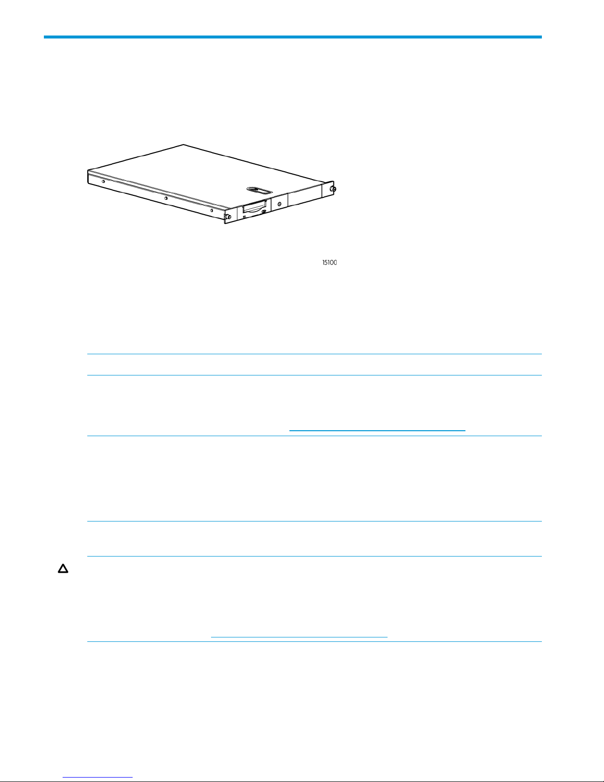
The HP StoreEver 1U Rack-mount Enclosure is a rack-mountable storage system capable of holding
up to two half-height 5.25 inch tape or RDX disk drives. It is compatible with most standard 19
inch racks.
Figure 1 1U Rack-mount Enclosure
Standard Features
Standard features of the 1U rack-mount enclosure:
• Supports one or two 5.25 inch half-height tape or RDX disk drives
• Installation in standard 19 inch racks with round, square, or threaded holes
NOTE: Daisy-chaining of two or more SCSI version 1U rack-mount enclosures is not supported.
Supported Controllers and HBAs
For up-to-date SCSI and SAS HBA compatibility information, review the compatibility matrix on
the Enterprise Backup Solutions website at: http://www.hp.com/storage/SPOCK.
NOTE: SCSI drives: The SCSI bus type determines the speed at which data can be transferred
between devices on the bus and the maximum length of cable that can be used. LTO–3 and LTO–4
tape drives support a burst transfer rate of 320 MB/sec. LTO–2 tape drives support a burst transfer
rate of 160 MB/sec. To benefit from this level of performance, it is important to ensure that the
drives are connected to a SCSI bus of a similar or higher specification. LTO–3 and LTO–4 SCSI
drives should be on their own SCSI bus.
SAS Cabling Recommendations
CAUTION: High quality external SAS cables rated at the transfer rate of the drive are required.
Always verify that the external SAS cable being used is rated for the data transfer speed of the
interface of your component. SAS cables described as "equalized" may not support 6 Gb/s data
rates and should not be used with LTO-5 or LTO-6 tape drives unless these cables are verified for
6 Gb/s data rates. For optimum performance, only use HP cables of the length specified as qualified
for your products. Refer to http://www.hp.com/storage/SPOCK for recommended cables.
The SAS interface board has two external ports illustrated below. The supplied internal SAS cable
supports connection of two devices. Several cabling configurations are possible, but the following
cabling configuration is recommended to provide the most consistent layout between devices and
external connectors.
Looking at the rack from the rear, the right-most external port is Port 1 and the left-most external
port is Port 2.
4 Introduction
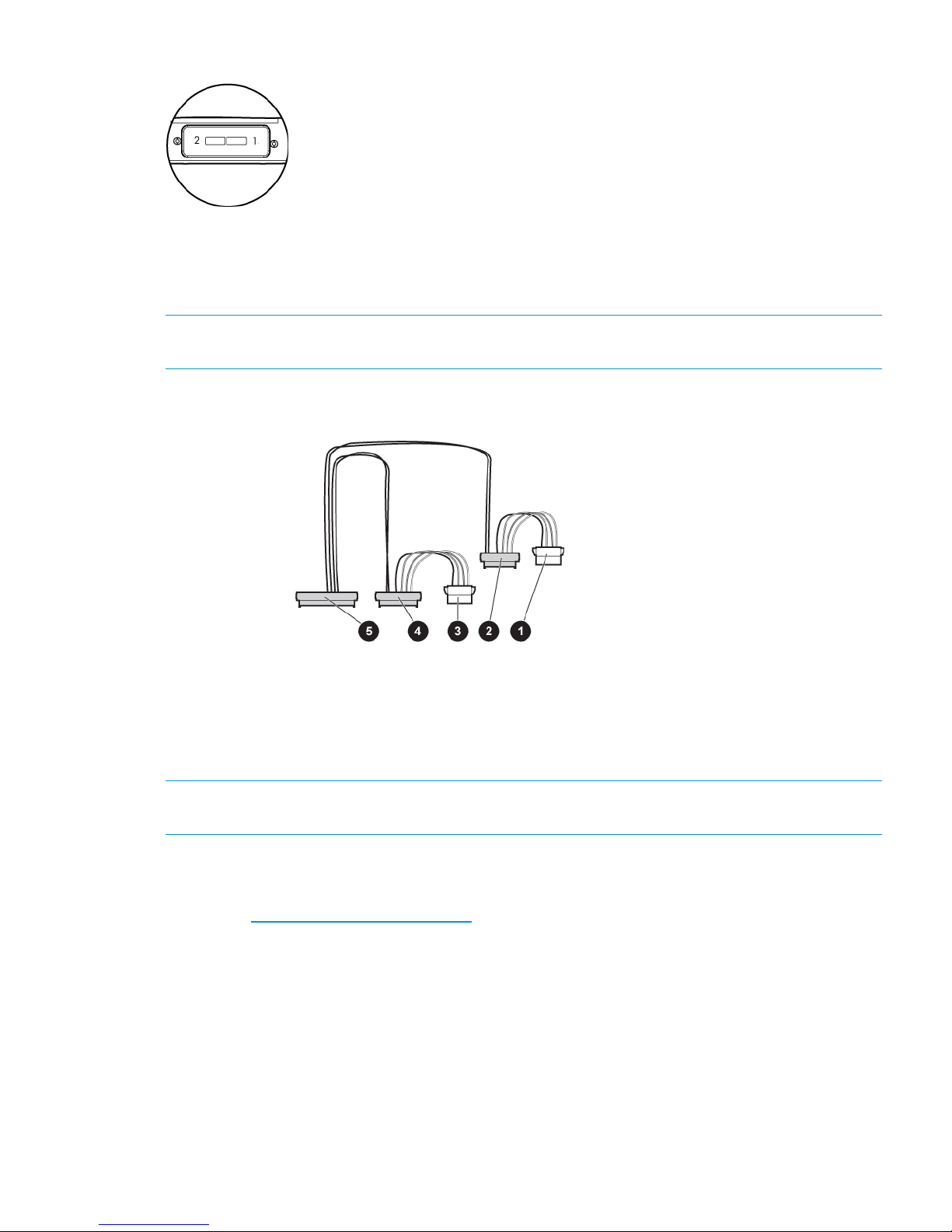
Figure 2 External SAS ports on the 1U rack-mount enclosure
When two SAS devices are installed, the right–most connector of the internal cable is connected
to the device on the right and the left-most connector of the internal cable is connected to the device
on the left. This routes the right-hand device to external port 1 and the left-hand device to external
port 2.
NOTE: The interface board has text, “Port 1–0” and “Port 2–0”, on the PCI board near the
internal SAS connector, which also helps identify the routing to the external ports.
Figure 3 Enclosure internal SAS cable
4. SAS connector routes device to external port 11. and 3. Power connectors (used only with LTO-5, LTO-6,
and DAT; do not use with other LTO drives)
5. SAS connector to PC board within the enclosure2. SAS connector routes device to external port 2
NOTE: Power for all DDS, LTO-5, and LTO–6 tape drives is supplied through the SAS cable. For
all earlier models of LTO tape drive, plug the power cable directly into the drive.
Hardware Options
For a list of currently supported hardware options, such as tape drives and media, visit the HP
website at: http://www.hp.com/go/tape.
Hardware Options 5
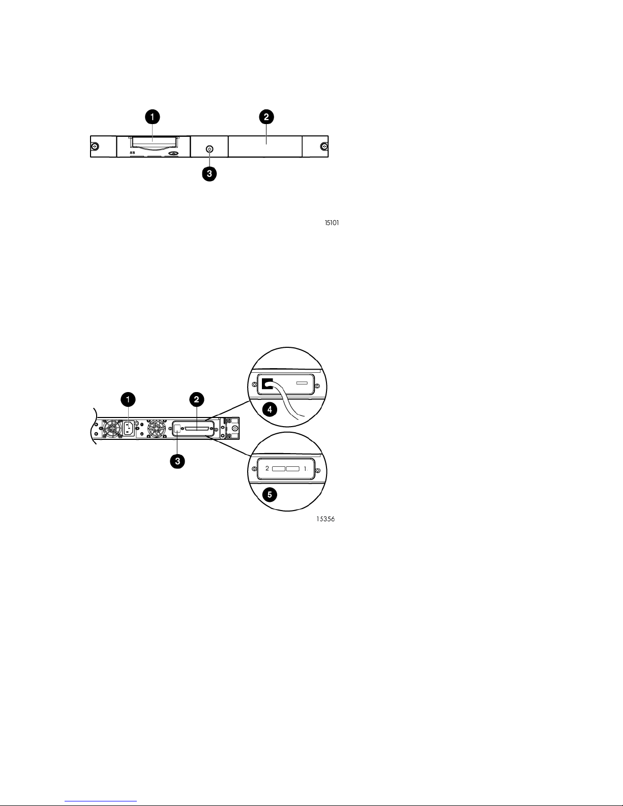
1U Rack-mount Enclosure Components
Front Panel Components
Figure 4 1U rack-mount enclosure front panel components
1. Drive bay
2. Expansion drive bay
3. Power switch/LED
Rear Panel Components
Figure 5 1U rack-mount enclosure rear panel components
2. SCSI Connector (SCSI models)1. AC Power Connector
4. USB Connector (USB models)3. SCSI ID Switch (SCSI mode Only)
5. SAS Connector (SAS models)
6 Introduction
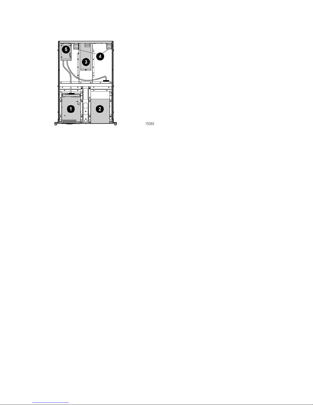
Internal Components (SAS version shown)
Figure 6 1U rack-mount enclosure internal components (SAS version)
2. Drive blank1. Drive
4. Fan assemblies (2)3. Power supply
5. SAS Repeater Board (SAS Models only)
1U Rack-mount Enclosure Components 7

2 Drive Installation
Tools Required
A 3/16” (5mm) flat-blade screwdriver or T-15 Torx driver may be required to install a drive in the
1U rack-mount enclosure.
Drive Blank Removal and Installation
CAUTION: To avoid damaging the equipment due to electrostatic discharge, be sure to review
and practice the procedures in Electrostatic discharge before handling the drives.
To install a tape or disk drive:
1. Remove the top access panel as shown.
Figure 7 Removing the access panel
2. Remove the drive blank:
a. Pull the spring-loaded button on the right mounting rail up.
b. Slide the assembly forward and then lift up.
Figure 8 Removing the drive blank
3. Remove the mounting brackets from the drive blank.
8 Drive Installation
 Loading...