

HP StoreAll 8200, StoreAll 8800, StoreAll 9300, StoreAll 9320, StoreAll 9730 Storage Installation Guide
Page 1

HP StoreAll Storage Installation Guide
Abstract
This document describes how to install the HP StoreAll OS Software and provides an overview on installing and cabling related
devices, and configuring applicable HP StoreAll Storage systems. It is intended for HP Services personnel who install and
configure HP StoreAll 8xxx and 9xxx Storage systems at customer sites. Document users should be well-versed in installing the
HP StoreAll OS Software, using Linux operating systems, and using StoreAll commands. For upgrade information, see the HP
StoreAll OS Upgrade Guide for the applicable StoreAll OS Software version. For the latest HP StoreAll Storage system guides,
see http://www.hp.com/support/StoreAllManuals.
HP Part Number: TA768-96313
Published: May 2014
Edition: 13
Page 2

© Copyright 2009, 2014 Hewlett-Packard Development Company, L.P.
Confidential computer software. Valid license from HP required for possession, use or copying. Consistent with FAR 12.211 and 12.212, Commercial
Computer Software, Computer Software Documentation, and Technical Data for Commercial Items are licensed to the U.S. Government under
vendor's standard commercial license.
The information contained herein is subject to change without notice. The only warranties for HP products and services are set forth in the express
warranty statements accompanying such products and services. Nothing herein should be construed as constituting an additional warranty. HP shall
not be liable for technical or editorial errors or omissions contained herein.
Acknowledgements
Microsoft, Windows, Windows XP, and Windows NT are U.S. registered trademarks of Microsoft Corporation.
UNIX® is a registered trademark of The Open Group.
Revision History
DescriptionSoftware
Version
DateEdition
Initial release of HP StorageWorks 9000 File Serving Software5.3.1November 20091
Updated license and quotas information5.3.2 or laterDecember 20092
Major revision of installation and configuration information5.4 or laterApril 20103
Added 9720 on-site commissioning information; revise system restore information;
removed installation blueprints chapter
5.4 or laterMay 20104
Updated for the 9000 Software 5.5 release5.5 or laterDecember 20105
Added network best practices for 9720 systems, updated the network best practices
for 9300 and 8800 systems, and updated the configuration procedure for the
management console and file serving nodes
5.5 or laterMarch 20116
Updated network best practices, added installation and configuration information for
9720 systems
5.6 or laterJune 20117
Updated installation and configuration information, replaced Support Ticket with Ibrix
Collect, added information about ibrixinit
6.0 or laterSeptember 20118
Added new installation procedures and wizards for 9300, 9320, and 9730 systems6.1 or laterJune 20129
Added VLAN tagging information, updated installation information.6.2 or laterDecember 201210
Changed name of product from IBRIX to StoreAll. Updated installation procedures
and screen captures for 9730.
6.3 or laterMarch 201311
Added the HP StoreAll 8200 and 8800 Storage systems. Provided steps on how to
create a bootable USB flash drive.
6.5 or laterFebruary 201412
Updated/added cabling and networking diagrams for Storage 8800 systems. Updated
with a general edit.
6.5.1 or laterMay 201413
Page 3

Contents
1 About the HP StoreAll Storage System...........................................................7
Supported platforms..................................................................................................................7
Factory default and current HP StoreAll OS Software version information..........................................7
Limitations and restrictions..........................................................................................................7
2 Setting up and installing HP StoreAll hardware...............................................9
Understanding platform configurations........................................................................................9
HP StoreAll 8200 Gateway Storage system configurations.........................................................9
HP StoreAll 8800 Storage system configurations....................................................................12
HP StoreAll 9300 Gateway Storage system configuration........................................................15
HP StoreAll 9320 Storage system configurations.....................................................................16
HP StoreAll 9730 Storage system configurations.....................................................................19
Installing HP StoreAll Storage system hardware components into a rack.........................................21
Selecting an HP cabinet and determining HP StoreAll component locations within the rack..........21
Before you install HP StoreAll rack components......................................................................21
Disk drive layouts....................................................................................................................22
Understanding network connections..........................................................................................23
HP StoreAll 8xxx and 93xx hardware network layout information.............................................23
HP StoreAll 8xxx and 93xx Storage system prerequisites.........................................................25
HP StoreAll 9730 network layouts........................................................................................26
IP address requirements for flat (unified) networks...................................................................27
Cabling HP StoreAll Storage system components.........................................................................28
Cabling the HP StoreAll 8200 Gateway system......................................................................28
Cabling the HP StoreAll 8800 Storage system.......................................................................33
Cabling the HP StoreAll 9320 Storage system........................................................................41
Cabling the HP StoreAll 9730 Storage system........................................................................47
Cabling verification (8800 and 9730 only)................................................................................48
Power on...............................................................................................................................49
3 Installing the HP StoreAll OS Software and configuring the HP StoreAll Storage
system........................................................................................................50
Creating a bootable device and installing the HP StoreAll OS Software.........................................51
Creating a bootable DVD and installing the HP StoreAll OS Software.......................................52
Creating a bootable USB flash drive and installing the HP StoreAll OS Software........................53
Creating a bootable USB flash drive on Linux....................................................................53
Creating a bootable USB flash drive on Windows.............................................................53
Configuring initial and subsequent nodes on HP StoreAll 8xxx and 93xx Storage systems................55
Before you begin configuring HP StoreAll 8xxx and 93xx Storage systems.................................55
Configuring HP StoreAll 8xxx and 93xx nodes with iLO.....................................................55
Verifying LUNs and component firmware...............................................................................57
Configuring nodes and a cluster on the HP StoreAll 8xxx and 93xx Storage system....................58
Completing the HP StoreAll 8xxx and 93xx server installation by configuring servers and a cluster
in ASCII mode...................................................................................................................72
Configuring the HP StoreAll 9730 Storage systems......................................................................74
Before you begin configuring HP StoreAll 9730 Storage systems..............................................74
HP StoreAll 9730 hardware configuration information........................................................74
Configuring HP StoreAll 9730 nodes with iLO...................................................................75
Verifying LUNs and component firmware..........................................................................76
Configuring OA1 IP addresses for the Onboard Administrator.................................................77
Configuring the chassis on the HP StoreAll 9730 Storage system..............................................79
Creating a cluster using ASCII mode on blade 1 on the HP StoreAll 9730 Storage system...........93
Installing additional HP StoreAll 9730 Storage system blades..................................................95
Contents 3
Page 4

Troubleshooting HP StoreAll 9730 Storage system installation issues.......................................101
4 Configuring clusters remotely with the Getting Started Wizard......................105
Getting Started Wizard prerequisites.......................................................................................105
Accessing the Getting Started Wizard.....................................................................................105
Step 1 - Setting up Cluster Settings..........................................................................................107
Providing cluster information..............................................................................................107
Completing the Update License screen................................................................................108
Step 2 - Designating IP addresses for DNS/NTP servers.............................................................109
Step 3 - Reviewing servers listed on the File Servers screen and designating which servers to be
included in the cluster............................................................................................................109
Configuring File Servers....................................................................................................110
Adding a server..............................................................................................................111
Step 4 - Creating a Default File System....................................................................................112
Step 5 - Reviewing the Summary.............................................................................................113
Troubleshooting the Getting Started Wizard.............................................................................114
Cluster Settings page........................................................................................................114
DNS/FTP screen..............................................................................................................115
File Servers screen............................................................................................................115
Create a Default File System screen....................................................................................124
5 Discovering and configuring HP StoreAll servers and their storage................127
Server and Storage Expansion Wizard prerequisites.................................................................127
Accessing and using the HP StoreAll Server & Storage Expansion Wizard...................................127
Logging in to the HP Management Console.........................................................................127
Accessing the File Servers screen.......................................................................................128
Step 1 - Managing the File Servers screen................................................................................129
Adding file servers...........................................................................................................130
Removing file servers........................................................................................................131
Step 2 - Configuring a File Server...........................................................................................131
Configuring bonds...........................................................................................................131
Selecting bonds from the Network Management screen........................................................132
Viewing and updating node firmware from the Confirmation screen........................................132
Step 3 - Viewing Unused Storage............................................................................................133
Step 4 - Creating/Extending a File System...............................................................................134
Step 5 - Selecting File System Storage......................................................................................135
Creating new storage.......................................................................................................135
Step 6 - Enabling/Disabling Configure Options........................................................................136
Step 7 - Configuring WORM/Retention...................................................................................136
Configuring Express Query...............................................................................................138
Step 8 - Configuring Auditing.................................................................................................139
Step 9 - Configuring Default File Shares...................................................................................141
Step 10 - Reviewing the Summary...........................................................................................142
6 Configuring virtual IP addresses................................................................144
Network and virtual interface (VIF) guidelines...........................................................................144
Creating a bonded VIF..........................................................................................................145
Configuring backup servers....................................................................................................145
Configuring NIC failover.......................................................................................................145
Configuring automated failover..............................................................................................146
Example configuration...........................................................................................................146
Specifying VIFs in the client configuration.................................................................................146
Configuring VLAN tagging....................................................................................................147
Configuring link state monitoring for iSCSI network interfaces.....................................................148
7 Post-installation tasks...............................................................................149
Updating license keys...........................................................................................................149
4 Contents
Page 5

Resetting the ibrix_fm_tune parameter.....................................................................................149
Configuring and enabling high availability..............................................................................149
HP StoreAll 9730 Storage systems......................................................................................149
HP StoreAll 8xxx and 93xx Storage systems........................................................................149
Using the HP StoreAll Management Console............................................................................149
Changing the default password for the default users.............................................................150
HP StoreAll OS Software manpages........................................................................................150
Configuring data collection with Ibrix Collect............................................................................150
Configuring HP Insight Remote Support...................................................................................150
Creating file systems.............................................................................................................150
Configuring NFS exports.......................................................................................................150
Configuring SMB shares........................................................................................................151
Configuring other HP StoreAll OS Software features..................................................................151
Configuring block snapshots with HP StoreAll file systems and HP 3PAR Storage......................151
Using ibrixinit.......................................................................................................................151
Setting up InfiniBand couplets................................................................................................153
Downloading and installing the InfiniBand software..............................................................154
Installing the driver for InfiniBand.......................................................................................154
Troubleshooting the InfiniBand network...............................................................................155
Enabling InfiniBand client access.......................................................................................156
Setting up Voltaire InfiniBand ...........................................................................................156
8 Installing and configuring HP StoreAll clients for Linux and Windows
(optional).................................................................................................158
Installing and configuring the HP StoreAll Linux client................................................................158
Prerequisites for installing the HP StoreAll Linux client............................................................158
Installing the HP StoreAll Linux client software......................................................................159
Registering HP StoreAll Linux clients....................................................................................159
Registering multicluster clients............................................................................................159
Preferring a network interface for an HP StoreAll Linux client..................................................160
Preferring a network interface for a hostgroup......................................................................160
Removing an HP StoreAll client from the cluster....................................................................160
Installing and configuring the HP StoreAll Windows client..........................................................160
System requirements.........................................................................................................161
Installing the HP StoreAll Windows client............................................................................161
Configuring the HP StoreAll Windows client........................................................................162
Configuring Windows Services for UNIX (SFU)....................................................................162
Configuring automatic user mapping..................................................................................162
Configuring static user mapping........................................................................................163
Configuring groups and users on the Active Directory server.............................................163
Configuring Active Directory settings on the management console.....................................164
Registering HP StoreAll Windows clients and starting services................................................164
Importing UIDs/GIDs to the Active Directory server..............................................................166
Using the HP StoreAll Windows client GUI..........................................................................166
Preferring a user network interface for a Windows client.......................................................167
Enabling file system access...............................................................................................167
Managing Access Control Lists..........................................................................................167
Uninstalling HP StoreAll clients on Linux and Windows..............................................................170
Uninstalling HP StoreAll Linux clients...................................................................................170
Uninstalling HP StoreAll Windows clients............................................................................170
9 Support and other resources....................................................................172
Contacting HP......................................................................................................................172
Related information...............................................................................................................172
HP websites.........................................................................................................................172
Contents 5
Page 6

10 Documentation feedback.......................................................................173
A HP StoreAll Storage system physical specifications and power requirements...174
HP StoreAll 8200 physical specifications and power requirements...............................................174
HP StoreAll 8800 physical specifications and power requirements...............................................174
HP StoreAll 9300 Storage system physical specifications and power requirements.........................175
HP StoreAll 9320 Storage system physical specifications and power requirements.........................176
HP StoreAll 9730 physical specifications and power requirements...............................................176
B Installation checklists...............................................................................178
Customer contact details........................................................................................................179
Site readiness checklists.........................................................................................................180
New and existing product information.....................................................................................184
Required network and installation information..........................................................................185
C Creating an IMG file from an ISO in Windows..........................................204
D Expanding an existing HP StoreAll Storage system using the Setup Wizard....207
Expanding an HP StoreAll Storage 8800/9320 10 GbE cluster with an HP StoreAll 9730 module...207
Prerequisites....................................................................................................................207
Installing the initial expansion blade...................................................................................207
Installing the second expansion blade................................................................................220
Using the new storage......................................................................................................227
Verifying vendor storage..............................................................................................228
Importing new physical volumes into the HP StoreAll database .........................................228
Expanding an existing file system..................................................................................229
Expanding an 8800/9320 cluster with an 8800/9320 starter kit...............................................230
Installing the expansion server...........................................................................................230
Completing the installation from the Getting Started Wizard..................................................236
Completing the installation with the ASCII text wizard...........................................................238
E Installing an HP StoreAll Storage 9730 system Performance Module with the
Setup Wizard...........................................................................................240
Performance Module installation prerequisites...........................................................................240
Installing expansion blades....................................................................................................240
Using the new storage...........................................................................................................248
Glossary..................................................................................................251
6 Contents
Page 7

1 About the HP StoreAll Storage System
The HP StoreAll Storage system is a complete software and hardware solution that enables users
to manage unstructured data storage requirements. The HP StoreAll Storage system uses compatible
nodes (servers) and storage devices, and data requirements are managed through a simple-to-use
graphical user interface application. With HP StoreAll Storage, users can scale data center
requirements to billions of files, 16 petabytes, and 1,024 nodes in a single namespace with
centralized management.
Supported platforms
Supported platforms discussed in this guide include:
• HP StoreAll 8200 Gateway Storage system
• HP StoreAll 8800 Storage system
• HP StoreAll 9300 Gateway Storage system
• HP StoreAll 9320 Storage system
• HP StoreAll 9730 Storage system
Factory default and current HP StoreAll OS Software version information
The current HP StoreAll OS Software version is v6.5.
Pre-installed HP StoreAll OS Software versions for all HP-supported HP StoreAll Storage systems
are listed in Table 1 (page 7).
Table 1 Factory default versions for HP StoreAll storage systems
Factory default version of the HP StoreAll OS Software
installed on newly shipped modelsModel
v.6.5 or laterHP StoreAll 8200 Gateway Storage system
v6.5 or laterHP StoreAll 8800 Storage system
v6.3.1 or laterHP StoreAll 9300 Gateway Storage system
v6.3.1 or laterHP StoreAll 9320 Storage system
v6.3.1 or laterHP StoreAll 9730 Storage system
New installations are no longer available.IBRIX X9720 storage system
Limitations and restrictions
Observe the following limitations and restrictions associated with the installation and configuration
of HP StoreAll Storage systems:
• HP StoreAll nodes (servers), based on the HP ProLiant DL380 Gen6 blade, are not compatible
with the current HP StoreAll OS Software version of HP StoreAll OS Software. HP Storage
systems using this specific type of node must be upgraded to an HP ProLiant DL380 Gen7 or
later device. See “Factory default and current HP StoreAll OS Software version information”
(page 7) for the current HP StoreAll OS Software version of the HP StoreAll OS Software.
Only Gen7 and Gen8 hardware platforms, listed in Table 2 (page 8), are supported with
the current HP StoreAll OS Software version.
Supported platforms 7
Page 8

Table 2 Supported Gen7 and Gen8 platforms
GenerationDescriptionSKU
Gen7HP X9300 1 GbE Network Storage GatewayAW539C
Gen7HP X9300 IBRIX 1GbE GatewayAW539D
Gen7HP X9300 10 GbE/InifiBand (IB) Network Storage GatewayAW540C
Gen7HP X9300 IBRIX 10 GbE/IB Storage GatewayAW540D
Gen7HP StorageWorks X9300 Management ServerAW547C
Gen 7HP X9700 Blade ServerAW550C
Gen7HP X9320 10 GbE Performance BlockQP330A
Gen7HP X9320 1 GbE 2xDL Performance BlockQP330B
Gen7HP X9320 10 GbE Performance BlockQP331A
Gen7HP X9320 10 GbE 2xDL Performance BlockQP331B
Gen7HP X9320 IB Performance BlockQP332A
Gen7HP X9320 IB 2xDL Performance BlockQP332B
Gen7HP X9730 140 TB ML Stor 2xBL Performance ModuleQZ730A
Gen7HP X9730 210 TB ML Stor 2xBL Performance ModuleQZ731A
Gen7HP X9730 140 TB 6G ML Str 2xBL Performance ModuleQZ732A
Gen7HP X9730 210 TB 6G ML Str 2xBL Prf ModuleQZ733A
Gen8HP StoreAll 8200 Gateway Storage NodeH6Z59A
Gen8HP StoreAll 8800 Storage NodeH6Z60A
• The physical and structural capacity, including the electrical power capacity, of the data center
or site at which HP StoreAll Storage system hardware is to reside must be able to accommodate
the power, weight, and size requirements of the HP StoreAll Storage system to ensure the
uneventful delivery and physical installation of the system. See “HP StoreAll Storage system
physical specifications and power requirements” (page 174) for additional information on HP
StoreAll Storage systems weight and size constraints. You may also download the HP StoreAll
sizing tool at http://h30144.www3.hp.com/SWDSizerWeb/ to determine hardware capacity
requirements.
• If your HP StoreAll Storage system installation includes the use of the Mode 4 networking
option (LACP spanning multiple physical network ports) and if you plan to use the Getting
Started Wizard, you must manually configure the IP addressing of all the nodes and blades
before using the Getting Started Wizard. See “Configuring clusters remotely with the Getting
Started Wizard” (page 105) for additional information on the Getting Started Wizard.
• The HP StoreAll 8200 Gateway Storage systems can be seamlessly clustered with other HP
StoreAll Storage systems, such as HP StoreAll 8800, 9300, 9320, and 9730 Storage systems.
For a complete listing of supported storage systems, see the applicable storage system
QuickSpecs, or see related HP StoreAll OS Software release notes.
• For the HP StoreAll 8800 Storage system, multiple couplets and different HP StoreAll models,
such as the HP StoreAll 8200, 9300, 9320, 9730 Storage systems, can be seamlessly
combined and connected. For a complete listing of supported storage systems, see applicable
storage system QuickSpecs, or see related HP StoreAll OS Software release notes.
8 About the HP StoreAll Storage System
Page 9

2 Setting up and installing HP StoreAll hardware
This chapter describes the hardware components used in HP StoreAll Storage systems, and provides
cabling diagrams and networking information.
Understanding platform configurations
HP StoreAll 8200 Gateway Storage system configurations
The HP StoreAll 8200 supports the following configurations:
• 1 GbE network storage gateway
• 10 GbE network storage gateway
The system is comprised of HP StoreAll nodes, which are based on the ProLiant DL380p Gen8
server, and can be connected to select HP 3PAR StoreServ 7000- or 10000-series FC storage
systems.
NOTE: For specific hardware details for each configuration, see the HP StoreAll 8000 Storage
QuickSpecs, available at: http://h18004.www1.hp.com/products/quickspecs/14792_na/
14792_na.pdf
See the following cabling diagrams for possible configurations of the HP StoreAll 8200 Gateway
Storage system.
Figure 1 HP StoreAll 8200 Gateway system with an HP 3PAR StoreServ P7200 (front)
1. HP StoreAll node couplet (front)
2. HP 3PAR StoreServ P7200 FC storage (front)
Understanding platform configurations 9
Page 10
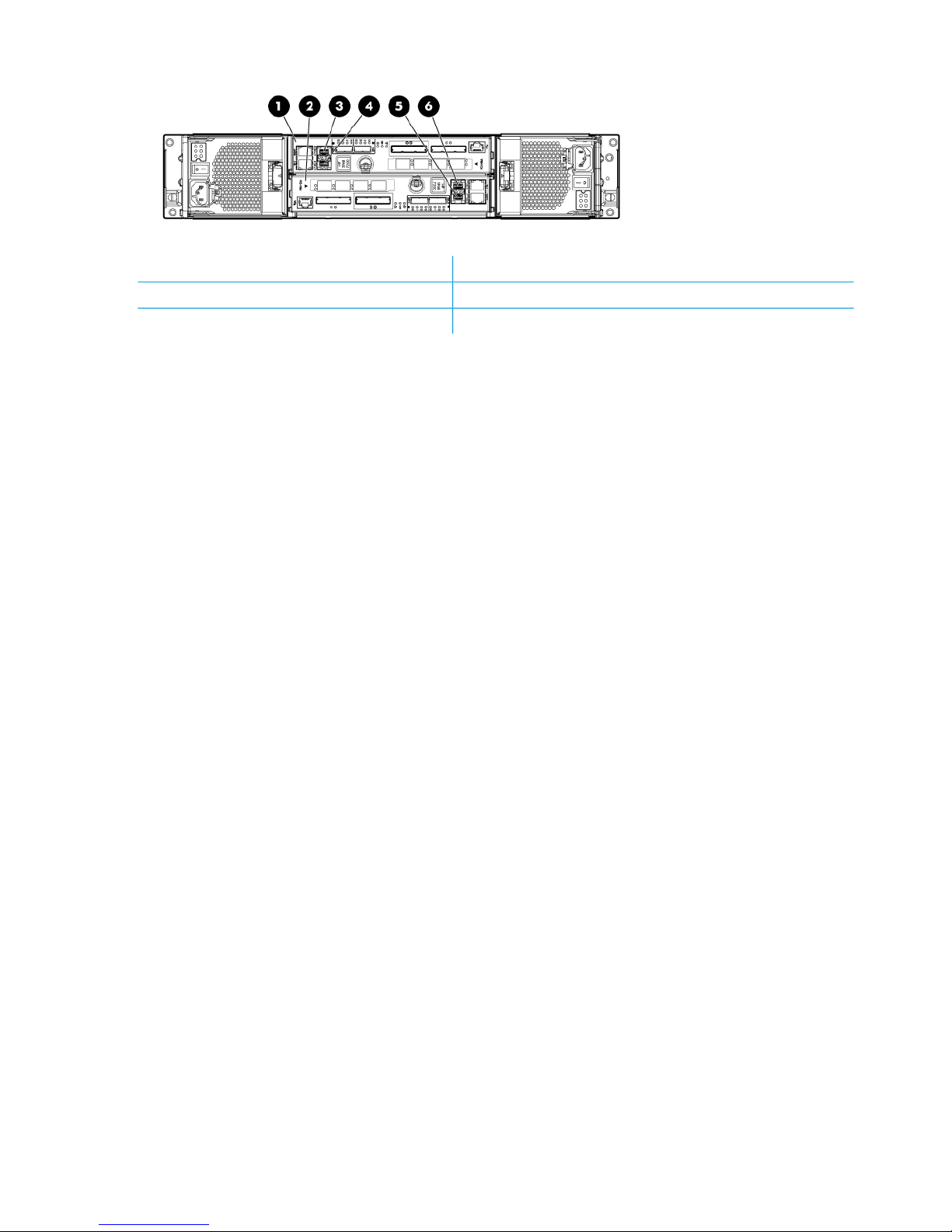
Figure 2 HP 3PAR StoreServ 7200 (rear)
4. Port FC-1 on Node 11. Node 1
5. Port FC-2 on Node 02. Node 0
6. Port FC-1 on Node 03. Port FC-2 on Node 1
10 Setting up and installing HP StoreAll hardware
Page 11

Figure 3 HP StoreAll 8200 Gateway system with 1 GbE network ports (rear)
6. Slot 6 — 1 GbE NICs (ports 1–4 from right to left)1. Slot 1 (blank)
7. iLO port2. Slot 2 — FC HBA (3PAR connection)
8. eth0 (port 1) — for management network3. Slot 3 — FC HBA (optional tape connection)
9. eth1 (port 2) — for management network4. Slot 4 (blank)
5. Slot 5 — 1 GbE NICs (ports 1–4 from right to left)
Understanding platform configurations 11
Page 12
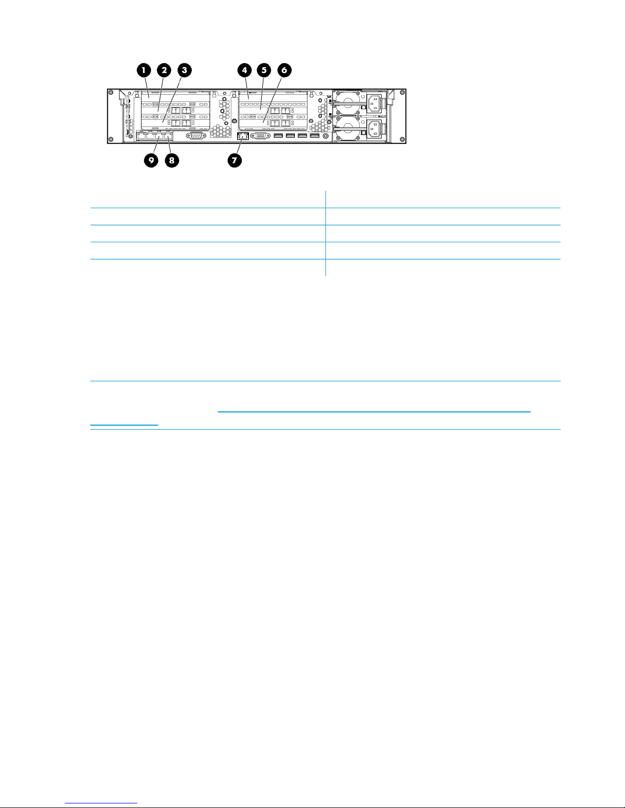
Figure 4 HP StoreAll 8200 Gateway system with 10 GbE network ports (rear)
6 Slot 6 — 10 GbE NICs (ports 1–2 from right to left)1. Slot 1 (blank)
7. iLO port2. Slot 2 — FC HBA (3PAR connection)
8. eth0 (port 1) — for management network3. Slot 3 — FC HBA (optional tape connection)
9 eth1 (port 2) — for management network4. Slot 4 (blank)
5. Slot 4 — 10 GbE NICs (ports 1–2 from right to left)
HP StoreAll 8800 Storage system configurations
The HP StoreAll 8800 supports the following configurations:
• HP StoreAll 8800 couplet configured with HP Enterprise (ENT) SAS capacity blocks
• HP StoreAll 8800 couplet configured with HP Midline (MDL) SAS capacity blocks
• HP StoreAll 8800 couplet configured with both HP ENT SAS and MDL SAS capacity blocks
NOTE: For specific hardware details for each configuration, see the HP StoreAll 8000 Storage
QuickSpecs, available at: http://h18004.www1.hp.com/products/quickspecs/14792_na/
14792_na.pdf.
See the following diagrams for possible configurations of the HP StoreAll 8000 Storage system,
12 Setting up and installing HP StoreAll hardware
Page 13
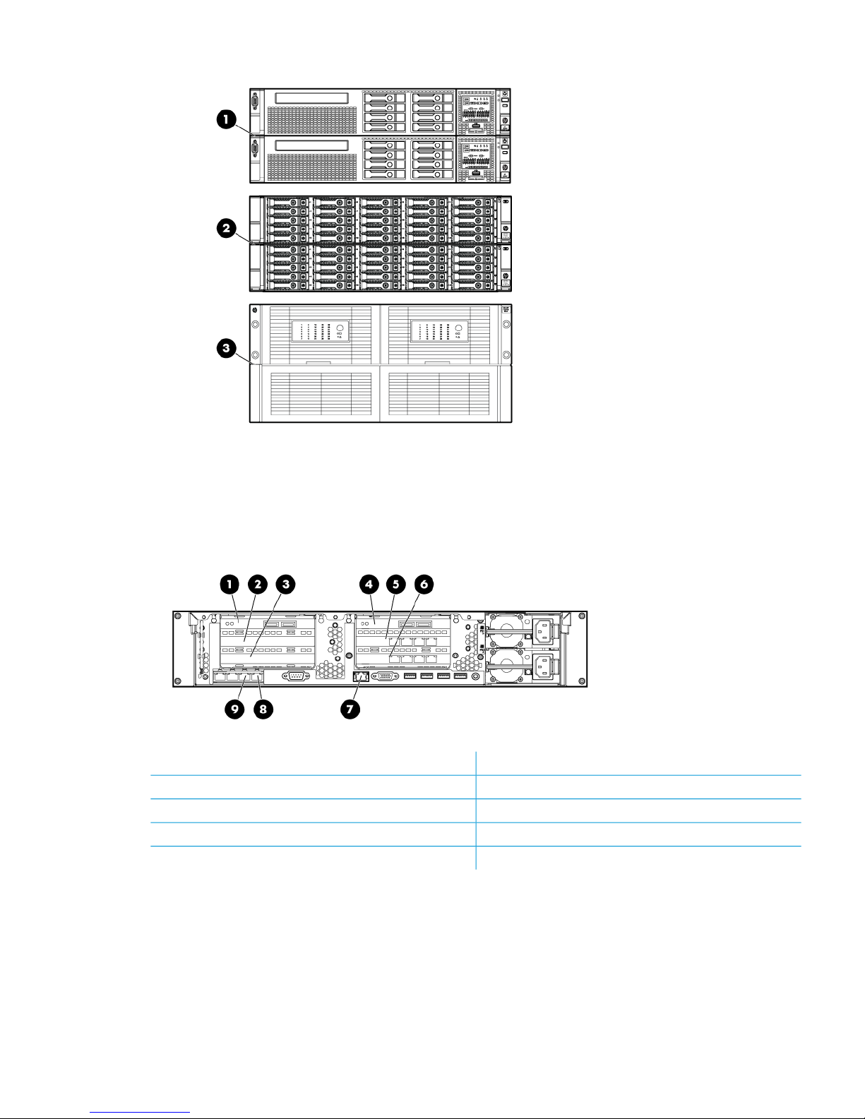
Figure 5 HP StoreAll 8800 Storage system with HP ENT SAS and MDL SAS capacity blocks (front)
1. HP StoreAll node couplet (front)
2. ENT SAS capacity block
3. MDL SAS capacity block
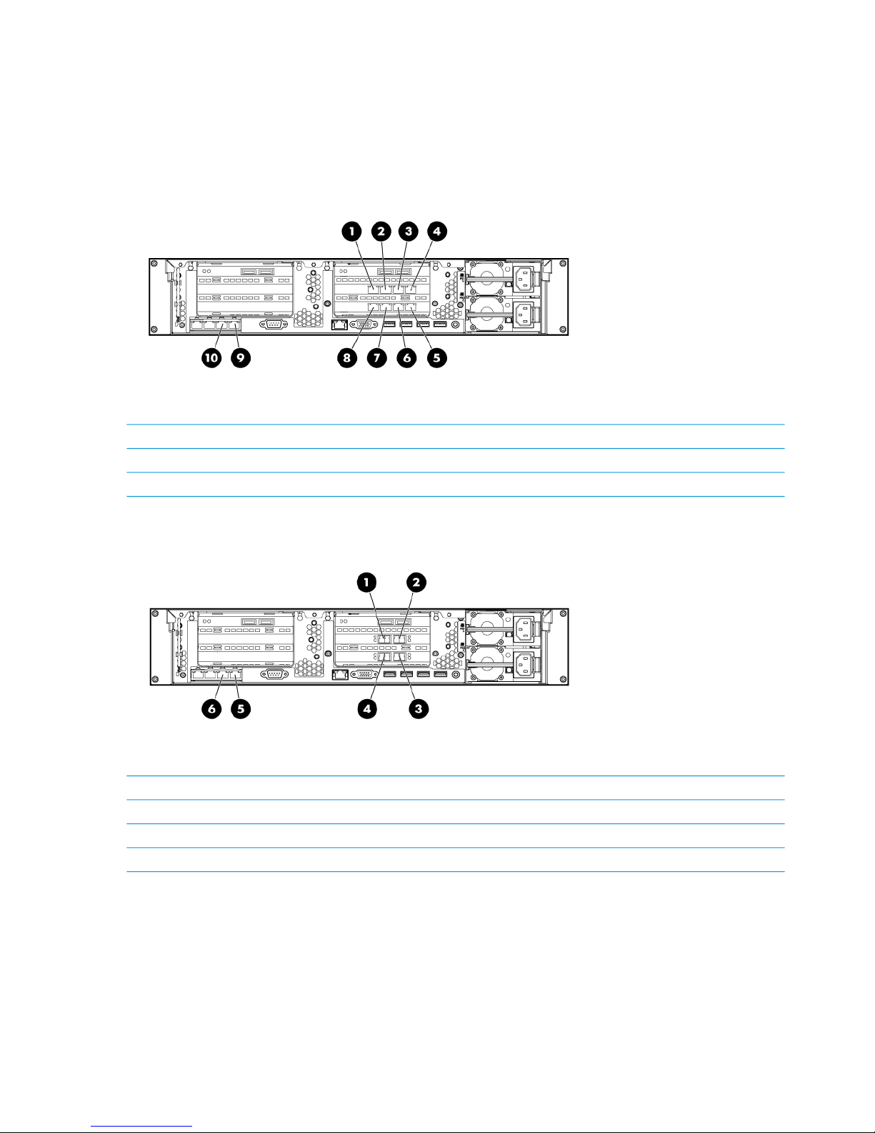
Figure 6 HP StoreAll 8800 Storage system with 1 GbE network ports (rear)
6. Slot 6 — 1 GbE NICs (ports 1–4 from right to left)1. Slot 1 — Controller 1 (port 1 on right, port 2 on left)
7. iLO port2. Slot 2 (blank)
8. eth0 (port 1) — for management network3. Slot 3 (blank)
9. eth1 (port 2) — for management network4. Slot 4 — Controller 2 (port 1 on right, port 2 on left)
5. Slot 5 — 1 GbE NICs (ports 1–4 from right to left)
Understanding platform configurations 13
Page 14
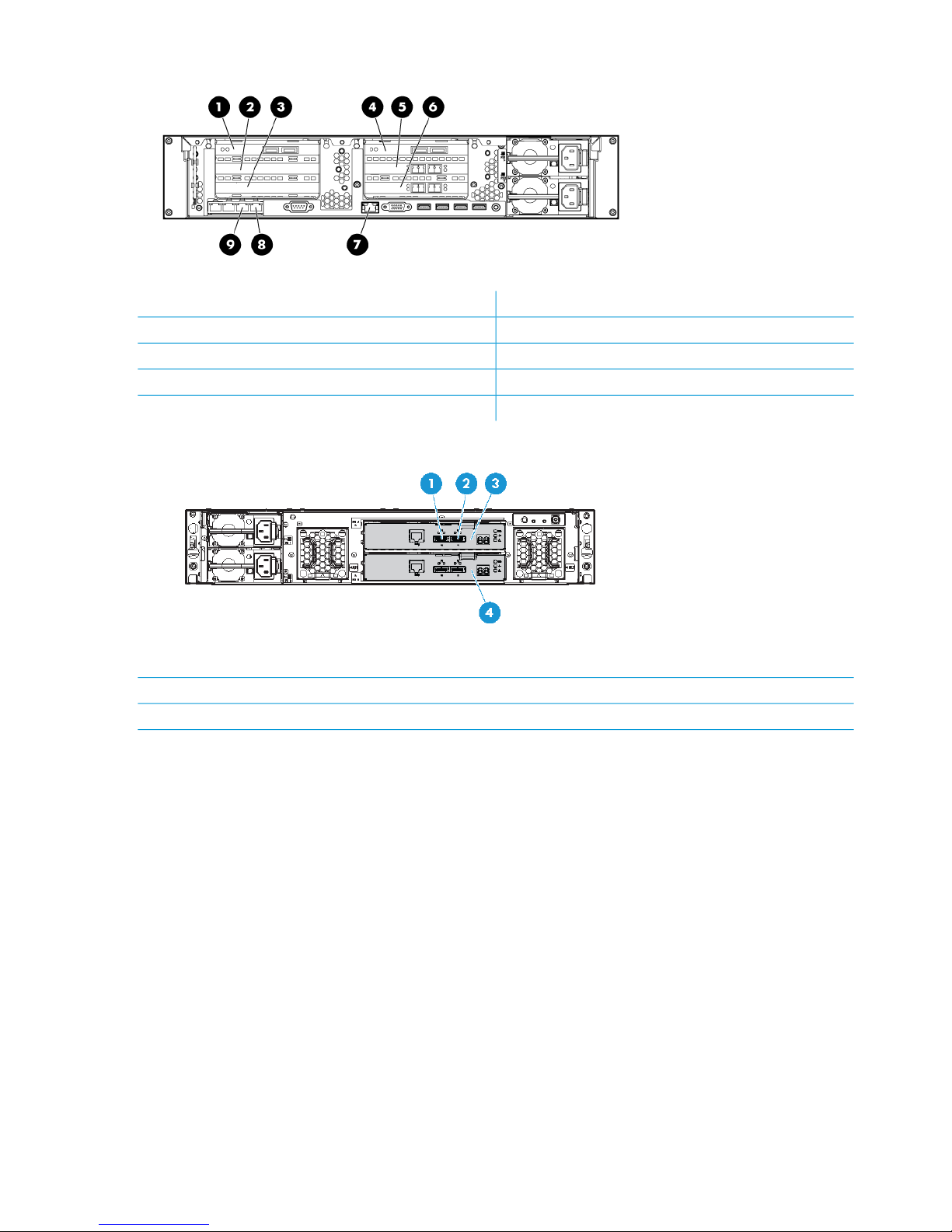
Figure 7 HP StoreAll 8800 Storage system with 10 GbE network ports (rear)
6. Slot 6 — 10 GbE NICs (ports 1–4 from right to left)1. Slot 1 — Controller 1 (port 1 on right, port 2 on left)
7. iLO port2. Slot 2 (blank)
8. eth0 (port 1) — for management network3. Slot 3 (blank)
9.eth1 (port 2) — for management network4. Slot 4 — Controller 2 (port 1 on right, port 2 on left)
5. Slot 5 — 10 GbE NICs (ports 1–4 from right to left)
Figure 8 ENT SAS capacity block (rear)
1. Port 1
2. Port 2
3. I/O module A
4. I/O module B
14 Setting up and installing HP StoreAll hardware
Page 15
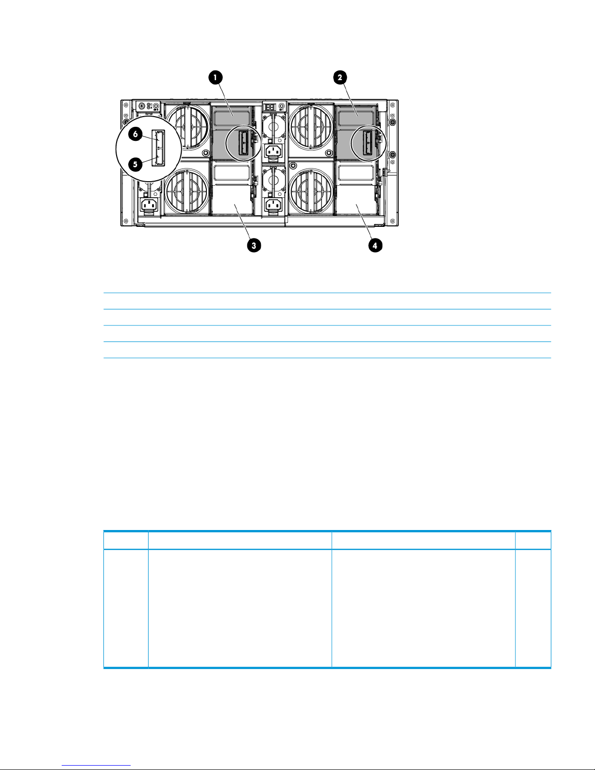
Figure 9 MDL SAS capacity block (rear)
1. Primary I/O module (drawer 2)
2. Primary I/O module (drawer 1)
3. Secondary I/O module (drawer 2)
4. Secondary I/O module (drawer 1)
5. SAS port 1 connector
6. SAS port 2 connector
HP StoreAll 9300 Gateway Storage system configuration
The HP StoreAll 9300 Gateway Storage system supports the following configurations, and these
configurations can be connected to select SANs/arrays, including HP 3PAR StoreServ, HP EVA,
and HP XP storage systems:
• 1 GbE network storage gateway
• 10 GbE/InfiniBand (IB) network storage gateway
Table 3 (page 15) provides additional information about HP StoreAll 9300 Gateway Storage
system features.
Table 3 HP StoreAll 9300 Storage system configuration components
QuantityDevice SpecificationsDeviceItem
At least
1 pair
Each server (node) includes:HP StoreAll node (based on the ProLiant DL380p
server Gen7)
1
• 1 GbE or 10 GbE/IB Gateway Storage
• Four or eight 1 GbE ports or up to two 10
GbE/IB ports
• One 2-, 4-, or dual-port HBA (FC or SAS) or
Network Adapter (iSCSI)
• (Model AW540D only)4- or dual-port server
adapter or IB PCIe G2 or PCIe dual port
HCA
Figure 10 (page 16) and Figure 11 (page 16) show an HP StoreAll 9300 Gateway Storage system.
Understanding platform configurations 15
Page 16
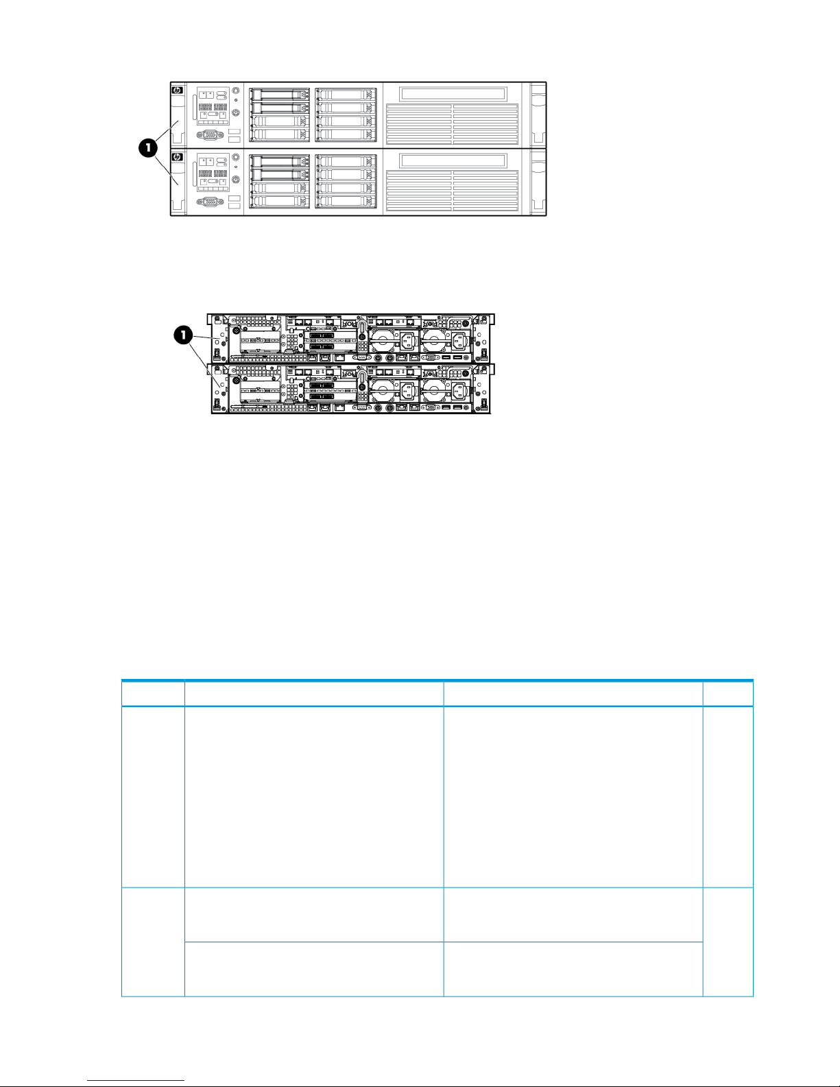
Figure 10 HP StoreAll 9300 Storage system (front)
1. HP StoreAll 9300 Storage Gateway node couplet
Figure 11 HP StoreAll 9300 Storage system - 10 GB (back)
1. HP StoreAll 9300 Storage Gateway node couplet
HP StoreAll 9320 Storage system configurations
The HP StoreAll 9320 Storage system configurations include:
• 1 GbE network storage system
• 10 GbE/IB network storage system
• InfiniBand (IB) port performance block
Table 4 (page 16) provides additional information about HP StoreAll 9320 Storage system
components.
Table 4 HP StoreAll 9320 Storage system configuration components
QuantityDevice SpecificationsDeviceItem
At least
1 pair
Each HP StoreAll node includes:HP StoreAll node (based on the ProLiant DL380p
Gen7 server)
1
• 24 GB (12 x 4 GB) (DDR3–1066) server
memory
• Four 1 GbE, four 10 GbE, or two IB ports
• Two 1 GbE NC382i Integrated Dual Port
PCIe ports
• Four 1 GbE LOM NICs
• HP Integrated Lights Out (iLO) 3
• HP SC08e SAS Host bus adapters (HBA)
At least
1,
24 300 or 900 GB SFF (10K Ent SAS) HDDs
each
SFF base capacity block: HP StoreAll SFF base
capacity block (based on the HP MSA P2000
G3 SAS dual controller SFF array system)
2
maximum
of 2
24 2 TB or 3 TB LFF (7.2K MDL SAS) HDDs
each
LFF base capacity block: HP StoreAll LFF base
capacity block (based on the HP MSA P2000
G3 SAS dual controller LFF array system)
16 Setting up and installing HP StoreAll hardware
Page 17
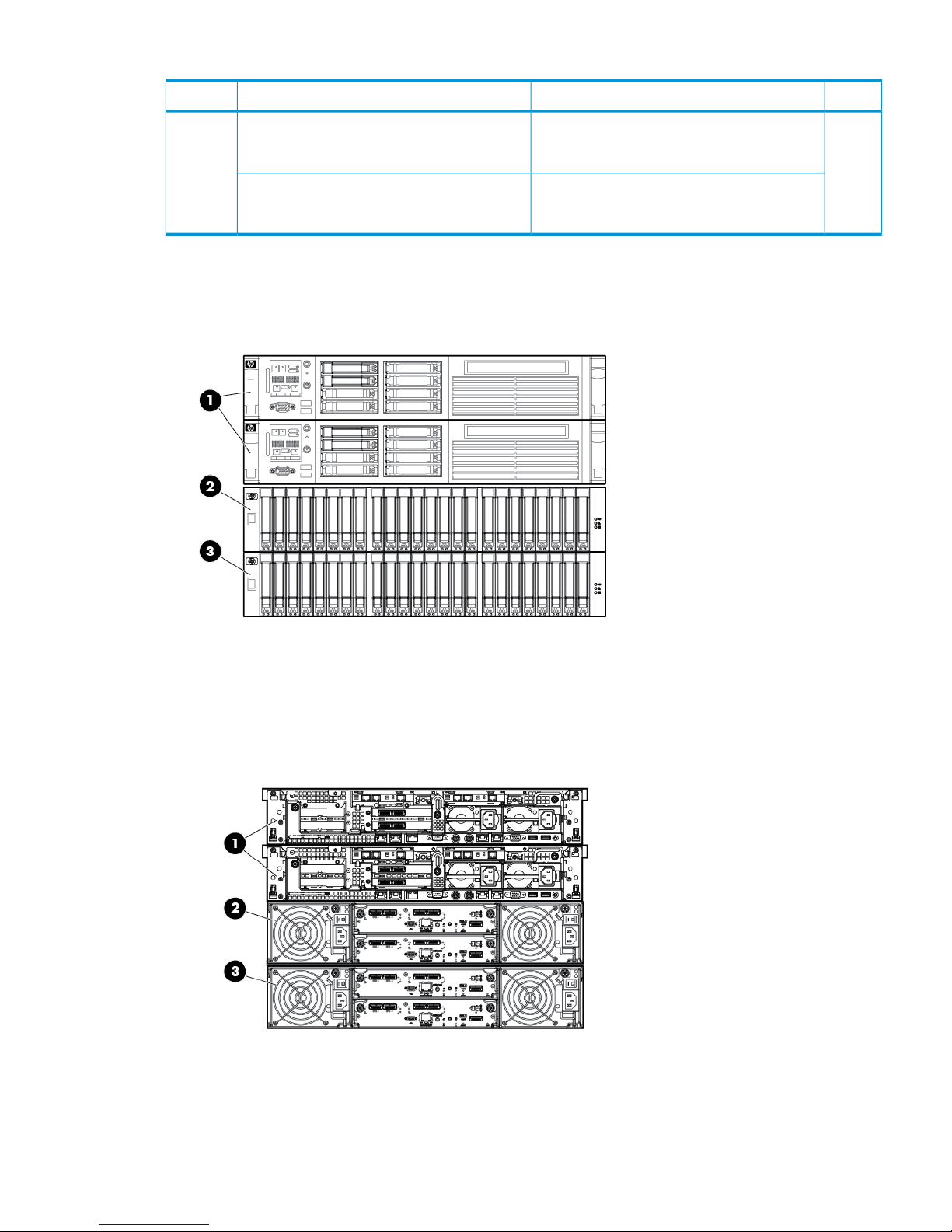
Table 4 HP StoreAll 9320 Storage system configuration components (continued)
QuantityDevice SpecificationsDeviceItem
Up to 6
LFF or
25 300 or 900 GB SFF (Ent SAS 10K) HDDs
each
SFF expansion kit: HP StoreAll expansion block
(based on the HP MSA P2000 G3 SAS dual
controller SFF array system)
3
up to
10 SFF
kits
24 2 TB or 3 TB LFF ((MDL SAS 7.2K) HDDsLFF expansion kit: HP StoreAll LFF capacity block
(based on the HP MSA P2000 G3 SAS dual
controller LFF array system)
Figure 12 (page 17), Figure 13 (page 17), Figure 14 (page 18), and Figure 15 (page 18) show
the HP StoreAll 9320 with SFF and LFF storage systems.
Figure 12 HP StoreAll 9320 Storage system-SFF (front)
1. HP StoreAll node pair
2. HP StoreAll SFF ENT SAS base capacity block (based on the MSA P2000 G3 storage system)
3. HP StoreAll SFF ENT SAS expansion block
Figure 13 HP StoreAll 9320 Storage system-SFF (back)
1. HP StoreAll node pair
2. HP StoreAll SFF ENT SAS base capacity block (based on the MSA P2000 G3 storage system)
3. HP StoreAll SFF ENT SAS expansion block
Understanding platform configurations 17
Page 18
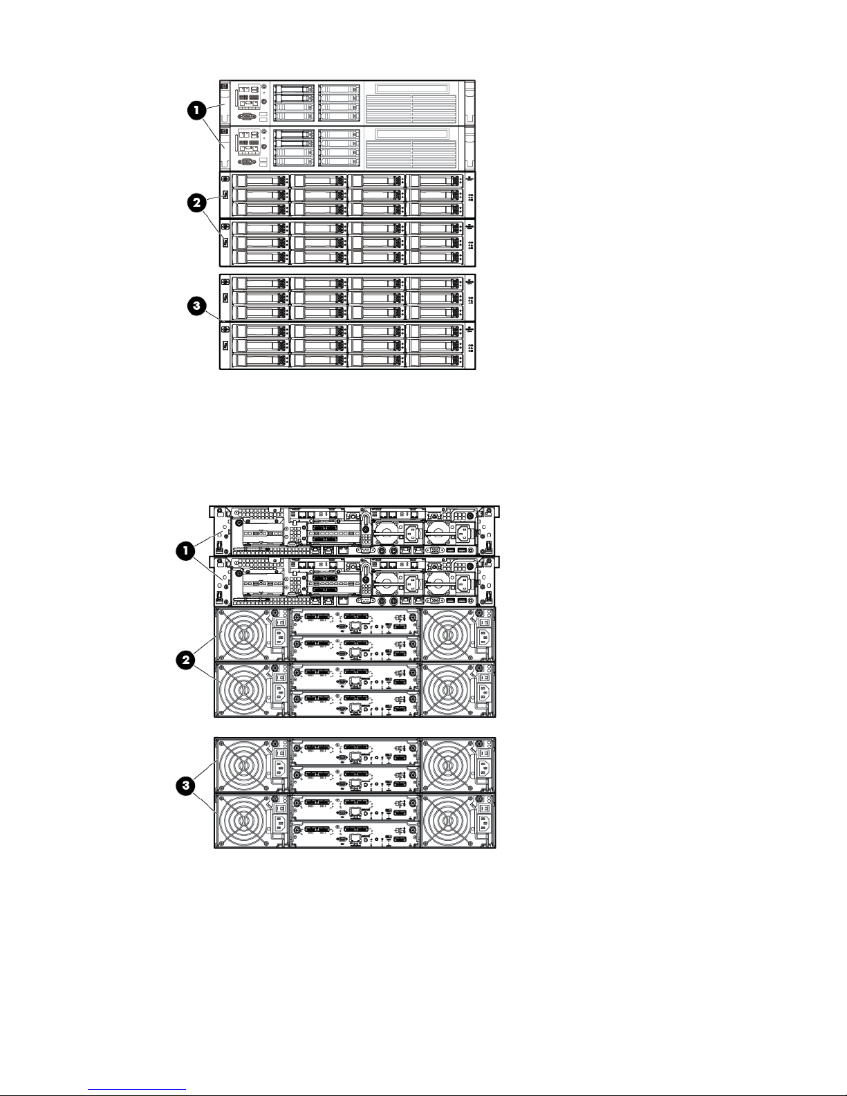
Figure 14 HP StoreAll 9320 Storage system-LFF 10 GbE (front)
1. HP StoreAll node pair
2. HP StoreAll LFF ENT SAS base capacity block
3. HP StoreAll LFF MDL SAS expansion block
Figure 15 HP StoreAll 9320 Storage system-LFF 10 GbE (back)
1. HP StoreAll node pair
2. HP StoreAll LFF ENT SAS base capacity block
3. HP StoreAll LFF MDL SAS expansion block
18 Setting up and installing HP StoreAll hardware
Page 19

HP StoreAll 9730 Storage system configurations
The HP StoreAll 9730 Storage system supports the following configurations:
• 140 Terabyte LFF storage couplet
• 210 Terabyte LFF storage couplet
The storage system includes:
• One HP 42U base rack with TFT/Monitor and Keyboard and support shelf
• One Performance Module (or Couplet) which includes two specifically configured BL460cGen7
servers each with one P1210m RAID controller installed and an MDS600 JBOD fully-loaded
with 2 TB or 3 TB HDDs.
• One HP c7000 chassis fully-loaded with power supplies and fans with 2 VC Flex 10 modules,
4 HP 6 G SAS BL switch Module SAS switches, and 2 OA modules.
• Four or Six PDUs and PDMs, depending on the PDU model.
Each major component in the HP 9730 Storage system comprises the components shown in
Table 5 (page 19).
Table 5 HP StoreAll 9730 Storage system components
QuantityDevice SpecificationsModelItem
1Chassis:140 Terabyte storage
couplet
1
1
• Based on HP ProLiant C7000 c-Class Enclosure
16
• 16 BL460C Gen7 blade server bays and 8 interconnect
bays
32
• 4x ports (128 SAS lanes)
16
• 10 GbE ports
2 to 8Storage couplet:
• 2 nodes based on the HP ProLiant BL460c Gen7 server DNA
each with quad core Intel Xeon Processor E5620 and 24
GB memory
• 70 HDD 6 Gb SAS enclosure
• 70 HP 2 TB 7.2 DP MDL SAS HDDs
• 140 TB raw, 100 TB after RAID
1Chassis:210 Terabyte storage
couplet
2
1
• Based on HP ProLiant C7000 c-Class Enclosure
16
• 16 BL460C Gen7 blade server bays and 8 interconnect
bays
32
• 4x ports (128 SAS lanes)
16
• 10 GbE ports
2 to 8Storage couplet:
• 2 nodes based on the HP ProLiant BL460c Gen7 server DNA
each with quad core Intel Xeon Processor E5620 and 24
GB memory
• 70 HDD 6 Gb SAS enclosure
Understanding platform configurations 19
Page 20
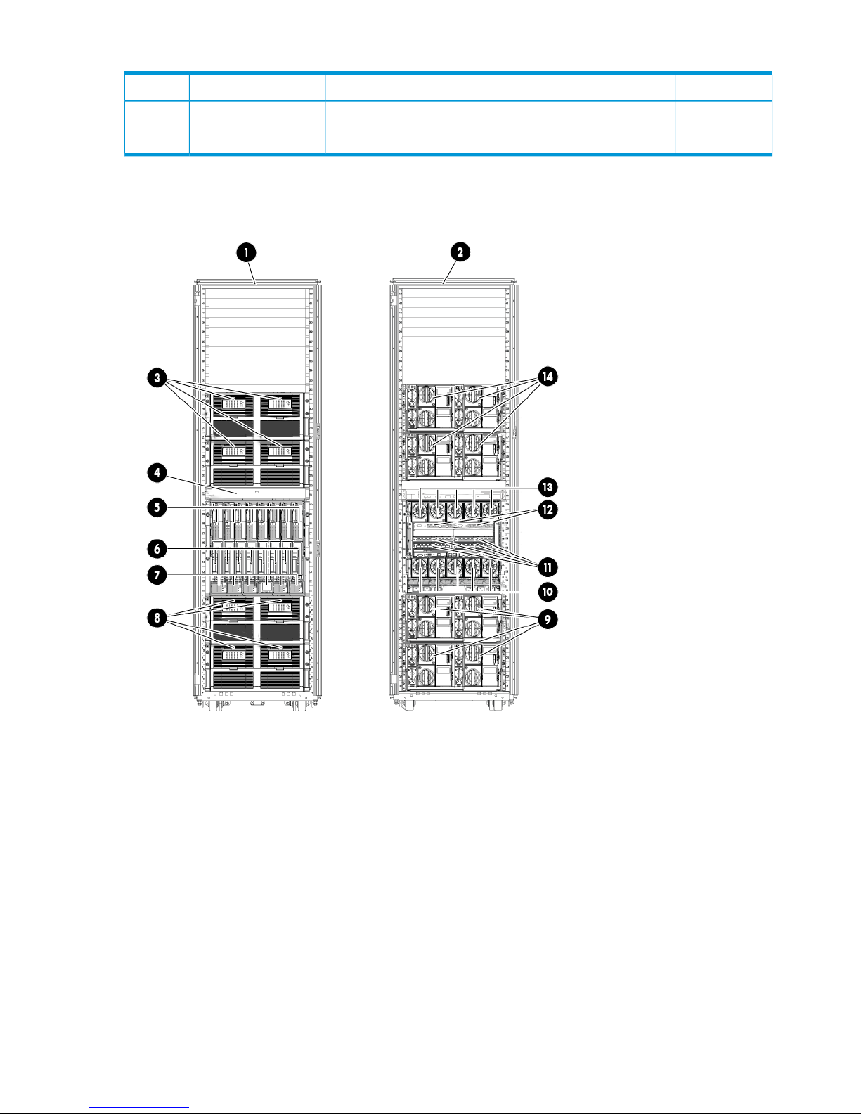
Table 5 HP StoreAll 9730 Storage system components (continued)
QuantityDevice SpecificationsModelItem
• 70 HP 3 TB 7.2 DP MDL SAS HDDs
• 210 TB raw, 150 TB after RAID
Figure 16 (page 20) shows the HP StoreAll 9730 Storage system (front and back).
Figure 16 HP StoreAll 9730 storage solution
2. HP StoreAll 9730 (back)1. HP StoreAll 9730 (front)
4. KVM (front)3. MDL SAS capacity blocks 3 and 4 (back)
6. Bay 9 through 16 (front)5. Bay 1 through 8 (front)
8. Capacity blocks 1 and 2 (front)7. Power supplies
10. Fans (back)9. Capacity blocks 1 and 2 (back)
12. HP VC Flex-10 Ethernet modules11. SAS switches
14. Capacity blocks 3 and 4 (front)13. Fans (back)
20 Setting up and installing HP StoreAll hardware
Page 21

Installing HP StoreAll Storage system hardware components into a rack
New HP StoreAll 9730 Storage systems are typically delivered with all appliances and devices
installed into rack systems. HP StoreAll 8800, 9320, and 9730 Storage systems may or may not
be delivered pre-racked, depending on specific order requests.To install the StoreAll components
(server and storage) into the rack, see the rail kit instructions that shipped with your product.
NOTE: Before installing any hardware components, complete the forms in “Installation checklists”
(page 178) to collect necessary information related to site and hardware installation requirements.
Selecting an HP cabinet and determining HP StoreAll component locations within the
rack
The HP StoreAll 9320 and 9300 Storage systems are compatible with the HP Intelligent Series
42U extended, 36U, and 22U Rack, while the HP StoreAll 9730 Storage system is compatible
with the HP Intelligent Series 42U Rack. For the HP StoreAll 8200 and 8800 Storage systems, HP
rack use is optional; however, if a rack is used, the HP Intelligent Series Rack (42U extended, 36U
and 22U heights) is compatible. The default rack for the HP StoreAll 8200 Gateway Storage system
is the HP 642 Intelligent Series Rack.
CAUTION: HP has not tested or validated the HP MDL SAS capacity blocks with any third-party
racks. Before installing the MDL SAS capacity blocks in a third-party rack, properly scope the
limitations of the rack and consider the following:
• You must fully understand the static and dynamic load carrying capacity of the rack and be
sure that it can accommodate the weight of the MDL SAS capacity blocks.
• You must install a 1U tray beneath the MDL SAS capacity blocks to ensure proper support.
• Be sure sufficient clearance exists for cabling, installation and removal of the enclosure,
actuation of the rack doors, and full articulation of the drive drawers.
Before you install HP StoreAll rack components
WARNING! To reduce the risk of personal injury, electrical shock, or damage to the equipment,
adhere to the specified safety guidelines.
Disk enclosures are populated with disks before shipment, and each disk is assigned specifically
to a designated bay in the enclosure. If disks are removed from the enclosure, they must be inserted
in the same bay from which they were removed. When removing disks, affix a numbered label
on each disk to track which disk belongs to which bay. If the disks are not placed in their original
bays, disk formatting is lost, and each disk must be reformatted. Disk reformatting can take up to
24 hours to complete.
Before you begin installing rack and rack components, note the following safety precaution
guidelines:
• Power cords are unplugged from equipment. In some cases, the Power On/Standby button
does not completely shut off the equipment.
• You have already planned the rack position for all HP StoreAll components before installing
them.
• At least two people lift the storage system during removal or installation if the weight exceeds
22.7 kg (50 lb). If the system is being loaded into the rack above chest level, a third person
MUST assist with aligning the system with the rails while the other two people support the
weight of the system.
• Leveling jacks on the rack are properly extended to the floor.
• The full weight of the rack rests on the leveling jacks.
Installing HP StoreAll Storage system hardware components into a rack 21
Page 22
• The stabilizing feet are attached to the rack if it is a single-rack installation.
• Any adjacent racks are securely coupled together in multiple-rack installations.
• Only one component in a rack is extended at a time during installation and operation. A rack
might become unstable if more than one component is extended.
• Devices are fully and properly supported and level when sliding them into the rack. Do not
extend the hard drive drawers beyond the supporting surface when the unit is not installed in
a rack.
• Follow industry-standard recommendations.
See “Understanding platform configurations” (page 9) and “Installing HP StoreAll Storage system
hardware components into a rack” (page 21) for cabling and additional component information.
Disk drive layouts
Some items to note about disk drive layouts:
• Pools do not span a drive drawer in the MDL SAS capacity block.
• Pools do not span enclosures in the ENT SAS capacity block.
• All drives in a single MDL SAS capacity block must be of the same capacity.
• All drives in a group of ENT SAS capacity blocks (up to 4) must be of the same capacity.
NOTE: For information about 3PAR drive layouts, see the HP 3PAR StoreServ documentation.
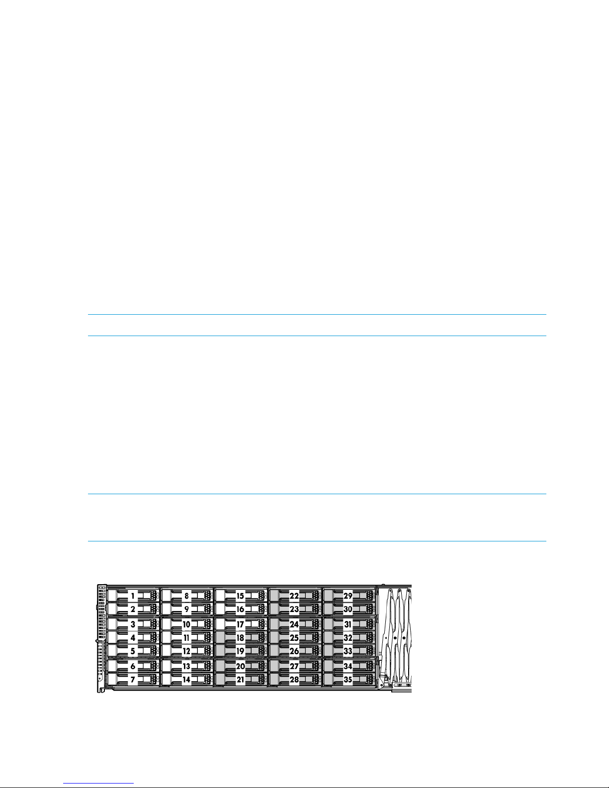
The drive configuration of a half-populated MDL SAS capacity block (indicated by the shading in
Figure 17 (page 22)):
• Spare drive in bay 35
• 8–drive pool (bays 18–25)
• 9–drive pool (bays 26–34)
A fully populated MDL SAS capacity block has the same drive configuration as the half-populated
capacity block with the following additions:
• 8–drive pool (bays 1–8)
• 9–drive pool (bays 9–17)
NOTE: The figure for the MDL SAS capacity block shows the option of the half populated enclosure
(drives 18–35, indicated by the shading). The other option is a fully populated enclosure (all 35
drives).
Figure 17 Disk drive layout for the MDL SAS capacity block
22 Setting up and installing HP StoreAll hardware
Page 23
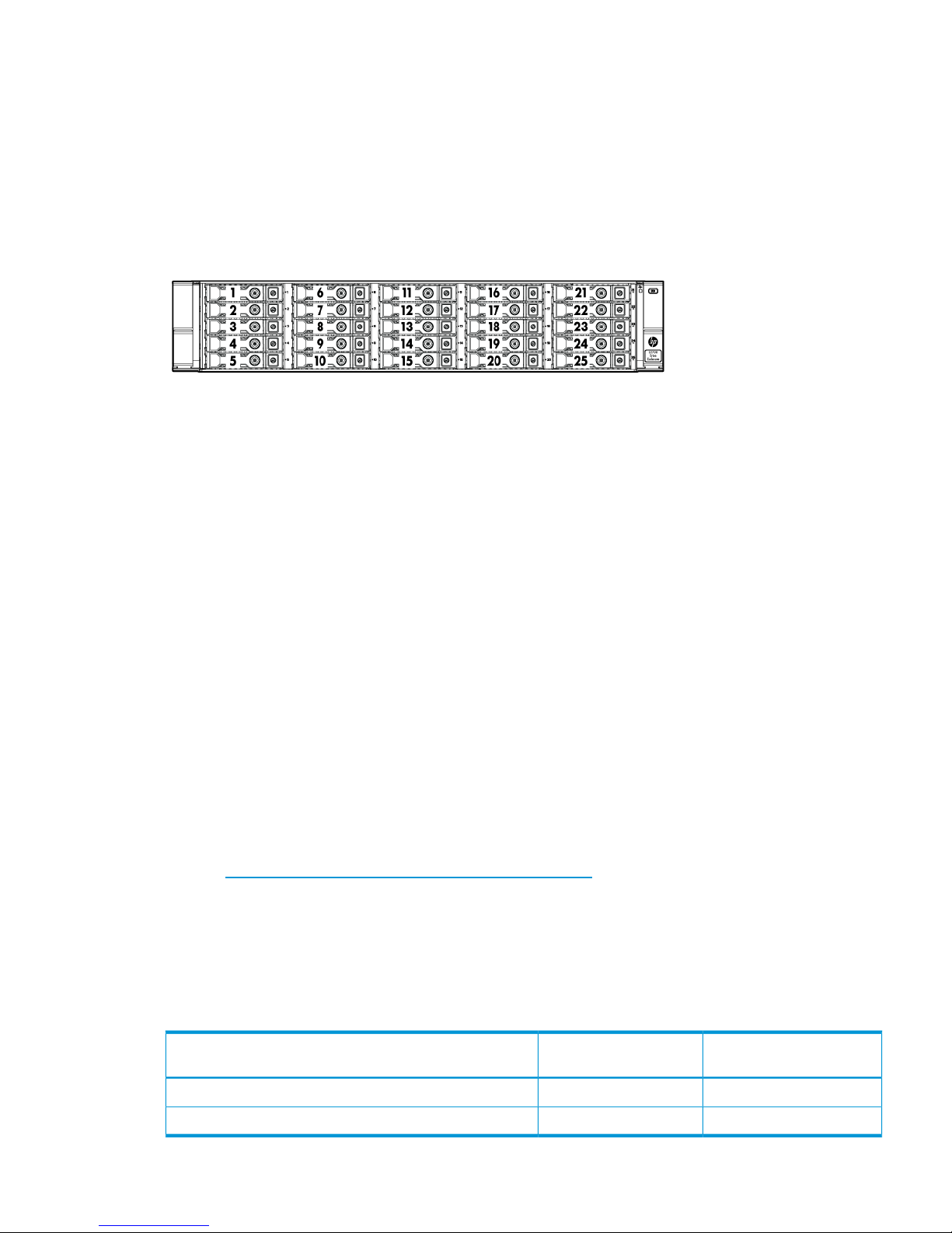
An ENT SAS capacity block has a fully populated (25 drives) disk enclosure with 1 spare in bay
1. It contains 4 pools with 6 drives each:
• Bays 2–7
• Bays 8–13
• Bays 14–19
• Bays 20–25
Figure 18 Disk drive layout for the ENT SAS capacity block
Understanding network connections
The following sections provide network layout information for HP Store All 8xxx, 93xx, and 9730
Storage systems.
HP StoreAll 8xxx and 93xx hardware network layout information
When installing the HP StoreAll OS Software, users can create either a flat network (also referred
to as a unified network) or dual network when using HP StoreAll 8800, 8200, 9300, and 9320
Storage systems.
• Flat Networking. In creating a flat network, the HP StoreAll OS Software creates one combined
cluster and user network. One single bonded interface (Bond0) is used for all network traffic.
• Dual Networking. In creating a dual network, HP StoreAll creates separate networks for cluster
and user traffic. In doing so, two bonded interfaces (Bond0 and Bond1) are created.
Note that only one IP address exists per server by default, and the IP address exists on the public
network. The flat network creates Bond0 on specific interfaces. For 10 GbE systems, Bond0 uses
eth4/eth5 interfaces. For Quad GbE systems, Bond0 uses interfaces eth4 through eth7.
If necessary, create separate user and cluster networks, with Bond0 as the cluster network and
Bond1 as the user network. The initial installation configures Bond0 on the default interfaces.
Later, you can customize Bond0, selecting the correct interfaces for your network and can then
define Bond1.
See the HP StoreAll Storage Network Best Practices Guide for a detailed description of the flat
network on 9300/9320 systems, including the physical layout of the network.
If you create a flat network, by default, all four 10 Gb ports are used with the 10 Gb NIC and all
8 ports with the 1 Gb NIC.
During the HP StoreAll OS Software installation process, bonding requirements must be set. Note
the default bonding and network layouts for the HP StoreAll 8200 and 8800 Storage systems.
Table 6 Default bonding for the HP StoreAll 8200 and 8800 Storage systems
Default bond mode
Installed network
controllerHP StoreAll Storage system
Mode 6 (default)1 GbEHP StoreAll 8800/8200
Mode 1 (default)10 GbEHP StoreAll 8800/8200
Understanding network connections 23
Page 24
Default bond modes are Mode 1 and Mode 6 because these modes do not require any special
configuration for the network switches. HP recommends using Mode 4 for increased bandwidth
transfer rate by merging all ports into one data path. Using Mode 4 requires additional network
configuration.
The following figures show the network port configuration for HP StoreAll 8800 1 GbE and 10
GbE storage.
Figure 19 HP StoreAll 8800 1 GbE network ports
6. eth9 (port 2)1. eth7 (port 4)
7. eth10 (port 3)2. eth6 (port 3)
8. eth11 (port 4)3. eth5 (port 2)
9. eth0 (port 1)4.eth4 (port 1)
10. eth1 (port 2)5. eth8 (port 1)
Figure 20 HP StoreAll 8800 10 GbE network ports
1. eth5 (port 2)
2. eth4 (port 1)
3. eth6 (port 1)
4. eth7 (port 2)
5.eth0 (port 1)
6. eth1 (port 2)
Table 7 (page 25) provides configuration details for default network configurations additionally
supported by the HP StoreAll installation.
24 Setting up and installing HP StoreAll hardware
Page 25

Table 7 HP StoreAll 8200 and 8800 Storage system network layout
Default bond
modeEthernet devicesNetwork name
Number of
networksDevice description/networkingLayout
Mode 1eth4, eth5,bond0
1
Flat
1
eth6, eth7(Combined Cluster/User)
10 GbE
Mode 1eth4, eth6bond0
2
Dual
2
Mode 1eth5, eth7bond1(Separate Cluster/User
10 GbE
Mode 6eth,4, eth5, eth6,
eth7
bond0
1
Flat
(Combined Cluster/User)
3
eth8, eth9, eth10,
eth11
1 GbE
Mode 6eth4, eth5, eth8,
eth9
bond0
bond1
2
Dual
(Separate Cluster/User)
4
Mode 6
eth6, eth7, eht10,
eth11
1 GbE
Mode 6eth4, eth5, eth6,
eth7
bond0
bond2
2
Flat
10 GbE
5
Mode 6
eth0, eth1
Separate iLO Network
Mode 1eth4, eth6bond0
3
Dual
6
Mode 1eth5, eth7bond110 GbE
Mode 6eth0, eth1bond2Separate iLO Network
Mode 6eth,4, eth5, eth6,
eth7
bond0
bond2
2
Flat (Combined Cluster/User)
1 GbE
7
Mode 6
eth8, eth9, eth10,
eth11
Separate iLO Network
eth0, eth1
Mode 6eth4, eth5, eth8,
eth9
bond0
bond1
3
Dual (Combined Cluster/User)
1 GbE
8
Mode 6
eth6, eth7, eht10,
eth11
bond2Separate iLO Network Mode 6
eth0, eth1
HP StoreAll 8xxx and 93xx Storage system prerequisites
Make sure that the following information is available before configuring the network with the
StoreAll Installation Wizard.
For flat networking:
• One IP address per server to assign to the cluster network
• One IP address per server to assign to the iLO interface
• One virtual IP address (VIF) to assign to the entire cluster for management use
• The IP addresses of your DNS servers
• The IP addresses of your NTP servers
Understanding network connections 25
Page 26

For dual networking:
• One IP address for the cluster network
• One IP address per server to assign to the iLO interface
• One IP address for the user network
• One IP address for both the cluster and user network for the Fusion Manager GUI Virtual
Interface (VIF) and VIP IP address for both user and cluster network.
• The IP addresses of your DNS servers
• The IP addresses of your NTP servers
HP StoreAll 9730 network layouts
While installing the HP StoreAll OS Software, users can create either a flat network (also referred
to as a unified network) or dual network when using the HP StoreAll 9730 Storage system.
• Flat Networking. In creating a flat network, the HP StoreAll OS Software creates one combined
cluster and user network. One single bonded interface (Bond0) is created used for all network
traffic and uses all available ports on an HP StoreAll node.
• Dual Networking. In creating a dual network, HP StoreAll creates separate networks for cluster
and user traffic. In doing so, two bonded interfaces (Bond0 and Bond1) are created.
The HP StoreAll 9730 Storage system supports four networking layouts. The default is to use a flat
(single, unified) network for all cluster and user traffic. The other layouts provide a dedicated
management network, a user/cluster network, and, optionally, additional user networks. To use
a network layout other than the default, you must specify the number of networks needed to run
the 9730 Setup Wizard.
NOTE: Use layout 2 when adding an HP StoreAll 9730 Storage system to an existing 2-network
HP StoreAll cluster.
See the HP StoreAll Storage Network Best Practices Guide for detailed information about the
network layouts.
Table 8 Supported HP StoreAll 9730 Storage system network layouts
Bond speedEthernet
devices
Network
name
Number of
networks
DescriptionLayout
10 GBeth0, eth3Bond01Unified network (default)1
1 GBeth0, eth3Bond02Dedicated management network2
9 GBeth1, eth2Bond1User/cluster network
1 GBeth0, eth3Bond03Dedicated management network3
4.5 GBeth1, eth2Bond1User/cluster network
4.5 GBeth4, eth5Bond2User2 network
1 GBeth0, eth3Bond04Dedicated management network4
3.5 GBeth1, eth2Bond1User/cluster network
3.5 GBeth4, eth5Bond2User2
2 GBeth6, eth7Bond3User3
26 Setting up and installing HP StoreAll hardware
Page 27

IMPORTANT:
• HP StoreAll 9730 Storage systems default to a flat network configuration that places the chassis
management components on one subnet and the user/cluster components on a separate
subnet. Nodes are configured to access the user, cluster, and management networks through
a single bond attached to the user/cluster subnet. Node access to the components on the
management subnet requires a route in the customer network that connects the management
and user/cluster subnets.
• The default flat network layout requires the configuration of a router to provide a level-3 route
that connects the user/cluster subnet and the management subnet. The setup process does not
complete if the level-3 route is not in place for system installation. During the setup process,
the installer software makes sure that it can ping the OA to verify the route between the
user/cluster and management subnets. If the verification is unsuccessful, the installer software
prompts the user to correct the problem before proceeding.
IP address requirements for flat (unified) networks
Obtain the following IP addresses when performing the installation for the flat (unified) network.
The HP StoreAll Storage Network Best Practices Guide describes the components in more detail,
and also lists IP address requirements for the other supported network layouts.
Table 9 IP addresses for HP StoreAll 9730 flat (unified) network layout
Maximum number of
addressesMinimum number of addressesSubnetComponent
11 (one virtual IP address to assign to the entire
cluster for management use)
user/clusterCluster management VIF
Variable. At least 1
per node (16 included
in total)
2 ( virtual IP address for failover)user/clusterUser VIF
162 (one IP address per server to assign to the
network bond)
user/clusterNodes
1616managementiLO
88managementInterconnect bays
22 (OA primary and secondary)managementOA module
59 for maximum
configuration
31 for minimum configuration
You also need to provide the IP addresses of the DNS servers, NTP servers, and, optionally, the
default gateway.
HP recommends that you use sequential addresses for the blades, iLOs, and Interconnect.
Understanding network connections 27
Page 28

Cabling HP StoreAll Storage system components
This section provides information on cabling supported HP StoreAll storage system devices. Before
beginning cabling procedures, review applicable warnings and precautions in “Before you install
HP StoreAll rack components” (page 21) and“Limitations and restrictions” (page 7).
Disk enclosure cabling best practices and recommendations
• Use supported SAS cables and power cords.
Table 10 Supported cable requirements
Supported cable
HP StoreAll Storage
system
FC cables (length can vary depending upon placement)8200
8800
◦ HP StoreAll P1228 RAID controller cable (part number 691973-00x), which connects
the RAID controllers to the disk enclosures
◦ 0.5-meter cables (between disk enclosures)
9320
◦ 0.5 meter SAS cables (between disk enclosures)
◦ 2 or 4 meter SAS cables (between disk enclosures and nodes)
2-meter SAS cables9730
• Gather cables in the back of the disk enclosure to ensure that the cabling in the back of the
rack system does not interfere with system operation or maintenance. Bind cables loosely with
cable ties and route the cables out of the way, along the side of the rack. When the cables
are tied together and routed down the side of the rack, system components and indicators
are easily visible and accessible.
• Bind and support cables in a manner that eliminates stress on connectors and tight bends of
the cables. This prevents damage to the connector and cable, and ensures that the connector
remains fully seated in the port.
• Attach a label near both ends of each cable to identify the device connected to that cable.
Include the device, device name, port, or other useful information.
• Use colored markers to color code both ends of each cable, to help visually identify a particular
cable without having to read or locate the label.
• In multipath configurations, you might want to loosely bind the matching pair of cables
connecting devices.
• Only use supported SAS cables with mini-SAS connectors.
• Ensure that the servers or controller enclosures are powered down and power cords are
disconnected before connecting SAS cables to the disk enclosure.
• To connect the initial disk enclosure to the server or controller enclosure, use a standard
mini-SAS cable.
Cabling the HP StoreAll 8200 Gateway system
Note the following guidelines when connecting the HP StoreAll 8200 Gateway to HP 3PAR Storage:
• iSCSI connection is not supported. Only Fibre Channel connection is supported.
• Direct connection configurations are cabled to avoid a single point of failure (SPOF).
• When connecting the StoreAll nodes and the 3PAR storage through switches, ensure that each
FC HBA on each controller (in the node or the storage) connects to a different switch. For
28 Setting up and installing HP StoreAll hardware
Page 29

example, port 1 in slot 2 on each StoreAll node connects to switch 1 and port 2 in slot 2 on
each StoreAll node connects to switch 2. Also, port FC-1 in node 0 of each 3PAR storage
connects to switch 1 and port FC-2 in node 1 of each 3PAR storage connects to switch 2.
(Switches are named 1 and 2 for example purposes only.)
• If cabling an HP StoreAll 8200 Gateway system that uses multiple controllers and an HP 3PAR
StoreServ 7000-series controller without FC switches, connect each server FC HBA to a different
controller to ensure no single point of failure, hardware redundancy, and multipath capability.
• If cabling an HP StoreAll 8200 Gateway system that uses multiple controllers and an HP 3PAR
StoreServ 7000-series controller with FC switch connectivity to application servers, connect
each server FC HBA to a different switch, and connect each HP 3PAR StoreServ 7000-series
controller to a different switch to ensure no single point of failure within the configuration,
hardware redundancy, and multi-path capability.
• When cabling the HP 3PAR StoreServ 10000-series controllers to HP StoreAll 8200 Gateway
systems, note that three internal buses exist in each controller node. See the adapter installation
requirements in Table 11 (page 29) and Table 12 (page 29).
Table 11 PCI Bus/PCI slot association
PCI 3PCI 2PCI 1
SLOT 8SLOT 7SLOT 6SLOT 5SLOT 4SLOT 3SLOT 2SLOT 1SLOT 0
Table 12 Adapter installation order and usage based on controller node type
Installation order by PCI slotUsage (adapter type)
6, 3, 0Drive chassis connections
(Fibre Channel adapters)
2, 5, 8, 1, 4, 7Hosts connections
(Fibre Channel adapters)
1, 4, 2, 3RCFC connections
E1Remote Copy
(RCIP ports built-in)
See the HP 3PAR StoreServ 10000 Storage Installation and Deinstallation Guide for additional
information on HP StoreAll 8200 and 8800 Storage system connection information and related
HP 3PAR StoreServ device information.
Cabling HP StoreAll Storage system components 29
Page 30
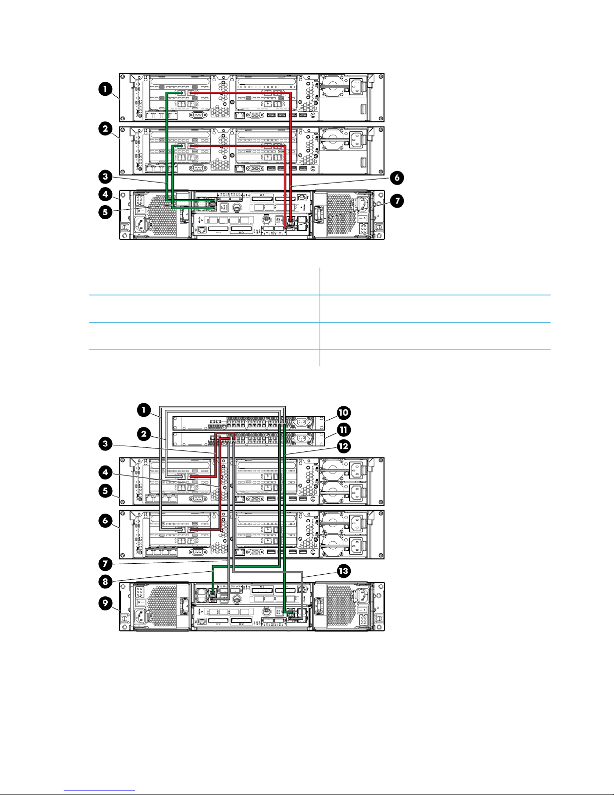
Figure 21 HP StoreAll 8200 with an HP 3PAR StoreServ 7200 (direct connection)
5. HP StoreAll node 1 (port 2, slot 2) to HP 3PAR 7200
(node 1, port FC-1)
1. HP StoreAll node 2 (top)
6. HP StoreAll node 2 (port 1, slot 2) to HP 3PAR 7200
(node 0, port FC-1)
2. HP StoreAll node 1 (bottom)
7. HP StoreAll node 1 (port 1, slot 2) to HP 3PAR 7200
(node 0, port FC-2)
3. HP StoreAll node 2 (port 2, slot 2) to HP 3PAR 7200
(node 1, port FC-2)
4. HP 3PAR StoreServ 7200 (node 0 bottom, node 1 top)
Figure 22 HP StoreAll 8200 with an HP 3PAR StoreServ 7200 and FC switches
8. Switch 1, port 4 to 3PAR 7200 node 1, port FC-21. Switch 1, port 1 to HP StoreAll node 1, port 2 in slot
211
9. HP 3PAR StoreServ 7200 (node 1 top, node 0 bottom)2. Switch 1, port 2 to HP StoreAll node 2, port 2 in slot 2
10. Generic switch 1 (top)3. Switch 2, port 1 to HP StoreAll node 2, port 1 in slot 2
11. Generic switch 2 (bottom)4. Switch 2, port 2 to HP StoreAll node 1, port 1 in slot 2
12. Switch 1, port 2 to HP 3PAR 7200 node 0, port FC-15. HP StoreAll node 2 (top)
30 Setting up and installing HP StoreAll hardware
Page 31
13. Switch 2, port 3 to HP 3PAR 7200 node 0, port FC-26. HP StoreAll node 1 (bottom)
7. Switch 2, port 4 to HP 3PAR 7200 node 1, port FC-1
Figure 23 HP StoreAll 8200 with HP 3PAR StoreServ 7400s
5. HP 3PAR StoreServ 7400 storage 2 (bottom)1. HP StoreAll node 2 (top)
6. HP StoreAll node 1, port 2 in slot 2 to HP 3PAR 7400
storage 2 (node 1, port FC-2)
2. HP StoreAll node 1 (bottom)
7. HP StoreAll node 1, port 1 in slot 2 to HP 3PAR 7400
storage 2 (node 0, port FC-1)
3. HP StoreAll node 2, port 2 in slot 2 to HP 3PAR 7400
storage 1 (node 1, port FC-2)
8. HP StoreAll node 2, port 1 in slot 2 to HP 3PAR 7400
storage 1 (node 1, port FC-1)
4. HP 3PAR StoreSev 7400 storage 1 (top)
Cabling HP StoreAll Storage system components 31
Page 32
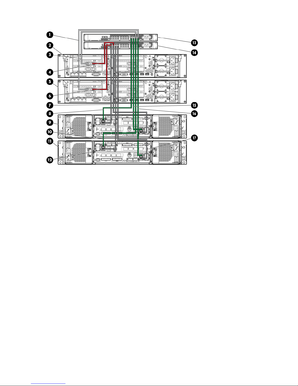
Figure 24 HP StoreAll 8200 with an HP 3PAR StoreServ 7400 and FC switches
10. Switch 1, port 4 to HP 3PAR 7400 storage 2 (node 1,
port FC-2)
1. Switch 1, port 2 to HP StoreAll node 1, port 2 in slot 2
11. HP 3PAR 7400 storage 2 (bottom)2. HP StoreAll node 2 (top)
12. Switch 2, port 4 to HP 3PAR 7400 storage 2 (node 1,
port FC-1)
3. Switch 1, port 1 to HP StoreAll node 2, port 2 in slot 2
13. Generic switch 1 (top)4. Switch 2, port 1 to HP StoreAll node 2, port 1 in slot 2
14. Generic switch 2 (bottom)5. HP StoreAll node 1 (bottom)
15. Switch 1, port 5 to HP 3PAR 7400 storage 1 (node 0,
port FC-1)
6. Switch 2, port 2 to HP StoreAll node 1, port 1 in slot 2
16. Switch 1, port 4 to HP 3PAR 7400 storage 2 (node 1,
port FC-2)
7. Switch 2, port 6 to HP 3PAR 7400 storage 1 (node 1,
port FC-1)
17. Switch 2, port 3 to HP 3PAR 7400 storage 2 (node 2,
port FC-2)
8. Switch 1, port 6 to HP 3PAR 7400 storage 1 (node 1,
port FC-2)
9. HP 3PAR 7400 storage 1 (top)
32 Setting up and installing HP StoreAll hardware
Page 33

Cabling the HP StoreAll 8800 Storage system
Note the following guidelines when connecting the 8800 to MDL SAS or ENT SAS capacity blocks:
• Controller 1 contains ports 1 and 2 in slot 1. Together, these ports form a controller pair.
• Controller 2 contains ports 1 and 2 in slot 4. Together these ports form a controller pair.
The initial connection must be made from controller 1 (port 1 in slot 1) on the StoreAll node.
• Port 1 of each controller (in slot 1 and slot 4) connects to I/O module A on the capacity block.
• Port 2 of each controller (in slot 1 and slot 4) connects to I/O module B on the capacity block.
• Port 1 and port 2 of the same controller (either controller 1 or controller 2) should connect to
different drawers in the MDS SAS capacity block.
• Each controller pair can support a single MDL SAS capacity block or up to 4 ENT SAS capacity
blocks.
• When connecting a SAS chain of up to 4 ENT SAS capacity blocks, port 1 in each controller
pair connects to either I/O module A in the top capacity block or I/O module A in the bottom
capacity block.
• When connecting the capacity blocks together, connect I/O module A on each capacity block
in a "top to bottom" order; connect I/O module B in each capacity block in a "bottom to top"
order.
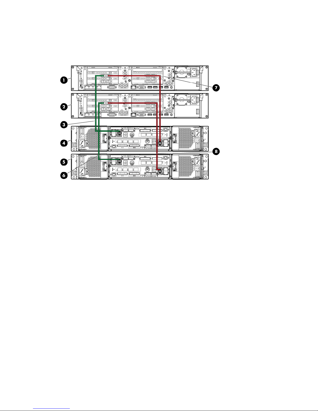
Figure 25 HP StoreAll 8800 Storage system cabling with one ENT SAS capacity block
1. SAS ENT capacity block
2. HP StoreAll node 1, port 2 in slot 1 to SAS ENT capacity block (port 1 of I/O module B)
3. HP StoreAll node 1
4. HP StoreAll node 2
5. HP StoreAll node 2, port 2 in slot 1 to SAS ENT capacity block (port 2 of I/O module B)
6. HP StoreAll node 2, port 1 in slot 1 to SAS ENT capacity block (port 2 of I/O module A)
7. HP StoreAll node 1, port 1 in slot 1 to SAS ENT capacity block (port 1 of I/O module A)
Cabling HP StoreAll Storage system components 33
Page 34

Figure 26 HP StoreAll 8800 Storage system cabling with two ENT SAS capacity blocks
6. HP StoreAll node 21. SAS ENT capacity block 1
7. HP StoreAll node 2, port 2 in slot 1 to SAS ENT capacity
block 2 (port 2, I/O module B)
2. SAS ENT capacity block 2 (port 2, I/O module A) to
SAS ENT capacity block 1 (port 1, I/O module A)
8. HP StoreAll node 2, port 1 in slot 1 to SAS ENT capacity
block 1 (port 2, I/O module A)
3. SAS ENT capacity block 2
9. HP StoreAll node 1, port 1 in slot 1 to SAS ENT capacity
block 2 (port 1, I/O module A)
4. HP StoreAll node 1, port 2 in slot 1 to SAS ENT capacity
block 1 (port 1, I/O module B)
10. SAS ENT capacity block 2 (port 1, I/O module B) to
SAS ENT capacity block 1 (port 2, I/O module B)
5. HP StoreAll node 1
34 Setting up and installing HP StoreAll hardware
Page 35

Figure 27 HP StoreAll 8800 Storage system cabling - full system with ENT SAS capacity blocks
10. ENT capacity block 11. ENT capacity block 8
11. Port 1 of I/O module A on ENT capacity block 8 to
port 1 in slot 4 of HP StoreAll node 1
2. ENT capacity block 7
12. Port 2 of I/O module B on ENT capacity block 8 to
port 2 in slot 4 of HP StoreAll node 2
3. ENT capacity block 6
13. Port 2 of I/O module A on ENT capacity block 5 to
port 1 in slot 4 of HP StoreAll node 2
4. ENT capacity block 5
14. Port 1 in slot 1 of HP StoreAll node 2 to port 2 of I/O
module A on ENT capacity block 1
5. HP StoreAll node 2
15. Port 1 of I/O module B on ENT capacity block 5 to
port 2 in slot 4 of HP StoreAll node 1
6. HP StoreAll node 1
16. Port 1 in slot 1 of HP StoreAll node 1 to port 1 of I/O
module A on ENT capacity block 4
7. ENT capacity block 4
17. Port 2 in slot 1 of HP StoreAll node 2 to port 2 of I/O
module B on ENT capacity block 4
8. ENT capacity block 3
18. Port 2 in slot 1 of HP StoreAll node 1 to port 1 of I/O
module B on ENT capacity block 1
9. ENT capacity block 2
Cabling HP StoreAll Storage system components 35
Page 36

Figure 28 HP StoreAll 8800 Storage system cabling with one MDL SAS capacity block
6. HP StoreAll node 2, port 2 in slot 1 to MDL SAS capacity
block (port 1, I/O module B, Drawer 1)
1. MDL SAS capacity block
7. HP StoreAll node 1, port 1 in slot 1 to MDL SAS capacity
block (port 1, I/O module A, Drawer 1)
2. HP StoreAll node 1, port 2 in slot 1 to MDL SAS capacity
block (port 2, I/O module B, Drawer 2)
8. Port 1 of I/O module A in Drawer 2 to port 2 of I/O
module A in Drawer 1
3. HP StoreAll node 1
9. Port 1 of I/O module B in Drawer 2 to port 2 of I/O
module B in Drawer 1
4. HP StoreAll node 2
5. HP StoreAll node 2, port 1 in slot 1 to MDL SAS capacity
block (port 2, I/O module A, Drawer 2)
36 Setting up and installing HP StoreAll hardware
Page 37

Figure 29 HP StoreAll 8800 Storage system cabling with two MDL SAS capacity blocks
9. Node 2, port 2 in slot 4 to MDL SAS capacity block 2,
drawer 1 (I/O module B, port 1)
1. HP StoreAll node 2
10. Node 2, port 2 in slot 1 to MDL SAS capacity block
1, drawer 1 (I/O module B, port 1)
2. HP StoreAll node 2
11. Node 1, port 1 in slot 1 to MDL SAS capacity block
1, drawer 1 (I/O module A, port 1)
3. Node 1, port 2 in slot 4 to MDL SAS capacity block 2,
drawer 2 (I/O module B, port 2)
12. Port 1 of I/O module A in drawer 2 to port 2 of I/O
module A in drawer 1 of MDL SAS capacity block 2
4. HP SAS MDL capacity block 2 (top)
13. Node 1, port 1 in slot 4 to MDL SAS capacity block
2, drawer 1 (I/O module A, port 1)
5. HP MDL SAS capacity block 1 (bottom)
14. Port 1 of I/O module B in drawer 2 to port 2 of I/O
module B in drawer 1 of MDL SAS capacity block 2
6. Node 2, port 1 in slot 1 to MDL SAS capacity block 1,
drawer 2 (I/O module A, port 2)
15. Port 1 in I/O module A of drawer 2 to port 2 of I/O
module A in drawer 1 of MDL SAS capacity block 1
7. Node 1, port 2 in slot 1 to MDL SAS capacity block 1,
drawer 2 (I/O module B, port 2)
16. Port 1 in I/O module B of drawer 2 to port 2 of I/O
module B in drawer 1 of MDL SAS capacity block 1
8. Node 2, port 1 in slot 4 to MDL SAS capacity block 2,
drawer 2 (I/O module A, port 2)
Cabling HP StoreAll Storage system components 37
Page 38

Figure 30 HP StoreAll 8800 Storage system cabling—Minimum mixed configuration (HP StoreAll
ENT SAS capacity block and HP StoreAll MDL SAS capacity block)
6. MDL SAS capacity block1. SAS ENT capacity block
7. SAS ENT capacity block (port 1, I/O module B) to HP
StoreAll node 1, port 2 in slot 4
2. HP StoreAll node 2, port 1 in slot 1 to MDS SAS capacity
block (port 2, I/O module A, Drawer 2)
8. SAS ENT capacity block (port 1, I/O module A) to HP
StoreAll node 1, port 1 in slot 43. HP StoreAll node 2
9. HP StoreAll node 2, port 2 in slot 1 to MDL SAS capacity
block (port 1, I/O module B, Drawer 1)
4. HP StoreAll node 1
10. HP StoreAll node 1, port 1 in slot 1 to MDL SAS
capacity block (port 1, I/O module A, Drawer 1)
5. HP StoreAll node 1, port 2 in slot 1 to MDL SAS capacity
block (port 2, I/O module B, Drawer 2
38 Setting up and installing HP StoreAll hardware
Page 39
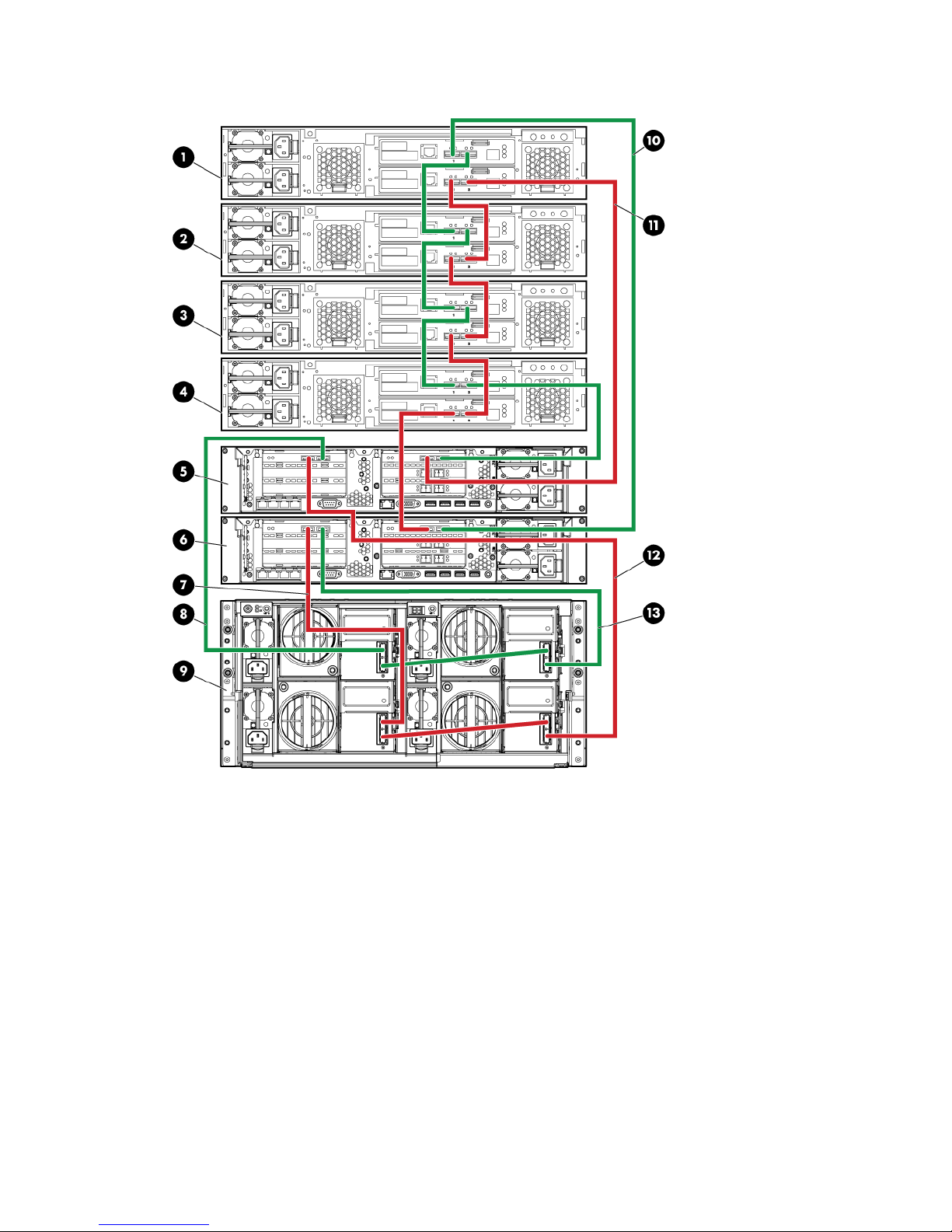
Figure 31 HP StoreAll 8800 Storage system cabling - Mixed configuration (HP StoreAll SFF ENT
SAS capacity block and HP StoreAll SFF MDL SAS capacity block)
8. Port 1 in slot 1 of HP StoreAll node 2 to the MDL SAS
capacity block, drawer 2 (I/O module A, port 2)
1. SFF ENT SAS capacity block 4
9. HP MDL SAS capacity block (drawer 2 on the left,
drawer 1 on the right)
2. SFF ENT SAS capacity block 3
10. Port 1 of I/O module A on SFF ENT SAS capacity block
4 to port 1 in slot 4 of HP StoreAll node 1
3. SFF ENT SAS capacity block 2
11. Port 2 of I/O module B on SFF ENT SAS capacity block
5 to port 2 in slot 4 of HP StoreAll node 2
4. SFF ENT SAS capacity block 1
12. Port 2 in slot 1 of HP StoreAll node 2 to the MDL SAS
capacity block, drawer 1 (I/O module B, port 1)
5. HP StoreAll node 2
13. Port 1 in slot 1 of HP StoreAll node 1 to the MDL SAS
capacity block, drawer 1 (I/O module, port 1)
6. HP StoreAll node 1
7. Port 2 in slot 1 of HP StoreAll node 1 to the MDL SAS
capacity block, drawer 2 (I/O module B, port 2)
Cabling HP StoreAll Storage system components 39
Page 40

40 Setting up and installing HP StoreAll hardware
Page 41

Cabling the HP StoreAll 9320 Storage system
This section provides details on how to cable HP StoreAll 9320 Storage system components.
NOTE: Because the HP StoreAll 9300 and 9320 Storage systems use similar components, cabling
for both systems is identical.
Figure 32 HP StoreAll 9320 cabling-QP330B (1 Disk Enclosure Group [DEG]/1 Performance Block
and 1 Starter Kit)-back
1. HP StoreAllnode 1 (top) and node 2 (bottom)
2. HP StoreAll SFF capacity block
3. HP StoreAllnode 1 SAS HBA-to-capacity block module A SAS 1 (top green)
4. HP StoreAll node 1 SAS HBA-to-capacity block module B, SAS 1
5. HP StoreAll node 2 SAS HBA-to-capacity block module A SAS 2
6. HP StoreAll node 2 SAS HBA-to-capacity block module B SAS 2
Cabling HP StoreAll Storage system components 41
Page 42
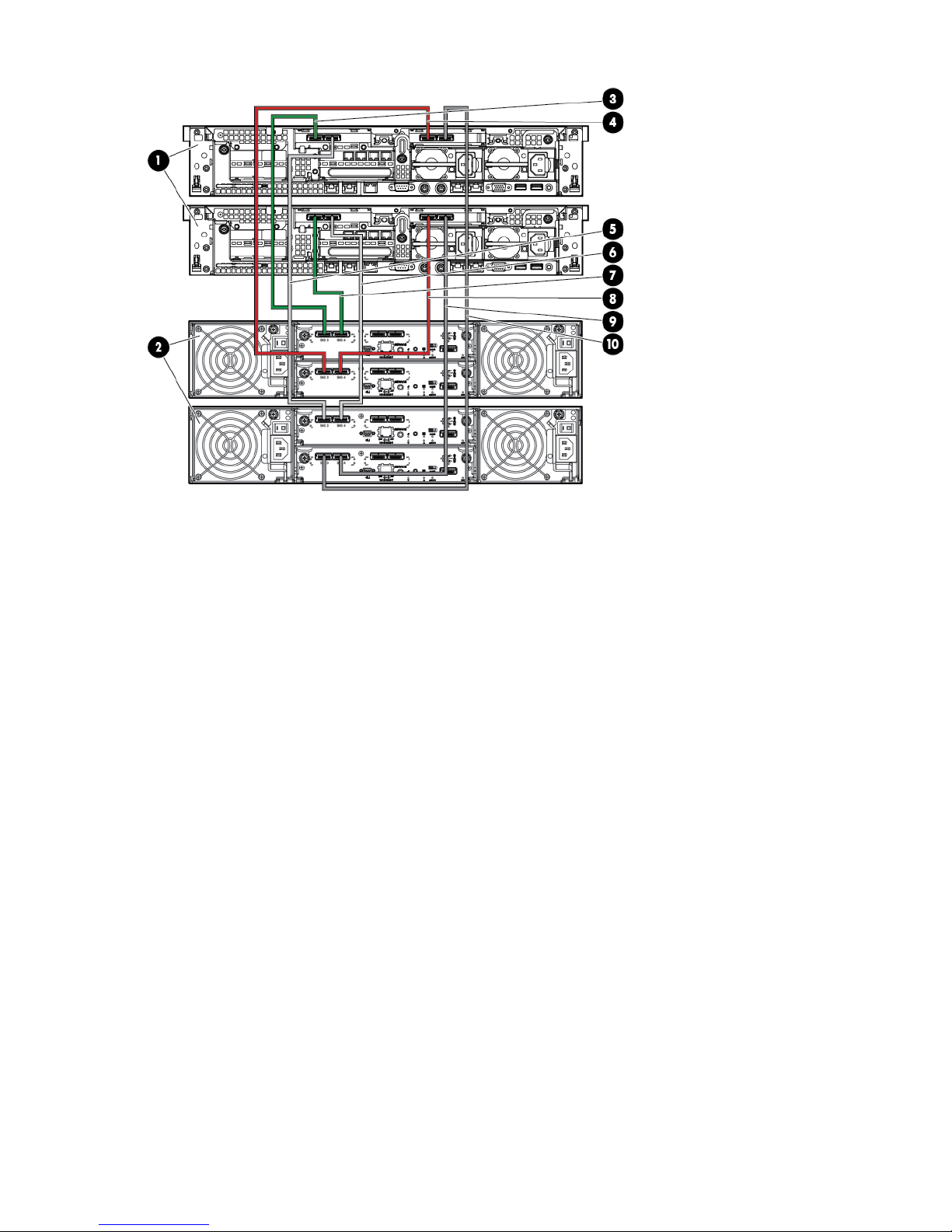
Figure 33 HP StoreAll 9320 cabling-QP330B (2 DEGs/1 Performance Block and 2 Starter Kits)-back
2. HP StoreAll capacity block 1 (top and capacity block 2
(bottom)
1. HP StoreAll node 1 (top) and node 2 (bottom)
4. HP StoreAll node 1 SAS HBA 1, module B-to-capacity
block 1, module B, SAS 1
3. HP StoreAll node 1 SAS HBA 1, module A-to-capacity
block 1, module B, SAS 1
6. HP StoreAll node 2 SAS HBA 2, module A-to-capacity
block 2, module A, SAS 2
5. HP StoreAll node 1 SAS HBA 2 module A-to-capacity
block 2, module B, SAS 1
8. HP StoreAll node 2 SAS HBA 1, module B-to-capacity
block 1, module B, SAS 2
7. HP StoreAll node 2 SAS HBA 2, module A-to-capacity
block 1, module A, SAS 2
10. HP StoreAll node 2 SAS HBA 2, module B-to-capacity
block 2, module B, SAS 2
42 Setting up and installing HP StoreAll hardware
Page 43

Figure 34 HP StoreAll 9320 cabling-QP331B (1 DEGs/1 Performance Block and 1 Starter Kit)-back
1. HP StoreAll node 1 (top) and node 2 (bottom)
2. HP StoreAll capacity block
3. HP StoreAll node 1 SAS HBA-to-capacity block, module A, SAS 1
4. HP StoreAll node 1 SAS HBA-to-capacity block, module B, SAS 1
5. HP StoreAll node 2 SAS HBA-to-capacity block, module A, SAS 2
6. HP StoreAll node 2 SAS HBA-to-capacity block, module B, SAS 2
Cabling HP StoreAll Storage system components 43
Page 44

Figure 35 HP StoreAll 9320 cabling-QP331B (2 DEGs/1 Performance Block and 2 Starter Kits)-back
2. HP StoreAll capacity block 11. HP StoreAll node 1 (top) and node 2 (bottom)
4. HP StoreAll node 1 SAS HBA-to-capacity block 1, module
A, SAS 1
3. HP StoreAll node 1 SAS HBA-to-capacity block 2, module
A, SAS 1
6. HP StoreAll node 2 SAS HBA-to-capacity block 1, module
A, SAS 2
5. HP StoreAll node 1 SAS HBA-to-capacity block 1, module
B, SAS 1
8. HP StoreAll node 2 SAS HBA-to-capacity block 2, module
A, SAS 2
7. HP StoreAll node 2 SAS HBA-to-capacity block B, module
A, SAS 2
10. HP StoreAll node 1 SAS HBA-to-capacity block 2,
module B, SAS 1
9. HP StoreAll node 2 SAS HBA-to-capacity block 2, module
B, SAS 2
44 Setting up and installing HP StoreAll hardware
Page 45
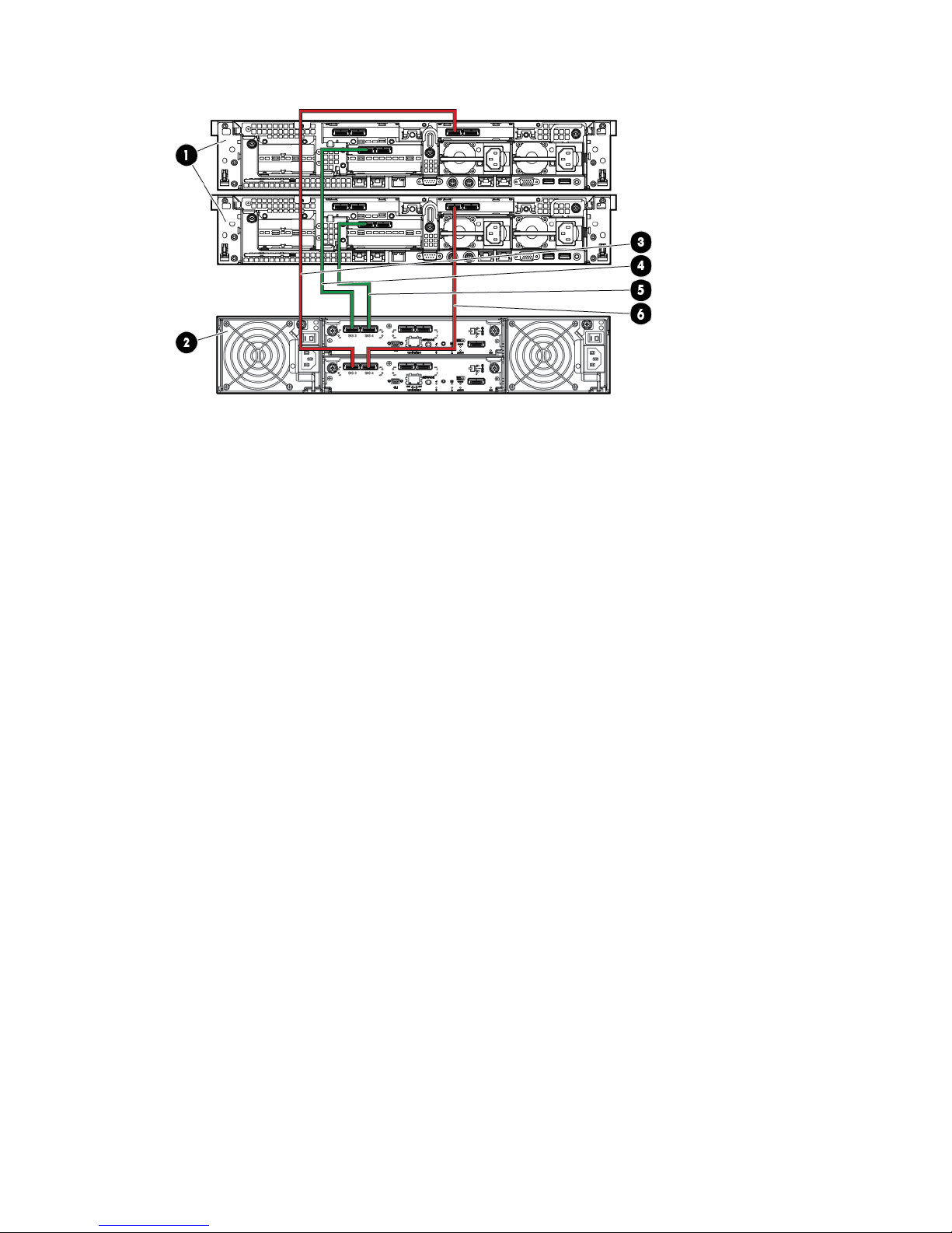
Figure 36 HP StoreAll 9320 cabling-QP332B (1 DEG/1 Performance Block and 1 Starter Kit)-back
2. HP StoreAll capacity block1. HP StoreAll node 1 (top) and node 2 (bottom)
4. HP StoreAll node 1 SAS HBA-to-MSA, module A, SAS
1
3. HP StoreAll node 1 SAS HBA-to-capacity block, module
B, SAS 1
6. HP StoreAll node 2 SAS HBA-to-capacity block, module
B, SAS 2
5. HP StoreAll node 2 SAS HBA-to-capacity block, module
A, SAS 2
Cabling HP StoreAll Storage system components 45
Page 46
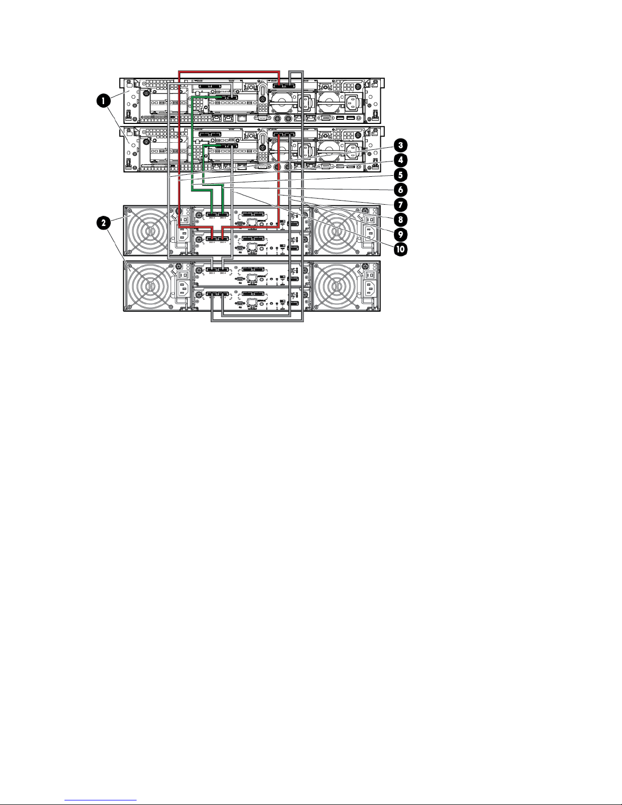
Figure 37 HP StoreAll 9320 cabling-QP332B (2 DEGs/1 Performance Block and 2 Starter Kits)-back
2. HP StoreAll capacity block 1 (top) and 2 (bottom)1. HP StoreAll node 1 (top) and node 2 (bottom)
4. HP StoreAll node 1 SAS HBA-to-capacity block 1, module
B, SAS 1
3. HP StoreAll node 1 SAS HBA-to-capacity block 2, module
B, SAS 1
6. HP StoreAll node 1, NIC 1-to-capacity block 1, module
A, SAS 1
5. HP StoreAll node 1, NIC 3-to-capacity block 2, module
A, SAS 1
8. HP StoreAll node 2 SAS HBA-to-capacity block 2, module
A, SAS 2
7. HP StoreAll node 2, SAS HBA-to-capacity block 1,
module A, SAS 2
10. HP StoreAll node 2 SAS HBA-to-capacity block 2,
module B, SAS 2
9. HP StoreAll node 2 SAS HBA-to-capacity block 1, module
B, SAS 2
46 Setting up and installing HP StoreAll hardware
Page 47
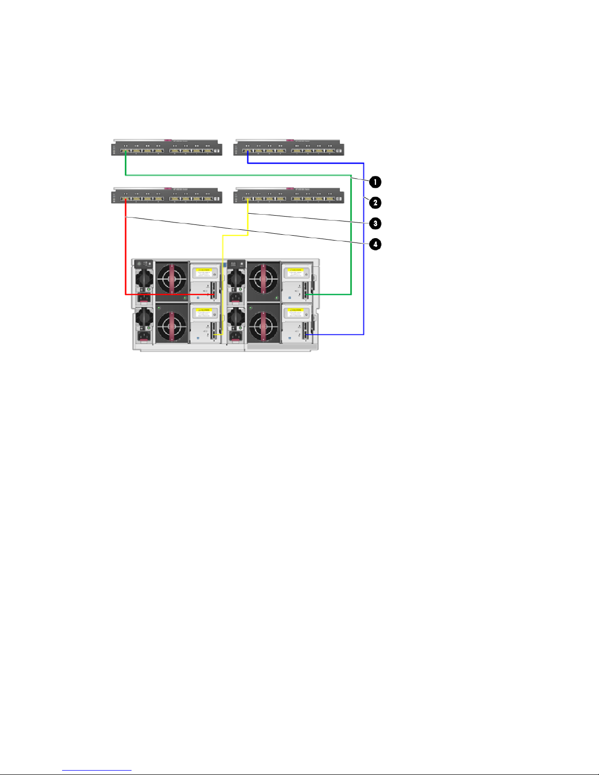
Cabling the HP StoreAll 9730 Storage system
This sections provides information how to cable an HP StoreAll 9730 Storage system. Information
on cabling a couplet and a fully-loaded system is provided. Fully-loaded cabling follows the same
construction for systems with 2 to 8 couplet systems.
Figure 38 HP StoreAll 9730 Storage system with 1 couplet SAS cable routing (back)
2. SAS Switch bay 6 (top right)-MDL SAS capacity block
1, drawer 1, B1, port 1 (bottom right)
1. SAS switch bay 5 (top left)-MDL SAS capacity block 1,
drawer 1, A1, port 1 (top right)
4. SAS Switch bay 8 (bottom right)-MDL SAS capacity block
1, drawer 2, B2, port 1 (bottom left)
3. SAS switch bay 7 (bottom left) -MDL SAS capacity block
1, drawer 2, A2, port 1 (top left)
Cabling HP StoreAll Storage system components 47
Page 48
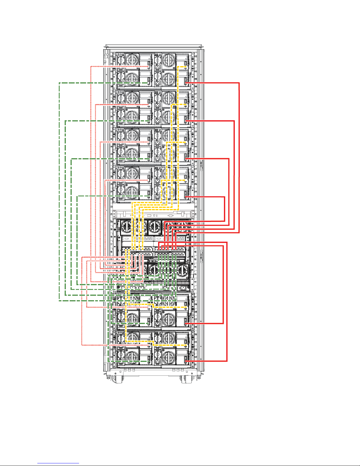
Figure 39 HP StoreAll 9730 Storage system cabling for a fully-loaded rack—capacity block-to-switch
cabling (back)
Cabling verification (8800 and 9730 only)
For HP StoreAll 8800 and HP StoreAll 9730 systems, once you have secured all of the cabling
connections, run a cabling check:
sascheck
48 Setting up and installing HP StoreAll hardware
Page 49

Example response when the cabling set up has been successful:
SUCCESS: The SAS cables are connected and configured properly.
Example response when the cabling set up has been unsuccessful:
ERROR: The Controller in the PCI Slot 4 of this node could not see the peer controller.
Ensure that the peer controller is in a healthy state.
ERROR: Port 1 of I/O Module Slot A of Drawer 1 of the D6000 attached to the Controller in the PCI Slot 4 is
either not completely connected or not connected at all.
Ensure that the connections conform to the supported configuration and that the connections are fully seated.
ERROR: Port 2 of I/O Module Slot B of Drawer 2 of the D6000 attached to the Controller in the PCI Slot 4 is
either not completely connected or not connected at all.
Ensure that the connections conform to the supported configuration and that the connections are fully seated.
Power on
After cabling verification, HP recommends that you power on your system before continuing on to
install the HP StoreAll OS software.
1. Power on the disk enclosures. Wait for the enclosures to fully power on and check for green
status indicators.
2. Power on the servers (make sure the storage devices are turned on first).
Power on 49
Page 50

3 Installing the HP StoreAll OS Software and configuring
the HP StoreAll Storage system
This chapter provides instructions for installing and configuring the HP StoreAll OS Software on
HP StoreAll Storage systems. During this portion of the installation, you must download the ISO or
IMG file of the HP StoreAll OS Software, create a bootable device, install the HP StoreAll OS
Software, and then configure the HP StoreAll Storage system.
Table 13 HP StoreAll OS Software installation steps for the 8xxx and 93xx
More informationTaskStep
Prepare for the installation.1.
• “Installation checklists” (page 178)
• “Creating a bootable device and installing the
HP StoreAll OS Software” (page 51)
• “Before you begin configuring HP StoreAll 8xxx
and 93xx Storage systems” (page 55)
Configure the HP StoreAll system.2.
• “Configuring nodes and a cluster on the HP
StoreAll 8xxx and 93xx Storage system”
(page 58)
• “Configuring clusters remotely with the Getting
Started Wizard” (page 105)
• “Discovering and configuring HP StoreAll
servers and their storage” (page 127)
“Configuring virtual IP addresses” (page 144)Set up HP StoreAll virtual IP addresses for client access.3.
Perform post-installation tasks.4.
• “Post-installation tasks” (page 149)
• “Installing and configuring HP StoreAll clients
for Linux and Windows (optional)” (page 158)
Configure optional features.5.
• “Installing and configuring HP StoreAll clients
for Linux and Windows (optional)” (page 158)
• “Expanding an existing HP StoreAll Storage
system using the Setup Wizard” (page 207)
“Installing and configuring the HP StoreAll Linux
client” (page 158)
Configure HP StoreAll clients for Linux or Windows
(optional).
6.
50 Installing the HP StoreAll OS Software and configuring the HP StoreAll Storage system
Page 51

Table 14 (page 51) provides an overview of the installation steps necessary for the HP StoreAll
9730 Storage system and provides links to specific step-by-step procedures.
Table 14 Overview of HP StoreAll OS Software installation steps for the HP StoreAll 9730
More informationTaskStep
Review pre-installation information.1.
• “Creating a bootable device and installing the
HP StoreAll OS Software” (page 51)
• “Before you begin configuring HP StoreAll
9730 Storage systems” (page 74)
“Configuring OA1 IP addresses for the Onboard
Administrator” (page 77)
Configure active and standby IP addresses for Onboard
Administrator.
2.
Configure the HP StoreAll system.3.
• “Configuring the chassis on the HP StoreAll
9730 Storage system” (page 79)
• “Configuring clusters remotely with the Getting
Started Wizard” (page 105)
• “Discovering and configuring HP StoreAll
servers and their storage” (page 127)
“Configuring virtual IP addresses” (page 144)Set up virtual IP addresses for client access.4.
“Post-installation tasks” (page 149)Perform post-installation tasks.5.
“Installing and configuring HP StoreAll clients for
Linux and Windows (optional)” (page 158)
Complete optional post installation tasks (if necessary).6.
“Installing and configuring the HP StoreAll Linux
client” (page 158)
Configure StoreAll clients for Linux or Windows (optional).7.
Complete optional post-installation tasks (if necessary).8.
• “Installing and configuring HP StoreAll clients
for Linux and Windows (optional)” (page 158)
• “Expanding an existing HP StoreAll Storage
system using the Setup Wizard” (page 207)
• “Installing an HP StoreAll Storage 9730 system
Performance Module with the Setup Wizard”
(page 240)
NOTE: Before you begin the installation, complete the forms in “Installation checklists” (page 178)
to collect necessary information related to specific installation requirements. Since you may need
to recall network details, such as IP addresses, on multiple occasions throughout this installation
process, these forms also allow you to document all of this information in one central location for
easy access.
Creating a bootable device and installing the HP StoreAll OS Software
For this portion of the installation process, this section provides instructions on creating a bootable
device, downloading the HP StoreAll OS Software (ISO or IMG files), and installing the HP StoreAll
OS Software. Procedures in this section must be completed on all HP StoreAll Storage platforms
to avoid any installation issues.
There are two options for creating a bootable device for the HP StoreAll Storage systems:
• Creating a bootable DVD
(see “Creating a bootable DVD and installing the HP StoreAll OS Software” (page 52))
• Creating a bootable USB flash drive (see “Creating a bootable USB flash drive and installing
the HP StoreAll OS Software” (page 53))
Creating a bootable device and installing the HP StoreAll OS Software 51
Page 52

NOTE:
• The HP StoreAll 8200 and 8800 Storage systems do not have a DVD drive; you can only use
a bootable USB flash drive.
• You can use either the DVD or USB flash drive on the HP StoreAll 9730 Storage system.
• If you are creating a bootable USB flash drive to use on Windows, download the IMG file.
The IMG file is not required for a bootable USB flash on Linux.
To download the HP StoreAll OS Software ISO or IMG file, see http://www.software.hp.com/
kiosk. From this website, you will be required to enter your login user name and password. Contact
HP support for download and registration information, if you experience login or other related
issues.
After you have downloaded the ISO or IMG file, created a bootable device, and installed the HP
StoreAll OS Software, proceed to either “Configuring initial and subsequent nodes on HP StoreAll
8xxx and 93xx Storage systems” (page 55) or “Configuring the HP StoreAll 9730 Storage systems”
(page 74), and then complete any other additional HP StoreAll OS Software installation instructions.
IMPORTANT: The bootable device must have at least 8 GB of free space and contain no other
content.
Creating a bootable DVD and installing the HP StoreAll OS Software
NOTE: The HP StoreAll 8200 and 8800 Storage systems do not have a DVD drive; you can
only use a bootable USB flash drive on those systems.
Procedure 1
1. Insert an 8 GB blank DVD into a writable DVD disc drive, and download and copy the HP
StoreAll OS Software file to the DVD.
2. Burn the HP StoreAll OS Software file onto the blank DVD disc.
3. Do one of the following:
• (9300 and 9320 systems) Insert the DVD containing the HP StoreAll OS Software into
the node/blade.
• (HP StoreAll 9730 system) Insert the DVD containing the HP StoreAll OS Software into a
USB DVD drive connected to the Onboard Administrator (OA) or to the dongle connecting
the drive to the front of the blade.
IMPORTANT: Use an external USB drive that has external power; do not rely on the
USB bus for power to drive the device.
4. Restart the node/blade on which the HP StoreAll OS Software is to be installed, booting from
the DVD. Initially, you must insert and boot from the DVD on the initial node/blade.
5. On the HP Network Storage System screen, enter qr to install the software.
6. Repeat Step 3 through Step 6 on the remaining nodes. You can perform these steps
simultaneously on multiple nodes.
7. Do one of the following:
• If you are installing the current HP StoreAll OS Software version on an HP StoreAll 8200,
8800, 9300, or 9320 Storage system, see “Configuring initial and subsequent nodes
on HP StoreAll 8xxx and 93xx Storage systems” (page 55) to configure your HP StoreAll
system.
• If you are installing the current HP StoreAll OS Software version on an HP StoreAll 9730
Storage system, see “Configuring the HP StoreAll 9730 Storage systems” (page 74) to
configure your HP StoreAll system.
52 Installing the HP StoreAll OS Software and configuring the HP StoreAll Storage system
Page 53

Creating a bootable USB flash drive and installing the HP StoreAll OS Software
Creating a bootable USB flash drive on Linux
1. Format an 8 GB USB flash drive for your operating system and download a copy of the HP
StoreAll OS Software.
2. Copy the HP StoreAll OS Software file to a Linux system.
3. Insert a USB flash drive into the Linux system.
4. Execute cat /proc/partitions to find the USB device partition, which is displayed as
dev/sdX. For example:
cat /proc/partitions
major minor #blocks name
8 128 15633408 sdi
5. Execute the following dd command to make USB the QR installer:
dd if=<ISO file name with path> of=/dev/sdi oflag=direct bs=1M
For example:
dd if=X9000-QRDVD-6.5.72-1.x86_64.signed.iso of=/dev/sdi oflag=direct bs=1M
4491+0 records in
4491+0 records out
4709154816 bytes (4.7 GB) copied, 957.784 seconds, 4.9 MB/s
6. Insert the USB flash drive into the node on which the HP StoreAll OS Software is to be installed.
Initially, you must insert USB flash drive on the first node.
7. Boot the node from USB flash drive, press F11, and then use option 3.
8. On the Network Storage System screen, enter qr to install the software.
9. Repeat Step 6 to Step 8 on the remaining nodes. Optionally, perform these steps simultaneously
on multiple nodes.
NOTE: You can use the USB flash drive on one node at a time as you repeat these steps,
or you can use multiple USB flash drives, one for each node.
10. Do one of the following:
• If you are installing the current HP StoreAll OS Software version on an HP StoreAll 8200,
8800, 9300, or 9320 Storage system, see“Configuring initial and subsequent nodes on
HP StoreAll 8xxx and 93xx Storage systems” (page 55) to configure your HP StoreAll
system.
• If you are installing the current HP StoreAll OS Software version on an HP StoreAll 9730
Storage system, see “Configuring the HP StoreAll 9730 Storage systems” (page 74) to
configure your HP StoreAll system.
Creating a bootable USB flash drive on Windows
NOTE: Be sure to download the IMG file, which is required for a creating a USB flash drive on
Windows. To create an IMG file from the ISO image, see “Creating an IMG file from an ISO in
Windows” (page 204).
1. Connect a USB flash drive to the Windows computer.
2. Use a software product to copy the bootable image file to a USB flash drive. The following
steps are from Win32 Disk Imager version 0.7. You can obtain the Win32 Disk Imager from
various freeware sites on the Internet.
NOTE: You may run the following instructions for Win32 Disk Imager version 0.7 on a
Windows 64-bit computer.
a. Launch Win32DiskImager.exe.
Creating a bootable device and installing the HP StoreAll OS Software 53
Page 54

b. Click Image File.
c. Click Device, and then select the USB device.
d. Click Write to write a date in the image file to the USB device.
The USB flash drive is now bootable with the Quick Restore (QR) image.
3. Insert the USB flash drive into the node on which the HP StoreAll OS Software is to be installed.
4. Boot the node from USB flash drive, press F11, and then select option 3.
5. On the Network Storage System screen, enter qr to install the software.
6. Repeat Step 3 to Step 5 on the remaining nodes.
NOTE: You can use the USB flash drive on one node at a time as you repeat these steps,
or you can use multiple USB flash drives, one for each node.
7. Do one of the following:
• If you are installing the current HP StoreAll OS Software version on an HP StoreAll 8200,
8800, 9300, or 9320 Storage system, see “Configuring initial and subsequent nodes
on HP StoreAll 8xxx and 93xx Storage systems” (page 55) to configure your HP StoreAll
system.
• If you are installing the current HP StoreAll OS Software version on an HP StoreAll 9730
Storage system, see “Configuring the HP StoreAll 9730 Storage systems” (page 74) to
configure your HP StoreAll system.
54 Installing the HP StoreAll OS Software and configuring the HP StoreAll Storage system
Page 55

Configuring initial and subsequent nodes on HP StoreAll 8xxx and 93xx
Storage systems
This section provides initial installation instructions for HP StoreAll 8xxx and 93xx Storage systems.
IMPORTANT: These installation instructions are intended for use with only those HP StoreAll 8xxx
and 93xx Storage systems that have never been configured and are installed with the current HP
StoreAll OS Software version (see “Factory default and current HP StoreAll OS Software version
information” (page 7)). If you already have a configured system and are upgrading your version
of the HP StoreAll OS Software, see the HP StoreAll OS Upgrade Guide for the software version
to which you are upgrading.
Before you begin configuring HP StoreAll 8xxx and 93xx Storage systems
Before you begin the configuration procedures in this section:
• Review “HP StoreAll 8xxx and 93xx Storage system prerequisites” (page 25).
• Review “Configuring HP StoreAll 8xxx and 93xx nodes with iLO” (page 55).
• Review “Verifying LUNs and component firmware” (page 57).
• Make sure that the current version of the HP StoreAll OS Software is installed on the nodes
(see “Factory default and current HP StoreAll OS Software version information” (page 7))
and that the server is not configured.
• Make sure that the same version of the HP StoreAll OS Software is installed on all nodes
(servers), if other clusters exist in the storage system.
NOTE: If you are installing HP StoreAll OS Software on existing clusters, use the procedures
outlined in the HP StoreAll OS Upgrade Guide.
• Make sure that the AD server and the NTP server are synchronized with the same time, and
the AD server and the HP StoreAll cluster are configured to synchronize the time from the same
NTP server. During the installation process, you will be prompted to configure an NTP server
for time synchronization. However, after a cluster node is joined to a service, the cluster
attempts to synchronize the time with the AD server. If the NTP and AD servers are not
synchronized, this issue causes the cluster nodes to receive conflicting time updates, which
can lead to errors, such as file system creation failures.
• Before installing the HP StoreAll OS Software onto the HP StoreAll 8200 Gateway system,
issue the Linux pvdisplay command, and make sure no duplicate volumes exist. If duplicate
LUNs exist in a cluster environment, block snapshots may fail during creation. Also, see
“Verifying LUNs and component firmware” (page 57).
Configuring HP StoreAll 8xxx and 93xx nodes with iLO
Nodes must be configured with iLO before completing the instructions in “Configuring nodes and
a cluster on the HP StoreAll 8xxx and 93xx Storage system” (page 58).
To set up iLO on the HP StoreAll node, create an iLO account on each HP StoreAll node (server)
that is to be part of the installed cluster:
NOTE: Instructions may vary slightly depending on whether a Gen7 or Gen8 node is used. For
additional node information, see node documentation at http://www.hp.com/support/manuals
under Servers > ProLiant/tc Series Servers >HP ProLiant DL Servers > HP ProLiant DL380 Server >
HP ProLiant DL380p Gen8 Server.
1. Using the keyboard, video, mouse (KVM), connect to the initial HP StoreAll node.
2. Power on or reset (Cntrl-Alt-Del) the node, and watch the boot messages. After the boot
message, (iLO 4 Advanced press [F8] to configure) appears, press F8.
Configuring initial and subsequent nodes on HP StoreAll 8xxx and 93xx Storage systems 55
Page 56
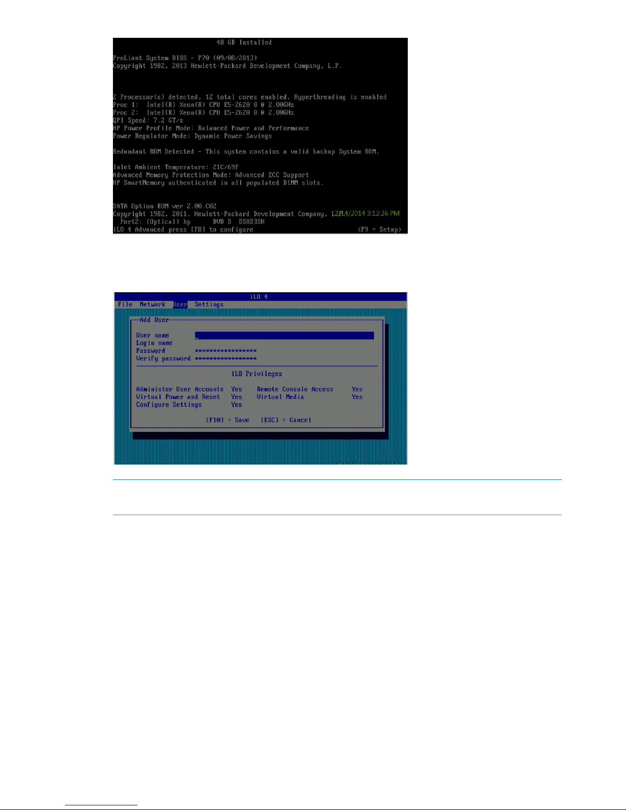
3. On the iLO screen, select User to add a user account.
4. Select User→New. The iLO Add User screen appears.
NOTE: The displayed iLO screen may vary slightly, depending on whether you are using a
Gen7 or Gen8 node.
5. Enter the following information in the listed iLO Add User screen fields:
• User Name: ibrixpwr
• Login Name: ibrixpwr
• Password: hpinvent
• Password Confirm: hpinvent
6. For Account Privileges, select Yes for all listed privileges.
7. Press F10.
8. Assign a fixed IP address, subnet mask address, and Gateway IP address for iLO. The iLO
Network Configuration screen appears.
56 Installing the HP StoreAll OS Software and configuring the HP StoreAll Storage system
Page 57

9. Press F10 to save network configurations and exit the application.
10. Repeat these steps for each HP StoreAll node.
NOTE: iLO creates a default, self-signed certificate for SSL connections, but it can result in an
"invalid certificate" error when accessing iLO web pages. You can safely ignore this error and
continue with the login process. If your environment requires the use of a valid certificate, see
"Administering SSL certificates" in the HP iLO 4 User Guide (available at: http://
h20628.www2.hp.com/km-ext/kmcsdirect/emr_na-c03334051-10.pdf) for information about
importing certificates.
Verifying LUNs and component firmware
Before you run the StoreAll Installation wizard, you must verify LUNs and component firmware.
Verifying LUNs
NOTE: You do not need to run the these verification commands on HP StoreAll 8200 or 9300
systems.
Verify volumes by entering the following command on one node in the couplet:
hpsp_spt -lv
Verify that the name of each LUN is unique. If not unique, run the following command on one node
in the couplet, which fixes the names:
hpsp_spt -fn
NOTE: You only need to run this command if you are assembling the hardware components on
site. If you have a complete factory-assembled rack, do not run this command.
Verifying component firmware
To ensure you are running the latest firmware:
1. Verify the firmware and save the output to a file for review verification later.
• Run this command on one node in each couplet:
hpsp_fmt -fr storage >/local/fwstorage.out
NOTE: You do not need to run hpsp_fmt -fr storage on HP StoreAll 8200 or
9300 systems.
• Run this command on the servers:
hpsp_fmt -fr server >/local/fwserver.out
Configuring initial and subsequent nodes on HP StoreAll 8xxx and 93xx Storage systems 57
Page 58

2. Create a hardware report. The hardware report will show status information about both servers
and storage.
• Run this command on every server/node, and if you run this on multiple servers, be sure
to create a unique file name each time:
hpspmonControl --server --filter text >/local/monsvr_x.out
Run this command to show the output on the screen:
more /local/monsvr.out
• Run this command on one node in a couplet:
hpspmonControl --storage --filter text >/local/storage_x.out
NOTE: You do not need to run this command on HP StoreAll 8200 systems.
Run this command to show the output on the screen:
more /local/storage.out
3. If you are connected to the VGA monitor and the keyboard, you can download the logs onto
a USB memory stick:
1. At the Linux prompt, enter startx. This will start a Gnome GUI interface.
2. Plug in the USB memory stick.
3. Drag and drop the log files from the /local/ folder to the USB memory stick.
Configuring nodes and a cluster on the HP StoreAll 8xxx and 93xx Storage system
This portion of the HP StoreAll OS Software installation process is completed using the StoreAll
Installation wizard and involves completing network configurations. The configuration process
involves:
• Setting the system name
• Setting the system date and time
• Configuring the network
• Entering a gateway IP address
• Confirming and then committing to configuration entries
Advanced network configuration options are also available when you use the wizard.
The installation wizard detects the network controller cards used and guides you through the
applicable steps for configuring the appropriate network for your hardware. The network
configuration that you create on the initial node can be used as the template for the other nodes.
NOTE: If you use Mode 4 networking, you must repeat the steps in this section on each node.
Perform the steps in this section to also set up networking for subsequent servers in your storage
system after completing the initial installation process on the initial server.
NOTE: At any time during this process, select Cancel or Quit (if available) to exit the application
or Back (if available) to go back to the previous screen. On applicable screens, press F1 to display
onscreen help information.
Use the Space bar and Tab key to move between screen options or move to available screen
buttons, such as Cancel, Ok, Back, and so forth.
If the screen goes into screen save mode, press the arrow key on the keyboard.
Before beginning this procedure, complete “Creating a bootable device and installing the HP
StoreAll OS Software” (page 51).
58 Installing the HP StoreAll OS Software and configuring the HP StoreAll Storage system
Page 59

To configure the initial server in your cluster, which is at the current HP StoreAll OS Software
version:
1. Log in to the initial node by entering root at the login prompt, and then enter hpinvent as
the password. If you have already completed these steps on the initial node, log in to the next
node, if necessary, and perform the steps in this section for subsequent nodes.
The StoreAll Installation — Welcome screen appears.
2. Select Begin to initiate the installation process. The Individual Server Setup screen appears.
3. Enter the host name in the Hostname field.
NOTE: The host name, which is the name of the local server, can include alphanumeric
characters and the hyphen (-) special character. It is a best practice to use only lowercase
characters in host names; uppercase characters can cause issues with HP StoreAll OS Software.
Do not use underscores (_) in the host name.
Configuring initial and subsequent nodes on HP StoreAll 8xxx and 93xx Storage systems 59
Page 60
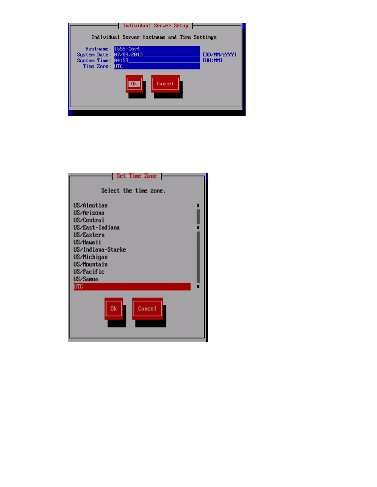
4. The system automatically detects the system time settings; however, if necessary, use the System
Date and System Time fields to update the time settings on the Individual Server Setup screen.
While setting the time zone, press Enter while the cursor is positioned in the Time Zone field
to display the list of time zones in a separate screen. Enter the first letter of your time zone,
or use the UP and DOWN arrow keys to find your time zone.
5. Select Ok to accept the screen time zone selection.
6. On the Network Configuration for HP StoreAll Data Access screen, select one of the following
options to configure the network for HP StoreAll data access, and then select Ok:
• Flat Networking (combined cluster/user network): Use this option to create a combined
cluster and user network. A single bonded interface (Bond0) is created using all available
NIC ports in node slots 5 and 6 for all network traffic. See flat and dual networking
information in “Before you begin configuring HP StoreAll 8xxx and 93xx Storage systems”
(page 55).
• Dual Networking (separate cluster and user network): Use this option to create separate
networks for cluster and user traffic. Two bonded interfaces (Bond0 and Bond1) are
60 Installing the HP StoreAll OS Software and configuring the HP StoreAll Storage system
Page 61
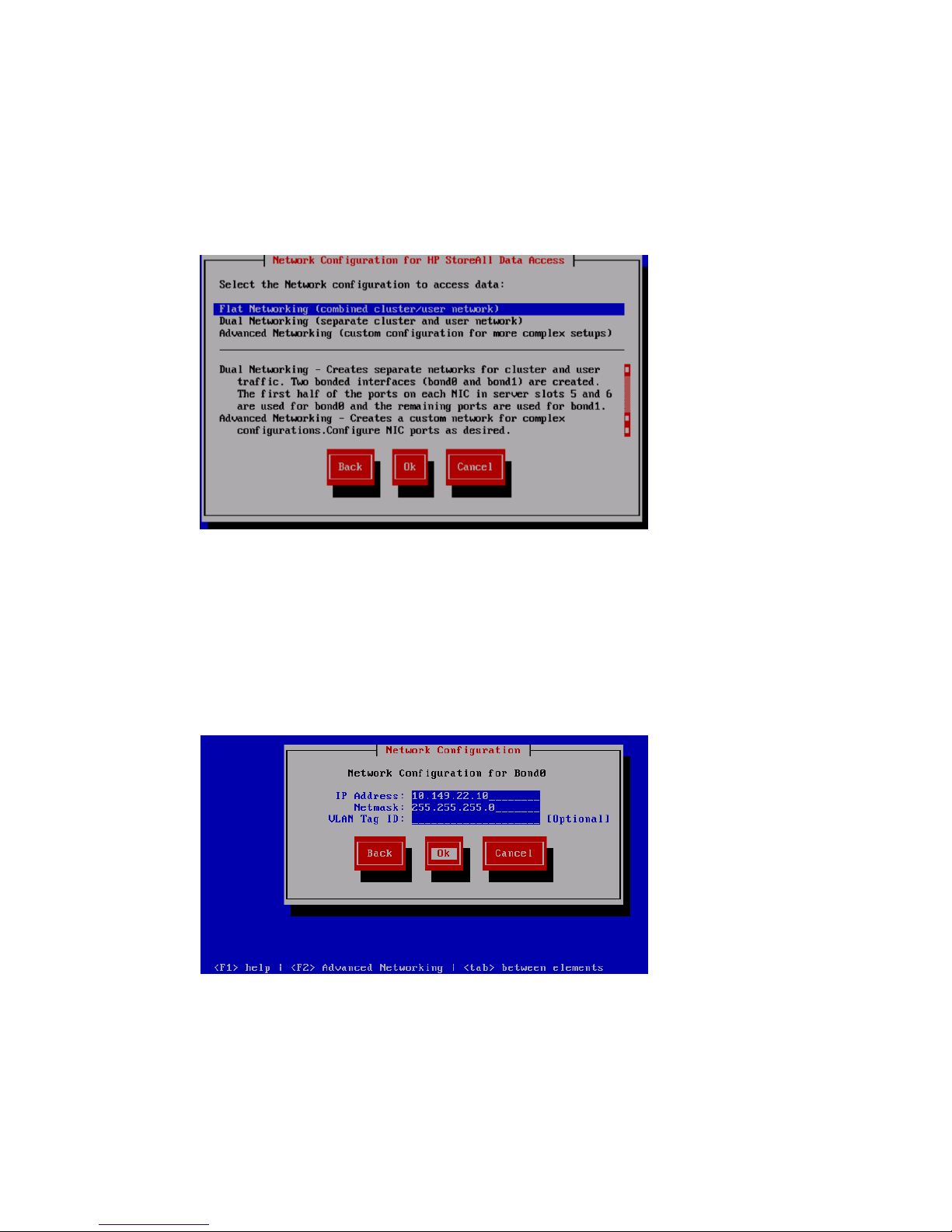
created. The first half of ports (right-side ports) on each NIC in node slots 5 and 6 are
used for Bond0, and the remaining ports (left side ports) are used for Bond1.
For the quad cards, the two ports on the right side of each slot/card is bond0. See flat
and dual networking information in “Before you begin configuring HP StoreAll 8xxx and
93xx Storage systems” (page 55).
• Advanced Networking (custom configuration for more complex setups): Use this option
to create a custom network for complex configurations. You may configure NIC ports, as
needed, with this option.
7. (For HP StoreAll 9320 and 9300 Storage systems only.) Do one of the following:
• If you selected Flat Networking (combined cluster/user network) or Dual Networking
(separate cluster and user network) in Step 6, then go to Step 8.
• If you selected Advanced Networking (customer configuration for more complex setups)
in Step 6, then go to Step 10.
8. (For HP StoreAll 9320 and 9300 Storage systems only.) Complete the Network Configuration
wizard screen(s):
• IP Address: The IP address is the address of the server on Bond0. For a single network
installation, this is the physical address of this node. For a multiple network installation,
this is the address of the blade on the management network.
• Netmask: The netmask (a 32-bit mask) divides an IP address into subnets and specifies
the available network hosts. This field is auto-filled with 255.255.0.0, but the netmask
entry may need to be modified, based on your specific network subnets.
Configuring initial and subsequent nodes on HP StoreAll 8xxx and 93xx Storage systems 61
Page 62

• VLAN Tag ID: VLAN capabilities provide hardware support for running multiple logical
networks over the same physical networking hardware. HP StoreAll supports the ability
to associate a VLAN tag with an FSN interface. For more information, see the HP StoreAll
OS Networking Best Practices Guide.
• F2 (function key): If you press F2, you can toggle between the default Network
Configuration screen and the Advanced Configuration screen. Use the Network
Configuration screen to change default parameters; and use the Advanced Configuration
screen to modify parameters, such as slaves, bond options, the network role of any bond,
and so forth.
If you press F2 to go to the Advanced Configuration screen, then go to Step 10.
9. (For HP StoreAll 8200 and 8800 Storage systems only.) Configure the network for iLO access:
a. Select one of the following options from the Network Configuration for iLO Access screen,
and then select Ok:
• Cluster Network—Choose this option if network routing allows the iLO ports on the
servers to be accessed from the cluster network.
• Separate iLO Network—Choose this option if the network used to access the server
iLO ports is separate and isolated from the cluster network. An additional network
(bond2) will be created. This network uses ports 0 and ports 1 on the system board.
b. After the User Info! screen automatically appears, review and note screen information.
• To accept default entries, select Ok and proceed to the next substep.
• To change default entries, select Ok, press F2, and then go to Step 11.
62 Installing the HP StoreAll OS Software and configuring the HP StoreAll Storage system
Page 63

NOTE: When the User Info! screen appears, the default bond mode displayed for 1
GbE Network Storage Gateway systems is Mode 6; however, HP recommends using
Mode4 instead. Be sure to access the Advanced Networking screen, and then change
the bond mode accordingly.
c. Review your selections on the Network Configuration wizard screen(s).
Table 15 (page 63) shows which Network Configuration wizard screen(s) automatically
display, based on selections that you made in Step 6 and Step 9.
Table 15 Network Configuration wizard completion requirements
Then you will be required to complete the
following Network Configuration
wizard(s)...
And if on the Network
Configuration for iLO
Access screen you
selected...
If on the Network
Configuration for HP
StoreAll Data Access screen
you selected...
Bond2Bond1Bond0
Separate
iLO
Network
Cluster
Network
Dual
Networking
Flat
Networking
√√√1.
√√√√2.
√√√√3.
√√√√√4.
An example Network Configuration wizard screen is shown in Figure 40 (page 63).
Depending on your selections on the Network Configuration for HP StoreAll Data Access
and Network Configuration for iLO Access screens, either Bond0, Bond1, or Bond2 is
indicated at the top of Network Configuration wizard screen(s).
Figure 40 Network Configuration for Bond0 screen
NOTE: You will be prompted to enter details for Bond1 after you enter details for Bond0.
d. Complete the Network Configuration screen(s):
• IP Address: The IP address is the address of the server on Bond0. For a single network
installation, this is the physical address of this node. For a multiple network installation,
this is the address of the blade on the management network.
• Netmask: The netmask (a 32-bit mask) divides an IP address into subnets and specifies
the available network hosts. This field is auto-filled with 255.255.0.0, but the
netmask entry may need to be modified, based on your specific network subnets.
Configuring initial and subsequent nodes on HP StoreAll 8xxx and 93xx Storage systems 63
Page 64

• VLAN Tag ID: VLAN capabilities provide hardware support for running multiple
logical networks over the same physical networking hardware. HP StoreAll supports
the ability to associate a VLAN tag with an FSN interface. For more information, see
the HP StoreAll OS Networking Best Practices Guide.
• F2 (function key): If you press F2, you can toggle between the default Network
Configuration screen and the Advanced Configuration screen.
e. Do one of the following:
• Select Ok to accept default entries that are currently displayed, and repeat Step 9.d
through Step 9.e for the next Network Configuration wizard screen. If there are no
additional Network Configuration wizard screens to be completed, go to Step 15.
• Press F2 to make advanced configuration changes (for example, bond device
changes), and then go to Step 10.
• Select Back to go back to the Network Configuration for iLO Access screen, update
the Network Configuration for iLO Access screen, and then go to Step 9. If you select
this option, any entries on the Network Configuration screen are not saved.
• Click Cancel to exit the installation process.
64 Installing the HP StoreAll OS Software and configuring the HP StoreAll Storage system
Page 65

10. If you pressed F2 (advanced networking) to change or update networking configurations:
a. Use the Up and Down arrow keys or tab to highlight one of the following options on the
Advanced Configuration screen:
• Add Bond Device: Adds a new bond device to the network configuration.
• Remove Bond Device: Removes an existing bond device from the network
configuration.
NOTE: Table 15 (page 63) lists the minimum bond requirements for dual and flat
networking selections. If you attempt to delete a bond device needed for the selected
dual or flat networking combination, the following warning screen appears.
If the Delete Confirmation! warning screen appears and you need to create a bond
device, select Yes to be automatically taken to the Advanced Configuration screen,
and recreate the needed bond device(s) for the needed network configuration.
Otherwise, select No.
• bondx: Unconfigured: Configures a bond device that has not yet been configured.
If more than one unconfigured device exists, those devices are also listed on the
Advanced Configuration screen.
• Press F2 to return to the Network Configuration screen, and then, for HP StoreAll
8200/8800 Storage systems, go to Step 9.e to complete the Network Configuration
screen(s); for HP StoreAll 9300/9320 Storage systems, go to Step 8. Any selections
made on the Advanced Configuration screen are disregarded.
b. Do one of the following:
• After selecting Add Bond Device, press Enter, and then go to the next step.
• After selecting bondx: Unconfigured, select Configure to make device configuration
changes, and then go to Step 9.e to complete the Network Configuration screen
requirements.
Configuring initial and subsequent nodes on HP StoreAll 8xxx and 93xx Storage systems 65
Page 66
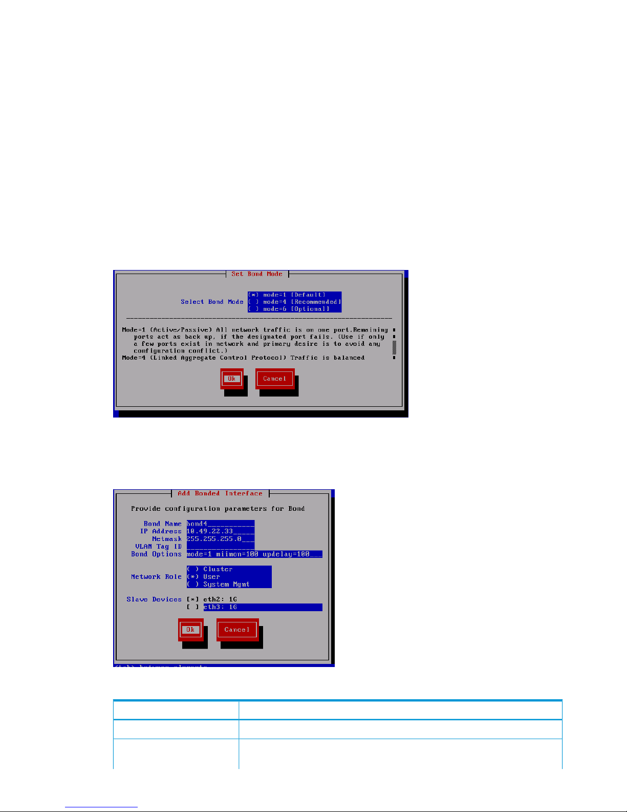
• Select Continue to skip the option to add, remove, or modify bond devices, and then
go to Step 15 to finalize configurations on the Configuration Summary screen.
• Select Back to return to the previous screen.
• Press F2 to complete single networking configurations.
11. If you selected Add Bond Interface in Step 10, select the appropriate bond mode on the Set
Bond Mode screen:
• Mode=1 (Default): Use this mode to direct all network traffic to one port. Remaining ports
act as a backup if the designated port fails. Use this option if only a few ports exist in
the network, and the primary intent is to avoid configuration conflicts.
• Mode=4 (Recommended): Use this option to balance network traffic across multiple ports.
To use this option, an Ethernet switch configuration is required.
• Mode=6 (Optional): Use this option to balance network traffic across all ports and cause
traffic to a given client to be directed to one port. This option is recommended if the switch
cannot be configured.
Click Ok, and then go to Step 12.
12. If you completed Step 11, wait for the Add Bond Interface screen to appear, and then fill out
the required fields.
Table 16 Field entry requirements for Add Bonded Interface screen
DescriptionField name
Enter the name for the bond device.Bond Name
Enter the server’s IP address. The IP address is the address of the server on Bond0.
For a single network installation, this is the physical address of this node. For a
IP Address
66 Installing the HP StoreAll OS Software and configuring the HP StoreAll Storage system
Page 67

Table 16 Field entry requirements for Add Bonded Interface screen (continued)
DescriptionField name
multiple network installation, this is the address of the blade on the management
network.
Enter the netmask IP address for the bond device being added. The netmask (a
32-bit mask) divides an IP address into subnets and specifies the available network
Netmask
hosts. This field is auto-filled with 255.255.0.0, but the netmask entry may
need to be modified, based on your specific network subnets.
Enter the VLAN tag ID. VLAN capabilities provide hardware support for running
multiple logical networks over the same physical networking hardware. HP StoreAll
VLAN Tag ID
supports the ability to associate a VLAN tag with an FSN interface. For more
information, see the HP StoreAll OS Networking Best Practices Guide.
The bond is configured with (and can operate with) default values or you can
use this field to set bond options (bond mode, mimon, and updelay mode). For
Bond Options
example, mode=1; mimon=100, and updelay=100. Use also any of the following
parameters:
• arp_interval
• arp_ip_target
• lacp_rate
• max_bonds
• primary
• use_carrier
• xmit_hash_policy
Identify whether the bond is part of a cluster or is a user or management-related
bond device.
Network Role
Select which Ethernet port is trunked to the bond device being created.Slave Devices
Select Ok to save entries and continue to the next step.
13. If you opted to complete advanced networking configurations prior to Step 10, Advanced
Network Configuration screens may automatically display. If this occurs, go back and complete
the Network Configuration screen or screens, as applicable to your storage platform, before
proceeding to the next step.
For instructions on completing Network Configuration screens, see instructions in Step 8 for
HP StoreAll 9300/9320 Storage systems or Step 9.d for HP StoreAll 8200/8800 Storage
systems.
14. On the Set Default Gateway screen, enter the default gateway IP address and then select Ok.
NOTE: If your default gateway is on a different subnet than Bond0, skip this field. A gateway
address is required to use the web UI.
Configuring initial and subsequent nodes on HP StoreAll 8xxx and 93xx Storage systems 67
Page 68
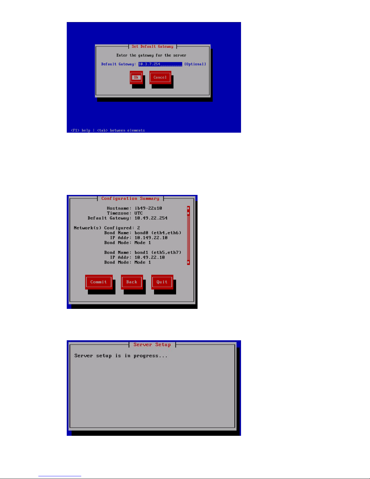
15. On the Configuration Summary screen, review displayed configurations and do one of the
following:
• Select Commit to save the displayed configurations and continue with the installation.
• If the configuration is incorrect or needs updating, select Back to return to the Network
Configuration screen. Complete Step 8 or Step 9.d.
If you select Commit, the setup wizard configures the node according to the information
entered. The Server Setup screen appears during the configuration process.
The X9000 Installation - Network Setup Complete screen appears.
68 Installing the HP StoreAll OS Software and configuring the HP StoreAll Storage system
Page 69

16. On the X9000 Installation - Network Setup Complete screen, select one of the cluster setup
methods, select Ok, and then go to the next applicable step.
IMPORTANT: To use the web UI, your cluster network must meet the following conditions:
• Network Bond0 was configured without errors.
• Broadcast is enabled. The web UI relies on broadcast network traffic.
• Broadcast or multicast functions are operational.
• You entered a gateway IP address on the Server Setup screen.
If your cluster does not meet these conditions, you must press F2 from the X9000 Installation
- Network Setup Complete screen to complete cluster networking in ASCII mode. See
“Completing the HP StoreAll 8xxx and 93xx server installation by configuring servers and a
cluster in ASCII mode” (page 72) to complete the installation.
• If you select Join this StoreAll server to an existing cluster, complete the following steps:
From the X9000 Installation Network Setup Complete screen, select Join this StoreAll
server to an existing cluster. The Join Cluster screen appears.
1.
Configuring initial and subsequent nodes on HP StoreAll 8xxx and 93xx Storage systems 69
Page 70

2. Do one of the following:
◦ If the management console is listed on the Join Cluster screen, select the desired
management console, and then select Ok.
◦ If the management console is not listed, select Cancel to display the Management
Console IP screen, enter the IP address of the management console, and then
select Ok.
3. The wizard registers and configures a passive management console (Fusion Manager)
on the server.
70 Installing the HP StoreAll OS Software and configuring the HP StoreAll Storage system
Page 71
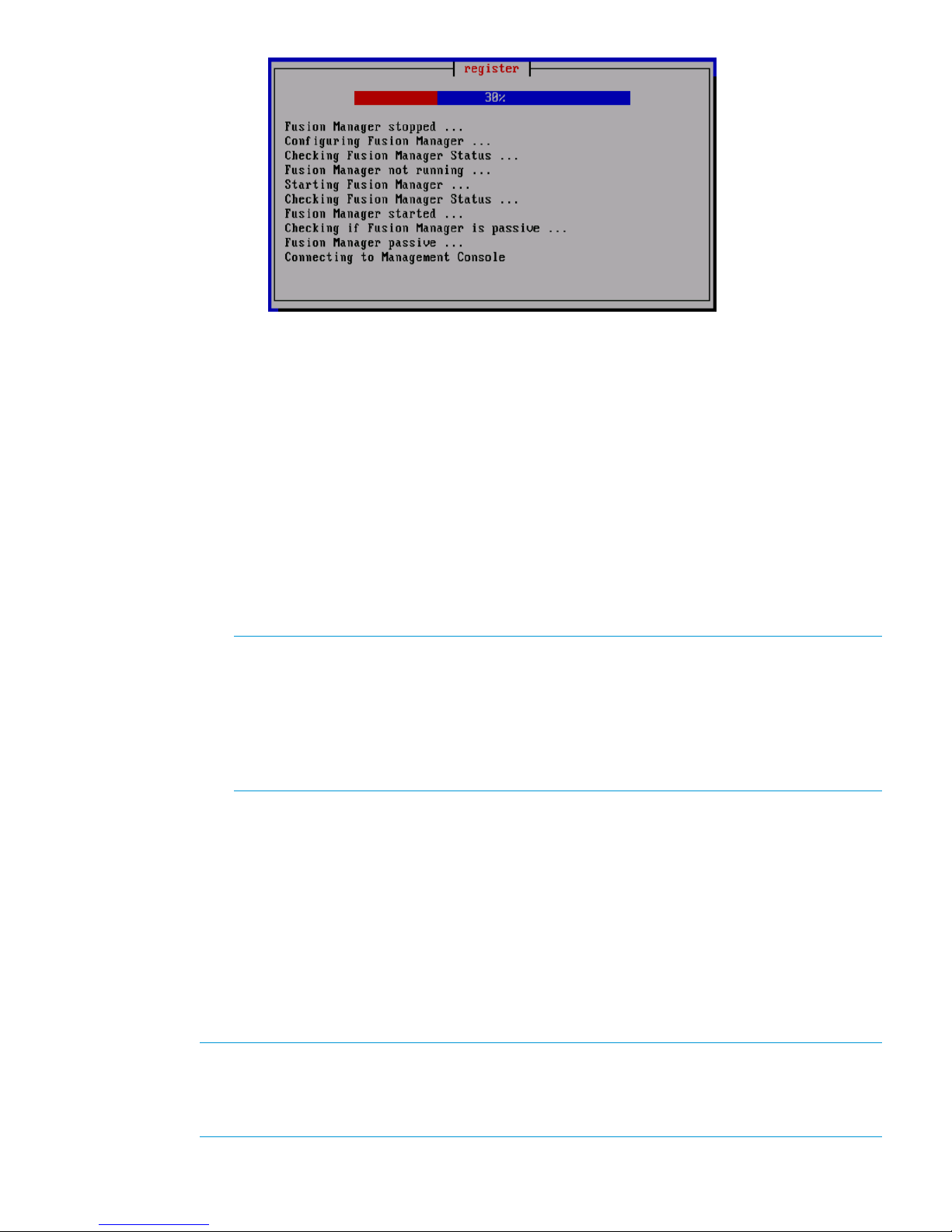
4. After the registry process completes, repeat the steps in Step 1 through this step to
add another node until all nodes in the storage system have been added. Once all
nodes have been added, continue to “Configuring clusters remotely with the Getting
Started Wizard” (page 105) to complete cluster configuration instructions, and then,
if applicable, go to “Discovering and configuring HP StoreAll servers and their
storage” (page 127).
• If you select Continue with cluster setup at this console (Local web UI session) or Continue
with cluster setup at this console (Remote web UI session), you can use the web to complete
network configuration details remotely or locally from the storage system. After a message
stating that the management console is to connect to the server appears, enter login
credentials when the subsequent HP StoreAll Management Console screen appears,
continue to “Configuring clusters remotely with the Getting Started Wizard” (page 105)
to complete cluster configuration instructions, and then, if applicable, go to “Discovering
and configuring HP StoreAll servers and their storage” (page 127).
NOTE: If you opt to continue using the console from which you are working by selecting
Continue with cluster setup at this console (Local web UI session), after the message stating
that the management console GUI is to be launched appears and a web page is
automatically opened, another message may display stating that the connection is an
untrusted one. If this occurs, select Add Exception, and then select Confirm Security
Exception. The login screen for the HP StoreAll Management Console appears. This
exception typically occurs with the Mozilla Firefox browser software application.
• If you select Exit Now (You just wanted to setup networking) and you are configuring a
subsequent server, rather than the initial server, the system is ready to be added to a
cluster. If necessary, continue to “Configuring clusters remotely with the Getting Started
Wizard” (page 105) to complete cluster configuration instructions, and then, if applicable,
go to “Discovering and configuring HP StoreAll servers and their storage” (page 127)
• If you select Exit Now (You just wanted to setup networking) and you are configuring the
initial server in the installation, to complete the entire installation process properly, you
must select Join this StoreAll server to an existing cluster to join the server to a cluster.
Otherwise, if you are configuring a subsequent server as part of the installation process,
rather than the initial server, the system is ready to be added to the cluster, if you opt to
do so.
NOTE: After you complete this step on the initial server in your storage system and select
one of the cluster options from the X9000 Installation - Network Setup Complete screen, you
will then be required to complete applicable follow-on steps to join the node to a cluster (as
instructed in this step) to properly complete the installation process.
Configuring initial and subsequent nodes on HP StoreAll 8xxx and 93xx Storage systems 71
Page 72

17. If you have completed the installation of the initial node and need to complete networking for
subsequent servers, go to Step 1.
18. Determine whether there are any HP StoreAll OS Software maintenance releases later than
the current HP StoreAll OS Software version (see “Factory default and current HP StoreAll OS
Software version information” (page 7)). If maintenance releases are available, acquire
necessary files and follow provided maintenance release instructions.
Completing the HP StoreAll 8xxx and 93xx server installation by configuring servers
and a cluster in ASCII mode
Use the procedures in this section if, on the X9000 Installation - Network Setup Complete screen
in Step 16:
• You selected F2 from the X9000 Installation—Network Setup Complete screen.
• You were unable to select the Continue with cluster setup remotely (Remote web UI session)
option.
• You were unable to select the Continue with cluster setup at this console (Local web UI session)
option.
To configure the initial server:
NOTE: At any time during this procedure, you may select Cancel to cancel the installation or
Back (if available) to go back to the previous screen.
Use the Space bar and Tab key to move between screen options or move to available screen
buttons, such as Cancel, Ok, Back, and so forth.
1. On the Form a Cluster — Step 2 screen, enter a name for the cluster, and specify the IP address
and netmask for the Management Console IP (also called the Cluster Management IP). This a
virtual IP address (VIF) assigned to the entire cluster for management use. Think of the address
as the IP address of the cluster. Connect to this VIF in future GUI management sessions. The
VIF remains highly available.
2. Enter the IP addresses and domain name for your DNS servers, as well as the IP addresses
for your NTP servers, and then select Ok.
3. On the Configuration Summary screen, review the configuration that you specified, and then
select Commit.
72 Installing the HP StoreAll OS Software and configuring the HP StoreAll Storage system
Page 73
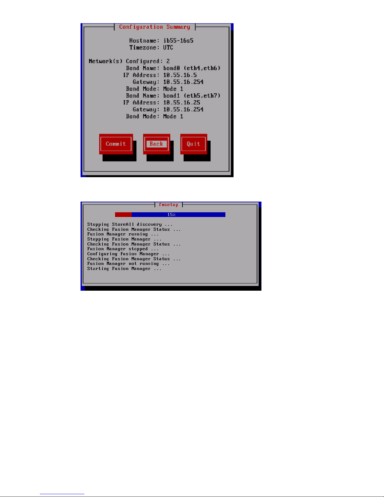
The wizard configures the active management console (Fusion Manager) on the server.
4. If Bond0 or cluster network is not routed and the Bond1 or user network is routed, define the
default gateway for Bond1:
a. Set the default gateway in /etc/sysconfig/network.
b. Add a default route for Bond1:
ibrix_nic -r -n IFNAME -h HOSTNAME -A -R ROUTE
For example:
# ibrix_nic -r -n bond1 -h ibrix02a -A -R 10.10.125.1
5. Optional: If you want to be able to access the Fusion Manager through the Bond1/user
network, create a management VIF for Bond1:
ibrix_fm -c <VIF IP address> -d <VIF device> -n <VIF netmask> -v
<VIF type>
For example:
# ibrix_fm -c 10.10.125.101 -d bond1:1 -n 255.255.255.0 -v user
6. To add additional servers (if any), go to Step 1.
The installation is complete on the initial node. To complete installation procedures, continue to
“Configuring clusters remotely with the Getting Started Wizard” (page 105).
Configuring initial and subsequent nodes on HP StoreAll 8xxx and 93xx Storage systems 73
Page 74

Configuring the HP StoreAll 9730 Storage systems
This section provides instructions for configuring the HP StoreAll 9730 Storage system.
IMPORTANT: These installation instructions are intended for use with only those HP StoreAll
Storage systems that have never been configured and are installed with the current HP StoreAll
OS Software version of the HP StoreAll OS Software (see “Factory default and current HP StoreAll
OS Software version information” (page 7)). If you already have a configured system and are
upgrading your version of the HP StoreAll OS Software, see the HP StoreAll OS Upgrade Guide
for upgrade instructions (for the applicable version).
If at any time during this portion of the installation process you experience any issues, see
“Troubleshooting HP StoreAll 9730 Storage system installation issues” (page 101) for solutions to
common installation issues.
Before you begin configuring HP StoreAll 9730 Storage systems
Before beginning HP StoreAll 9730 Storage system configuration procedures:
• Review “HP StoreAll 9730 hardware configuration information” (page 74).
• Review “Configuring HP StoreAll 9730 nodes with iLO” (page 75)
• Review “Verifying LUNs and component firmware” (page 76).
• Make sure that the AD server and the NTP server are synchronized with the same time, and
that the AD server and the HP StoreAll cluster are configured to synchronize the time from the
same NTP server. During the installation process, you will be prompted to configure an NTP
server for time synchronization. However, after a cluster node is joined to a service, the cluster
attempts to synchronize the time with the AD server. If the NTP and AD servers are not
synchronized, this issue causes the cluster nodes to receive conflicting time updates, which
can lead to errors, such as file system creation failures.
• Know the required IP addresses, as specified in “IP address requirements for flat (unified)
networks” (page 27).
• Know the administrator passwords for OA and VC. The default passwords are on the labels
affixed to the back of the chassis.
• Ensure that port 69 (tftp) is open before starting the installation.
• If you are performing configuration procedures on an existing cluster, ensure that the same
version of the HP StoreAll OS Software is installed on all nodes.
HP StoreAll 9730 hardware configuration information
The HP StoreAll 9730 Storage system is configured at the factory as follows:
• The factory default version of the HP StoreAll OS Software is installed on the nodes (see
“Factory default and current HP StoreAll OS Software version information” (page 7)) version
information for the HP StoreAll 9730 Storage system.
• LUNs are created and preformatted on the 9730 CX storage system.
• Depending on the system size, the HP StoreAll 9730 Storage system is partially or totally
pre-racked and cabled.
74 Installing the HP StoreAll OS Software and configuring the HP StoreAll Storage system
Page 75

NOTE: Four transit brackets are installed in the rack for stability during shipping (one bracket
in each corner of the rack). The transit brackets can remain in place or be removed after the
HP StoreAll 9730 Storage system installed. One of the brackets covers the power supply so
if the power supply needs to be serviced, the transit bracket will have to be removed. For
more information about the transit brackets, see the HP Intelligent Rack Family User Guide:
http://bizsupport1.austin.hp.com/bc/docs/support/SupportManual/c03209373/
c03209373.pdf
Configuring HP StoreAll 9730 nodes with iLO
Before configuring your HP StoreAll Storage system, you must configure the nodes with iLO.
To set up iLO on the HP StoreAll node, create an iLO account on each HP StoreAll node (server)
that is to be part of the installed cluster:
1. Using the keyboard, video, mouse (KVM), connect to the initial HP StoreAll node.
2. Power on or reset (Cntrl-Alt-Del) the node, and watch the boot messages. After the boot
message, (iLO 4 Advanced press [F8] to configure) appears, press F8.
3. On the iLO screen, select User→New. The iLO Add User screen appears.
4. Enter the following information on the iLO Add User screen:
• User Name: ibrixpwr
• Login Name: ibrixpwr
Configuring the HP StoreAll 9730 Storage systems 75
Page 76

• Password: hpinvent
• Password Confirm: hpinvent
5. For Account Privileges, select Yes for all listed privileges.
6. Press F10.
7. Repeat these steps for each HP StoreAll node.
NOTE: iLO creates a default, self-signed certificate for SSL connections, but it can result in an
"invalid certificate" error when accessing iLO web pages. You can safely ignore this error and
continue with the login process. If your environment requires the use of a valid certificate, see
"Administering SSL certificates" in the HP iLO 4 User Guide (available at http://
h20628.www2.hp.com/km-ext/kmcsdirect/emr_na-c03334051-10.pdf) for information about
importing certificates.
Verifying LUNs and component firmware
Before your run the StoreAll Installation wizard, you must verify LUNs and component firmware.
Verifying LUNs
Verify volumes by entering the following command on one node in the couplet:
hpsp_spt -lv
Verify that the name of each LUN is unique. If not unique, run the following command on one node
in the couplet, which fixes the names:
hpsp_spt -fn
NOTE: You only need to run this command if you are assembling the hardware components on
site. If you have a complete factory-assembled rack, do not run this command.
Verifying component firmware
To ensure you are running the latest firmware:
1. Verify the firmware and save the output to a file for review verification later.
• Run this command on one node in each couplet:
hpsp_fmt -fr storage >/local/fwstorage.out
NOTE: You do not need to run hpsp_fmt -fr storage on HP StoreAll 8200 systems.
• Run this command on the servers:
hpsp_fmt -fr server >/local/fwserver.out
2. Create a hardware report. The hardware report will show status information about both servers
and storage.
• Run this command on every server/node, and if you run this on multiple servers, be sure
to create a unique file name each time:
hpspmonControl --server --filter text >/local/monsvr_x.out
Run this command to show the output on the screen:
more /local/monsvr.out
• Run this command on one node in a couplet:
hpspmonControl --storage --filter text >/local/storage_x.out
Run this command to show the output on the screen:
76 Installing the HP StoreAll OS Software and configuring the HP StoreAll Storage system
Page 77

more /local/storage.out
• Run this command on the chassis:
hpspmonControl --chassis --filter text >/local/chassis_x.out
Run this command to show the output on the screen:
more /local/chassis.out
3. If you are connected to the VGA monitor and the keyboard, you can download the logs onto
a USB memory stick:
a. At the Linux prompt, enter startx. This will start a Gnome GUI interface.
b. Plug in the USB memory stick.
c. Drag and drop the log files from the /local/ folder to the USB memory stick.
Configuring OA1 IP addresses for the Onboard Administrator
Complete the following steps to configure OA1 IP addresses for the Onboard Administrator. At
any time during this configuration process, press Cancel to cancel the procedure, or press Help to
acquire onscreen help information.
1. Access the Insight Display, which is located on the front of the HP StoreAll storage system.
2. From the Main Menu of the Insight Display, navigate to Enclosure Settings, and press OK.
3. On the Enclosure Settings screen, select Active OA, and press OK.
4. On the Network Settings: OA1 Active screen, select Network Properties, and press OK.
Configuring the HP StoreAll 9730 Storage systems 77
Page 78
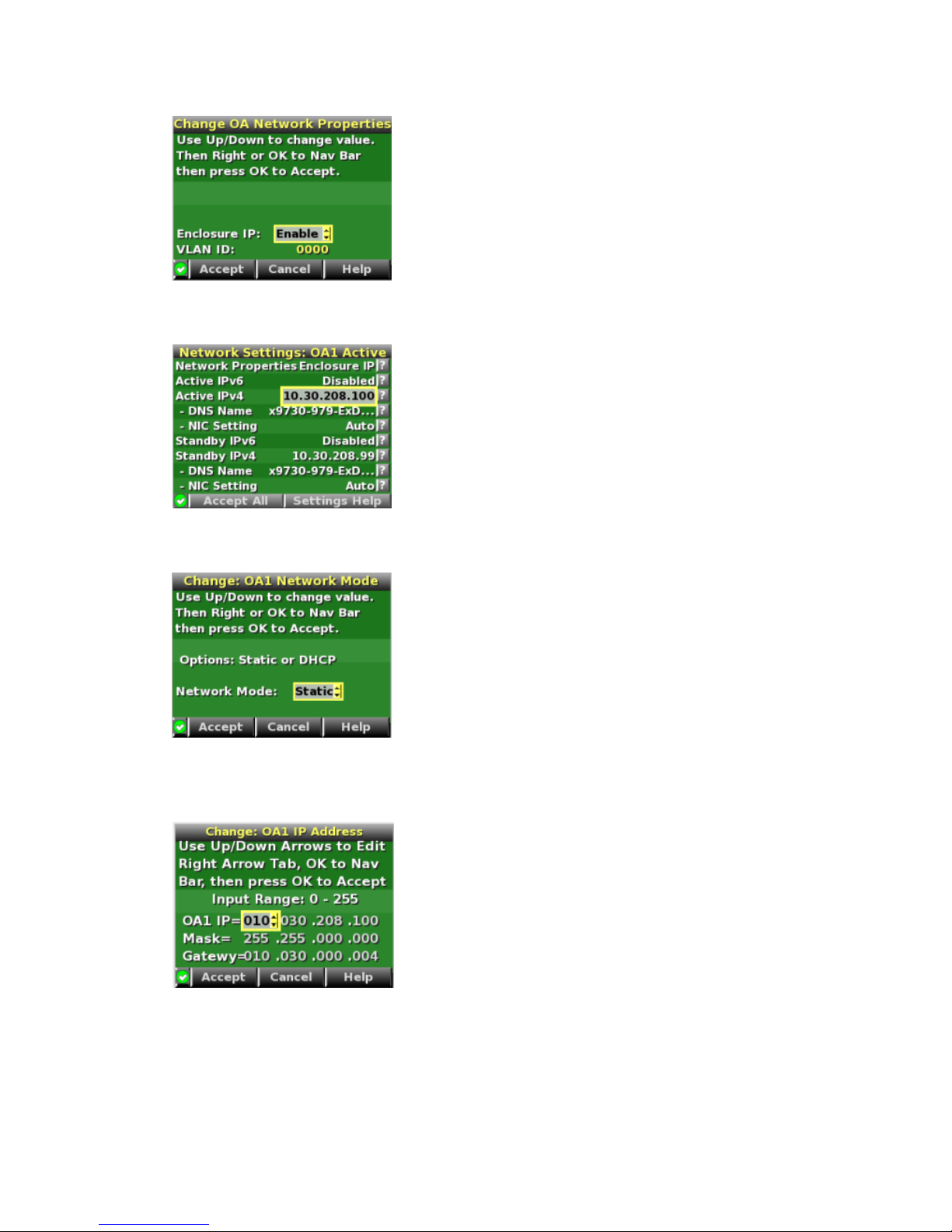
5. On the Change OA Network Properties screen, set Enclosure IP to Enable, and press OK to
accept.
6. On the Network Settings:OA1 Active screen, navigate to Active IPv4, and press OK.
7. On the Change:OA1 Network Mode screen, change DHCP to Static, and press OK to accept.
8. On the Change: OA1 IP Address screen, set the IP address, subnet mask, and gateway
(optional), and accept the changes.
9. On the Network Settings: OA1 Active screen, select Accept All, and press OK.
78 Installing the HP StoreAll OS Software and configuring the HP StoreAll Storage system
Page 79

10. On the Enclosure Settings screen, select Standby OA or OA2, and press OK.
11. On the Network Settings:OA2 screen, navigate to Active IPv4, and press OK.
12. Set the IP address, subnet mask, and gateway (optional), and accept the changes.
13. Go back to the Network Settings:OA2 screen, navigate to Accept All, and press OK.
The Main Menu reappears and the procedure is complete.
Configuring the chassis on the HP StoreAll 9730 Storage system
This portion of the HP StoreAll OS Software installation process is completed using a wizard
application and involves completing network configurations. The configuration process, which uses
the X9730 Setup Wizard, involves:
• Setting the system name
• Setting the system date and time
• Configuring the network
• Entering a gateway IP address
• Confirming and then committing to, configuration entries
Advanced network configuration options are also available when you use the wizard.
NOTE: At any time during this process, select Cancel or Quit (if available) to exit the application
or Back (if available) to go back to the previous screen. On applicable screens, press F1 to display
on-screen help information.
Use the Space bar and Tab key to move between screen options or move to available screen
buttons, such as Cancel, Ok, Back, and so forth.
If the screen goes into screen save mode, press the arrow key on the keyboard.
Before beginning this procedure, complete the instructions in “Creating a bootable device and
installing the HP StoreAll OS Software” (page 51).
To start the X9730 Setup Wizard:
Configuring the HP StoreAll 9730 Storage systems 79
Page 80

Procedure 2
80 Installing the HP StoreAll OS Software and configuring the HP StoreAll Storage system
Page 81
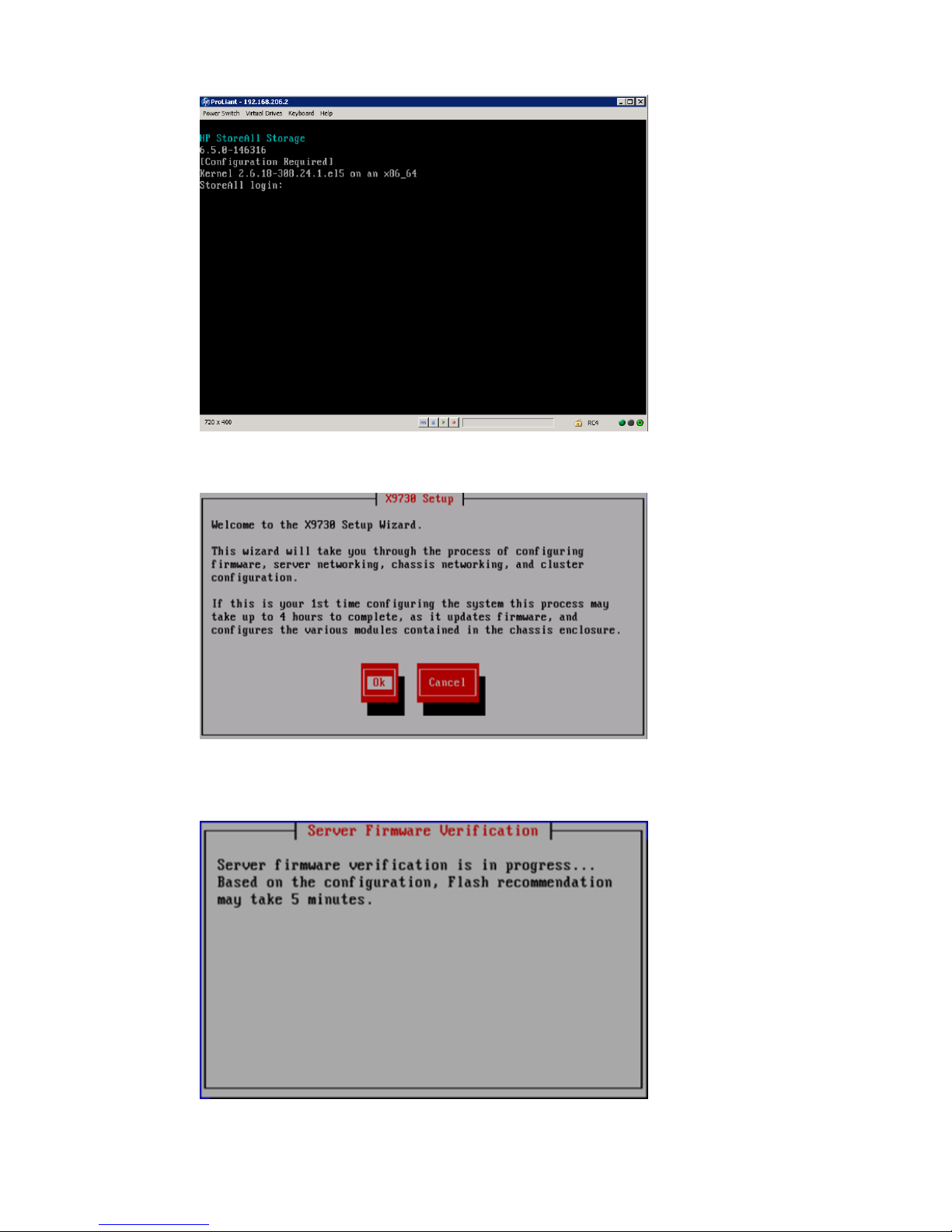
1. Log in to blade 1.
The X9730 Setup screen appears. Click Ok.
The setup wizard verifies the firmware on the system and notifies you if a firmware update is
needed.
Configuring the HP StoreAll 9730 Storage systems 81
Page 82
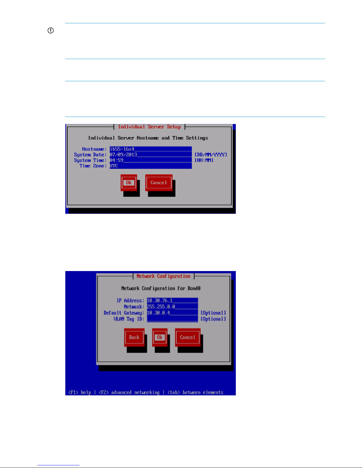
IMPORTANT: HP recommends that you update node firmware before continuing with the
installation. HP StoreAll 9730 Storage systems have been tested with specific node firmware
versions. Continuing the installation without upgrading to a supported firmware version can
result in a defective system.
2. Provide the host name (blade name) on the Individual Server Setup screen. The installation
detects the time settings.
NOTE: The host name, which is the name of the local server, can include alphanumeric
characters and the hyphen (-) special character. It is a best practice to use only lowercase
characters in host names; uppercase characters can cause issues with HP StoreAll OS Software.
Do not use an underscore (_) in the host name.
3. If needed, update the time settings on the Individual Server Setup screen. While setting the
time zone, press Enter while the cursor is positioned in the Time Zone field to display the list
of time zones in a separate screen. Enter the first letter of your time zone, or use the UP and
DOWN arrow keys to find your time zone. Select Ok to accept screen selections.
On the Network Configuration screen, the system defines the server on Bond0.
4. Complete the Network Configuration screen(s):
• Hostname: The host name (in the example, Bond0) can include alphanumeric characters
and the hyphen (–) special character. It is a best practice to use a host name with only
82 Installing the HP StoreAll OS Software and configuring the HP StoreAll Storage system
Page 83
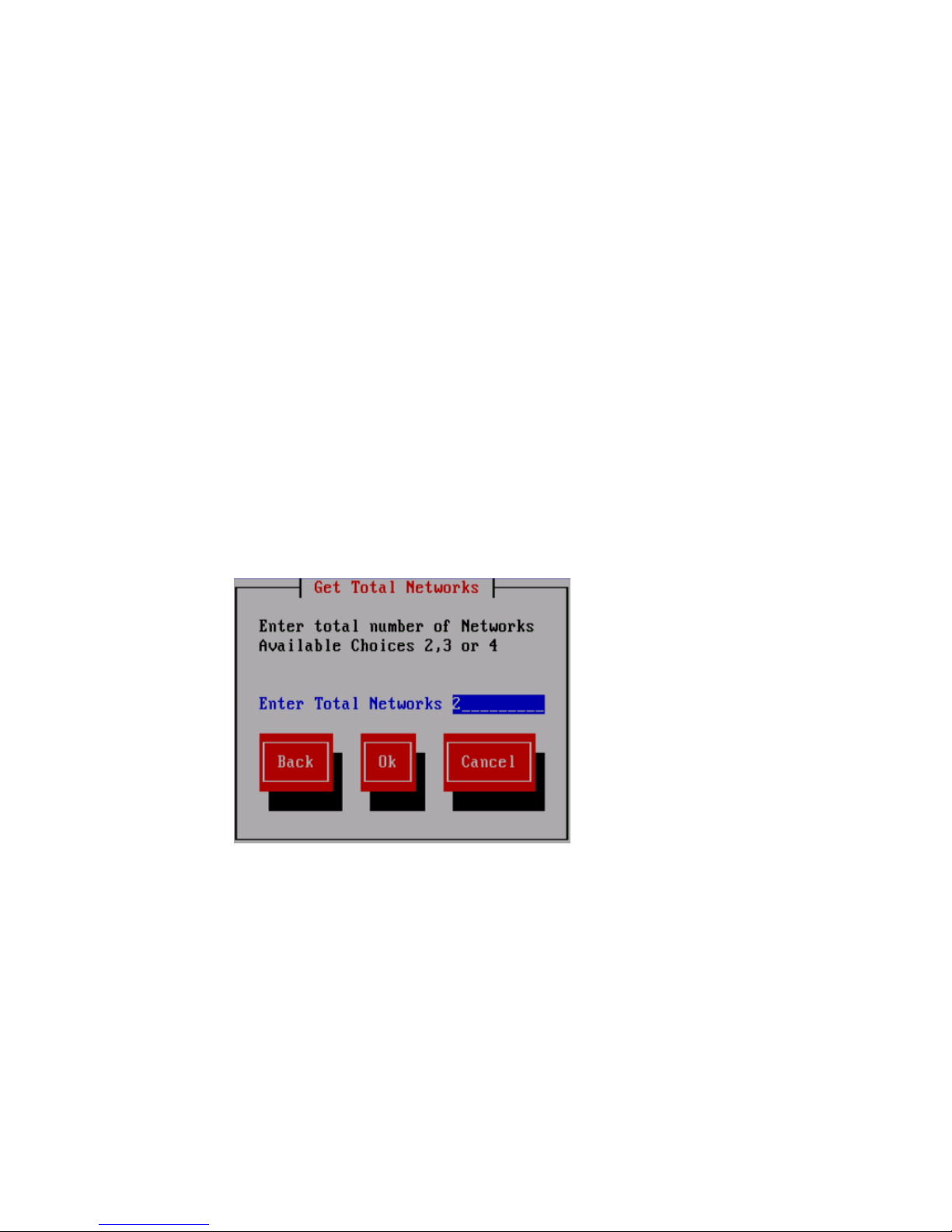
lowercase characters; uppercase characters can cause issues with HP StoreAll Storage
system software. Do not use an underscore (_) in the host name.
• IP Address: The IP address is the address of the server on Bond0.
• Netmask: The netmask (a 32-bit mask) divides an IP address into subnets and specifies
the available network hosts. This field is auto-filled with 255.255.0.0, but the netmask
entry may need to be modified, based on your specific network subnets.
• Default Gateway: The default gateway provides a route between networks. If your default
gateway is on a different subnet than Bond0, skip this field.
Later in this procedure, you can select either web UI or ASCII mode to complete the
installation. A gateway address is required to use the web UI.
• VLAN Tag ID: VLAN capabilities provide hardware support for running multiple logical
networks over the same physical networking hardware. HP StoreAll supports the ability
to associate a VLAN tag with an FSN interface. For more information, see the HP StoreAll
Storage Network Best Practices Guide.
• F2 (function key): If you press F2, you can toggle between the default Network
Configuration screen and the Get Network Totals and Advanced Configuration screens.
Use the Advanced Configuration screen to change default parameters; and specify the
number of networks and modify parameters, such as slaves, bond options, the network
role of any bond, and so forth.
5. To change network configuration default parameters, press F2, and then, on the Get Total
Networks screen:
a. In the Enter Total Networks field, enter the number of networks.
b. Select Ok to continue to the Advanced Configuration screen to complete network
configuration changes.
Configuring the HP StoreAll 9730 Storage systems 83
Page 84

6. Make advanced network configuration changes:
a. On the Advanced Configuration screen, select an interface option. Available options are:
• Add Bond Device: Adds a new bond device to the network configuration.
• Remove Bond Device: Removes an existing bond from the network configuration.
• bondx: Unconfigured: Configures a bond device that has not yet been configured.
If more than one unconfigured device exists, those devices are also listed on the
Advanced Configuration screen.
NOTE: You may press F2 from the Advanced Configuration screen to return to the
Network Configuration screen. This action cancels entries made on this Advanced
Configuration screen.
b. Do one of the following:
• Select Continue to save interface selection change, and then go to Step 9.
• Select Configure to configure the selected interface. If you select Configure, the Edit
Bonded Interface screen appears.
c. If you opted to configure the interface, complete the fields listed on the Edit Bonded
Interface screen, and then click Ok.
84 Installing the HP StoreAll OS Software and configuring the HP StoreAll Storage system
Page 85

The fields on the Edit Bonded Interface screen are:
• Bond Name: The host name (in the preceding example, Bond0) can include
alphanumeric characters and the hyphen (–) special character. It is a best practice
to use a host name with only lowercase characters; uppercase characters can cause
issues with HP StoreAll Storage system software. Do not use an underscore (_) in the
host name.
• IP Address: Enter the IP address of the server on Bond0.
• Netmask: The netmask (a 32-bit mask) divides an IP address into subnets and specifies
the available network hosts. This field is auto-filled with 255.255.0.0, but the
netmask entry may need to be modified, based on your specific network subnets.
• Bond Options: The bond is configured with (and can operate with) default values or
you can use this field to set bond options (bond mode, mimon, and updelay mode).
For example, mode=1; mimon=100, and updelay=100. Use also any of the following
parameters:
◦ arp_interval
◦ arp_ip_target
◦ lacp_rate
◦ max_bonds
◦ primary
◦ use_carrier
◦ xmit_hash_policy
• Network Role: Use the field to determine whether the bond is part of a cluster or is
a user or management-related bond device.
• Slave Device: Use this field to select which Ethernet port is trunked to the bond device
being created.
NOTE: The number of bonds and the slaves for those bonds are predefined, based on
the number of networks chosen. As such, different slave devices cannot be selected.
7. On the Configuration Summary screen, review configuration details, and then select Commit.
Configuring the HP StoreAll 9730 Storage systems 85
Page 86

After selecting Commit, the wizard sets up the blade, based on the information entered.
8. The setup wizard configures the chassis on the HP StoreAll 9730 Storage system. See the HP
StoreAll Storage Network Best Practices Guide for detailed information about chassis
components. (This step fails if the OA IP address has not been set up or if the blade cannot
communicate with the OA.) The Active Virtual Connect is, by default, the Virtual Connect in
interconnect bay 1. If the system is at factory defaults, the administrator passwords for OA
and Virtual Connect are shown on labels affixed to the back of the chassis. If passwords were
reset, enter the new passwords.
IMPORTANT: If you are using the default flat network layout, select Ok on the Confirming
Onboard Administrator and Virtual Connect Settings screen, and go to Step 9.
9. The wizard validates the information you entered. The following tests are performed during
the validation process:
• Pings the active OA
• Verifies the OA password
• Verifies that OA at that IP address is the active OA
• Verifies the OA firmware.
86 Installing the HP StoreAll OS Software and configuring the HP StoreAll Storage system
Page 87

If any of these tests fail, verify the configuration of the OA and VC modules as described on
the failure report displayed on the GUI. If you need to re-enter the IP address for the OA, select
Back to return to the Confirming Onboard Administrator and Virtual Connect Settings screen,
where you can make your changes.
NOTE: If the initialization of the credential manager fails, the GUI displays a message asking
you to initialize the credential manager manually. See “Credential Manager initialization
failed” (page 103) for more information.
10. Set the iLO IP addresses. On the Get iLO IP Addresses screen, select the method that you want
to use to set up iLO IP addresses. Use the space bar to select or clear the check boxes.
• To configure the iLO IP addresses in sequence, enter the first iLO IP address on the Set
iLO IP Addresses screen. For example, if 172.16.3.1 is the starting iLO IP address, the
installer sets the iLO IP addresses in the range 172.16.3.1 to 172.16.3.16 by
incrementing 1 to the last octet of the IP address.
• To configure the iLO IP addresses manually, enter each iLO IP address on the Enter iLO
IP Addresses screen.
Configuring the HP StoreAll 9730 Storage systems 87
Page 88

11. Note the listed IP addresses on the Confirm iLO IP Addresses screen and select Ok to continue.
12. Configure the chassis interconnect bays (VCs and SAS switches) by specifying whether you
want to configure the Interconnect (IC) IP addresses in sequence or manually from the Get
Interconnect IP Addresses screen. Use the space bar to make a selection, and then select Ok.
13. Do one of the following:
• Configure the Interconnect (IC) IP addresses in sequence by entering the first Interconnect
(IC) IP address on the Set Interconnect IP Addresses screen, and then select Ok. The
installer then sets the remainder of the addresses sequentially for all 8 interconnect bays.
For example, if 172.16.3.21 is the starting Interconnect (IC) IP Address, the installer sets
the Interconnect (IC) IP Addresses in the range 172.16.3.21–172.16.3.28.
88 Installing the HP StoreAll OS Software and configuring the HP StoreAll Storage system
Page 89

• Configure the Interconnect IP addresses manually by entering each address on the Set
Interconnect IP Addresses screen, and then select Ok.
14. The wizard then lists the IP addresses specified on the Confirm IC IP Addresses screen, and
then select Ok to continue.
15. Enter the DNS and NTP server information used by the Onboard Administrator.
Afterwards, the wizard configures the OA. This process takes up to 45 minutes to complete.
The wizard verifies the VC configuration and creates a new user called hpspAdmin.
Configuring the HP StoreAll 9730 Storage systems 89
Page 90

16. If required, provide the needed input when the following events occur:
• The wizard attempts to log in to the Virtual Connect manager using the Administrator
password that you supplied earlier. If the attempt fails, you can retry the attempt or re-enter
the password. (Retry is helpful only if a timeout caused the VC password check to fail.)
• When the wizard can log in to the VC manager successfully, it verifies the VC firmware
and asks you to update it, if necessary.
• When the firmware is at the correct level, the wizard verifies that the VC is in a default
state.
• The wizard configures the VC. The setup process first powers down blades 2-16, and
then powers down blade 1. On blade 1, the power remains off for approximately 3
minutes. Blade 1 then reboots twice.
17. Log in to blade1 again after the Linux login prompt appears.
The wizard makes the following checks:
• Pings the VC management IP address
• Verifies the hpspAdmin account created earlier
NOTE: If a check fails, take the corrective actions described on the GUI.
90 Installing the HP StoreAll OS Software and configuring the HP StoreAll Storage system
Page 91
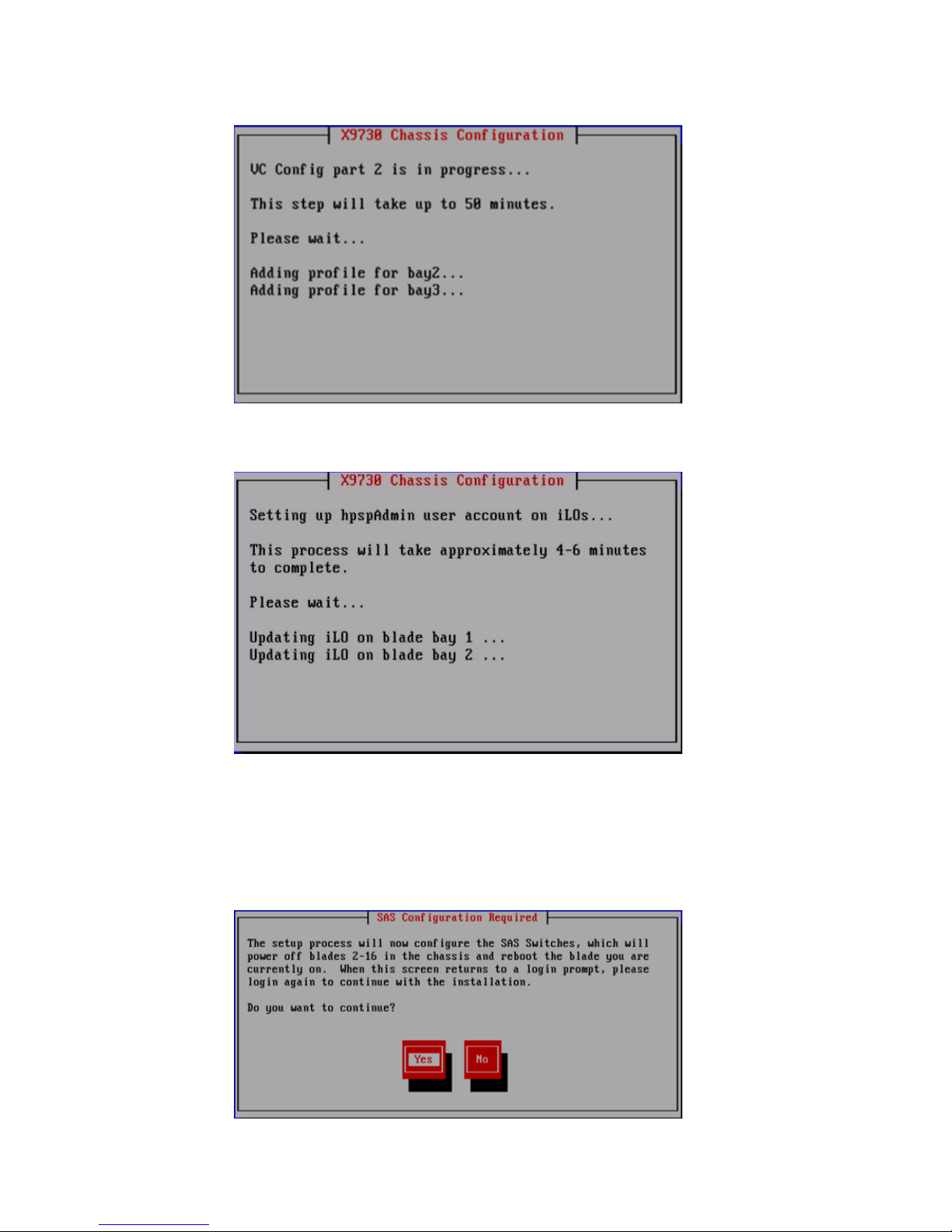
18. Note the following actions performed by the wizard:
• Configures the remaining bays for the Virtual Connect modules in the chassis.
• Verifies the VC configuration and then creates an hpspAdmin user account on each iLO.
• Validates the VC configuration and verifies the SAS firmware. If necessary, the SAS
switches are flashed with the correct firmware.
• Verifies the SAS configuration. After determining the correct layout of the storage
hardware, the wizard configures the SAS switch zoning so that couplets see the same
storage.
Configuring the HP StoreAll 9730 Storage systems 91
Page 92
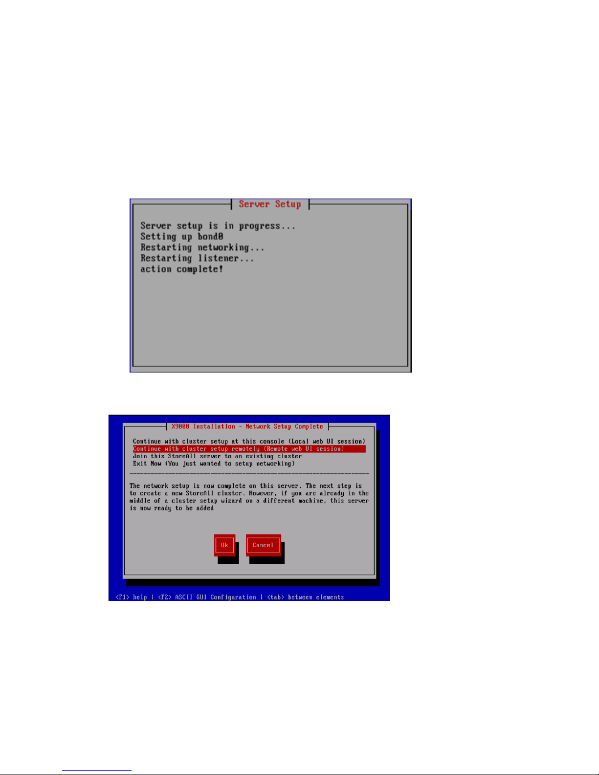
• Powers off blades 2–16, applies the SAS configuration, and then reboots blade 1. Log
in to blade 1 when the Linux login prompt appears.
• The wizard takes the following actions:
Verifies the SAS configuration to ensure that SAS zoning is set up correctly◦
◦ Powers on blades 2–16
◦ Verifies storage firmware to ensure that is set up correctly
◦ Validates the LUN layout and configures it if necessary
• Forms Bond0 from eth0 and eth3.
The X9000 Installation - Network Setup Complete screen appears.
19. On the X9000 Installation - Network Setup Complete screen, select Ok, and then select one
of the following cluster setup methods:.
92 Installing the HP StoreAll OS Software and configuring the HP StoreAll Storage system
Page 93

IMPORTANT: To use the web UI, your cluster network must meet the following conditions:
• Network Bond0 was configured without errors.
• Broadcast is enabled. The web UI relies on broadcast network traffic.
• Broadcast or multicast functions are operational.
• You entered a gateway IP address on the Server Setup screen.
If your cluster does not meet these conditions, you must press F2 from the X9000 Installation
- Network Setup Complete screen to complete cluster networking in ASCII mode. See “Creating
a cluster using ASCII mode on blade 1 on the HP StoreAll 9730 Storage system” (page 93)
for related procedures to complete the installation.
NOTE: After you complete this step on the initial server in your storage system and select
one of the cluster options from the X9000 Installation - Network Setup Complete screen options,
you will then be required to complete applicable follow-on steps to complete the installation
process.
• If you select Join this StoreAll server to an existing cluster, continue to “Installing additional
HP StoreAll 9730 Storage system blades” (page 95). During a remote console session,
a message appears instructing you to go to Fusion Manager to complete the installation
process.
• If you select Continue with cluster setup at this console (Local web UI session) or Continue
with cluster setup at this console (Remote web UI session), after a message stating that
the management console is to connect to the server is displayed, continue to “Configuring
clusters remotely with the Getting Started Wizard” (page 105) and enter login credentials
on the subsequent HP StoreAll Management Console screen.
NOTE: If you opt to continue using the console from which you are working by selecting
Continue with cluster setup at this console (Local web UI session), after the message stating
that the management console GUI is to be launched is displayed and a web page is
automatically opened, another message may display stating that the connection is an
untrusted one. If this occurs, select Add Exception, and then select Confirm Security
Exception. The login screen for the HP StoreAll Management Console appears afterwards.
This exception typically occurs with the Mozilla Firefox browser software application..
• If you select Exit Now (You just wanted to setup networking) in Step 19 and you are
configuring a subsequent server, rather than the initial server, the system is ready to be
added to the cluster. If you select this option as part of the installation of the initial server
in the installation, to complete the entire installation process, you must join the blade to
a cluster (see the Join this StoreAll server to an existing cluster option).
20. Determine whether there are any HP StoreAll OS Software maintenance releases later than
the current HP StoreAll OS Software version (see “Factory default and current HP StoreAll OS
Software version information” (page 7)). If maintenance releases are available, acquire
necessary files and follow provided maintenance release instructions.
Creating a cluster using ASCII mode on blade 1 on the HP StoreAll 9730 Storage
system
Use the following instructions if on the initial node you pressed F2 for ASCII mode in Step 19 of
“Configuring the chassis on the HP StoreAll 9730 Storage system” (page 79).
To create the cluster on blade 1:
Configuring the HP StoreAll 9730 Storage systems 93
Page 94

1. From the Form a Cluster – Step 2 screen, enter a name for the cluster, and specify the IP address
and netmask for the Management Console IP (also called the Cluster Management IP or
Management IP). This IP address runs on a virtual interface (VIF) assigned to the entire cluster
for management use. Think of it as the IP address of the cluster. Connect to this VIF in future
GUI management sessions. The VIF remains highly available.
NOTE: If you are using a 2, 3, or 4 network layout, install this IP on the Bond1 network.
2. Enter the IP addresses and domain for your DNS servers, and the IP addresses for your NTP
servers, and then select Ok.
3. On the Configuration Summary screen, review the configurations that you specified, and then
select Commit.
NOTE: Ensure that the Management IP address is on the same subnet as the cluster network
(Bond0 for the flat network layout; Bond1 for all other layouts).
94 Installing the HP StoreAll OS Software and configuring the HP StoreAll Storage system
Page 95

The following series of events occur:
• The wizard configures the active management console (Fusion Manager) on this blade.
• A configuration script performs tuning functions, imports the LUNs into the HP StoreAll
OS Software, and sets up high availability (HA).
4. After the script is complete, install (if applicable) any remaining blades as described in the
next section.
Installing additional HP StoreAll 9730 Storage system blades
Use this procedure to install blades 2 through 16 on an HP StoreAll 9730 system. Complete the
following procedure on each blade.
NOTE: During this installation process, you may select Cancel to abort the installation or Back
to return to the previous screen. On applicable screens, press F1 to display onscreen help
information.
Configuring the HP StoreAll 9730 Storage systems 95
Page 96
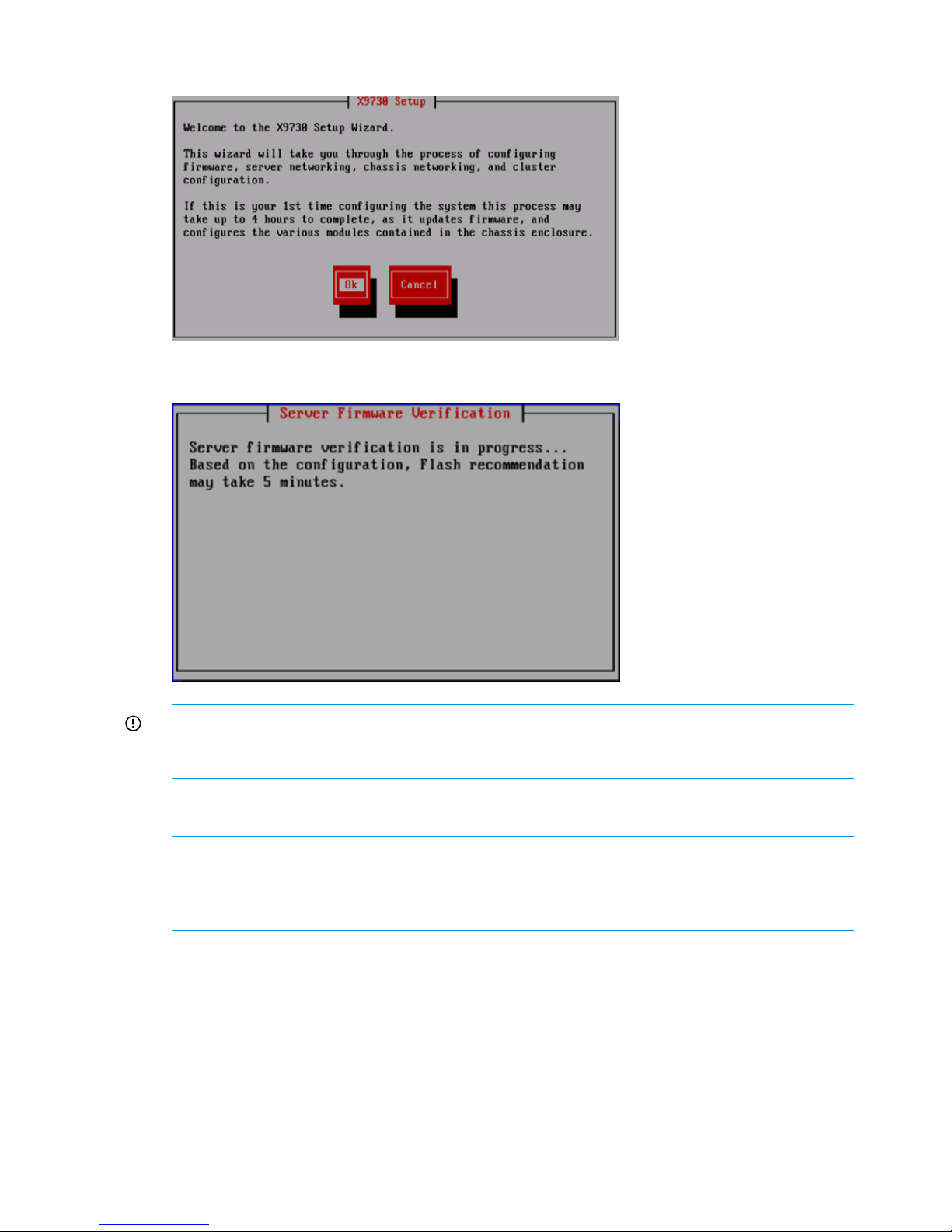
1. Log in to the blade. The X9730 Setup screen appears.
The wizard verifies the firmware on the system and notifies you if a firmware update is needed.
IMPORTANT: HP recommends that you update the firmware before continuing with the
installation. 9730 systems have been tested with specific firmware recipes. Continuing the
installation without upgrading to a supported firmware recipe can result in a defective system.
2. Provide the host name (blade name) on the Individual Server Setup screen. The installation
detects the time settings.
NOTE: The host name, which is the name of the local server, can include alphanumeric
characters and the hyphen (-) special character. It is a best practice to use only lowercase
characters in host names; uppercase characters can cause issues with HP StoreAll OS Software.
Do not use an underscore (_) in the host name.
96 Installing the HP StoreAll OS Software and configuring the HP StoreAll Storage system
Page 97

3. If needed, update the time settings on the Individual Server Setup screen. While setting the
time zone, press Enter while the cursor is positioned in the Time Zone field to display the list
of time zones in a separate screen. Enter the first letter of your time zone, or use the UP and
DOWN arrow keys to find your time zone. Select Ok to accept screen selections.
4. Complete field entry requirements for the Network Configuration screen. Note that on the
Network Configuration screen, the system defines the server on Bond0.
5. Complete the Network Configuration screen(s):
• Hostname: The host name (in the above example, Bond0) can include alphanumeric
characters and the hyphen (–) special character. It is a best practice to use a host name
with only lowercase characters; uppercase characters can cause issues with HP StoreAll
Storage system software. Do not use an underscore (_) in the host name.
• IP Address: The IP address is the address of the server on Bond0.
• Netmask: The netmask (a 32-bit mask) divides an IP address into subnets and specifies
the available network hosts. This field is auto-filled with 255.255.0.0, but the netmask
entry may need to be modified, based on your specific network subnets.
• Default Gateway: The default gateway provides a route between networks. If your default
gateway is on a different subnet than Bond0, skip this field.
• VLAN Tag ID: VLAN capabilities provide hardware support for running multiple logical
networks over the same physical networking hardware. HP StoreAll supports the ability
Configuring the HP StoreAll 9730 Storage systems 97
Page 98
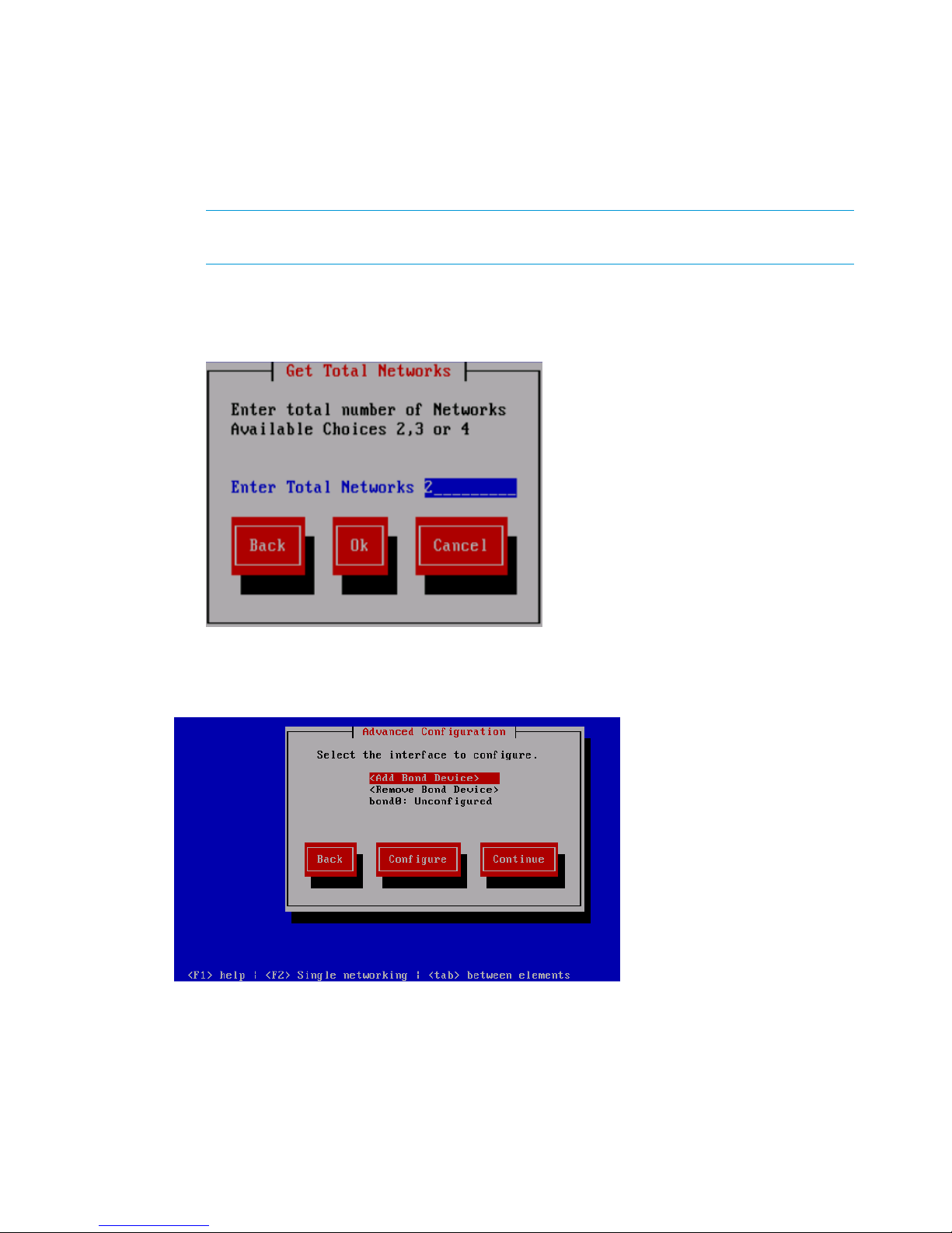
to associate a VLAN tag with an FSN interface. For more information, see the HP StoreAll
Storage Network Best Practices Guide.
• F2 (function key): If you press F2, you can toggle between the default Network
Configuration screen and the Get Network Totals and Advanced Configuration screens.
Use the Advanced Configuration screen to change default parameters; and specify the
number of networks and modify parameters, such as slaves, bond options, the network
role of any bond, and so forth.
NOTE: If multiple networks were chosen for HP StoreAll node 1, use F2 to choose the
number of networks to match HP StoreAll node 1.
6. If you need to configure more than one network, press F2 and complete the following:
a. Enter the total number of networks desired in the Enter Total Networks field of the Get
Total Networks screen.
b. Select Ok. The Advanced Configuration screen appears.
7. Select an interface and then select Continue.
The Configuration Summary lists your configuration.
8. Review displayed configurations, and then select Commit to continue with the installation.
98 Installing the HP StoreAll OS Software and configuring the HP StoreAll Storage system
Page 99
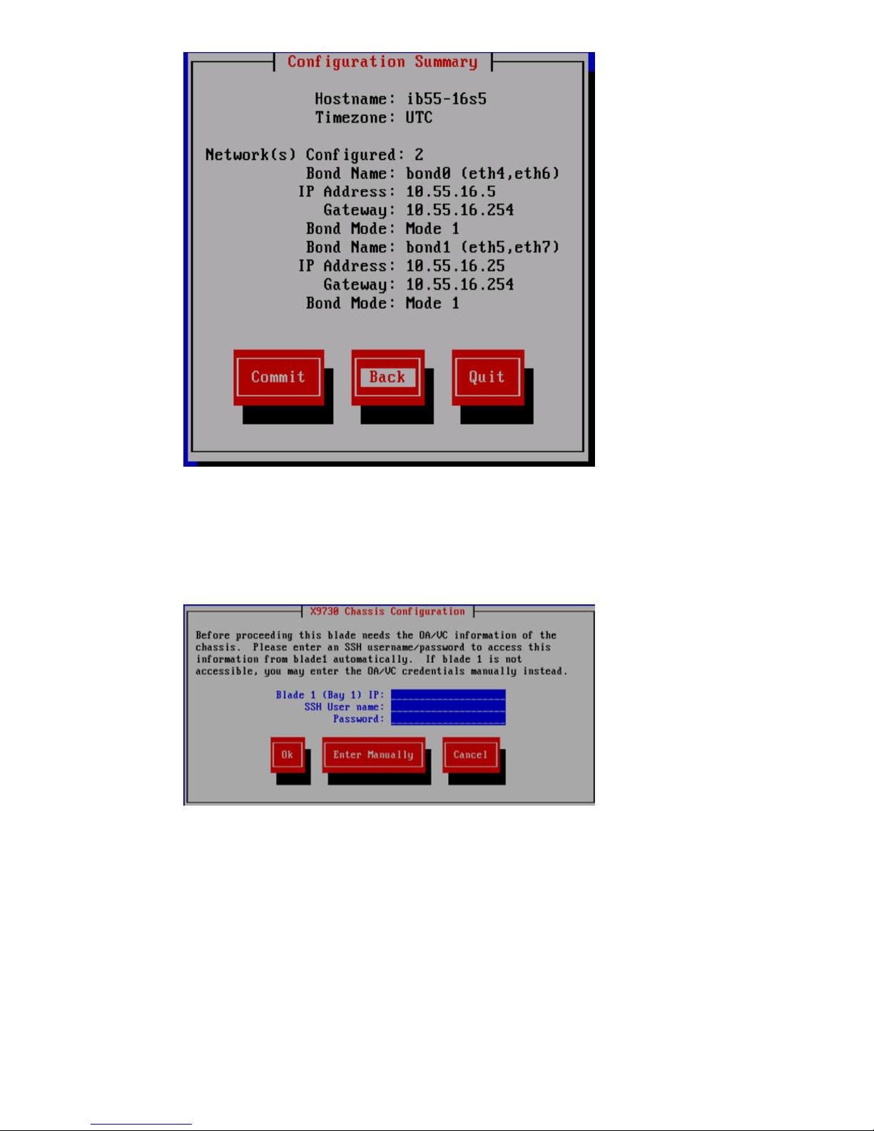
The wizard obtains OA/VC information from blade 1, uses the login credentials for blade 1,
and attempts to automatically enter an IP address.
9. If the wizard fails to acquire OA/VC information, the X9730 Chassis Configuration screen
appears. Before proceeding, enter the SSH User name and password to access OA/VC
information from blade 1 automatically, or enter the OA/VC credentials manually.
The wizard completes the following actions:
• Examines the OA and VC firmware and notifies you if an update is needed
• Verifies the VC configuration
• Creates the hpspAdmin user accounts on the iLOs
• Verifies the chassis configuration
• Examines the firmware on the SAS switches and notifies you if an update is needed
• Verifies the SAS configuration
• Examines the storage firmware and notifies you if an update is needed
Configuring the HP StoreAll 9730 Storage systems 99
Page 100

• Verifies the storage configuration
• Sets up networking on the blade
10. On the X9000 Installation - Network Setup Complete screen, select Join this StoreAll server
to an existing cluster.
The Join Cluster screen appears, and all available management consoles are displayed.
11. Select the applicable management console to complete the configuration, and then select Ok.
The wizard registers and starts a passive management console on the blade.
100 Installing the HP StoreAll OS Software and configuring the HP StoreAll Storage system
 Loading...