

Page 1

HP StorageWorks
X9720 Network Storage System
Administrator Guide
Abstract
This guide describes tasks related to cluster configuration and monitoring, system upgrade and recovery, hardware component
replacement, and troubleshooting. It does not document X9000 file system features or standard Linux administrative tools and
commands. For information about configuring and using X9000 Software file system features, see the HP StorageWorks X9000
File Serving Software File System User Guide.
This guide is intended for system administrators and technicians who are experienced with installing and administering networks,
and with performing Linux operating and administrative tasks.
HP Part Number: AW549-96023
Published: April 2011
Edition: Seventh
Page 2

© Copyright 2009, 2011 Hewlett-Packard Development Company, L.P.
Confidential computer software. Valid license from HP required for possession, use or copying. Consistent with FAR 12.211 and 12.212, Commercial
Computer Software, Computer Software Documentation, and Technical Data for Commercial Items are licensed to the U.S. Government under
vendor's standard commercial license.
The information contained herein is subject to change without notice. The only warranties for HP products and services are set forth in the express
warranty statements accompanying such products and services. Nothing herein should be construed as constituting an additional warranty. HP shall
not be liable for technical or editorial errors or omissions contained herein.
Acknowledgments
Microsoft® and Windows® are U.S. registered trademarks of Microsoft Corporation.
UNIX® is a registered trademark of The Open Group.
Warranty
WARRANTY STATEMENT: To obtain a copy of the warranty for this product, see the warranty information website:
http://www.hp.com/go/storagewarranty
Revision History
DescriptionSoftware
Version
DateEdition
Initial release of the X9720 Network Storage System.5.3.1December 2009First
Added network management and Support ticket.5.4April 2010Second
Added management console backup, migration to an agile management
console configuration, software upgrade procedures, and system recovery
procedures.
5.4.1August 2010Third
Revised upgrade procedure.5.4.1August 2010Forth
Added information about NDMP backups and configuring virtual interfaces,
and updated cluster procedures.
5.5December 2010Fifth
Updated segment evacuation information.5.5March 2011Sixth
Revised upgrade procedure.5.6April 2011Seventh
Page 3

Contents
1 Product description...................................................................................11
HP X9720 Network Storage System features...............................................................................11
System components.................................................................................................................11
HP X9000 Software features....................................................................................................11
High availability and redundancy.............................................................................................12
2 Getting started.........................................................................................13
Setting up the X9720 Network Storage System...........................................................................13
Installation steps................................................................................................................13
Additional configuration steps.............................................................................................13
Logging in to the X9720 Network Storage System.......................................................................14
Using the network..............................................................................................................14
Using the TFT keyboard/monitor..........................................................................................14
Using the serial link on the Onboard Administrator.................................................................14
Booting the system and individual server blades.........................................................................14
Management interfaces...........................................................................................................15
Using the GUI...................................................................................................................15
Customizing the GUI..........................................................................................................18
Adding user accounts for GUI access...................................................................................19
Using the CLI.....................................................................................................................19
Starting the array management software...............................................................................19
X9000 client interfaces.......................................................................................................19
X9000 Software manpages.....................................................................................................20
Changing passwords..............................................................................................................20
Configuring ports for a firewall.................................................................................................20
HP Insight Remote Support software..........................................................................................22
3 Configuring virtual interfaces for client access..............................................23
Network and VIF guidelines.....................................................................................................23
Creating a bonded VIF............................................................................................................23
Configuring standby backup nodes...........................................................................................23
Configuring NIC failover.........................................................................................................24
Configuring automated failover................................................................................................24
Example configuration.............................................................................................................24
Specifying VIFs in the client configuration...................................................................................24
Support for link state monitoring...............................................................................................25
4 Configuring failover..................................................................................26
Agile management consoles....................................................................................................26
Agile management console modes.......................................................................................26
Agile management consoles and failover..............................................................................26
Viewing information about management consoles..................................................................27
Cluster high availability...........................................................................................................27
Failover modes..................................................................................................................27
What happens during a failover..........................................................................................27
Setting up automated failover..............................................................................................28
Identifying standbys for file serving nodes.........................................................................28
Identifying power sources...............................................................................................28
Turning automated failover on and off..............................................................................30
Contents 3
Page 4

Manually failing over a file serving node..............................................................................30
Failing back a file serving node...........................................................................................31
Using network interface monitoring......................................................................................31
Setting up HBA monitoring..................................................................................................33
Discovering HBAs..........................................................................................................33
Identifying standby-paired HBA ports...............................................................................34
Turning HBA monitoring on or off....................................................................................34
Deleting standby port pairings........................................................................................34
Deleting HBAs from the configuration database.................................................................34
Displaying HBA information............................................................................................34
Checking the High Availability configuration.........................................................................35
5 Configuring cluster event notification...........................................................37
Setting up email notification of cluster events..............................................................................37
Associating events and email addresses................................................................................37
Configuring email notification settings..................................................................................37
Turning email notifications on or off......................................................................................37
Dissociating events and email addresses...............................................................................37
Testing email addresses......................................................................................................38
Viewing email notification settings........................................................................................38
Setting up SNMP notifications..................................................................................................38
Configuring the SNMP agent...............................................................................................39
Configuring trapsink settings................................................................................................39
Associating events and trapsinks..........................................................................................40
Defining views...................................................................................................................40
Configuring groups and users..............................................................................................41
Deleting elements of the SNMP configuration........................................................................41
Listing SNMP configuration information.................................................................................41
6 Configuring system backups.......................................................................42
Backing up the management console configuration.....................................................................42
Using NDMP backup applications............................................................................................42
Configuring NDMP parameters on the cluster........................................................................43
NDMP process management...............................................................................................43
Viewing or canceling NDMP sessions..............................................................................43
Starting, stopping, or restarting an NDMP Server..............................................................44
Viewing or rescanning tape and media changer devices.........................................................44
NDMP events....................................................................................................................45
7 Creating hostgroups for X9000 clients.........................................................46
How hostgroups work..............................................................................................................46
Creating a hostgroup tree........................................................................................................46
Adding an X9000 client to a hostgroup.....................................................................................47
Adding a domain rule to a hostgroup........................................................................................47
Viewing hostgroups.................................................................................................................47
Deleting hostgroups................................................................................................................48
Other hostgroup operations.....................................................................................................48
8 Monitoring cluster operations.....................................................................49
Monitoring the X9720 Network Storage System status.................................................................49
Monitoring intervals...........................................................................................................49
Viewing storage monitoring output.......................................................................................49
4 Contents
Page 5

Monitoring the status of file serving nodes..................................................................................49
Monitoring cluster events.........................................................................................................50
Viewing events..................................................................................................................50
Removing events from the events database table....................................................................51
Monitoring cluster health.........................................................................................................51
Health checks....................................................................................................................51
Health check reports..........................................................................................................51
Viewing logs..........................................................................................................................54
Viewing and clearing the Integrated Management Log (IML).........................................................54
Viewing operating statistics for file serving nodes........................................................................54
9 Maintaining the system.............................................................................56
Shutting down the system.........................................................................................................56
Shutting down the X9000 Software......................................................................................56
Powering off the X9720 system hardware..............................................................................56
Starting up the system.............................................................................................................57
Powering on the X9720 system hardware..............................................................................57
Starting the X9000 Software...............................................................................................57
Powering file serving nodes on or off.........................................................................................57
Performing a rolling reboot......................................................................................................57
Starting and stopping processes...............................................................................................58
Tuning file serving nodes and X9000 clients...............................................................................58
Migrating segments................................................................................................................60
Removing storage from the cluster.............................................................................................60
Maintaining networks..............................................................................................................62
Cluster and user network interfaces......................................................................................62
Adding user network interfaces............................................................................................62
Setting network interface options in the configuration database................................................63
Preferring network interfaces................................................................................................63
Unpreferring network interfaces...........................................................................................64
Making network changes....................................................................................................64
Changing the IP address for a Linux X9000 client..............................................................64
Changing the IP address for the cluster interface on a dedicated management console..........65
Changing the cluster interface.........................................................................................65
Managing routing table entries.......................................................................................65
Deleting a network interface...........................................................................................66
Viewing network interface information..................................................................................66
10 Migrating to an agile management console configuration............................67
Backing up the configuration....................................................................................................67
Performing the migration..........................................................................................................67
Converting the original management console node to a file serving node hosting the agile management
console.................................................................................................................................70
11 Upgrading the X9000 Software................................................................71
Automatic upgrades................................................................................................................71
Manual upgrades...................................................................................................................72
Preparing for the upgrade...................................................................................................72
Saving the node configuration.............................................................................................73
Performing the upgrade......................................................................................................73
Restoring the node configuration..........................................................................................74
Completing the upgrade.....................................................................................................74
Upgrading Linux X9000 clients.................................................................................................75
Contents 5
Page 6

Upgrading Windows X9000 clients..........................................................................................75
Upgrading firmware on X9720 systems.....................................................................................76
Troubleshooting upgrade issues................................................................................................76
Automatic upgrade............................................................................................................76
Manual upgrade...............................................................................................................77
12 Licensing...............................................................................................78
Viewing license terms..............................................................................................................78
Retrieving a license key...........................................................................................................78
Using AutoPass to retrieve and install permanent license keys........................................................78
13 Upgrading the X9720 Network Storage System hardware............................79
Adding new server blades.......................................................................................................79
Adding capacity blocks...........................................................................................................81
Carton contents.................................................................................................................81
Where to install the capacity blocks.....................................................................................82
Base cabinet additional capacity blocks...........................................................................82
Expansion cabinet additional capacity blocks...................................................................82
Installation procedure.........................................................................................................83
Step 1—Install X9700c in the cabinet..............................................................................83
Step 2—Install X9700cx in the cabinet.............................................................................84
Step 3—Cable the capacity block...................................................................................84
Step 4—Cable the X9700c to SAS switches......................................................................86
Base cabinet............................................................................................................86
Expansion cabinet....................................................................................................87
Step 5—Connect the power cords...................................................................................87
Step 6—Power on the X9700c and X9700cx components..................................................87
Step 7—Discover the capacity block and validate firmware versions....................................88
Removing server blades...........................................................................................................88
Removing capacity blocks........................................................................................................88
14 Upgrading firmware................................................................................89
Firmware update summary.......................................................................................................89
Locating firmware...................................................................................................................89
Upgrading Onboard Administrator...........................................................................................90
Upgrading all Virtual Connect modules.....................................................................................90
Upgrading X9700c controller firmware......................................................................................91
Upgrading X9700cx I/O module and disk drive firmware............................................................92
Upgrading SAS switch module firmware....................................................................................92
15 Troubleshooting......................................................................................94
Managing support tickets........................................................................................................94
Creating, viewing, and deleting support tickets......................................................................94
Support ticket states............................................................................................................95
Updating the ticket database when nodes are added or removed............................................95
Configuring the support ticket feature....................................................................................95
Configuring shared ssh keys................................................................................................95
General troubleshooting steps..................................................................................................96
Escalating issues.....................................................................................................................96
Useful utilities and processes....................................................................................................96
Accessing the Onboard Administrator (OA) through the network..............................................96
Access the OA Web-based administration interface...........................................................96
6 Contents
Page 7

Accessing the Onboard Administrator (OA) through the serial port...........................................96
Accessing the Onboard Administrator (OA) via service port....................................................97
Using hpacucli – Array Configuration Utility (ACU).................................................................97
The exds_stdiag utility........................................................................................................97
Syntax.........................................................................................................................98
Network testing tools..........................................................................................................98
exds_netdiag................................................................................................................99
Sample output..........................................................................................................99
exds_netperf.................................................................................................................99
POST error messages............................................................................................................100
LUN layout..........................................................................................................................100
X9720 monitoring................................................................................................................100
Identifying failed I/O modules on an X9700cx chassis..............................................................101
Failure indications............................................................................................................101
Identifying the failed component........................................................................................102
Re-seating an X9700c controller........................................................................................105
Viewing software version numbers..........................................................................................105
Troubleshooting specific issues................................................................................................106
Software services.............................................................................................................106
Failover..........................................................................................................................106
Windows X9000 clients...................................................................................................107
X9000 Software reinstall failed..........................................................................................107
Mode 1 or mode 6 bonding.............................................................................................107
X9000 RPC call to host failed............................................................................................108
Degrade server blade/Power PIC.......................................................................................108
ibrix_fs -c failed with "Bad magic number in super-block"......................................................108
LUN status is failed..........................................................................................................109
Apparent failure of HP P700m...........................................................................................109
X9700c enclosure front panel fault ID LED is amber..............................................................110
Spare disk drive not illuminated green when in use..............................................................110
Replacement disk drive LED is not illuminated green.............................................................110
X9700cx GSI LED is amber...............................................................................................110
X9700cx drive LEDs are amber after firmware is flashed.......................................................111
Configuring the Virtual Connect domain..................................................................................111
Synchronizing information on file serving nodes and the configuration database...........................112
16 Replacing components in the X9720 Network Storage System....................113
Customer replaceable components..........................................................................................113
Determining when to replace a component..............................................................................113
Hot-pluggable and non-hot-pluggable components....................................................................114
Returning the defective component..........................................................................................114
Parts-only warranty service.....................................................................................................114
Required tools......................................................................................................................114
Additional documentation......................................................................................................114
Replacing the c7000 blade enclosure and server blade parts.....................................................115
Replacing the blade enclosure...........................................................................................115
Replacing a server blade or system board of a server blade..................................................115
Replacing a server blade disk drive....................................................................................116
Replacing both disk drives.................................................................................................116
Replacing the Onboard Administrator (OA) module..............................................................116
Replacing the Ethernet Virtual Connect (VC) module (bay 1 or bay 2).....................................116
Replacing the SAS switch in Bay 3 or 4..............................................................................117
Replacing the P700m mezzanine card................................................................................118
Replacing capacity block parts...............................................................................................119
Contents 7
Page 8

Replacing capacity block hard disk drive............................................................................119
Replacing the X9700c controller........................................................................................119
Replacing the X9700c controller battery..............................................................................120
Replacing the X9700c power supply..................................................................................121
Replacing the X9700c fan.................................................................................................121
Replacing the X9700c chassis...........................................................................................121
Replacing the X9700cx I/O module ..................................................................................122
Replacing the X9700cx power supply.................................................................................123
Replacing the X9700cx fan...............................................................................................123
Replacing a SAS cable.....................................................................................................123
17 Recovering the X9720 Network Storage System........................................125
Starting the recovery.............................................................................................................125
Configuring a file serving node..............................................................................................126
Configuring a file serving node using the original template....................................................126
Completing the restore on a file serving node......................................................................129
Configuring a file serving node manually............................................................................131
Configuring the management console on the dedicated (non-agile) Management Server blade.......139
Completing the restore on the dedicated (non-agile) Management Server................................147
Troubleshooting....................................................................................................................147
iLO remote console does not respond to keystrokes...............................................................147
18 Support and other resources...................................................................148
Contacting HP......................................................................................................................148
Related information...............................................................................................................148
HP websites.........................................................................................................................149
Rack stability........................................................................................................................149
Customer self repair..............................................................................................................149
Product warranties................................................................................................................150
Subscription service..............................................................................................................150
A Component and cabling diagrams...........................................................151
Base and expansion cabinets.................................................................................................151
Front view of a base cabinet..............................................................................................151
Back view of a base cabinet with one capacity block...........................................................152
Front view of a full base cabinet.........................................................................................153
Back view of a full base cabinet.........................................................................................154
Front view of an expansion cabinet ...................................................................................155
Back view of an expansion cabinet with four capacity blocks.................................................156
Performance blocks (c-Class Blade enclosure)............................................................................156
Front view of a c-Class Blade enclosure...............................................................................156
Rear view of a c-Class Blade enclosure...............................................................................157
Flex-10 networks...............................................................................................................157
Capacity blocks...................................................................................................................158
X9700c (array controller with 12 disk drives).......................................................................159
Front view of an X9700c..............................................................................................159
Rear view of an X9700c..............................................................................................159
X9700cx (dense JBOD with 70 disk drives)..........................................................................160
Front view of an X9700cx............................................................................................160
Rear view of an X9700cx.............................................................................................160
Cabling diagrams................................................................................................................161
Capacity block cabling—Base and expansion cabinets........................................................161
Virtual Connect Flex-10 Ethernet module cabling—Base cabinet.............................................161
8 Contents
Page 9

SAS switch cabling—Base cabinet.....................................................................................163
SAS switch cabling—Expansion cabinet..............................................................................164
B Spare parts list ......................................................................................165
AW548A—Base Rack...........................................................................................................165
AW552A—X9700 Expansion Rack.........................................................................................165
AW549A—X9700 Server Chassis..........................................................................................166
AW550A—X9700 Blade Server ............................................................................................166
AW551A—X9700 Capacity Block (X9700c and X9700cx) .......................................................167
C Warnings and precautions......................................................................168
Electrostatic discharge information..........................................................................................168
Grounding methods..............................................................................................................168
Equipment symbols...............................................................................................................168
Weight warning...................................................................................................................169
Rack warnings and precautions..............................................................................................169
Device warnings and precautions...........................................................................................170
D Regulatory compliance and safety............................................................172
Regulatory compliance identification numbers..........................................................................172
Federal Communications Commission notice............................................................................172
Class A equipment...........................................................................................................172
Class B equipment...........................................................................................................172
Declaration of conformity for products marked with the FCC logo, United States only................173
Modifications..................................................................................................................173
Cables...........................................................................................................................173
Laser compliance..................................................................................................................173
International notices and statements........................................................................................174
Canadian notice (Avis Canadien)......................................................................................174
Class A equipment......................................................................................................174
Class B equipment......................................................................................................174
European Union notice.....................................................................................................174
BSMI notice....................................................................................................................174
Japanese notice...............................................................................................................174
Korean notice (A&B).........................................................................................................175
Safety.................................................................................................................................175
Battery Replacement notice...............................................................................................175
Taiwan Battery Recycling Notice...................................................................................175
Power cords....................................................................................................................175
Japanese Power Cord notice..............................................................................................176
Electrostatic discharge......................................................................................................176
Preventing electrostatic discharge..................................................................................176
Grounding methods.....................................................................................................176
Waste Electrical and Electronic Equipment directive...................................................................177
Czechoslovakian notice....................................................................................................177
Danish notice..................................................................................................................177
Dutch notice....................................................................................................................177
English notice..................................................................................................................178
Estonian notice................................................................................................................178
Finnish notice..................................................................................................................178
French notice...................................................................................................................178
German notice................................................................................................................179
Greek notice...................................................................................................................179
Contents 9
Page 10

Hungarian notice.............................................................................................................179
Italian notice...................................................................................................................179
Latvian notice..................................................................................................................180
Lithuanian notice..............................................................................................................180
Polish notice....................................................................................................................180
Portuguese notice.............................................................................................................180
Slovakian notice..............................................................................................................181
Slovenian notice..............................................................................................................181
Spanish notice.................................................................................................................181
Swedish notice................................................................................................................181
Glossary..................................................................................................182
Index.......................................................................................................184
10 Contents
Page 11

1 Product description
HP StorageWorks X9720 Network Storage System is a scalable, network-attached storage (NAS)
product. The system combines HP X9000 File Serving Software with HP server and storage hardware
to create a cluster of file serving nodes.
HP X9720 Network Storage System features
The X9720 Network Storage System provides the following features:
• Segmented, scalable file system under a single namespace
• NFS, CIFS, FTP, and HTTP support for accessing file system data
• Centralized CLI and GUI for cluster management
• Policy management
• Continuous remote replication
• Dual redundant paths to all storage components
• Gigabytes-per-second of throughput
IMPORTANT: It is important to keep regular backups of the cluster configuration. See “Backing
up the management console configuration” (page 42) for more information.
System components
The X9720 Network Storage System includes the following components:
• X9720 Network Storage System Base Rack, including
Two ProCurve 2810-24G management switches◦
◦ Keyboard, video, and mouse (KVM)
• X9720 Network Storage System performance chassis comprised of:
A c-Class blade enclosure◦
◦ Two Flex-10 Virtual Connect modules
◦ Redundant SAS switch pair
• Performance block comprised of a server blade and blade infrastructure
• Capacity block (array) (minimum of one) comprised of:
X9700c (array controller chassis and 12 disk drives)◦
◦ X9700cx (dense JBOD with 70 disk drives)
• Software for manageability, segmented file system, and file serving
IMPORTANT: All software that is included with the X9720 Network Storage System is for the
sole purpose of operating the system. Do not add, remove, or change any software unless instructed
to do so by HP-authorized personnel.
For more information about system components and cabling, see “Component and cabling
diagrams” (page 151).
HP X9000 Software features
HP X9000 Software is a scale-out, network-attached storage solution composed of a parallel file
system for clusters, an integrated volume manager, high-availability features such as automatic
HP X9720 Network Storage System features 11
Page 12

failover of multiple components, and a centralized management interface. X9000 Software can
be deployed in environments scaling to thousands of nodes.
Based on a Segmented File System architecture, X9000 Software enables enterprises to integrate
I/O and storage systems into a single clustered environment that can be shared across multiple
applications and managed from a single central management console.
X9000 Software is designed to operate with high-performance computing applications that require
high I/O bandwidth, high IOPS throughput, and scalable configurations. Examples of these
applications include Internet streaming, rich media streaming, data mining, web search,
manufacturing, financial modeling, life sciences modeling, and seismic processing.
Some of the key features and benefits are as follows:
• Scalable configuration. You can add servers to scale performance and add storage devices
to scale capacity.
• Single namespace. All directories and files are contained in the same namespace.
• Multiple environments. Operates in both the SAN and DAS environments.
• High availability. The high-availability software protects servers.
• Tuning capability. The system can be tuned for large or small-block I/O.
• Flexible configuration. Segments can be migrated dynamically for rebalancing and data
tiering.
High availability and redundancy
The segmented architecture is the basis for fault resilience—loss of access to one or more segments
does not render the entire file system inaccessible. Individual segments can be taken offline
temporarily for maintenance operations and then returned to the file system.
To ensure continuous data access, X9000 Software provides manual and automated failover
protection at various points:
• Server. A failed node is powered down and a designated standby server assumes all of its
segment management duties.
• Segment. Ownership of each segment on a failed node is transferred to a designated standby
server.
• Network interface. The IP address of a failed network interface is transferred to a standby
network interface until the original network interface is operational again.
• Storage connection. For servers with HBA-protected Fibre Channel access, failure of the HBA
triggers failover of the node to a designated standby server.
12 Product description
Page 13

2 Getting started
This chapter describes how to log into the system, how to boot the system and individual server
blades, how to change passwords, and how to back up the management console configuration.
It also describes the management interfaces provided with X9000 Software.
IMPORTANT: Do not modify any parameters of the operating system or kernel, or update any
part of the X9720 Network Storage System unless instructed to do so by HP; otherwise, the X9720
Network Storage System could fail to operate properly.
Setting up the X9720 Network Storage System
An HP service specialist sets up the X9720 Network Storage System at your site, including the
following tasks:
Installation steps
• Remove the product from the shipping cartons that you have placed in the location where the
product will be installed, confirm the contents of each carton against the list of included items
and check for any physical damage to the exterior of the product, and connect the product
to the power and network provided by you.
• Review your server, network, and storage environment relevant to the HP Enterprise NAS
product implementation to validate that prerequisites have been met.
• Validate that your file system performance, availability, and manageability requirements have
not changed since the service planning phase. Finalize the HP Enterprise NAS product
implementation plan and software configuration.
• Implement the documented and agreed-upon configuration based on the information you
provided on the pre-delivery checklist.
• Document configuration details.
Additional configuration steps
When your system is up and running, you can perform any additional configuration of your cluster
and file systems. The management console GUI and CLI are used to perform most operations.
(Some of the features described here might have been configured for you as part of the system
installation.)
Cluster. Configure the following as needed:
• Virtual interfaces for client access.
• Failover for file serving nodes, network interfaces, and HBAs.
• Cluster event notification through email or SNMP.
• Management console backups.
• NDMP backups.
These cluster features are described later in this guide.
File systems. Set up the following features as needed:
• Additional file systems. Optionally, configure data tiering on the file systems to move files to
specific tiers based on file attributes.
• NFS, CIFS, FTP, or HTTP. Configure the methods you will use to access file system data.
• Quotas. Configure user, group, and directory tree quotas as needed.
Setting up the X9720 Network Storage System 13
Page 14

• Remote replication. Use this feature to replicate changes in a source file system on one cluster
to a target file system on either the same cluster or a second cluster.
• Snapshots. Use this feature to capture a point-in-time copy of a file system.
• File allocation. Use this feature to specify the manner in which segments are selected for storing
new files and directories.
For more information about these file system features, see the HP StorageWorks File Serving
Software File System User Guide.
Logging in to the X9720 Network Storage System
Using the network
Use ssh to log in remotely from another host. You can log in to any server using any configured
site network interface (eth1, eth2, or bond1).
With ssh and the root user, after you log in to any server, your .ssh/known_hosts file will work
with any server in an X9720 Network Storage System.
The server blades in your original X9720 are configured to support password-less ssh between
them; after you have connected to one, you can reach the others without specifying the root
password again. If you wish to have the same support for additional server blades, or wish to
access the X9720 itself without specifying a password, add the keys of the other servers to .ssh/
authorized keys on each server blade.
Using the TFT keyboard/monitor
If the site network is down, you can log in to the console as follows:
1. Pull out the keyboard monitor (See “Front view of a base cabinet” (page 151)).
2. Access the on-screen display (OSD) main dialog box by pressing the Print Scrn key or by
pressing the Ctrl key twice within one second.
3. Double-click the first server name.
4. Log in as normal.
NOTE: By default, the first port is connected with the dongle to the front of blade 1 (that is, server
1). If server 1 is down, move the dongle to another blade.
Using the serial link on the Onboard Administrator
If you are connected to a terminal server, you can log in through the serial link on the Onboard
Administrator.
Booting the system and individual server blades
Before booting the system, ensure that all of the system components other than the server blades—the
capacity blocks and so on—are turned on. By default, server blades boot whenever power is
applied to the X9720 Network Storage System performance chassis (c-Class Blade enclosure). If
all server blades are powered off, you can boot the system as follows:
To boot the system:
1. Press the power button on server blade 1.
2. Log in as root to server 1.
14 Getting started
Page 15

3. To power on the remaining server blades, run the command:
ibrix_server -P on -h <hostname>
NOTE: Alternatively, press the power button on all of the remaining servers. There is no
need to wait for the first server blade to boot.
Management interfaces
Cluster operations are managed through the X9000 Software management console, which provides
both a GUI and a CLI. Most operations can be performed from either the GUI or the CLI. However,
the following operations can be performed only from the CLI:
• SNMP configuration (ibrix_snmpagent, ibrix_snmpgroup, ibrix_snmptrap,
ibrix_snmpuser, ibrix_snmpview)
• Health checks (ibrix_haconfig, ibrix_health, ibrix_healthconfig)
• Raw storage management (ibrix_pv, ibrix_vg, ibrix_lv)
• Management console operations (ibrix_fm) and management console tuning
(ibrix_fm_tune)
• File system checks (ibrix_fsck)
• Kernel profiling (ibrix_profile)
• NFS autoconnection (ibrix_autoconnect)
• Cluster configuration (ibrix_clusterconfig)
• Configuration database consistency (ibrix_dbck)
• Shell task management (ibrix_shell)
Using the GUI
The GUI is a browser-based interface to the management console. See the release notes for the
supported browsers and other software required to view charts on the dashboard.
If you are using HTTP to access the GUI, navigate to the following location, specifying port 80:
http://<management_console_IP>:80/fusion
If you are using HTTPS to access the GUI, navigate to the following location, specifying port 443:
https://<management_console_IP>:443/fusion
In these URLs, <management_console_IP> is the IP address of the management console user
VIF.
The GUI prompts for your user name and password. The default administrative user is ibrix.
Enter the password that was assigned to this user when the system was installed. (You can change
the password using the Linux passwd command.) To allow other users to access the GUI, see
“Adding user accounts for GUI access” (page 19).
Management interfaces 15
Page 16
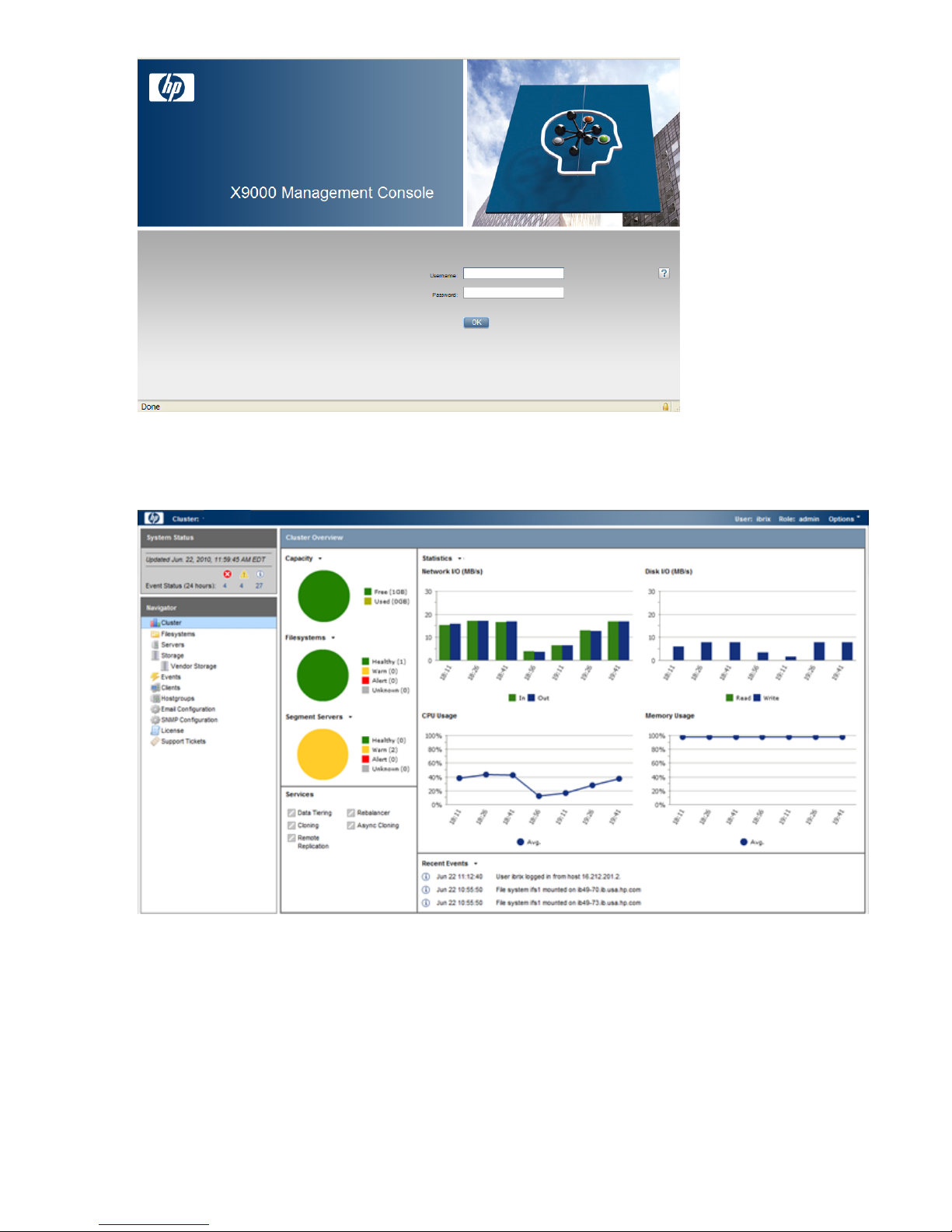
The GUI dashboard opens in the same browser window. You can open multiple GUI windows as
necessary. See the online help for information about all GUI displays and operations.
The GUI dashboard enables you to monitor the entire cluster. There are three parts to the dashboard:
System Status, Cluster Overview, and the Navigator.
16 Getting started
Page 17
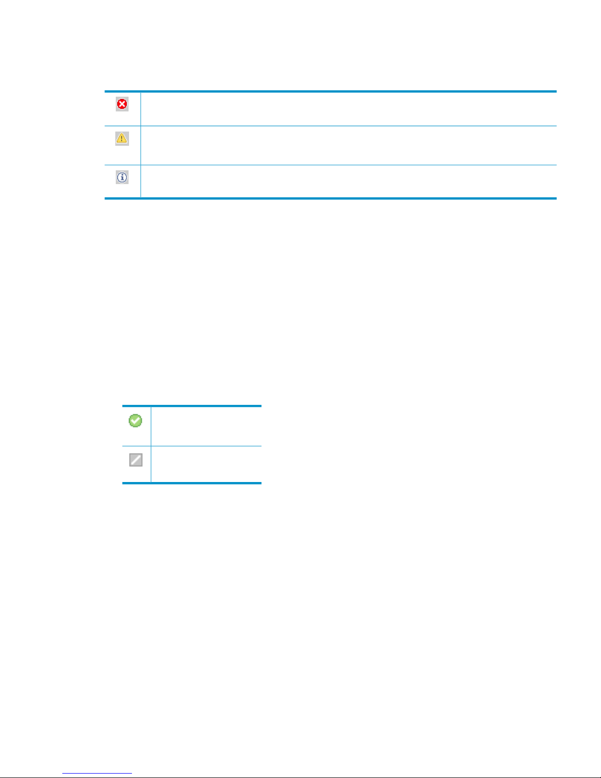
System Status
The System Status section lists the number of cluster events that have occurred in the last 24 hours.
There are three types of events:
Alerts. Disruptive events that can result in loss of access to file system data. Examples are a segment that is
unavailable or a server that cannot be accessed.
Warnings. Potentially disruptive conditions where file system access is not lost, but if the situation is not
addressed, it can escalate to an alert condition. Examples are a very high server CPU utilization level or a
quota limit close to the maximum.
Information. Normal events that change the cluster. Examples are mounting a file system or creating a
segment.
Cluster Overview
The Cluster Overview provides the following information:
Capacity
The amount of cluster storage space that is currently free or in use.
Filesystems
The current health status of the file systems in the cluster. The overview reports the number of
file systems in each state (healthy, experiencing a warning, experiencing an alert, or unknown).
Segment Servers
The current health status of the file serving nodes in the cluster. The overview reports the number
of nodes in each state (healthy, experiencing a warning, experiencing an alert, or unknown).
Services
Whether the specified file system services are currently running:
One or more tasks are
running.
No tasks are running.
Statistics
Historical performance graphs for the following items:
• Network I/O (MB/s)
• Disk I/O (MB/s)
• CPU usage (%)
• Memory usage (%)
On each graph, the X-axis represents time and the Y-axis represents performance.
Use the Statistics menu to select the servers to monitor (up to two), to change the maximum
value for the Y-axis, and to show or hide resource usage distribution for CPU and memory.
Recent Events
The most recent cluster events. Use the Recent Events menu to select the type of events to display.
You can also access certain menu items directly from the Cluster Overview. Mouse over the
Capacity, Filesystems or Segment Server indicators to see the available options.
Management interfaces 17
Page 18
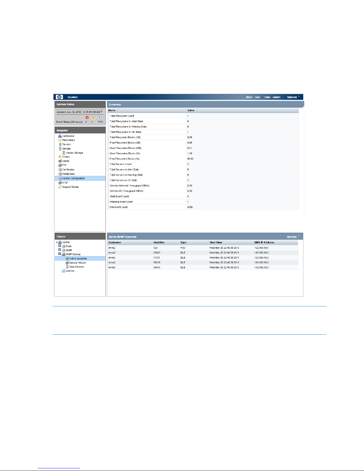
Navigator
The Navigator appears on the left side of the window and displays the cluster hierarchy. You can
use the Navigator to drill down in the cluster configuration to add, view, or change cluster objects
such as file systems or storage, and to initiate or view tasks such as snapshots or replication. When
you select an object, a details page shows a summary for that object. The lower Navigator allows
you to view details for the selected object, or to initiate a task. In the following example, we selected
Cluster Configuration in the Navigator, and the Summary shows configuration information. In the
lower Navigator, we selected NDMP Backup > Active Sessions to see details about the sessions.
NOTE: When you perform an operation on the GUI, a spinning finger is displayed until the
operation is complete. However, if you use Windows Remote Desktop to access the management
console, the spinning finger is not displayed.
Customizing the GUI
For most tables in the GUI, you can specify the columns that you want to display and the sort order
of each column. When this feature is available, mousing over a column causes the label to change
color and a pointer to appear. Click the pointer to see the available options. In the following
example, you can sort the contents of the Mountpoint column in ascending or descending order,
and you can select the columns that you want to appear in the display.
18 Getting started
Page 19

Adding user accounts for GUI access
X9000 Software supports administrative and user roles. When users log in under the administrative
role, they can configure the cluster and initiate operations such as remote replication or snapshots.
When users log in under the user role, they can view the cluster configuration and status, but cannot
make configuration changes or initiate operations. The default administrative user name is ibrix.
The default regular username is ibrixuser.
Usernames for the administrative and user roles are defined in the /etc/group file. Administrative
users are specified in the ibrix-admin group, and regular users are specified in the ibrix-user
group. These groups are created when X9000 Software is installed. The following entries in the
/etc/group file show the default users in these groups:
ibrix-admin:x:501:root,ibrix
ibrix-user:x:502:ibrix,ibrixUser,ibrixuser
You can add other users to these groups as needed, using Linux procedures.
Using the CLI
The administrative commands described in this guide must be executed on the management console
host and require root privileges. The commands are located in $IBRIXHOME⁄bin. For complete
information about the commands, see the HP StorageWorks X9000 File Serving Software CLI
Reference Guide.
When using ssh to access the machine hosting the management console, specify the IP address
of the management console user VIF.
Starting the array management software
Depending on the array type, you can launch the array management software from the management
console GUI. In the Navigator, select Vendor Storage, select your array from the Vendor Storage
page, and click Launch Storage Management.
X9000 client interfaces
X9000 clients can access the management console as follows:
• Linux clients. Linux client commands can be used for tasks such as mounting or unmounting
file systems and displaying statistics. See the HP StorageWorks X9000 File Serving Software
CLI Reference Guide for details about these commands.
• Windows clients. The Windows client GUI can be used for tasks such as mounting or
unmounting file systems and registering Windows clients.
Using the Windows X9000 client GUI
The Windows X9000 client GUI is the client interface to the management console. To open the
GUI, double-click the desktop icon or select the IBRIX Client program from the Start menu on the
client. The client program contains tabs organized by function.
Management interfaces 19
Page 20

NOTE: The Windows X9000 client application can be started only by users with Administrative
privileges.
• Status. Shows the client’s management console registration status and mounted file systems,
and provides access to the IAD log for troubleshooting.
• Registration. Registers the client with the management console, as described in the HP
StorageWorks File Serving Software Installation Guide.
• Mount. Mounts a file system. Select the Cluster Name from the list (the cluster name is the
management console name), enter the name of the file system to mount, select a drive, and
then click Mount. (If you are using Remote Desktop to access the client and the drive letter
does not appear, log out and log back in.)
• Umount. Unmounts a file system.
• Tune Host. Tunable parameters include the NIC to prefer (the client uses the cluster interface
by default unless a different network interface is preferred for it), the communications protocol
(UDP or TCP), and the number of server threads to use.
• Active Directory Settings. Displays current Active Directory settings.
Online help is also available for the client GUI.
X9000 Software manpages
X9000 Software provides manpages for most of its commands. To view the manpages, set the
MANPATH variable on the management console to include the path to the manpages and then
export it. The manpages are in the $IBRIXHOME/man directory. For example, if $IBRIXHOME is
/usr/local/ibrix (the default), you would set the MANPATH variable as follows on the
management console and then export the variable.
MANPATH=$MANPATH:/usr/local/ibrix/man
Changing passwords
You may want to change the passwords on your system:
• Hardware passwords. See the documentation for the specific hardware for more information.
• Root password. Use the passwd(8) command on each server in turn.
• X9000 Software user password. This password is created during installation and is used to
log on to the management console GUI. The default is ibrix. You can change the password
on the management console using the Linux passwd command. You will be prompted to enter
the new password.
# passwd ibrix
Configuring ports for a firewall
IMPORTANT: To avoid unintended consequences, HP recommends that you configure the firewall
during scheduled maintenance times.
When configuring a firewall, you should be aware of the following:
• SELinux should be disabled.
• By default, NFS uses random port numbers for operations such as mounting and locking.
These ports must be fixed so that they can be listed as exceptions in a firewall configuration
20 Getting started
Page 21

file. For example, you will need to lock specific ports for rpc.statd, rpc.lockd,
rpc.mountd, and rpc.quotad.
• It is best to allow all ICMP types on all networks; however, you can limit ICMP to types 0, 3,
8, and 11 if necessary.
Be sure to open the ports listed in the following table.
DescriptionPort
SSH22/tcp
SSH for Onboard Administrator (OA); only for X9720 blades9022/tcp
NTP123/tcp, 123/upd
Multicast DNS, 224.0.0.2515353/udp
netperf tool12865/tcp
X9000 management console to file serving nodes80/tcp
443/tcp
X9000 management console and X9000 file system5432/tcp
8008/tcp
9002/tcp
9005/tcp
9008/tcp
9009/tcp
9200/tcp
Between file serving nodes and NFS clients (user network)
NFS
RPC
quota
lockmanager
lockmanager
mount daemon
stat
stat outgoing
reserved for use by a custom application (CMU) and can be disabled if not used
2049/tcp, 2049/udp
111/tcp, 111/udp
875/tcp, 875/udp
32803/tcp
32769/udp
892/tcp, 892/udp
662/tcp, 662/udp
2020/tcp, 2020/udp
4000:4003/tcp
Between file serving nodes and CIFS clients (user network)137/udp
138/udp
139/tcp
445/tcp
Between file serving nodes and X9000 clients (user network)9000:9002/tcp
9000:9200/udp
Between file serving nodes and FTP clients (user network)20/tcp, 20/udp
21/tcp, 21/udp
Between X9000 management console GUI and clients that need to access the GUI7777/tcp
8080/tcp
Dataprotector5555/tcp, 5555/udp
Internet Printing Protocol (IPP)631/tcp, 631/udp
Configuring ports for a firewall 21
Page 22

HP Insight Remote Support software
HP Insight Remote Support supplements your monitoring, 24x7 to ensure maximum system availability
by providing intelligent event diagnosis, and automatic, secure submission of hardware event
notifications to HP, which will initiate a fast and accurate resolution, based on your product’s
service level. Notifications may be sent to your authorized HP Channel Partner for on-site service,
if configured and available in your country. The software is available in two variants:
• HP Insight Remote Support Standard: This software supports server and storage devices and
is optimized for environments with 1-50 servers. Ideal for customers who can benefit from
proactive notification, but do not need proactive service delivery and integration with a
management platform.
• HP Insight Remote Support Advanced: This software provides comprehensive remote monitoring
and proactive service support for nearly all HP servers, storage, network, and SAN
environments, plus selected non-HP servers that have a support obligation with HP. It is
integrated with HP Systems Insight Manager. A dedicated server is recommended to host both
HP Systems Insight Manager and HP Insight Remote Support Advanced.
Details for both versions are available at:
http://www.hp.com/go/insightremotesupport
The required components for HP Insight Remote Support are preinstalled on the file serving nodes.
You will need to install the Central Management Server (CMS) on a separate Windows system.
See the X9000 Series release notes for more information.
22 Getting started
Page 23

3 Configuring virtual interfaces for client access
X9000 Software uses a cluster network interface to carry management console traffic and traffic
between file serving nodes. This network is configured as bond0 when the cluster is installed. For
clusters with an agile management console configuration, a virtual interface is also created for the
cluster network interface to provide failover support for the console.
Although the cluster network interface can carry traffic between file serving nodes and clients, HP
recommends that you configure one or more user network interfaces for this purpose. Typically,
bond1 is created for the first user network when the cluster is configured.
To provide high availability for a user network, you should configure a bonded virtual interface
(VIF) for the network and then set up failover for the VIF. This method prevents interruptions to client
traffic. If necessary, the file serving node hosting the VIF can fail over to its standby backup node,
and clients can continue to access the file system through the backup node.
Network and VIF guidelines
To provide high availability, the user interfaces used for client access should be configured as
bonded virtual interfaces (VIFs). Note the following:
• Nodes needing to communicate for file system coverage or for failover must be on the same
network interface. Also, nodes set up as a failover pair must be connected to the same network
interface.
• Use a Gigabit Ethernet port (or faster) for user networks.
• NFS, CIFS, FTP, and HTTP clients can use the same user VIF. The servers providing the VIF
should be configured in backup pairs, and the NICs on those servers should also be configured
for failover.
• For X9000 Linux and Windows clients, the servers hosting the VIF should be configured in
backup pairs. However, X9000 clients do not support backup NICs. Instead, X9000 clients
should connect to the parent bond of the user VIF or to a different VIF.
Creating a bonded VIF
Use the following procedure to create a bonded VIF (bond1:1 in this example):
1. If high availability (automated failover) is configured on the servers, disable it. Run the following
command on the management console:
# ibrix_server –m -U
2. Identify the bond1:1 VIF:
# ibrix_nic –a -n bond1:1 –h node1,node2,node3,node4
3. Assign an IP address to the bond1:1 VIFs on each node. In the command, -I specifies the
IP address, -M specifies the netmask, and -B specifies the broadcast address:
# ibrix_nic –c –n bond1:1 –h node1 –I 16.123.200.201 –M 255.255.255.0 -B 16.123.200.255
# ibrix_nic –c –n bond1:1 –h node2 –I 16.123.200.202 –M 255.255.255.0 -B 16.123.200.255
# ibrix_nic –c –n bond1:1 –h node3 –I 16.123.200.203 –M 255.255.255.0 -B 16.123.200.255
# ibrix_nic –c –n bond1:1 –h node4 –I 16.123.200.204 –M 255.255.255.0 -B 16.123.200.255
Configuring standby backup nodes
Assign standby backup nodes for the bond1:1 interface. The backup nodes should be configured
in pairs. For example, node1 is the backup for node2, and node2 is the backup for node1.
Network and VIF guidelines 23
Page 24

1. Identify the VIF:
# ibrix_nic –a -n bond1:2 –h node1,node2,node3,node4
2. Set up a standby server for each VIF:
# ibric_nic –b –H node1/bond1:1,node2/bond1:2
# ibric_nic –b –H node2/bond1:1,node1/bond1:2
# ibric_nic –b –H node3/bond1:1,node4/bond1:2
# ibric_nic –b –H node4/bond1:1,node3/bond1:2
Configuring NIC failover
NIC monitoring should be configured on VIFs that will be used by NFS, CIFS, FTP, or HTTP. Use
the same backup pairs that you used when configuring standby servers. For example:
# ibric_nic –m -h node1 -A node2/bond1:1
# ibric_nic –m -h node2 -A node1/bond1:1
# ibric_nic –m -h node3 -A node4/bond1:1
# ibric_nic –m -h node4 -A node3/bond1:1
Configuring automated failover
To enable automated failover for your file serving nodes, execute the following command:
ibrix_server —m [-h SERVERNAME]
Example configuration
This example uses two nodes, ib50-81 and ib50-82. These nodes are backups for each other,
forming a backup pair.
[root@ib50-80 ~]# ibrix_server -l
Segment Servers
===============
SERVER_NAME BACKUP STATE HA ID GROUP
----------- ------- ------------ --- ------------------------------------ ----ib50-81 ib50-82 Up on 132cf61a-d25b-40f8-890e-e97363ae0d0b servers
ib50-82 ib50-81 Up on 7d258451-4455-484d-bf80-75c94d17121d servers
All VIFs on ib50-81 have backup (standby) VIFs on ib50-82. Similarly, all VIFs on ib50-82
have backup (standby) VIFs on ib50-81. NFS, CIFS, FTP, and HTTP clients can connect to bond1:1
on either host. If necessary, the selected server will fail over to bond1:2 on the opposite host.
X9000 clients could connect to bond1 on either host, as these clients do not support or require
NIC failover. (The following sample output shows only the relevant fields.)
[root@ib50-80 ~]# ibrix_nic -l
HOST IFNAME TYPE STATE IP_ADDRESS BACKUP_HOST BACKUP_IF
------- ------ ------- ------------------- ------------- ----------- --------ib50-81 bond1:1 User Up, LinkUp 16.226.50.220 ib50-82 bond1:1
ib50-81 bond0 Cluster Up, LinkUp 172.16.0.81
ib50-81 bond1:2 User Inactive, Standby
ib50-81 bond1 User Up, LinkUp 16.226.50.81
ib50-82 bond0 Cluster Up, LinkUp 172.16.0.82
ib50-82 bond1 User Up, LinkUp 16.226.50.82
ib50-82 bond1:2 User Inactive, Standby
ib50-82 bond1:1 User Up, LinkUp 16.226.50.228 ib50-81 bond1:1
Specifying VIFs in the client configuration
When you configure your clients, you may need to specify the VIF that should be used for client
access.
NFS/CIFS. Specify the VIF IP address of the servers (for example, bond1:0) to establish connection.
You can also configure DNS round robin to ensure NFS or CIFS client-to-server distribution. In both
cases, the NFS/CIFS clients will cache the initial IP they used to connect to the respective share,
usually until the next reboot.
24 Configuring virtual interfaces for client access
Page 25

FTP. When you add an FTP share on the Add FTP Shares dialog box or with the ibrix_ftpshare
command, specify the VIF as the IP address that clients should use to access the share.
HTTP. When you create a virtual host on the Create Vhost dialog box or with the
ibrix_httpvhost command, specify the VIF as the IP address that clients should use to access
shares associated with the Vhost.
X9000 clients. Use the following command to prefer the appropriate user network. Execute the
command once for each destination host that the client should contact using the specified interface.
ibrix_client -n -h SRCHOST -A DESTNOST/IFNAME
For example:
ibrix_client -n -h client12.mycompany.com -A ib50-81.mycompany.com/bond1
NOTE: Because the backup NIC cannot be used as a preferred network interface for X9000
clients, add one or more user network interfaces to ensure that HA and client communication work
together.
Support for link state monitoring
Do not configure link state monitoring for user network interfaces or VIFs that will be used for CIFS
or NFS. Link state monitoring is supported only for use with iSCSI storage network interfaces, such
as those provided with X9300 Gateway systems.
Support for link state monitoring 25
Page 26

4 Configuring failover
This chapter describes how to configure failover for agile management consoles, file serving nodes,
network interfaces, and HBAs.
Agile management consoles
The management console maintains the cluster configuration and provides graphical and
command-line user interfaces for managing and monitoring the cluster. Typically, one active
management console and one passive management console are installed when the cluster is
installed. This is called an agile management console configuration.
NOTE: Optionally, the management console can be installed on a dedicated Management
Server. This section describes the agile management console configuration.
Agile management console modes
An agile management console can be in one of the following modes:
• active. In this mode, the management console controls console operations. All cluster
administration and configuration commands must be run from the active management console.
• passive. In this mode, the management console monitors the health of the active management
console. If the active management console fails, the passive management console becomes
the active console.
• maintenance. In this mode, the management console does not participate in console operations.
Maintenance mode should be used for operations such as manual failover of the active
management console, X9000 Software upgrades, and blade replacements.
Agile management consoles and failover
Using an agile management console configuration provides high availability for management
console services. If the active management console fails, the cluster virtual interface will go down.
When the passive management console detects that the cluster virtual interface is down, it will
become the active console. This management console rebuilds the cluster virtual interface, starts
management console services locally, transitions into active mode, and take over management
console operation.
Failover of the active management console affects the following features:
• User networks. The virtual interface used by clients will also fail over. Users may notice a brief
reconnect while the newly active management console takes over management of the virtual
interface.
• Support tickets. The existing support ticket information is not moved to the newly active
management console. Support Ticket operations are always handled by the active management
console and the final output of the operations is stored there.
• Management console GUI. You will need to reconnect to the management console VIF after
the failover.
Failing over the management console manually
To fail over the active management console manually, place the console into maintenance mode.
Enter the following command on the node hosting the console:
ibrix_fm -m maintenance
The command takes effect immediately.
26 Configuring failover
Page 27

The failed-over management console remains in maintenance mode until it is moved to passive
mode using the following command:
ibrix_fm -m passive
A management console cannot be moved from maintenance mode to active mode.
Viewing information about management consoles
To view mode information, use the following command:
ibrix_fm –i
NOTE: If the management console was not installed in an agile configuration, the output will
report FusionServer: fusion manager name not set! (active, quorum is not
configured).
When a management console is installed, it is registered in the management console configuration.
To view a list of all registered management consoles, use the following command:
ibrix_fm –f
Cluster high availability
X9000 Software High Availability keeps your data accessible at all times. Failover protection can
be configured for file serving nodes, network interfaces, individual segments, and HBAs. Through
physical and logical configuration policies, you can set up a flexible and scalable high availability
solution. X9000 clients experience no changes in service and are unaware of the failover events.
Failover modes
High Availability has two failover modes: the default manual failover and the optional automated
failover. A manual failover uses the ibrix_server command or the management console GUI
to fail over a file serving node to its standby. The server can be powered down or remain up during
the procedure. Manual failover also includes failover of any network interfaces having defined
standbys. You can perform a manual failover at any time, regardless of whether automated failover
is in effect.
Automated failover allows the management console to initiate failover when it detects that
standby-protected components have failed. A basic automated failover setup protects all file serving
nodes. A comprehensive setup also includes network interface monitoring to protect user network
interfaces and HBA monitoring to protect access from file serving nodes to storage via an HBA.
When automated failover is enabled, the management console listens for heartbeat messages that
the file serving nodes broadcast at one-minute intervals. The management console automatically
initiates failover when it fails to receive five consecutive heartbeats or, if HBA monitoring is enabled,
when a heartbeat message indicates that a monitored HBA or pair of HBAs has failed.
If network interface monitoring is enabled, automated failover occurs when the management console
receives a heartbeat message indicating that a monitored network might be down and then the
console cannot reach that interface.
If a file serving node fails over, you will need to manually fail back the node.
What happens during a failover
The following events occur during automated or manual failover of a file serving node to its standby:
1. The management console verifies that the standby is powered on and accessible.
2. The management console migrates ownership of the node’s segments to the standby and
notifies all file serving nodes and X9000 clients about the migration. This is a persistent change.
3. If network interface monitoring has been set up, the management console activates the standby
user network interface and transfers the IP address of the node’s user network interface to it.
Cluster high availability 27
Page 28

To determine the progress of a failover, view the Status tab on the GUI or execute the
ibrix_server -l command. While the management console is migrating segment ownership,
the operational status of the node is Up-InFailover or Down-InFailover, depending on whether the
node was powered up or down when failover was initiated. When failover is complete, the
operational status changes to Up-FailedOver or Down-FailedOver. For more information about
operational states, see “Monitoring the status of file serving nodes” (page 49).
Both automated and manual failovers trigger an event that is reported on the GUI.
Setting up automated failover
The recommended minimum setup for automated failover protection is as follows:
1. Identify standbys for file serving nodes or specific segments. You must implement either
server-level or segment-level standby protection; you cannot implement both.
2. Identify power sources for file serving nodes. For APC power sources, associate file serving
nodes to power source slots.
3. Turn on automated failover.
If your cluster includes one or more user network interfaces carrying NFS/CIFS client traffic, HP
recommends that you identify standby network interfaces and set up network interface monitoring.
If your file serving nodes are connected to storage via HBAs, HP recommends that you set up HBA
monitoring.
Identifying standbys for file serving nodes
file serving nodes can be configured to provide standby service for one another in the following
configurations:
• 1 x 1. Set up standby pairs, where each server in a pair is the standby for the other.
• 1 x N. Assign the same standby to a certain number of primaries.
Contact HP Support for recommendations based on your environment.
The following restrictions apply to all types of standby configurations:
• The management console must have access to both the primary server and its standby.
• The same file system must be mounted on both the primary server and its standby.
• A server identified as a standby must be able to see all segments that might fail over to it.
• In a SAN environment, a primary server and its standby must use the same storage infrastructure
to access a segment’s physical volumes (for example, a multiported RAID array).
To identify a standby for a file serving node, use the following command:
<installdirectory>/bin/ibrix_server -b -h HOSTNAME1,HOSTNAME2
For example, to identify node s2.hp.com as the standby for all segments on node s1.hp.com:
<installdirectory>/bin/ibrix_server -b -h s1.hp.com,s2.hp.com
For performance reasons, you might want to fail over specific segments to a standby instead of
failing over all segments on a node to a standby. Use this command to identify the segments:
<installdirectory>/bin/ibrix_fs -b -f FSNAME -s LVLIST -h HOSTNAME
For example, to identify node s1.hp.com as the standby for segments ilv_1, ilv_2, and ilv_3 in file
system ifs1:
<installdirectory>/bin/ibrix_fs -b -f ifs1 -s ilv_1,ilv_2,ilv_3 -h s1.hp.com
Identifying power sources
To implement automated failover, perform a forced manual failover, or remotely power a file
serving node up or down, you must set up programmable power sources for the nodes and their
standbys. Using programmable power sources prevents a “split-brain scenario” between a failing
28 Configuring failover
Page 29

file serving node and its standby, allowing the failing server to be centrally powered down by the
management console in the case of automated failover, and manually in the case of a forced
manual failover.
X9000 Software works with iLO, IPMI, OpenIPMI, and OpenIPMI2 integrated power sources and
with APC power sources.
Preliminary configuration
Certain configuration steps are required when setting up power sources:
• All types. If you plan to implement automated failover, ensure that the management console
has LAN access to the power sources.
• Integrated power sources. Install the environment and any drivers and utilities, as specified
by the vendor documentation. If you plan to protect access to the power sources, set up the
UID and password to be used.
• APC. Enable SNMP access. Set the Community Name to ibrix and the Access Type to
write+. If write+ does not work with your configuration, set the Access Type to write.
Identifying power sources
All power sources must be identified to the configuration database before they can be used.
Integrated power sources. To identify an integrated power source, use the following command:
<installdirectory>/bin/ibrix_powersrc -a -t {ipmi|openipmi|openipmi2|ilo}
-h HOSTNAME -I IPADDR -u USERNAME -p PASSWORD
For example, to identify an iLO power source at IP address 192.168.3.170 for node ss01:
<installdirectory>/bin/ibrix_powersrc -a -t ilo -h ss01 -I 192.168.3.170
-u Administrator -p password
APC power source. To identify an APC power source, use the following command:
<installdirectory>/bin/ibrix_powersrc -a -t {apc|apc_msp} -h POWERSRCNAME -n NUMSLOTS
-I IPADDR
For example, to identify an eight-port APC power source named ps1 at IP address 192.168.3.150:
<installdirectory>/bin/ibrix_powersrc -a -t apc -h ps1 -n 8 -I 192.168.3.150
For APC power sources, you must also associate file serving nodes to power source slots. (This
step is unnecessary for integrated power sources because the nodes are connected by default to
slot 1.) Use the following command:
<installdirectory>/bin/ibrix_hostpower -a -i SLOTID -s POWERSOURCE -h HOSTNAME
For example, to identify that node s1.hp.com is connected to slot 1 on APC power source ps1:
<installdirectory>/bin/ibrix_hostpower -a -i 1 -s ps1 -h s1.hp.com
Updating the configuration database with power source changes
If you move a file serving node to a different power source slot, unplug it from a power source
slot, or change its IP address or password, you must update the configuration database with the
changes. To do this, use the following command. The user name and password options are needed
only for remotely managed power sources. Include the -s option to have the management console
skip BMC.
<installdirectory>/bin/ibrix_powersrc -m [-I IPADDR] [-u USERNAME] [-p PASSWORD]
[-s] -h POWERSRCLIST
The following command changes the IP address for power source ps1:
<installdirectory>/bin/ibrix_powersrc -m -I 192.168.3.153 -h ps1
To change the APC slot association for a file serving node, use the following command:
<installdirectory>/bin/ibrix_hostpower -m -i FROM_SLOT_ID,TO_SLOT_ID -s POWERSOURCE
-h HOSTNAME
Cluster high availability 29
Page 30

For example, to identify that node s1.hp.com has been moved from slot 3 to slot 4 on APC power
source ps1:
<installdirectory>/bin/ibrix_hostpower -m -i 3,4 -s ps1 -h s1.hp.com
Dissociating a file serving node from a power source
You can dissociate a file serving node from an integrated power source by dissociating it from
slot 1 (its default association) on the power source. Use the following command:
<installdirectory>/bin/ibrix_hostpower -d -s POWERSOURCE -h HOSTNAME
To dissociate a file serving node from an APC power source on the specified slot, use the following
command. To dissociate the node from all slots on the power source, omit the -i option.
<installdirectory>/bin/ibrix_hostpower -d [-s POWERSOURCE [-i SLOT]] -h HOSTNAME
For example, to dissociate file serving node s1.hp.com from slot 3 on APC power source ps1:
<installdirectory>/bin/ibrix_hostpower -d -s ps1 -i 3 -h s1.hp.com
Deleting power sources from the configuration database
To conserve storage, delete power sources that are no longer in use from the configuration database.
If you are deleting multiple power sources, use commas to separate them.
<installdirectory>/bin/ibrix_powersrc -d -h POWERSRCLIST
Turning automated failover on and off
Automated failover is turned off by default. When automated failover is turned on, the management
console starts monitoring heartbeat messages from file serving nodes. You can turn automated
failover on and off for all file serving nodes or for selected nodes.
To turn on automated failover, use the following command:
<installdirectory>/bin/ibrix_server -m [-h SERVERNAME]
To turn off automated failover, include the -U option:
<installdirectory>/bin/ibrix_server -m -U [-h SERVERNAME]
To turn automated failover on or off for a single file serving node, include the -h SERVERNAME
option.
Manually failing over a file serving node
To set up a cluster for manual failover, first identify server-level or segment-level standbys for each
file serving node, as described in “Identifying standbys for file serving nodes” (page 28).
Manual failover does not require the use of programmable power supplies. However, if you have
installed and identified power supplies for file serving nodes, you can power down a server before
manually failing it over. You can fail over a file serving node manually, even when automated
failover is turned on.
A file serving node can be failed over from the GUI or the CLI.
On the CLI, complete the following steps:
1. Run ibrix_server -f, specifying the node to be failed over in the HOSTNAME option. If
appropriate, include the -p option to power down the node before segments are migrated:
<installdirectory>/bin/ibrix_server -f [-p] -h HOSTNAME
2. Determine whether the failover was successful:
<installdirectory>/bin/ibrix_server -l
The contents of the STATE field indicate the status of the failover. If the field persistently shows
Down-InFailover or Up-InFailover, the failover did not complete; contact HP Support for assistance.
For information about the values that can appear in the STATE field, see “What happens during
a failover” (page 27).
30 Configuring failover
Page 31

Failing back a file serving node
After automated or manual failover of a file serving node, you must manually fail back the server,
which restores ownership of the failed-over segments and network interfaces to the server. Before
failing back the node, confirm that the primary server can see all of its storage resources and
networks. The segments owned by the primary server will not be accessible if the server cannot
see its storage.
To fail back a file serving node, use the following command. The HOSTNAME argument specifies
the name of the failed-over node.
<installdirectory>/bin/ibrix_server -f -U -h HOSTNAME
After failing back the node, determine whether the failback completed fully. If the failback is not
complete, contact HP Support for assistance.
NOTE: A failback might not succeed if the time period between the failover and the failback is
too short, and the primary server has not fully recovered. HP recommends ensuring that both servers
are up and running and then waiting 60 seconds before starting the failback. Use the
ibrix_server -l command to verify that the primary server is up and running. The status should
be Up-FailedOver before performing the failback.
Using network interface monitoring
With network interface monitoring, one file serving node monitors another file serving node over
a designated network interface. If the monitoring server loses contact with its destination server
over the interface, it notifies the management console. If the management console also cannot
contact the destination server over that interface, it fails over both the destination server and the
network interface to their standbys. Clients that were mounted on the failed-over server do not
experience any service interruption and are unaware that they are now mounting the file system
on a different server.
Unlike X9000 clients, NFS and CIFS clients cannot reroute file requests to a standby if the file
serving node where they are mounted should fail. To ensure continuous client access to files, HP
recommends that you put NFS/CIFS traffic on a user network interface (see “Preferring network
interfaces” (page 63)), and then implement network interface monitoring for it.
Comprehensive protection of NFS/CIFS traffic also involves setting up network interface monitoring
for the cluster interface. Although the management console will eventually detect interruption of a
file serving node’s connection to the cluster interface and initiate segment failover if automated
failover is turned on, failover will occur much faster if the interruption is detected via network
interface monitoring. (If automated failover is not turned on, you will begin to see file access
problems if the cluster interface fails.) There is no difference in the way that monitoring is set up
for the cluster interface and a user network interface. In both cases, you set up file serving nodes
to monitor each other over the interface.
Sample scenario
The following diagram illustrates a monitoring and failover scenario in which a 1:1 standby
relationship is configured. Each standby pair is also a network interface monitoring pair. When
SS1 loses its connection to the user network interface (eth1), as shown by the red X, SS2 can no
longer contact SS1 (A). SS2 notifies the management console, which then tests its own connection
with SS1 over eth1 (B). The management console cannot contact SS1 on eth1, and initiates
failover of SS1’s segments (C) and user network interface (D).
Cluster high availability 31
Page 32

Identifying standbys
To protect a network interface, you must identify a standby for it on each file serving node that
connects to the interface. The following restrictions apply when identifying a standby network
interface:
• The standby network interface must be unconfigured and connected to the same switch (network)
as the primary interface.
• The file serving node that supports the standby network interface must have access to the file
system that the clients on that interface will mount.
Virtual interfaces are highly recommended for handling user network interface failovers. If a VIF
user network interface is teamed/bonded, failover occurs only if all teamed network interfaces
fail. Otherwise, traffic switches to the surviving teamed network interfaces.
To identify standbys for a network interface, execute the following command once for each file
serving node. IFNAME1 is the network interface that you want to protect and IFNAME2 is the
standby interface.
<installdirectory>/bin/ibrix_nic -b -H HOSTNAME1/IFNAME1,HOSTNAME2/IFNAME2
The following command identifies virtual interface eth2:2 on file serving node s2.hp.com as the
standby interface for interface eth2 on file serving node s1.hp.com:
<installdirectory>/bin/ibrix_nic -b -H s1.hp.com/eth2,s2.hp.com/eth2:2
Setting up a monitor
File serving node failover pairs can be identified as network interface monitors for each other.
Because the monitoring must be declared in both directions, this is a two-pass process for each
failover pair.
To set up a network interface monitor, use the following command:
<installdirectory>/bin/ibrix_nic -m -h MONHOST -A DESTHOST/IFNAME
For example, to set up file serving node s2.hp.com to monitor file serving node s1.hp.com over
user network interface eth1:
<installdirectory>/bin/ibrix_nic -m -h s2.hp.com -A s1.hp.com/eth1
To delete network interface monitoring, use the following command:
<installdirectory>/bin/ibrix_nic -m -h MONHOST -D DESTHOST/IFNAME
32 Configuring failover
Page 33

Deleting standbys
To delete a standby for a network interface, use the following command:
<installdirectory>/bin/ibrix_nic -b -U HOSTNAME1/IFNAME1
For example, to delete the standby that was assigned to interface eth2 on file serving node
s1.hp.com:
<installdirectory>/bin/ibrix_nic -b -U s1.hp.com/eth2
Setting up HBA monitoring
You can configure High Availability to initiate automated failover upon detection of a failed HBA.
HBA monitoring can be set up for either dual-port HBAs with built-in standby switching or single-port
HBAs, whether standalone or paired for standby switching via software. X9000 Software does
not play any role in vendor- or software-mediated HBA failover—traffic moves to the remaining
functional port without any management console involvement.
HBAs use worldwide names for some parameter values. These are either worldwide node names
(WWNN) or worldwide port names (WWPN) The WWPN is the name an HBA presents when
logging in to a SAN fabric. Worldwide names consist of 16 hexadecimal digits grouped in pairs.
In X9000 Software, these are written as dot-separated pairs (for example,
21.00.00.e0.8b.05.05.04).
To set up HBA monitoring, first discover the HBAs, and then perform the procedure that matches
your HBA hardware:
• For single-port HBAs without built-in standby switching: Turn on HBA monitoring for all ports
that you want to monitor for failure (see “Turning HBA monitoring on or off” (page 34)).
• For dual-port HBAs with built-in standby switching and single-port HBAs that have been set
up as standby pairs via software: Identify the standby pairs of ports to the configuration
database (see “Identifying standby-paired HBA ports” (page 34), and then turn on HBA
monitoring for all paired ports (see “Turning HBA monitoring on or off” (page 34)). If monitoring
is turned on for just one port in a standby pair and that port then fails, the management console
will fail over the server even though the HBA has automatically switched traffic to the surviving
port. When monitoring is turned on for both ports, the management console initiates failover
only when both ports in a pair fail.
When both HBA monitoring and automated failover for file serving nodes are set up, the
management console will fail over a server in two situations:
• Both ports in a monitored set of standby-paired ports fail. Because, during the HBA monitoring
setup, all standby pairs were identified in the configuration database, the management console
knows that failover is required only when both ports fail.
• A monitored single-port HBA fails. Because no standby has been identified for the failed port,
the management console knows to initiate failover immediately.
Discovering HBAs
You must discover HBAs before you set up HBA monitoring, when you replace an HBA, and when
you add a new HBA to the cluster. Discovery informs the configuration database of only a port’s
WWPN. You must identify ports that are teamed as standby pairs. Use the following command:
<installdirectory>/bin/ibrix_hba -a [-h HOSTLIST]
Cluster high availability 33
Page 34

Identifying standby-paired HBA ports
Identifying standby-paired HBA ports to the configuration database allows the management console
to apply the following logic when they fail:
• If one port in a pair fails, do nothing. Traffic will automatically switch to the surviving port, as
configured by the vendor or the software.
• If both ports in a pair fail, fail over the server’s segments to the standby server.
Use the following command to identify two HBA ports as a standby pair:
<installdirectory>/bin/ibrix_hba -b -P WWPN1:WWPN2 -h HOSTNAME
Enter the WWPN as decimal-delimited pairs of hexadecimal digits. The following command
identifies port 20.00.12.34.56.78.9a.bc as the standby for port 42.00.12.34.56.78.9a.bc for
the HBA on file serving node s1.hp.com:
<installdirectory>/bin/ibrix_hba -b -P 20.00.12.34.56.78.9a.bc:42.00.12.34.56.78.9a.bc
-h s1.hp.com
Turning HBA monitoring on or off
If your cluster uses single-port HBAs, turn on monitoring for all of the ports to set up automated
failover in the event of HBA failure. Use the following command:
<installdirectory>/bin/ibrix_hba -m -h HOSTNAME -p PORT
For example, to turn on HBA monitoring for port 20.00.12.34.56.78.9a.bc on node s1.hp.com:
<installdirectory>/bin/ibrix_hba -m -h s1.hp.com -p 20.00.12.34.56.78.9a.bc
To turn off HBA monitoring for an HBA port, include the -U option:
<installdirectory>/bin/ibrix_hba -m -U -h HOSTNAME -p PORT
Deleting standby port pairings
Deleting port pairing information from the configuration database does not remove the standby
pairing of the ports. The standby pairing is either built in by the vendor or implemented by software.
To delete standby-paired HBA ports from the configuration database, enter the following command:
<installdirectory>/bin/ibrix_hba -b -U -P WWPN1:WWPN2 -h HOSTNAME
For example, to delete the pairing of ports 20.00.12.34.56.78.9a.bc and
42.00.12.34.56.78.9a.bc on node s1.hp.com:
<installdirectory>/bin/ibrix_hba -b -U -P 20.00.12.34.56.78.9a.bc:42.00.12.34.56.78.9a.bc
-h s1.hp.com
Deleting HBAs from the configuration database
Before switching an HBA card to a different machine, delete the HBA from the configuration
database. Use the following command:
<installdirectory>/bin/ibrix_hba -d -h HOSTNAME -w WWNN
Displaying HBA information
Use the following command to view information about the HBAs in the cluster. To view information
for all hosts, omit the -h HOSTLIST argument.
<installdirectory>/bin/ibrix_hba -l [-h HOSTLIST]
The following table describes the fields in the output.
DescriptionField
Server on which the HBA is installed.Host
This HBA’s WWNN.Node WWN
This HBA’s WWPN.Port WWN
34 Configuring failover
Page 35

DescriptionField
Operational state of the port.Port State
WWPN of the standby port for this port (standby-paired HBAs only).Backup Port WWN
Whether HBA monitoring is enabled for this port.Monitoring
Checking the High Availability configuration
Use the ibrix_haconfig command to determine whether High Availability features have been
configured for specific file serving nodes. The command checks for the following features and
provides either a summary or a detailed report of the results:
• Programmable power source
• Standby server or standby segments
• Cluster and user network interface monitors
• Standby network interface for each user network interface
• HBA port monitoring
• Whether automated failover is on
For each High Availability feature, the summary report returns one of the following results for each
tested file serving node and optionally for their standbys:
• Passed. The feature has been configured.
• Warning. The feature has not been configured, but the significance of the finding is not clear.
For example, the absence of discovered HBAs can indicate either that the HBA monitoring
feature was not configured or that HBAs are not physically present on the tested servers.
• Failed. The feature has not been configured.
The detailed report includes an overall result status for all tested file serving nodes and describes
details about the checks performed on each High Availability feature. By default, the report includes
details only about checks that received a Failed or a Warning result. You can expand the report
to include details about checks that received a Passed result.
Viewing a summary report
Executing the ibrix_haconfig command with no arguments returns a summary of all file serving
nodes. To check specific file serving nodes, include the -h HOSTLIST argument. To check standbys,
include the -b argument. To view results only for file serving nodes that failed a check, include
the -f argument.
<installdirectory>/bin/ibrix_haconfig -l [-h HOSTLIST] [-f] [-b]
For example, to view a summary report for file serving nodes xs01.hp.com and xs02.hp.com:
<installdirectory>/bin/ibrix_haconfig -l -h xs01.hp.com,xs02.hp.com
Host HA Configuration Power Sources Backup Servers Auto Failover
Nics Monitored Standby Nics HBAs Monitored
xs01.hp.com FAILED PASSED PASSED PASSED
FAILED PASSED FAILED
xs02.hp.com FAILED PASSED FAILED FAILED
FAILED WARNED WARNED
Viewing a detailed report
Execute the ibrix_haconfig -i command to view the detailed report:
<installdirectory>/bin/ibrix_haconfig -i [-h HOSTLIST] [-f] [-b] [-s] [-v]
Cluster high availability 35
Page 36

The -h HOSTLIST option lists the nodes to check. To also check standbys, include the -b option.
To view results only for file serving nodes that failed a check, include the -f argument. The -s
option expands the report to include information about the file system and its segments. The -v
option produces detailed information about configuration checks that received a Passed result.
For example, to view a detailed report for file serving nodes xs01.hp.com:
<installdirectory>/bin/ibrix_haconfig -i -h xs01.hp.com
--------------- Overall HA Configuration Checker Results ---------------
FAILED
--------------- Overall Host Results ---------------
Host HA Configuration Power Sources Backup Servers Auto Failover Nics Monitored
Standby Nics HBAs Monitored
xs01.hp.com FAILED PASSED PASSED PASSED FAILED
PASSED FAILED
--------------- Server xs01.hp.com FAILED Report ---------------
Check Description Result Result Information
================================================ ====== ==================
Power source(s) configured PASSED
Backup server or backups for segments configured PASSED
Automatic server failover configured PASSED
Cluster & User Nics monitored
Cluster nic xs01.hp.com/eth1 monitored FAILED Not monitored
User nics configured with a standby nic PASSED
HBA ports monitored
Hba port 21.01.00.e0.8b.2a.0d.6d monitored FAILED Not monitored
Hba port 21.00.00.e0.8b.0a.0d.6d monitored FAILED Not monitored
36 Configuring failover
Page 37

5 Configuring cluster event notification
Setting up email notification of cluster events
You can set up event notifications by event type or for one or more specific events. To set up
automatic email notification of cluster events, associate the events with email recipients and then
configure email settings to initiate the notification process.
Associating events and email addresses
You can associate any combination of cluster events with email addresses: all Alert, Warning, or
Info events, all events of one type plus a subset of another type, or a subset of all types.
The notification threshold for Alert events is 90% of capacity. Threshold-triggered notifications are
sent when a monitored system resource exceeds the threshold and are reset when the resource
utilization dips 10% below the threshold. For example, a notification is sent the first time usage
reaches 90% or more. The next notice is sent only if the usage declines to 80% or less (event is
reset), and subsequently rises again to 90% or above.
To associate all types of events with recipients, omit the -e argument in the following command.
Use the ALERT, WARN, and INFO keywords to make specific type associations or use EVENTLIST
to associate specific events.
<installdirectory>/bin/ibrix_event -c [-e ALERT|WARN|INFO|EVENTLIST] -m EMAILLIST
The following command associates all types of events to admin@hp.com:
<installdirectory>/bin/ibrix_event -c -m admin@hp.com
The next command associates all Alert events and two Info events to admin@hp.com:
<installdirectory>/bin/ibrix_event -c -e ALERT,server.registered,filesystem.space.full
-m admin@hp.com
Configuring email notification settings
Configuring email notification settings involves specifying the SMTP server and header information
and turning the notification process on or off. The state of the email notification process has no
effect on the display of cluster events in the management console GUI.
The server must be able to receive and send email and must recognize the From and Reply-to
addresses. Be sure to specify valid email addresses, especially for the SMTP server. If an address
is not valid, the SMTP server will reject the email.
<installdirectory>/bin/ibrix_event -m on|off -s SMTP -f from [-r reply-to] [-t subject]
The following command configures email settings to use the mail.hp.com SMTP server and to turn
on notifications:
<installdirectory>/bin/ibrix_event -m on -s mail.hp.com -f FM@hp.com
-r MIS@hp.com -t Cluster1 Notification
Turning email notifications on or off
After configuration is complete, use the -m on option to turn on email notifications. To turn off
email notifications, use the -m off option.
<installdirectory>/bin/ibrix_event -m on|off -s SMTP -f from
Dissociating events and email addresses
To remove the association between events and email addresses, use the following command:
<installdirectory>/bin/ibrix_event -d [-e ALERT|WARN|INFO|EVENTLIST] -m EMAILLIST
For example, to dissociate event notifications for admin@hp.com:
<installdirectory>/bin/ibrix_event -d -m admin@hp.com
Setting up email notification of cluster events 37
Page 38

To turn off all Alert notifications for admin@hp.com:
<installdirectory>/bin/ibrix_event -d -e ALERT -m admin@hp.com
To turn off the server.registered and filesystem.created notifications for
admin1@hp.com and admin2@hp.com:
<installdirectory>/bin/ibrix_event -d -e server.registered,filesystem.created
-m admin1@hp.com,admin2@hp.com
Testing email addresses
To test an email address with a test message, notifications must be turned on. If the address is
valid, the command signals success and sends an email containing the settings to the recipient. If
the address is not valid, the command returns an address failed exception.
<installdirectory>/bin/ibrix_event -u -n EMAILADDRESS
Viewing email notification settings
The ibrix_event command provides comprehensive information about email settings and
configured notifications.
<installdirectory>/bin/ibrix_event -L
Sample output follows:
Email Notification : Enabled
SMTP Server : mail.hp.com
From : FM@hp.com
Reply To : MIS@hp.com
EVENT LEVEL TYPE DESTINATION
------------------------------------- ----- ----- -----------
asyncrep.completed ALERT EMAIL admin@hp.com
asyncrep.failed ALERT EMAIL admin@hp.com
Setting up SNMP notifications
X9000 Software supports SNMP (Simple Network Management Protocol) V1, V2, and V3.
NOTE: Users of software versions earlier than 4.3 should be aware that the single ibrix_snmp
command has been replaced by two commands, ibrix_snmpagent and ibrix_snmptrap.
If you have scripts that include ibrix_snmp, be sure to edit them to include the correct commands.
Whereas SNMPV2 security was enforced by use of community password strings, V3 introduces
the USM and VACM. Discussion of these models is beyond the scope of this document. Refer to
RFCs 3414 and 3415 at http://www.ietf.org for more information. Note the following:
• In the SNMPV3 environment, every message contains a user name. The function of the USM
is to authenticate users and ensure message privacy through message encryption and
decryption. Both authentication and privacy, and their passwords, are optional and will use
default settings where security is less of a concern.
• With users validated, the VACM determines which managed objects these users are allowed
to access. The VACM includes an access scheme to control user access to managed objects;
context matching to define which objects can be accessed; and MIB views, defined by subsets
of IOD subtree and associated bitmask entries, which define what a particular user can access
in the MIB.
Steps for setting up SNMP include:
• Agent configuration (all SNMP versions)
• Trapsink configuration (all SNMP versions)
38 Configuring cluster event notification
Page 39

• Associating event notifications with trapsinks (all SNMP versions)
• View definition (V3 only)
• Group and user configuration (V3 only)
X9000 Software implements an SNMP agent on the management console that supports the private
X9000 Software MIB. The agent can be polled and can send SNMP traps to configured trapsinks.
Setting up SNMP notifications is similar to setting up email notifications. You must associate events
to trapsinks and configure SNMP settings for each trapsink to enable the agent to send a trap
when an event occurs.
Configuring the SNMP agent
The SNMP agent is created automatically when the management console is installed. It is initially
configured as an SNMPv2 agent and is off by default.
Some SNMP parameters and the SNMP default port are the same, regardless of SNMP version.
The agent port is 161 by default. SYSCONTACT, SYSNAME, and SYSLOCATION are optional MIB-II
agent parameters that have no default values.
The -c and -s options are also common to all SNMP versions. The -c option turns the encryption
of community names and passwords on or off. There is no encryption by default. Using the -s
option toggles the agent on and off; it turns the agent on by starting a listener on the SNMP port,
and turns it off by shutting off the listener. The default is off.
The format for a v1 or v2 update command follows:
ibrix_snmpagent -u –v {1|2} [-p PORT] [-r READCOMMUNITY] [-w WRITECOMMUNITY]
[-t SYSCONTACT] [-n SYSNAME] [-o SYSLOCATION] [-c {yes|no}] [-s {on|off}]
The update command for SNMPv1 and v2 uses optional community names. By convention, the
default READCOMMUNITY name used for read-only access and assigned to the agent is public.
No default WRITECOMMUNITY name is set for read-write access (although the name private is
often used).
The following command updates a v2 agent with the write community name private, the agent’s
system name, and that system’s physical location:
ibrix_snmpagent -u –v 2 -w private -n agenthost.domain.com -o DevLab-B3-U6
The SNMPv3 format adds an optional engine id that overrides the default value of the agent’s
host name. The format also provides the -y and -z options, which determine whether a v3 agent
can process v1/v2 read and write requests from the management station. The format is:
ibrix_snmpagent -u –v 3 [-e engineId] [-p PORT] [-r READCOMMUNITY]
[-w WRITECOMMUNITY] [-t SYSCONTACT] [-n SYSNAME] [-o SYSLOCATION]
[-y {yes|no}] [-z {yes|no}] [-c {yes|no}] [-s {on|off}]
Configuring trapsink settings
A trapsink is the host destination where agents send traps, which are asynchronous notifications
sent by the agent to the management station. A trapsink is specified either by name or IP address.
X9000 Software supports multiple trapsinks; you can define any number of trapsinks of any SNMP
version, but you can define only one trapsink per host, regardless of the version.
At a minimum, trapsink configuration requires a destination host and SNMP version. All other
parameters are optional and many assume the default value if no value is specified. Trapsink
configuration for SNMPv3 is more detailed than for earlier versions. The main differences involve
the additional security parameters added by SNMPv3.
The format for creating a v1/v2 trapsink is:
ibrix_snmptrap -c -h HOSTNAME -v {1|2} [-p PORT] [-m COMMUNITY] [-s {on|off}]
If a port is not specified, the command defaults to port 162. If a community is not specified, the
command defaults to the community name public. The -s option toggles agent trap transmission
Setting up SNMP notifications 39
Page 40

on and off. The default is on. For example, to create a v2 trapsink with a new community name,
enter:
ibrix_snmptrap -c -h lab13-116 -v 2 -m private
For a v3 trapsink, additional options define security settings. USERNAME is a v3 user defined on
the trapsink host and is required. The security level associated with the trap message depends on
which passwords are specified—the authentication password, both the authentication and privacy
passwords, or no passwords. The CONTEXT_NAME is required if the trap receiver has defined
subsets of managed objects. The format is:
ibrix_snmptrap -c -h HOSTNAME -v 3 [-p PORT] -n USERNAME [-j {MD5|SHA}]
[-k AUTHORIZATION_PASSWORD] [-y {DES|AES}] [-z PRIVACY_PASSWORD]
[-x CONTEXT_NAME] [-s {on|off}]
The following command creates a v3 trapsink with a named user and specifies the passwords to
be applied to the default algorithms. If specified, passwords must contain at least eight characters.
ibrix_snmptrap -c -h lab13-114 -v 3 -n trapsender -k auth-passwd -z priv-passwd
Associating events and trapsinks
Associating events with trapsinks is similar to associating events with email recipients, except that
you specify the host name or IP address of the trapsink instead of an email address.
Use the ibrix_event command to associate SNMP events with trapsinks. The format is:
<installdirectory>/bin/ibrix_event -c -y SNMP [-e ALERT|INFO|EVENTLIST]
-m TRAPSINK
For example, to associate all Alert events and two Info events with a trapsink at IP address
192.168.2.32, enter:
<installdirectory>/bin/ibrix_event -c -y SNMP -e ALERT,server.registered,
filesystem.created -m 192.168.2.32
Use the ibrix_event -d command to dissociate events and trapsinks:
<installdirectory>/bin/ibrix_event -d -y SNMP [-e ALERT|INFO|EVENTLIST] -m TRAPSINK
Defining views
A MIB view is a collection of paired OID subtrees and associated bitmasks that identify which
subidentifiers are significant to the view’s definition. Using the bitmasks, individual OID subtrees
can be included in or excluded from the view.
An instance of a managed object belongs to a view if:
• The OID of the instance has at least as many sub-identifiers as the OID subtree in the view.
• Each sub-identifier in the instance and the subtree match when the bitmask of the corresponding
sub-identifier is nonzero.
The management console automatically creates the excludeAll view that blocks access to all
OIDs. This view cannot be deleted; it is the default read and write view if one is not specified for
a group with the ibrix_snmpgroup command. The catch-all OID and mask are:
OID = .1
Mask = .1
Consider these examples, where instance .1.3.6.1.2.1.1 matches, instance .1.3.6.1.4.1 matches,
and instance .1.2.6.1.2.1 does not match.
OID = .1.3.6.1.4.1.18997
Mask = .1.1.1.1.1.1.1
OID = .1.3.6.1.2.1
Mask = .1.1.0.1.0.1
To add a pairing of an OID subtree value and a mask value to a new or existing view, use the
following format:
40 Configuring cluster event notification
Page 41

ibrix_snmpview -a -v VIEWNAME [-t {include|exclude}] -o OID_SUBTREE [-m MASK_BITS]
The subtree is added in the named view. For example, to add the X9000 Software private MIB to
the view named hp, enter:
ibrix_snmpview -a -v hp -o .1.3.6.1.4.1.18997 -m .1.1.1.1.1.1.1
Configuring groups and users
A group defines the access control policy on managed objects for one or more users. All users
must belong to a group. Groups and users exist only in SNMPv3. Groups are assigned a security
level, which enforces use of authentication and privacy, and specific read and write views to
identify which managed objects group members can read and write.
The command to create a group assigns its SNMPv3 security level, read and write views, and
context name. A context is a collection of managed objects that can be accessed by an SNMP
entity. A related option, -m, determines how the context is matched. The format follows:
ibrix_snmpgroup -c -g GROUPNAME [-s {noAuthNoPriv|authNoPriv|authPriv}]
[-r READVIEW] [-w WRITEVIEW] [-x CONTEXT_NAME] [-m {exact|prefix}]
For example, to create the group group2 to require authorization, no encryption, and read access
to the hp view, enter:
ibrix_snmpgroup -c -g group2 -s authNoPriv -r hp
The format to create a user and add that user to a group follows:
ibrix_snmpuser -c -n USERNAME -g GROUPNAME [-j {MD5|SHA}]
[-k AUTHORIZATION_PASSWORD] [-y {DES|AES}] [-z PRIVACY_PASSWORD]
Authentication and privacy settings are optional. An authentication password is required if the
group has a security level of either authNoPriv or authPriv. The privacy password is required if the
group has a security level of authPriv. If unspecified, MD5 is used as the authentication algorithm
and DES as the privacy algorithm, with no passwords assigned.
For example, to create user3, add that user to group2, and specify an authorization password
for authorization and no encryption, enter:
ibrix_snmpuser -c -n user3 -g group2 -k auth-passwd -s authNoPriv
Deleting elements of the SNMP configuration
All of the SNMP commands employ the same syntax for delete operations, using the -d flag to
indicate that the following object is to be deleted. The following command deletes a list of hosts
that were trapsinks:
ibrix_snmptrap -d -h lab15-12.domain.com,lab15-13.domain.com,lab15-14.domain.com
There are two restrictions on SNMP object deletions:
• A view cannot be deleted if it is referenced by a group.
• A group cannot be deleted if it is referenced by a user.
Listing SNMP configuration information
All of the SNMP commands employ the same syntax for list operations, using the -l flag. For
example:
ibrix_snmpgroup -l
This command lists the defined group settings for all SNMP groups. Specifying an optional group
name lists the defined settings for that group only.
Setting up SNMP notifications 41
Page 42

6 Configuring system backups
Backing up the management console configuration
The management console configuration is automatically backed up whenever the cluster
configuration changes. The backup takes place on the node hosting the active management console
(or on the Management Server, if a dedicated management console is configured).
The backup file is stored at <ibrixhome>/tmp/fmbackup.zip on the machine where it was
created.
In an agile configuration, the active management console notifies the passive management console
when a new backup file is available. The passive management console then copies the file to
<ibrixhome>/tmp/fmbackup.zip on the node on which it is hosted. If a management console
is in maintenance mode, it will also be notified when a new backup file is created, and will retrieve
it from the active management console.
You can create an additional copy of the backup file at any time. Run the following command,
which creates a fmbackup.zip file in the $IBRIXHOME/log directory:
$IBRIXHOME/bin/db_backup.sh
Once each day, a cron job rotates the $IBRIXHOME/log directory into the $IBRIXHOME/log/
daily subdirectory. The cron job also creates a new backup of the management console
configuration in both $IBRIXHOME/tmp and $IBRIXHOME/log.
If you need to force a backup, use the following command:
<installdirectory>/bin/ibrix_fm -B
IMPORTANT: You will need the backup file to recover from server failures or to undo unwanted
configuration changes. Whenever the cluster configuration changes, be sure to save a copy of
fmbackup.zip in a safe, remote location such as a node on another cluster.
Using NDMP backup applications
The NDMP backup feature can be used to back up and recover entire X9000 Software file systems
or portions of a file system. You can use any supported NDMP backup application to perform the
backup and recovery operations. (In NDMP terminology, the backup application is referred to as
a Data Management Application, or DMA.) The DMA is run on a management station separate
from the cluster and communicates with the cluster's file serving nodes over a configurable socket
port.
The NDMP backup feature supports the following:
• NDMP protocol versions 3 and 4
• Two-way NDMP operations
• Three-way NDMP operations between two X9300/X9320/X9720 systems
Each file serving node functions as an NDMP Server and runs the NDMP Server daemon (ndmpd)
process. When you start a backup or restore operation on the DMA, you can specify the node
and tape device to be used for the operation.
Following are considerations for configuring and using the NDMP feature:
• When configuring your system for NDMP operations, attach your tape devices to a SAN and
then verify that the file serving nodes to be used for backup/restore operations can see the
appropriate devices.
• When performing backup operations, take hardware snapshots of your file systems and then
back up the snapshots.
42 Configuring system backups
Page 43
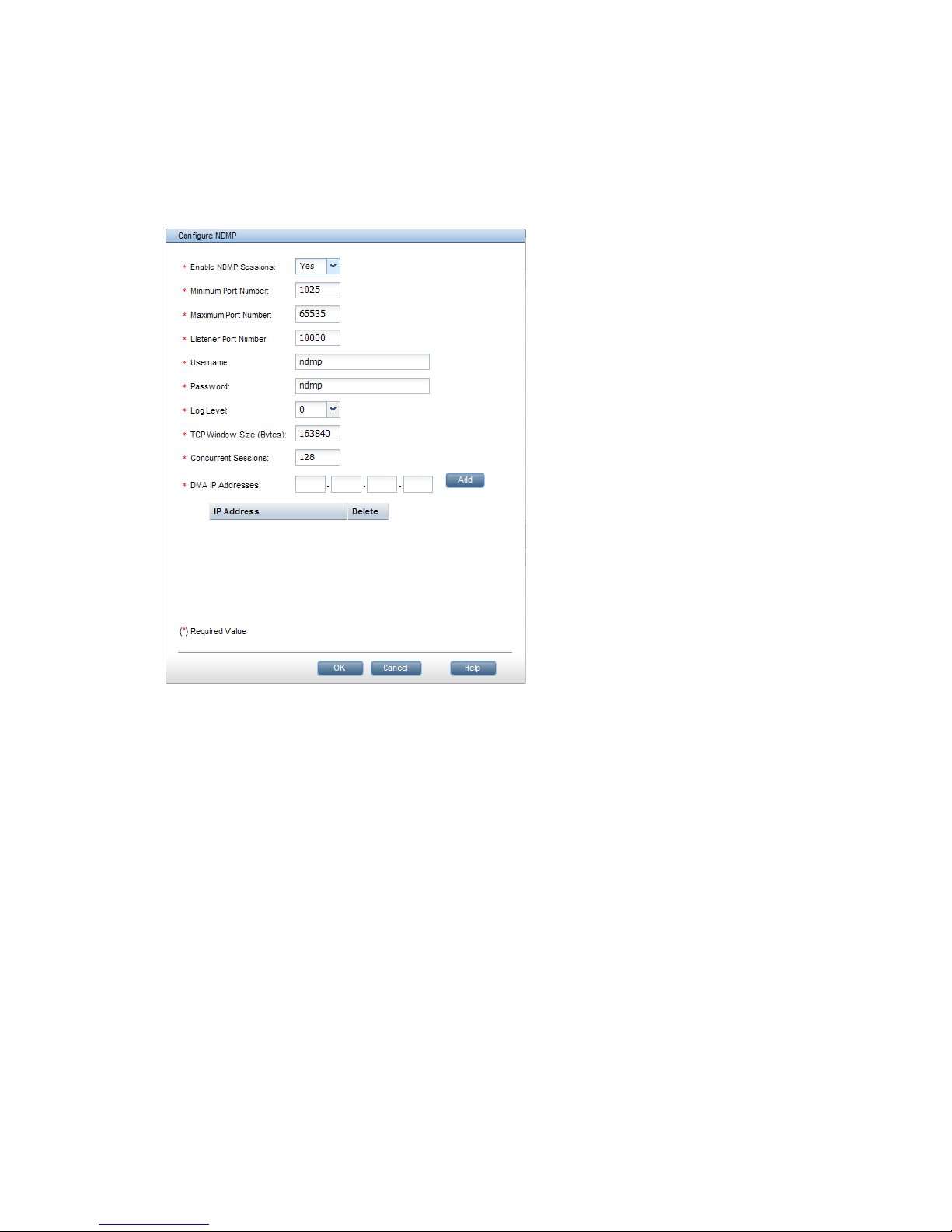
Configuring NDMP parameters on the cluster
Certain NDMP parameters must be configured to enable communications between the DMA and
the NDMP Servers in the cluster. To configure the parameters on the management console GUI,
select Cluster Configuration from the Navigator, and then select NDMP Backup. The NDMP
Configuration Summary shows the default values for the parameters. Click Modify to configure the
parameters for your cluster on the Configure NDMP dialog box. See the online help for a description
of each field.
To configure NDMP parameters from the CLI, use the following command:
ibrix_ndmpconfig –c [-d IP1,IP2,IP3,...] [-m MINPORT] [-x MAXPORT] [-n LISTENPORT]
[-u USERNAME] [-p PASSWORD] [-e {0=disable,1=enable}] –v {0=10}] [-w BYTES]
[-z NUMSESSIONS]
NDMP process management
Normally all NDMP actions are controlled from the DMA. However, if the DMA cannot resolve a
problem or you suspect that the DMA may have incorrect information about the NDMP environment,
take the following actions from the X9000 Software management console GUI or CLI:
• Cancel one or more NDMP sessions on a file serving node. Canceling a session kills all
spawned sessions processes and frees their resources if necessary.
• Reset the NDMP server on one or more file serving nodes. This step kills all spawned session
processes, stops the ndmpd and session monitor daemons, frees all resources held by NDMP,
and restarts the daemons.
Viewing or canceling NDMP sessions
To view information about active NDMP sessions, select Cluster Configuration from the Navigator,
and then select NDMP Backup > Active Sessions. For each session, the Active NDMP Sessions
panel lists the host used for the session, the identifier generated by the backup application, the
status of the session (backing up data, restoring data, or idle), the start time, and the IP address
used by the DMA.
Using NDMP backup applications 43
Page 44
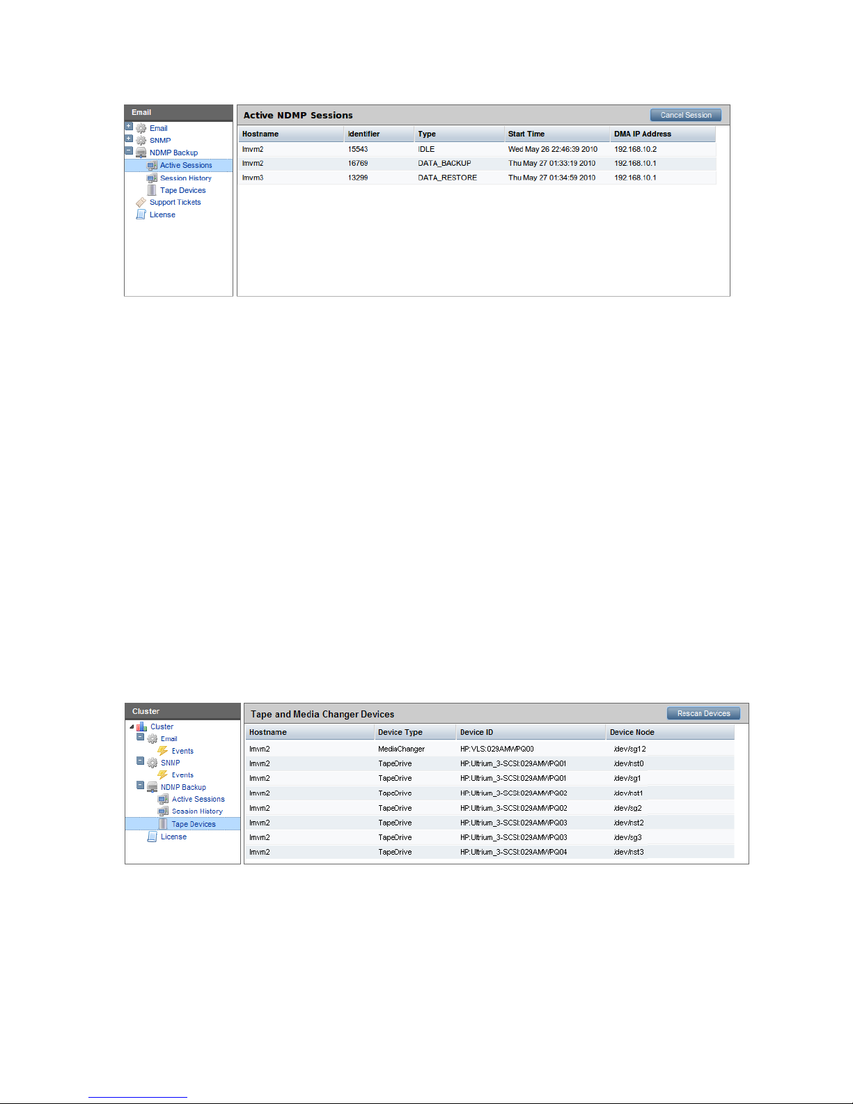
To cancel a session, select that session and click Cancel Session. Canceling a session kills all
spawned sessions processes and frees their resources if necessary.
To see similar information for completed sessions, select NDMP Backup > Session History.
To view active sessions from the CLI, use the following command:
ibrix_ndmpsession –l
To view completed sessions, use the following command. The -t option restricts the history to
sessions occurring on or before the specified date.
ibrix_ndmpsession –l -s [-t YYYY-MM-DD]
To cancel sessions on a specific file serving node, use the following command:
ibrix_ndmpsession –c SESSION1,SESSION2,SESSION3,... –h HOST
Starting, stopping, or restarting an NDMP Server
When a file serving node is booted, the NDMP Server is started automatically. If necessary, you
can use the following command to start, stop, or restart the NDMP Server on one or more file
serving nodes:
ibrix_server –s –t ndmp –c { start | stop | restart} [-h SERVERNAMES]
Viewing or rescanning tape and media changer devices
To view the tape and media changer devices currently configured for backups, select Cluster
Configuration from the Navigator, and then select NDMP Backup > Tape Devices.
If you add a tape or media changer device to the SAN, click Rescan Device to update the list. If
you remove a device and want to delete it from the list, you will need to reboot all of the servers
to which the device is attached.
To view tape and media changer devices from the CLI, use the following command:
ibrix_tape –l
To rescan for devices, use the following command:
ibrix_tape –r
44 Configuring system backups
Page 45

NDMP events
An NDMP Server can generate three types of events: INFO, WARN, and ALERT. These events are
displayed on the management console GUI and can be viewed with the ibrix_event command.
INFO events. These events specify when major NDMP operations start and finish, and also report
progress. For example:
7012:Level 3 backup of /mnt/ibfs7 finished at Sat Nov 7 21:20:58 PST 2009
7013:Total Bytes = 38274665923, Average throughput = 236600391 bytes/sec.
WARN events. These events might indicate an issue with NDMP access, the environment, or NDMP
operations. Be sure to review these events and take any necessary corrective actions. Following
are some examples:
0000:Unauthorized NDMP Client 16.39.40.201 trying to connect
4002:User [joe] md5 mode login failed.
ALERT events. These alerts indicate that an NDMP action has failed. For example:
1102: Cannot start the session_monitor daemon, ndmpd exiting.
7009:Level 6 backup of /mnt/shares/accounts1 failed (writing eod header error).
8001:Restore Failed to read data stream signature.
You can configure the system to send email or SNMP notifications when these types of events
occur.
Using NDMP backup applications 45
Page 46

7 Creating hostgroups for X9000 clients
A hostgroup is a named set of X9000 clients. Hostgroups provide a convenient way to centrally
manage clients using the management console. You can put different sets of clients into hostgroups
and then perform the following operations on all members of the group:
• Create and delete mountpoints
• Mount file systems
• Prefer a network interface
• Tune host parameters
• Set allocation policies
Hostgroups are optional. If you do not choose to set them up, you can mount file systems on clients
and tune host settings and allocation policies on an individual level.
How hostgroups work
In the simplest case, the hostgroups functionality allows you to perform an allowed operation on
all X9000 clients by executing a management console command on the default clients hostgroup
via either the CLI or the GUI. The clients hostgroup includes all X9000 clients configured in the
cluster.
NOTE: The command intention is stored on the management console until the next time the clients
contact the management console. (To force this contact, restart X9000 Software services on the
clients, reboot them, or execute ibrix_lwmount -a or ibrix_lwhost --a.) When contacted,
the management console informs the clients about commands that were executed on hostgroups
to which they belong. The clients then use this information to perform the operation.
You can also use hostgroups to perform different operations on different sets of clients. To do this,
you will need to create a hostgroup tree that includes the necessary hostgroups. You can then
assign the clients manually, or the management console can automatically perform the assignment
when you register an X9000 client, based on the client's cluster subnet. To use automatic assignment,
you will need to create a domain rule that specifies the cluster subnet for the hostgroup.
Creating a hostgroup tree
The clients hostgroup is the root element of the hostgroup tree. Each hostgroup in a tree can
have exactly one parent, and a parent can have multiple children, as shown in the following
diagram). In a hostgroup tree, operations performed on lower-level nodes take precedence over
operations performed on higher-level nodes. This means that you can effectively establish global
client settings that you can override for specific clients.
For example, suppose that you want all clients to be able to mount file system ifs1 and to
implement a set of host tunings denoted as Tuning 1, but you want to override these global settings
for certain hostgroups. To do this, mount ifs1 on the clients hostgroup, ifs2 on hostgroup
A, ifs3 on hostgroup C, and ifs4 on hostgroup D, in any order. Then, set Tuning 1 on the
clients hostgroup and Tuning 2 on hostgroup B. The end result is that all clients in hostgroup B
will mount ifs1 and implement Tuning 2. The clients in hostgroup A will mount ifs2 and implement
Tuning 1. The clients in hostgroups C and D respectively, will mount ifs3 and ifs4 and implement
Tuning 1.
The following diagram shows an example of global and local settings in a hostgroup tree.
46 Creating hostgroups for X9000 clients
Page 47

To set up one level of hostgroups beneath the root, simply create the new hostgroups. You do not
need to declare that the root node is the parent. To set up lower levels of hostgroups, declare a
parent element for hostgroups.
Optionally, you can specify a domain rule for a hostgroup. Use only alphanumeric characters and
the underscore character (_) in hostgroup names.
Do not use a host name as a group name.
To create a hostgroup tree using the CLI:
1. Create the first level of the tree and optionally declare a domain rule for it:
<installdirectory>/bin/ibrix_hostgroup -c -g GROUPNAME [-D DOMAIN]
2. Create all other levels by specifying a parent for the group and optionally a domain rule:
<installdirectory>/bin/ibrix_hostgroup -c -g GROUPNAME [-D DOMAIN] [-p PARENT]
Adding an X9000 client to a hostgroup
You can add an X9000 client to a hostgroup or move a client to a different hostgroup. All clients
belong to the default clients hostgroup.
To add or move a host to a hostgroup, use the ibrix_hostgroup command as follows:
<installdirectory>/bin/ibrix_hostgroup -m -g GROUP -h MEMBER
For example, to add the specified host to the finance group:
<installdirectory>/bin/ibrix_hostgroup -m -g finance -h cl01.hp.com
Adding a domain rule to a hostgroup
To set up automatic hostgroup assignments, define a domain rule for hostgroups. A domain rule
restricts hostgroup membership to clients on a particular cluster subnet. The management console
uses the IP address that you specify for clients when you register them to perform a subnet match
and sorts the clients into hostgroups based on the domain rules.
Setting domain rules on hostgroups provides a convenient way to centrally manage mounting,
tuning, allocation policies, and preferred networks on different subnets of clients. A domain rule
is a subnet IP address that corresponds to a client network. Adding a domain rule to a hostgroup
restricts its members to X9000 clients that are on the specified subnet. You can add a domain rule
at any time.
To add a domain rule to a hostgroup, use the ibrix_hostgroup command as follows:
<installdirectory>/bin/ibrix_hostgroup -a -g GROUPNAME -D DOMAIN
For example, to add the domain rule 192.168 to the finance group:
<installdirectory>/bin/ibrix_hostgroup -a -g finance -D 192.168
Viewing hostgroups
To view hostgroups, use the following command. You can view all hostgroups or a specific
hostgroup.
Adding an X9000 client to a hostgroup 47
Page 48

<installdirectory>/bin/ibrix_hostgroup -l [-g GROUP]
Deleting hostgroups
When you delete a hostgroup, its members are assigned to the parent of the deleted group.
To force the moved X9000 clients to implement the mounts, tunings, network interface preferences,
and allocation policies that have been set on their new hostgroup, either restart X9000 Software
services on the clients (see “Starting and stopping processes” in the system administration guide
for your system) or execute the following commands locally:
• ibrix_lwmount -a to force the client to pick up mounts or allocation policies
• ibrix_lwhost --a to force the client to pick up host tunings
To delete a hostgroup using the CLI:
<installdirectory>/bin/ibrix_hostgroup -d -g GROUPNAME
Other hostgroup operations
Additional hostgroup operations are described in the following locations:
• Creating or deleting a mountpoint, and mounting or unmounting a file system (see “Creating
and mounting file systems” in the HP StorageWorks X9000 File Serving Software File System
User Guide
• Changing host tuning parameters (see “Tuning file serving nodes and X9000 clients” (page 58))
• Preferring a network interface (see “Preferring network interfaces” (page 63))
• Setting allocation policy (see “Using file allocation” in the HP StorageWorks X9000 File
Serving Software File System User Guide)
48 Creating hostgroups for X9000 clients
Page 49

8 Monitoring cluster operations
Monitoring the X9720 Network Storage System status
The X9720 storage monitoring function gathers X9720 system status information and generates
a monitoring report. The X9000 management console displays status information on the dashboard.
This section describes how to the use the CLI to view this information.
Monitoring intervals
The monitoring interval is set by default to 15 minutes (900 seconds). You can change the interval
setting by using the following command to change the <interval_in_seconds> variable:
ibrix_host_tune -C
vendorStorageHardwareMonitoringReportInterval=<interval_in_seconds>
NOTE: The storage monitor will not run if the interval is set to less than 10 minutes.
Viewing storage monitoring output
Use the following command to view the status of the X9720 system:
ibrix_vs -i -n <storagename>
To obtain the storage name, run the ibrix_vs -l command. For example:
# ibrix_vs -l
NAME TYPE IP PROXYIP
----- ---- ---------- ------x303s exds 172.16.1.1
Monitoring the status of file serving nodes
The dashboard on the management console GUI displays information about the operational status
of file serving nodes, including CPU, I/O, and network performance information.
To view status from the CLI, use the ibrix_server -l command. This command provides CPU,
I/O, and network performance information and indicates the operational state of the nodes, as
shown in the following sample output:
<installdirectory>/bin/ibrix_server -l
SERVER_NAME STATE CPU(%) NET_IO(MB/s) DISK_IO(MB/s) BACKUP HA
----------- ------------ ------ ------------ ------------- ------ -node1 Up, HBAsDown 0 0.00 0.00 off
node2 Up, HBAsDown 0 0.00 0.00 off
Monitoring the X9720 Network Storage System status 49
Page 50

File serving nodes can be in one of three operational states: Normal, Alert, or Error. These states
are further broken down into categories that are mostly related to the failover status of the node.
The following table describes the states.
DescriptionState
Up: Operational.Normal
Up-Alert: Server has encountered a condition that has been logged. An event will appear in the Status
tab of the management console GUI, and an email notification may be sent.
Up-InFailover: Server is powered on and visible to the management console, and the management
console is failing over the server’s segments to a standby server.
Up-FailedOver: Server is powered on and visible to the management console, and failover is complete.
Alert
Down-InFailover: Server is powered down or inaccessible to the management console, and the
management console is failing over the server's segments to a standby server.
Down-FailedOver: Server is powered down or inaccessible to the management console, and failover is
complete.
Down: Server is powered down or inaccessible to the management console, and no standby server is
providing access to the server’s segments.
Error
The STATE field also reports the status of monitored NICs and HBAs. If you have multiple HBAs
and NICs and some of them are down, the state will be reported as HBAsDown or NicsDown.
Monitoring cluster events
X9000 Software events are assigned to one of the following categories, based on the level of
severity:
• Alerts. A disruptive evens that can result in loss of access to file system data. For example, a
segment is unavailable or a server is unreachable.
• Warnings. A potentially disruptive condition where file system access is not lost, but if the
situation is not addressed, it can escalate to an alert condition. Some examples are reaching
a very high server CPU utilization or nearing a quota limit.
• Information. An event that changes the cluster (such as creating a segment or mounting a file
system) but occurs under normal or nonthreatening conditions.
Events are written to an events table in the configuration database as they are generated. To
maintain the size of the file, HP recommends that you periodically remove the oldest events. See
“Removing events from the events database table” (page 51) for more information.
You can set up event notifications through email (see “Setting up email notification of cluster events”
(page 37)) or SNMP traps (see “Setting up SNMP notifications” (page 38)).
Viewing events
The dashboard on the management console GUI specifies the number of events that have occurred
in the last 24 hours. Click Events in the GUI Navigator to view a report of the events. You can also
view events that have been reported for specific file systems or servers.
To view events from the CLI, use the following commands:
• View events by type:
<installdirectory>/bin/ibrix_event -q [-e ALERT|WARN|INFO]
• View generated events on a last-in, first-out basis:
50 Monitoring cluster operations
Page 51

<installdirectory>/bin/ibrix_event -l
• View adesignated number of events. The command displays the 100 most recent messages
by default. Use the -n EVENTS_COUNT option to increase or decrease the number of events
displayed.
<installdirectory>/bin/ibrix_event -l [-n EVENTS_COUNT]
The following command displays the 25 most recent events:
<installdirectory>/bin/ibrix_event -l -n 25
Removing events from the events database table
The ibrix_event -p command removes events from the events table, starting with the oldest
events. The default is to remove the oldest seven days of events. To change the number of days,
include the -o DAYS_COUNT option.
<installdirectory>/bin/ibrix_event -p [-o DAYS_COUNT]
Monitoring cluster health
To monitor the functional health of file serving nodes and X9000 clients, execute the ibrix_health
command. This command checks host performance in several functional areas and provides either
a summary or a detailed report of the results.
Health checks
The ibrix_health command runs these health checks on file serving nodes:
• Pings remote file serving nodes that share a network with the test hosts. Remote servers that
are pingable might not be connected to a test host because of a Linux or X9000 Software
issue. Remote servers that are not pingable might be down or have a network problem.
• If test hosts are assigned to be network interface monitors, pings their monitored interfaces to
assess the health of the connection. (For information on network interface monitoring, see
“Using network interface monitoring” (page 31).)
• Determines whether specified hosts can read their physical volumes.
The ibrix_health command runs this health check on both file serving nodes and X9000 clients:
• Determines whether information maps on the tested hosts are consistent with the configuration
database.
If you include the -b option, the command also checks the health of standby servers (if configured).
Health check reports
The summary report provides an overall health check result for all tested file serving nodes and
X9000 clients, followed by individual results. If you include the -b option, the standby servers for
all tested file serving nodes are included when the overall result is determined. The results will be
one of the following:
• Passed. All tested hosts and standby servers passed every health check.
• Failed. One or more tested hosts failed a health check. The health status of standby servers is
not included when this result is calculated.
• Warning. A suboptimal condition that might require your attention was found on one or more
tested hosts or standby servers.
The detailed report consists of the summary report and the following additional data:
• Summary of the test results
• Host information such as operational state, performance data, and version data
Monitoring cluster health 51
Page 52

• Nondefault host tunings
• Results of the health checks
By default, the Result Information field in a detailed report provides data only for health checks
that received a Failed or a Warning result. Optionally, you can expand a detailed report to provide
data about checks that received a Passed result, as well as details about the file system and
segments.
Viewing a summary health report
To view a summary health report, use the ibrix_health -l command:
<installdirectory>/bin/ibrix_health -l [-h HOSTLIST] [-f] [-b]
By default, the command reports on all hosts. To view specific hosts, include the -h HOSTLIST
argument. To view results only for hosts that failed the check, include the -f argument. To include
standby servers in the health check, include the -b argument.
For example, to view a summary report for node i080 and client lab13-116:
<installdirectory>/bin/ibrix_health -l -h i080,lab13-116
Sample output follows:
PASSED
--------------- Host Summary Results ---------------
Host Result Type State Last Update
========= ====== ====== ===== ============================
i080 PASSED Server Up Mon Apr 09 16:45:03 EDT 2007
lab13-116 PASSED Client Up Mon Apr 09 16:07:22 EDT 2007
Viewing a detailed health report
To view a detailed health report, use the ibrix_health -i command:
<installdirectory>/bin/ibrix_health -i -h HOSTLIST [-f] [-s] [-v]
The -f option displays results only for hosts that failed the check. The -s option includes information
about the file system and its segments. The -v option includes details about checks that received
a Passed or Warning result.
The following example shows a detailed health report for file serving node lab13-116:
<installdirectory>/bin/ibrix_health -i -h lab13-116
Overall Health Checker Results - PASSED
=======================================
Host Summary Results
====================
Host Result Type State Last Update
-------- ------ ------ ------------ -----------
lab15-62 PASSED Server Up, HBAsDown Mon Oct 19 14:24:34 EDT 2009
lab15-62 Report
===============
Overall Result
==============
Result Type State Module Up time Last Update
Network Thread Protocol
------ ------ ------------ ------ --------- ----------------------------
------------ ------ --------
PASSED Server Up, HBAsDown Loaded 3267210.0 Mon Oct 19 14:24:34 EDT 2009
99.126.39.72 16 true
CPU Information
===============
Cpu(System,User,Util,Nice) Load(1,3,15 min) Network(Bps) Disk(Bps)
-------------------------- ---------------- ------------ ---------
0, 1, 1, 0 0.73, 0.17, 0.12 1301 9728
Memory Information
==================
Mem Total Mem Free Buffers(KB) Cached(KB) Swap Total(KB) Swap Free(KB)
--------- -------- ----------- ---------- -------------- -------------
1944532 1841548 688 34616 1028152 1028048
Version/OS Information
======================
Fs Version IAD Version OS OS Version Kernel
Version Architecture Processor
52 Monitoring cluster operations
Page 53

----------------- ----------- --------- --------------------------------------------
---------- -------------- ------------ ---------
5.3.468(internal) 5.3.446 GNU/Linux Red Hat Enterprise Linux Server release 5.2
(Tikanga) 2.6.18-92.el5 i386 i686
Remote Hosts
============
Host Type Network Protocol Connection State
-------- ------ ------------ -------- --------------- lab15-61 Server 99.126.39.71 true S_SET S_READY S_SENDHB
lab15-62 Server 99.126.39.72 true S_NEW
Check Results
=============
Check : lab15-62 can ping remote segment server hosts
=====================================================
Check Description Result Result Information
------------------------------- ------ ----------------- Remote server lab15-61 pingable PASSED
Check : Physical volumes are readable
=====================================
Check Description Result Result
Information
--------------------------------------------------------------- ------ -------
---------- Physical volume 0ownQk-vYCm-RziC-OwRU-qStr-C6d5-ESrMIf readable PASSED /dev/sde
Physical volume 1MY7Gk-zb7U-HnnA-D24H-Nxhg-WPmX-ZfUvMb readable PASSED /dev/sdc
Physical volume 7DRzC8-ucwo-p3D2-c89r-nwZD-E1ju-61VMw9 readable PASSED /dev/sda
Physical volume YipmIK-9WFE-tDpV-srtY-PoN7-9m23-r3Z9Gm readable PASSED /dev/sdb
Physical volume ansHXO-0zAL-K058-eEnZ-36ov-Pku2-Bz4WKs readable PASSED /dev/sdi
Physical volume oGt3qi-ybeC-E42f-vLg0-1GIF-My3H-3QhN0n readable PASSED /dev/sdj
Physical volume wzXSW3-2pxY-1ayt-2lkG-4yIH-fMez-QHfbgg readable PASSED /dev/sdd
Check : Iad and Fusion Manager consistent
=========================================
Check Description Result
Result Information
---------------------------------------------------------------------------------
-------------- ------
lab15-61 engine uuid matches on Iad and Fusion Manager PASSED
lab15-61 IP address matches on Iad and Fusion Manager PASSED
lab15-61 network protocol matches on Iad and Fusion Manager PASSED
lab15-61 engine connection state on Iad is up PASSED
lab15-62 engine uuid matches on Iad and Fusion Manager PASSED
lab15-62 IP address matches on Iad and Fusion Manager PASSED
lab15-62 network protocol matches on Iad and Fusion Manager PASSED
lab15-62 engine connection state on Iad is up PASSED
ifs2 file system uuid matches on Iad and Fusion Manager PASSED
ifs2 file system generation matches on Iad and Fusion Manager PASSED
ifs2 file system number segments matches on Iad and Fusion Manager PASSED
ifs2 file system mounted state matches on Iad and Fusion Manager PASSED
Segment owner for segment 1 filesystem ifs2 matches on Iad and Fusion Manager PASSED
Segment owner for segment 2 filesystem ifs2 matches on Iad and Fusion Manager PASSED
ifs1 file system uuid matches on Iad and Fusion Manager PASSED
ifs1 file system generation matches on Iad and Fusion Manager PASSED
ifs1 file system number segments matches on Iad and Fusion Manager PASSED
ifs1 file system mounted state matches on Iad and Fusion Manager PASSED
Segment owner for segment 1 filesystem ifs1 matches on Iad and Fusion Manager PASSED
Superblock owner for segment 1 of filesystem ifs2 on lab15-62 matches on Iad and
Fusion Manager PASSED
Superblock owner for segment 2 of filesystem ifs2 on lab15-62 matches on Iad and
Fusion Manager PASSED
Superblock owner for segment 1 of filesystem ifs1 on lab15-62 matches on Iad and
Fusion Manager PASSED
Monitoring cluster health 53
Page 54

Viewing logs
Logs are provided for the management console, file serving nodes, and X9000 clients. Contact
HP Support for assistance in interpreting log files. You might be asked to tar the logs and email
them to HP.
Viewing and clearing the Integrated Management Log (IML)
The IML logs hardware errors that have occurred on a blade. View or clear events using the
hpasmcli(4) command.
Viewing operating statistics for file serving nodes
Periodically, the file serving nodes report the following statistics to the management console:
• Summary. General operational statistics including CPU usage, disk throughput, network
throughput, and operational state. For information about the operational states, see “Monitoring
the status of file serving nodes” (page 49).
• IO. Aggregate statistics about reads and writes.
• Network. Aggregate statistics about network inputs and outputs.
• Memory. Statistics about available total, free, and swap memory.
• CPU. Statistics about processor and CPU activity.
• NFS. Statistics about NFS client and server activity.
The management console GUI displays most of these statistics on the dashboard. See “Using the
GUI” (page 15) for more information.
To view the statistics from the CLI, use the following command:
<installdirectory>/bin/ibrix_stats -l [-s] [-c] [-m] [-i] [-n] [-f] [-h HOSTLIST]
Use the options to view only certain statistics or to view statistics for specific file serving nodes:
-s Summary statistics
-c CPU statistics
-m Memory statistics
-i I/O statistics
-n Network statistics
-f NFS statistics
-h The file serving nodes to be included in the report
Sample output follows:
---------Summary------------
HOST Status CPU Disk(MB/s) Net(MB/s)
lab12-10.hp.com Up 0 22528 616
---------IO------------
HOST Read(MB/s) Read(IO/s) Read(ms/op) Write(MB/s) Write(IO/s) Write(ms/op)
lab12-10.hp.com 22528 2 5 0 0.00
---------Net------------
HOST In(MB/s) In(IO/s) Out(MB/s) Out(IO/s)
lab12-10.hp.com 261 3 355 2
---------Mem------------
HOST MemTotal(MB) MemFree(MB) SwapTotal(MB) SwapFree(MB)
lab12-10.hp.com 1034616 703672 2031608 2031360
---------CPU-----------
HOST User System Nice Idle IoWait Irq SoftIrq
lab12-10.hp.com 0 0 0 0 97 1 0
---------NFS v3--------
HOST Null Getattr Setattr Lookup Access Readlink Read Write
lab12-10.hp.com 0 0 0 0 0 0 0 0
HOST Create Mkdir Symlink Mknod Remove Rmdir Rename
54 Monitoring cluster operations
Page 55

lab12-10.hp.com 0 0 0 0 0 0 0
HOST Link Readdir Readdirplus Fsstat Fsinfo Pathconf Commit
lab12-10.hp.com 0 0 0 0 0 0 0
Viewing operating statistics for file serving nodes 55
Page 56

9 Maintaining the system
Shutting down the system
To shut down the system completely, first shut down the X9000 software, and then power off the
X9720 hardware.
Shutting down the X9000 Software
Use the following procedure to shut down the X9000 Software. Unless noted otherwise, run the
commands from the dedicated Management Console or from the node hosting the active agile
management console.
1. Disable HA for all file serving nodes:
ibrix_server -m -U
2. If your cluster has an agile management console configuration, place the passive management
console into maintenance mode. Run the following command on the node hosting the passive
management console:
ibrix_fm -m maintenance
3. Stop application services (CIFS, NFS, NDMP backup):
ibrix_server -s -t { cifs | nfs | ndmp } -c stop [-h SERVERLIST]
4. Unmount all file systems:
ibrix_umount -f <fs_name>
To unmount file systems from the management console GUI, select Filesystems >unmount.
5. Unmount all file systems from X9000 clients.
• On Linux X9000 clients, run the following command:
ibrix_lwumount -f <fs_name>
• On Windows X9000 clients, stop all applications accessing the file systems, and then
use the client GUI to unmount the file systems (for example, I: DRIVE). Next, go to Services
and stop the fusion service.
6. Verify that all file systems are unmounted:
ibrix_fs -l
7. Shut down file serving nodes other than the node hosting the active agile management console:
shutdown -t now “now”
8. Shut down the dedicated management console or the node hosting the active agile management
console:
shutdown -t now “now”
Powering off the X9720 system hardware
After shutting down the X9000 Software, power off the X9720 hardware as follows:
1. Power off the 9100c controllers.
2. Power off the 9200cx disk capacity block(s).
3. Power off the file serving nodes.
The cluster is now completely shut down.
56 Maintaining the system
Page 57

Starting up the system
To start a X9720 system, first power on the hardware components, and then start the X900 Software.
Powering on the X9720 system hardware
To power on the X9720 hardware, complete the following steps:
1. Power on the 9100cx disk capacity block(s).
2. Power on the 9100c controllers.
3. Wait for all controllers to report “on” in the 7-segment display.
4. Power on the file serving nodes.
Starting the X9000 Software
To start the X9000 Software, complete the following steps:
1. Power on the dedicated Management Console or the node hosting the active agile management
console.
2. Power on the file serving nodes (*root segment = segment 1; power on owner first, if possible).
3. Monitor the nodes on the management console and wait for them all to report UP in the output
from the following command:
ibrix_server -l
4. Mount file systems and verify their content. Run the following command on the Management
Console or file serving node hosting the active agile management console:
ibrix_mount -f fs_name -m <mountpoint>
On Linux X9000 clients, run the following command:
ibrix_lwmount -f fsname -m <mountpoint>
5. Enable HA on the file serving nodes. Run the following command on the Management Console
or file serving node hosting the active agile management console:
ibrix_server -m
6. On the node hosting the passive agile management console, move the console back to passive
mode:
ibrix_fm -m passive
The X9000 Software is now available, and you can now access your file systems.
Powering file serving nodes on or off
When file serving nodes are connected to properly configured power sources, the nodes can be
powered on or off or can be reset remotely. To prevent interruption of service, set up standbys for
the nodes (see “Identifying standbys for file serving nodes” (page 28)), and then manually fail
them over before powering them off (see “Manually failing over a file serving node” (page 30)).
Remotely powering off a file serving node does not trigger failover.
To power on, power off, or reset a file serving node, use the following command:
<installdirectory>/bin/ibrix_server -P {on|reset|off} -h HOSTNAME
Performing a rolling reboot
The rolling reboot procedure allows you to reboot all file serving nodes in the cluster while the
cluster remains online. Before beginning the procedure, ensure that each file serving node has a
backup node and that X9000 HA is enabled. See “Configuring virtual interfaces for client access”
(page 23) and “Cluster high availability” (page 27) for more information about creating standby
backup pairs, where each server in a pair is the standby for the other.
Starting up the system 57
Page 58

Use one of the following schemes for the reboot:
• Reboot the file serving nodes one-at-a-time.
• Divide the file serving nodes into two groups, with the nodes in the first group having backups
in the second group, and the nodes in the second group having backups in the first group.
You can then reboot one group at-a-time.
To perform the rolling reboot, complete the following steps on each file serving node:
1. Reboot the node directly from Linux. (Do not use the "Power Off" functionality in the
management console, as it does not trigger failover of file serving services.) The node will fail
over to its backup.
2. Wait for the management console to report that the rebooted node is Up.
3. From the management console, failback the node, returning services to the node from its
backup. Run the following command on the backup node:
<installdirectory>/bin/ibrix_server -f -U -h HOSTNAME
HOSTNAME is the name of the node that you just rebooted.
Starting and stopping processes
You can start, stop, and restart processes and can display status for the processes that perform
internal X9000 Software functions. The following commands also control the operation of PostgreSQL
on the machine. The PostgreSQL service is available at /usr/local/ibrix/init/.
To start and stop processes and view process status on the management console, use the following
command:
/etc/init.d/ibrix_fusionmanager [start | stop | restart | status]
To start and stop processes and view process status on a file serving node, use the following
command. In certain situations, a follow-up action is required after stopping, starting, or restarting
a file serving node.
/etc/init.d/ibrix_server [start | stop | restart | status]
To start and stop processes and view process status on an X9000 client, use the following command:
/etc/init.d/ibrix_client [start | stop | restart | status]
Tuning file serving nodes and X9000 clients
The default host tuning settings are adequate for most cluster environments. However, HP Support
may recommend that you change certain file serving node or X9000 client tuning settings to
improve performance.
Host tuning changes are executed immediately for file serving nodes. For X9000 clients, a tuning
intention is stored in the management console. When X9000 Software services start on a client,
the client queries the management console for the host tunings that it should use and then implements
them. If X9000 Software services are already running on a client, you can force the client to query
the management console by executing ibrix_client or ibrix_lwhost --a on the client, or
by rebooting the client.
You can locally override host tunings that have been set on clients by executing the ibrix_lwhost
command.
All management console commands for tuning hosts include the -h HOSTLIST option, which
supplies one or more hostgroups. Setting host tunings on a hostgroup is a convenient way to tune
58 Maintaining the system
Page 59

a set of clients all at once. To set the same host tunings on all clients, specify the clients
hostgroup.
CAUTION: Changing host tuning settings will alter file system performance. Contact HP Support
before changing host tuning settings.
Use the ibrix_host_tune command to list or change host tuning settings:
• To list default values and valid ranges for all permitted host tunings:
<installdirectory>/bin/ibrix_host_tune -L
• To tune host parameters on nodes or hostgroups:
<installdirectory>/bin/ibrix_host_tune -S {-h HOSTLIST|-g GROUPLIST} -o OPTIONLIST
Contact HP Support to obtain the values for OPTIONLIST. List the options as option=value
pairs, separated by commas. To set host tunings on all clients, include the -g clients
option.
• To reset host parameters to their default values on nodes or hostgroups:
<installdirectory>/bin/ibrix_host_tune -U {-h HOSTLIST|-g GROUPLIST} [-n OPTIONS]
To reset all options on all file serving nodes, hostgroups, and X9000 clients, omit the -h
HOSTLIST and -n OPTIONS options. To reset host tunings on all clients, include the -g
clients option.
The values that are restored depend on the values specified for the -h HOSTLIST command:
◦ File serving nodes. The default file serving node host tunings are restored.
◦ X9000 clients. The host tunings that are in effect for the default clients hostgroup are
restored.
◦ Hostgroups. The host tunings that are in effect for the parent of the specified hostgroups
are restored.
• To list host tuning settings on file serving nodes, X9000 clients, and hostgroups, use the
following command. Omit the -h argument to see tunings for all hosts. Omit the -n argument
to see all tunings.
<installdirectory>/bin/ibrix_host_tune -l [-h HOSTLIST] [-n OPTIONS]
• To set the communications protocol on nodes and hostgroups, use the following command.
To set the protocol on all X9000 clients, include the -g clients option.
• <installdirectory>/bin/ibrix_host_tune -p {UDP|TCP} {-h HOSTLIST| -g GROUPLIST}
• To set server threads on file serving nodes, hostgroups, and X9000 clients:
<installdirectory>/bin/ibrix_host_tune -t THREADCOUNT {-h HOSTLIST| -g GROUPLIST}
• To set admin threads on file serving nodes, hostgroups, and X9000 clients, use this command.
To set admin threads on all X9000 clients, include the -g clients option.
<installdirectory>/bin/ibrix_host_tune -a THREADCOUNT {-h HOSTLIST| -g GROUPLIST}
Tuning X9000 clients locally
Linux clients. Use the ibrix_lwhost command to tune host parameters. For example, to set the
communications protocol:
<installdirectory>/bin/ibrix_lwhost --protocol -p {tcp|udp}
To list host tuning parameters that have been changed from their defaults:
<installdirectory>/bin/ibrix_lwhost --list
See the ibrix_lwhost command description in the HP StorageWorks X9000 File Serving
Software CLI Reference Guide for other available options.
Tuning file serving nodes and X9000 clients 59
Page 60

Windows clients. Click the Tune Host tab on the Windows X9000 client GUI. Tunable parameters
include the NIC to prefer (the default is the cluster interface), the communications protocol (UDP
or TCP), and the number of server threads to use. See the online help for the client if necessary.
Migrating segments
To improve cluster performance, segment ownership can be transferred from one host to another
through segment migration. Segment migration transfers segment ownership but it does not move
segments from their physical locations in networked storage systems. Segment ownership is recorded
on the physical segment itself, and the ownership data is part of the metadata that the management
console distributes to file serving nodes and X9000 clients so that they can locate segments.
Migrating specific segments
Use the following command to migrate ownership of the segments in LVLIST on file system FSNAME
to a new host and update the source host:
<installdirectory>/bin/ibrix_fs -m -f FSNAME -s LVLIST -h HOSTNAME [-M] [-F] [-N]
To force the migration, include -M. To skip the source host update during the migration, include
-F. To skip host health checks, include -N.
The following command migrates ownership of ilv2 and ilv3 in file system ifs1 to s1.hp.com:
<installdirectory>/bin/ibrix_fs -m -f ifs1 -s ilv2,ilv3 -h s1.hp.com
Migrating all segments from one host to another
Use the following command to migrate ownership of the segments in file system FSNAME that are
owned by HOSTNAME1 to HOSTNAME2 and update the source host:
<installdirectory>/bin/ibrix_fs -m -f FSNAME -H HOSTNAME1,HOSTNAME2 [-M] [-F] [-N]
For example, to migrate ownership of all segments in file system ifs1 that reside on s1.hp.com
to s2.hp.com:
<installdirectory>/bin/ibrix_fs -m -f ifs1 -H s1.hp.com,s2.hp.com
Removing storage from the cluster
Before removing storage that is used for an X9000 Software file system, you will need to evacuate
the segments (or logical volumes) storing file system data. This procedure moves the data to other
segments in the file system and is transparent to users or applications accessing the file system.
When evacuating a segment, you should be aware of the following restrictions:
• Segment evacuation uses the file system rebalance operation. While the rebalance task is
running, the system will prevents tasks from running on the same file system. Similarly, if
another task is running on the file system, the rebalance task cannot be scheduled until the
first task is complete.
• You cannot evacuate or remove the root segment (segment #1).
• The file system must be quiescent (no active I/O while a segment is being evacuated). Running
this utility while the file system is active may result in data inconsistency or loss.
• If quotas are enabled on the affected file system, the quotas must be disabled during the
rebalance operation.
To evacuate a segment, complete the following steps:
1. Identify the segment residing on the physical volume to be removed. Select Storage from the
Navigator on the management console GUI. Note the file system and segment number on the
affected physical volume. In the following example, physical volume d1 is being retired.
Segment 1 from file system ifs1 uses that physical volume.
60 Maintaining the system
Page 61

2. Locate other segments on the file system that can accommodate the data being evacuated
from the affected segment. Select the file system on the management console GUI and then
select Segments from the lower Navigator. If segments with adequate space are not available,
add segments to the file system. In this example, the data from segment 1 will be evacuated
to segments 2 and 3.
3. If quotas are enabled on the file system, disable them:
ibrix_fs -q -D -f FSNAME
4. Evacuate the segment. Select the file system on the management console GUI and then select
Tasks > Rebalancer from the lower Navigator. Click Start on the Task Summary page to open
the Start Rebalancing dialog, and then open the Advanced tab. In the Source Segments
column, select the segments to evacuate, and in the Destination Segments column, select the
segments to receive the data. (If you do not select destination segments, the data is spread
among the available segments.) Then click Evacuate source segments.
The Task Summary window displays the progress of the rebalance operation and reports any
errors. If you need to stop the operation, click Stop.
5. When the rebalance operation completes, remove the storage from the cluster:
ibrix_replicate -f FSNAME -b EVACUATED_SEGNUM
If you evacuated the root segment (segment 1 by default), include the -F option in the
command.
Removing storage from the cluster 61
Page 62

The segment number associated with the storage is not reused.
6. If quotas were disabled on the file system, unmount the file system and then re-enable quotas
using the following command:
ibrix_fs -q -E -f FSNAME
Then remount the file system.
To evacuate a segment using the CLI, use the ibrix_rebalance -e command, as described
in the HP StorageWorks X9000 File Serving Software CLI Reference Guide.
Maintaining networks
Cluster and user network interfaces
X9000 Software supports the following logical network interfaces:
• Cluster network interface. This network interface carries management console traffic, traffic
between file serving nodes, and traffic between file serving nodes and clients. A cluster can
have only one cluster interface. For backup purposes, each file serving node and management
console can have two cluster NICs.
• User network interface. This network interface carries traffic between file serving nodes and
clients. Multiple user network interfaces are permitted.
The cluster network interface was created for you when your cluster was installed. For clusters with
an agile management console configuration, a virtual interface is used for the cluster network
interface. One or more user network interfaces may also have been created, depending on your
site's requirements. You can add user network interfaces as necessary.
Adding user network interfaces
Although the cluster network can carry traffic between file serving nodes and either NFS/CIFS or
X9000 clients, you may want to create user network interfaces to carry this traffic. If your cluster
must accommodate a mix of NFS/CIFS clients and X9000 clients, or if you need to segregate
client traffic to different networks, you will need one or more user networks. In general, it is better
to assign a user network for NFS/CIFS traffic because the cluster network cannot host the virtual
interfaces (VIFs) required for NFS/CIFS failover. HP recommends that you use a Gigabit Ethernet
port (or faster) for user networks.
When creating user network interfaces for file serving nodes, keep in mind that nodes needing to
communicate for file system coverage or for failover must be on the same network interface. Also,
nodes set up as a failover pair must be connected to the same network interface.
HP recommends that the default network be routed through the base User Network interface.
For a highly available cluster, HP recommends that you put NFS traffic on a dedicated user network
and then set up automated failover for it (see “Setting up automated failover” (page 28)). This
method prevents interruptions to NFS traffic. If the cluster interface is used for NFS traffic and that
interface fails on a file serving node, any NFS clients using the failed interface to access a mounted
file system will lose contact with the file system because they have no knowledge of the cluster and
cannot reroute requests to the standby for the node.
Link aggregation and virtual interfaces
When creating a user network interface, you can use link aggregation to combine physical resources
into a single VIF. VIFs allow you to provide many named paths within the larger physical resource,
each of which can be managed and routed independently, as shown in the following diagram.
See the network interface vendor documentation for any rules or restrictions required for link
aggregation.
62 Maintaining the system
Page 63

Identifying a user network interface for a file serving node
To identify a user network interface for specific file serving nodes, use the ibrix_nic command.
The interface name (IFNAME) can include only alphanumeric characters and underscores, such
as eth1.
<installdirectory>/bin/ibrix_nic -a -n IFNAME -h HOSTLIST
If you are identifying a VIF, add the VIF suffix (:nnnn) to the physical interface name. For example,
the following command identifies virtual interface eth1:1 to physical network interface eth1 on
file serving nodes s1.hp.com and s2.hp.com:
<installdirectory>/bin/ibrix_nic -a -n eth1:1 -h s1.hp.com,s2.hp.com
When you identify a user network interface for a file serving node, the management console queries
the node for its IP address, netmask, and MAC address and imports the values into the configuration
database. You can modify these values later if necessary.
If you identify a VIF, the management console does not automatically query the node. If the VIF
will be used only as a standby network interface in an automated failover setup, the management
console will query the node the first time a network is failed over to the VIF. Otherwise, you must
enter the VIF’s IP address and netmask manually in the configuration database (see “Setting network
interface options in the configuration database” (page 63)). The management console does not
require a MAC address for a VIF.
If you created a user network interface for X9000 client traffic, you will need to prefer the network
for the X9000 clients that will use the network (see “Preferring network interfaces” (page 63)).
Setting network interface options in the configuration database
To make a VIF usable, execute the following command to specify the IP address and netmask for
the VIF. You can also use this command to modify certain ifconfig options for a network.
<installdirectory>/bin/ibrix_nic -c -n IFNAME -h HOSTNAME [-I IPADDR] [-M NETMASK]
[-B BCASTADDR] [-T MTU]
For example, to set netmask 255.255.0.0 and broadcast address 10.0.0.4 for interface eth3 on
file serving node s4.hp.com:
<installdirectory>/bin/ibrix_nic -c -n eth3 -h s4.hp.com -M 255.255.0.0 -B 10.0.0.4
Preferring network interfaces
After creating a user network interface for file serving nodes or X9000 clients, you will need to
prefer the interface for those nodes and clients. (It is not necessary to prefer a network interface
for NFS or CIFS clients, because they can select the correct user network interface at mount time.)
When you prefer a user network interface for traffic from a source host to a destination host, traffic
in the reverse direction remains defaulted to the cluster interface.
Maintaining networks 63
Page 64

A network interface preference is executed immediately on file serving nodes. For X9000 clients,
the preference intention is stored on the management console. When X9000 Software services
start on a client, the client queries the management console for the network interface that has been
preferred for it and then begins to use that interface. If the services are already running on X9000
clients when you prefer a network interface, you can force clients to query the management console
by executing the command ibrix_lwhost --a on the client or by rebooting the client.
Preferring a network interface for a file serving node or X9000 client
The first command prefers a network interface for a File Server Node; the second command prefers
a network interface for a client.
<installdirectory>/bin/ibrix_server -n -h SRCHOST -A DESTHOST/IFNAME
<installdirectory>/bin/ibrix_client -n -h SRCHOST -A DESTHOST/IFNAME
Execute this command once for each destination host that the file serving node or X9000 client
should contact using the specified network interface (IFNAME). For example, to prefer network
interface eth3 for traffic from file serving node s1.hp.com to file serving node s2.hp.com:
<installdirectory>/bin/ibrix_server -n -h s1.hp.com -A s2.hp.com/eth3
Preferring a network interface for a hostgroup
You can prefer an interface for multiple X9000 clients at one time by specifying a hostgroup. To
prefer a user network interface for all X9000 clients, specify the clients hostgroup. After preferring
a network interface for a hostgroup, you can locally override the preference on individual X9000
clients with the command ibrix_lwhost.
To prefer a network interface for a hostgroup, use the following command:
<installdirectory>/bin/ibrix_hostgroup -n -g HOSTGROUP -A DESTHOST/IFNAME
The destination host (DESTHOST) cannot be a hostgroup. For example, to prefer network interface
eth3 for traffic from all X9000 clients (the clients hostgroup) to file serving node s2.hp.com:
<installdirectory>/bin/ibrix_hostgroup -n -g clients -A s2.hp.com/eth3
Unpreferring network interfaces
To return file serving nodes or X9000 clients to the cluster interface, unprefer their preferred network
interface. The first command unprefers a network interface for a file serving node; the second
command unprefers a network interface for a client.
<installdirectory>/bin/ibrix_server -n -h SRCHOST -D DESTHOST
<installdirectory>/bin/ibrix_client -n -h SRCHOST -D DESTHOST
To unprefer a network interface for a hostgroup, use the following command:
<installdirectory>/bin/ibrix_client -n -g HOSTGROUP -A DESTHOST
Making network changes
This section describes how to change IP addresses, change the cluster interface, manage routing
table entries, and delete a network interface.
Changing the IP address for a Linux X9000 client
After changing the IP address for a Linux X9000 client, you must update the X9000 Software
configuration with the new information to ensure that the management console can communicate
with the client. Use the following procedure:
1. Unmount the file system from the client.
2. Change the client’s IP address.
3. Reboot the client or restart the network interface card.
4. Delete the old IP address from the configuration database:
<installdirectory>/bin/ibrix_client -d -h CLIENT
64 Maintaining the system
Page 65

5. Re-register the client with the management console:
<installdirectory>/bin/register_client -p console_IPAddress -c clusterIF –n ClientName
6. Remount the file system on the client.
Changing the IP address for the cluster interface on a dedicated management console
You must change the IP address for the cluster interface on both the file serving nodes and the
management console.
1. If High Availability is enabled, disable it by executing ibrix_server -m -U.
2. Unmount the file system from all file serving nodes, and reboot.
3. On each file serving node, locally change the IP address of the cluster interface.
4. Change the IP address of the cluster interface for each file serving node:
<installdirectory>/bin/ibrix_nic -c -n IFNAME -h HOSTNAME [-I IPADDR]
5. Remount the file system.
6. Re-enable High Availability if necessary by executing ibrix_server -m.
Changing the cluster interface
If you restructure your networks, you might need to change the cluster interface. The following rules
apply when selecting a new cluster interface:
• The management console must be connected to all machines (including standby servers) that
use the cluster network interface. Each file serving node and X9000 client must be connected
to the management console by the same cluster network interface. A Gigabit (or faster) Ethernet
port must be used for the cluster interface.
• X9000 clients must have network connectivity to the file serving nodes that manage their data
and to the standbys for those servers. This traffic can use the cluster network interface or a
user network interface.
To specify a new cluster interface for a cluster with a dedicated management console, use the
following command:
<installdirectory>/bin/ibrix_nic -t -n IFNAME -h HOSTNAME
To specify a new virtual cluster interface for a cluster with an agile management console
configuration, use the following command:
<installdirectory>/bin/ibrix_fm -c <VIF IP address> –d <VIF Device> -n <VIF Netmask>
-v cluster [–I <Local IP address_or_DNS hostname>]
Managing routing table entries
X9000 Software supports one route for each network interface in the system routing table. Entering
a new route for an interface overwrites the existing routing table entry for that interface.
Adding a routing table entry
To add a routing table entry, use the following command:
<installdirectory>/bin/ibrix_nic -r -n IFNAME -h HOSTNAME -A -R ROUTE
The following command adds a route for virtual interface eth2:232 on file serving node
s2.hp.com, sending all traffic through gateway gw.hp.com:
<installdirectory>/bin/ibrix_nic -r -n eth2:232 -h s2.hp.com -A -R gw.hp.com
Deleting a routing table entry
If you delete a routing table entry, it is not replaced with a default entry. A new replacement route
must be added manually. To delete a route, use the following command:
<installdirectory>/bin/ibrix_nic -r -n IFNAME -h HOSTNAME -D
Maintaining networks 65
Page 66

The following command deletes all routing table entries for virtual interface eth0:1 on file serving
node s2.hp.com:
<installdirectory>/bin/ibrix_nic -r -n eth0:1 -h s2.hp.com -D
Deleting a network interface
Before deleting the interface used as the cluster interface on a file serving node, you must assign
a new interface as the cluster interface. See “Changing the cluster interface” (page 65).
To delete a network interface, use the following command:
<installdirectory>/bin/ibrix_nic -d -n IFNAME -h HOSTLIST
The following command deletes interface eth3 from file serving nodes s1.hp.com and
s2.hp.com:
<installdirectory>/bin/ibrix_nic -d -n eth3 -h s1.hp.com,s2.hp.com
Viewing network interface information
Executing the ibrix_nic command with no arguments lists all interfaces on all file serving nodes.
Include the -h option to list interfaces on specific hosts.
<installdirectory>/bin/ibrix_nic -l -h HOSTLIST
The following table describes the fields in the output.
DescriptionField
File serving node for the standby network interface.BACKUP HOST
Standby network interface.BACKUP-IF
File serving node. An asterisk (*) denotes the management console.HOST
Network interface on this file serving node.IFNAME
IP address of this NIC.IP_ADDRESS
Whether monitoring is on for this NIC.LINKMON
MAC address of this NIC.MAC_ADDR
IP address in routing table used by this NIC.ROUTE
Network interface state.STATE
Network type (cluster or user).TYPE
When ibrix_nic is used with the -i option, it reports detailed information about the interfaces.
Use the -h option to limit the output to specific hosts. Use the -n option to view information for a
specific interface.
ibrix_nic -i [-h HOSTLIST] [-n NAME]
66 Maintaining the system
Page 67

10 Migrating to an agile management console configuration
The agile management console configuration provides one active management console and one
passive management console installed on different file serving nodes in the cluster. The migration
procedure configures the current Management Server blade as a host for an agile management
console and installs another instance of the agile management console on a file serving node.
After completing the migration to the agile management console configuration, you can use the
original Management Server blade as follows:
• Use the blade only as a host for the agile management console.
• Convert the blade to a file serving node (to support high availability, the cluster must have an
even number of file serving nodes). The blade can continue to host the agile management
console.
To perform the migration, the X9000 installation code must be available. As delivered, this code
is provided in /tmp/X9720/ibrix. If this directory no longer exists, download the installation
code from the HP support website for your storage system.
IMPORTANT: The migration procedure can be used only on clusters running HP X9000 File
Serving Software 5.4 or later.
Backing up the configuration
Before starting the migration to the agile management console configuration, make a manual
backup of the management console configuration:
ibrix_fm -B
The resulting backup archive is located at /usr/local/ibrix/tmp/fmbackup.zip. Save a
copy of this archive in a safe, remote location, in case recovery is needed.
Performing the migration
Complete the following steps on the blade currently hosting the management console:
1. The agile management console uses a virtual interface (VIF) IP address to enable failover and
prevent any interruptions to file serving nodes and X9000 clients. The existing cluster NIC IP
address becomes the permanent VIF IP address. Identify an unused IP address to use as the
Cluster NIC IP address for the currently running management console.
2. Disable high availability on the server:
ibrix_server –m -U
3. Using ssh, connect to the management console on the user network if possible.
• Edit the /etc/sysconfig/network-scripts/ifcfg-bond0 file. Change the IP
address to the new, unused IP address and also ensure that ONBOOT=Yes.
• If you have preferred X9000 clients over the user bond1 network, edit the /etc/
sysconfig/network-scripts/ifcfg-bond1 file. Change the IP address to another
unused, reserved IP address.
Run one of the following commands:
/etc/init.d/network restart
service network restart
Verify that you can ping the new local IP address.
4. Configure the agile management console:
ibrix_fm -c <cluster_VIF_addr> -d <cluster_VIF_device> –n <cluster_VIF_netmask> -v cluster -I
<local_cluster_IP_addr>
Backing up the configuration 67
Page 68

In the command, <cluster_VIF_addr> is the old cluster IP address for the original
management console and <local_cluster_IP_addr> is the new IP address you acquired.
For example:
[root@x109s1 ~]# ibrix_fm -c 172.16.3.1 -d bond0:1 -n 255.255.248.0 -v cluster
-I 172.16.3.100
Command succeeded!
The original cluster IP address is now configured to the newly created cluster VIF device
(bond0:1).
5. If you created the interface bond1:0 in step 3, now set up the user network VIF, specifying
the user VIF IP address and VIF device used in step 3.
NOTE: This step does not apply to CIFS/NFS clients. If you are not using X9000 clients,
you can skip this step.
Set up the user network VIF:
ibrix_fm -c <user_VIF_IP> -d <user_VIF_device> -n <user_VIF_netmask> -v user
For example:
[root@x109s1 ~]# ibrix_fm -c 10.30.83.1 -d bond1:0 -n 255.255.0.0 -v user
Command succeeded
6. Install the file serving node software on the agile management console node:
ibrix/ibrixinit -ts -C <cluster_interface> -i <agile_cluster_VIF_IP_Addr> —F
For example:
ibrix/ibrixinit -ts -C eth4 -i 172.16.3.100 —F
7. Register the agile management console (also known as agile FM) to the cluster:
ibrix_fm –R <FM hostname> -I <local_cluster_ipaddr>
NOTE: Verify that the local agile management console name is in the /etc/ibrix/
fminstance.xml file. Run the following command:
grep –i current /etc/ibrix/fminstance.xml <property name="currentFmName" value="ib50-86"></property>
8. From the agile management console, verify that the definition was set up correctly:
grep –i vif /etc/ibrix/fusion.xml
The output should be similar to the following:
<property name="fusionManagerVifCheckInterval" value="60"></property>
<property name="vifDevice" value="bond0:0"></property>
<property name="vifNetMask" value="255.255.254.0"></property>
NOTE: If the output is empty, restart the fusionmanager services as in step 9 and then recheck.
9. Restart the fusionmanager services:
/etc/init.d/ibrix_fusionmanager restart
NOTE: It takes approximately 90 seconds for the agile management console to return to
optimal with the agile_cluster_vif device appearing in ifconfig output. Verify that
this device is present in the output.
10. Verify that the agile management console is active:
ibrix_fm –i
For example:
[root@x109s1 ~]# ibrix_fm -i
FusionServer: x109s1 (active, quorum is running)
================================================
Command succeeded!
68 Migrating to an agile management console configuration
Page 69

11. Verify that there is only one management console in this cluster:
ibrix_fm -f
For example:
[root@x109s1 ~]# ibrix_fm -f
NAME IP ADDRESS
------ ---------X109s1 172.16.3.100
Command succeeded!
12. Install a passive agile management console on a second file serving node. In the command,
the -F option forces the overwrite of the new_lvm2_uuid file that was installed with the
X9000 Software. Run the following command on the file serving node:
/ibrix/ibrixinit -tm -C <local_cluster_interface_device>
–v <agile_cluster_VIF_IP> -m <cluster_netmask> -d <cluster_VIF_device> -w 9009
–M passive -F
For example:
[root@x109s3 ibrix]# <install_code_directory>/ibrixinit -tm -C bond0 -v 172.16.3.1
-m 255.255.248.0 -d bond0:0 -V 10.30.83.1 -N 255.255.0.0 -D bond1:0 -w 9009 -M passive -F
NOTE: Verify that the local agile management console name is in the /etc/ibrix/
fminstance.xml file. Run the following command:
grep –i current /etc/ibrix/fminstance.xml <property name="currentFmName" value="ib50-86"></property>
13. From the active management console, verify that both management consoles are in the cluster:
ibrix_fm -f
For example:
[root@x109s3 ibrix]# ibrix_fm -f
NAME IP ADDRESS
------ ---------x109s1 172.16.3.100
x109s3 172.16.3.3
Command succeeded!
14. Verify that the newly installed management console is in passive mode:
ibrix_fm –i
For example:
[root@x109s3 ibrix]# ibrix_fm -i
FusionServer: x109s3 (passive, quorum is running)
=============================
Command succeeded
15. Enable HA on the server hosting the agile management console:
ibrix_server –m
Performing the migration 69
Page 70

NOTE: If iLO was not previously configured on the server, the command will fail with the
following error:
com.ibrix.ias.model.BusinessException: x467s2 is not associated with any power sources
Use the following command to define the iLO parameters into the X9000 cluster database:
ibrix_powersrc -a -t ilo -h HOSTNAME -I IPADDR [-u USERNAME -p PASSWORD]
See the installation guide for more information about configuring iLO.
Converting the original management console node to a file serving node
hosting the agile management console
To convert the original management console node, usually node 1, to a file serving node, complete
the following steps:
1. Place the agile management console on the node into maintenance mode:
ibrix_fm –m maintenance
2. Verify that the management console is in maintenance mode:
ibrix_fm –i
For example:
[root@x109s1 ibrix]# ibrix_fm -i
FusionServer: x109s1 (maintenance, quorum not started)
==================================
Command succeeded!
3. Verify that the passive management console is now the active management console. Run the
ibrix_fm -i command on the file serving node hosting the passive management console
(x109s3 in this example). It may take up to two minutes for the passive management console
to become active.
[root@x109s3 ibrix]# ibrix_fm -i
FusionServer: x109s3 (active, quorum is running)
=============================
Command succeeded!
4. Install the file serving node software on the node:
./ibrixinit -ts -C <cluster_device> -i <cluster VIP> -F
5. Verify that the new file serving node has joined the cluster:
ibrix_server -l
Look for the new file serving node in the output.
6. Rediscover storage on the file serving node:
ibrix_pv -a
7. Set up the file serving node to match the other nodes in the cluster. For example, configure
any user NICs, user and cluster NIC monitors, NIC failover pairs, power, backup servers,
preferred NIC s for X9000 clients, and so on.
70 Migrating to an agile management console configuration
Page 71

11 Upgrading the X9000 Software
This chapter describes how to upgrade to the latest X9000 File Serving Software release. The
management console and all file serving nodes must be upgraded to the new release at the same
time. Note the following:
• Upgrades to the X9000 Software 5.6 release are supported for systems currently running
X9000 Software 5.5.x. If your system is running an earlier release, first upgrade to the 5.5
release, and then upgrade to 5.6.
• The upgrade procedure upgrades the operating system to Red Hat Enterprise Linux 5.5.
• X9000 clients are supported for one version beyond their release. For example, an X9000
5.3.2 client can run with a 5.4 X9000 server, but not with a 5.5 X9000 server.
IMPORTANT: Do not start new remote replication jobs while a cluster upgrade is in progress. If
replication jobs were running before the upgrade started, the jobs will continue to run without
problems after the upgrade completes.
The upgrade to X9000 Software 5.6 is supported only as an offline upgrade. Because it requires
an upgrade of the kernel, the local disk must be reformatted. Clients will experience a short
interruption to administrative and file system access while the system is upgraded.
There are two upgrade procedures available depending on the current installation. If you have an
X9000 Software 5.5 system that was installed through the QR procedure, you can use the automatic
upgrade procedure. If you used an upgrade procedure to install your X9000 Software 5.5 system,
you must use the manual procedure. To determine if your system was installed using the QR
procedure, run the df command. If you see separate file systems mounted on /, /local, /stage,
and /alt, your system was quic-k-stored and you can use the automated upgrade procedure. If
you do not see these mount points, proceed with the manual upgrade process.
• Automatic upgrades. This process uses separate partitioned space on the local disk to save
node-specific configuration information. After each node is upgraded, its configuration is
automatically reapplied.
• Manual upgrades. Before each server upgrade, this process requires that you back up the
node-specific configuration information from the server onto an external device. After the
server is upgraded, you will need to copy and restore the node-specific configuration
information manually.
NOTE: The automatic upgrade procedure can be used only if all nodes in the cluster were
originally installed with the 5.5 release. If you upgraded any nodes in the cluster from the 5.4
release to the 5.5 release, you must use the manual upgrade procedure.
The upgrade takes approximately 45 minutes for X9320 and X9720 systems with a standard
configuration.
Automatic upgrades
All file serving nodes and management consoles must be up when you perform the upgrade. If a
node or management console is not up, the upgrade script will fail. To determine the status of your
cluster nodes, check the dashboard on the GUI or use the ibrix_health command.
NOTE: If you are currently running the 5.5 release with a standard management console and
want to convert to an agile management console configuration, see “Migrating to an agile
management console configuration” (page 67). Migrate to the agile management console first,
and then perform the upgrade.
To upgrade all nodes in the cluster automatically, complete the following steps:
Automatic upgrades 71
Page 72

1. Check the dashboard on the management console GUI to verify that all nodes are up.
2. If file systems are mounted from Windows X9000 clients, unmount them using the X9000
Windows client configuration wizard.
3. Obtain the latest release image from the HP kiosk at http://www.software.hp.com/kiosk (you
will need your HP-provided login credentials).
4. Copy the release .iso file onto the current active management console.
5. Run the following command, specifying the absolute location of the local iso copy as the
argument:
/usr/local/ibrix/setup/upgrade <iso>
The upgrade script performs all necessary upgrade steps on every server in the cluster and
logs progress in the file /usr/local/ibrix/setup/upgrade.log. After the script
completes, each server will be automatically rebooted and will begin installing the latest
software.
6. After the install is complete, the upgrade process automatically restores node-specific
configuration information and the cluster should be running the latest software. If an UPGRADE
FAILED message appears on the active management console, see the specified log file for
details.
7. Remount all previously mounted X9000 Software file systems on Windows X9000 clients using
the X9000 Windows client GUI.
8. Upgrade X9000 clients. See “Upgrading Linux X9000 clients” (page 75) and “Upgrading
Windows X9000 clients” (page 75).
9. If you received a new license from HP, install it as described in the “Licensing” chapter in this
guide.
10. Upgrade firmware on X9720 systems. See “Upgrading firmware on X9720 systems” (page 76).
Manual upgrades
The manual upgrade process requires external storage that will be used to save the cluster
configuration. Each server must be able to access this media directly, not through a network, as
the network configuration is part of the saved configuration. HP recommends that you use a USB
stick or DVD.
NOTE: If you are using a dedicated Management Server and want to convert to an agile
management console configuration, see “Migrating to an agile management console configuration”
(page 67). Complete the migration first, and then perform the upgrade using the agile upgrade
procedure.
NOTE: Be sure to read all instructions before starting the upgrade procedure.
To determine which node is hosting the agile management console configuration, run the ibrix_fm
-i command.
Preparing for the upgrade
Complete the following steps:
1. Ensure that all nodes are up and running.
2. If you are using a dedicated Management Server, skip this step. For an agile configuration,
on all nodes hosting the passive management console, place the management console into
maintenance mode:
<ibrixhome>/bin/ibrix_fm –m maintenance
3. On the active management console node, disable automated failover on all file serving nodes:
<ibrixhome>/bin/ibrix_server -m -U
72 Upgrading the X9000 Software
Page 73

4. Run the following command to verify that automated failover is off. In the output, the HA column
should display off.
<ibrixhome>/bin/ibrix_server -l
5. On the active management console node, stop the NFS and SMB services on all file serving
nodes to prevent NFS and CIFS clients from timing out.
<ibrixhome>/bin/ibrix_server -s -t cifs -c stop
<ibrixhome>/bin/ibrix_server -s -t nfs -c stop
Verify that all likewise services are down on all file serving nodes:
ps –ef | grep likewise
Use kill -9 to kill any likewise services that are still running.
6. If file systems are mounted from a Windows X9000 client, unmount the file systems using the
Windows client GUI.
7. Unmount all X9000 Software file systems:
<ibrixhome>/bin/ibrix_umount -f <fsname>
Saving the node configuration
Complete the following steps on each node, starting with the node hosting the active management
console:
1. Run /usr/local/ibrix/setup/save_cluster_config. This script creates a tgz file
named <hostname>_cluser_config.tgz, which contains a backup of the node
configuration.
2. Save the <hostname>_cluser_config.tgz file, which is located in /tmp, to the external
storage media.
Performing the upgrade
Complete the following steps on each node:
1. Obtain the latest Quick Restore image from the HP kiosk at http://www.software.hp.com/
kiosk (you will need your HP-provided login credentials).
2. Burn the ISO image to a DVD.
3. Insert the Quick Restore DVD into the server DVD-ROM drive.
4. Restart the server to boot from the DVD-ROM.
Manual upgrades 73
Page 74
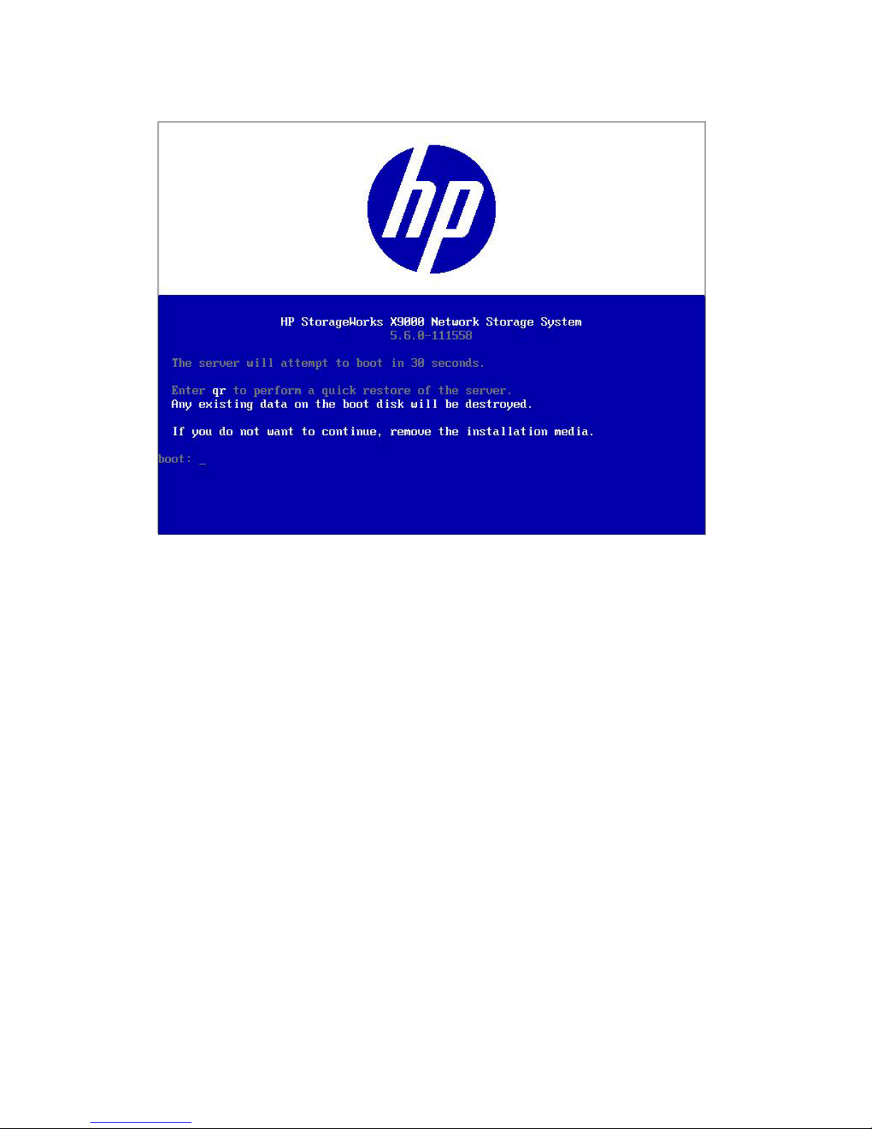
5. When the following screen appears, enter qr to install the X9000 software on the file serving
node.
The server reboots automatically after the software is installed. Remove the DVD from the
DVD-ROM drive.
Restoring the node configuration
Complete the following steps on each node, starting with the previous active management console:
1. Log in to the node. The configuration wizard should pop up. Escape out of the configuration
wizard.
2. Attach the external storage media containing the saved node configuration information.
3. Restore the configuration. Run the following restore script and pass in the tgz file containing
the node's saved configuration information as an argument:
/usr/local/ibrix/setup/restore <saved_config.tgz>
4. Reboot the node.
Completing the upgrade
Complete the following steps:
1. Remount all X9000 Software file systems:
<ibrixhome>/bin/ibrix_mount -f <fsname> -m </mountpoint>
2. Remount all previously mounted X9000 Software file systems on Windows X9000 clients using
the Windows client GUI.
3. If automated failover was enabled before the upgrade, turn it back on from the node hosting
the active management console:
<ibrixhome>/bin/ibrix_server -m
74 Upgrading the X9000 Software
Page 75

4. Confirm that automated failover is enabled:
<ibrixhome>/bin/ibrix_server -l
In the output, HA should display on.
5. From the node hosting the active management console, perform a manual backup of the
upgraded configuration:
<ibrixhome>/bin/ibrix_fm -B
6. Upgrade X9000 clients:
• For Linux clients, see “Upgrading Linux X9000 clients” (page 75).
• For Windows clients, see “Upgrading Windows X9000 clients” (page 75).
7. Verify that all version indicators match for file serving nodes and X9000 clients. Run the
following command from the active management console:
<ibrixhome>/bin/ibrix_version –l
If there is a version mismatch, run the /ibrix/ibrixupgrade -f script again on the
affected node, and then recheck the versions. The installation is successful when all version
indicators match. If you followed all instructions and the version indicators do not match,
contact HP Support.
8. Verify the health of the cluster:
<ibrixhome>/bin/ibrix_health -l
The output should show Passed / on.
9. For an agile configuration, on all nodes hosting the passive management console, return the
management console to passive mode:
<ibrixhome>/bin/ibrix_fm -m passive
10. If you received a new license from HP, install it as described in the “Licensing” chapter in this
document.
11. Upgrade firmware on X9720 systems. See “Upgrading firmware on X9720 systems” (page 76).
Upgrading Linux X9000 clients
Be sure to upgrade the management console and file serving nodes before upgrading Linux X9000
clients. Complete the following steps on each client:
1. Expand the upgrade tarball or mount the upgrade DVD.
2. Run the upgrade script:
./ibrixupgrade -f
The upgrade software automatically stops the necessary services and restarts them when the
upgrade is complete.
3. Execute the following command to verify the client is running X9000 Software:
/etc/init.d/ibrix_client status
IBRIX Filesystem Drivers loaded
IBRIX IAD Server (pid 3208) running...
The IAD service should be running, as shown in the previous sample output. If it is not, contact HP
Support.
Upgrading Windows X9000 clients
Complete the following steps on each client:
Upgrading Linux X9000 clients 75
Page 76

1. Remove the old Windows X9000 client software using the Add or Remove Programs utility in
the Control Panel.
2. Copy the Windows X9000 client MSI file for the upgrade to the machine.
3. Launch the Windows Installer and follow the instructions to complete the upgrade.
4. Register the Windows X9000 client again with the cluster and check the option to Start Service
after Registration.
5. Check Administrative Tools | Services to verify that the X9000 Client service is started.
6. Launch the Windows X9000 client. On the Active Directory Settings tab, click Update to
retrieve the current Active Directory settings.
7. Mount file systems using the X9000 Windows client GUI.
NOTE: If you are using Remote Desktop to perform an upgrade, you must log out and log back
in to see the drive mounted.
Upgrading firmware on X9720 systems
After the cluster is restored, complete the following steps to upgrade the firmware:
1. Copy the update tar file (5_6_exds_firmware_update.tar.gz) to the /tmp directory:
cp /usr/local/ibrix/autocfg/bin/5_6_exds_firmware_update.tar.gz /tmp
2. Change directory to /tmp:
cp /tmp
3. Extract the tar file:
tar –xvf 5_6_exds_firmware_update.tar.gz
4. Change directory to the newly created directory:
cd /5_6_update
5. Open the README file in the directory:
cat README
The README file describes the firmware updates and explains how to install them.
Troubleshooting upgrade issues
If the upgrade does not complete successfully, check the following items. For additional assistance,
contact HP Support.
Automatic upgrade
Check the following:
• If the initial execution of /usr/local/ibrix/setup/upgrade fails, check
/usr/local/ibrix/setup/upgrade.log for errors. It is imperative that all servers are
up and running the X9000 Software before you execute the upgrade script.
• If the install of the new OS fails, power cycle the node. Try rebooting. If the install does not
begin after the reboot, power cycle the machine and select the upgrade line from the grub
boot menu.
• After the upgrade, check /usr/local/ibrix/setup/logs/postupgrade.log for errors
or warnings.
• If configuration restore fails on any node, look at
/usr/local/ibrix/autocfg/logs/appliance.log on that node to determine which
76 Upgrading the X9000 Software
Page 77

feature restore failed. Look at the specific feature log file under /usr/local/ibrix/setup/
logs/ for more detailed information.
To retry the copy of configuration, use the command appropriate for your server:
◦ A dedicated management console:
/usr/local/ibrix/autocfg/bin/ibrixapp upgrade -f
◦ A file serving node:
/usr/local/ibrix/autocfg/bin/ibrixapp upgrade –s
◦ An agile node (a file serving node hosting the agile management console):
/usr/local/ibrix/autocfg/bin/ibrixapp upgrade –f –s
• If the install of the new image succeeds, but the configuration restore fails and you need to
revert the server to the previous install, execute boot_info –r and then reboot the machine.
This step causes the server to boot from the old version (the alternate partition).
• If the public network interface is down and inaccessible for any node, power cycle that node.
Manual upgrade
Check the following:
• If the restore script fails, check /usr/local/ibrix/setup/logs/restore.log for
details.
• If configuration restore fails, look at /usr/local/ibrix/autocfg/logs/appliance.log
to determine which feature restore failed. Look at the specific feature log file under /usr/
local/ibrix/setup/logs/ for more detailed information.
To retry the copy of configuration, use the command appropriate for your server:
◦ A dedicated management console:
/usr/local/ibrix/autocfg/bin/ibrixapp upgrade -f
◦ A file serving node:
/usr/local/ibrix/autocfg/bin/ibrixapp upgrade –s
◦ An agile node (a file serving node hosting the agile management console):
/usr/local/ibrix/autocfg/bin/ibrixapp upgrade –f –s
Troubleshooting upgrade issues 77
Page 78

12 Licensing
This chapter describes how to view your current license terms and how to obtain and install new
X9000 Software product license keys.
NOTE: For MSA2000 G2 licensing (for example, snapshots), see the MSA2000 G2
documentation.
Viewing license terms
The X9000 Software license file is stored in the installation directory on the management console.
To view the license from the management console GUI, select Cluster Configuration in the Navigator
and then select License.
To view the license from the CLI, use the following command:
<installdirectory>/bin/ibrix_license -i
The output reports your current node count and capacity limit. In the output, Segment Server refers
to file serving nodes.
Retrieving a license key
When you purchased this product, you received a License Entitlement Certificate. You will need
information from this certificate to retrieve and enter your license keys.
You can use any of the following methods to request a license key:
• Obtain a license key from http://webware.hp.com.
• Use AutoPass to retrieve and install permanent license keys. See “Using AutoPass to retrieve
and install permanent license keys” (page 78).
• Fax the Password Request Form that came with your License Entitlement Certificate. See the
certificate for fax numbers in your area.
• Call or email the HP Password Center. See the certificate for telephone numbers in your area
or email addresses.
Using AutoPass to retrieve and install permanent license keys
The procedure must be run from a client with JRE 1.5 or later installed and with a desktop manager
running (for example, a Linux-based system running X Windows). The ssh client must also be
installed.
1. On the Linux-based system, run the following command to connect to the Management Console:
ssh -X root@<management_console_IP>
2. When prompted, enter the password for the management console.
3. Launch the AutoPass GUI:
/usr/local/ibrix/bin/fusion-license-manager
4. In the AutoPass GUI, go to Tools, select Configure Proxy, and configure your proxy settings.
5. Click Retrieve/Install License > Key and then retrieve and install your license key.
If the management console does not have an Internet connection, retrieve the license from a
machine that does have a connection, deliver the file with the license to the management
console machine, and then use the AutoPass GUI to import the license.
78 Licensing
Page 79

13 Upgrading the X9720 Network Storage System
hardware
WARNING! Before performing any of the procedures in this chapter, read the important warnings,
precautions, and safety information in “Warnings and precautions” (page 168) and “Regulatory
compliance and safety” (page 172).
Adding new server blades
NOTE: This requires the use of the Quick Restore DVD. See “Recovering the X9720 Network
Storage System” (page 125) for more information.
1. On the front of the blade chassis, in the next available server blade bay, remove the blank.
2. Prepare the server blade for installation.
3. Install the server blade.
Adding new server blades 79
Page 80
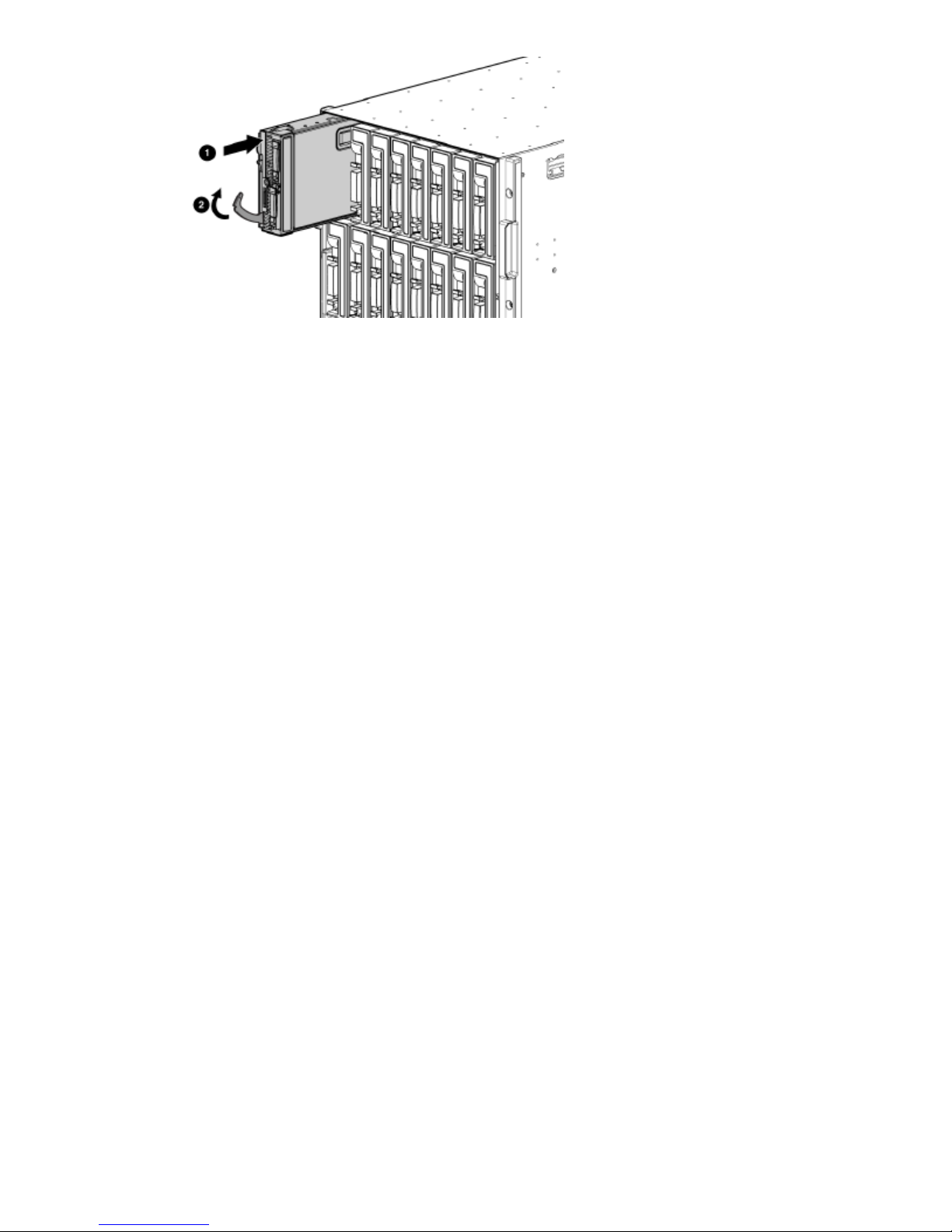
4. Install the software on the server blade. The Quick Restore DVD is used for this purpose. See
“Recovering the X9720 Network Storage System” (page 125) for more information.
5. Set up fail over. For more information, see the HP StorageWorks X9000 File Serving Software
User Guide.
6. Enable high availability (automated failover) by running the following command on server 1:
# ibrix_server –m
7. Discover storage on the server blade:
ibrix_pv -a
8. To enable health monitoring on the server blade, first unregister the vendor storage:
ibrix_vs -d -n <vendor storage name>
Next, re-register the vendor storage. In the command, <sysName> is, for example, x710.
The <hostlist> is a range inside square brackets, such as X710s[2–4]. If the first server
(x710s1 in this example) is hosting the dedicated Management Server, do not include it in
the <hostlist>.
ibrix_vs -r -n <sysName> -t exds 172.16.1.1 -U exds -P <password>
-h <hostlist>
9. If you made any other customizations to other servers, you may need to apply them to the
newly installed server.
80 Upgrading the X9720 Network Storage System hardware
Page 81

Adding capacity blocks
WARNING! To reduce the risk of personal injury or damage to the equipment, follow these
recommendations:
• Use two people to lift, move, and install the HP StorageWorks X9700c component.
• Use an appropriate lifting device to lift, move, and install the HP StorageWorks X9700cx
component.
• Always extend only one component at a time. A cabinet could become unstable if more than
one component is extended for any reason.
CAUTION: When handling system components, equipment may be damaged by electrostatic
discharge (ESD). Use proper anti-static protection at all times:
• Keep the replacement component in the ESD bag until needed.
• Wear an ESD wrist strap grounded to an unpainted surface of the chassis.
• Touch an unpainted surface of the chassis before handling the component.
• Never touch the connector pins.
Carton contents
• HP StorageWorks X9700c, containing 12 disk drives
• HP StorageWorks X9700cx (also known as HP StorageWorks 600 Modular Disk System
[MDS600]), containing 70 disk drives
• Rack mounting hardware
• Two-meter cables (quantity—4)
• Four-meter cables (quantity—2)
Adding capacity blocks 81
Page 82

Where to install the capacity blocks
Base cabinet additional capacity blocks
6 X9700cx 31 X9700c 4
7 TFT monitor and keyboard2 X9700c 3
8 c-Class Blade Enclosure3 X9700c 2
9 X9700cx 24 X9700c 1
10 X9700cx 15 X9700cx 4
Expansion cabinet additional capacity blocks
In an expansion cabinet, you must add capacity blocks in the order shown in the following
illustration. For example, when adding a fifth capacity block to your HP StorageWorks X9720
Network Storage System, the X9700c 5 component goes in slots U31 through 32 (see callout 4),
and the X9700cx 5 goes in slots U1 through U5 (see callout 8).
82 Upgrading the X9720 Network Storage System hardware
Page 83
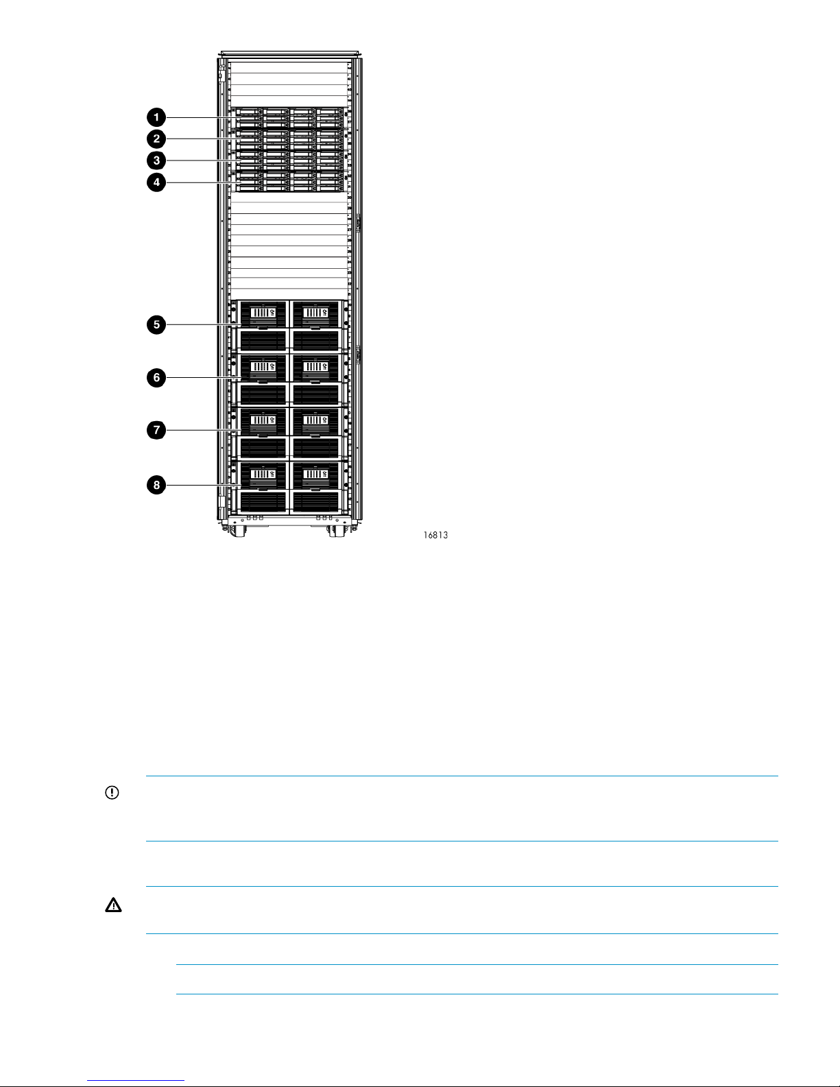
5 X9700cx 81 X9700c 8
6 X9700cx 72 X9700c 7
7 X9700cx 63 X9700c 6
8 X9700cx 54 X9700c 5
Installation procedure
Add the capacity blocks one at a time, until the system contains the maximum it can hold. The
factory pre-provisions the additional capacity blocks with the standard LUN layout and capacity
block settings (for example, rebuild priority). Parity is initialized on all LUNs. The LUNs arrive blank.
IMPORTANT: You can add a capacity block to a new installation or to an existing system. The
existing system can be either online or offline; however, it might be necessary to reboot the blades
to make the new storage visible to the cluster.
Step 1—Install X9700c in the cabinet
WARNING! The X9700c is heavy; therefore, observe local occupational health and safety
requirements and guidelines, such as using two people to lift, move, and install this component.
1. Secure the front end of the rails to the cabinet in the correct location.
NOTE: Identify the left (L) and right (R) rack rails by markings stamped into the sheet metal.
2. Secure the back end of the rails to the cabinet.
Adding capacity blocks 83
Page 84

3. Insert the X9700c into the cabinet.
4. Use the thumbscrews on the front of the chassis to secure it to the cabinet.
Step 2—Install X9700cx in the cabinet
WARNING! Do not remove the disk drives before inserting the X9700cx into the cabinet. The
X9700cx is heavy; therefore, observe local occupational health and safety requirements and
guidelines, such as using a lift for handling this component.
1. Install the rack rails:
a. Align the end of the left rack rail with the rear rack column.
b. Slide the rack rail closed until the end of the rail is locked in place, wrapping behind the
rear rack column.
c. Slide the front end of the rail toward the front column of the rack. When fully seated, the
rack rail will lock into place.
d. Repeat the procedure for the right rack rail.
2. Insert the X9700cx into the cabinet.
WARNING! The X9700cx is very heavy. Use an appropriate lifting device to insert it into
the cabinet.
3. Tighten the thumbscrews to secure the X9700cx to the cabinet.
Step 3—Cable the capacity block
IMPORTANT: Follow the instructions below carefully; correct cabling is critical for the capacity
block to perform properly.
Using the four 2-meter cables, cable the X9700c and the X9700cx, as shown in the following
illustration.
84 Upgrading the X9720 Network Storage System hardware
Page 85

X9700c1
X9700cx primary I/O module (drawer 2)2
X9700cx secondary I/O module (drawer 2)3
X9700cx primary I/O module (drawer 1)4
X9700cx secondary I/O module (drawer 1)5
Adding capacity blocks 85
Page 86

Step 4—Cable the X9700c to SAS switches
Using the two 4-meter cables, cable the X9700c to the SAS switch ports in the c-Class Blade
Enclosure, as shown in the following illustrations for cabling the base or expansion cabinet.
Base cabinet
Callouts 1 through 3 indicate additional X9700c components.
X9700c 41
X9700c 32
X9700c 23
X9700c 14
SAS switch ports 1 through 4 (in interconnect bay 3 of the c-Class Blade Enclosure). Ports 2 through 4 are
used by additional capacity blocks.
5
Reserved for expansion cabinet use.6
SAS switch ports 1 through 4 (in interconnect bay 4 of the c-Class Blade Enclosure). Ports 2 through 4 are
used by additional capacity blocks.
7
Reserved for expansion cabinet use.8
86 Upgrading the X9720 Network Storage System hardware
Page 87
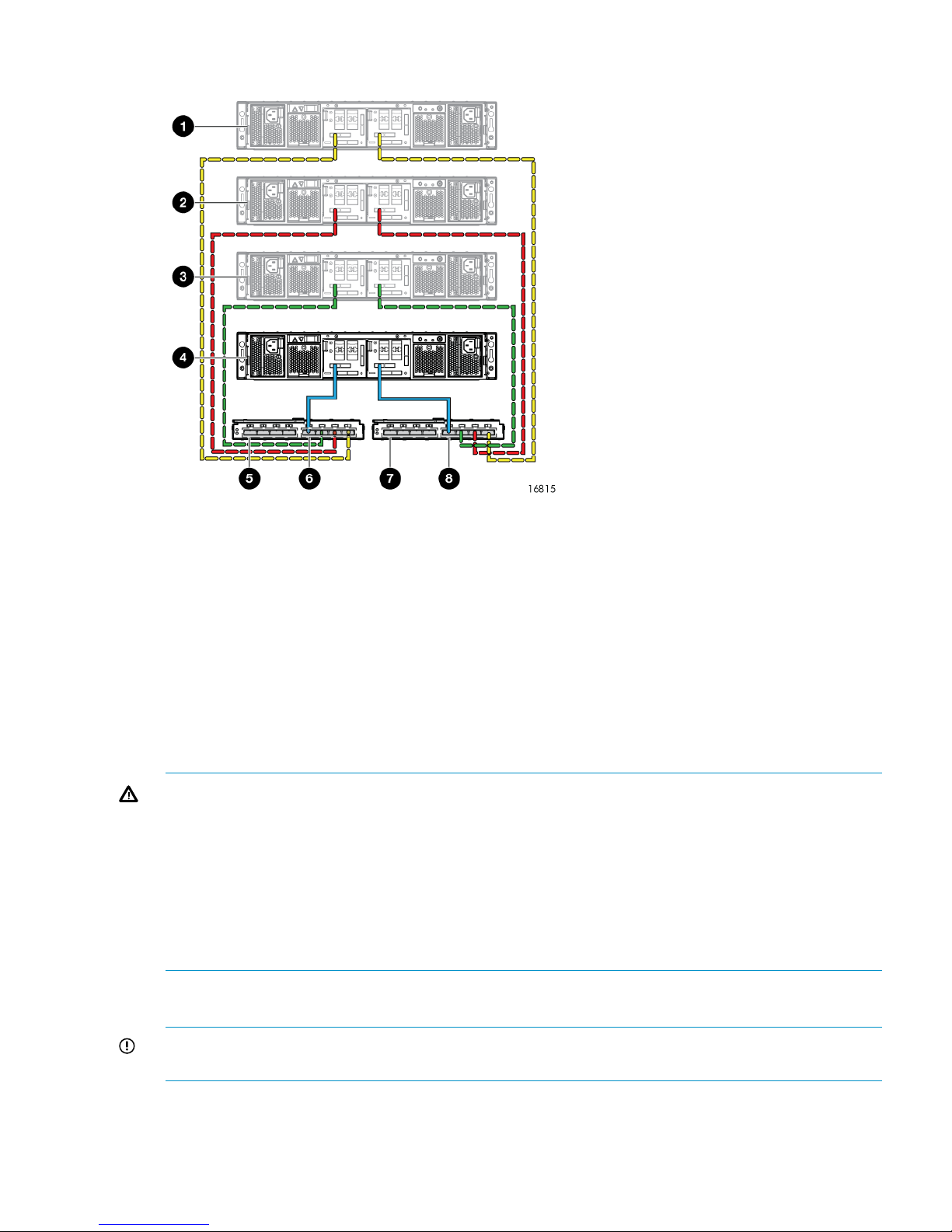
Expansion cabinet
X9700c 81
X9700c 72
X9700c 63
X9700c 54
Used by base cabinet.5
SAS switch ports 5 through 8 (in interconnect bay 3 of the c-Class Blade Enclosure).6
Used by base cabinet.7
SAS switch ports 5 through 8 (in interconnect bay 4 of the c-Class Blade Enclosure).8
Step 5—Connect the power cords
WARNING! To reduce the risk of electric shock or damage to the equipment:
• Do not disable the power cord grounding plug. The grounding plug is an important safety
feature.
• Plug the power cord into a grounded (earthed) electrical outlet that is easily accessible at all
times.
• Do not route the power cord where it can be walked on or pinched by items placed against
it. Pay particular attention to the plug, electrical outlet, and the point where the cord extends
from the storage system.
The X9720 Network Storage System cabinet comes with the power cords tied to the cabinet.
Connect the power cords to the X9700cx first, and then connect the power cords to the X9700c.
IMPORTANT: If your X9720 Network Storage System cabinet contains more than two capacity
blocks, you must connect all the PDUs to a power source.
Step 6—Power on the X9700c and X9700cx components
Power on the X9700cx first, then power on the X9700c.
Adding capacity blocks 87
Page 88

Step 7—Discover the capacity block and validate firmware versions
1. Power on the capacity block by first powering on the X9700cx enclosure followed by the
X9700c enclosure. Wait for the seven-segment display on the rear of the X9700c to read on.
This can take a few minutes.
2. If necessary, update the firmware of the new capacity block. See the HP StorageWorks X9720
Network Storage System Administrator Guide for more information about updating the
firmware.
3. Run the exds_stdiag command on every blade to validate that the new capacity block is
visible and that the correct firmware is installed. See the HP StorageWorks X9720 Network
Storage System Administrator Guide for more information about the command output.
4. To enable the X9720 system to use the new capacity, there must be entries for each LUN in
/dev/cciss on each file serving node. To determine whether the operating system on each
file system node has recognized the new capacity, run this command:
ll /dev/cciss/c0d* | wc -l
The result should include 11 LUNs for each 82-TB capacity block, and 19 LUNs for each
164-TB capacity block.
If the LUNs do not appear, take these steps:
• Run the hpacucli rescan command.
• Check /dev/cciss again for the new LUNs.
• If the LUNs still do not appear, reboot the nodes.
IMPORTANT: If you added the capacity block to an existing system that must remain
online, be sure to use the procedure “Performing a rolling reboot,” described in the HP
StorageWorks X9720 Network Storage System Administrator Guide. If you added the
capacity block to an existing system that is offline, you can reboot all nodes at once.
The capacity block is pre-configured in the factory with data LUNs; however, there are no logical
volumes (segments) on the capacity block. To import the LUNs and create segments, take these
steps:
1. Run the ibrix_pv command to import the LUNs.
2. Run the ibrix_pv -p -h command to verify that the LUNs are visible to all servers.
3. Run the ibrix_fs command to bind the segments and expand (or create) file systems.
For more information about creating or extending file systems, see the HP StorageWorks
X9000 File Serving Software File System User Guide.
Removing server blades
Before permanently removing a server blade, you will need to migrate the server's segments to
other servers. See “Removing storage from the cluster” (page 60) for more information.
Removing capacity blocks
To delete an array:
1. Delete any file systems that use the LUN.
2. Delete the volume groups, logical volumes, and physical volumes associated with the LUN.
3. Disconnect the SAS cables connecting both array controllers to the SAS switches.
CAUTION: Ensure that you remove the correct capacity block. Removing the wrong capacity
block could result in data that is inaccessible.
88 Upgrading the X9720 Network Storage System hardware
Page 89

14 Upgrading firmware
IMPORTANT: The X9720 system is shipped with the correct firmware and drivers. Do not upgrade
firmware or drivers unless the upgrade is recommended by HP Support or is part of an X9720
patch provided on the HP web site.
Firmware update summary
When the X9720 Network Storage System software is first loaded, it automatically updates the
firmware for some components. The following table describes the firmware actions and status for
each component.
Update implications on system
operations
Summary of update processComponent
Requires reboot of server (one at a
time).
Update RPM, then reboot.Server blade BIOS
Requires reboot of server (one at a
time).
Update RPM, then reboot.E200i firmware
Requires reboot of server (one at a
time).
Update RPM, then reboot.E410i
Requires reboot of server (one at a
time).
Update RPM, then reboot.P700m firmware
Requires reboot of server (one at a
time).
Update RPM, then reboot.iLO firmware
Updates while system is running. OA
reboots, but backup OA maintains
operations.
Update RPM, then update using the
OA CLI.
OA firmware
Requires complete system shutdown.Update RPM, then update using the
OA CLI.
Virtual Connect (VC) firmware
Requires complete system shutdown.Update RPM. Run online.X9700c controller firmware HP and
X9700c management (SEP) firmware
Requires complete system shutdown.Update RPM. Run online.X9700cx I/O Controller firmware
Requires complete system shutdown.Update RPM, then update using the
OA CLI.
SAS switch firmware
Requires complete system
shutdown.Note: For individual
out-of-revision drives, return to HP.
Update RPM. Run online.Capacity block disk drive firmware
Locating firmware
Obtain the firmware by one of the following methods:
• HP technical support might send you an updated mxso-firmware RPM. This installs firmware
in /opt/hp/mxso/firmware. This RPM also updates the revision information used by the
exds_stdiag commands. The README.txt file in the directory tells you which file belongs
to which firmware. The files listed in the README.txt file are symlinks to the actual firmware
file. See the following table for a list of the symlinks.
• HP technical support might send you a specific firmware file. Install this in the
/opt/hp/mxso/firmware directory.
• HP technical support might ask you to download a file from www.hp.com. Install this in the
/opt/hp/mxso/firmware directory.
Firmware update summary 89
Page 90

The following table maps firmware files to components. The actual system details may vary.
Symlink name in /opt/hp/mxso/firmwareComponent
sbdisk_scexeDisk drive
exds9100cx_scexeX9700cx I/O controller
exds9100c_scexeX9700c (management (SEP) and X9700c
controller firmware)
oa_fwOA firmware
SASsw_scexeSAS switch
SASsw_mp_fwSAS switch management (Solex)
sbdisk_loc_scexeServer blade local disk
Upgrading Onboard Administrator
1. Download the X9720 Network Storage System mxso-firmware RPM. Install the
mxso-firmware RPM on all servers.
2. Get the IP address of the Onboard Administrator. For example on a system called glory,
look for an entry called glory-mp in /etc/hosts.
You also need a username and password for the Onboard Administrator. You can use the
exds or Administrator username. The password for the Administrator user is located on
a label on OA 1.
3. Run the following command:
# exds_update_oa_firmware
4. The command prompts for IP address, username and password. Use the data from step 2:
HP Onboard Administrator Firmware Flash Utility v1.0.5
Copyright (c) 2009 Hewlett Packard Development Company, L.P.
OA network address:192.172.1.1
Username:exds
Password:****
The command automatically updates both Onboard Administrators, resetting each in turn as
appropriate.
Upgrading all Virtual Connect modules
The Virtual Connect firmware upgrade process updates all Virtual Connect modules at once. During
the update any single NIC (non-bonded) interfaces will lose network connectivity during the update.
NOTE: This procedure assumes that the management network is using a bonded configuration
(that is, bond0 exists). If the system was originally installed with V1.0 software and subsequently
upgraded, the management network might not be bonded. If so, shut down all servers except
server 1 before using this procedure.
1. Download and install the mxso-firmware RPM on all servers.
2. Copy the firmware file (vc_fw) so it can be accessed by a non-root user. This example uses
the ibrix user. However, any other user could be used. You need to know the password of
the chosen user. The following commands copy the file in an appropriate way:
# cp /opt/hp/mxso/firmware/SASsw_mp_fw /home/ibrix
# chown ibrix.ibrix /home/ibrix/vc_fw
90 Upgrading firmware
Page 91

3. Start the FTP server as follows:
# service vsftpd start
4. Log in to the Virtual Connect module domain manager as the ExDS user as shown in the
following example (where glory is the system name):
# ssh exds@glory-vc
5. Ensure that the checkpoint status is valid by running the show domain command as shown
in the following example. Do not proceed if the checkpoint status is not valid.
-> show domain
Domain Name : kudos_vc_domain
Checkpoint Status : Valid
…
6. Run the update firmware command to reload the firmware. The URL is:
ftp://<server-ip>/<path>/vc_fw where <server-ip> is the IP address of the server
where you started the FTP server and <path> is the location of the firmware on the FTP server.
For example, on many systems the first server is 176.16.3.1, in which case the command
could be:
-> update firmware url=ftp://172.16.3.1/home/ibrix/vc_fw
7. Follow any on screen commands to complete the firmware load. The firmware update process
automatically resets all Virtual Connect modules. You could lose network connectivity to the
server when this happens.
8. Exit the Virtual Connect domain manager:
-> exit
9. Check that all Virtual Connect modules have the same firmware and are at the correct minimal
revision.
10. Stop the FTP service:
# service vsftpd stop
Upgrading X9700c controller firmware
This firmware is only delivered in the mxso-firmware RPM.
IMPORTANT: Before performing this procedure, ensure that the X9700c controllers are running
normally. Use the exds_stdiag to verify that the "Path from" from all running servers is "online"
for both X9700c controllers.
To upgrade X9700c controller firmware:
1. Download the RPM.
2. Install on all servers.
3. Use the exds_stdiag command to verify that all storage units are online. In particular, make
sure both controllers in every X9700c chassis are online. If the path to any controller is "none,"
the controller might not be updated.
4. Run the update utility (or utilities) located in /opt/hp/mxso/firmware. If you are updating
several components, run each update utility one at a time. The update utility depends on the
firmware component being updated as follows:
5. Run the following command to update the X9700c controller and X9700c management (SEP)
firmware:
# /opt/hp/mxso/firmware/exds9100c_scexe -s
6. Reboot the first server.
7. Run exds_stdiag to validate that the system is operating normally.
Upgrading X9700c controller firmware 91
Page 92

Upgrading X9700cx I/O module and disk drive firmware
This firmware is only delivered in the mxso-firmware RPM.
IMPORTANT: The update process requires a capacity block to be power cycled. Since this
involves a power cycle of both X9700c controllers or all X9700cx I/O modules, you cannot access
storage during this time. Therefore, a full system shutdown is required.
IMPORTANT: Before performing this procedure, ensure that the X9720 Network Storage System
I/O modules are running normally. Use the exds_stdiag to verify that the "Path from" from all
running servers is "online" for both X9700c controllers.
To upgrade X9700cx I/O module and disk drive firmware:
1. Download the RPM.
2. Install on all servers.
3. Use the exds_stdiag command to verify that all storage units are online. In particular, make
sure both controllers in every X9700c chassis are online. If the path to any controller is "none,"
the controller might not be updated.
4. Shut down all servers except for the first server. Shut down the first server to single user mode.
5. Run the update utility (or utilities) located in /opt/hp/mxso/firmware. If you are updating
several components, run each update utility one at a time. The update utility depends on the
firmware component being updated as follows:
• To update the X9700cx I/O module firmware run the following command:
# /opt/hp/mxso/firmware/exds9100cx_scexe -s
• To update disk driver firmware, run the following command:
# /opt/hp/mxso/firmware/sbdisk_scexe
NOTE: The sbdisk_scexe link is appropriate to firmware supported by the system at first
release. Later models of disk drive might require a different utility.
6. Press the power buttons to power off the X9700c and X9700cx of all capacity blocks in the
system.
7. Disconnect all power cables from all X9700cx enclosures until the LEDs on the rear of the units
extinguish. Reconnect the power cables to the enclosures.
8. Re-apply power to all capacity blocks. Power on the X9700cx first, then the associated X9700c.
The firmware update occurs during reboot so the reboot could take longer than usual (up to
25 minutes). During this time, the seven-segment display will show different codes and the
amber lights of one or both X9700c controllers may come on briefly. This is normal. Wait
until the seven-segment display of all X9700c enclosures goes to the “on” state before
proceeding. If the seven-segment display of an X9700c has not returned to "on" after 25
minutes, power cycle the complete capacity block again.
9. Reboot the first server.
10. Run exds_stdiag to validate that the firmware is updated. If the firmware is not correct,
exds_stdiag prints a "*" (asterisk) character at the start of the line in question.
11. Reboot the other servers.
12. Run exds_stdiag to validate that the system is operating normally.
Upgrading SAS switch module firmware
Complete the following steps:
1. Logon to the Management Server (172.16.3.1).
92 Upgrading firmware
Page 93

2. Start the FTP service:
# service vsftpd start
3. Download the HP 3Gb SAS BL Switch Firmware from the HP Support website or install the
mxso-firmware file onto the Management Server.
4. Copy the firmware file to the /var/ftp/pub directory. For example:
# cp /opt/hp/mxso/firmware/S-2_3_2_13.img /var/ftp/pub
5. ssh to the OA using the exds user:
# ssh 172.16.1.1 —l exds
6. Connect to the switch module in the bay being upgraded (bay 3 or 4):
x123s-ExDS-OA1> connect interconnect <bay number>
7. Log in with the same credentials as the OA.
8. Flash the new firmware. For example:
=> sw local flash file=ftp://172.16.3.1/pub/S-2_3_2_13.img
9. While still logged in to the interconnect, run the reset command.
=> sw local reset hard
continue (y/n)? y
10. While the switch is rebooting, verify that the VSM version number has been updated.
11. Disconnect from the interconnect by pressing Ctrl-Shift-_ (Control, Shift, and underscore keys)
and then enter D for "D)isconnect".
12. Repeat the process if you are upgrading the other bay.
13. Exit from the OA using exit.
14. At the Management Server prompt, run the exds_stdiag command to validate that all
switches are the same and at the correct minimum revision. The output contains text such as:
switch HP.3G.SAS.BL.SWH in 4A fw 2.76
switch HP.3G.SAS.BL.SWH in 3A fw 2.76
switch HP.3G.SAS.BL.SWH in 4B fw 2.76
switch HP.3G.SAS.BL.SWH in 3B fw 2.76
If the firmware version is incorrect, the exds_stdiag command prints a * character at the
beginning of the line.
15. Stop the FTP service:
# service vsftpd stop
16. Log off the Management Server.
Upgrading SAS switch module firmware 93
Page 94

15 Troubleshooting
Managing support tickets
A support ticket includes system and X9000 software information useful for analyzing performance
issues and node terminations. A support ticket is created automatically if a file serving node
terminates unexpectedly. You can also create a ticket manually if your cluster experiences issues
that need to be investigated by HP Support.
The collected information is collated into a tar file and placed in the directory /admin/platform/
diag/support/tickets/ on the active management console. Send this tar file to HP Support
for analysis. The name of the tar file is ticket_<name>/tgz. In the filename, <name> is a
number, for example, ticket_0002.tgz. To view or delete a specific ticket, use the name
assigned to the ticket.
The Support Ticket feature requires that two-way shared SSH keys be configured on all file serving
nodes. For new systems, the keys were configured for you when the cluster was installed. If you
upgraded from a release earlier than 5.4, you need to configure the keys. (See “Configuring
shared ssh keys” (page 95).)
NOTE: When the cluster includes an agile management console configuration, the Support Ticket
information shown on the management console GUI or CLI is in the context of the currently active
management console. If the active management console fails over and the passive management
console becomes active, the existing support ticket information does not move to the newly active
management console. Support Ticket operations are always handled by the currently active
management console and the final output of the operations is stored there.
Creating, viewing, and deleting support tickets
To create a support ticket, select Support Ticket from the GUI Navigator, and then select Create
from the Options list. On the Create Support Ticket dialog box, enter a label to help identify the
ticket. The label is for your information only.
To create a support ticket from the CLI, use the following command:
<ibrixhome>/bin/ibrix_supportticket -c -L <Label>
To view a support ticket on the GUI, select Support Tickets from the Navigator. On the CLI, use
the following command to view all support tickets:
<ibrixhome>/bin/ibrix_supportticket -l
To view details for a specific support ticket, use the following command:
<ibrixhome>/bin/ibrix_supportticket -v -n <Name>
When you no longer need a support ticket, you can delete it. From the GUI, select Support Ticket
from the Navigator. Select the appropriate support ticket, select Delete from the Options menu,
and confirm the operation.
To delete a support ticket from the CLI, use the following command:
<ibrixhome>/bin/ibrix_supportticket -d -n <Name>
94 Troubleshooting
Page 95

Support ticket states
Support tickets are in one of the following states:
DescriptionTicket State
The data collection operation is collecting logs and command output.COLLECTING_LOGS
The data collection operation has completed on all nodes in the cluster.COLLECTED_LOGS
The data collected from each node is being copied to the active management console.CREATING
The ticket was created successfully. The data from each node is available in a tar file in the
/admin/platform/diag/support_tickets/ directory on the active management
console.
CREATED
The ticket was created successfully. Certain nodes were unavailable at the time of copy;
however, the data from the available nodes is available in a tar file in the directory /admin/
platform/diag/support_tickets/ on the active management console.
PARTIALLY_CREATED
The ticket creation operation failed during data collection.OBSOLETE
Updating the ticket database when nodes are added or removed
After adding or removing a Management Server or file serving node, run the
/opt/diagnostics/tools/mxdstool addnodes command on the active management
console. This command registers nodes in the ticket database.
Configuring the support ticket feature
The support ticket feature is typically configured after the X9000 Software installation. To reconfigure
this feature, complete the following steps:
1. Configure password-less SSH on X9000 Management Servers (active/passive) and all file
serving nodes in the cluster, as described in the following section.
2. Verify that the /etc/hosts file on each node contains the hostname entries of all the nodes
in the cluster. If not, add them.
3. Run the /opt/diagnostics/tools/mxdstool addnodes command manually on the
active management console.
NOTE: During the X9000 Software installation, the names of crash dumps in the /var/crash
directory change to include _PROCESSED. For example, 2010-03-08-10:09 changes to
2010-03-08-10:09_PROCESSED.
NOTE: Be sure to monitor the /var/crash directory and remove any unneeded processed
crash dumps.
Configuring shared ssh keys
To configure one-way shared ssh keys on the cluster, complete the following steps:
1. On the management console, run the following commands as root:
# mkdir -p $HOME/.ssh
# chmod 0700 $HOME/.ssh
# ssh-keygen -t dsa -f $HOME/.ssh/id_dsa -P ''
This command creates two files: $HOME/.ssh/id_dsa (private key) and $HOME/.ssh/
id_dsa.pub (public key).
2. On the management console, run the following command for each file serving node:
# ssh-copy-id -i $HOME/.ssh/id_dsa.pub server
3. On the Management Console, test the results by using the ssh command to connect to each
file serving node:
Managing support tickets 95
Page 96

# ssh {hostname for file serving node}
General troubleshooting steps
1. Run the exds_stdiag storage diagnostic utility.
2. Evaluate the results.
3. To report a problem to HP Support, see Escalating issues.
Escalating issues
The X9720 Network Storage System escalate tool produces a report on the state of the system.
When you report a problem to HP technical support, you will always be asked for an escalate
report, so it saves time if you include the report up front.
Run the exds_escalate command as shown in the following example:
[root@glory1 ~]# exds_escalate
The escalate tool needs the root password to perform some actions. Be prepared to enter the root
password when prompted.
There are a few useful options; however, you can usually run without options. The -h option
displays the available options.
It is normal for the escalate command to take a long time (over 20 minutes).
When the escalate tool finishes, it generates a report and stores it in a file such as
/exds_glory1_escalate.tgz.gz. Copy this file to another system and send it to HP Services.
Useful utilities and processes
Accessing the Onboard Administrator (OA) through the network
The OA has a CLI that can be accessed using ssh. The address of the OA is automatically placed
in /etc/hosts. The name is <systemname>-mp. For example, to connect to the OA on a system
called glory, use the following command:
# ssh exds@glory-mp
Access the OA Web-based administration interface
The OA also has a Web-based administration interface. Because the OA's IP address is on the
management network, you cannot access it directly from outside the system. You can use ssh
tunneling to access the OA. For example, using a public domain tool such as putty, you can
configure a local port (for example, 8888) to forward to <systemname>-mp:443 on the remote
server. For example, if the system is called glory, you configure the remote destination as
glory-mp:443. Then log into glory from your desktop. On your desktop, point your browser at
https://localhost:8888. This will connect you to the OA.
On a Linux system, this is equivalent to the following command:
# ssh glory1 -L 8888:glory-mp:443
However, your Linux browser might not be compatible with the OA.
Accessing the Onboard Administrator (OA) through the serial port
Each OA has a serial port. This port can be connected to a terminal concentrator. This provides
remote access to the system if all servers are powered off. All OA commands and functionality is
available through the serial port. To log in, you can use the Administrator or the X9720 Network
Storage System username.
96 Troubleshooting
Page 97

You can also access the OA serial port using the supplied dongle from a blade. This can be useful
if you accidently misconfigure the VC networking so that you cannot access the OA through the
network. You access the serial port as follows:
1. Connect the dongle to the front of one blade.
2. Connect a serial cable from the OA serial port to the serial connector on the dongle.
3. Log in to the server via the TFT keyboard/mouse/monitor.
4. Run minicom as follows:
# Mincom
5. Press Ctrl-A, then p. The Comm Parameters menu is displayed.
6. Select 9600 baud.
7. Press Enter to save.
8. Press Ctrl-A, then m to reinitialize the modem. You are now connected to the serial interface
of the OA.
9. Press Enter.
10. When you are finished, press Ctrl-A, then q to exit minicom.
Accessing the Onboard Administrator (OA) via service port
Each OA has a service port (this is the right-most Ethernet port on the OA). This allows you to use
a laptop to access the OA command line interface. See HP BladeSystem c7000 Enclosure Setup
and Installation Guide for instructions on how to connect a laptop to the service port.
Using hpacucli – Array Configuration Utility (ACU)
The hpacucli command is a command line interface to the X9700c controllers. It can also be
used to configure the E200i and P700m controllers (although HP does not recommend this).
Capacity blocks come pre-configured. However, the hpacucli utility is useful if you need to
configure LUNs. It also allows you to look at the state of arrays. (Also, see the exds_stdiag
utility).
Use the hpacucli command on any server in the system. Do not start multiple copies of hpacucli
(on several different servers) at the same time.
CAUTION: Do not create LUNs unless instructed to do so by HP Support.
The exds_stdiag utility
The exds_stdiag utility probes the SAS storage infrastructure attached to an X9720 Network
Storage System. The utility runs on a single server. Since all the SAS fabric is connected together
it means that exds_stdiag can access all pieces of storage data from the server where it runs.
Having probed the SAS fabric the exds_stdiag utility performs a number of checks including:
• Checks there is more than one path to every disk and LUN.
• Checks that devices are in same order through each path. This detects cabling issues (for
example, reversed cables).
• Checks for missing or bad disks.
• Checks for broken logical disks (RAID sets).
• Checks firmware revisions.
• Reports failed batteries.
The exds_stdiag utility prints a report showing a summary of the storage layout, called the map.
It then analyzes the map and prints information about each check as it is performed. Any line
starting with the asterisk (*) character indicates a problem.
Useful utilities and processes 97
Page 98

The exds_stdiag utility does not access the utility file system, so it can be run even if storage
problems prevent the utility file system from mounting.
Syntax
# exds_stdiag [--raw=<filename>]
The --raw=<filename> option saves the raw data gathered by the tool into the specified file
in a format suitable for offline analysis, for example by HP support personnel.
Following is a typical example of output from this command:
[root@kudos1 ~]# exds_stdiag
ExDS storage diagnostic rev 7336
Storage visible to kudos1 Wed 14 Oct 2009 14:15:33 +0000
node 7930RFCC BL460c.G6
fw I24.20090620
cpus 2 arch Intel
hba 5001438004DEF5D0 P410i in 7930RFCC
fw 2.00
boxes 1 disks 2 luns 1
batteries 0/- cache -
hba PAPWV0F9SXA00S P700m in 7930RFCC
fw 5.74
boxes 0 disks 0 luns 0
batteries 0/- cache switch HP.3G.SAS.BL.SWH in 4A fw 2.72
switch HP.3G.SAS.BL.SWH in 3A fw 2.72
switch HP.3G.SAS.BL.SWH in 4B fw 2.72
switch HP.3G.SAS.BL.SWH in 3B fw 2.72
ctlr P89A40A9SV600X ExDS9100cc in 01/USP7030EKR slot 1
fw 0126.2008120502
boxes 3 disks 80 luns 10
batteries 2/OK cache OK
box 1 ExDS9100c sn USP7030EKR fw 1.56 temp OK fans OK,OK,OK,OK power OK,OK
box 2 ExDS9100cx sn CN881502JE fw 1.28 temp OK fans OK,OK power OK,OK,OK,OK
box 3 ExDS9100cx sn CN881502JE fw 1.28 temp OK fans OK,OK power OK,OK,OK,OK
ctlr P89A40A9SUS0LC ExDS9100cc in 01/USP7030EKR slot 2
fw 0126.2008120502
boxes 3 disks 80 luns 10
batteries 2/OK cache OK
box 1 ExDS9100c sn USP7030EKR fw 1.56 temp OK fans OK,OK,OK,OK power OK,OK
box 2 ExDS9100cx sn CN881502JE fw 1.28 temp OK fans OK,OK power OK,OK,OK,OK
box 3 ExDS9100cx sn CN881502JE fw 1.28 temp OK fans OK,OK power OK,OK,OK,OK
Analysis:
disk problems on USP7030EKR
* box 3 drive [10,15] missing or failed
ctlr firmware problems on USP7030EKR
* 0126.2008120502 (min 0130.2009092901) on ctlr P89A40A9SV600
Network testing tools
You can use the following tools to test the network:
• exds_netdiag—Performs miscellaneous testing of networks in an HP Blade environment
• exds_netperf—Isolates performance issues
98 Troubleshooting
Page 99
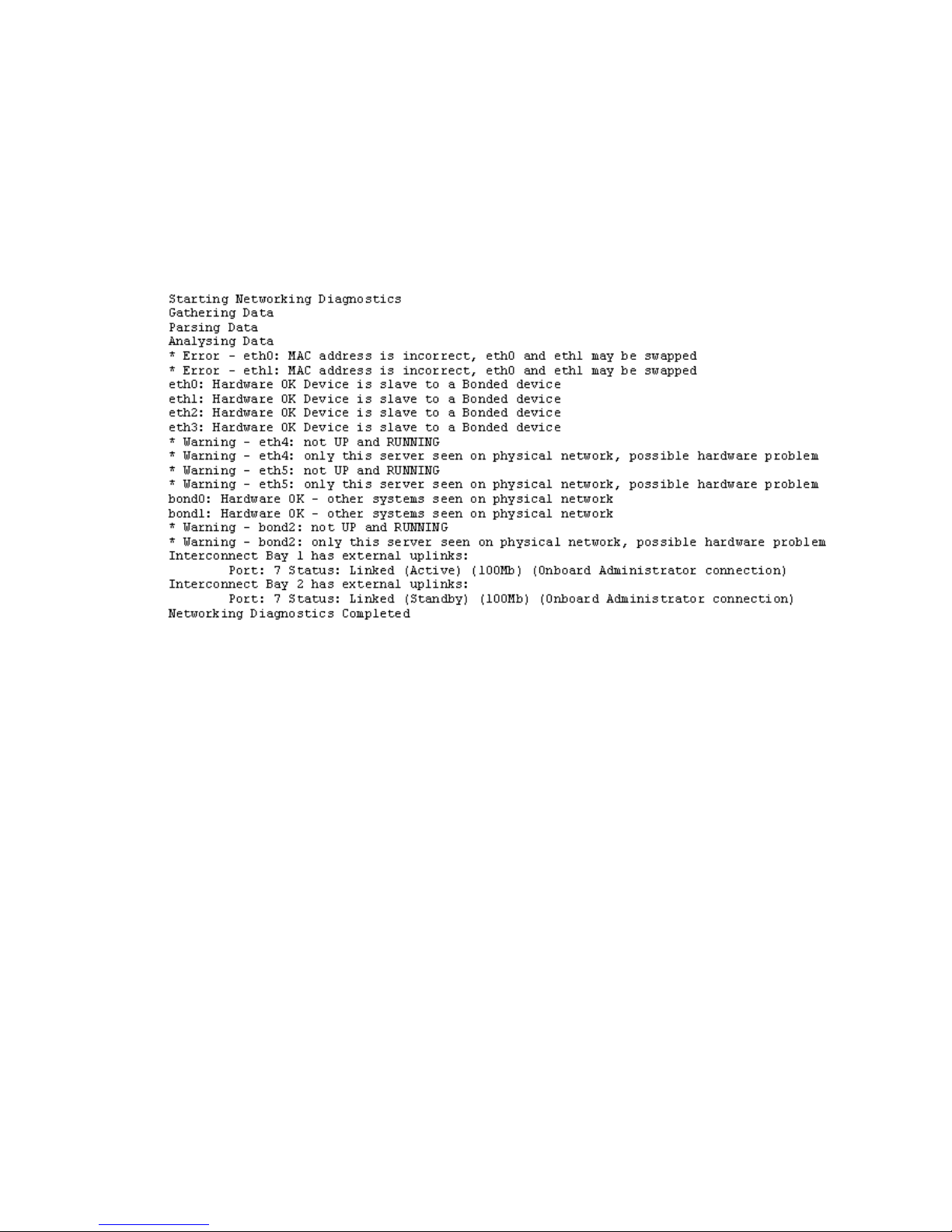
exds_netdiag
The exds_netdiag utility performs tests on and retrieves data from the networking components
in an X9720 Network Storage System. It performs the following functions:
• Reports failed Ethernet Interconnects (failed as reported by the HP Blade Chassis Onboard
Administrator)
• Reports missing, failed, or degraded site uplinks
• Reports missing or failed NICs in server blades
Sample output
exds_netperf
The exds_netperf tool measures network performance. The tool measures performance between
a client system and the X9720 Network Storage System. Run this test when the system is first
installed. Where networks are working correctly, the performance results should match the expected
link rate of the network, that is, for a 1– link, expect about 90 MB/s. You can also run the test at
other times to determine if degradation has occurred.
The exds_netperf utility measures streaming performance in two modes:
• Serial—Streaming I/O is done to each network interface in turn. The host where
exds_netperf is run is the client that is being tested.
• Parallel—Streaming I/O is done on all network interfaces at the same time. This test uses
several clients.
The serial test measures point-to-point performance. The parallel test measures more components
of the network infrastructure and could uncover problems not visible with the serial test. Keep in
mind that overall throughput of the parallel test is probably limited by client’s network interface.
The test is run as follows:
• Copy the contents of /opt/hp/mxso/diags/netperf-2.1.p13 to an x86_64 client host.
• Copy the test scripts to one client from which you will be running the test. The scripts required
are exds_netperf, diags_lib.bash, and nodes_lib.bash from the /opt/hp/mxso/
diags/bin directory.
• Run exds_netserver -s <server_list> to start a receiver for the test on each X9720
Network Storage System server blade, as shown in the following example:
exds_netserver -s glory[1-8]
Useful utilities and processes 99
Page 100

• Read the README.txt file to build for instructions on building exds_netperf and build
and install exds_netperf. Install on every client you plan to use for the test.
• On the client host, run exds_netperf in serial mode against each X9720 Network Storage
System server in turn. For example, if there are two servers whose eth2 addresses are
16.123.123.1 and 16.123.123.2, use the following command:
# exds_netperf --serial --server “16.123.123.1 16.123.123.2”
• On a client host, run exds_netperf in parallel mode, as shown in the following example.
In this example, hosts blue and red are the tested clients (exds_netperf itself could be one
of these hosts or on a third host):
# exds_netperf --parallell \
--server “16.123.123.1,16.123.123.2” \
--clients “red,blue”
Normally, the IP addresses you use are the IP addresses of the host interfaces (eth2, eth3, and so
on).
POST error messages
For an explanation of server error messages, see the "POST error messages and beep codes"
section in the HP ProLiant Servers Troubleshooting Guide at http://www.hp.com/support/manuals.
LUN layout
The LUN layout is presented here in case it's needed for troubleshooting.
For a capacity block with 1 TB HDDs:
• 2x 1 GB LUNs—These were used by the X9100 for membership partitions, and remain in the
X9720 for backwards compatibility. Customers may use them as they see fit, but HP does not
recommend their use for normal data storage, due to performance limitations.
• 1x 100 GB LUN—This is intended for administrative use, such as backups. Bandwidth to these
disks is shared with the 1 GB LUNs above and one of the data LUNs below.
• 8x ~8 TB LUNs—These are intended as the main data storage of the product. Each is supported
by ten disks in a RAID6 configuration; the first LUN shares its disks with the three LUNs
described above.
For capacity blocks with 2 TB HDDs:
• The 1 GB and 100 GB LUNs are the same as above.
• 16x ~8 TB LUNs—These are intended as the main data storage of the product. Each pair of
LUNs is supported by a set of ten disks in a RAID6 configuration; the first pair of LUNs shares
its disks with the three LUNs described above.
X9720 monitoring
The X9720 actively monitors the following components in the system:
• Blade Chassis: Power Supplies, Fans, Networking Modules, SAS Switches, Onboard
Administrator modules.
• Blades: Local hard drives, access to all 9100cc controllers.
• 9100c: Power Supplies, Fans, Hard Drives, 9100cc controllers, and LUN status.
• 9100cx: Power Supplies, Fans, I/O modules, and Hard Drives.
If any of these components fail, an event is generated. Depending on how you have Events
configured, each event will generate an e-mail or SNMP trap. Some components may generate
100 Troubleshooting
 Loading...