

HP StorageWorks X9320 Administrator's Manual

HP StorageWorks
X9320 Network Storage System
Administrator Guide
Abstract
This guide describes tasks related to cluster configuration and monitoring, system upgrade and recovery, hardware component
replacement, and troubleshooting. It does not document X9000 file system features or standard Linux administrative tools and
commands. For information about configuring and using X9000 Software file system features, see the HP StorageWorks X9000
File Serving Software File System User Guide.
This guide is intended for system administrators and technicians who are experienced with installing and administering networks,
and with performing Linux operating and administrative tasks.
HP Part Number: AW542-96006
Published: April 2011
Edition: Seventh

© Copyright 2010 Hewlett-Packard Development Company, L.P.
Confidential computer software. Valid license from HP required for possession, use or copying. Consistent with FAR 12.211 and 12.212, Commercial
Computer Software, Computer Software Documentation, and Technical Data for Commercial Items are licensed to the U.S. Government under
vendor's standard commercial license.
The information contained herein is subject to change without notice. The only warranties for HP products and services are set forth in the express
warranty statements accompanying such products and services. Nothing herein should be construed as constituting an additional warranty. HP shall
not be liable for technical or editorial errors or omissions contained herein.
Acknowledgments
Microsoft® and Windows® are U.S. registered trademarks of Microsoft Corporation.
UNIX® is a registered trademark of The Open Group.
Warranty
WARRANTY STATEMENT: To obtain a copy of the warranty for this product, see the warranty information website:
http://www.hp.com/go/storagewarranty
Revision History
DescriptionSoftware
Version
DateEdition
Initial release of the X9320 Network Storage System administration guide.5.3.1December 2009First
Added network management and support ticket.5.4April 2010Second
Added management console backup, migration to an agile management console
configuration, software upgrade procedures, and system recovery procedures.
5.4.1August 2010Third
Revised upgrade procedure.5.4.1August 2010Fourth
Added information about NDMP backups and configuring virtual interfaces,
and updated cluster procedures.
5.5December 2010Fifth
Updated segment evacuation information.5.5March 2011Sixth
Revised upgrade procedure and updated server information.5.6April 2011Seventh

Contents
1 Product description.....................................................................................9
X9320 Network Storage System features.....................................................................................9
System components...................................................................................................................9
HP X9000 Software features....................................................................................................10
High availability and redundancy.............................................................................................10
2 Getting started.........................................................................................12
Setting up the X9320 Network Storage System...........................................................................12
Installation steps................................................................................................................12
Additional configuration steps.............................................................................................12
Management interfaces...........................................................................................................13
Using the GUI...................................................................................................................13
Customizing the GUI..........................................................................................................16
Adding user accounts for GUI access...................................................................................17
Using the CLI.....................................................................................................................17
Starting the array management software...............................................................................17
X9000 client interfaces.......................................................................................................17
X9000 Software manpages.....................................................................................................18
Changing passwords..............................................................................................................18
Configuring ports for a firewall.................................................................................................18
HP Insight Remote Support software..........................................................................................20
3 Configuring virtual interfaces for client access..............................................21
Network and VIF guidelines.....................................................................................................21
Creating a bonded VIF............................................................................................................21
Configuring standby backup nodes...........................................................................................21
Configuring NIC failover.........................................................................................................22
Configuring automated failover................................................................................................22
Example configuration.............................................................................................................22
Specifying VIFs in the client configuration...................................................................................22
Support for link state monitoring...............................................................................................23
4 Configuring failover..................................................................................24
Agile management consoles....................................................................................................24
Agile management console modes.......................................................................................24
Agile management consoles and failover..............................................................................24
Viewing information about management consoles..................................................................25
Cluster high availability...........................................................................................................25
Failover modes..................................................................................................................25
What happens during a failover..........................................................................................25
Setting up automated failover..............................................................................................26
Identifying standbys for file serving nodes.........................................................................26
Identifying power sources...............................................................................................26
Turning automated failover on and off..............................................................................28
Manually failing over a file serving node..............................................................................28
Failing back a file serving node...........................................................................................29
Using network interface monitoring......................................................................................29
Setting up HBA monitoring..................................................................................................31
Discovering HBAs..........................................................................................................31
Contents 3

Identifying standby-paired HBA ports...............................................................................32
Turning HBA monitoring on or off....................................................................................32
Deleting standby port pairings........................................................................................32
Deleting HBAs from the configuration database.................................................................32
Displaying HBA information............................................................................................32
Checking the High Availability configuration.........................................................................33
5 Configuring cluster event notification...........................................................35
Setting up email notification of cluster events..............................................................................35
Associating events and email addresses................................................................................35
Configuring email notification settings..................................................................................35
Turning email notifications on or off......................................................................................35
Dissociating events and email addresses...............................................................................35
Testing email addresses......................................................................................................36
Viewing email notification settings........................................................................................36
Setting up SNMP notifications..................................................................................................36
Configuring the SNMP agent...............................................................................................37
Configuring trapsink settings................................................................................................37
Associating events and trapsinks..........................................................................................38
Defining views...................................................................................................................38
Configuring groups and users..............................................................................................39
Deleting elements of the SNMP configuration........................................................................39
Listing SNMP configuration information.................................................................................39
6 Configuring system backups.......................................................................40
Backing up the management console configuration.....................................................................40
Using NDMP backup applications............................................................................................40
Configuring NDMP parameters on the cluster........................................................................41
NDMP process management...............................................................................................41
Viewing or canceling NDMP sessions..............................................................................41
Starting, stopping, or restarting an NDMP Server..............................................................42
Viewing or rescanning tape and media changer devices.........................................................42
NDMP events....................................................................................................................43
7 Creating hostgroups for X9000 clients.........................................................44
How hostgroups work..............................................................................................................44
Creating a hostgroup tree........................................................................................................44
Adding an X9000 client to a hostgroup.....................................................................................45
Adding a domain rule to a hostgroup........................................................................................45
Viewing hostgroups.................................................................................................................45
Deleting hostgroups................................................................................................................46
Other hostgroup operations.....................................................................................................46
8 Monitoring cluster operations.....................................................................47
Monitoring the status of file serving nodes..................................................................................47
Monitoring cluster events.........................................................................................................47
Viewing events..................................................................................................................48
Removing events from the events database table....................................................................48
Monitoring cluster health.........................................................................................................48
Health checks....................................................................................................................48
Health check reports..........................................................................................................49
Viewing logs..........................................................................................................................51
4 Contents

Viewing operating statistics for file serving nodes........................................................................51
9 Maintaining the system.............................................................................53
Shutting down the system.........................................................................................................53
Shutting down the X9000 Software......................................................................................53
Powering off the hardware..................................................................................................53
Starting the system..................................................................................................................53
Starting the X9000 Software...............................................................................................53
Powering file serving nodes on or off.........................................................................................54
Performing a rolling reboot......................................................................................................54
Starting and stopping processes...............................................................................................55
Tuning file serving nodes and X9000 clients...............................................................................55
Migrating segments................................................................................................................56
Removing storage from the cluster.............................................................................................57
Maintaining networks..............................................................................................................58
Cluster and user network interfaces......................................................................................58
Adding user network interfaces............................................................................................59
Setting network interface options in the configuration database................................................60
Preferring network interfaces................................................................................................60
Unpreferring network interfaces...........................................................................................61
Making network changes....................................................................................................61
Changing the IP address for a Linux X9000 client..............................................................61
Changing the IP address for the cluster interface on a dedicated management console..........61
Changing the cluster interface.........................................................................................62
Managing routing table entries.......................................................................................62
Deleting a network interface...........................................................................................62
Viewing network interface information..................................................................................62
10 Migrating to an agile management console...............................................64
Backing up the configuration....................................................................................................64
Performing the migration..........................................................................................................64
Removing the dedicated Management Server.............................................................................67
11 Upgrading the X9000 Software................................................................69
Automatic upgrades................................................................................................................69
Manual upgrades...................................................................................................................70
Preparing for the upgrade...................................................................................................70
Saving the node configuration.............................................................................................71
Performing the upgrade......................................................................................................71
Restoring the node configuration..........................................................................................72
Completing the upgrade.....................................................................................................72
Upgrading Linux X9000 clients.................................................................................................73
Upgrading Windows X9000 clients..........................................................................................73
Troubleshooting upgrade issues................................................................................................74
Automatic upgrade............................................................................................................74
Manual upgrade...............................................................................................................75
12 Licensing...............................................................................................76
Viewing license terms..............................................................................................................76
Retrieving a license key...........................................................................................................76
Using AutoPass to retrieve and install permanent license keys........................................................76
Contents 5

13 Upgrading firmware................................................................................77
Upgradable firmware..............................................................................................................77
Downloading MSA2000 G2/G3 firmware................................................................................77
Installing firmware upgrades....................................................................................................77
14 Troubleshooting......................................................................................78
Managing support tickets........................................................................................................78
Creating, viewing, and deleting support tickets......................................................................78
Support ticket states............................................................................................................79
Updating the ticket database when nodes are added or removed............................................79
Configuring the support ticket feature....................................................................................79
Configuring shared ssh keys................................................................................................79
Viewing software version numbers............................................................................................80
Troubleshooting specific issues..................................................................................................80
Software services...............................................................................................................80
Failover............................................................................................................................80
Windows X9000 clients.....................................................................................................81
Synchronizing information on file serving nodes and the configuration database.............................81
15 Replacing components.............................................................................83
Customer replaceable components............................................................................................83
Hot-pluggable and non-hot-pluggable components.................................................................83
Returning the defective component.......................................................................................83
Parts-only warranty service..................................................................................................83
Required tools...................................................................................................................83
Additional documentation...................................................................................................84
Replacing a system board........................................................................................................84
Replacing a NIC adapter........................................................................................................85
16 Recovering a file serving node..................................................................86
Starting the recovery...............................................................................................................86
Configuring a file serving node using the original template..........................................................87
Completing the restore on a file serving node.............................................................................90
Configuring a file serving node manually...................................................................................91
17 Support and other resources...................................................................100
Contacting HP......................................................................................................................100
Related information...............................................................................................................100
HP websites....................................................................................................................101
Rack stability........................................................................................................................101
Customer self repair..............................................................................................................101
Product warranties................................................................................................................101
Subscription service..............................................................................................................102
A System component and cabling diagrams..................................................103
System component diagrams..................................................................................................103
Front view of X9300c array controller or X9300cx 3.5" 12-drive enclosure..............................103
Rear view of X9300c array controller.................................................................................104
Rear view of X9300cx 3.5" 12-drive enclosure.....................................................................104
Front view of file serving node...........................................................................................105
Rear view of file serving node............................................................................................105
6 Contents

Cabling diagrams................................................................................................................108
Cluster network cabling diagram.......................................................................................108
SATA option cabling........................................................................................................109
SAS option cabling..........................................................................................................110
Drive enclosure cabling....................................................................................................111
B Spare parts list.......................................................................................112
1 GbE spare parts................................................................................................................112
10 GbE spare parts..............................................................................................................121
IB spare parts......................................................................................................................129
C Warnings and precautions......................................................................135
Electrostatic discharge information..........................................................................................135
Grounding methods..............................................................................................................135
Equipment symbols...............................................................................................................135
Rack warnings and precautions..............................................................................................136
Device warnings and precautions...........................................................................................136
D Regulatory compliance and safety............................................................138
Regulatory compliance identification numbers..........................................................................138
Federal Communications Commission notice............................................................................138
Class A equipment...........................................................................................................138
Class B equipment...........................................................................................................138
Declaration of conformity for products marked with the FCC logo, United States only................139
Modifications..................................................................................................................139
Cables...........................................................................................................................139
Laser compliance..................................................................................................................139
International notices and statements........................................................................................140
Canadian notice (Avis Canadien)......................................................................................140
Class A equipment......................................................................................................140
Class B equipment......................................................................................................140
European Union notice.....................................................................................................140
BSMI notice....................................................................................................................140
Japanese notice...............................................................................................................140
Korean notice (A&B).........................................................................................................141
Safety.................................................................................................................................141
Battery Replacement notice...............................................................................................141
Taiwan Battery Recycling Notice...................................................................................141
Power cords....................................................................................................................141
Japanese Power Cord notice..............................................................................................142
Electrostatic discharge......................................................................................................142
Preventing electrostatic discharge..................................................................................142
Grounding methods.....................................................................................................142
Waste Electrical and Electronic Equipment directive...................................................................143
Czechoslovakian notice....................................................................................................143
Danish notice..................................................................................................................143
Dutch notice....................................................................................................................143
English notice..................................................................................................................144
Estonian notice................................................................................................................144
Finnish notice..................................................................................................................144
French notice...................................................................................................................144
German notice................................................................................................................145
Greek notice...................................................................................................................145
Contents 7

Hungarian notice.............................................................................................................145
Italian notice...................................................................................................................145
Latvian notice..................................................................................................................146
Lithuanian notice..............................................................................................................146
Polish notice....................................................................................................................146
Portuguese notice.............................................................................................................146
Slovakian notice..............................................................................................................147
Slovenian notice..............................................................................................................147
Spanish notice.................................................................................................................147
Swedish notice................................................................................................................147
Glossary..................................................................................................148
Index.......................................................................................................150
8 Contents
1 Product description
The HP StorageWorks X9320 Network Storage System is a highly available, scale-out storage
solution for file data workloads. The system combines HP X9000 File Serving Software with HP
server and storage hardware to create an expansible cluster of file serving nodes.
X9320 Network Storage System features
The X9320 Network Storage System provides the following features:
• Segmented, scalable file system under a single namespace
• NFS, CIFS, FTP, and HTTP support for accessing file system data
• Centralized CLI and GUI cluster management
• Policy management
• Continuous remote replication
• Dual redundant paths to all storage components
• Gigabytes-per-second throughput
IMPORTANT: It is important to keep regular backups of the cluster configuration. See “Backing
up the management console configuration” (page 40) for more information.
System components
The HP StorageWorks X9320 Network Storage System is available in in a wide range of capacity
and performance configurations.two configurations. Components in the system differ depending
on the chosen configuration.
Common system components include:
• Two HP StorageWorks file serving nodes
• Optional Management Server
• Two or four HP StorageWorks X9300c storage controllers
• Four or eight HP StorageWorks X9300cx disk enclosures (48 or 96 hard drives)
X9320 Network Storage System features 9

• Optional HP StorageWorks X9300 Network Storage System Base Rack. The rack includes
the following:
◦ Keyboard, video, and mouse (KVM)
◦ Optional network switch
• Pre-installed software, including the following:
Red Hat Linux operating system◦
◦ X9000 File Serving Software
◦ Integrated Lights-Out 2 (iLO 2) remote management software
Front-end connectivity can be one of the following:
• 10GbE network
• 1GbE network
• IB network
See “System component and cabling diagrams” (page 103) for system component and cabling
diagrams.
HP X9000 Software features
HP X9000 Software is a scale-out, network-attached storage solution composed of a parallel file
system for clusters, an integrated volume manager, high-availability features such as automatic
failover of multiple components, and a centralized management interface. X9000 Software can
be deployed in environments scaling to thousands of nodes.
Based on a Segmented File System architecture, X9000 Software enables enterprises to integrate
I/O and storage systems into a single clustered environment that can be shared across multiple
applications and managed from a single central management console.
X9000 Software is designed to operate with high-performance computing applications that require
high I/O bandwidth, high IOPS throughput, and scalable configurations. Examples of these
applications include Internet streaming, rich media streaming, data mining, web search,
manufacturing, financial modeling, life sciences modeling, and seismic processing.
Some of the key features and benefits are as follows:
• Scalable configuration. You can add servers to scale performance and add storage devices
to scale capacity.
• Single namespace. All directories and files are contained in the same namespace.
• Multiple environments. Operates in both the SAN and DAS environments.
• High availability. The high-availability software protects servers.
• Tuning capability. The system can be tuned for large or small-block I/O.
• Flexible configuration. Segments can be migrated dynamically for rebalancing and data
tiering.
High availability and redundancy
The segmented architecture is the basis for fault resilience—loss of access to one or more segments
does not render the entire file system inaccessible. Individual segments can be taken offline
temporarily for maintenance operations and then returned to the file system.
10 Product description

To ensure continuous data access, X9000 Software provides manual and automated failover
protection at various points:
• Server. A failed node is powered down and a designated standby server assumes all of its
segment management duties.
• Segment. Ownership of each segment on a failed node is transferred to a designated standby
server.
• Network interface. The IP address of a failed network interface is transferred to a standby
network interface until the original network interface is operational again.
• Storage connection. For servers with HBA-protected Fibre Channel access, failure of the HBA
triggers failover of the node to a designated standby server.
High availability and redundancy 11

2 Getting started
IMPORTANT: Do not modify any parameters of the operating system or kernel, or update any
part of the X9320 Network Storage System unless instructed to do so by HP; otherwise, the X9320
Network Storage System could fail to operate properly.
Setting up the X9320 Network Storage System
Installation steps
An HP service specialist sets up the system at your site, including the following tasks:
• Remove the product from the shipping cartons that you have placed in the location where the
product will be installed, confirm the contents of each carton against the list of included items
and check for any physical damage to the exterior of the product, and connect the product
to the power and network provided by you.
• Review your server, network, and storage environment relevant to the HP Enterprise NAS
product implementation to validate that prerequisites have been met.
• Validate that your file system performance, availability, and manageability requirements have
not changed since the service planning phase. Finalize the HP Enterprise NAS product
implementation plan and software configuration.
• Implement the documented and agreed-upon configuration based on the information you
provided on the pre-delivery checklist.
• Document configuration details.
Additional configuration steps
When your system is up and running, you can perform any additional configuration of your cluster
and file systems. The management console GUI and CLI are used to perform most operations.
(Some of the features described here might have been configured for you as part of the system
installation.)
Cluster. Configure the following as needed:
• Virtual interfaces for client access.
• Failover for file serving nodes, network interfaces, and HBAs.
• Cluster event notification through email or SNMP.
• Management console backups.
• NDMP backups.
These cluster features are described later in this guide.
File systems. Set up the following features as needed:
• Additional file systems. Optionally, configure data tiering on the file systems to move files to
specific tiers based on file attributes.
• NFS, CIFS, FTP, or HTTP. Configure the methods you will use to access file system data.
• Quotas. Configure user, group, and directory tree quotas as needed.
• Remote replication. Use this feature to replicate changes in a source file system on one cluster
to a target file system on either the same cluster or a second cluster.
12 Getting started

• Snapshots. Use this feature to capture a point-in-time copy of a file system.
• File allocation. Use this feature to specify the manner in which segments are selected for storing
new files and directories.
For more information about these file system features, see the HP StorageWorks File Serving
Software File System User Guide.
Management interfaces
Cluster operations are managed through the X9000 Software management console, which provides
both a GUI and a CLI. Most operations can be performed from either the GUI or the CLI. However,
the following operations can be performed only from the CLI:
• SNMP configuration (ibrix_snmpagent, ibrix_snmpgroup, ibrix_snmptrap,
ibrix_snmpuser, ibrix_snmpview)
• Health checks (ibrix_haconfig, ibrix_health, ibrix_healthconfig)
• Raw storage management (ibrix_pv, ibrix_vg, ibrix_lv)
• Management console operations (ibrix_fm) and management console tuning
(ibrix_fm_tune)
• File system checks (ibrix_fsck)
• Kernel profiling (ibrix_profile)
• NFS autoconnection (ibrix_autoconnect)
• Cluster configuration (ibrix_clusterconfig)
• Configuration database consistency (ibrix_dbck)
• Shell task management (ibrix_shell)
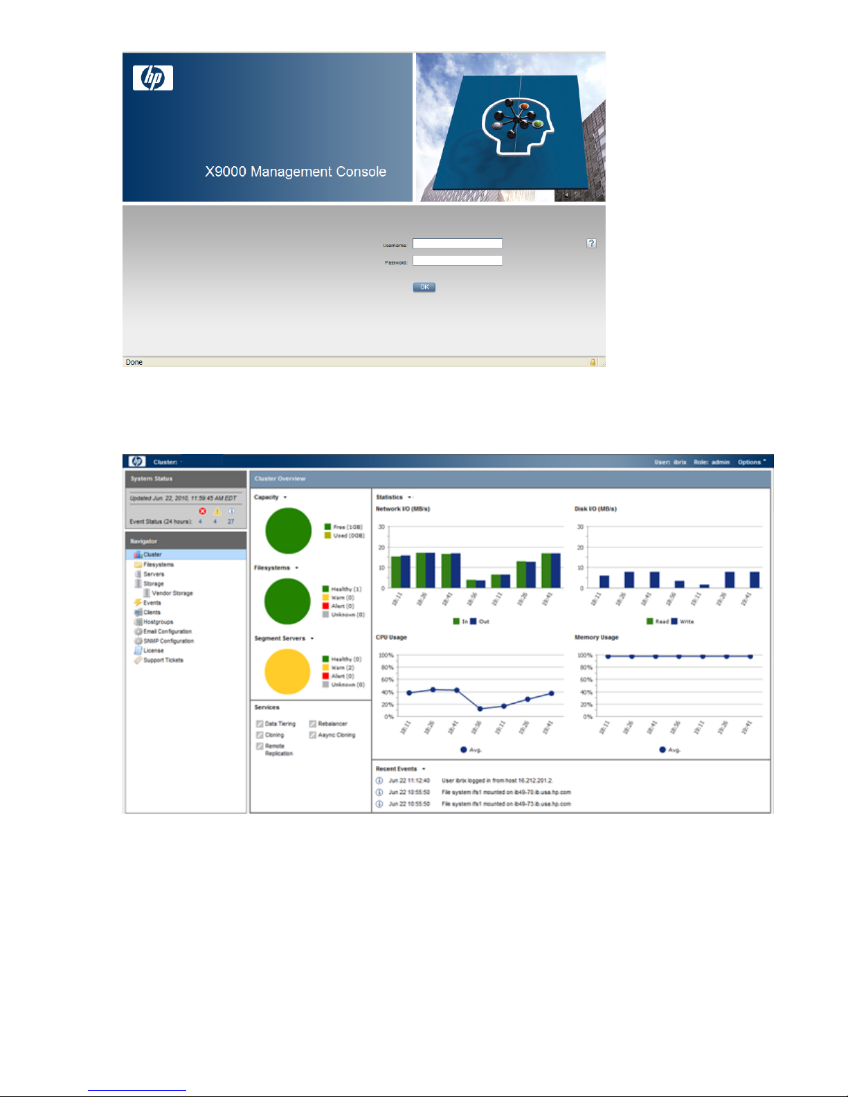
Using the GUI
The GUI is a browser-based interface to the management console. See the release notes for the
supported browsers and other software required to view charts on the dashboard.
If you are using HTTP to access the GUI, navigate to the following location, specifying port 80:
http://<management_console_IP>:80/fusion
If you are using HTTPS to access the GUI, navigate to the following location, specifying port 443:
https://<management_console_IP>:443/fusion
In these URLs, <management_console_IP> is the IP address of the management console user
VIF.
The GUI prompts for your user name and password. The default administrative user is ibrix.
Enter the password that was assigned to this user when the system was installed. (You can change
the password using the Linux passwd command.) To allow other users to access the GUI, see
“Adding user accounts for GUI access” (page 17).
Management interfaces 13
The GUI dashboard opens in the same browser window. You can open multiple GUI windows as
necessary. See the online help for information about all GUI displays and operations.
The GUI dashboard enables you to monitor the entire cluster. There are three parts to the dashboard:
System Status, Cluster Overview, and the Navigator.
14 Getting started
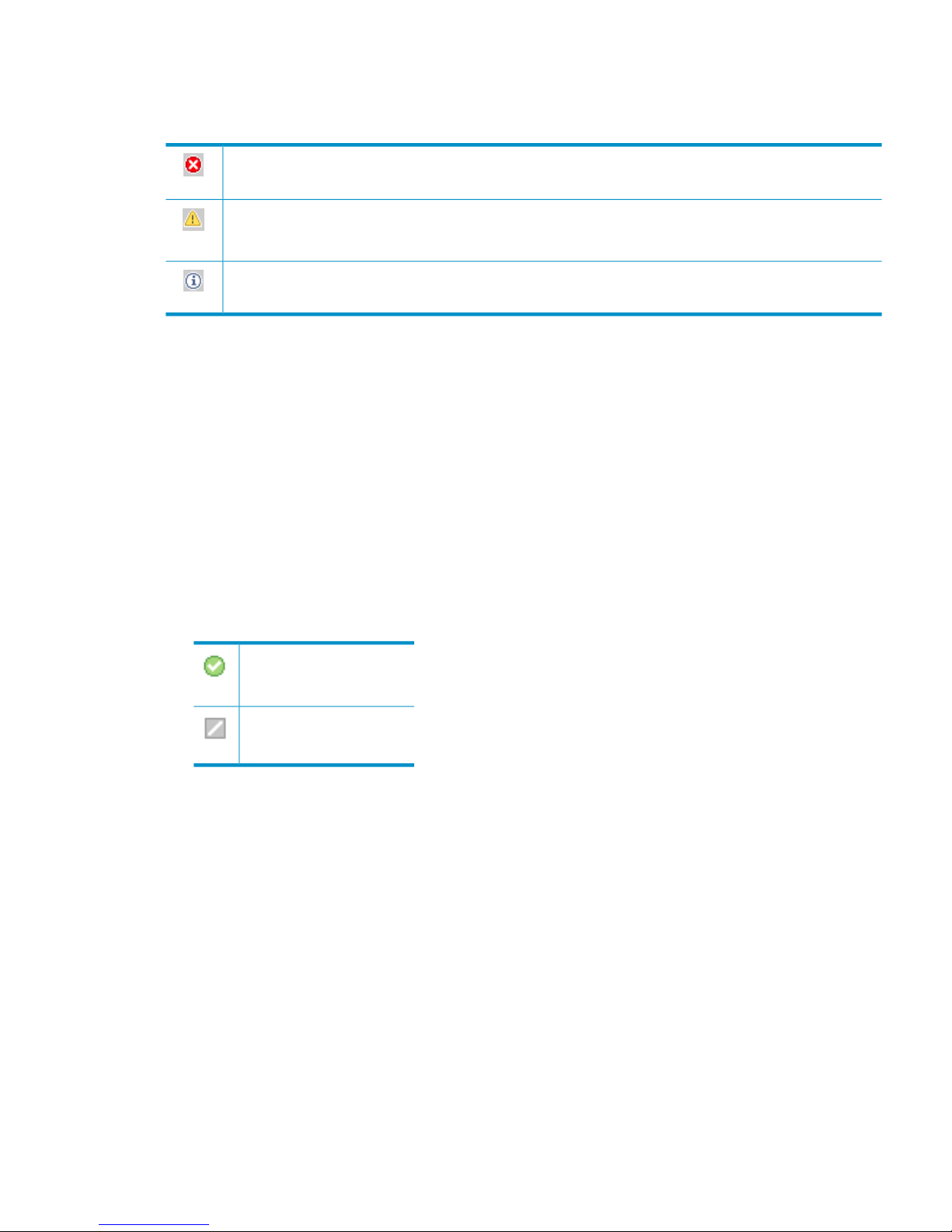
System Status
The System Status section lists the number of cluster events that have occurred in the last 24 hours.
There are three types of events:
Alerts. Disruptive events that can result in loss of access to file system data. Examples are a segment that is
unavailable or a server that cannot be accessed.
Warnings. Potentially disruptive conditions where file system access is not lost, but if the situation is not
addressed, it can escalate to an alert condition. Examples are a very high server CPU utilization level or a
quota limit close to the maximum.
Information. Normal events that change the cluster. Examples are mounting a file system or creating a
segment.
Cluster Overview
The Cluster Overview provides the following information:
Capacity
The amount of cluster storage space that is currently free or in use.
Filesystems
The current health status of the file systems in the cluster. The overview reports the number of
file systems in each state (healthy, experiencing a warning, experiencing an alert, or unknown).
Segment Servers
The current health status of the file serving nodes in the cluster. The overview reports the number
of nodes in each state (healthy, experiencing a warning, experiencing an alert, or unknown).
Services
Whether the specified file system services are currently running:
One or more tasks are
running.
No tasks are running.
Statistics
Historical performance graphs for the following items:
• Network I/O (MB/s)
• Disk I/O (MB/s)
• CPU usage (%)
• Memory usage (%)
On each graph, the X-axis represents time and the Y-axis represents performance.
Use the Statistics menu to select the servers to monitor (up to two), to change the maximum
value for the Y-axis, and to show or hide resource usage distribution for CPU and memory.
Recent Events
The most recent cluster events. Use the Recent Events menu to select the type of events to display.
You can also access certain menu items directly from the Cluster Overview. Mouse over the
Capacity, Filesystems or Segment Server indicators to see the available options.
Management interfaces 15
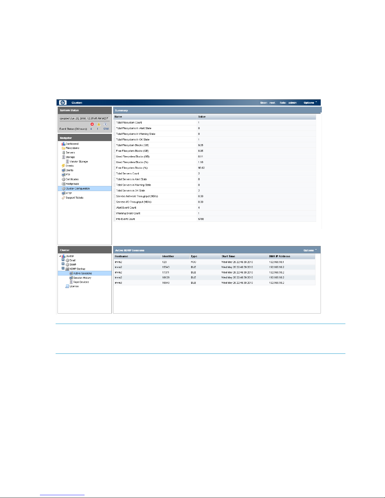
Navigator
The Navigator appears on the left side of the window and displays the cluster hierarchy. You can
use the Navigator to drill down in the cluster configuration to add, view, or change cluster objects
such as file systems or storage, and to initiate or view tasks such as snapshots or replication. When
you select an object, a details page shows a summary for that object. The lower Navigator allows
you to view details for the selected object, or to initiate a task. In the following example, we selected
Cluster Configuration in the Navigator, and the Summary shows configuration information. In the
lower Navigator, we selected NDMP Backup > Active Sessions to see details about the sessions.
NOTE: When you perform an operation on the GUI, a spinning finger is displayed until the
operation is complete. However, if you use Windows Remote Desktop to access the management
console, the spinning finger is not displayed.
Customizing the GUI
For most tables in the GUI, you can specify the columns that you want to display and the sort order
of each column. When this feature is available, mousing over a column causes the label to change
color and a pointer to appear. Click the pointer to see the available options. In the following
example, you can sort the contents of the Mountpoint column in ascending or descending order,
and you can select the columns that you want to appear in the display.
16 Getting started

Adding user accounts for GUI access
X9000 Software supports administrative and user roles. When users log in under the administrative
role, they can configure the cluster and initiate operations such as remote replication or snapshots.
When users log in under the user role, they can view the cluster configuration and status, but cannot
make configuration changes or initiate operations. The default administrative user name is ibrix.
The default regular username is ibrixuser.
Usernames for the administrative and user roles are defined in the /etc/group file. Administrative
users are specified in the ibrix-admin group, and regular users are specified in the ibrix-user
group. These groups are created when X9000 Software is installed. The following entries in the
/etc/group file show the default users in these groups:
ibrix-admin:x:501:root,ibrix
ibrix-user:x:502:ibrix,ibrixUser,ibrixuser
You can add other users to these groups as needed, using Linux procedures.
Using the CLI
The administrative commands described in this guide must be executed on the management console
host and require root privileges. The commands are located in $IBRIXHOME⁄bin. For complete
information about the commands, see the HP StorageWorks X9000 File Serving Software CLI
Reference Guide.
When using ssh to access the machine hosting the management console, specify the IP address
of the management console user VIF.
Starting the array management software
Depending on the array type, you can launch the array management software from the management
console GUI. In the Navigator, select Vendor Storage, select your array from the Vendor Storage
page, and click Launch Storage Management.
X9000 client interfaces
X9000 clients can access the management console as follows:
• Linux clients. Linux client commands can be used for tasks such as mounting or unmounting
file systems and displaying statistics. See the HP StorageWorks X9000 File Serving Software
CLI Reference Guide for details about these commands.
• Windows clients. The Windows client GUI can be used for tasks such as mounting or
unmounting file systems and registering Windows clients.
Using the Windows X9000 client GUI
The Windows X9000 client GUI is the client interface to the management console. To open the
GUI, double-click the desktop icon or select the IBRIX Client program from the Start menu on the
client. The client program contains tabs organized by function.
Management interfaces 17

NOTE: The Windows X9000 client application can be started only by users with Administrative
privileges.
• Status. Shows the client’s management console registration status and mounted file systems,
and provides access to the IAD log for troubleshooting.
• Registration. Registers the client with the management console, as described in the HP
StorageWorks File Serving Software Installation Guide.
• Mount. Mounts a file system. Select the Cluster Name from the list (the cluster name is the
management console name), enter the name of the file system to mount, select a drive, and
then click Mount. (If you are using Remote Desktop to access the client and the drive letter
does not appear, log out and log back in.)
• Umount. Unmounts a file system.
• Tune Host. Tunable parameters include the NIC to prefer (the client uses the cluster interface
by default unless a different network interface is preferred for it), the communications protocol
(UDP or TCP), and the number of server threads to use.
• Active Directory Settings. Displays current Active Directory settings.
Online help is also available for the client GUI.
X9000 Software manpages
X9000 Software provides manpages for most of its commands. To view the manpages, set the
MANPATH variable on the management console to include the path to the manpages and then
export it. The manpages are in the $IBRIXHOME/man directory. For example, if $IBRIXHOME is
/usr/local/ibrix (the default), you would set the MANPATH variable as follows on the
management console and then export the variable.
MANPATH=$MANPATH:/usr/local/ibrix/man
Changing passwords
You may want to change the passwords on your system:
• Hardware passwords. See the documentation for the specific hardware for more information.
• Root password. Use the passwd(8) command on each server in turn.
• X9000 Software user password. This password is created during installation and is used to
log on to the management console GUI. The default is ibrix. You can change the password
on the management console using the Linux passwd command. You will be prompted to enter
the new password.
# passwd ibrix
Configuring ports for a firewall
IMPORTANT: To avoid unintended consequences, HP recommends that you configure the firewall
during scheduled maintenance times.
When configuring a firewall, you should be aware of the following:
• SELinux should be disabled.
• By default, NFS uses random port numbers for operations such as mounting and locking.
These ports must be fixed so that they can be listed as exceptions in a firewall configuration
18 Getting started

file. For example, you will need to lock specific ports for rpc.statd, rpc.lockd,
rpc.mountd, and rpc.quotad.
• It is best to allow all ICMP types on all networks; however, you can limit ICMP to types 0, 3,
8, and 11 if necessary.
Be sure to open the ports listed in the following table.
DescriptionPort
SSH22/tcp
SSH for Onboard Administrator (OA); only for X9720 blades9022/tcp
NTP123/tcp, 123/upd
Multicast DNS, 224.0.0.2515353/udp
netperf tool12865/tcp
X9000 management console to file serving nodes80/tcp
443/tcp
X9000 management console and X9000 file system5432/tcp
8008/tcp
9002/tcp
9005/tcp
9008/tcp
9009/tcp
9200/tcp
Between file serving nodes and NFS clients (user network)
NFS
RPC
quota
lockmanager
lockmanager
mount daemon
stat
stat outgoing
reserved for use by a custom application (CMU) and can be disabled if not used
2049/tcp, 2049/udp
111/tcp, 111/udp
875/tcp, 875/udp
32803/tcp
32769/udp
892/tcp, 892/udp
662/tcp, 662/udp
2020/tcp, 2020/udp
4000:4003/tcp
Between file serving nodes and CIFS clients (user network)137/udp
138/udp
139/tcp
445/tcp
Between file serving nodes and X9000 clients (user network)9000:9002/tcp
9000:9200/udp
Between file serving nodes and FTP clients (user network)20/tcp, 20/udp
21/tcp, 21/udp
Between X9000 management console GUI and clients that need to access the GUI7777/tcp
8080/tcp
Dataprotector5555/tcp, 5555/udp
Internet Printing Protocol (IPP)631/tcp, 631/udp
Configuring ports for a firewall 19

HP Insight Remote Support software
HP Insight Remote Support supplements your monitoring, 24x7 to ensure maximum system availability
by providing intelligent event diagnosis, and automatic, secure submission of hardware event
notifications to HP, which will initiate a fast and accurate resolution, based on your product’s
service level. Notifications may be sent to your authorized HP Channel Partner for on-site service,
if configured and available in your country. The software is available in two variants:
• HP Insight Remote Support Standard: This software supports server and storage devices and
is optimized for environments with 1-50 servers. Ideal for customers who can benefit from
proactive notification, but do not need proactive service delivery and integration with a
management platform.
• HP Insight Remote Support Advanced: This software provides comprehensive remote monitoring
and proactive service support for nearly all HP servers, storage, network, and SAN
environments, plus selected non-HP servers that have a support obligation with HP. It is
integrated with HP Systems Insight Manager. A dedicated server is recommended to host both
HP Systems Insight Manager and HP Insight Remote Support Advanced.
Details for both versions are available at:
http://www.hp.com/go/insightremotesupport
The required components for HP Insight Remote Support are preinstalled on the file serving nodes.
You will need to install the Central Management Server (CMS) on a separate Windows system.
See the X9000 Series release notes for more information.
20 Getting started

3 Configuring virtual interfaces for client access
X9000 Software uses a cluster network interface to carry management console traffic and traffic
between file serving nodes. This network is configured as bond0 when the cluster is installed. For
clusters with an agile management console configuration, a virtual interface is also created for the
cluster network interface to provide failover support for the console.
Although the cluster network interface can carry traffic between file serving nodes and clients, HP
recommends that you configure one or more user network interfaces for this purpose. Typically,
bond1 is created for the first user network when the cluster is configured.
To provide high availability for a user network, you should configure a bonded virtual interface
(VIF) for the network and then set up failover for the VIF. This method prevents interruptions to client
traffic. If necessary, the file serving node hosting the VIF can fail over to its standby backup node,
and clients can continue to access the file system through the backup node.
Network and VIF guidelines
To provide high availability, the user interfaces used for client access should be configured as
bonded virtual interfaces (VIFs). Note the following:
• Nodes needing to communicate for file system coverage or for failover must be on the same
network interface. Also, nodes set up as a failover pair must be connected to the same network
interface.
• Use a Gigabit Ethernet port (or faster) for user networks.
• NFS, CIFS, FTP, and HTTP clients can use the same user VIF. The servers providing the VIF
should be configured in backup pairs, and the NICs on those servers should also be configured
for failover.
• For X9000 Linux and Windows clients, the servers hosting the VIF should be configured in
backup pairs. However, X9000 clients do not support backup NICs. Instead, X9000 clients
should connect to the parent bond of the user VIF or to a different VIF.
Creating a bonded VIF
Use the following procedure to create a bonded VIF (bond1:1 in this example):
1. If high availability (automated failover) is configured on the servers, disable it. Run the following
command on the management console:
# ibrix_server –m -U
2. Identify the bond1:1 VIF:
# ibrix_nic –a -n bond1:1 –h node1,node2,node3,node4
3. Assign an IP address to the bond1:1 VIFs on each node. In the command, -I specifies the
IP address, -M specifies the netmask, and -B specifies the broadcast address:
# ibrix_nic –c –n bond1:1 –h node1 –I 16.123.200.201 –M 255.255.255.0 -B 16.123.200.255
# ibrix_nic –c –n bond1:1 –h node2 –I 16.123.200.202 –M 255.255.255.0 -B 16.123.200.255
# ibrix_nic –c –n bond1:1 –h node3 –I 16.123.200.203 –M 255.255.255.0 -B 16.123.200.255
# ibrix_nic –c –n bond1:1 –h node4 –I 16.123.200.204 –M 255.255.255.0 -B 16.123.200.255
Configuring standby backup nodes
Assign standby backup nodes for the bond1:1 interface. The backup nodes should be configured
in pairs. For example, node1 is the backup for node2, and node2 is the backup for node1.
Network and VIF guidelines 21

1. Identify the VIF:
# ibrix_nic –a -n bond1:2 –h node1,node2,node3,node4
2. Set up a standby server for each VIF:
# ibric_nic –b –H node1/bond1:1,node2/bond1:2
# ibric_nic –b –H node2/bond1:1,node1/bond1:2
# ibric_nic –b –H node3/bond1:1,node4/bond1:2
# ibric_nic –b –H node4/bond1:1,node3/bond1:2
Configuring NIC failover
NIC monitoring should be configured on VIFs that will be used by NFS, CIFS, FTP, or HTTP. Use
the same backup pairs that you used when configuring standby servers. For example:
# ibric_nic –m -h node1 -A node2/bond1:1
# ibric_nic –m -h node2 -A node1/bond1:1
# ibric_nic –m -h node3 -A node4/bond1:1
# ibric_nic –m -h node4 -A node3/bond1:1
Configuring automated failover
To enable automated failover for your file serving nodes, execute the following command:
ibrix_server —m [-h SERVERNAME]
Example configuration
This example uses two nodes, ib50-81 and ib50-82. These nodes are backups for each other,
forming a backup pair.
[root@ib50-80 ~]# ibrix_server -l
Segment Servers
===============
SERVER_NAME BACKUP STATE HA ID GROUP
----------- ------- ------------ --- ------------------------------------ ----ib50-81 ib50-82 Up on 132cf61a-d25b-40f8-890e-e97363ae0d0b servers
ib50-82 ib50-81 Up on 7d258451-4455-484d-bf80-75c94d17121d servers
All VIFs on ib50-81 have backup (standby) VIFs on ib50-82. Similarly, all VIFs on ib50-82
have backup (standby) VIFs on ib50-81. NFS, CIFS, FTP, and HTTP clients can connect to bond1:1
on either host. If necessary, the selected server will fail over to bond1:2 on the opposite host.
X9000 clients could connect to bond1 on either host, as these clients do not support or require
NIC failover. (The following sample output shows only the relevant fields.)
[root@ib50-80 ~]# ibrix_nic -l
HOST IFNAME TYPE STATE IP_ADDRESS BACKUP_HOST BACKUP_IF
------- ------ ------- ------------------- ------------- ----------- --------ib50-81 bond1:1 User Up, LinkUp 16.226.50.220 ib50-82 bond1:1
ib50-81 bond0 Cluster Up, LinkUp 172.16.0.81
ib50-81 bond1:2 User Inactive, Standby
ib50-81 bond1 User Up, LinkUp 16.226.50.81
ib50-82 bond0 Cluster Up, LinkUp 172.16.0.82
ib50-82 bond1 User Up, LinkUp 16.226.50.82
ib50-82 bond1:2 User Inactive, Standby
ib50-82 bond1:1 User Up, LinkUp 16.226.50.228 ib50-81 bond1:1
Specifying VIFs in the client configuration
When you configure your clients, you may need to specify the VIF that should be used for client
access.
NFS/CIFS. Specify the VIF IP address of the servers (for example, bond1:0) to establish connection.
You can also configure DNS round robin to ensure NFS or CIFS client-to-server distribution. In both
cases, the NFS/CIFS clients will cache the initial IP they used to connect to the respective share,
usually until the next reboot.
22 Configuring virtual interfaces for client access

FTP. When you add an FTP share on the Add FTP Shares dialog box or with the ibrix_ftpshare
command, specify the VIF as the IP address that clients should use to access the share.
HTTP. When you create a virtual host on the Create Vhost dialog box or with the
ibrix_httpvhost command, specify the VIF as the IP address that clients should use to access
shares associated with the Vhost.
X9000 clients. Use the following command to prefer the appropriate user network. Execute the
command once for each destination host that the client should contact using the specified interface.
ibrix_client -n -h SRCHOST -A DESTNOST/IFNAME
For example:
ibrix_client -n -h client12.mycompany.com -A ib50-81.mycompany.com/bond1
NOTE: Because the backup NIC cannot be used as a preferred network interface for X9000
clients, add one or more user network interfaces to ensure that HA and client communication work
together.
Support for link state monitoring
Do not configure link state monitoring for user network interfaces or VIFs that will be used for CIFS
or NFS. Link state monitoring is supported only for use with iSCSI storage network interfaces, such
as those provided with X9300 Gateway systems.
Support for link state monitoring 23

4 Configuring failover
This chapter describes how to configure failover for agile management consoles, file serving nodes,
network interfaces, and HBAs.
Agile management consoles
The management console maintains the cluster configuration and provides graphical and
command-line user interfaces for managing and monitoring the cluster. Typically, one active
management console and one passive management console are installed when the cluster is
installed. This is called an agile management console configuration.
NOTE: Optionally, the management console can be installed on a dedicated Management
Server. This section describes the agile management console configuration.
Agile management console modes
An agile management console can be in one of the following modes:
• active. In this mode, the management console controls console operations. All cluster
administration and configuration commands must be run from the active management console.
• passive. In this mode, the management console monitors the health of the active management
console. If the active management console fails, the passive management console becomes
the active console.
• maintenance. In this mode, the management console does not participate in console operations.
Maintenance mode should be used for operations such as manual failover of the active
management console, X9000 Software upgrades, and blade replacements.
Agile management consoles and failover
Using an agile management console configuration provides high availability for management
console services. If the active management console fails, the cluster virtual interface will go down.
When the passive management console detects that the cluster virtual interface is down, it will
become the active console. This management console rebuilds the cluster virtual interface, starts
management console services locally, transitions into active mode, and take over management
console operation.
Failover of the active management console affects the following features:
• User networks. The virtual interface used by clients will also fail over. Users may notice a brief
reconnect while the newly active management console takes over management of the virtual
interface.
• Support tickets. The existing support ticket information is not moved to the newly active
management console. Support Ticket operations are always handled by the active management
console and the final output of the operations is stored there.
• Management console GUI. You will need to reconnect to the management console VIF after
the failover.
Failing over the management console manually
To fail over the active management console manually, place the console into maintenance mode.
Enter the following command on the node hosting the console:
ibrix_fm -m maintenance
The command takes effect immediately.
24 Configuring failover

The failed-over management console remains in maintenance mode until it is moved to passive
mode using the following command:
ibrix_fm -m passive
A management console cannot be moved from maintenance mode to active mode.
Viewing information about management consoles
To view mode information, use the following command:
ibrix_fm –i
NOTE: If the management console was not installed in an agile configuration, the output will
report FusionServer: fusion manager name not set! (active, quorum is not
configured).
When a management console is installed, it is registered in the management console configuration.
To view a list of all registered management consoles, use the following command:
ibrix_fm –f
Cluster high availability
X9000 Software High Availability keeps your data accessible at all times. Failover protection can
be configured for file serving nodes, network interfaces, individual segments, and HBAs. Through
physical and logical configuration policies, you can set up a flexible and scalable high availability
solution. X9000 clients experience no changes in service and are unaware of the failover events.
Failover modes
High Availability has two failover modes: the default manual failover and the optional automated
failover. A manual failover uses the ibrix_server command or the management console GUI
to fail over a file serving node to its standby. The server can be powered down or remain up during
the procedure. Manual failover also includes failover of any network interfaces having defined
standbys. You can perform a manual failover at any time, regardless of whether automated failover
is in effect.
Automated failover allows the management console to initiate failover when it detects that
standby-protected components have failed. A basic automated failover setup protects all file serving
nodes. A comprehensive setup also includes network interface monitoring to protect user network
interfaces and HBA monitoring to protect access from file serving nodes to storage via an HBA.
When automated failover is enabled, the management console listens for heartbeat messages that
the file serving nodes broadcast at one-minute intervals. The management console automatically
initiates failover when it fails to receive five consecutive heartbeats or, if HBA monitoring is enabled,
when a heartbeat message indicates that a monitored HBA or pair of HBAs has failed.
If network interface monitoring is enabled, automated failover occurs when the management console
receives a heartbeat message indicating that a monitored network might be down and then the
console cannot reach that interface.
If a file serving node fails over, you will need to manually fail back the node.
What happens during a failover
The following events occur during automated or manual failover of a file serving node to its standby:
1. The management console verifies that the standby is powered on and accessible.
2. The management console migrates ownership of the node’s segments to the standby and
notifies all file serving nodes and X9000 clients about the migration. This is a persistent change.
3. If network interface monitoring has been set up, the management console activates the standby
user network interface and transfers the IP address of the node’s user network interface to it.
Cluster high availability 25

To determine the progress of a failover, view the Status tab on the GUI or execute the
ibrix_server -l command. While the management console is migrating segment ownership,
the operational status of the node is Up-InFailover or Down-InFailover, depending on whether the
node was powered up or down when failover was initiated. When failover is complete, the
operational status changes to Up-FailedOver or Down-FailedOver. For more information about
operational states, see “Monitoring the status of file serving nodes” (page 47).
Both automated and manual failovers trigger an event that is reported on the GUI.
Setting up automated failover
The recommended minimum setup for automated failover protection is as follows:
1. Identify standbys for file serving nodes or specific segments. You must implement either
server-level or segment-level standby protection; you cannot implement both.
2. Identify power sources for file serving nodes. For APC power sources, associate file serving
nodes to power source slots.
3. Turn on automated failover.
If your cluster includes one or more user network interfaces carrying NFS/CIFS client traffic, HP
recommends that you identify standby network interfaces and set up network interface monitoring.
If your file serving nodes are connected to storage via HBAs, HP recommends that you set up HBA
monitoring.
Identifying standbys for file serving nodes
file serving nodes can be configured to provide standby service for one another in the following
configurations:
• 1 x 1. Set up standby pairs, where each server in a pair is the standby for the other.
• 1 x N. Assign the same standby to a certain number of primaries.
Contact HP Support for recommendations based on your environment.
The following restrictions apply to all types of standby configurations:
• The management console must have access to both the primary server and its standby.
• The same file system must be mounted on both the primary server and its standby.
• A server identified as a standby must be able to see all segments that might fail over to it.
• In a SAN environment, a primary server and its standby must use the same storage infrastructure
to access a segment’s physical volumes (for example, a multiported RAID array).
To identify a standby for a file serving node, use the following command:
<installdirectory>/bin/ibrix_server -b -h HOSTNAME1,HOSTNAME2
For example, to identify node s2.hp.com as the standby for all segments on node s1.hp.com:
<installdirectory>/bin/ibrix_server -b -h s1.hp.com,s2.hp.com
For performance reasons, you might want to fail over specific segments to a standby instead of
failing over all segments on a node to a standby. Use this command to identify the segments:
<installdirectory>/bin/ibrix_fs -b -f FSNAME -s LVLIST -h HOSTNAME
For example, to identify node s1.hp.com as the standby for segments ilv_1, ilv_2, and ilv_3 in file
system ifs1:
<installdirectory>/bin/ibrix_fs -b -f ifs1 -s ilv_1,ilv_2,ilv_3 -h s1.hp.com
Identifying power sources
To implement automated failover, perform a forced manual failover, or remotely power a file
serving node up or down, you must set up programmable power sources for the nodes and their
standbys. Using programmable power sources prevents a “split-brain scenario” between a failing
26 Configuring failover

file serving node and its standby, allowing the failing server to be centrally powered down by the
management console in the case of automated failover, and manually in the case of a forced
manual failover.
X9000 Software works with iLO, IPMI, OpenIPMI, and OpenIPMI2 integrated power sources and
with APC power sources.
Preliminary configuration
Certain configuration steps are required when setting up power sources:
• All types. If you plan to implement automated failover, ensure that the management console
has LAN access to the power sources.
• Integrated power sources. Install the environment and any drivers and utilities, as specified
by the vendor documentation. If you plan to protect access to the power sources, set up the
UID and password to be used.
• APC. Enable SNMP access. Set the Community Name to ibrix and the Access Type to
write+. If write+ does not work with your configuration, set the Access Type to write.
Identifying power sources
All power sources must be identified to the configuration database before they can be used.
Integrated power sources. To identify an integrated power source, use the following command:
<installdirectory>/bin/ibrix_powersrc -a -t {ipmi|openipmi|openipmi2|ilo}
-h HOSTNAME -I IPADDR -u USERNAME -p PASSWORD
For example, to identify an iLO power source at IP address 192.168.3.170 for node ss01:
<installdirectory>/bin/ibrix_powersrc -a -t ilo -h ss01 -I 192.168.3.170
-u Administrator -p password
APC power source. To identify an APC power source, use the following command:
<installdirectory>/bin/ibrix_powersrc -a -t {apc|apc_msp} -h POWERSRCNAME -n NUMSLOTS
-I IPADDR
For example, to identify an eight-port APC power source named ps1 at IP address 192.168.3.150:
<installdirectory>/bin/ibrix_powersrc -a -t apc -h ps1 -n 8 -I 192.168.3.150
For APC power sources, you must also associate file serving nodes to power source slots. (This
step is unnecessary for integrated power sources because the nodes are connected by default to
slot 1.) Use the following command:
<installdirectory>/bin/ibrix_hostpower -a -i SLOTID -s POWERSOURCE -h HOSTNAME
For example, to identify that node s1.hp.com is connected to slot 1 on APC power source ps1:
<installdirectory>/bin/ibrix_hostpower -a -i 1 -s ps1 -h s1.hp.com
Updating the configuration database with power source changes
If you move a file serving node to a different power source slot, unplug it from a power source
slot, or change its IP address or password, you must update the configuration database with the
changes. To do this, use the following command. The user name and password options are needed
only for remotely managed power sources. Include the -s option to have the management console
skip BMC.
<installdirectory>/bin/ibrix_powersrc -m [-I IPADDR] [-u USERNAME] [-p PASSWORD]
[-s] -h POWERSRCLIST
The following command changes the IP address for power source ps1:
<installdirectory>/bin/ibrix_powersrc -m -I 192.168.3.153 -h ps1
To change the APC slot association for a file serving node, use the following command:
<installdirectory>/bin/ibrix_hostpower -m -i FROM_SLOT_ID,TO_SLOT_ID -s POWERSOURCE
-h HOSTNAME
Cluster high availability 27

For example, to identify that node s1.hp.com has been moved from slot 3 to slot 4 on APC power
source ps1:
<installdirectory>/bin/ibrix_hostpower -m -i 3,4 -s ps1 -h s1.hp.com
Dissociating a file serving node from a power source
You can dissociate a file serving node from an integrated power source by dissociating it from
slot 1 (its default association) on the power source. Use the following command:
<installdirectory>/bin/ibrix_hostpower -d -s POWERSOURCE -h HOSTNAME
To dissociate a file serving node from an APC power source on the specified slot, use the following
command. To dissociate the node from all slots on the power source, omit the -i option.
<installdirectory>/bin/ibrix_hostpower -d [-s POWERSOURCE [-i SLOT]] -h HOSTNAME
For example, to dissociate file serving node s1.hp.com from slot 3 on APC power source ps1:
<installdirectory>/bin/ibrix_hostpower -d -s ps1 -i 3 -h s1.hp.com
Deleting power sources from the configuration database
To conserve storage, delete power sources that are no longer in use from the configuration database.
If you are deleting multiple power sources, use commas to separate them.
<installdirectory>/bin/ibrix_powersrc -d -h POWERSRCLIST
Turning automated failover on and off
Automated failover is turned off by default. When automated failover is turned on, the management
console starts monitoring heartbeat messages from file serving nodes. You can turn automated
failover on and off for all file serving nodes or for selected nodes.
To turn on automated failover, use the following command:
<installdirectory>/bin/ibrix_server -m [-h SERVERNAME]
To turn off automated failover, include the -U option:
<installdirectory>/bin/ibrix_server -m -U [-h SERVERNAME]
To turn automated failover on or off for a single file serving node, include the -h SERVERNAME
option.
Manually failing over a file serving node
To set up a cluster for manual failover, first identify server-level or segment-level standbys for each
file serving node, as described in “Identifying standbys for file serving nodes” (page 26).
Manual failover does not require the use of programmable power supplies. However, if you have
installed and identified power supplies for file serving nodes, you can power down a server before
manually failing it over. You can fail over a file serving node manually, even when automated
failover is turned on.
A file serving node can be failed over from the GUI or the CLI.
On the CLI, complete the following steps:
1. Run ibrix_server -f, specifying the node to be failed over in the HOSTNAME option. If
appropriate, include the -p option to power down the node before segments are migrated:
<installdirectory>/bin/ibrix_server -f [-p] -h HOSTNAME
2. Determine whether the failover was successful:
<installdirectory>/bin/ibrix_server -l
The contents of the STATE field indicate the status of the failover. If the field persistently shows
Down-InFailover or Up-InFailover, the failover did not complete; contact HP Support for assistance.
For information about the values that can appear in the STATE field, see “What happens during
a failover” (page 25).
28 Configuring failover

Failing back a file serving node
After automated or manual failover of a file serving node, you must manually fail back the server,
which restores ownership of the failed-over segments and network interfaces to the server. Before
failing back the node, confirm that the primary server can see all of its storage resources and
networks. The segments owned by the primary server will not be accessible if the server cannot
see its storage.
To fail back a file serving node, use the following command. The HOSTNAME argument specifies
the name of the failed-over node.
<installdirectory>/bin/ibrix_server -f -U -h HOSTNAME
After failing back the node, determine whether the failback completed fully. If the failback is not
complete, contact HP Support for assistance.
NOTE: A failback might not succeed if the time period between the failover and the failback is
too short, and the primary server has not fully recovered. HP recommends ensuring that both servers
are up and running and then waiting 60 seconds before starting the failback. Use the
ibrix_server -l command to verify that the primary server is up and running. The status should
be Up-FailedOver before performing the failback.
Using network interface monitoring
With network interface monitoring, one file serving node monitors another file serving node over
a designated network interface. If the monitoring server loses contact with its destination server
over the interface, it notifies the management console. If the management console also cannot
contact the destination server over that interface, it fails over both the destination server and the
network interface to their standbys. Clients that were mounted on the failed-over server do not
experience any service interruption and are unaware that they are now mounting the file system
on a different server.
Unlike X9000 clients, NFS and CIFS clients cannot reroute file requests to a standby if the file
serving node where they are mounted should fail. To ensure continuous client access to files, HP
recommends that you put NFS/CIFS traffic on a user network interface (see “Preferring network
interfaces” (page 60)), and then implement network interface monitoring for it.
Comprehensive protection of NFS/CIFS traffic also involves setting up network interface monitoring
for the cluster interface. Although the management console will eventually detect interruption of a
file serving node’s connection to the cluster interface and initiate segment failover if automated
failover is turned on, failover will occur much faster if the interruption is detected via network
interface monitoring. (If automated failover is not turned on, you will begin to see file access
problems if the cluster interface fails.) There is no difference in the way that monitoring is set up
for the cluster interface and a user network interface. In both cases, you set up file serving nodes
to monitor each other over the interface.
Sample scenario
The following diagram illustrates a monitoring and failover scenario in which a 1:1 standby
relationship is configured. Each standby pair is also a network interface monitoring pair. When
SS1 loses its connection to the user network interface (eth1), as shown by the red X, SS2 can no
longer contact SS1 (A). SS2 notifies the management console, which then tests its own connection
with SS1 over eth1 (B). The management console cannot contact SS1 on eth1, and initiates
failover of SS1’s segments (C) and user network interface (D).
Cluster high availability 29
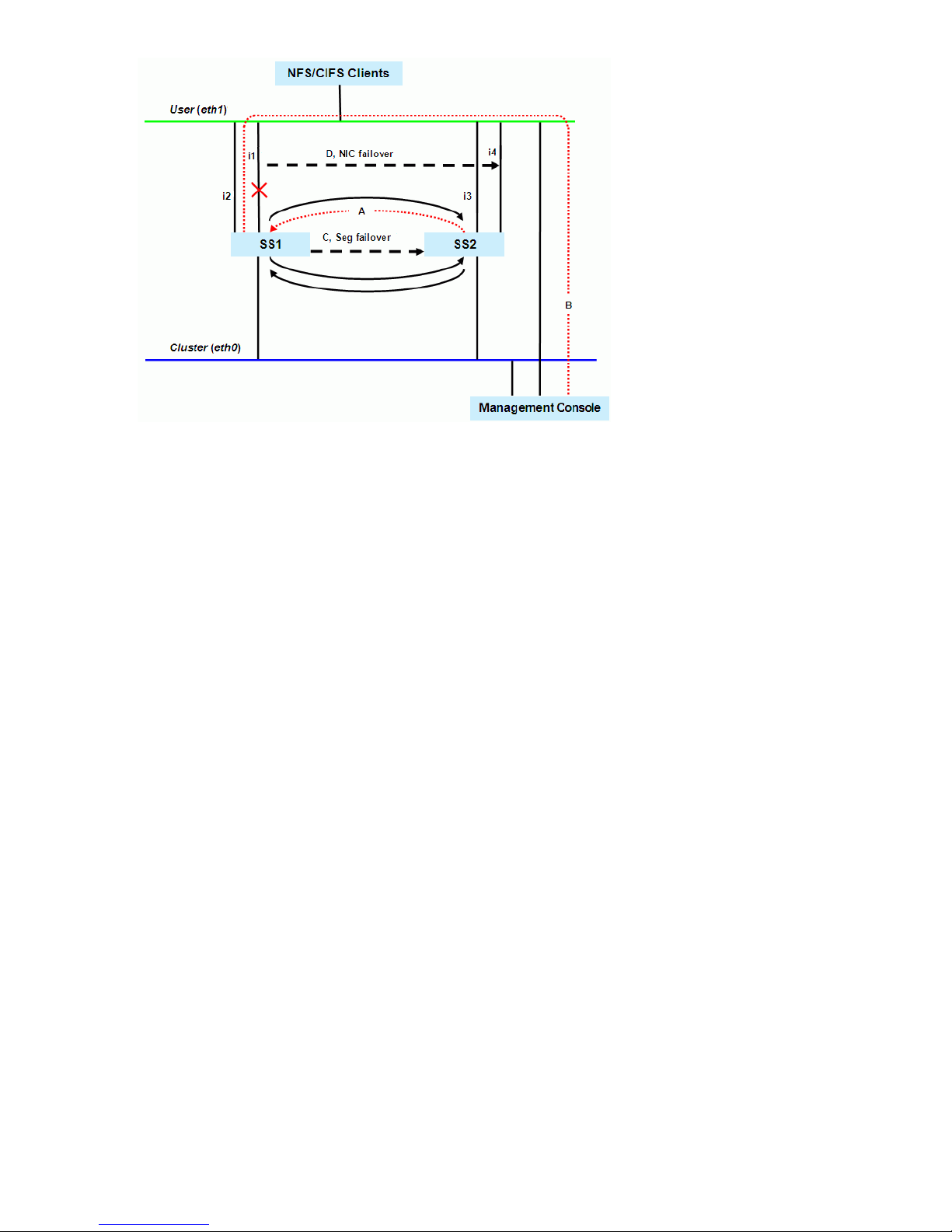
Identifying standbys
To protect a network interface, you must identify a standby for it on each file serving node that
connects to the interface. The following restrictions apply when identifying a standby network
interface:
• The standby network interface must be unconfigured and connected to the same switch (network)
as the primary interface.
• The file serving node that supports the standby network interface must have access to the file
system that the clients on that interface will mount.
Virtual interfaces are highly recommended for handling user network interface failovers. If a VIF
user network interface is teamed/bonded, failover occurs only if all teamed network interfaces
fail. Otherwise, traffic switches to the surviving teamed network interfaces.
To identify standbys for a network interface, execute the following command once for each file
serving node. IFNAME1 is the network interface that you want to protect and IFNAME2 is the
standby interface.
<installdirectory>/bin/ibrix_nic -b -H HOSTNAME1/IFNAME1,HOSTNAME2/IFNAME2
The following command identifies virtual interface eth2:2 on file serving node s2.hp.com as the
standby interface for interface eth2 on file serving node s1.hp.com:
<installdirectory>/bin/ibrix_nic -b -H s1.hp.com/eth2,s2.hp.com/eth2:2
Setting up a monitor
File serving node failover pairs can be identified as network interface monitors for each other.
Because the monitoring must be declared in both directions, this is a two-pass process for each
failover pair.
To set up a network interface monitor, use the following command:
<installdirectory>/bin/ibrix_nic -m -h MONHOST -A DESTHOST/IFNAME
For example, to set up file serving node s2.hp.com to monitor file serving node s1.hp.com over
user network interface eth1:
<installdirectory>/bin/ibrix_nic -m -h s2.hp.com -A s1.hp.com/eth1
To delete network interface monitoring, use the following command:
<installdirectory>/bin/ibrix_nic -m -h MONHOST -D DESTHOST/IFNAME
30 Configuring failover
 Loading...