

Page 1

HP Smart Array 6i Controller
User Guide
December 2003 (First Edition)
Part Number 347914-001
Page 2

© Copyright 2003 Hewlett-Packard Development Company, L.P.
The information contained herein is subject to change without notice. The only warranties for HP products
and services are set forth in the express warranty statements accompanying such products and services.
Nothing herein should be construed as constituting an additional warranty. HP shall not be liable for
technical or editorial errors or omissions contained herein.
Microsoft and Windows are U.S. registered trademarks of Microsoft Corporation.
HP Smart Array 6i Controller User Guide
December 2003 (First Edition)
Part Number 347914-001
Audience Assumptions
This guide is for the person who installs, administers, and troubleshoots servers and storage
systems. HP assumes you are qualified in the servicing of computer equipment and trained in
recognizing hazards in products with hazardous energy levels.
Page 3

3
Contents
Overview of the Server Setup Procedure 5
Setting Up An Autoconfigurable Server.............................................................................................. 5
Updating the Firmware 7
Methods for Updating the Firmware.................................................................................................... 7
Configuring an Array 9
Introduction.......................................................................................................................................... 9
Comparing the Utilities......................................................................................................................10
Using ACU.........................................................................................................................................11
Using ORCA......................................................................................................................................11
Configuration Procedure.........................................................................................................12
Installing the Device Drivers 15
Installing the Device Drivers .............................................................................................................15
Installing the Management Agents 17
Installing Management Agents ..........................................................................................................17
Using the Battery-Backed Write Cache Option 19
Recovering Data from the Battery-Backed Write Cache ...................................................................19
Replacing the Battery Pack................................................................................................................ 20
Replacing, Moving, or Adding Hard Drives 23
Identifying the Status of a Hard Drive............................................................................................... 23
Hot-Plug SCSI Hard Drive LED Combinations..................................................................... 24
Recognizing Hard Drive Failure........................................................................................................25
Effects of a Hard Drive Failure...............................................................................................25
Compromised Fault Tolerance................................................................................................26
Recovering from Compromised Fault Tolerance....................................................................26
Replacing Hard Drives....................................................................................................................... 27
Factors to Consider Before Replacing Hard Drives................................................................27
Automatic Data Recovery (Rebuild) ......................................................................................29
Upgrading Hard Drive Capacity.............................................................................................30
Moving Drives and Arrays.................................................................................................................31
Adding Drives....................................................................................................................................33
Page 4

4 HP Smart Array 6i Controller User Guide
Diagnosing Array Problems 35
Diagnostic Tools ................................................................................................................................35
Probability of Logical Drive Failure 37
Factors Involved in Logical Drive Failure......................................................................................... 37
Probability of Logical Drive Failure vs. Number of Drives in Array..................................... 38
Drive Arrays and Fault-Tolerance Methods 39
Drive Arrays.......................................................................................................................................39
Fault-Tolerance Methods...................................................................................................................42
Hardware-Based Fault-Tolerance Methods............................................................................ 42
Alternative Fault-Tolerance Methods.....................................................................................48
Electrostatic Discharge 51
Preventing Electrostatic Discharge ....................................................................................................51
Grounding Methods to Prevent Electrostatic Discharge.................................................................... 52
Acronyms and Abbreviations 53
Index 55
Page 5

5
Overview of the Server Setup Procedure
In This Section
Setting Up An Autoconfigurable Server.........................................................................................5
Setting Up An Autoconfigurable Server
New HP ProLiant server models self-configure when they are powered up for the
first time. During this autoconfiguration process, the system language is set to
English by default, and Microsoft® Windows® 2000 is selected as the default
operating system. (However, the operating system must still be installed. This is
done later in the overall server setup procedure.) Also, if the server has fewer
than seven physical drives installed, they are automatically configured into a
logical drive with a suitable RAID level.
For more information about the autoconfiguration process, refer to the serverspecific setup and installation guide or the HP ROM-Based Setup Utility User
Guide.
IMPORTANT: Do not power up the server until the hardware
configuration is satisfactory, as described in the procedure given in this
section.
To set up the server:
1. Install physical drives if necessary. (The number of drives present determines
the RAID level that is autoconfigured. For details, refer to the server-specific
setup and installation guide or the HP ROM-Based Setup Utility User Guide.)
2. Power up the server. The autoconfiguration process runs. (To change the
system language or operating system from their default settings, press the F9
key. This action opens RBSU, which allows you to manually configure the
server.)
3. When autoconfiguration has finished running, use the SmartStart CD that is
supplied in the server kit to install the operating system and device drivers.
Instructions are provided with the CD.
Page 6

6 HP Smart Array 6i Controller User Guide
4. Create and format additional logical drives if desired ("Configuring an
Array" on page 9
).
The server is now ready to use.
Page 7

7
Updating the Firmware
In This Section
Methods for Updating the Firmware ..............................................................................................7
Methods for Updating the Firmware
To update the firmware on the server, controller, or hard drives, use Smart
Components. These components are available on the Firmware Maintenance CD.
A more recent version of a particular component might be available on the
support page of the HP website (http://www.hp.com/support
controller and hard drive firmware updates are also available from the software
and drivers page for storage products
(http://www.hp.com/support/proliantstorage).
1. Find the most recent version of the component that you require. Components
for controller firmware updates are available in offline and online formats.
2. Follow the instructions for installing the component on the server. These
instructions are given with the CD and are provided on the same Web page
as the component.
3. Follow the additional instructions that describe how to use the component to
flash the ROM. These instructions are provided with each component.
). Components for
Page 8

Page 9

9
Configuring an Array
In This Section
Introduction ....................................................................................................................................9
Comparing the Utilities ................................................................................................................10
Using ACU ...................................................................................................................................11
Using ORCA ................................................................................................................................11
Introduction
HP provides two utilities for manually configuring an array on a Smart Array
controller:
• ACU—A versatile, browser-based utility that provides maximum control
over configuration parameters
• ORCA—A simple ROM-based configuration utility that runs on all
operating systems
NOTE: To copy a particular array configuration to several other servers
on the same network, use ACR or the scripting capability of ACU. ACR
is provided in the SmartStart Scripting Toolkit, available on the HP
website (http://www.hp.com/servers/sstoolkit
).
Whichever utility you use, the following limitations apply:
• For the most efficient use of drive space, do not mix drives of different
capacities within the same array. The configuration utility treats all physical
drives in an array as if they have the same capacity as the smallest drive in
the array. The excess capacity of any larger drives is wasted because it is
unavailable for data storage.
• The probability that an array will experience a drive failure increases with
the number of physical drives in the array. If you configure a logical drive
with RAID 5, keep the probability of failure low by using no more than 14
physical drives in the array.
Page 10

10 HP Smart Array 6i Controller User Guide
For information about default array configuration settings, refer to the HP Array
Configuration Utility User Guide. This document is available on the
Documentation CD that is provided in the controller kit.
For conceptual information about arrays, logical drives, and fault-tolerance
methods, refer to "Drive Arrays and Fault-Tolerance Methods (on page 39
Comparing the Utilities
NOTE: In both tables, a y in the appropriate column indicates that the
feature or procedure is supported, while an n indicates that the feature
Supported Features ACU ORCA
Uses a graphical interface y n
Available in languages other than English y n
Executable at any time y n
Available on CD y n
or procedure is not supported.
)."
Uses a wizard to suggest the optimum configuration for an unconfigured
y n
controller
Describes configuration errors y n
Supported Procedures ACU ORCA
Creation and deletion of arrays and logical drives y y
Assignment of RAID level y y
Sharing of spare drives among several arrays y n
Assignment of multiple spare drives per array y n
Setting of stripe size y n
Migration of RAID level or stripe size y n
Configuration of controller settings y n
Expansion of an array y n
Creation of multiple logical drives per array y n
Setting of boot controller n y
Page 11

Configuring an Array 11
Using ACU
For detailed information about using ACU, refer to the HP Array Configuration
Utility User Guide. This document is available on the Documentation CD that is
provided in the controller kit.
Using ORCA
When a server is powered up, POST runs, and any array controllers that are in
the system are initialized. If the array controller supports ORCA, POST
temporarily halts, and an ORCA prompt message is displayed for approximately
five seconds. (If ORCA is not supported, the prompt message is not displayed,
and the system continues with the startup sequence.)
Page 12
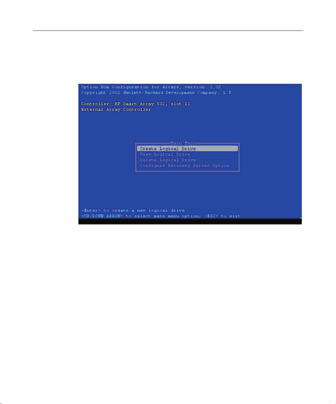
12 HP Smart Array 6i Controller User Guide
While the prompt is displayed, press the F8 key to start ORCA. The ORCA main
menu is displayed, allowing you to create, view, or delete a logical drive. (On a
ProLiant system, you can also use ORCA to set the currently selected controller
as the boot controller.)
Configuration Procedure
To create a logical drive using ORCA:
1. Select Create Logical Drive.
The screen displays a list of all available (unconfigured) physical drives and
the valid RAID options for the system.
2. Use the Arrow keys, Spacebar, and Tab key to navigate around the screen
and set up the logical drive, including an online spare drive if one is required.
NOTE: You cannot use ORCA to configure one spare drive to be
shared among several arrays. Only ACU enables you to configure
shared spare drives.
3. Press the Enter key to accept the settings.
Page 13

Configuring an Array 13
4. Press the F8 key to confirm the settings and save the new configuration.
After several seconds, the Configuration Saved screen appears.
5. Press the Enter key to continue.
You can now create another logical drive by repeating the previous steps.
NOTE: Newly created logical drives are invisible to the operating
system. To make the new logical drives available for data storage,
format them using the instructions given in the operating system
documentation.
Page 14

Page 15

15
Installing the Device Drivers
In This Section
Installing the Device Drivers........................................................................................................15
Installing the Device Drivers
The drivers for the controller are located on the SmartStart CD. Updates are
posted to the HP website (http://www.hp.com/support
If you use the Assisted Installation path feature of SmartStart to install the
operating system on a new server, the drivers are automatically installed at the
same time.
You can also use SmartStart to update the drivers manually. For more
information, refer to the SmartStart documentation.
).
Page 16

Page 17

17
Installing the Management Agents
In This Section
Installing Management Agents.....................................................................................................17
Installing Management Agents
If you use the Assisted Installation path feature of SmartStart to install the
operating system on a new server, the Management Agents are automatically
installed at the same time.
You can update the Management Agents by using the latest versions of the
agents from the HP website (http://www.hp.com/servers/manage
for updating the agents is provided on the same Web page.
If the new agents do not function correctly, you might also need to update
Insight Manager. The latest version of Insight Manager is available for download
at the HP website (http://www.hp.com/servers/manage
).
). The procedure
Page 18

Page 19

19
Using the Battery-Backed Write Cache Option
In This Section
Recovering Data from the Battery-Backed Write Cache..............................................................19
Replacing the Battery Pack...........................................................................................................20
Recovering Data from the Battery-Backed Write Cache
If the server fails, you can recover any data temporarily trapped in the batterybacked write cache (BBWC) by using the following procedure.
CAUTION: Before starting this procedure, read the
information about protecting against electrostatic discharge
("Electrostatic Discharge" on page 51
).
1. Either:
− Set up a recovery server station using an identical server model. Do not
install any internal drives or BBWC in this server. (This is the preferred
option.)
− Find a server that has enough empty drive bays to accommodate all the
drives from the failed server and that meets all the other requirements for
drive and array migration ("Moving Drives and Arrays" on page 31
2. Power down the failed server. If there is data trapped in the cache module, an
amber LED on the module blinks every 16 seconds.
CAUTION: Do not detach the cable that connects the battery
pack to the memory module. Detaching the cable causes any unsaved
data in the memory module to be lost.
3. Transfer the hard drives from the failed server to the recovery server station.
).
Page 20

20 HP Smart Array 6i Controller User Guide
4. Remove the BBWC module (cache module and battery pack) from the failed
server.
5. Either:
− Insert the BBWC module into an empty BBWC DIMM socket on the
system board of the recovery server.
− Insert the BBWC module into an empty BBWC DIMM socket on any
Smart Array 641 or 642 controller in the recovery server.
6. Power up the recovery server. A 1759 POST message is displayed, stating
that valid data was flushed from the cache. This data is now stored on the
drives in the recovery server. You can now transfer the drives (and
controller, if one was used) to another server.
Replacing the Battery Pack
This component uses a nickel metal hydride (NiMH) battery pack.
WARNING: There is a risk of explosion, fire, or personal
injury if a battery pack is mishandled. To reduce this risk:
• Do not attempt to recharge the batteries if they are
disconnected from the controller.
• Do not expose the battery pack to water, or to temperatures
higher than 60°C (140°F).
• Do not abuse, disassemble, crush, or puncture the battery
pack.
• Do not short the external contacts.
• Replace the battery pack only with the designated HP spare.
Battery disposal should comply with local regulations.
Batteries, battery packs, and accumulators should not be
disposed of together with the general household waste. To
forward them to recycling or proper disposal, use the public
collection system or return them by established parts return
methods to HP, an authorized HP Partner, or one of their agents.
Page 21

Using the Battery-Backed Write Cache Option 21
For more information about battery replacement or proper disposal, contact an
authorized reseller or an authorized service provider.
To replace the battery pack:
1. Power down the server.
2. Remove the cache module from the server.
3. If the cache cable is not already fully extended, unwind it from around the
battery pack.
4. Push the plastic retainer tabs through the slots in the battery case (1).
5. Tilt the battery pack away from the battery case (2). (The angle is
exaggerated in the drawing for clarity.)
6. Press down on the battery pack to expel the lower lip on the battery pack
from the slot in the battery case (3).
The battery pack drops out of the case.
To install the new battery pack, reverse this procedure.
IMPORTANT: After installing the new battery pack and replacing the
BBWC module in the server, it may take up to 45 minutes for the battery
to recharge and the BBWC to become fully enabled.
Page 22

Page 23

23
Replacing, Moving, or Adding Hard Drives
In This Section
Identifying the Status of a Hard Drive..........................................................................................23
Recognizing Hard Drive Failure...................................................................................................25
Replacing Hard Drives .................................................................................................................27
Moving Drives and Arrays ...........................................................................................................31
Adding Drives ..............................................................................................................................33
Identifying the Status of a Hard Drive
When a drive is configured as a part of an array and attached to a powered-up
controller, the condition of the drive can be determined from the illumination
pattern of the hard drive status lights (LEDs). The table ("Hot-Plug SCSI Hard
Drive LED Combinations" on page 24
) describes the meanings of the different
illumination patterns in a ProLiant system.
Page 24

24 HP Smart Array 6i Controller User Guide
Hot-Plug SCSI Hard Drive LED Combinations
Activity
LED (1)
Online
LED (2)
Fault
LED (3)
Interpretation
On, off,
or
flashing
On, off,
or
flashing
On or off Flashing A predictive failure alert has been received for this drive.
Replace the drive as soon as possible.
On Off The drive is online and is configured as part of an array.
If the array is configured for fault tolerance and all other drives in
the array are online, and a predictive failure alert is received or a
drive capacity upgrade is in progress, you may replace the drive
online.
On or
flashing
Flashing Off
Do not remove the drive. Removing a drive may terminate the
current operation and cause data loss.
The drive is rebuilding or undergoing capacity expansion.
On Off Off
Do not remove the drive.
The drive is being accessed, but (1) it is not configured as part of
an array; (2) it is a replacement drive and rebuild has not yet
started; or (3) it is spinning up during the POST sequence.
Flashing Flashing Flashing
Do not remove the drive. Removing a drive may cause data
loss in non-fault-tolerant configurations.
Either (1) the drive is part of an array being selected by an array
configuration utility; (2) Drive Identification has been selected in
Insight Manager; or (3) drive firmware is being updated.
Off Off On The drive has failed and been placed offline.
You may replace the drive.
Off Off Off Either (1) the drive is not configured as part of an array; (2) the
drive is configured as part of an array, but it is a replacement drive
that is not being accessed or being rebuilt yet; or (3) the drive is
configured as an online spare.
If the drive is connected to an array controller, you may replace
the drive online.
Page 25

Replacing, Moving, or Adding Hard Drives 25
Recognizing Hard Drive Failure
In a ProLiant system, a steadily glowing Fault LED indicates that that drive has
failed. Other means by which hard drive failure is revealed are:
• The amber LED on the front of a storage system illuminates if failed drives
are inside. (However, this LED also illuminates when other problems occur,
such as when a fan fails, a redundant power supply fails, or the system
overheats.)
• A POST message lists failed drives whenever the system is restarted, as long
as the controller detects at least one functional drive.
• ACU represents failed drives with a distinctive icon.
• Insight Manager can detect failed drives remotely across a network. (For
more information about Insight Manager, refer to the documentation on the
Management CD.)
• ADU lists all failed drives.
For additional information about diagnosing hard drive problems, refer to the
Servers Troubleshooting Guide.
CAUTION: Sometimes, a drive that has previously been failed
by the controller may seem to be operational after the system is powercycled or (for a hot-pluggable drive) after the drive has been removed
and reinserted. However, continued use of such marginal drives may
eventually result in data loss. Replace the marginal drive as soon as
possible.
Effects of a Hard Drive Failure
When a hard drive fails, all logical drives that are in the same array are affected.
Each logical drive in an array may be using a different fault-tolerance method, so
each logical drive can be affected differently.
• RAID 0 configurations cannot tolerate drive failure. If any physical drive in
the array fails, all non-fault-tolerant (RAID 0) logical drives in the same
array will also fail.
Page 26

26 HP Smart Array 6i Controller User Guide
• RAID 1+0 configurations can tolerate multiple drive failures as long as no
failed drives are mirrored to one another.
• RAID 5 configurations can tolerate one drive failure.
• RAID ADG configurations can tolerate simultaneous failure of two drives.
Compromised Fault Tolerance
If more hard drives fail than the fault-tolerance method allows, fault tolerance is
compromised, and the logical drive fails. In this case, all requests from the
operating system are rejected with unrecoverable errors. You are likely to lose
data, although it can sometimes be recovered (refer to "Recovering from
Compromised Fault Tolerance" on page 26
One example of a situation in which compromised fault tolerance may occur is
when a drive in an array fails while another drive in the array is being rebuilt. If
the array has no online spare, any logical drives in this array that are configured
with RAID 5 fault tolerance will fail.
Compromised fault tolerance can also be caused by non-drive problems, such as
a faulty cable or temporary power loss to a storage system. In such cases, you do
not need to replace the physical drives. However, you may still have lost data,
especially if the system was busy at the time that the problem occurred.
).
Recovering from Compromised Fault Tolerance
If fault tolerance is compromised, inserting replacement drives does not improve
the condition of the logical volume. Instead, if the screen displays unrecoverable
error messages, perform the following procedure to recover data:
1. Power down the entire system, and then power it back up. In some cases, a
marginal drive will work again for long enough to enable you to make copies
of important files.
If a 1779 POST message is displayed, press the F2 key to re-enable the
logical volumes. Remember that data loss has probably occurred and any
data on the logical volume is suspect.
2. Make copies of important data, if possible.
Page 27

Replacing, Moving, or Adding Hard Drives 27
3. Replace any failed drives.
4. After you have replaced the failed drives, fault tolerance may again be
compromised. If so, cycle the power again. If the 1779 POST message is
displayed:
a. Press the F2 key to re-enable the logical drives.
b. Recreate the partitions.
c. Restore all data from backup.
To minimize the risk of data loss that is caused by compromised fault tolerance,
make frequent backups of all logical volumes.
Replacing Hard Drives
The most common reason for replacing a hard drive is that it has failed.
However, another reason is to gradually increase the storage capacity of the
entire system ("Upgrading Hard Drive Capacity" on page 30
If you insert a hot-pluggable drive into a drive bay while the system power is on,
all disk activity in the array pauses while the new drive is spinning up. This spinup process usually lasts for approximately 20 seconds. When the drive has
achieved its normal spin rate, data recovery to the replacement drive begins
automatically (as indicated by the blinking Online LED on the replacement
drive) if the array is in a fault-tolerant configuration.
).
If you replace a drive belonging to a fault-tolerant configuration while the system
power is off, a POST message is displayed when the system is next powered up.
This message prompts you to press the F1 key to start automatic data recovery. If
you do not enable automatic data recovery, the logical volume remains in a
ready-to-recover condition and the same POST message is displayed whenever
the system is restarted.
Factors to Consider Before Replacing Hard Drives
• In systems that use external data storage, be sure that the server is the first
unit to be powered down and the last to be powered back up. Taking this
precaution ensures that the system does not erroneously mark the drives as
failed when the server is powered up.
Page 28

28 HP Smart Array 6i Controller User Guide
• If you set the SCSI ID jumpers manually:
− Check the ID value of the removed drive to be sure that it corresponds to
the ID of the drive marked as failed.
− Set the same ID value on the replacement drive to prevent SCSI ID
conflicts.
Before replacing a degraded drive:
• Open Insight Manager and inspect the Error Counter window for each
physical drive in the same array to confirm that no other drives have any
errors. (For details, refer to the Insight Manager documentation on the
Management CD.)
• Be sure that the array has a current, valid backup.
• Use replacement drives that have a capacity at least as great as that of the
smallest drive in the array. The controller immediately fails drives that have
insufficient capacity.
To minimize the likelihood of fatal system errors, take these precautions when
removing failed drives:
• Do not remove a degraded drive if any other drive in the array is offline (the
Online LED is off). In this situation, no other drive in the array can be
removed without data loss.
Exceptions:
− When RAID 1+0 is used, drives are mirrored in pairs. Several drives can
be in a failed condition simultaneously (and they can all be replaced
simultaneously) without data loss, as long as no two failed drives belong
to the same mirrored pair.
− When RAID ADG is used, two drives can fail simultaneously (and be
replaced simultaneously) without data loss.
− If the offline drive is a spare, the degraded drive can be replaced.
• Do not remove a second drive from an array until the first failed or missing
drive has been replaced and the rebuild process is complete. (The rebuild is
complete when the Online LED on the front of the drive stops blinking.)
These cases are the exceptions:
Page 29

Replacing, Moving, or Adding Hard Drives 29
− In RAID ADG configurations, any two drives in the array can be
replaced simultaneously.
− In RAID 1+0 configurations, any drives that are not mirrored to other
removed or failed drives can be simultaneously replaced offline without
data loss.
Automatic Data Recovery (Rebuild)
When you replace a hard drive in an array, the controller uses the fault-tolerance
information on the remaining drives in the array to reconstruct the missing data
(the data that was originally on the replaced drive) and write it to the replacement
drive. This process is called automatic data recovery, or rebuild. If fault tolerance
is compromised, this data cannot be reconstructed and is likely to be permanently
lost.
If another drive in the array fails while fault tolerance is unavailable during
rebuild, a fatal system error may occur, and all data on the array is then lost. In
exceptional cases, however, failure of another drive need not lead to a fatal
system error. These exceptions include:
• Failure after activation of a spare drive
• Failure of a drive that is not mirrored to any other failed drives (in a RAID
1+0 configuration)
• Failure of a second drive in a RAID ADG configuration
Time Required for a Rebuild
The time required for a rebuild varies considerably, depending on several factors:
• The priority that the rebuild is given over normal I/O operations (you can
change the priority setting by using ACU)
• The amount of I/O activity during the rebuild operation
• The rotational speed of the hard drives
• The availability of drive cache
• The brand, model, and age of the drives
• The amount of unused capacity on the drives
Page 30

30 HP Smart Array 6i Controller User Guide
• The number of drives in the array (for RAID 5 and RAID ADG)
Allow approximately 15 minutes per gigabyte for the rebuild process to be
completed. This figure is conservative, and newer drive models usually require
less time to rebuild.
System performance is affected during the rebuild, and the system is unprotected
against further drive failure until the rebuild has finished. Therefore, replace
drives during periods of low activity when possible.
CAUTION: If the Online LED of the replacement drive stops
blinking and the amber Fault LED glows, or if other drive LEDs in the
array go out, the replacement drive has failed and is producing
unrecoverable disk errors. Remove and replace the failed replacement
drive.
When automatic data recovery has finished, the Online LED of the replacement
drive stops blinking and begins to glow steadily.
Failure of Another Drive During Rebuild
If a non-correctable read error occurs on another physical drive in the array
during the rebuild process, the Online LED of the replacement drive stops
blinking and the rebuild abnormally terminates.
If this situation occurs, reboot the server. The system may temporarily become
operational long enough to allow recovery of unsaved data. In any case, locate
the faulty drive, replace it, and restore data from backup.
Upgrading Hard Drive Capacity
You can increase the storage capacity on a system even if there are no available
drive bays by swapping drives one at a time for higher capacity drives. This
method is viable as long as a fault-tolerance method is running.
Page 31

Replacing, Moving, or Adding Hard Drives 31
CAUTION: Because it can take up to 15 minutes per gigabyte
to rebuild the data in the new configuration, the system is unprotected
against drive failure for many hours while a given drive is upgraded.
Perform drive capacity upgrades only during periods of minimal system
activity.
To upgrade hard drive capacity:
1. Back up all data.
2. Replace any drive. The data on the new drive is recreated from redundant
information on the remaining drives.
CAUTION: Do not replace any other drive until data rebuild on
this drive is complete.
3. When data on the new drive has been rebuilt (the Activity LED turns off),
repeat the previous step for the other drives in the array, one at a time.
When you have replaced all drives, you can use the extra capacity to either create
new logical drives or extend existing logical drives. For more information about
these procedures, refer to the HP Array Configuration Utility User Guide.
Moving Drives and Arrays
You can move drives to other ID positions on the same array controller. You can
also move a complete array from one controller to another, even if the controllers
are on different servers.
Before you move drives, the following conditions must be met:
• If moving the drives to a different server, the new server must have enough
empty bays to accommodate all the drives simultaneously.
• The move will not result in more than 14 physical drives per controller
channel.
• No controller will be configured with more than 32 logical volumes.
• The array has no failed or missing drives.
• The array is in its original configuration.
Page 32

32 HP Smart Array 6i Controller User Guide
• The controller is not reading from or writing to any of the spare drives in the
array.
• The controller is not running capacity expansion, capacity extension, or
RAID or stripe size migration.
• The controller is using the latest firmware version (recommended).
If you want to move an array to another controller, you must also consider the
following additional limitations:
• All drives in the array must be moved at the same time.
• In most cases, a moved array (and the logical drives that it contains) can still
undergo array capacity expansion, logical drive capacity extension, or
migration of RAID level or stripe size. An exception occurs when the array
meets all of these conditions:
− It was originally created on a SMART-2/P, SMART-2DH, SA-3200,
SA-3100ES, SA-4200, SA-4250ES, or SA-530x controller.
− It is moved to a controller that does not have a battery-backed cache.
− It has less than 4 MB of unused capacity.
• If a controller contains a RAID ADG logical volume, none of the arrays on
the controller can be moved directly to a controller that does not support
RAID ADG. The arrays can be moved indirectly, as described by the
instructions in this section.
When all the conditions have been met:
1. Back up all data before removing any drives or changing configuration. This
step is required if you are moving data-containing drives from a controller
that does not have a battery-backed cache.
2. Power down the system.
3. If you are moving an array from a controller that contains a RAID ADG
logical volume to a controller that does not support RAID ADG:
a. Remove or disconnect the drives that contain the RAID ADG logical
volume.
b. Reboot the server.
Page 33

Replacing, Moving, or Adding Hard Drives 33
c. Open ACU and navigate to the controller that contained the RAID ADG
volume.
ACU displays the missing RAID ADG volume using a different icon to
indicate that the volume is unavailable.
d. Delete the RAID ADG volume.
e. Accept the configuration change, and then close ACU.
f. Power down the system.
4. Move the drives.
5. Power up the system. If a 1724 POST message is displayed, drive positions
were changed successfully and the configuration was updated.
If a 1785 (Not Configured) POST message is displayed:
a. Power down the system immediately to prevent data loss.
b. Return the drives to their original locations.
c. Restore the data from backup, if necessary.
6. Check the new drive configuration by running ORCA or ACU ("Configuring
an Array" on page 9
).
Adding Drives
You can add hard drives to a system at any time, as long as you do not exceed the
maximum number of drives that the controller supports. You can then either
build a new array from the added drives or use the extra storage capacity to
expand the capacity of an existing array.
To perform an array capacity expansion, use ACU. If the system is using hotpluggable drives, you can expand array capacity without shutting down the
operating system (that is, with the server online) if ACU is running in the same
environment as the normal server applications. (For more information, refer to
the HP Array Configuration Utility User Guide.)
Page 34

34 HP Smart Array 6i Controller User Guide
The expansion process is illustrated in the following figure, in which the original
array (containing data) is shown with a dashed border and the newly added drives
(containing no data) are shown unshaded. The array controller adds the new
drives to the array and redistributes the original logical drives over the enlarged
array one logical drive at a time. This process liberates some storage capacity on
each of the physical drives in the array. During this procedure, the logical drives
each keep the same fault-tolerance method in the enlarged array that they had in
the smaller array.
When the expansion process has finished, you can use the liberated storage
capacity on the enlarged array to create new logical drives. Alternatively, you
can enlarge one of the original logical drives. This latter process is called logical
drive capacity extension and is also carried out using ACU.
Page 35

35
Diagnosing Array Problems
In This Section
Diagnostic Tools...........................................................................................................................35
Diagnostic Tools
Several diagnostic tools provide feedback about problems with arrays. The most
important are:
• ADU
This utility is available on the SmartStart CD. The meanings of the various
ADU error messages are provided in the HP Servers Troubleshooting Guide.
• POST Messages
Smart Array controllers produce diagnostic error messages at reboot. Many
of these POST messages are self-explanatory and suggest corrective actions.
For more information about POST messages, refer to the HP Servers
Troubleshooting Guide.
• Server Diagnostics
To use Server Diagnostics:
a. Insert the SmartStart CD into the server CD-ROM drive.
b. Click Agree when the license agreement is displayed, and select the
Maintenance tab.
c. Click Server Diagnostics, and follow the on-screen prompts and
instructions.
Page 36

Page 37

37
Probability of Logical Drive Failure
In This Section
Factors Involved in Logical Drive Failure....................................................................................37
Factors Involved in Logical Drive Failure
The probability that a logical drive will fail depends on the RAID level setting
and on the number and type of physical drives in the array. If the logical drive
does not have an online spare, the following results apply:
• A RAID 0 logical drive fails if only one physical drive fails.
• A RAID 1+0 logical drive fails if any two failed physical drives are mirrored
to each other.
− The maximum number of physical drives that can fail without causing
failure of the logical drive is n/2, where n is the number of hard drives in
the array. In practice, a logical drive usually fails before this maximum is
reached. As the number of failed physical drives increases, it becomes
increasingly likely that the newly failed drive is mirrored to a previously
failed drive.
− The minimum number of physical drive failures that can cause the
logical drive to fail is two. This situation occurs when the two failed
drives are mirrored to each other. As the total number of drives in the
array increases, the probability that the only two failed drives in an array
are mirrored to each other decreases.
• A RAID 5 logical drive fails if two physical drives fail.
• A RAID ADG logical drive fails when three physical drives fail.
Page 38

38 HP Smart Array 6i Controller User Guide
At any given RAID level, the probability of logical drive failure increases as the
number of physical drives in the logical drive increases. This is illustrated more
quantitatively in the graph ("Probability of Logical Drive Failure vs. Number of
Drives in Array" on page 38
). The data for this graph is calculated from the
MTBF value for a typical physical drive, assuming that no online spares are
present. If an online spare is added to any of the fault-tolerant RAID
configurations, the probability of logical drive failure is further decreased.
Probability of Logical Drive Failure vs. Number of Drives in Array
Page 39

39
Drive Arrays and Fault-Tolerance Methods
In This Section
Drive Arrays .................................................................................................................................39
Fault-Tolerance Methods..............................................................................................................42
Drive Arrays
The capacity and performance of a single physical (hard) drive is adequate for
home users. However, business users demand higher storage capacities, higher
data transfer rates, and greater protection against data loss when drives fail.
Connecting extra physical drives (Pn in the figure) to a system increases the total
storage capacity but has no effect on the efficiency of read/write (R/W)
operations. Data can still be transferred to only one physical drive at a time.
Page 40

40 HP Smart Array 6i Controller User Guide
With an array controller installed in the system, the capacity of several physical
drives can be combined into one or more virtual units called logical drives (also
called logical volumes and denoted by Ln in the figures in this section). Then,
the read/write heads of all the constituent physical drives are active
simultaneously, reducing the total time required for data transfer.
Because the read/write heads are active simultaneously, the same amount of data
is written to each drive during any given time interval. Each unit of data is called
a block (denoted by Bn in the figure), and adjacent blocks form a set of data
stripes (Sn) across all the physical drives that comprise the logical drive.
Page 41

Drive Arrays and Fault-Tolerance Methods 41
For data in the logical drive to be readable, the data block sequence must be the
same in every stripe. This sequencing process is performed by the array
controller, which sends the data blocks to the drive write heads in the correct
order.
A natural consequence of the striping process is that each physical drive in a
given logical drive will contain the same amount of data. If one physical drive
has a larger capacity than other physical drives in the same logical drive, the
extra capacity is wasted because it cannot be used by the logical drive.
The group of physical drives containing the logical drive is called a drive array,
or just array (denoted by An in the figure). Because all the physical drives in an
array are commonly configured into just one logical drive, the term array is often
used as a synonym for logical drive. However, an array can contain several
logical drives, each of a different size.
Each logical drive in an array is distributed across all of the physical drives
within the array. A logical drive can also extend across more than one port on the
same controller, but it cannot extend across more than one controller.
Drive failure, although rare, is potentially catastrophic. For arrays that are
configured as shown in the previous figure, failure of any physical drive in the
array causes every logical drive in the array to suffer irretrievable data loss. To
protect against data loss due to physical drive failure, logical drives are
configured with fault tolerance ("Fault-Tolerance Methods" on page 42
).
Page 42

42 HP Smart Array 6i Controller User Guide
For any configuration except RAID 0, further protection against data loss can be
achieved by assigning a drive as an online spare (or hot spare). This drive
contains no data and is connected to the same controller as the array. When any
other physical drive in the array fails, the controller automatically rebuilds
information that was originally on the failed drive to the online spare. The system
is thus restored to full RAID-level data protection, although it now no longer has
an online spare. (However, in the unlikely event that another drive in the array
fails while data is being rewritten to the spare, the logical drive will still fail.)
When you configure an online spare, it is automatically assigned to all logical
drives in the same array. Additionally, you do not need to assign a separate
online spare to each array. Instead, you can configure one hard drive to be the
online spare for several arrays if the arrays are all on the same controller.
Fault-Tolerance Methods
Several fault-tolerance methods exist. Those most often used with Smart Array
controllers are hardware-based RAID methods.
Two alternative fault-tolerance methods that are sometimes used are also
described ("Alternative Fault-Tolerance Methods" on page 48
hardware-based RAID methods provide a much more robust and controlled faulttolerance environment, so these alternative methods are seldom used.
). However,
Hardware-Based Fault-Tolerance Methods
The hardware-based methods that are recommended for use with Smart Array
controllers are:
• RAID 0—Data Striping only (no fault tolerance)
• RAID 1+0—Drive Mirroring
• RAID 5—Distributed Data Guarding
• RAID ADG—Advanced Data Guarding
Page 43

Drive Arrays and Fault-Tolerance Methods 43
RAID 0—No Fault Tolerance
A RAID 0 configuration provides data striping, but there is no protection against
data loss when a drive fails. However, it is useful for rapid storage of large
amounts of noncritical data (for printing or image editing, for example) or when
cost is the most important consideration.
Advantages:
• Has the highest write performance of all RAID methods.
• Has the lowest cost per unit of stored data of all RAID methods.
• All drive capacity is used to store data (none is needed for fault tolerance).
Disadvantages:
• All data on the logical drive is lost if a physical drive fails.
• Cannot use an online spare.
• Can only preserve data by backing it up to external drives.
RAID 1+0—Drive Mirroring
In a RAID 1+0 configuration, data is duplicated to a second drive.
Page 44

44 HP Smart Array 6i Controller User Guide
When the array has more than two physical drives, drives are mirrored in pairs.
In each mirrored pair, the physical drive that is not busy answering other requests
answers any read requests that are sent to the array. (This behavior is called load
balancing.) If a physical drive fails, the remaining drive in the mirrored pair can
still provide all the necessary data. Several drives in the array can fail without
incurring data loss, as long as no two failed drives belong to the same mirrored
pair.
This fault-tolerance method is useful when high performance and data protection
are more important than the cost of physical drives.
Page 45

Drive Arrays and Fault-Tolerance Methods 45
NOTE: When there are only two physical drives in the array, this fault-
tolerance method is often referred to as RAID 1.
Advantages:
• Has the highest read and write performance of any fault-tolerant
configuration.
• No data is lost when a drive fails, as long as no failed drive is mirrored to
another failed drive (up to half of the physical drives in the array can fail).
Disadvantages:
• This method is expensive (many drives are needed for fault tolerance).
• Only half of the total drive capacity is usable for data storage.
RAID 5—Distributed Data Guarding
In a RAID 5 configuration, data protection is provided by parity data (denoted
by Px,y in the figure). This parity data is calculated stripe by stripe from the user
data that is written to all other blocks within that stripe. The blocks of parity data
are distributed evenly over every physical drive within the logical drive.
When a physical drive fails, data that was on the failed drive can be calculated
from the remaining parity data and user data on the other drives in the array. This
recovered data is usually written to an online spare in a process called a rebuild.
Page 46

46 HP Smart Array 6i Controller User Guide
This configuration is useful when cost, performance, and data availability are
equally important.
Advantages:
• Has high read performance.
• Data is not lost if one physical drive fails.
• More drive capacity is usable than with RAID 1+0—parity information
requires only the storage space equivalent to one physical drive.
Disadvantages:
• Has relatively low write performance.
• Data is lost if a second drive fails before data from the first failed drive is
rebuilt.
RAID ADG—Advanced Data Guarding
NOTE: Not all controllers support RAID ADG.
RAID ADG, like RAID 5, generates and stores parity information to protect
against data loss caused by drive failure. With RAID ADG, however, two
different sets of parity data are used (denoted by Px,y and Qx,y in the figure),
allowing data to still be preserved if two drives fail. Each set of parity data uses a
capacity equivalent to that of one of the constituent drives.
Page 47

Drive Arrays and Fault-Tolerance Methods 47
This method is most useful when data loss is unacceptable but cost is also an
important factor. The probability that data loss will occur when an array is
configured with RAID ADG is less than it would be if it were configured with
RAID 5.
Advantages:
• Has a high read performance.
• Allows high data availability—any two drives can fail without loss of critical
data.
• More drive capacity is usable than with RAID 1+0—parity information
requires only the storage space equivalent to two physical drives.
Disadvantages:
The main disadvantage of RAID ADG is a relatively low write-performance
(lower than RAID 5), because of the need for two sets of parity data.
Comparing the Hardware-Based RAID Methods
Item RAID 0 RAID 1+0 RAID 5 RAID ADG
Alternative name Striping
Usable drive space* 100% 50% 67% to 93% 50% to 96%
Usable drive space formula n n/2 (n-1)/n (n-2)/n
Minimum number of physical drives 1 2 3 4
Tolerates failure of one physical
drive?
Tolerates simultaneous failure of
more than one physical drive?
Read performance High High High High
Write performance High Medium Low Low
NOTE: Not all controllers support RAID ADG.
Mirroring Distributed
(no fault
tolerance)
No Yes Yes Yes
No Only if no two
failed drives are
in the same
mirrored pair
Advanced
Data
Guarding
No Yes
Data
Guarding
Page 48

48 HP Smart Array 6i Controller User Guide
Item RAID 0 RAID 1+0 RAID 5 RAID ADG
Relative cost Low High Medium Medium
*NOTE: Values for usable drive space are calculated with these
assumptions: (1) all physical drives in the array have the same capacity;
(2) online spares are not used; (3) no more than 14 physical drives are
used per array for RAID 5; and (4) no more than 56 drives are used with
RAID ADG.
Selecting a RAID Method
Most Important Criterion Also Important Suggested RAID Level
Fault tolerance Cost effectiveness
Cost effectiveness Fault tolerance
I/O performance Cost effectiveness
NOTE: Not all controllers support RAID ADG.
RAID ADG*
I/O performance
I/O performance
Fault tolerance
RAID 1+0
RAID ADG*
RAID 5 (RAID 0 if fault tolerance is not required)
RAID 5 (RAID 0 if fault tolerance is not required)
RAID 1+0
Alternative Fault-Tolerance Methods
Your operating system may also support software-based RAID or controller
duplexing.
• Software-based RAID resembles hardware-based RAID, except that the
operating system works with logical drives as if they were physical drives.
To protect against data loss caused by physical drive failure, each logical
drive must be in a different array from the others.
• Controller duplexing uses two identical controllers with independent,
identical sets of drives containing identical data. In the unlikely event of a
controller failure, the remaining controller and drives will service all
requests.
Page 49

Drive Arrays and Fault-Tolerance Methods 49
Neither of these alternative fault-tolerance methods supports online spares or
automatic data recovery, nor do they support auto-reliability monitoring or
interim data recovery.
If you decide to use one of these alternative methods, configure your arrays with
RAID 0 for maximum storage capacity and refer to your operating system
documentation for further implementation details.
Page 50

Page 51

51
Electrostatic Discharge
In This Section
Preventing Electrostatic Discharge...............................................................................................51
Grounding Methods to Prevent Electrostatic Discharge...............................................................52
Preventing Electrostatic Discharge
To prevent damaging the system, be aware of the precautions you need to follow
when setting up the system or handling parts. A discharge of static electricity
from a finger or other conductor may damage system boards or other staticsensitive devices. This type of damage may reduce the life expectancy of the
device.
To prevent electrostatic damage:
• Avoid hand contact by transporting and storing products in static-safe
containers.
• Keep electrostatic-sensitive parts in their containers until they arrive at static-
free workstations.
• Place parts on a grounded surface before removing them from their
containers.
• Avoid touching pins, leads, or circuitry.
• Always be properly grounded when touching a static-sensitive component or
assembly.
Page 52

52 HP Smart Array 6i Controller User Guide
Grounding Methods to Prevent Electrostatic Discharge
Several methods are used for grounding. Use one or more of the following
methods when handling or installing electrostatic-sensitive parts:
• Use a wrist strap connected by a ground cord to a grounded workstation or
computer chassis. Wrist straps are flexible straps with a minimum of
1 megohm ±10 percent resistance in the ground cords. To provide proper
ground, wear the strap snug against the skin.
• Use heel straps, toe straps, or boot straps at standing workstations. Wear the
straps on both feet when standing on conductive floors or dissipating floor
mats.
• Use conductive field service tools.
• Use a portable field service kit with a folding static-dissipating work mat.
If you do not have any of the suggested equipment for proper grounding, have an
authorized reseller install the part.
For more information on static electricity or assistance with product installation,
contact your authorized reseller.
Page 53

53
Acronyms and Abbreviations
ACR
Array Configuration Replicator
ACU
Array Configuration Utility
ADU
Array Diagnostics Utility
ESD
electrostatic discharge
LED
light-emitting diode
MTBF
mean time between failures
ORCA
Option ROM Configuration for Arrays
POST
Power-On Self-Test
Page 54

54 HP Smart Array 6i Controller User Guide
RAID
redundant array of inexpensive (or independent) disks
RBSU
ROM-Based Setup Utility
SA
Smart Array
Page 55

55
Index
A
adding drives 33
ADU (Array Diagnostics Utility) 35
array capacity expansion 33
array concepts 39
array, configuring 9
automatic data recovery (rebuild) 27, 29
C
compromised fault tolerance 26
configuring an array 9
controller duplexing 48
D
data protection methods 42, 48
data recovery 26, 29
diagnostic tools 35
drive array concepts 39
drive LEDs 23
duplexing 48
E
electrostatic discharge 51
error messages 25, 35
expanding an array 33
extending logical drive capacity 33
G
grounding methods 52
H
hard drive LEDs 23, 24
hard drive, adding 33
hard drive, failure of 25
hard drive, replacing 27
hard drives 24
hard drives, adding 33
hard drives, determining status of 23
L
LEDs, hard drive 23
logical drive capacity extension 33
logical drive, creating 9, 39
logical drive, description of 39
logical drive, failure of 37
M
Management Agents, updating 15
O
ORCA (Option ROM Configuration for
Arrays) 11
P
POST error messages 25, 35
F
failure of hard drive 25, 30
fault tolerance, compromised 26
fault-tolerance methods 42
firmware, updating 7
R
RAID levels 42
RAID levels, comparison of features 47
RAID, software-based 48
rebuild 29
replacing hard drives 23, 27
ROM, updating 7
Page 56

56 HP Smart Array 6i Controller User Guide
S
Server Diagnostics utility 35
software-based RAID 48
static electricity 51
status lights, hard drive 23
T
troubleshooting 35
U
updating the firmware 7
upgrading drive capacity 30
 Loading...