

Page 1

Please check out our eBay auctions for more great
deals on Factory Service Manuals:
Page 2
Presario 1800/1800T Series
Models: XL280, XL380, XL381,
and XL390
Removal & Replacement
This chapter details the necessary preparations for disassembling the Notebook and
explains removing and replacing each component of the Presario 1800XL Series Notebooks.
Electrostatic Discharge
CAUTION: When removing or replacing parts, be careful to discharge static
electricity before touching the Notebook’s internal components.
Ä
A sudden discharge of static electricity from a finger or other conductor can destroy
static-sensitive devices and microcircuitry. Often the spark is neither felt nor heard, but
damage occurs. An electronic device exposed to an electrostatic discharge may work
perfectly throughout a normal cycle. However, the discharge degrades internal layers,
which reduces the operating life of the device. Networks built into many integrated circuits
provide some protection, but in many cases the discharge still contains enough power to
alter device parameters or melt silicon junctions.
The table below shows the amount of static electricity generated by common activities
associated with servicing computers.
Generated Electrostatic Voltage
Activity
Walking across carpet 35,000 V 15,000 V 7,500 V
Walking across vinyl floor 12,000 V 5,000 V 3,000 V
Motions of bench worker 6,000 V 800 V 400 V
Removing DIPS from plastic tubes 2,000 V 700 V 400 V
Removing DIPS from vinyl trays 11,500 V 4,000 V 2,000 V
Removing DIPS from styrofoam 14,500 V 5,000 V 3,500 V
Removing bubble pack from PCBs 26,000 V 20,000 V 7,000 V
Packing PCBs in foam-lined box 21,000 V 11,000 V 5,000 V
CAUTION: As little as 700 Volts can degrade Notebook components. Be sure to
ground yourself before touching the Notebook or its subassemblies.
Ä
Relative Humidity
10% 40% 55%
P
RESARIO NOTEBOOK MAINTENANCE AND SERVICE GUIDE
1800 S
ERIES
R
EMOVAL
& R
EPLACEMENT
1
Page 3

Presario 1800/1800T Series
Models: XL280, XL380, XL381,
and XL390
Required Tools
The following items are required to service the Notebook:
• Torx T-8 screwdriver
• 5 mm nut drivers (for screwlocks and standoffs)
• Small standard screwdriver
• Small Phillips screwdriver
Screws
The screws used in the Notebook are not interchangeable. If an incorrect screw is used
during the reassembly process, it can damage the unit. Compaq strongly recommends that
all screws removed during disassembly be kept with the part that was removed, then
returned to their proper locations.
Important: As each subassembly is removed from the Notebook, place it together with
its screws away from the work area to prevent damage.
Connectors & Plastic Parts
Plastic parts can be damaged by the use of excessive force during dissassembly and
reassembly. When handling plastic parts, use care. Apply pressure only at the points
designated in the instructions.
2 R
EMOVAL
& R
EPLACEMENT
P
RESARIO NOTEBOOK MAINTENANCE AND SERVICE GUIDE
1800 S
ERIES
Page 4
Presario 1800/1800T Series
Models: XL280, XL380, XL381,
and XL390
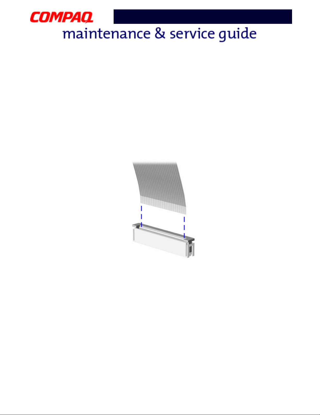
ZIF Connector
The 1800XL Notebooks use many zero insertion force (ZIF) connectors on the system
board.
CAUTION: A ZIF connector and its attached cable can be easily damaged. Handle
only the connector slide when removing or replacing a cable. Never pull or twist on
Ä
the cable while it is connected.
To remove a cable from a ZIF connector, lift both corners of the ZIF connector and slide the
cable straight out with constant light pressure.
CAUTION: When servicing these Notebooks, make sure that cables are placed in
their proper locations during the reassembly process. Improper cable placement
Ä
can damage the Notebook.
P
RESARIO NOTEBOOK MAINTENANCE AND SERVICE GUIDE
1800 S
ERIES
R
EMOVAL
& R
EPLACEMENT
3
Page 5

Presario 1800/1800T Series
Models: XL280, XL380, XL381,
and XL390
Cables
Most cables used in the Notebook are ribbon cables.
Cables must be handled with extreme care to avoid damage. Use the following precautions
when handling cables to avoid damage to the cable and the Notebook:
• Always handle cables by their connectors.
• In all cases, avoid bending, twisting, pulling, or tearing cables.
• Apply only the minimum pressure required to seat or unseat cables from their
connectors.
• Make sure that cables are routed in such a way that they cannot be caught or
snagged by parts being removed or replaced.
• Handle flex cables with extreme care; they can tear easily.
CAUTION: When servicing a Notebook, make sure that cables are placed in their
proper locations during the reassembly process. Improper cable placement can
Ä
cause severe damage to the unit.
The following illustrations show the proper placement for each cable:
• Hard Drive Ribbon Cable
• Speaker Assembly Cable
• CD/DVD Ribbon Cable • Keyboard Ribbon Cable
• Diskette Drive Ribbon Cable
4 R
EMOVAL
& R
EPLACEMENT
P
RESARIO NOTEBOOK MAINTENANCE AND SERVICE GUIDE
1800 S
ERIES
Page 6
Presario 1800/1800T Series
Models: XL280, XL380, XL381,
and XL390
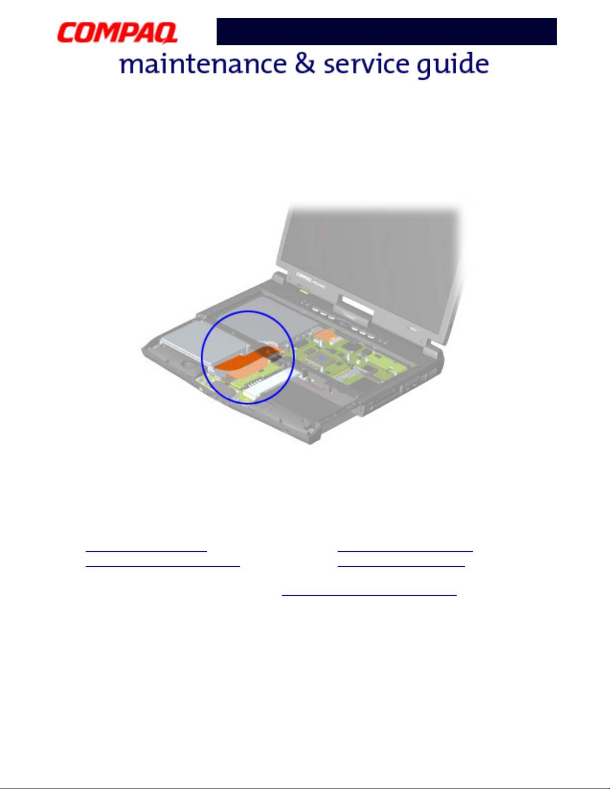
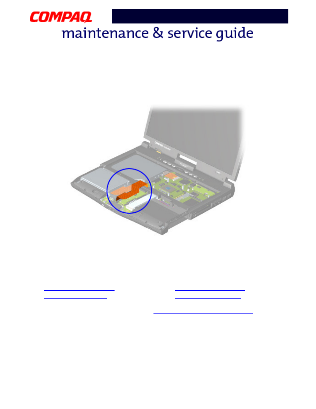
Hard Drive Ribbon Cable
The position for the hard drive ribbon cable is shown below.
CAUTION: When servicing this Notebook, make sure that cables are placed in
their proper locations during the reassembly process. Improper cable placement
Ä
can damage the Notebook.
The following illustrations show the proper placement for other cables in the unit:
• CD/DVD Ribbon Cable
• Speaker Assembly Cable
• Diskette Drive Ribbon Cable • Keyboard Ribbon Cable
To remove or replace the hard drive, see Hard Drive Removal Procedures
later in this
chapter.
P
RESARIO NOTEBOOK MAINTENANCE AND SERVICE GUIDE
1800 S
ERIES
R
EMOVAL
& R
EPLACEMENT
5
Page 7
Presario 1800/1800T Series
Models: XL280, XL380, XL381,
and XL390
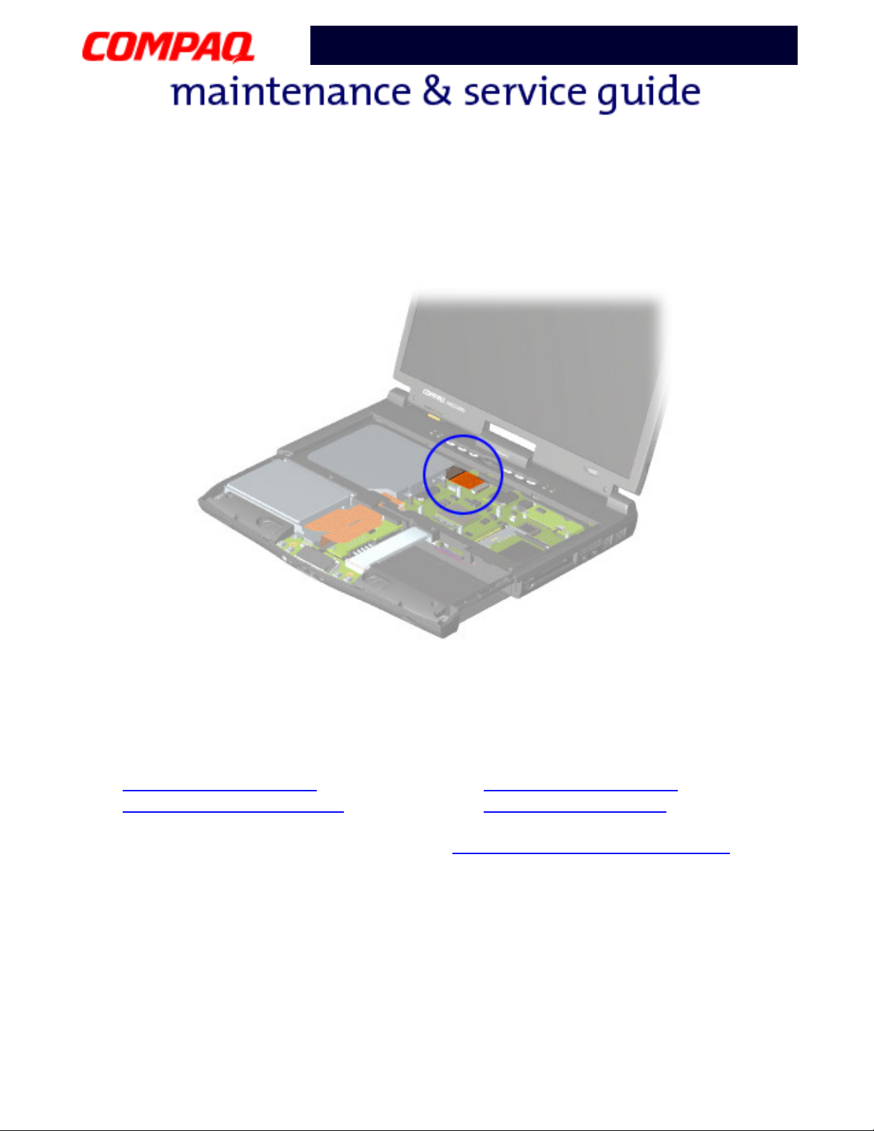
CD/DVD Ribbon Cable
The position for the CD/DVD drive ribbon cable is shown below.
CAUTION: When servicing this Notebook, make sure that cables are placed in
their proper locations during the reassembly process. Improper cable placement
Ä
can damage the Notebook.
The following illustrations show the proper placement for other cables in the unit:
• Hard Drive Ribbon Cable
• Speaker Assembly Cable
• Diskette Drive Ribbon Cable • Keyboard Ribbon Cable
To remove or replace the CD or DVD drive, see CD/DVD Drive Removal Procedures
this chapter.
6 R
EMOVAL
& R
EPLACEMENT
P
RESARIO NOTEBOOK MAINTENANCE AND SERVICE GUIDE
later in
1800 S
ERIES
Page 8
Presario 1800/1800T Series
Models: XL280, XL380, XL381,
and XL390
Diskette Drive Ribbon Cable
The position for the diskette drive ribbon cable is shown below.
CAUTION: When servicing this Notebook, make sure that cables are placed in
their proper locations during the reassembly process. Improper cable placement
Ä
can damage the Notebook.
The following illustrations show the proper placement for other cables in the unit:
• Hard Drive Ribbon Cable
• Speaker Assembly Cable
• CD/DVD Ribbon Cable • Keyboard Ribbon Cable
To remove or replace the diskette drive, see Diskette Drive Removal Procedures
later in this
chapter.
P
RESARIO NOTEBOOK MAINTENANCE AND SERVICE GUIDE
1800 S
ERIES
R
EMOVAL
& R
EPLACEMENT
7
Page 9

Presario 1800/1800T Series
Models: XL280, XL380, XL381,
and XL390
Speaker Assembly Cable
The position for the speaker assembly cable is shown below. The cable is routed under the
battery charger board and under the edge of the system board.
CAUTION: When servicing the Notebook, make sure that cables are placed in
their proper locations during the reassembly process. Improper cable placement
Ä
can damage the Notebook.
The following illustrations show the proper placement for other cables in the unit:
• Hard Drive Ribbon Cable
• Diskette Drive Ribbon Cable
• CD/DVD Ribbon Cable • Keyboard Ribbon Cable
To remove or replace the speaker assembly, see Speaker Assembly Removal Procedures
later in this chapter.
8 R
EMOVAL
& R
EPLACEMENT
P
RESARIO NOTEBOOK MAINTENANCE AND SERVICE GUIDE
1800 S
ERIES
Page 10
Presario 1800/1800T Series
Models: XL280, XL380, XL381,
and XL390
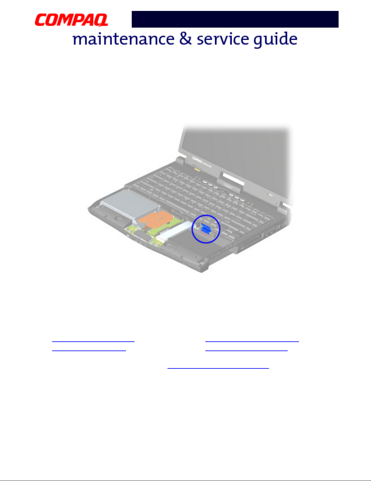
Keyboard Ribbon Cable
The position for the keyboard ribbon cable is shown below.
CAUTION: When servicing the Notebook, make sure that cables are placed in
their proper locations during the reassembly process. Improper cable placement
Ä
can damage the Notebook.
The following illustrations show the proper placement for other cables in the unit:
• Hard Drive Ribbon Cable
• Diskette Drive Ribbon Cable
• CD/DVD Ribbon Cable • Speaker Assembly Cable
To remove or replace the keyboard, see Keyboard Removal Procedures
P
RESARIO NOTEBOOK MAINTENANCE AND SERVICE GUIDE
1800 S
ERIES
later in this chapter.
R
EMOVAL
& R
EPLACEMENT
9
Page 11

Presario 1800/1800T Series
Models: XL280, XL380, XL381,
and XL390
Preparing the Notebook for Disassembly
Before beginning the removal or replacement of any Notebook components, complete the
following steps:
1. Disconnect AC power source and any external devices.
2. Disconnect the Notebook from the QuikDock (pg 11
3. Remove any PC cards.
4. Remove the battery pack (pg 12
Important: The battery pack should be removed before performing any internal
maintenance on the Notebook.
CAUTION: Metal objects can damage the battery pack as well as the battery
contacts in the battery compartment. To prevent damage, do not allow metal
Ä
objects to touch the battery contacts. Place only the battery pack for the Compaq
Presario 1800 Series Notebooks in the battery compartment. Do not force the
battery pack into the bay if insertion is difficult.
CAUTION: Do not crush, puncture, or incinerate the battery pack. Do not open a
battery pack; this damages the pack, makes it unusable, and exposes potentially
Ä
harmful battery components. No field-serviceable parts are located inside the
battery pack.
Note: The Compaq Presario 1800 Series Notebooks have several screws of various
sizes that are not interchangeable. Care must be taken during reassembly to
ensure that the correct screws are used in their correct locations. During removal,
keep screws with their associated subassembly.
).
).
10 R
EMOVAL
Important: As each component is removed from the Notebook, place the it
together with its screws away from the work area to prevent damage.
& R
EPLACEMENT
P
RESARIO NOTEBOOK MAINTENANCE AND SERVICE GUIDE
1800 S
ERIES
Page 12
Presario 1800/1800T Series
Models: XL280, XL380, XL381,
and XL390
Removal Procedures
This section outlines the removal and replacement of each component of the 1800XL Series
Notebooks. To prepare the Notebook for disassembly, refer to the previous sections of this
chapter.
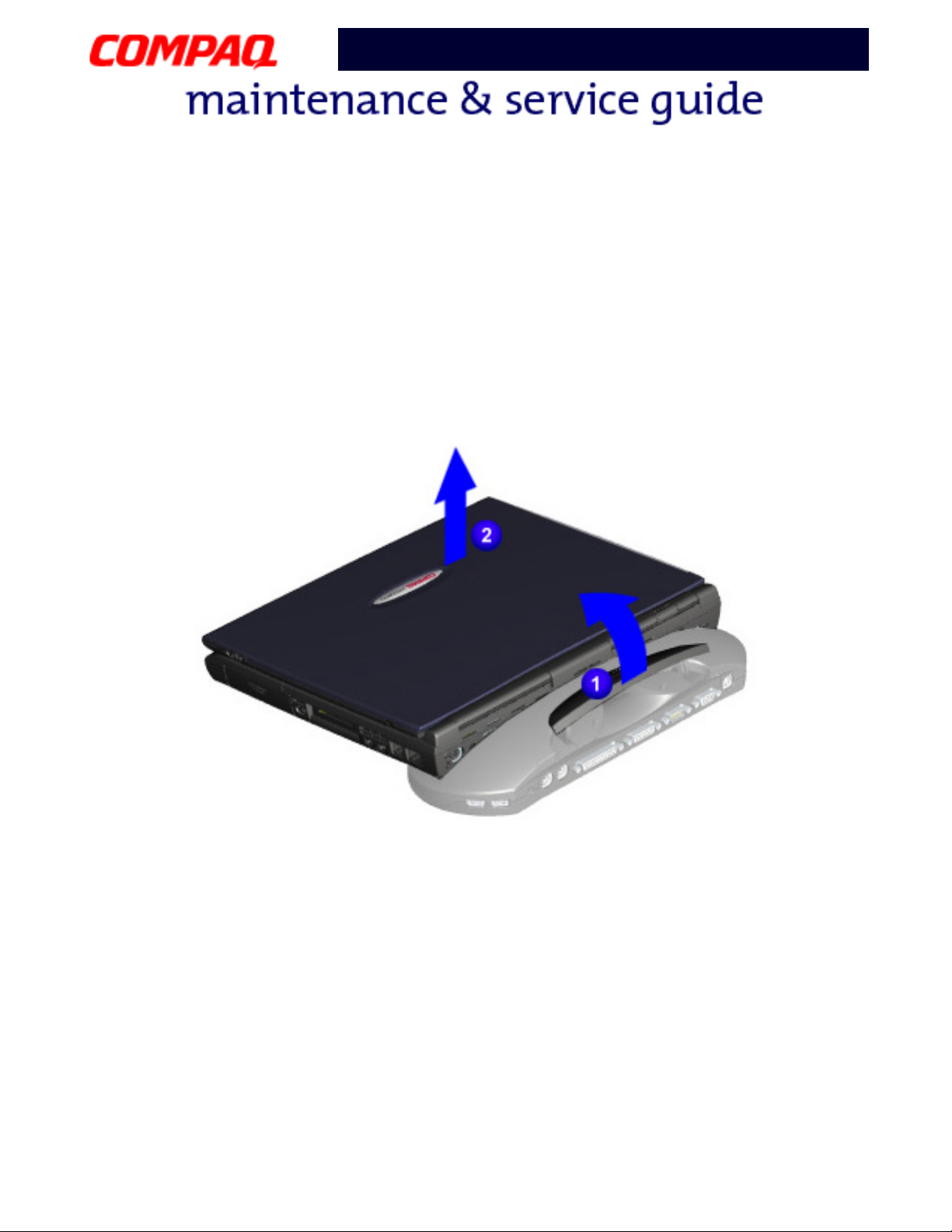
QuikDock
To disconnect from the QuikDock, lift the handle on top of the QuikDock to release the
Notebook and lift the Notebook straight up.
P
RESARIO NOTEBOOK MAINTENANCE AND SERVICE GUIDE
1800 S
ERIES
R
EMOVAL
& R
EPLACEMENT
11
Page 13
Presario 1800/1800T Series
Models: XL280, XL380, XL381,
and XL390
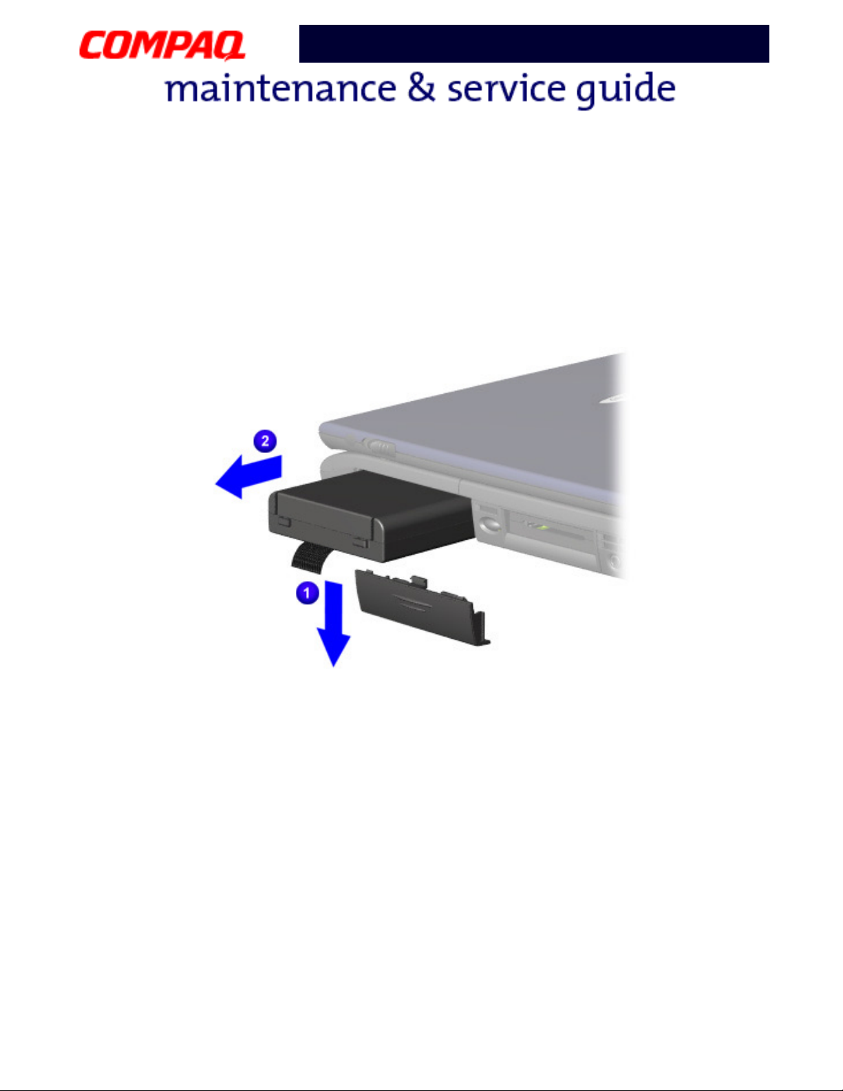
Battery Pack
To remove the battery pack, complete the following steps:
1. Slide the battery pack compartment door down and remove it from the chassis
2. Pull the battery pack from the chassis by the tab located on the end of the battery
2
pack
.
1
.
To replace the battery pack, reverse these procedures.
Important: The battery pack should be removed before performing any internal
maintenance on the Notebook.
CAUTION: Metal objects can damage the battery pack as well as the battery
contacts in the battery compartment. To prevent damage, do not allow metal
Ä
objects to touch the battery contacts. Place only the battery pack for the Compaq
Presario 1800 Series Portable Notebooks into the battery compartment. Do not
force the battery pack into the bay if insertion does not occur easily.
CAUTION: Do not crush, puncture, or incinerate the battery pack. Do not open a
battery pack; this damages the pack, makes it unusable, and exposes potentially
Ä
harmful battery components. No field-serviceable parts are located inside the
battery pack.
12 R
EMOVAL
& R
EPLACEMENT
P
RESARIO NOTEBOOK MAINTENANCE AND SERVICE GUIDE
1800 S
ERIES
Page 14
Presario 1800/1800T Series
Models: XL280, XL380, XL381,
and XL390
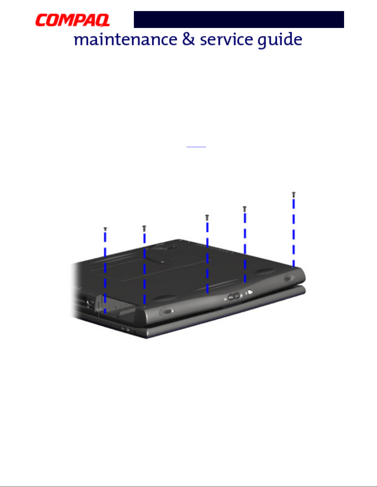
Palmrest Cover with TouchPad
Note: It is not necessary to remove the display panel assembly to access the interior
components of the Notebook.
To remove the Palmrest cover with TouchPad, complete the following steps:
1. Prepare the Notebook for disassembly (pg 10
).
2. Close the display and turn the Notebook upside down.
3. Remove four screws from the bottom of the Notebook, and one from the battery
compartment.
Continued on the next page.
P
RESARIO NOTEBOOK MAINTENANCE AND SERVICE GUIDE
1800 S
ERIES
R
EMOVAL
& R
EPLACEMENT
13
Page 15
Presario 1800/1800T Series
Models: XL280, XL380, XL381,
and XL390
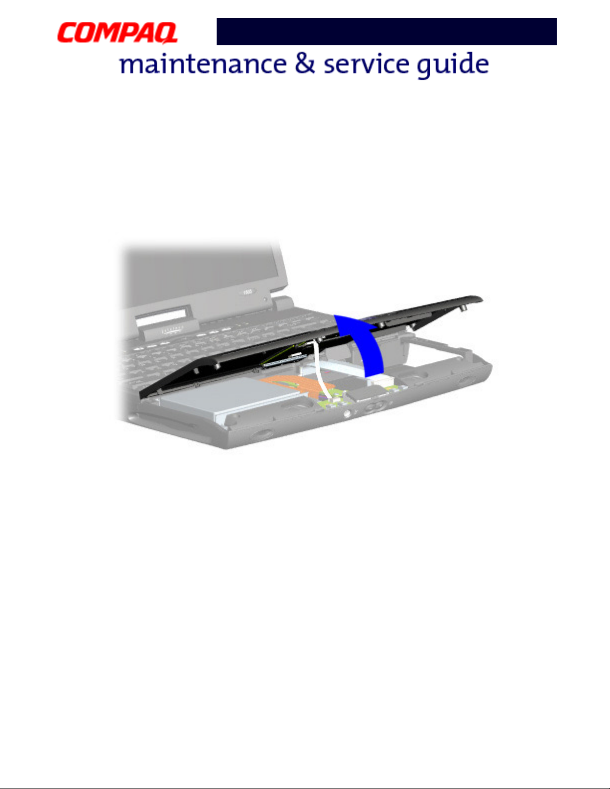
4. Turn the Notebook right side up and open the display.
5. Lift up the front end of the Palmrest cover.
Note: It may be necessary to apply pressure on the sides of the Palmrest cover to
release it from the chassis.
Continued on the next page.
14 R
EMOVAL
& R
EPLACEMENT
P
RESARIO NOTEBOOK MAINTENANCE AND SERVICE GUIDE
1800 S
ERIES
Page 16
Presario 1800/1800T Series
Models: XL280, XL380, XL381,
and XL390
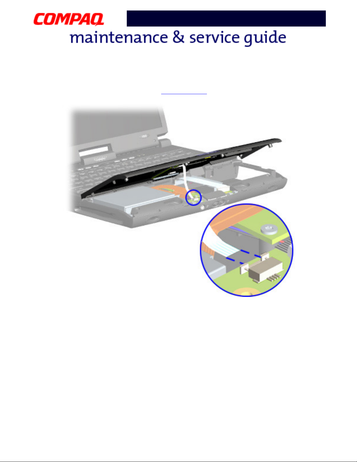
6. Disconnect the flex cable from the ZIF Connector on the DisqPlay module.
To replace the Palmrest cover with TouchPad, reverse these procedures.
P
RESARIO NOTEBOOK MAINTENANCE AND SERVICE GUIDE
1800 S
ERIES
R
EMOVAL
& R
EPLACEMENT
15
Page 17
Presario 1800/1800T Series
Models: XL280, XL380, XL381,
and XL390
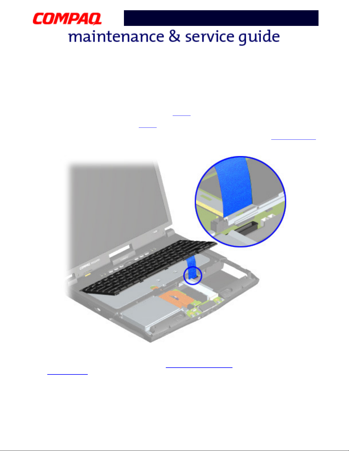
Keyboard
To remove the keyboard, complete the following steps:
1. Prepare the Notebook for disassembly (pg 10
2. Remove the Palmrest cover (pg 13
).
).
3. Gently lift the front of the keyboard, disconnect the flex cable from the ZIF Connector
on the system board, and remove the keyboard.
To replace the keyboard, reverse these procedures.
Note: When replacing the keyboard, the Keyboard Ribbon Cable should fold behind the
ZIF Connector
16 R
EMOVAL
& R
EPLACEMENT
and not underneath the keyboard.
P
RESARIO NOTEBOOK MAINTENANCE AND SERVICE GUIDE
1800 S
ERIES
Page 18

Presario 1800/1800T Series
Models: XL280, XL380, XL381,
and XL390
Button Board Cover
(Internet Zone and Status Lights)
Note: Illustrations may show parts removed that are not part of this procedure. It is
necessary to remove only the parts listed in the written procedure.
To remove the button board cover, complete the following steps:
1. Prepare the Notebook for disassembly (pg 10
).
2. Open the display and squeeze the sides of the display assembly hinge covers while
sliding them off the hinges.
Continued on the next page.
P
RESARIO NOTEBOOK MAINTENANCE AND SERVICE GUIDE
1800 S
ERIES
R
EMOVAL
& R
EPLACEMENT
17
Page 19

Presario 1800/1800T Series
Models: XL280, XL380, XL381,
and XL390
3. Remove the two innermost screws from the display assembly hinges that secure the
button board cover to the chassis.
Continued on the next page.
18 R
EMOVAL
& R
EPLACEMENT
P
RESARIO NOTEBOOK MAINTENANCE AND SERVICE GUIDE
1800 S
ERIES
Page 20

Presario 1800/1800T Series
Models: XL280, XL380, XL381,
and XL390
4. Turn the unit upside down and remove the two screws (shown below) located near the
back that secure the button board cover to the chassis.
Continued on the next page.
P
RESARIO NOTEBOOK MAINTENANCE AND SERVICE GUIDE
1800 S
ERIES
R
EMOVAL
& R
EPLACEMENT
19
Page 21

Presario 1800/1800T Series
Models: XL280, XL380, XL381,
and XL390
5. Turn the unit right side up and open the display.
6. Lift up one corner of the button board cover and push forward from the back (center
1
piece) to release the snaps
7. Lift and remove the cover from the chassis
.
2
.
To replace the button board cover, reverse these procedures.
20 R
EMOVAL
& R
EPLACEMENT
P
RESARIO NOTEBOOK MAINTENANCE AND SERVICE GUIDE
1800 S
ERIES
Page 22

Presario 1800/1800T Series
Models: XL280, XL380, XL381,
and XL390
Internet Switch Board
Note: Illustrations may show parts removed that are not part of this procedure. It is
necessary to remove only the parts listed in the written procedure.
To remove the Internet switch board, complete the following steps:
1. Prepare the Notebook for disassembly (pg 10
2. Remove the button board cover (pg 17
).
).
3. Remove the screw securing the display flex cable bracket and lift off the bracket
2
4. Disconnect the display flex cable from the connector on the system board
.
5. Disconnect the backlight cable from the connector on the Internet switch board
3
1
.
.
Continued on the next page.
P
RESARIO NOTEBOOK MAINTENANCE AND SERVICE GUIDE
1800 S
ERIES
R
EMOVAL
& R
EPLACEMENT
21
Page 23

Presario 1800/1800T Series
Models: XL280, XL380, XL381,
and XL390
6. Remove the two screws securing the Internet switch board and lift it from the chassis.
Note: The 15-in. standard and high resolution (SXGA) display panels have unique
Internet switch boards that are not interchangeable. If disassembling more than one
Notebook, keep each Internet switch board with the correct Notebook.
To replace the Internet switch board, reverse these procedures.
22 R
EMOVAL
& R
EPLACEMENT
P
RESARIO NOTEBOOK MAINTENANCE AND SERVICE GUIDE
1800 S
ERIES
Page 24

Presario 1800/1800T Series
Models: XL280, XL380, XL381,
and XL390
Heat Sink (Heatspreader)
To remove the heat sink, complete the following steps:
1. Prepare the Notebook for disassembly (pg 10
2. Remove the Palmrest cover with TouchPad (pg 13
3. Remove the keyboard (pg 16
).
).
).
4. Remove six screws from the heat sink and lift it out of the chassis.
To replace the heat sink, reverse these procedures.
CAUTION: To prevent damage, do not use excessive pressure when replacing
screws.
Ä
Note: If the thermal pads on the heat sink are missing or damaged, install a new
heat sink.
Important: Before installing the new heat sink, remove the plastic covering from
the thermal pads.
P
RESARIO NOTEBOOK MAINTENANCE AND SERVICE GUIDE
1800 S
ERIES
R
EMOVAL
& R
EPLACEMENT
23
Page 25

Presario 1800/1800T Series
Models: XL280, XL380, XL381,
and XL390
Modem
To remove the modem, complete the following steps:
1. Prepare the Notebook for disassembly (pg 10
2. Remove the Palmrest cover with TouchPad (pg 13
3. Remove the keyboard (pg 16
4. Remove the button board cover (pg 17
5. Remove the heat sink (pg 23
).
).
).
6. Disconnect the modem cable from the connector on the modem board
).
).
1
.
7. Remove the three screws from the modem board and remove the modem by lifting
the front edge, sliding it towards you, and then lifting the modem off the system
2
board
Note: The CPU cover prevents lifting the modem straight up from the system board.
.
To replace the modem board, reverse these procedures.
24 R
EMOVAL
& R
EPLACEMENT
P
RESARIO NOTEBOOK MAINTENANCE AND SERVICE GUIDE
1800 S
ERIES
Page 26

Presario 1800/1800T Series
Models: XL280, XL380, XL381,
and XL390
Hard Drive
Note: Illustrations may show parts removed that are not part of this procedure. It is
necessary to remove only the parts listed in the written procedure.
To remove the hard drive, complete the following steps:
1. Prepare the Notebook for disassembly (pg 10
2. Remove the Palmrest cover with TouchPad (pg 13
3. Disconnect the hard drive data cable
.
).
).
Note: Do not pull on the ribbon cable. Remove the cable from the back of the hard drive
using the plastic connector attached to the cable.
Continued on the next page.
P
RESARIO NOTEBOOK MAINTENANCE AND SERVICE GUIDE
1800 S
ERIES
R
EMOVAL
& R
EPLACEMENT
25
Page 27

Presario 1800/1800T Series
Models: XL280, XL380, XL381,
and XL390
4. Remove three screws from the hard drive mounting bracket.
5. Lift out the hard drive with drive mounting brackets attached.
CAUTION: The hard drive unit is susceptible to shock and must not be dropped or
allowed to experience any rough treatment. Handle the hard drive with extreme
Ä
care.
Continued on the next page.
26 R
EMOVAL
& R
EPLACEMENT
P
RESARIO NOTEBOOK MAINTENANCE AND SERVICE GUIDE
1800 S
ERIES
Page 28

Presario 1800/1800T Series
Models: XL280, XL380, XL381,
and XL390
6. To remove the hard drive mounting brackets, remove the two screws from each of
side of the hard drive.
To replace the hard drive and mounting brackets, reverse these procedures.
P
RESARIO NOTEBOOK MAINTENANCE AND SERVICE GUIDE
1800 S
ERIES
R
EMOVAL
& R
EPLACEMENT
27
Page 29

Presario 1800/1800T Series
Models: XL280, XL380, XL381,
and XL390
LCD DisqPlay Module
Note: Illustrations may show parts removed that are not part of this procedure. It is
necessary to remove only the parts listed in the written procedure.
To remove the LCD DisqPlay Module, complete the following steps:
1. Prepare the Notebook for disassembly (pg 10
2. Remove the Palmrest cover with TouchPad (pg 13
3. Remove the hard drive (pg 25
).
4. Disconnect the flex cable from the DisqPlay module
).
).
1
5. Lift and remove the DisqPlay module from the chassis
.
2
.
To replace the LCD DisqPlay module, reverse these procedures.
28 R
EMOVAL
& R
EPLACEMENT
P
RESARIO NOTEBOOK MAINTENANCE AND SERVICE GUIDE
1800 S
ERIES
Page 30

Presario 1800/1800T Series
Models: XL280, XL380, XL381,
and XL390
Processor
To remove the processor, complete the following steps:
1. Prepare the Notebook for disassembly (pg 10
2. Remove the Palmrest cover with TouchPad (pg 13
3. Remove the keyboard (pg 16
4. Remove the heat sink (pg 23
).
).
).
).
Note: These Notebooks are equiped with one of two different types of processors. Match
the processor in the unit with the correct procedure before attempting to remove it.
5. If the processor matches the image below, complete step a. However, if the processor
matches the image shown on the next page, skip to step b.
a. Place tip of standard screwdriver in center slot, twist screwdriver toward “Free”
1
until it snaps
, and lift processor from the chassis 2.
Continued on the next page.
P
RESARIO NOTEBOOK MAINTENANCE AND SERVICE GUIDE
1800 S
ERIES
R
EMOVAL
& R
EPLACEMENT
29
Page 31

Presario 1800/1800T Series
Models: XL280, XL380, XL381,
and XL390
b. With standard screwdriver, turn screw counter-clockwise toward “0” 1 and lift
processor from the chassis
2
.
To replace the processor, complete the following steps:
1. Fully align the processor pins with the socket holes on the connector.
2. Press down carefully on the processor directly over the connector to seat the it.
3. Once the processor is in place, reassemble the remaining subassemblies by reversing
their removal procedures.
30 R
EMOVAL
& R
EPLACEMENT
P
RESARIO NOTEBOOK MAINTENANCE AND SERVICE GUIDE
1800 S
ERIES
Page 32

Presario 1800/1800T Series
Models: XL280, XL380, XL381,
and XL390
CD, CD-RW, or DVD Drive
To remove the CD, CD-RW, or DVD Drive, complete the following steps:
1. Prepare the Notebook for disassembly (pg 10
2. Remove the Palmrest cover with TouchPad (pg 13
3. Remove the keyboard (pg 16
4. Remove the heat sink (pg 23
).
).
).
).
5. Turn the unit upside down and remove the two screws that secure the CD/DVD drive
to the chassis.
Continued on the next page.
P
RESARIO NOTEBOOK MAINTENANCE AND SERVICE GUIDE
1800 S
ERIES
R
EMOVAL
& R
EPLACEMENT
31
Page 33

Presario 1800/1800T Series
Models: XL280, XL380, XL381,
and XL390
6. Turn the unit over (right side up) and open the display.
7. Remove the two screws located at the back of the CD/DVD drive.
Continued on the next page.
32 R
EMOVAL
& R
EPLACEMENT
P
RESARIO NOTEBOOK MAINTENANCE AND SERVICE GUIDE
1800 S
ERIES
Page 34

Presario 1800/1800T Series
Models: XL280, XL380, XL381,
and XL390
8. Disconnect the CD/DVD drive cable and push forward from the back of the drive to
slide it out of the chassis.
To replace the CD, CD-RW, or DVD drive, reverse these procedures.
CAUTION: When replacing the CD/DVD drive, ensure that the
CD/DVD Ribbon Cable is placed in its proper location during the reassembly
Ä
process. Improper cable placement can damage the Notebook.
P
RESARIO NOTEBOOK MAINTENANCE AND SERVICE GUIDE
1800 S
ERIES
R
EMOVAL
& R
EPLACEMENT
33
Page 35

Presario 1800/1800T Series
Models: XL280, XL380, XL381,
and XL390
Display Panel Assembly
Note: Illustrations may show parts removed that are not part of this procedure. It is
necessary to remove only the parts listed in the written procedure.
To remove the display panel assembly, complete the following steps:
1. Prepare the Notebook for disassembly (pg 10
2. Remove the button board cover (pg 17
).
).
3. Remove the screw securing the display flex cable bracket and lift off the bracket
2
4. Disconnect the display flex cable from the connector on the system board
.
5. Disconnect the backlight cable from the connector on the Internet switch board
3
1
.
.
Continued on the next page.
34 R
EMOVAL
& R
EPLACEMENT
P
RESARIO NOTEBOOK MAINTENANCE AND SERVICE GUIDE
1800 S
ERIES
Page 36

Presario 1800/1800T Series
Models: XL280, XL380, XL381,
and XL390
6. Remove the two outermost screws from the display assembly hinges.
CAUTION: Support the display while removing the screws to prevent dropping
and damaging the display.
Ä
Continued on the next page.
P
RESARIO NOTEBOOK MAINTENANCE AND SERVICE GUIDE
1800 S
ERIES
R
EMOVAL
& R
EPLACEMENT
35
Page 37

Presario 1800/1800T Series
Models: XL280, XL380, XL381,
and XL390
7. Lift the display assembly off the hinges.
To replace the display panel assembly, reverse these procedures.
36 R
EMOVAL
& R
EPLACEMENT
P
RESARIO NOTEBOOK MAINTENANCE AND SERVICE GUIDE
1800 S
ERIES
Page 38

Presario 1800/1800T Series
Models: XL280, XL380, XL381,
and XL390
Upper CPU Cover
To remove the upper CPU cover, complete the following steps:
1. Prepare the Notebook for disassembly (pg 10
2. Remove the Palmrest cover with TouchPad (pg 13
3. Remove the keyboard (pg 16
4. Remove the heat sink (pg 23
5. Remove the button board cover (pg 17
).
).
).
6. Remove the Internet switch board (pg 21
7. Remove the hard drive (pg 25
).
8. Remove the display panel assembly (pg 34
).
).
).
).
9. Remove the four screws (shown) located on the top of the upper CPU cover and lift
the cover off the chassis.
To replace the upper CPU cover, reverse these procedures.
P
RESARIO NOTEBOOK MAINTENANCE AND SERVICE GUIDE
1800 S
ERIES
R
EMOVAL
& R
EPLACEMENT
37
Page 39

Presario 1800/1800T Series
Models: XL280, XL380, XL381,
and XL390
Fan Assembly
To remove the fan assembly, complete the following steps:
1. Prepare the Notebook for disassembly (pg 10
2. Remove the Palmrest cover with TouchPad (pg 13
3. Remove the keyboard (pg 16
4. Remove the heat sink (pg 23
5. Remove the button board cover (pg 17
).
).
).
6. Remove the Internet switch board (pg 21
7. Remove the display panel assembly (pg 34
8. Remove the hard drive (pg 25
9. Remove the upper CPU cover (pg 37
).
).
).
).
).
).
10. Lift the fan assembly from the chassis slot, and disconnect the fan cable from the
connector on the system board.
Continued on the next page.
38 R
EMOVAL
& R
EPLACEMENT
P
RESARIO NOTEBOOK MAINTENANCE AND SERVICE GUIDE
1800 S
ERIES
Page 40

Presario 1800/1800T Series
Models: XL280, XL380, XL381,
and XL390
To remove the fan gasket, pull the gasket from the exterior of the fan.
To replace the fan assembly and gasket, reverse these procedures.
Important: When replacing the fan assembly, be sure that the side with the
manufacturer’s label is facing toward the interior of the Notebook (the fan blades should
be seen from the exterior and air should blow into the Notebook).
P
RESARIO NOTEBOOK MAINTENANCE AND SERVICE GUIDE
1800 S
ERIES
R
EMOVAL
& R
EPLACEMENT
39
Page 41

Presario 1800/1800T Series
Models: XL280, XL380, XL381,
and XL390
Real Time Clock (RTC) Battery
CAUTION: Removing the RTC battery clears the power-on password and removes
all setup attributes that are programmed in the CMOS.
Ä
To remove the RTC battery, complete the following steps:
1. Prepare the Notebook for disassembly (pg 10
2. Remove the Palmrest cover with TouchPad (pg 13
3. Remove the keyboard (pg 16
4. Remove the heat sink (pg 23
5. Remove the button board cover (pg 17
6. Remove the Internet switch board (pg 21
7. Remove the display panel assembly (pg 34
8. Remove the hard drive (pg 25
9. Remove the upper CPU cover (pg 37
).
).
).
).
).
).
).
Continued on the next page.
).
).
40 R
EMOVAL
& R
EPLACEMENT
P
RESARIO NOTEBOOK MAINTENANCE AND SERVICE GUIDE
1800 S
ERIES
Page 42

Presario 1800/1800T Series
Models: XL280, XL380, XL381,
and XL390
10. Locate the RTC battery on the system board to the right of the CD/DVD drive near the
rear edge of the chassis.
1
11. Using your fingers or a non-metallic object, gently pry up the RTC battery
out of the battery socket
2
.
and lift it
Note: If you are clearing the CMOS attributes, keep the battery out for at least 10
seconds before replacing it.
To replace the RTC battery, press the battery firmly into the socket, and reassemble the
remaining components by reversing their removal procedures.
P
RESARIO NOTEBOOK MAINTENANCE AND SERVICE GUIDE
1800 S
ERIES
R
EMOVAL
& R
EPLACEMENT
41
Page 43

Presario 1800/1800T Series
Models: XL280, XL380, XL381,
and XL390
Diskette Drive
To remove the diskette drive, complete the following steps:
1. Prepare the Notebook for disassembly (pg 10
2. Remove the Palmrest cover with TouchPad (pg 13
3. Remove the keyboard (pg 16
4. Remove the heat sink (pg 23
).
).
5. Remove the CD, CD-RW or DVD Drive (pg 31
6. Remove the button board cover (pg 17
).
7. Remove the Internet switch board (pg 21
8. Remove the display panel assembly (pg 34
9. Remove the hard drive (pg 25
10. Remove the upper CPU cover (pg 37
).
).
).
).
).
).
).
11. Remove screw from the diskette drive retaining bracket and lift off the bracket.
Continued on the next page.
42 R
EMOVAL
& R
EPLACEMENT
P
RESARIO NOTEBOOK MAINTENANCE AND SERVICE GUIDE
1800 S
ERIES
Page 44

Presario 1800/1800T Series
Models: XL280, XL380, XL381,
and XL390
12. Disconnect the diskette drive data cable from the ZIF Connector on the system
board
13. Remove the screw that secures the diskette drive to the chassis, and lift the drive
from the chassis
1
.
2
.
To replace the diskette drive, reverse these procedures.
CAUTION: When replacing the diskette drive, make sure that the
Diskette Drive Ribbon Cable is placed in its proper location during the reassembly
Ä
process. Improper cable placement can damage the Notebook.
P
RESARIO NOTEBOOK MAINTENANCE AND SERVICE GUIDE
1800 S
ERIES
R
EMOVAL
& R
EPLACEMENT
43
Page 45

Presario 1800/1800T Series
Models: XL280, XL380, XL381,
and XL390
Voltage Converter Board
To remove the voltage converter board, complete the following steps:
1. Prepare the Notebook for disassembly (pg 10
2. Remove the Palmrest cover with TouchPad (pg 13
3. Remove the keyboard (pg 16
4. Remove the heat sink (pg 23
5. Remove the button board cover (pg 17
).
).
).
6. Remove the Internet switch board (pg 21
7. Remove the display panel assembly (pg 34
8. Remove the hard drive (pg 25
9. Remove the upper CPU cover (pg 37
).
).
).
).
).
).
10. Remove the two screws (shown below) securing the voltage converter board.
11. Lift the voltage converter board off the connector on the system board.
Note: Retain the plastic insulator for reassembly with the replacement board.
To replace the voltage converter board, reverse these procedures.
Note: When replacing the voltage converter board, ensure that the pins are aligned with
the connector on the system board.
44 R
EMOVAL
& R
EPLACEMENT
P
RESARIO NOTEBOOK MAINTENANCE AND SERVICE GUIDE
1800 S
ERIES
Page 46

Presario 1800/1800T Series
Models: XL280, XL380, XL381,
and XL390
Speaker Assembly
To remove the speaker assembly, complete the following steps:
1. Prepare the Notebook for disassembly (pg 10
2. Remove the Palmrest cover with TouchPad (pg 13
3. Remove the keyboard (pg 16
4. Remove the heat sink (pg 23
5. Remove the button board cover (pg 17
6. Remove the Internet switch board (pg 21
7. Remove the display panel assembly (pg 34
8. Remove the hard drive (pg 25
9. Remove the upper CPU cover (pg 37
).
).
).
).
).
).
).
10. Remove the voltage converter board (pg 44
Continued on the next page.
).
).
).
P
RESARIO NOTEBOOK MAINTENANCE AND SERVICE GUIDE
1800 S
ERIES
R
EMOVAL
& R
EPLACEMENT
45
Page 47

Presario 1800/1800T Series
Models: XL280, XL380, XL381,
and XL390
11. Disconnect the speaker cables from the system board and lift the speaker assembly
from the chassis.
To replace the speaker assembly, reverse these procedures.
CAUTION: When replacing the diskette drive, make sure that the
Speaker Assembly Cable is placed in its proper location during the reassembly
Ä
process. Improper cable placement can damage the Notebook.
46 R
EMOVAL
& R
EPLACEMENT
P
RESARIO NOTEBOOK MAINTENANCE AND SERVICE GUIDE
1800 S
ERIES
Page 48

Presario 1800/1800T Series
Models: XL280, XL380, XL381,
and XL390
System Board
To remove the system board, complete the following steps:
1. Prepare the Notebook for disassembly (pg 10
2. Remove the Palmrest cover with TouchPad (pg 13
3. Remove the keyboard (pg 16
4. Remove the heat sink (pg 23
5. Remove the button board cover (pg 17
).
).
).
6. Remove the Internet switch board (pg 21
7. Remove the display panel assembly (pg 34
8. Remove the hard drive (pg 25
9. Remove the upper CPU cover (pg 37
).
).
).
).
).
).
10. Disconnect the LCD DisqPlay module cable from the system board (pg 28
11. Remove the modem (pg 24
12. Remove the CD, CD-RW, or DVD drive (pg 31
13. Remove the fan assembly (pg 38
14. Disconnect the diskette drive cable from the system board (pg 43
).
).
).
).
).
15. Remove the voltage converter board (pg 44
).
16. Disconnect the speaker assembly cables from the system board (pg 46
Continued on the next page.
P
RESARIO NOTEBOOK MAINTENANCE AND SERVICE GUIDE
1800 S
ERIES
R
EMOVAL
).
& R
EPLACEMENT
47
Page 49

Presario 1800/1800T Series
Models: XL280, XL380, XL381,
and XL390
17. Remove five standoffs (shown below) from the system board.
Note: The four remaining standoffs located on the system board may be left in place.
Continued on the next page.
48 R
EMOVAL
& R
EPLACEMENT
P
RESARIO NOTEBOOK MAINTENANCE AND SERVICE GUIDE
1800 S
ERIES
Page 50

Presario 1800/1800T Series
Models: XL280, XL380, XL381,
and XL390
18. Remove the two screws from the CD/DVD drive mounting rail, and lift the mounting
rail from the system board.
Continued on the next page.
P
RESARIO NOTEBOOK MAINTENANCE AND SERVICE GUIDE
1800 S
ERIES
R
EMOVAL
& R
EPLACEMENT
49
Page 51

Presario 1800/1800T Series
Models: XL280, XL380, XL381,
and XL390
19. Remove four screws (shown below) from the system board.
Note: The edges of the system board may be secured by shielded tape. This tape must
be removed to free the system board.
Continued on the next page.
50 R
EMOVAL
& R
EPLACEMENT
P
RESARIO NOTEBOOK MAINTENANCE AND SERVICE GUIDE
1800 S
ERIES
Page 52

Presario 1800/1800T Series
Models: XL280, XL380, XL381,
and XL390
20. Make sure that the PC card eject button is pushed inward 1, and then lift up the front
of the system board and pull it forward to remove it from the chassis
2
.
Important: Before replacing the system board, remove all remaining cables.
To replace the system board, reverse these procedures.
P
RESARIO NOTEBOOK MAINTENANCE AND SERVICE GUIDE
1800 S
ERIES
R
EMOVAL
& R
EPLACEMENT
51
Page 53

Presario 1800/1800T Series
Models: XL280, XL380, XL381,
and XL390
Memory Module
To remove the memory module, complete the following steps:
1. Prepare the Notebook for disassembly (pg 10
).
2. Close the display and turn the Notebook upside down.
3. Remove the screw (shown) from the memory module door.
4. With the front of the Notebook facing you, slide the memory module door to the left
and lift it off.
Continued on the next page.
52 R
EMOVAL
& R
EPLACEMENT
P
RESARIO NOTEBOOK MAINTENANCE AND SERVICE GUIDE
1800 S
ERIES
Page 54

Presario 1800/1800T Series
Models: XL280, XL380, XL381,
and XL390
5. Pull the side levers to release the memory 1, and lift the memory module from the
system board
2
.
To replace the memory module, reverse these procedures.
P
RESARIO NOTEBOOK MAINTENANCE AND SERVICE GUIDE
1800 S
ERIES
R
EMOVAL
& R
EPLACEMENT
53
 Loading...