

Page 1

Please check out our eBay auctions for more great
deals on Factory Service Manuals:
Page 2
Presario 1400 Series
Model XL240, XL241, XL242, XL244, XL245, XL246, XL247, XL250, XL340,
XL341, XL342, XL343, XL344, XL345, XL346, XL350, XL352, XL355, and XL356
Removal Sequence
This section describes the removal and replacement process for the Presario 1400 Series Notebook.
The procedures are divided into two subsections: The Customer Removable Parts and The Service
Removable Parts
and the second subsection explains which parts should be serviced by the technician.
. The first subsection explains which parts may be removed by the customer/owner,
The Customer Removable Parts
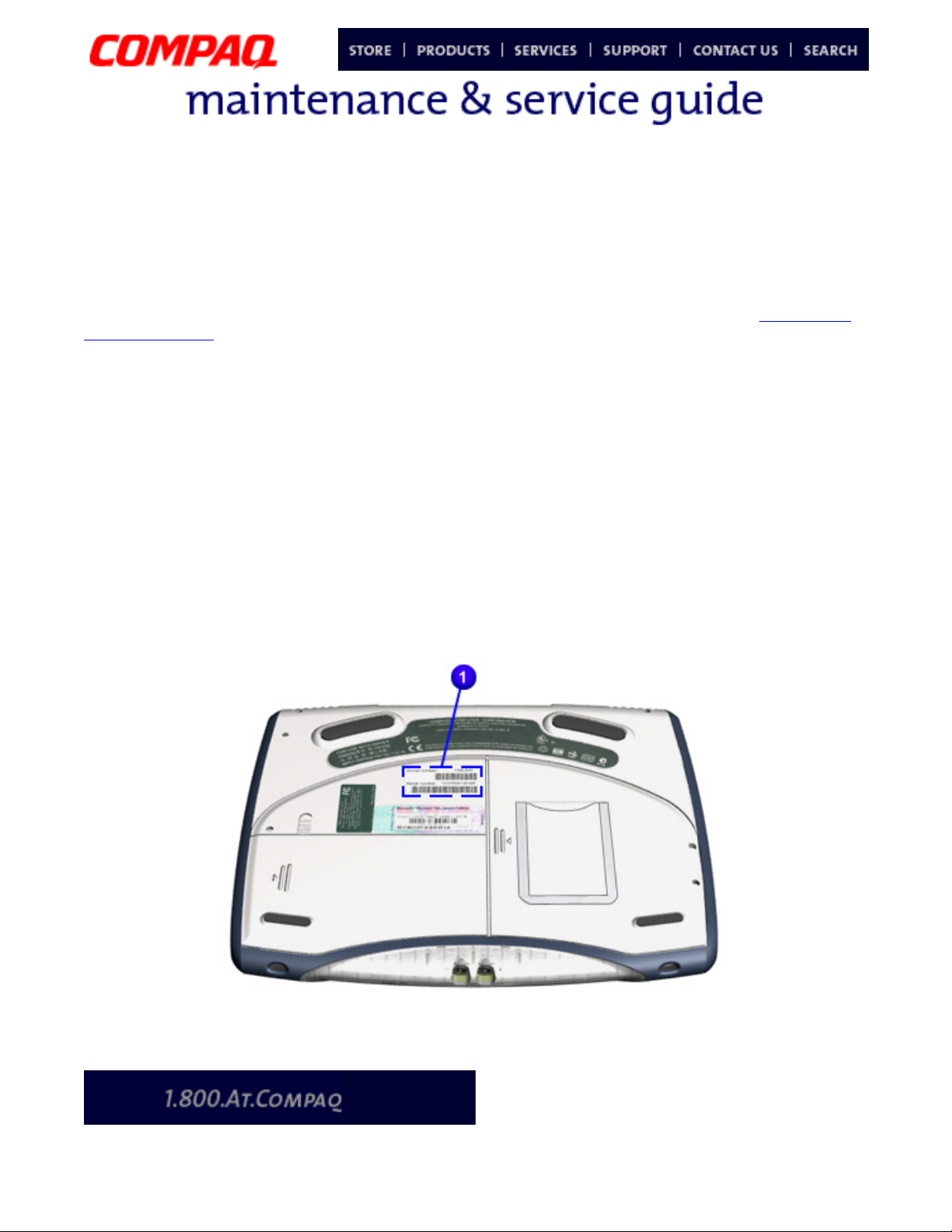
Serial Number
Report your Notebook’s serial number 1 to Compaq when requesting information or ordering spare
parts. The serial number is located on the underside of the Notebook as shown below.
WARNING: Prior to servicing your Notebook, disconnect AC power cords and
Å
external devices, and remove the battery pack and any PC Cards. Failure to
disconnect electrical devices may cause damage to the Notebook and loss of
human life.
P
RESARIO NOTEBOOK MAINTENANCE AND SERVICE GUIDE
1400 S
ERIES
R
EMOVAL SEQUENCE
1
Page 3
Presario 1400 Series
Model XL240, XL241, XL242, XL244, XL245, XL246, XL247, XL250, XL340,
XL341, XL342, XL343, XL344, XL345, XL346, XL350, XL352, XL355, and XL356
Electrostatic Discharge
A sudden discharge of static electricity from a finger or other conductor can destroy static-sensitive
devices or microcircuitry. Often the spark is neither felt nor heard, but damage occurs. An electronic
device that has been exposed to electrostatic discharge (ESD) may not seem to be affected and
work perfectly throughout a normal cycle. Although the Notebook may function normally for a period
of time, it may have been degraded in the internal layers, reducing the its life expectancy.
Networks built into many integrated circuits provide some protection, but in many cases the
discharge contains enough power to alter device parameters or melt silicon junctions.
Generating Static
The table below shows activities that generate static electricity and the associated level of
electrostatic voltage.
Typical Electrostatic Voltages
Event Relative Humidity
10% 40% 55%
Walking across carpet 35,000 V 15,000 V 7,500 V
Walking across vinyl floor 12,000 V 5,000 V 3,000 V
Motions of bench worker 6,000 V 800 V 400 V
Removing DIPS from plastic tubes 2,000 V 700 V 400 V
Removing DIPS from vinyl trays 11,500 V 4,000 V 2,000 V
Removing DIPS from Styrofoam 14,500 V 5,000 V 3,500 V
Removing bubble pack from PCBs 26,000 V 20,000 V 7,000 V
Packing PCBs in foam-lined box 21,000 V 11,000 V 5,000 V
Note: 700 volts can degrade a product.
2 R
EMOVAL SEQUENCE
P
RESARIO NOTEBOOK MAINTENANCE AND SERVICE GUIDE
1400 S
ERIES
Page 4

Presario 1400 Series
Model XL240, XL241, XL242, XL244, XL245, XL246, XL247, XL250, XL340,
XL341, XL342, XL343, XL344, XL345, XL346, XL350, XL352, XL355, and XL356
Service Considerations
During the disassembly and assembly of your Notebook, please keep in mind the considerations
listed below.
Tool and Software Requirements
Customer serviceable parts only require the following items during disassembly:
•
Small standard screwdriver
•
Small Phillips screwdriver
•
Diagnostics software
Screws
The screws used on the customer removable parts are Phillips. These screws are not
interchangeable. If an incorrect screw is applied during the reassembly process, it can damage the
unit. Compaq strongly recommends that you keep all screws with their respective parts as they are
removed during disassembly. Then replace the screws in their proper locations.
Important: As each subassembly is removed from the Notebook, place it away from the
work area to prevent damage.
Note: Screws inside the Compaq Presario 1400 Series Portable Notebooks vary in size
and are not interchangeable. During reassembly care must be taken to return the
correct screws to their original location. Keep all screws with their respective
subassembly during removal.
P
RESARIO NOTEBOOK MAINTENANCE AND SERVICE GUIDE
1400 S
ERIES
R
EMOVAL SEQUENCE
3
Page 5

Presario 1400 Series
Model XL240, XL241, XL242, XL244, XL245, XL246, XL247, XL250, XL340,
XL341, XL342, XL343, XL344, XL345, XL346, XL350, XL352, XL355, and XL356
Notebook Disassembly
Before beginning The Removal and Replacement Procedures, complete the following steps:
1. Disconnect AC power and any external devices.
2. Remove any PC cards.
3. Remove the battery pack (pg 5
WARNING: Battery pack contains harmful components when exposed. Do not
Å
Å
ÅÅ
open, crush, puncture, or incinerate the battery pack. It contains no fieldserviceable parts. Dispose of battery packs properly. Failure to dispose of battery
packs properly may cause harm to humans, animals, and their environment.
CAUTION: Metal objects can damage the battery pack as well as the battery
contacts in the battery compartment. To prevent damage, do not allow metal
Ä
Ä
ÄÄ
objects to touch the battery contacts. Place only the battery pack for the Compaq
Presario 1400 Series Portable Notebooks into the battery compartment. Do not
force the battery pack into the bay if insertion does not occur easily. Do not open
a battery pack; opening causes damage to the pack, making it unuseable and
exposing harmful battery components.
).
4 R
EMOVAL SEQUENCE
P
RESARIO NOTEBOOK MAINTENANCE AND SERVICE GUIDE
1400 S
ERIES
Page 6
Presario 1400 Series
Model XL240, XL241, XL242, XL244, XL245, XL246, XL247, XL250, XL340,
XL341, XL342, XL343, XL344, XL345, XL346, XL350, XL352, XL355, and XL356
Battery Pack
To remove the battery pack, complete the following steps:
1. Slide the battery compartment door switch
2. Simultaneously slide door
3. Lift door to remove.
Important: The battery pack should be removed before performing any
internal maintenance on the Notebook.
WARNING: Battery pack contains harmful components when exposed. Do not
Å
Å
ÅÅ
open, crush, puncture, or incinerate the battery pack. It contains no fieldserviceable parts. Dispose of battery packs properly. Failure to dispose of battery
packs properly may cause harm to humans, animals, and their environment.
2 right.
1 up to release the door.
CAUTION: Metal objects can damage the battery pack as well as the battery
contacts in the battery compartment. To prevent damage, do not allow metal
Ä
Ä
ÄÄ
objects to touch the battery contacts. Place only the battery pack for the Compaq
Presario 1400 Series Portable Notebooks into the battery compartment. Do not
force the battery pack into the bay if insertion does not occur easily. Do not open
a battery pack; opening causes damage to the pack, making it unuseable and
exposing harmful battery components.
Continued
P
RESARIO NOTEBOOK MAINTENANCE AND SERVICE GUIDE
1400 S
ERIES
R
EMOVAL SEQUENCE
5
Page 7
Presario 1400 Series
Model XL240, XL241, XL242, XL244, XL245, XL246, XL247, XL250, XL340,
XL341, XL342, XL343, XL344, XL345, XL346, XL350, XL352, XL355, and XL356
4. Pull up on battery pack ribbon.
5. Disconnect battery pack from connectors.
6. Lift battery pack from compartment.
To replace the battery pack, reverse these procedures.
WARNING: Battery pack contains harmful components when exposed. Do not
Å
Å
ÅÅ
open, crush, puncture, or incinerate the battery pack. It contains no fieldserviceable parts. Dispose of battery packs properly. Failure to dispose of battery
packs properly may cause harm to humans, animals, and their environment.
CAUTION: Metal objects can damage the battery pack as well as the battery
contacts in the battery compartment. To prevent damage, do not allow metal
Ä
Ä
ÄÄ
objects to touch the battery contacts. Place only the battery pack for the Compaq
Presario 1400 Series Portable Notebooks into the battery compartment. Do not
force the battery pack into the bay if insertion does not occur easily. Do not open
a battery pack; opening causes damage to the pack, making it unuseable and
exposing harmful battery components.
6 R
EMOVAL SEQUENCE
P
RESARIO NOTEBOOK MAINTENANCE AND SERVICE GUIDE
1400 S
ERIES
Page 8
Presario 1400 Series
Model XL240, XL241, XL242, XL244, XL245, XL246, XL247, XL250, XL340,
XL341, XL342, XL343, XL344, XL345, XL346, XL350, XL352, XL355, and XL356
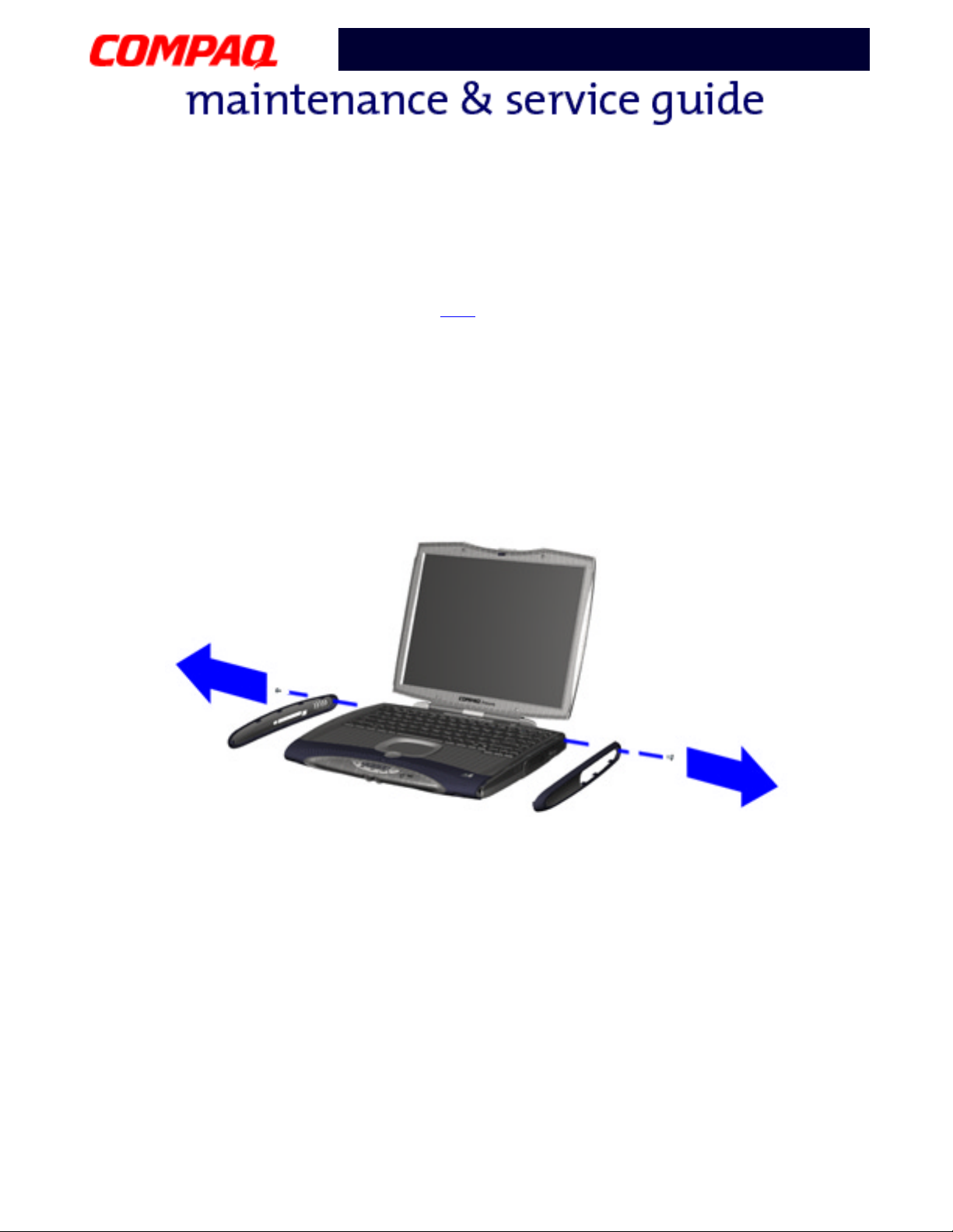
Cosmetic Side Covers
To remove the Cosmetic Side Covers, complete the following steps:
1. Prepare the Notebook for disassembly (pg 4
).
2. Remove one screw located on the side near the back of the unit with a Phillips screwdriver
from the cosmetic side cover, left or right.
3. Slide or shift the cosmetic side cover backward to remove it from the Notebook.
4. Repeat this procedure for the other cosmetic side cover.
Note: To determine left and right sides of the Notebook, as referenced in this guide, face
the front of the unit toward you. As referenced in this guide, your left will be the same as
the Notebook’s left side, and your right will be the same as the Notebook’s right side.
To replace the Cosmetic Side Covers, reverse the procedure.
P
RESARIO NOTEBOOK MAINTENANCE AND SERVICE GUIDE
1400 S
ERIES
R
EMOVAL SEQUENCE
7
Page 9
Presario 1400 Series
Model XL240, XL241, XL242, XL244, XL245, XL246, XL247, XL250, XL340,
XL341, XL342, XL343, XL344, XL345, XL346, XL350, XL352, XL355, and XL356
Speaker Port Covers
To remove the Speaker Port Covers, complete the following steps:
1. Prepare the Notebook for disassembly (pg 4
2. Remove the cosmetic side covers (pg 7
).
).
3. Remove the upper and lower Speaker Port Covers from chassis.
To replace the Speaker Port Covers, reverse these procedures.
8 R
EMOVAL SEQUENCE
P
RESARIO NOTEBOOK MAINTENANCE AND SERVICE GUIDE
1400 S
ERIES
Page 10
Presario 1400 Series
Model XL240, XL241, XL242, XL244, XL245, XL246, XL247, XL250, XL340,
XL341, XL342, XL343, XL344, XL345, XL346, XL350, XL352, XL355, and XL356
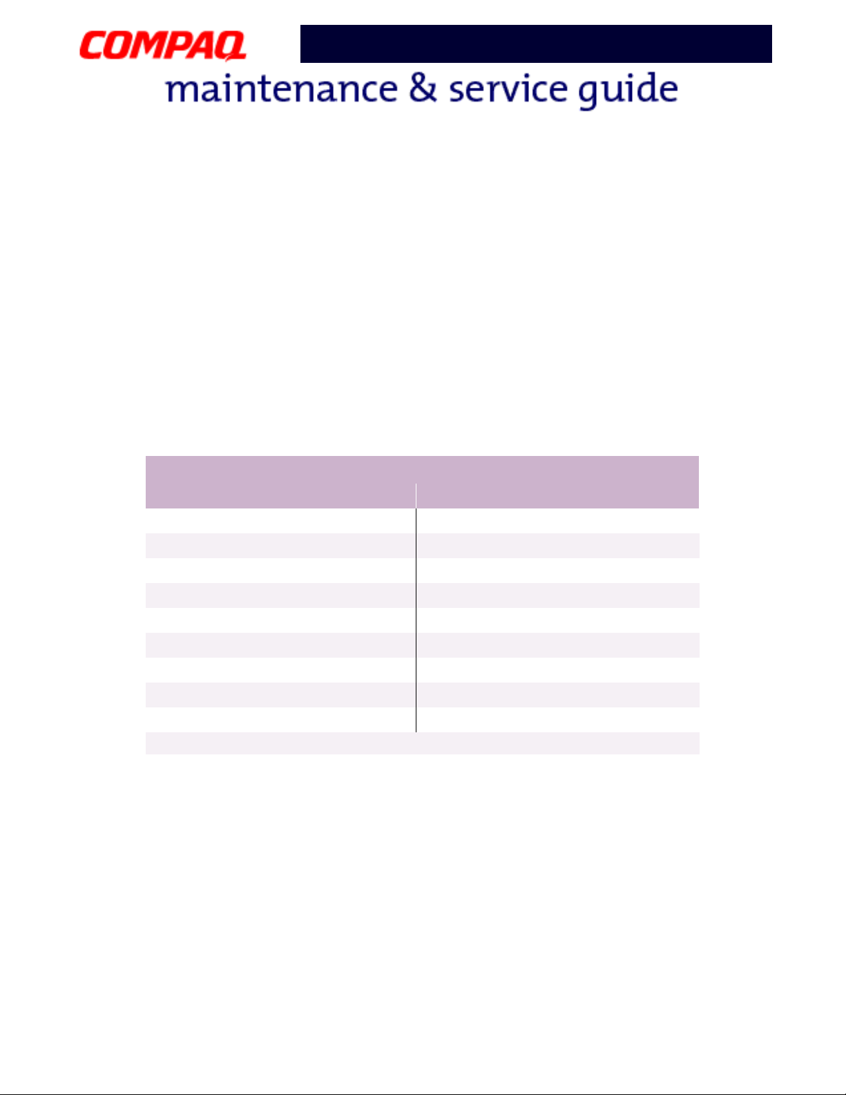
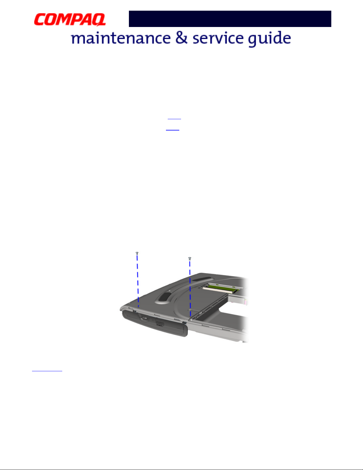
Modem/Memory Access Door
To remove the Modem/Memory Access Door, complete the following steps:
1. Prepare the Notebook for disassembly (pg 4
).
2. Turn the Notebook upside down.
3. Remove the one screw
Memory Access Door
1 with Phillips screwdriver from the Modem/
2.
4. Lift up and remove the Modem/Memory Access Door from the unit.
Note: The illustration may show extra components removed that are
not necessary for this step. Complete only the written steps that are
provided.
To replace the Modem/Memory Access Door, reverse these procedures.
P
RESARIO NOTEBOOK MAINTENANCE AND SERVICE GUIDE
1400 S
ERIES
R
EMOVAL SEQUENCE
9
Page 11
Presario 1400 Series
Model XL240, XL241, XL242, XL244, XL245, XL246, XL247, XL250, XL340,
XL341, XL342, XL343, XL344, XL345, XL346, XL350, XL352, XL355, and XL356
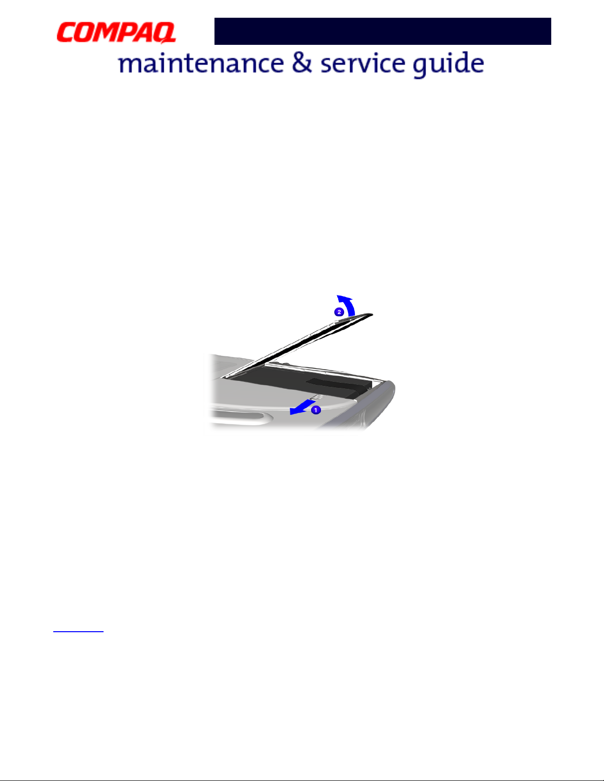
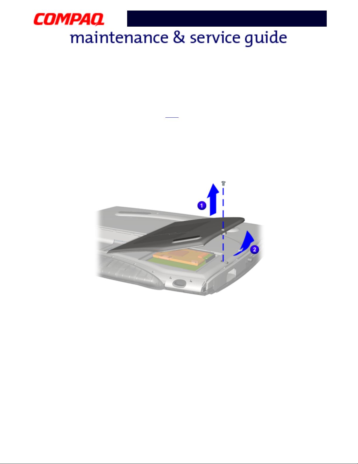
Modem or Network/Modem Combo Card
To remove the Modem, complete the following steps:
1. Prepare the Notebook for disassembly (pg 4
).
2. Turn the Notebook over.
3. Remove the Modem/Memory Access door from the unit (pg 9
4. Pull the tab
5. Lift and remove the card
1 on each side of the Modem or Network/Modem Card.
2 from the chassis.
).
To replace the Modem, reverse these procedures.
10 R
EMOVAL SEQUENCE
P
RESARIO NOTEBOOK MAINTENANCE AND SERVICE GUIDE
1400 S
ERIES
Page 12
Presario 1400 Series
Model XL240, XL241, XL242, XL244, XL245, XL246, XL247, XL250, XL340,
XL341, XL342, XL343, XL344, XL345, XL346, XL350, XL352, XL355, and XL356
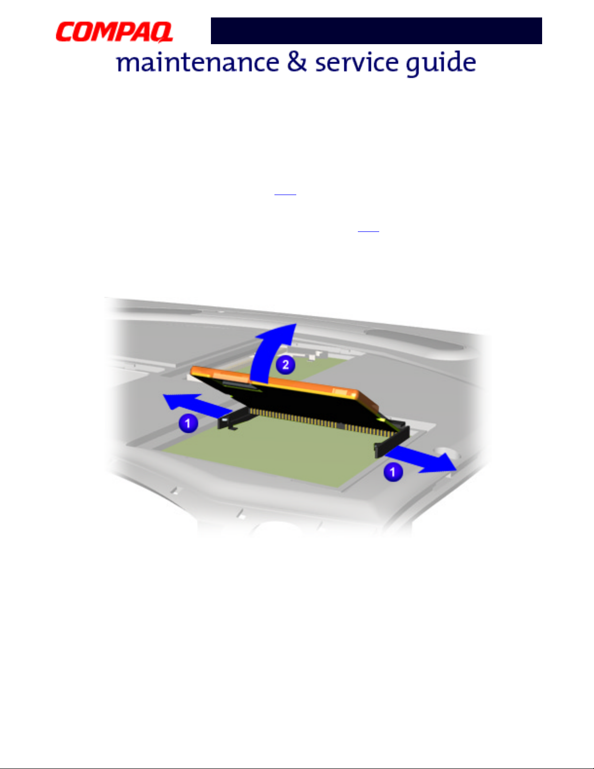
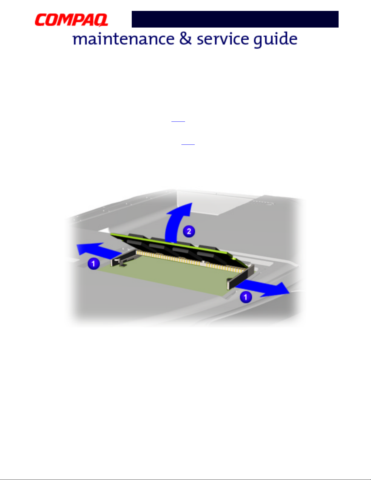
Extended Memory Card
To remove the Extended Memory Card, complete the following steps:
1. Prepare the Notebook for disassembly (pg 4
).
2. Turn the Notebook upside down.
3. Remove the Modem/Memory Access door (pg 9
4. Pull the tab
5. Lift and remove the Extended Memory Card
1 on each side of the Extended Memory Card.
2 from the connectors.
).
To replace the Extended Memory Card, reverse these procedures.
P
RESARIO NOTEBOOK MAINTENANCE AND SERVICE GUIDE
1400 S
ERIES
R
EMOVAL SEQUENCE
11
Page 13
Presario 1400 Series
Model XL240, XL241, XL242, XL244, XL245, XL246, XL247, XL250, XL340,
XL341, XL342, XL343, XL344, XL345, XL346, XL350, XL352, XL355, and XL356
DVD, CD-Rom, or CD-RW Drive
To remove the DVD, CD-Rom, or CD-RW Drive, complete the following steps:
1. Prepare the Notebook for disassembly (pg 4
2. Remove the right cosmetic side cover (pg 7
).
).
Note: It is not necessary to remove the left cosmetic side cover to remove the
DVD, CD-Rom, or CD-RW Drive.
3. Turn the Notebook upside down.
4. Remove two screws from underneath the unit on the left side.
Note: The illustration may show extra components removed that are
not necessary for this step. Complete only the written steps that are
provided.
Continued
12 R
EMOVAL SEQUENCE
P
RESARIO NOTEBOOK MAINTENANCE AND SERVICE GUIDE
1400 S
ERIES
Page 14
Presario 1400 Series
Model XL240, XL241, XL242, XL244, XL245, XL246, XL247, XL250, XL340,
XL341, XL342, XL343, XL344, XL345, XL346, XL350, XL352, XL355, and XL356
5. Turn the Notebook over.
6. Slide the DVD, CD-Rom, or CD-RW Drive out to remove.
Note: The illustration may show extra components removed that are
not necessary for this step. Complete only the written steps that are
provided.
To replace the DVD, CD-Rom, or CD-RW Drive, reverse these procedures.
P
RESARIO NOTEBOOK MAINTENANCE AND SERVICE GUIDE
1400 S
ERIES
R
EMOVAL SEQUENCE
13
Page 15

Presario 1400 Series
Model XL240, XL241, XL242, XL244, XL245, XL246, XL247, XL250, XL340,
XL341, XL342, XL343, XL344, XL345, XL346, XL350, XL352, XL355, and XL356
Hard Drive
To remove the Hard Drive, complete the following steps:
1. Prepare the Notebook for disassembly (pg 4
2. Remove the left cosmetic side cover (pg 7
).
).
Note: It is not necessary to remove the right cosmetic side cover to remove the Hard
Drive.
3. Turn the Notebook upside down.
4. Remove one screw from underneath the unit.
Continued
14 R
EMOVAL SEQUENCE
P
RESARIO NOTEBOOK MAINTENANCE AND SERVICE GUIDE
1400 S
ERIES
Page 16

Presario 1400 Series
Model XL240, XL241, XL242, XL244, XL245, XL246, XL247, XL250, XL340,
XL341, XL342, XL343, XL344, XL345, XL346, XL350, XL352, XL355, and XL356
5. Turn the unit over.
6. Slide the Hard Drive out and remove.
To replace the Hard Drive, reverse the procedure.
P
RESARIO NOTEBOOK MAINTENANCE AND SERVICE GUIDE
1400 S
ERIES
R
EMOVAL SEQUENCE
15
Page 17

Presario 1400 Series
Model XL240, XL241, XL242, XL244, XL245, XL246, XL247, XL250, XL340,
XL341, XL342, XL343, XL344, XL345, XL346, XL350, XL352, XL355, and XL356
The Service Removable Parts
Serial Number
When customers request information or order spare parts, be sure to ask them for their Notebook’s
serial number
1. It is located on the underside of the unit.
Before servicing the unit, refer to Preparing the Notebook for Disassembly (pg 4
WARNING: Before servicing the Notebook, disconnect AC power cords and
Å
external devices, and remove the battery pack and any PC Cards. Failure to
disconnect electrical devices may cause damage to the Notebook and loss of
human life.
).
16 R
EMOVAL SEQUENCE
P
RESARIO NOTEBOOK MAINTENANCE AND SERVICE GUIDE
1400 S
ERIES
Page 18

Presario 1400 Series
Model XL240, XL241, XL242, XL244, XL245, XL246, XL247, XL250, XL340,
XL341, XL342, XL343, XL344, XL345, XL346, XL350, XL352, XL355, and XL356
Electrostatic Discharge
A sudden discharge of static electricity from a finger or other conductor can destroy static-sensitive
devices or microcircuitry. Often the spark is neither felt nor heard, but damage occurs. An electronic
device that has been exposed to electrostatic discharge (ESD) may not seem to be affected and
work perfectly throughout a normal cycle. Although it may function normally for a period of time, it
may have been degraded in the internal layers, reducing its life expectancy.
Networks built into many integrated circuits provide some protection, but in many cases the
discharge contains enough power to alter device parameters or melt silicon junctions.
Generating Static
The table below shows activities that generate static electricity and their associated level of
electrostatic voltage.
Typical Electrostatic Voltages
Event Relative Humidity
10% 40% 55%
Walking across carpet 35,000 V 15,000 V 7,500 V
Walking across vinyl floor 12,000 V 5,000 V 3,000 V
Motions of bench worker 6,000 V 800 V 400 V
Removing DIPS from plastic tubes 2,000 V 700 V 400 V
Removing DIPS from vinyl trays 11,500 V 4,000 V 2,000 V
Removing DIPS from Styrofoam 14,500 V 5,000 V 3,500 V
Removing bubble pack from PCBs 26,000 V 20,000 V 7,000 V
Packing PCBs in foam-lined box 21,000 V 11,000 V 5,000 V
Note: 700 volts can degrade a product.
P
RESARIO NOTEBOOK MAINTENANCE AND SERVICE GUIDE
1400 S
ERIES
R
EMOVAL SEQUENCE
17
Page 19

Presario 1400 Series
Model XL240, XL241, XL242, XL244, XL245, XL246, XL247, XL250, XL340,
XL341, XL342, XL343, XL344, XL345, XL346, XL350, XL352, XL355, and XL356
Service Considerations
During the disassembly and assembly of the Notebook, please keep in mind the considerations listed
below.
Tool and Software Requirements
To service the Notebook, the following items are required:
•
Torx T-8 or T-9 screwdriver
•
5mm nut drivers (for screwlocks and standoffs)
•
Small standard screwdriver
•
Small Phillips screwdriver
•
Diagnostics software
Screws
The screws are not interchangeable. If an incorrect screw is applied during the reassembly process,
it can damage the unit. Compaq strongly recommends that you keep all screws with their respective
parts as they are removed during disassembly. Then replace the screws in their proper locations.
As each subassembly is removed from the Notebook, place it away from the work area to prevent
damage.
18 R
EMOVAL SEQUENCE
P
RESARIO NOTEBOOK MAINTENANCE AND SERVICE GUIDE
1400 S
ERIES
Page 20

Presario 1400 Series
Model XL240, XL241, XL242, XL244, XL245, XL246, XL247, XL250, XL340,
XL341, XL342, XL343, XL344, XL345, XL346, XL350, XL352, XL355, and XL356
Cables and Connectors
Most of the cables inside the Notebook are ribbon cables. Handle cables with extreme care to avoid
damage. During insertion or removal from the connector, apply only the amount of pressure
required to seat or unseat the cable, handling it by the connector whenever possible. In all cases,
avoid bending, twisting, or tearing the cables. Route cables in such a way that they cannot be
caught or snagged by parts being removed or replaced.
Cables
To avoid damage to the cable or the Notebook, the following precautions should be taken when
handling cables:
•
Always handle cables by their connectors.
•
Avoid bending, twisting, or pulling on the cables.
•
Apply minimum required force when seating or unseating the cables from their connectors.
•
Place the cables in such a manner that they cannot be caught or snagged by parts being
removed or replaced.
•
Handle flex cables with extreme care; they can tear easily.
CAUTION:
Ä
Ä
ÄÄ
the reassembly process. Improper cable placement can cause severe damage to
the Notebook.
When servicing Notebooks, place cables in their proper location during
Cable Illustrations
The following illustrations show the proper placement for each cable:
•
Zif Cable
•
Speaker Assembly Cable
•
Keyboard Ribbon Cable
•
NIC Cable
P
RESARIO NOTEBOOK MAINTENANCE AND SERVICE GUIDE
1400 S
ERIES
R
EMOVAL SEQUENCE
19
Page 21

Presario 1400 Series
Model XL240, XL241, XL242, XL244, XL245, XL246, XL247, XL250, XL340,
XL341, XL342, XL343, XL344, XL345, XL346, XL350, XL352, XL355, and XL356
Connectors and Plastic Parts
Plastic parts can be damaged by the use of excessive force during disassembly and reassembly.
Handle with care when disassembling and assembling plastic parts. As recommended in the
maintenance instructions, apply pressure only at the designated points.
ZIF Connectors
The Notebook uses zero insertion force (ZIF) connectors on the system board.
CAUTION:
Ä
Ä
ÄÄ
only the connector slide when removing or replacing a cable. Never pull or twist on
a cable while it is connected.
To remove a cable from a ZIF connector, lift both corners of the ZIF connector and slide
simultaneously with constant light pressure.
CAUTION:
Ä
Ä
ÄÄ
the reassembly process. Improper cable placement can cause severe damage to
the Notebook.
A ZIF connector and its attached cable can be easily damaged. Handle
When servicing a Notebook, place cables in their proper location during
To view other cables, click Cable Illustrations.
20 R
EMOVAL SEQUENCE
P
RESARIO NOTEBOOK MAINTENANCE AND SERVICE GUIDE
1400 S
ERIES
Page 22

Presario 1400 Series
Model XL240, XL241, XL242, XL244, XL245, XL246, XL247, XL250, XL340,
XL341, XL342, XL343, XL344, XL345, XL346, XL350, XL352, XL355, and XL356
Speaker Assembly Cable
The ribbon cable position for the speaker assembly is shown below.
CAUTION:
Ä
Ä
ÄÄ
the reassembly process. Improper cable placement can cause severe damage to
the Notebook.
To view other cables, click Cable Illustrations.
P
RESARIO NOTEBOOK MAINTENANCE AND SERVICE GUIDE
When servicing a Notebook, place cables in their proper location during
1400 S
ERIES
R
EMOVAL SEQUENCE
21
Page 23

Presario 1400 Series
Model XL240, XL241, XL242, XL244, XL245, XL246, XL247, XL250, XL340,
XL341, XL342, XL343, XL344, XL345, XL346, XL350, XL352, XL355, and XL356
Keyboard Ribbon Cable
The ribbon cable position for the keyboard is shown below.
CAUTION:
Ä
Ä
ÄÄ
the reassembly process. Improper cable placement can cause severe damage to
the Notebook.
To view other cables, click Cable Illustrations.
22 R
EMOVAL SEQUENCE
When servicing a Notebook, place cables in their proper location during
P
RESARIO NOTEBOOK MAINTENANCE AND SERVICE GUIDE
1400 S
ERIES
Page 24

Presario 1400 Series
Model XL240, XL241, XL242, XL244, XL245, XL246, XL247, XL250, XL340,
XL341, XL342, XL343, XL344, XL345, XL346, XL350, XL352, XL355, and XL356
Internet Button Board Cover
1. Prepare the Notebook for disassembly (pg 4).
2. Remove the cosmetic side covers (pg 7
).
3. Turn the Notebook upside down.
4. Remove the two screws from underneath the unit toward the rear.
Continued
P
RESARIO NOTEBOOK MAINTENANCE AND SERVICE GUIDE
1400 S
ERIES
R
EMOVAL SEQUENCE
23
Page 25

Presario 1400 Series
Model XL240, XL241, XL242, XL244, XL245, XL246, XL247, XL250, XL340,
XL341, XL342, XL343, XL344, XL345, XL346, XL350, XL352, XL355, and XL356
5. Carefully pry with the flat end of a screwdriver to lift the Internet Button Board Cover.
6. Disconnect the backlight and flex cables.
7. Remove the Internet Button Board Cover from the Notebook.
Note: The hinge covers and backlight switch are located on the Internet Button Board
Cover.
To replace the Internet Button Board Cover, reverse the procedure.
24 R
EMOVAL SEQUENCE
P
RESARIO NOTEBOOK MAINTENANCE AND SERVICE GUIDE
1400 S
ERIES
Page 26

Presario 1400 Series
Model XL240, XL241, XL242, XL244, XL245, XL246, XL247, XL250, XL340,
XL341, XL342, XL343, XL344, XL345, XL346, XL350, XL352, XL355, and XL356
Keyboard
To remove the keyboard, complete the following steps:
1. Prepare the Notebook for disassembly (pg 4
2. Remove the cosmetic side covers (pg 7
3. Remove the Internet Button Board Cover (pg 23
).
).
).
4. Lift the back of the keyboard and disconnect the flex cable from the ZIF Connector on the
system board.
5. Remove the keyboard from the unit.
Note: When replacing the keyboard, the Keyboard Ribbon Cable should fold behind the
ZIF Connectors rather than underneath the keyboard.
P
RESARIO NOTEBOOK MAINTENANCE AND SERVICE GUIDE
1400 S
ERIES
R
EMOVAL SEQUENCE
25
Page 27

Presario 1400 Series
Model XL240, XL241, XL242, XL244, XL245, XL246, XL247, XL250, XL340,
XL341, XL342, XL343, XL344, XL345, XL346, XL350, XL352, XL355, and XL356
PCA Button Board
To remove the PCA Button Board, complete the following steps:
1. Prepare the Notebook for disassembly (pg 4
2. Remove the cosmetic side covers (pg 7
3. Remove the Internet Button Board Cover (pg 23
4. Remove the keyboard (pg 25
).
).
).
).
5. Disconnect the backlight cable from the system board.
Note: Do not use excessive force when removing cables or boards.
Continued
26 R
EMOVAL SEQUENCE
P
RESARIO NOTEBOOK MAINTENANCE AND SERVICE GUIDE
1400 S
ERIES
Page 28

Presario 1400 Series
Model XL240, XL241, XL242, XL244, XL245, XL246, XL247, XL250, XL340,
XL341, XL342, XL343, XL344, XL345, XL346, XL350, XL352, XL355, and XL356
6. Remove two screws 1 on the PCA Button Board.
7. Pry with the flat end of a screwdriver and lift the PCA Button Board. The data cable that is
attached to the PCA Button Board is still connected to the system board.
8. Disconnect the data cable
3 on the bottom side of the PCA Button
Board.
9. Remove the PCA Button Board
2 from the chassis.
Note: The EMI Shields are lightweight pieces of metal. Be sure not to lose these shields
when removing the PCA Button Board or Display Panel Assembly.
To replace the PCA Button Board, reverse these procedures.
P
RESARIO NOTEBOOK MAINTENANCE AND SERVICE GUIDE
1400 S
ERIES
R
EMOVAL SEQUENCE
27
Page 29

Presario 1400 Series
Model XL240, XL241, XL242, XL244, XL245, XL246, XL247, XL250, XL340,
XL341, XL342, XL343, XL344, XL345, XL346, XL350, XL352, XL355, and XL356
Display Panel Assembly
To remove the display panel assembly, complete the following steps:
1. Prepare the Notebook for disassembly (pg 4
2. Remove the cosmetic side covers (pg 7
).
).
3. Remove the Internet Button Board cover (pg 23
4. Remove the keyboard (pg 25
5. Remove the PCA Button Board (pg 26
6. Remove the four screws
).
).
1 from the hinges securing the Display Panel Assembly. Be sure to
keep the EMI shields with the Display Panel Assembly.
7. Lift and remove the Display Panel
2 Assembly from the chassis.
).
Note: The EMI Shields are lightweight pieces of metal. Be sure not to lose the shields
when removing the PCA Button Board or Display Panel Assembly.
To replace the Display Panel Assembly, reverse these procedures.
28 R
EMOVAL SEQUENCE
P
RESARIO NOTEBOOK MAINTENANCE AND SERVICE GUIDE
1400 S
ERIES
Page 30

Presario 1400 Series
Model XL240, XL241, XL242, XL244, XL245, XL246, XL247, XL250, XL340,
XL341, XL342, XL343, XL344, XL345, XL346, XL350, XL352, XL355, and XL356
MP3 Zone Cover
To Remove the MP3 Zone Cover, complete the following steps:
1. Prepare the Notebook for disassembly (pg 4
2. Remove the cosmetic side covers (pg 7
3. Remove the speaker port covers (pg 8
4. Remove the four screws
5. Pull the MP3 Zone Cover
1 from the MP3 Zone Cover.
2 forward and remove it from the chassis.
).
).
).
To replace the MP3 Zone Cover, reverse these procedures.
P
RESARIO NOTEBOOK MAINTENANCE AND SERVICE GUIDE
1400 S
ERIES
R
EMOVAL SEQUENCE
29
Page 31

Presario 1400 Series
Model XL240, XL241, XL242, XL244, XL245, XL246, XL247, XL250, XL340,
XL341, XL342, XL343, XL344, XL345, XL346, XL350, XL352, XL355, and XL356
Heatspreader with Fan Assembly
To remove the Heatspreader with Fan Assembly, complete the following steps:
1. Prepare the Notebook for disassembly (pg 4
2. Remove the cosmetic side covers (pg 7
).
).
3. Remove the Internet Button Board cover (pg 23
4. Remove the keyboard (pg 25
5. Remove five screws
1 with a T-9 Torx driver.
6. Remove the heatspreader
7. Disconnect the fan cable
).
2 with fan assembly.
3 from the system board.
).
To replace the heatspreader, reverse these procedures.
Note: When replacing the Heatspreader, be sure that the Heatspreader is lying on top of the
CPU Upper Cover with Palmrest and Touch Pad. The CD/DVD will not operate if the
Heatspreader is installed incorrectly.
30 R
EMOVAL SEQUENCE
P
RESARIO NOTEBOOK MAINTENANCE AND SERVICE GUIDE
1400 S
ERIES
Page 32

Presario 1400 Series
Model XL240, XL241, XL242, XL244, XL245, XL246, XL247, XL250, XL340,
XL341, XL342, XL343, XL344, XL345, XL346, XL350, XL352, XL355, and XL356
Fan Assembly
To remove the Fan Assembly, complete the following steps:
1. Prepare the Notebook for disassembly (pg 4
2. Remove the cosmetic side covers (pg 7
3. Remove the Internet Button Board cover (pg 23
4. Remove the keyboard (pg 25
).
).
).
).
5. Remove the Heatspreader with Fan Assembly (pg 30
6. Remove two screws
7. Lift and remove the Fan Assembly
1 with a Phillips screwdriver.
2 from the Heatspreader.
).
To replace the Fan Assembly, reverse the procedure.
P
RESARIO NOTEBOOK MAINTENANCE AND SERVICE GUIDE
1400 S
ERIES
R
EMOVAL SEQUENCE
31
Page 33

Presario 1400 Series
Model XL240, XL241, XL242, XL244, XL245, XL246, XL247, XL250, XL340,
XL341, XL342, XL343, XL344, XL345, XL346, XL350, XL352, XL355, and XL356
Palmrest Cover with TouchPad (Upper CPU)
To remove the Palmrest Cover with TouchPad (Upper CPU), complete the following steps:
1. Prepare the Notebook for disassembly (pg 4
2. Remove the cosmetic side covers (pg 7
3. Remove the speaker port covers (pg 8
).
).
).
4. Remove the Power-on and Internet Button Board Cover (pg 23
5. Remove the keyboard (pg 25
6. Remove the PCA Button Board (pg 26
7. Remove the display panel assembly (pg 28
8. Remove the Modem/Memory Access Door (pg 9
9. Remove the MP3 Zone Cover (pg 29
10. Remove the Heatspreader (pg 30
).
).
).
).
).
).
Continued
).
32 R
EMOVAL SEQUENCE
P
RESARIO NOTEBOOK MAINTENANCE AND SERVICE GUIDE
1400 S
ERIES
Page 34

Presario 1400 Series
Model XL240, XL241, XL242, XL244, XL245, XL246, XL247, XL250, XL340,
XL341, XL342, XL343, XL344, XL345, XL346, XL350, XL352, XL355, and XL356
11. Remove seven screws 1 and one standoff from the Upper CPU Cover
with Palmrest and TouchPad.
12. Remove the TouchPad data cable with a flat-blade screwdriver.
13. Lift the Upper CPU Cover with Palmrest and TouchPad
it from the chassis.
2 upward and remove
Note: Illustrations may show a fewer number of screws removed. It is necessary to
remove only the parts listed in the written procedure.
To replace the Upper CPU Cover with Palmrest and TouchPad, reverse these procedures.
P
RESARIO NOTEBOOK MAINTENANCE AND SERVICE GUIDE
1400 S
ERIES
R
EMOVAL SEQUENCE
33
Page 35

Presario 1400 Series
Model XL240, XL241, XL242, XL244, XL245, XL246, XL247, XL250, XL340,
XL341, XL342, XL343, XL344, XL345, XL346, XL350, XL352, XL355, and XL356
Modem/Modem-NIC Combo Cable
To remove the NIC (Network Interface Card) cable, complete the following steps:
1. Prepare the Notebook for disassembly (pg 4
2. Remove the cosmetic side covers (pg 7
3. Remove the speaker port covers (pg 8
4. Remove the Modem/Memory Access Door (pg 9
5. Remove the Internet Button Board cover (pg 23
6. Remove the keyboard (pg 25
7. Remove the PCA Button Board (pg 26
).
).
8. Remove the display panel assembly (pg 28
9. Remove the MP3 zone cover (pg 29
10. Remove the heatspreader (pg 30
).
).
).
).
).
).
).
).
11. Remove the Palmrest Cover with TouchPad, Upper CPU, (pg 32
Continued
).
34 R
EMOVAL SEQUENCE
P
RESARIO NOTEBOOK MAINTENANCE AND SERVICE GUIDE
1400 S
ERIES
Page 36

Presario 1400 Series
Model XL240, XL241, XL242, XL244, XL245, XL246, XL247, XL250, XL340,
XL341, XL342, XL343, XL344, XL345, XL346, XL350, XL352, XL355, and XL356
12. Disconnect and lift off the large end 1 of the Modem/NIC cable connector
located near the hard drive.
13. Disconnect and lift off the small end
2 of the Modem/NIC cable connector located
near the rear of the unit.
14. Remove one standoff with a 5mm nut driver.
15. Remove NIC cable from chassis.
To replace the NIC Cable, reverse the procedure.
P
RESARIO NOTEBOOK MAINTENANCE AND SERVICE GUIDE
1400 S
ERIES
R
EMOVAL SEQUENCE
35
Page 37

Presario 1400 Series
Model XL240, XL241, XL242, XL244, XL245, XL246, XL247, XL250, XL340,
XL341, XL342, XL343, XL344, XL345, XL346, XL350, XL352, XL355, and XL356
MP3 Audio Board
To remove the MP3 Audio Board, complete the following steps:
1. Prepare the Notebook for disassembly (pg 4
2. Remove the cosmetic side covers (pg 7
3. Remove the speaker port covers (pg 8
4. Remove the Modem/Memory Access Door (pg 9
5. Remove the Internet Button Board Cover (pg 23
6. Remove the keyboard (pg 25
7. Remove the PCA Button Board (pg 26
).
).
8. Remove the display panel assembly (pg 28
9. Remove the MP3 Zone Cover (pg 29
10. Remove the Heatspreader (pg 30
).
).
).
).
).
).
).
).
11. Remove the Palmrest Cover with TouchPad, Upper CPU, (pg 32
Continued
).
36 R
EMOVAL SEQUENCE
P
RESARIO NOTEBOOK MAINTENANCE AND SERVICE GUIDE
1400 S
ERIES
Page 38

Presario 1400 Series
Model XL240, XL241, XL242, XL244, XL245, XL246, XL247, XL250, XL340,
XL341, XL342, XL343, XL344, XL345, XL346, XL350, XL352, XL355, and XL356
12. Remove one screw 1 from the system board.
13. Lift and remove the MP3 Audio Board
2 from the system board.
14. Disconnect the speaker cable from the system board.
To replace the MP3 Audio Board, reverse the procedure.
P
RESARIO NOTEBOOK MAINTENANCE AND SERVICE GUIDE
1400 S
ERIES
R
EMOVAL SEQUENCE
37
Page 39

Presario 1400 Series
Model XL240, XL241, XL242, XL244, XL245, XL246, XL247, XL250, XL340,
XL341, XL342, XL343, XL344, XL345, XL346, XL350, XL352, XL355, and XL356
Speaker Assembly
To remove the Speaker Assembly, complete the following steps:
1. Prepare the Notebook for disassembly (pg 4
2. Remove the cosmetic side covers (pg 7
3. Remove the speaker port covers (pg 8
4. Remove the Modem/Memory Access Door (pg 9
5. Remove the Internet Button Board cover (pg 23
6. Remove the keyboard (pg 25
7. Remove the PCA Button Board (pg 26
).
).
8. Remove the display panel assembly (pg 28
9. Remove the MP3 Zone Cover (pg 29
10. Remove the Heatspreader (pg 30
).
).
).
).
).
).
).
).
11. Remove the Palmrest Cover with TouchPad, Upper CPU, (pg 32
12. Remove the MP3 audio board (pg 36
).
Continued
).
38 R
EMOVAL SEQUENCE
P
RESARIO NOTEBOOK MAINTENANCE AND SERVICE GUIDE
1400 S
ERIES
Page 40

Presario 1400 Series
Model XL240, XL241, XL242, XL244, XL245, XL246, XL247, XL250, XL340,
XL341, XL342, XL343, XL344, XL345, XL346, XL350, XL352, XL355, and XL356
13. Lift and remove the Speaker Assembly from the chassis.
To replace the Speaker Assembly, reverse the procedure.
P
RESARIO NOTEBOOK MAINTENANCE AND SERVICE GUIDE
1400 S
ERIES
R
EMOVAL SEQUENCE
39
Page 41

Presario 1400 Series
Model XL240, XL241, XL242, XL244, XL245, XL246, XL247, XL250, XL340,
XL341, XL342, XL343, XL344, XL345, XL346, XL350, XL352, XL355, and XL356
System Board
To remove the system board, complete the following steps:
1. Prepare the Notebook for disassembly (pg 4
2. Remove the cosmetic side covers (pg 7
3. Remove the speaker port covers (pg 8
4. Remove the modem/memory access door (pg 9
5. Remove the CD drive (pg 12
6. Remove the hard drive (pg 14
).
).
7. Remove the Internet Button Board cover (pg 23
8. Remove the keyboard (pg 25
9. Remove the PCA Button Board (pg 26
).
).
10. Remove the display panel assembly (pg 28
11. Remove the MP3 Zone Cover (pg 29
12. Remove the heatspreader (pg 30
).
).
).
).
).
).
).
).
13. Remove the Palmrest Cover with TouchPad, Upper CPU, (pg 32
14. Remove the NIC cable (pg 34
15. Remove the MP3 audio board (pg 36
16. Remove the Speaker Assembly (pg 38
).
).
).
).
Continued
40 R
EMOVAL SEQUENCE
P
RESARIO NOTEBOOK MAINTENANCE AND SERVICE GUIDE
1400 S
ERIES
Page 42

Presario 1400 Series
Model XL240, XL241, XL242, XL244, XL245, XL246, XL247, XL250, XL340,
XL341, XL342, XL343, XL344, XL345, XL346, XL350, XL352, XL355, and XL356
17. Remove four screws 1 from two Hard Drive Rails.
18. Remove both Hard Drive Rails
2 from the system board.
Continued
P
RESARIO NOTEBOOK MAINTENANCE AND SERVICE GUIDE
1400 S
ERIES
R
EMOVAL SEQUENCE
41
Page 43

Presario 1400 Series
Model XL240, XL241, XL242, XL244, XL245, XL246, XL247, XL250, XL340,
XL341, XL342, XL343, XL344, XL345, XL346, XL350, XL352, XL355, and XL356
19. Remove six 5mm standoffs 1 from system board.
20. Lift system board
2 from chassis.
Note: Illustrations may show a fewer number of standoffs removed. It is necessary to
remove only the parts listed in the written procedure.
To replace the system board, reverse the procedure.
42 R
EMOVAL SEQUENCE
P
RESARIO NOTEBOOK MAINTENANCE AND SERVICE GUIDE
1400 S
ERIES
Page 44

Presario 1400 Series
Model XL240, XL241, XL242, XL244, XL245, XL246, XL247, XL250, XL340,
XL341, XL342, XL343, XL344, XL345, XL346, XL350, XL352, XL355, and XL356
Processor
To remove the processor, complete the following steps:
1. Prepare the Notebook for disassembly (pg 4
2. Remove the cosmetic side covers (pg 7
3. Remove the Internet Button Board cover (pg 23
4. Remove the PCA Button Board (pg 26
5. Remove the keyboard (pg 25
).
6. Remove MP3 Zone Cover (pg 29
7. Remove the heatspreader (pg 30
).
).
).
).
).
).
8. Remove the Palmrest Cover with TouchPad, Upper CPU, (pg 32
Continued
).
P
RESARIO NOTEBOOK MAINTENANCE AND SERVICE GUIDE
1400 S
ERIES
R
EMOVAL SEQUENCE
43
Page 45

Presario 1400 Series
Model XL240, XL241, XL242, XL244, XL245, XL246, XL247, XL250, XL340,
XL341, XL342, XL343, XL344, XL345, XL346, XL350, XL352, XL355, and XL356
9. Shift with the flat end of screwdriver to the side in the slot 1 that reads “OPEN” to
unlock the processor.
10. Lift the processor
Note: The bottom of the processor contains socket pins that can be easily damaged if
not properly removed or installed.
WARNING: The processor may become very hot after the unit has been
Å
operating. Allow the processor time to cool before handling it.
2 from the chassis.
To replace the processor, refer to Replacing the Processor.
44 R
EMOVAL SEQUENCE
P
RESARIO NOTEBOOK MAINTENANCE AND SERVICE GUIDE
1400 S
ERIES
Page 46

Presario 1400 Series
Model XL240, XL241, XL242, XL244, XL245, XL246, XL247, XL250, XL340,
XL341, XL342, XL343, XL344, XL345, XL346, XL350, XL352, XL355, and XL356
Replacing the Processor
To replace the processor, complete the following procedure:
1. Place the processor
triangle
2. Shift with the flat end of a screwdriver, to the side in the slot
the processor.
Note: The bottom of the processor contains socket pins that can be easily damaged if
not properly removed or installed.
Å
3.
WARNING: The processor may become very hot after the unit has been
operating. Allow the processor time to cool before handling it.
2 on the connectors correctly aligning the gold triangle with the silver
1 that reads “CLOSED” to lock
P
RESARIO NOTEBOOK MAINTENANCE AND SERVICE GUIDE
1400 S
ERIES
R
EMOVAL SEQUENCE
45
 Loading...