

Page 1

HP ProBook 5220m Notebook PC
Maintenance and Service Guide
SUMMARY
This guide is a troubleshooting reference used for maintaining and servicing the computer. It provides
comprehensive information on identifying computer features, components, and spare parts;
troubleshooting computer problems; and performing computer disassembly procedures.
Page 2

© Copyright 2010 Hewlett-Packard
Development Company, L.P.
Bluetooth is a trademark owned by its
proprietor and used by Hewlett-Packard
Company under license. Intel, Arrandale,
and Celeron are trademarks of Intel
Corporation in the United States and other
countries. Microsoft, Windows, and Windows
Vista are U.S. registered trademarks of
Microsoft Corporation. SD Logo is a
trademark of its proprietor.
The information contained herein is subject
to change without notice. The only
warranties for HP products and services are
set forth in the express warranty statements
accompanying such products and services.
Nothing herein should be construed as
constituting an additional warranty. HP shall
not be liable for technical or editorial errors
or omissions contained herein.
First Edition: May 2010
Document Part Number: 600137-001
Page 3

Safety warning notice
WARNING! To reduce the possibility of heat-related injuries or of overheating the computer, do not
place the computer directly on your lap or obstruct the computer air vents. Use the computer only on a
hard, flat surface. Do not allow another hard surface, such as an adjoining optional printer, or a soft
surface, such as pillows or rugs or clothing, to block airflow. Also, do not allow the AC adapter to contact
the skin or a soft surface, such as pillows or rugs or clothing, during operation. The computer and the
AC adapter comply with the user-accessible surface temperature limits defined by the International
Standard for Safety of Information Technology Equipment (IEC 60950).
iii
Page 4

iv Safety warning notice
Page 5

Table of contents
1 Product description ........................................................................................................................................ 1
2 External component identification ................................................................................................................ 7
Identifying hardware ............................................................................................................................. 7
Top components ................................................................................................................................... 8
TouchPad ............................................................................................................................ 8
Lights ................................................................................................................................... 9
Power button and fingerprint reader ................................................................................. 10
Keys ................................................................................................................................... 11
Front components .............................................................................................................................. 12
Right-side components ....................................................................................................................... 13
Left-side components ......................................................................................................................... 15
Bottom components ........................................................................................................................... 16
Display components .......................................................................................................................... 17
Wireless antennas .............................................................................................................................. 18
Additional hardware components ....................................................................................................... 19
3 Illustrated parts catalog ............................................................................................................................... 20
Serial number label location ............................................................................................................... 20
Computer major components ............................................................................................................. 21
Display assembly components ........................................................................................................... 25
Plastics Kit .......................................................................................................................................... 26
Cable Kit ............................................................................................................................................. 27
Mass storage devices ......................................................................................................................... 28
Miscellaneous parts ............................................................................................................................ 29
Sequential part number listing ............................................................................................................ 30
4 Removal and replacement procedures ....................................................................................................... 33
Preliminary replacement requirements ............................................................................................... 33
Tools required .................................................................................................................... 33
Service considerations ....................................................................................................... 33
Plastic parts ....................................................................................................... 33
Cables and connectors ..................................................................................... 34
v
Page 6

Drive handling ................................................................................................... 34
Grounding guidelines ......................................................................................................... 35
Electrostatic discharge damage ........................................................................ 35
Packaging and transporting guidelines ............................................. 36
Workstation guidelines ..................................................................... 36
Equipment guidelines ....................................................................... 37
Component replacement procedures ................................................................................................. 38
Service tag ......................................................................................................................... 38
Computer feet .................................................................................................................... 39
Battery ............................................................................................................................... 40
SIM .................................................................................................................................... 42
WLAN module .................................................................................................................... 42
WWAN module .................................................................................................................. 45
Memory module ................................................................................................................. 47
Hard drive .......................................................................................................................... 48
Switch cover ...................................................................................................................... 51
Keyboard ........................................................................................................................... 53
Top cover ........................................................................................................................... 56
Display assembly ............................................................................................................... 59
Modem module .................................................................................................................. 65
Bluetooth module ............................................................................................................... 67
Audio board ...................................................................................................................... 68
RTC battery ....................................................................................................................... 70
System board ..................................................................................................................... 71
Fan and heat sink .............................................................................................................. 75
Speakers ............................................................................................................................ 78
Security cable slot bracket ................................................................................................. 79
Power connector cable ...................................................................................................... 80
Modem module cable ........................................................................................................ 81
5 Computer Setup ............................................................................................................................................ 83
Computer Setup in Windows 7 ........................................................................................................... 83
Starting Computer Setup ................................................................................................... 83
Using Computer Setup ...................................................................................................... 83
Navigating and selecting in Computer Setup .................................................... 83
Restoring factory settings in Computer Setup ................................................... 84
Computer Setup menus ..................................................................................................... 84
File menu .......................................................................................................... 85
Security menu ................................................................................................... 85
System Configuration menu .............................................................................. 86
Computer Setup in Windows Vista and Windows XP ........................................................................ 91
Starting Computer Setup ................................................................................................... 91
Using Computer Setup ...................................................................................................... 91
vi
Page 7

Navigating and selecting in Computer Setup .................................................... 91
Restoring factory settings in Computer Setup ................................................... 92
Computer Setup menus ..................................................................................................... 93
File menu .......................................................................................................... 93
Security menu ................................................................................................... 94
System Configuration menu .............................................................................. 94
Computer Setup in Linux .................................................................................................................... 99
Starting Computer Setup ................................................................................................... 99
Using Computer Setup ...................................................................................................... 99
Navigating and selecting in Computer Setup .................................................... 99
Restoring factory settings in Computer Setup ................................................. 100
Computer Setup menus ................................................................................................... 100
File menu ........................................................................................................ 100
Security menu ................................................................................................. 100
Diagnostics menu ............................................................................................ 101
System Configuration menu ............................................................................ 102
6 Specifications .............................................................................................................................................. 104
Computer specifications ................................................................................................................... 104
30.7-cm (12.1-in) WXGA AntiGlare display specifications ............................................................... 105
30.7-cm (12.1-in) WXGA BrightView display specifications ............................................................. 106
Hard drive specifications .................................................................................................................. 107
7 Backup and recovery .................................................................................................................................. 108
Windows 7 backup and recovery ..................................................................................................... 108
Backing up your information ............................................................................................ 108
Performing a recovery ..................................................................................................... 109
Using the Windows recovery tools .................................................................. 110
Using f11 ......................................................................................................... 110
Using a Windows 7 operating system DVD (purchased separately) ............... 111
Windows Vista backup and recovery ............................................................................................... 112
Backing up your information ............................................................................................ 112
Performing a recovery ..................................................................................................... 113
Using the Windows recovery tools .................................................................. 113
Using f11 recovery tools .................................................................................. 114
Using a Windows Vista operating system DVD (purchased separately) ........ 115
Windows XP backup and recovery ................................................................................................... 116
Backing up your information ........................................................................................... 116
Performing a recovery ..................................................................................................... 117
Recovering your information ........................................................................... 117
Recovering the operating system and programs ............................................ 117
Linux backup and recovery .............................................................................................................. 118
vii
Page 8

8 Connector pin assignments ....................................................................................................................... 119
Audio-in (microphone) ...................................................................................................................... 119
Audio-out (headphone) ..................................................................................................................... 120
External monitor ............................................................................................................................... 121
HDMI ................................................................................................................................................ 122
RJ-11 (modem) ................................................................................................................................ 123
RJ-45 (network) ................................................................................................................................ 124
Universal Serial Bus ......................................................................................................................... 125
eSATA/USB ...................................................................................................................................... 126
9 Power cord set requirements .................................................................................................................... 127
Requirements for all countries and regions ...................................................................................... 127
Requirements for specific countries and regions ............................................................................. 128
10 Recycling ................................................................................................................................................... 129
Battery .............................................................................................................................................. 129
Display .............................................................................................................................................. 129
Index ................................................................................................................................................................. 135
viii
Page 9

1 Product description
Category Description
Product Name HP ProBook 5220m Notebook PC
Processors Intel® Celeron®
Intel® Arrandale™
Chipset Intel HM57 Express
Graphics Intel HD Graphics
Panels All display panel assemblies support privacy filter
LED backlight
Intel Celeron U3400 1.06-GHz
●
Intel Arrandale i3-350M, 2.26-GHz, 3-MB L3 cache, 4 threads (35 W)
●
Intel Arrandale i5-450M, 2.4-GHz (Turbo up to 2.66 GHz), 3-MB L3 Cache, 4
●
threads (35W)
Intel Arrandale i5-520M, 2.4-GHz (Turbo up to 2.93 GHz), 3-MB L3 cache, 4
●
threads
Intel Arrandale i5-540M, 2.53-GHz (Turbo up to 3.06 GHz), 3-MB L3 cache, 4
●
threads
Universal Memory Architecture (UMA) graphics subsystem integrated with shared
video memory (dynamically allocated)
30.734-cm (12.1-in) AntiGlare (1280x800)
●
30.734-cm (12.1-in) AntiGlare (1280x800) with webcam
●
30.734-cm (12.1-in) AntiGlare (1280x800) with webcam for use with WWAN
●
Memory 2 customer-accessible/upgradable SODIMM memory module slots
Supports dual-channel memory
Supports up to 8 GB of system memory
DDR3 PC3-10600 SDRAM (1333 MHz)
30.734-cm (12.1-in) BrightView (1280x800)
●
30.734-cm (12.1-in) BrightView (1280x800) with webcam
●
1
Page 10

Category Description
Supports the following configurations:
8192-MB total system memory (4096-MB × 2, dual-channel)
●
4096-MB total system memory (4096-MB × 1)
●
4096-MB total system memory (2048-MB × 2, dual-channel)
●
3072-MB total system memory (2048-MB + 1024-MB, dual-channel)
●
2048-MB total system memory (2048-MB × 1)
●
2048-MB total system memory (1024-MB × 2, dual-channel)
●
1024-MB total system memory (1024-MB × 1)
●
Hard drives Supports 9.5-mm, 6.35-cm (2.5-in) hard drives
Customer-accessible
Serial ATA (SATA)
Supports the following hard drives:
640-GB, 7200-rpm
●
500-GB, 7200-rpm
●
320-GB, 7200-rpm
●
250-GB, 7200-rpm
●
Supports the following solid-state drive:
80-GB
●
HP 3D DriveGuard (not available on Linux)
Audio/Visual HD audio - IDT 92HD80
Integrated microphone
Two stereo speakers
Integrated 2.0-megapixel webcam (fixed focus)
Modem High-speed 56k modem
Modem cable not included
Supports no-modem option
Ethernet 10/100/1000 Ethernet network interface card (NIC)
S3/S4/S5 wake on LAN (AC only mode)
Wireless Integrated WLAN options by way of wireless module:
Support for the following WLAN formats:
Intel Wi-Fi Link 1000 802.11b/g/n
●
2 Chapter 1 Product description
Intel WiFi Link 6200 802.11 a/b/g/n
●
Broadcom 4322 802.11a/b/g/n Wi-Fi Adapter
●
Broadcom 4313 802.11b/g/n 1x1 WiFi Adapter
●
Page 11

Category Description
2 WLAN antennas built into display assembly
Support for no-WLAN option
Integrated personal area network (PAN) options by way of Bluetooth® module:
Support for no-WPAN option
Broadcom Bluetooth 2.1 + Enhanced Data Rate (EDR)
Integrated WWAN options by way of WWAN module:
WWAN module Universal Notebook Data Platform (UNDP) with 2 antennas
Subscriber identity module (SIM) security (customer-accessible in battery bay)
External media cards Media Card Reader supporting Memory Stick (MS), Memory Stick Pro (MSP),
Ports Audio-in/Audio-out (stereo microphone/headphone)
RJ-11 (modem)
RJ-45 (Ethernet, includes link and activity lights)
USB 2.0 (3)
Combo eSATA/USB 2.0 (1)
HDMI
VGA (Dsub 15-pin) supporting 1600×1200 external resolution at 75 GHz (hot plug/
Multi-pin AC power
Keyboard and pointing devices Keyboard with TouchPad
TouchPad with 2 TouchPad buttons and vertical scrolling (taps enabled as default)
Power requirements 65-W AC adapter with localized cable plug support (3-wire plug with ground pin)
4-cell, 41-Wh 2.8-Ah Li-ion battery
6-cell, 62-Wh 2.8-Ah Li-ion battery
Security Supports Kensington security lock
Secure Digital (SD) Memory Card, Secure Digital High Capacity (SDHC) Memory
Card, MultiMediaCard (MMC), and xD-Picture Card formats
unplug with auto-detect)
Intel AT support
Integrated fingerprint reader
3
Page 12

Category Description
Operating systems Preinstalled:
Windows Vista® Home Basic (Japan only)
●
Windows Vista Business 32-bit (Japan only)
●
Windows® 7 Home Premium 32-bit (Japan only)
●
Windows 7 Home Premium 64-bit (Japan only)
●
Windows 7 Professional 32-bit (Japan only)
●
Windows 7 Professional 64-bit (Japan only)
●
Genuine Windows XP Professional available through downgrade rights from
●
Windows 7 (Japan only)
FreeDos
●
SuSE Linux (SLED11)
●
Red Flag Linux (People's Republic of China only)
●
4 Chapter 1 Product description
Page 13

Category Description
Microsoft Office preinstalled:
Windows Vista Home Basic 32-bit with Office Ready 2007 (excludes Japan)
●
Windows Vista Business 32-bit with Office Ready 2007 (excludes Japan)
●
Windows Vista Business 32-bit with Office Personal (Japan only)
●
Windows Vista Business 32-bit with Office Personal with PowerPoint (Japan
●
only)
Windows 7 Home Basic 32-bit with Office Ready 2007 (selected localizations
●
only)
Windows 7 Home Premium 32-bit with Office Ready 2007 (excludes Japan)
●
Windows 7 Home Premium 32-bit with Office Personal (Japan only)
●
Windows 7 Home Premium 32-bit with Office Personal with PowerPoint (Japan
●
only)
Windows 7 Home Pemium 64-bit with Office Ready 2007 (excludes Japan)
●
Windows 7 Home Premium 64-bit with Office Personal (Japan only)
●
Windows 7 Home Premium 64-bit with Office Personal with PowerPoint (Japan
●
only)
Windows 7 Professional 32-bit with Office Ready 2007 (excludes Japan)
●
Windows 7 Professional 32-bit with Office Personal (Japan only)
●
Windows 7 Professional 32-bit with Office Personal with PowerPoint (Japan
●
only)
Windows 7 Professional 64-bit with Office Ready 2007 (excludes Japan)
●
Windows 7 Professional 64-bit with Office Personal (Japan only)
●
Windows 7 Professional 64-bit with Office Personal with PowerPoint (Japan
●
only)
Genuine Windows XP Professional 32-bit available through downgrade rights
●
from Windows 7 Professional 32-bit with Office Ready 2007 (excludes Japan)
Genuine Windows XP Professional 32-bit available through downgrade rights
●
from Windows 7 Professional 32-bit with Office Personal (Japan only)
Genuine Windows XP Professional 32-bit available through downgrade rights
●
from Windows 7 Professional 32-bit with Office Personal with PowerPoint
(Japan only)
5
Page 14

Category Description
Restore media:
Windows Vista Home Basic
●
Windows Vista Business 32-bit
●
Windows XP Professional
●
Windows 7 Home Basic 32-bit
●
Windows 7 Home Premium 32-bit
●
Windows 7 Home Premium 64-bit (not available with < 2 GB Memory)
●
Windows 7 Professional 32-bit
●
Windows 7 Professional 64-bit (not available with < 2 GB Memory)
●
Microsoft® Office Ready Restore
●
DRDVD Windows Vista
●
DRDVD Windows XP Professional
●
DRDVD Windows 7
●
Microsoft WHQL
●
SuSE Linux/Novell
●
Web-only support:
Windows Vista Enterprise 32-bit and 64-bit
●
Windows 7 Enterprise 32-bit and 64-bit
●
Windows 7 Ultimate 32-bit and 64-bit
●
Serviceability End-user replaceable parts:
AC adapter
●
Battery (system)
●
Bluetooth module
●
Keyboard
●
Hard drive
●
Memory module
●
WLAN module
●
WWAN module
●
6 Chapter 1 Product description
Page 15

2 External component identification
Identifying hardware
Components included with the computer may vary by region and model. The illustrations in this chapter
identify the standard features on most computer models.
NOTE: Your computer may look slightly different from the illustrations in this section.
Identifying hardware 7
Page 16
Top components
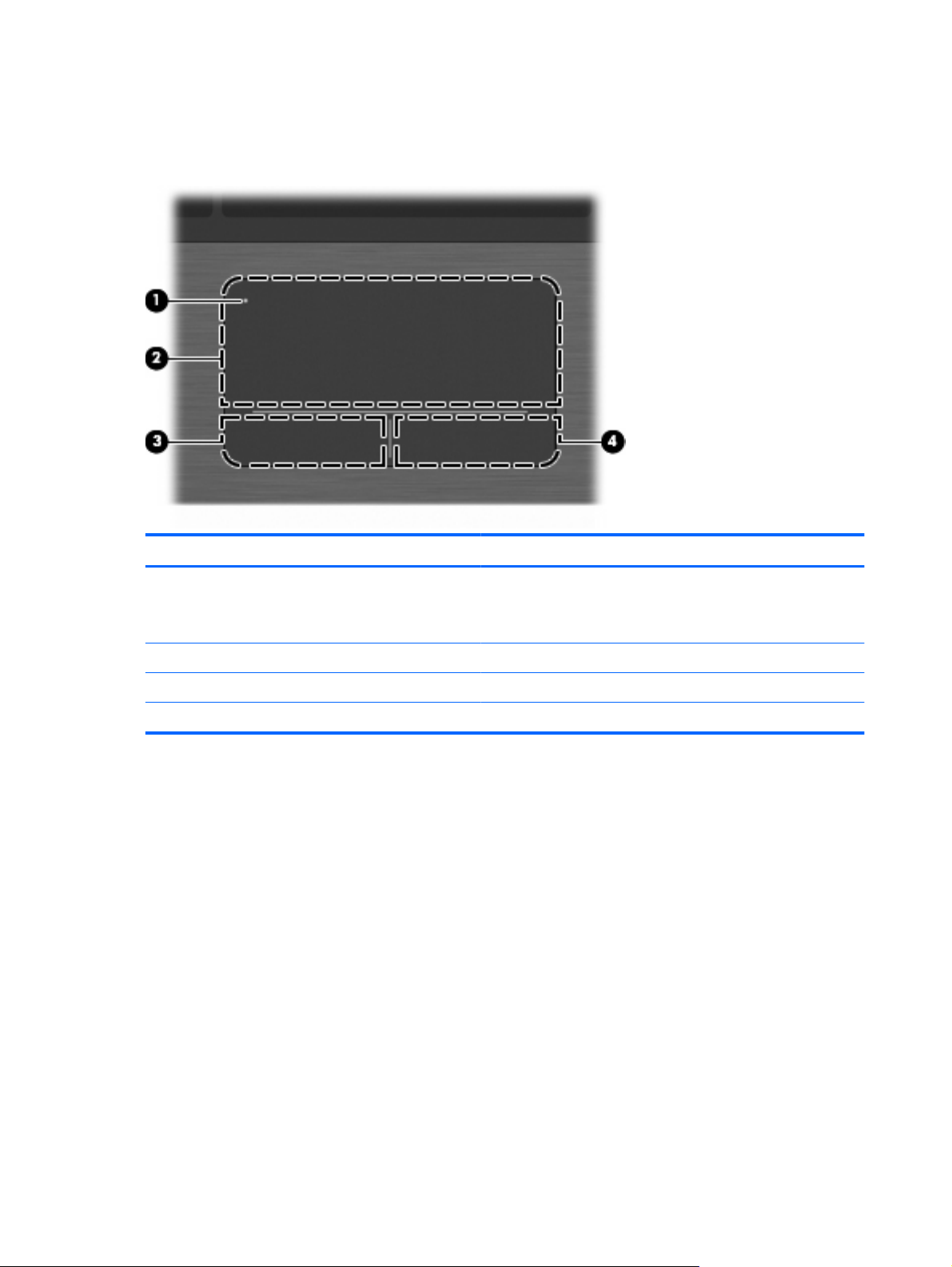
TouchPad
Component Description
(1) TouchPad off indicator To turn the TouchPad on and off, quickly double-tap the TouchPad
(2) TouchPad Moves the pointer and selects or activates items on the screen.
(3) Left TouchPad control Functions like the left button on an external mouse.
(4) Right TouchPad control Functions like the right button on an external mouse.
off indicator.
NOTE: When the TouchPad is on, the light is off.
8 Chapter 2 External component identification
Page 17
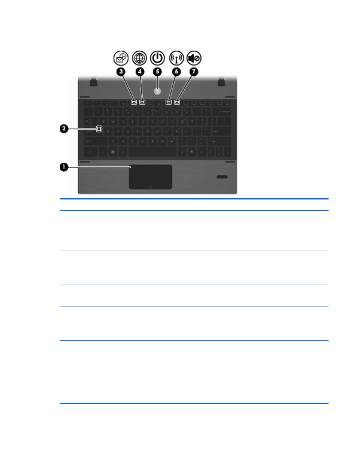
Lights
Component Description
(1) TouchPad off indicator
(2) Caps lock light On: Caps lock is on.
(3) HP QuickLook light
(4) HP QuickWeb light
(5) Power light
(6) Wireless light
(7) Sound mute light
Off: the TouchPad is on.
●
Amber: the TouchPad is off.
●
To switch between active and inactive, quickly double-tap the
TouchPad off indicator.
On: QuickLook is on.
●
Off: QuickLook is off.
●
On: QuickWeb is on.
●
Off: QuickWeb is off.
●
On: The computer is on.
●
Blinking: The computer is in the Sleep state.
●
Off: The computer is off or in Hibernation.
●
White: An integrated wireless device, such as a wireless local
●
area network (WLAN) device, HP Mobile Broadband Module
(select models only), and/or a Bluetooth® device (select
models only), is on.
Amber: All wireless devices are off.
●
On: The speaker sound is muted.
●
Off: The speaker sound is not muted.
●
Top components 9
Page 18
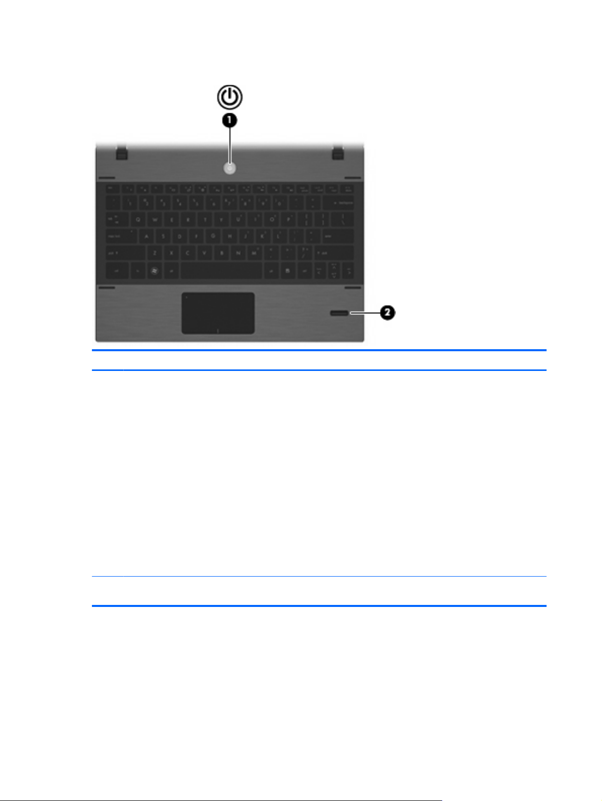
Power button and fingerprint reader
Component Description
(1) Power button
(2) Fingerprint reader (select models only) Allows a fingerprint logon to Windows, instead of a
When the computer is off, press the button to turn on
●
the computer.
When the computer is on, press the button to shut
●
down the computer.
NOTE: Although you can shut down the computer
with the power button, the recommended procedure
is to use the Windows Shut Down command.
When the computer is in the Sleep state, press the
●
button briefly to exit Sleep.
When the computer is in Hibernation, press the
●
button briefly to exit Hibernation.
If the computer has stopped responding and Windows
shutdown procedures are ineffective, press and hold the
power button for at least 5 seconds to turn off the
computer.
password logon.
10 Chapter 2 External component identification
Page 19
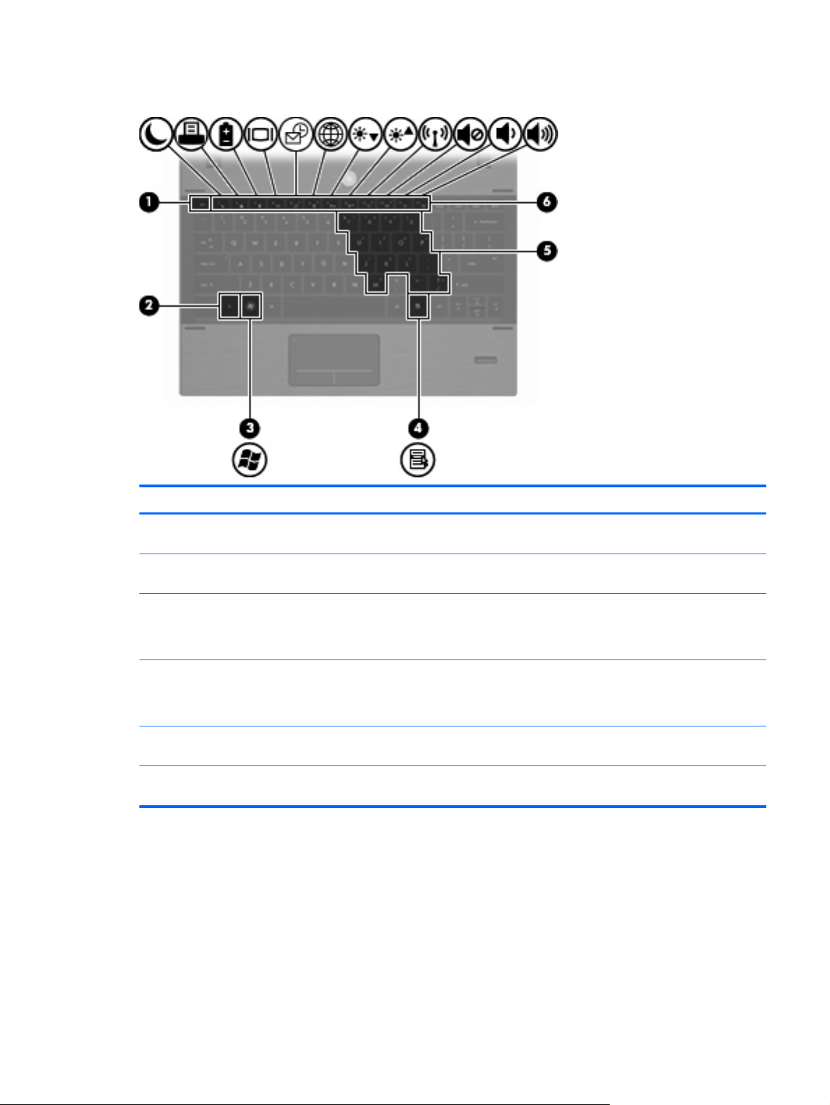
Keys
Component Description
(1) esc key Displays system information when pressed in combination with the
fn key.
(2) fn key Executes frequently used system functions when pressed in
combination with a function key or the esc key.
(3) Windows logo key Displays the Windows Start menu.
NOTE: This feature does not exist if you are using the Linux
operating system.
(4) Windows applications key Displays a shortcut menu for items beneath the pointer.
NOTE: This feature does not exist if you are using the Linux
operating system.
(5) Embedded numeric keypad keys When the keypad has been enabled, it can be used like the keys
on an external numeric keypad.
(6) Function keys Execute frequently used system functions when pressed in
combination with the fn key.
Top components 11
Page 20

Front components
Component Description
(1) Drive light
(2) Speakers (2) Produce sound.
(3) Vent Enables airflow to cool internal components.
White: The hard drive is being accessed.
●
Amber: HP 3D DriveGuard has temporarily parked the hard
●
drive.
NOTE: The computer fan starts up automatically to cool internal
components and prevent overheating. It is normal for the internal
fan to cycle on and off during routine operation.
12 Chapter 2 External component identification
Page 21
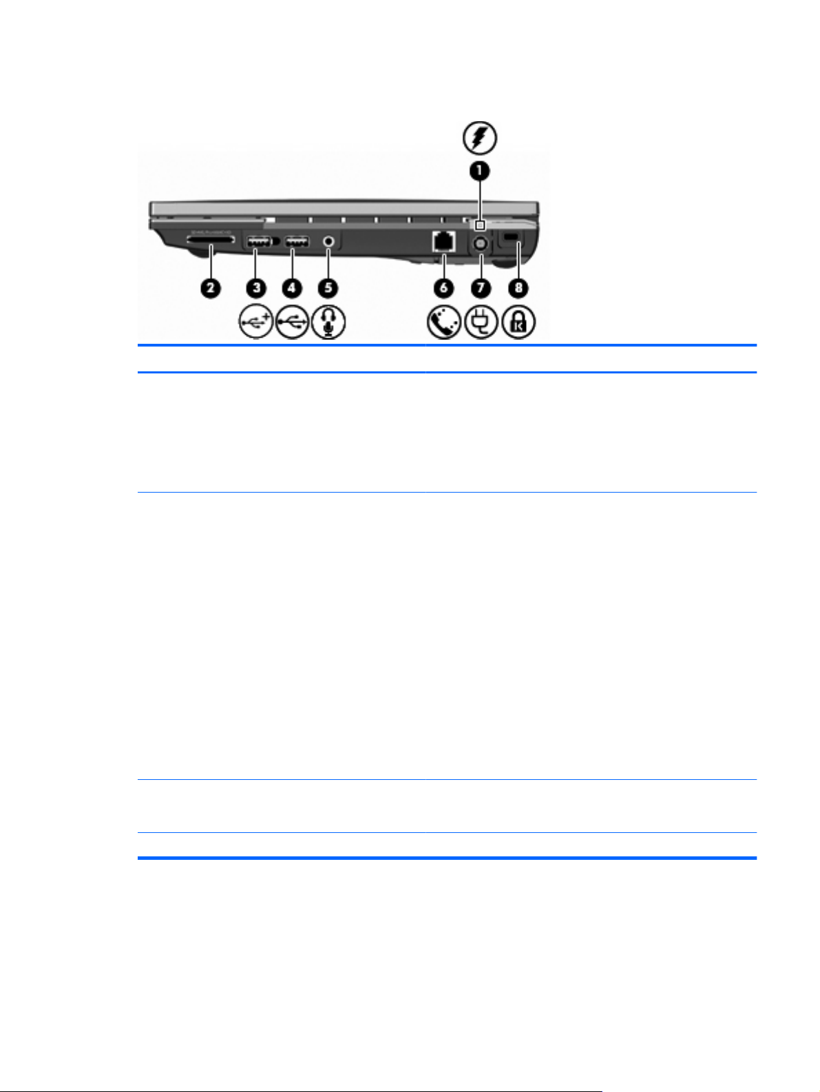
Right-side components
Component Description
(1) Battery light
(2) Media Card Reader Supports the following optional digital card formats:
Amber: A battery is charging.
●
White: A battery is close to full charge capacity.
●
Off: If the computer is plugged into an external power source,
●
the light turns off when the battery is fully charged. If the
computer is not plugged into an external power source, the
light stays off until the battery reaches a low battery level.
Memory Stick (MS)
●
Memory Stick Pro (MSP)
●
Memory Stick Duo (adapter required)
●
Memory Stick Duo Pro (adapter required)
●
MultiMediaCard (MMC)
●
MultiMediaCard Plus
●
Secure Digital (SD) Memory Card
●
SD High Capacity (HC) Memory Card
●
microSD Memory Card (adapter required)
●
xD-Picture Card (XD)
●
(3) Powered USB port Provides power to a USB device, such as an optional external
MultiBay or an optional external optical drive, if used with a powered
USB cable.
(4) USB port Connects optional USB devices.
Right-side components 13
Page 22

Component Description
(5) Audio-out (headphone)/Audio-in (microphone)
jack
(6) RJ-11 (modem) jack Connects a modem cable.
(7) Power connector Connects an AC adapter.
(8) Security cable slot Attaches an optional security cable to the computer.
Produces sound when connected to optional powered stereo
speakers, headphones, ear buds, a headset, or television audio.
Also connects an optional headset microphone.
NOTE: When a device is connected to the headphone jack, the
computer speakers are disabled.
WARNING! To reduce the risk of personal injury, adjust the
volume before putting on headphones, earbuds, or a headset. For
additional safety information, refer to the Regulatory, Safety, and
Environmental Notices.
NOTE: The security cable is designed to act as a deterrent, but
it may not prevent the computer from being mishandled or stolen.
14 Chapter 2 External component identification
Page 23
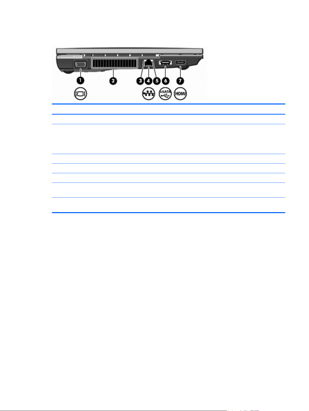
Left-side components
Component Description
(1) External monitor port Connects an external VGA monitor or projector.
(2) Vent Enables airflow to cool internal components.
(3) Network activity light Amber: Data is being transmitted over the network.
(4) RJ-45 (network) jack Connects a network cable.
(5) Network connection light Green: The computer is connected to the network.
(6) USB/eSATA port Connects a high-performance eSATA component, such as an
NOTE: The computer fan starts up automatically to cool internal
components and prevent overheating. It is normal for the internal
fan to cycle on and off during routine operation.
eSATA external hard drive, or connects an optional USB device.
(7) HDMI port Connects an optional video or audio device, such as a high-
definition television, or any compatible digital or audio component.
Left-side components 15
Page 24
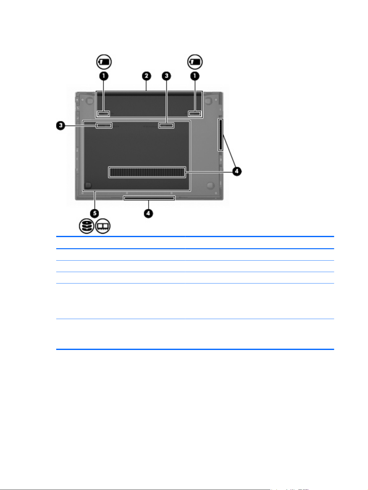
Bottom components
Component Description
(1) Battery release latches (2) Release the battery from the battery bay.
(2) Battery bay Holds the battery and the subscriber identity module (SIM).
(3) Service access door release latches (2). Release the service access door.
(4) Vents (3) Enable airflow to cool internal components.
NOTE: The computer fan starts up automatically to cool internal
components and prevent overheating. It is normal for the internal
fan to cycle on and off during routine operation.
(5) Service access bay Provides access to the hard drive, 2 memory module slots, the
wireless local area network (WLAN) module, and the HP Mobile
Broadband Module (select models only; not supported by the Linux
operating system).
16 Chapter 2 External component identification
Page 25
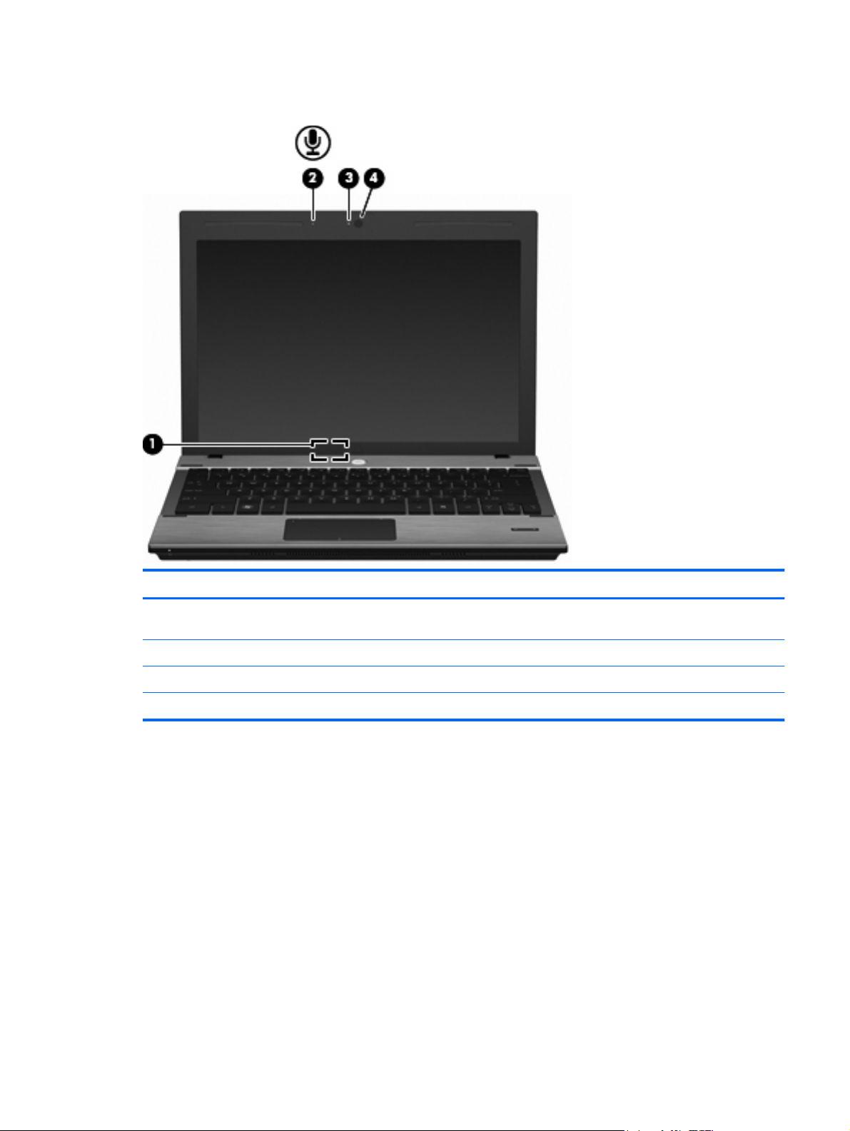
Display components
Component Description
(1) Internal display switch Turns off the display and initiates Sleep if the display is closed while
the power is on.
(2) Internal microphone Records sound.
(3) Webcam light (select models only) On: The webcam is in use.
(4) Webcam (select models only) Records audio and video and captures still photographs.
Display components 17
Page 26
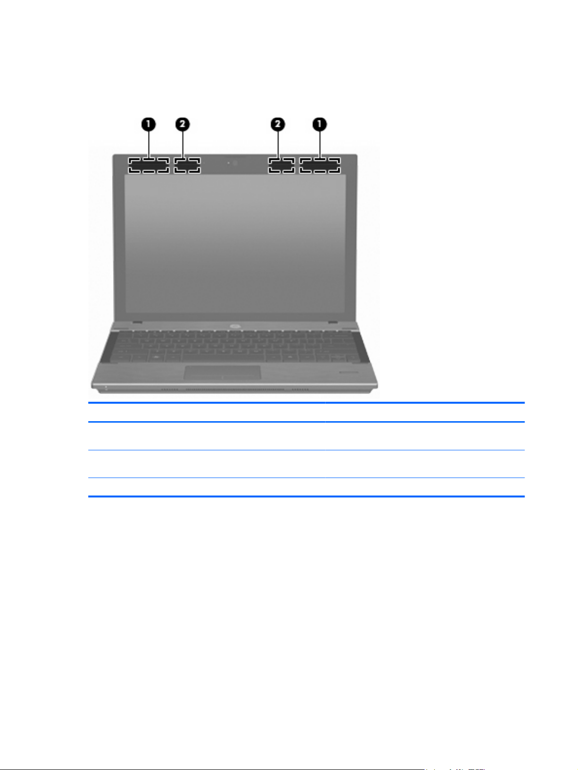
Wireless antennas
Your computer has at least two antennas that send and receive signals from one or more wireless
devices.
Component Description
(1) WWAN antennas (2)* (select models only) Send and receive wireless signals to communicate with
wireless wide area networks (WWANs).
(2) WLAN antennas (2)* Send and receive wireless signals to communicate with
* For optimal transmission, keep the area immediately around the antennas free from obstructions.
wireless local area networks (WLANs).
To see wireless regulatory notices, refer to the section of the Regulatory, Safety, and Environmental
Notices that applies to your country or region. These notices are located in Help and Support.
18 Chapter 2 External component identification
Page 27
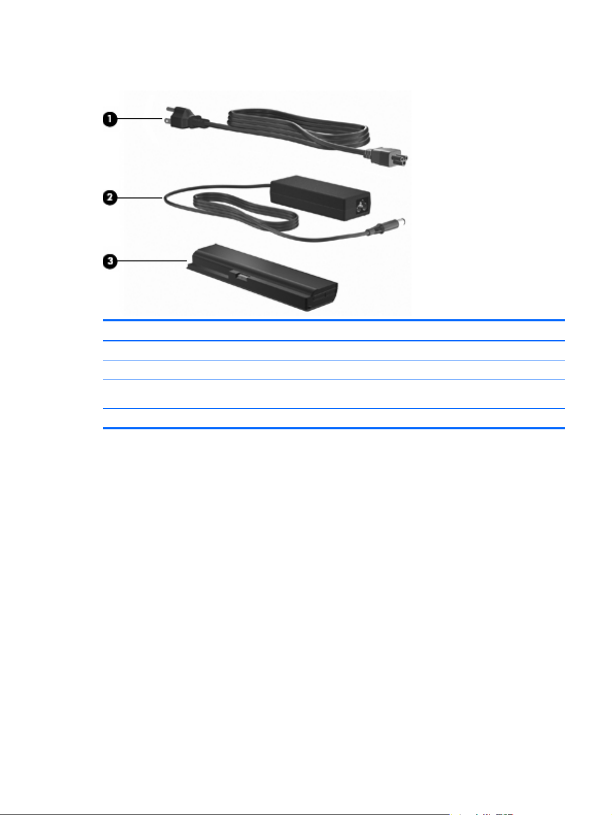
Additional hardware components
Component Description
(1) Power cord* Connects an AC adapter to an AC outlet.
(2) AC adapter Converts AC power to DC power.
(3) Battery Powers the computer when the computer is not plugged into
external power.
*Power cords vary in appearance by country or region.
Additional hardware components 19
Page 28
3 Illustrated parts catalog
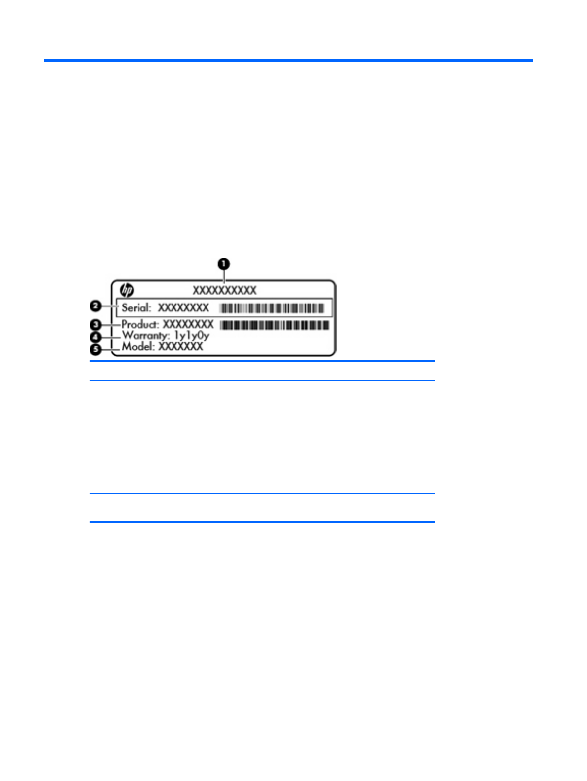
Serial number label location
When you order parts or request information, the serial number label, located inside the battery bay,
provides important information that you may need when contacting technical support.
Component Description
(1) Part number The number that provides specific information about the
product's hardware components. The part number
helps a service technician to determine what
components and parts are needed.
(2) Serial number An alphanumeric number that is unique to each
product.
(3) Product information The product name affixed to the front of your computer.
(4) Warranty period The duration of the warranty period for this computer.
(5) Model description The alphanumeric identifier you need to locate
documents, drivers, and support for your computer.
20 Chapter 3 Illustrated parts catalog
Page 29
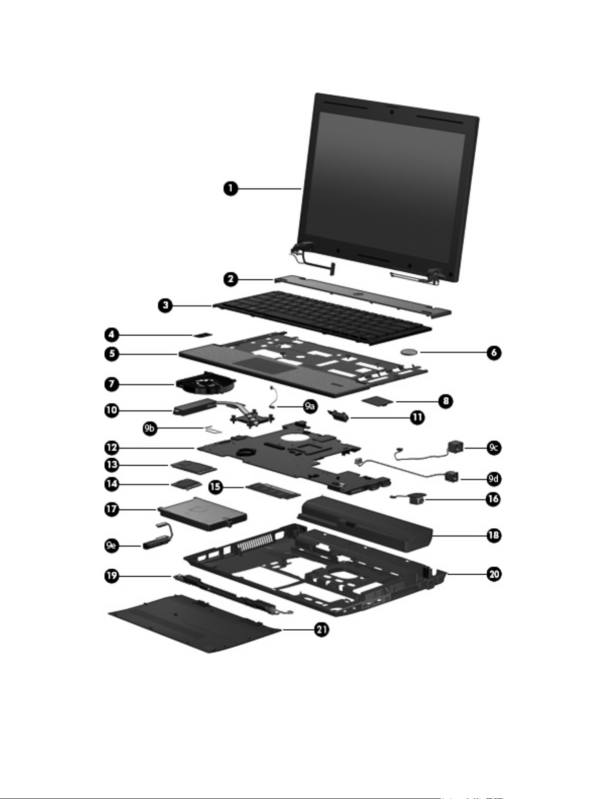
Computer major components
Computer major components 21
Page 30

Item Description Spare part number
(1) 30.734-cm (12.1-in) Display assembly (includes 2 WLAN antennas and cables and, on select computer models, 2
WWAN antennas and cables)
NOTE: WWAN is available only on select models.
(2) Switch cover 610832-001
(3) Keyboard
(4) SIM (provided by your wireless vendor for use with WWAN option)
(5) Top cover
For use with models with fingerprint readers (includes TouchPad assembly) 610833-001
For use with models without fingerprint readers (includes TouchPad assembly) 610834-001
WXGA AntiGlare display assembly without webcam
●
WXGA AntiGlare display assembly with webcam
●
WXGA AntiGlare display assembly with webcam and WWAN
●
WXGA BrightView display assembly without webcam
●
WXGA BrightView display assembly with webcam
●
For use in Japan
●
For use in South Korea
●
For use in Taiwan
●
For use in Thailand
●
For use in the United States
●
610807-001
610808-001
610809-001
610810-001
610811-001
610826-291
610826-AD1
610826-AB1
610826-281
610826-001
(6) RTC battery 599516-001
(7) Fan 610824-001
(8) Modem module
NOTE: The modem module spare part kit does not include a modem module cable. The
modem module cable is included in the Cable Kit, spare part number 610806-001. See Cable
Kit on page 27 for more Cable Kit spare part information.
High-speed 56K modem 510100-011
Cable Kit 610806-001
(9a) Bluetooth module cable
(9b) TouchPad cable
(9c) Power connector cable
(9d) RJ-11 (modem) cable
(9e) Hard drive connector cable
(10) Heat sink 610825-001
22 Chapter 3 Illustrated parts catalog
Page 31

Item Description Spare part number
(11) Bluetooth module
NOTE: The Bluetooth module spare part kit does not include a Bluetooth module cable. The
Bluetooth module cable is included in the Cable Kit, part number 610806-001. See Cable Kit
on page 27 for more Cable Kit spare part information.
(12) System board (includes processor and replacement thermal material)
(13) WWAN module, EVDO Birlion HSPA 531993-001
(14) WLAN module
Intel Centrino Wireless-N 1000 802.11b/g/n 1x2
Includes Intel Celeron U3400 1.06-GHz processor
●
Includes Intel Arrandale I3-350M 2.26-GHz processor
●
Includes Intel Arrandale I5-450M 2.4-GHz processor
●
Includes Intel Arrandale I5-520M 2.4-GHz processor
●
Includes Intel Arrandale I5-540M 2.53-GHz processor
●
For use in Australia, Bangladesh, Bhutan, Brunei, Cambodia, East Timor, Fiji, Hong Kong,
India, Indonesia, Japan, Kiribati, Laos, Malaysia, Maldives, Marshall Islands, Micronesia,
Nauru, Nepal, New Zealand, Pakistan, Palau, Papua New Guinea, the People's Republic of
China, the Philippines, Samoa, Singapore, Solomon Islands, South Korea, Sri Lanka, Taiwan,
Thailand, Tonga, Tuvalu, and Vietnam
537921-001
614536-001
610803-001
614534-001
614535-001
611373-001
593065-001
Intel WiFi Link 6200 802.11a/b/g/n
For use in Australia, Bangladesh, Bhutan, Brunei, Cambodia, East Timor, Fiji, Hong Kong,
India, Japan, Kiribati, Laos, Malaysia, Maldives, Marshall Islands, Micronesia, Nauru, Nepal,
New Zealand, Pakistan, Palau, Papua New Guinea, the People's Republic of China, the
Philippines, Samoa, Singapore, Solomon Islands, South Korea, Sri Lanka, Taiwan, Thailand,
Tonga, Tuvalu, and Vietnam
Broadcom 4313 802.11b/g/n 1x1 WiFi Adapter
For use in Australia, Bangladesh, Bhutan, Brunei, Cambodia, East Timor, Fiji, Hong Kong,
India, Indonesia, Japan, Kiribati, Laos, Malaysia, Maldives, Marshall Islands, Micronesia,
Nauru, Nepal, New Zealand, Pakistan, Palau, Papua New Guinea, the People's Republic of
China, the Philippines, Samoa, Singapore, Solomon Islands, South Korea, Sri Lanka, Taiwan,
Thailand, Tonga, Tuvalu, and Vietnam
Broadcom 4322 802.11a/b/g/n 2x2 WiFi Adapter
For use in Australia, Bangladesh, Bhutan, Brunei, Cambodia, Fiji, Hong Kong, India, Indonesia,
Japan, Kiribati, Laos, Malaysia, Maldives, Marshall Islands, Micronesia, Nauru, Nepal, New
Zealand, Pakistan, Palau, Papua New Guinea, the People's Republic of China, the Philippines,
Samoa, Singapore, Solomon Islands, South Korea, Sri Lanka, Taiwan, Thailand, Tonga,
Tuvalu, and Vietnam
(15) Memory module (DDR3 PC3-10600 SDRAM, 1333 MHz, shared)
4096-MB 599092-001
2048-MB 581096-001
1024-MB 598859-001
572509-001
593836-001
518434-002
(16) Audio board (includes cable) 610805-001
(17) Hard drive (includes hard drive bracket)
Computer major components 23
Page 32

Item Description Spare part number
SATA, 9.5-mm, 6.35-cm (2.5-in) hard drives
640-GB, 7200-rpm 610821-001
500-GB, 7200-rpm 610820-001
320-GB, 7200-rpm 610819-001
250-GB, 7200-rpm 610818-001
4.57-cm (1.8-in) solid-state drive
80-GB 610823-001
(18) Battery
4-cell, 41-Wh (2.8-Ah) Li-on 535630-001
6-cell, 62-Wh (2.8-Ah) Li-ion 596236-001
(19) Speakers 610831-001
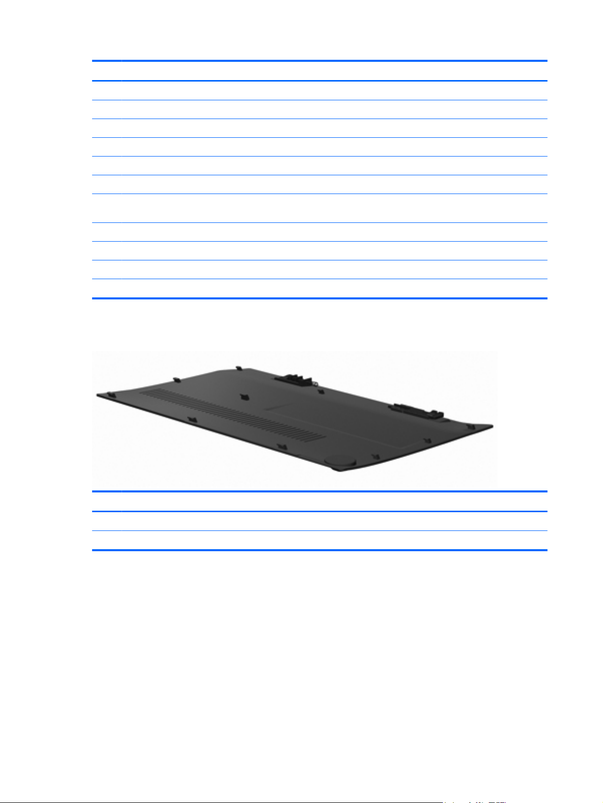
(20) Base enclosure 610801-001
(21) Service access door
NOTE: The service access door is included in the Plastics Kit, spare part number
610828-001. See Plastics Kit on page 26 for more Plastics Kit spare part information.
24 Chapter 3 Illustrated parts catalog
Page 33

Display assembly components
Item Description Spare part number
(1) Display bezel
For displays with webcam
●
For displays without webcam 610815-001
●
610814-001
Display assembly components 25
Page 34
Item Description Spare part number
(2) Display panel
(3) Display cable (includes microphone and, on select models, webcam connector)
●
●
(4) Display Hinge Kit (includes left and right display hinges) 610817-001
(5) Webcam module 610835-001
(6) WWAN antennas and cables (included with display back cover used with WWAN
option)
(7) WLAN antennas and cables (included with display back cover)
(8) Display back cover
●
●
Plastics Kit
For displays with webcam
For displays without webcam
For displays without WWAN
For displays with WWAN 610813-001
610816-001
614742-001
610812-001
Item Description Spare part number
Plastics Kit: 610828-001
Service access door
26 Chapter 3 Illustrated parts catalog
Page 35

Cable Kit
Item Description Spare part number
Cable Kit: 610806-001
(1) Hard drive connector cable
(2) Bluetooth cable
(3) RJ-11 (modem) jack cable
(4) Power cable
(5) TouchPad cable
Cable Kit 27
Page 36

Mass storage devices
Item Description Spare part number
(1) Hard drive (includes bracket)
640-GB, 7200-rpm 610821-001
500-GB, 7200-rpm 610820-001
320-GB, 7200-rpm 610819-001
250-GB, 7200-rpm 610818-001
(2) Solid-state drive (includes bezel)
80-GB
610823-001
28 Chapter 3 Illustrated parts catalog
Page 37

Miscellaneous parts
Description Spare part number
AC adapters
65-W, 3-pin Smart AC Adapter for use in all countries and regions except India
65-W, 3-pin Smart AC Adapter for use only in India 609948-001
Power cords (AC power, 3-pin, black, 1.83-m)
For use in Australia
●
For use in India
●
For use in Japan
●
For use in North America
●
For use in the People's Republic of China
●
For use in South Korea
●
For use in Taiwan
●
Rubber Kit (includes 4 base enclosure feet, display screw covers, and Bluetooth rubber cage) 610829-001
Screw kit–includes:
Phillips M2.5x5.0
●
Phillips M2.0x3.0
●
Phillips M2.0x2.5
●
Phillips M3.0x3.5
●
609939-001
490371-011
490371-D61
490371-291
490371-001
490371-AA1
490371-AD1
490371-AB1
610830-001
Miscellaneous parts 29
Page 38

Sequential part number listing
Spare part
number
490371-001 Power cord (AC power, 3-pin, black, 1.83-m), for use in North America
490371-011 Power cord (AC power, 3-pin, black, 1.83-m), for use in Austria
490371-291 Power cord (AC power, 3-pin, black,1.83-m), for use in Japan
490371-AA1 Power cord (AC power, 3-pin, black, 1.83-m), for use in the People's Republic of China
490371-AB1 Power cord (AC power, 3-pin, black, 1.83-m), for use in Taiwan
490371-AD1 Power cord (AC power, 3-pin, black,1.83-m), for use in South Korea
490371-D61 Power cord (AC power, 3-pin, black, 1.83-m), for use in India
510100-011 High-speed 56K modem
518434-002 Broadcom 4322 802.11a/b/g/n 2x2 WiFi Adapter
531993-001 WWAN module, EVDO Birlion HSPA
535630-001 Battery, 4-cell, 41-Wh (2.8-Ah) Li-ion
537921-001 Bluetooth module (without cable). The Bluetooth cable is included in the Cable Kit, spare part number
572509-001 Intel WiFi Link 6200 802.11a/b/g/n for use in Australia, Bangladesh, Bhutan, Brunei, Cambodia, East Timor,
Description
610806-001.
Fiji, Hong Kong, India, Japan, Kiribati, Laos, Malaysia, Maldives, Marshall Islands, Micronesia, Nauru, Nepal,
New Zealand, Pakistan, Palau, Papua New Guinea, the People's Republic of China, the Philippines, Samoa,
Singapore, Solomon Islands, South Korea, Sri Lanka, Taiwan, Thailand, Tonga, Tuvalu, and Vietnam
581096-001 Memory module (DDR3 PC3-10600 SDRAM, 1333 MHz, shared), 2048-MB
593065-001 Intel Centrino Wireless-N 1000 802.11b/g/n 1x2 for use in Australia, Bangladesh, Bhutan, Brunei, Cambodia,
East Timor, Fiji, Hong Kong, India, Indonesia, Japan, Kiribati, Laos, Malaysia, Maldives, Marshall Islands,
Micronesia, Nauru, Nepal, New Zealand, Pakistan, Palau, Papua New Guinea, the People's Republic of
China, the Philippines, Samoa, Singapore, Solomon Islands, South Korea, Sri Lanka, Taiwan, Thailand,
Tonga, Tuvalu, and Vietnam
593836-001 Broadcom 4313 802.11b/g/n 1x1 WiFi Adapter for use in Australia, Bangladesh, Bhutan, Brunei, Cambodia,
East Timor, Fiji, Hong Kong, India, Indonesia, Japan, Kiribati, Laos, Malaysia, Maldives, Marshall Islands,
Micronesia, Nauru, Nepal, New Zealand, Pakistan, Palau, Papua New Guinea, the People's Republic of
China, the Philippines, Samoa, Singapore, Solomon Islands, South Korea, Sri Lanka, Taiwan, Thailand,
Tonga, Tuvalu, and Vietnam
596236-001 Battery, 6-cell, 62-Wh (2.8-Ah) Li-ion
598859-001 Memory module (DDR3 PC3-10600 SDRAM, 1333 MHz, shared), 1024-MB
599092-001 Memory module (DDR3 PC3-10600 SDRAM, 1333 MHz, shared), 4096-MB
599516-001 RTC battery
609939-001 65-W, 3-pin Smart AC adapter for use in all countries and regions except India
609948-001 65-W, 3-pin Smart AC adapter for use only in India
610801-001 Base enclosure
610803-001 System board (includes Intel Arrandale i3-350M 2.26-GHz processor and replacement thermal material)
610805-001 Audio board (includes cable)
30 Chapter 3 Illustrated parts catalog
Page 39

Spare part
number
610806-001 Cable Kit (See Cable Kit on page 27 for more Cable Kit spare part information.)
610807-001 Display assembly, WXGA AntiGlare without webcam
610808-001 Display assembly, WXGA AntiGlare with webcam
610809-001 Display assembly, WXGA AntiGlare with webcam and WWAN
610810-001 Display assembly, BrightView without webcam
610811-001 Display assembly, BrightView with webcam
610812-001 Display back cover for displays without WWAN
610813-001 Display back cover for displays with WWAN
610814-001 Display bezel for displays with webcam
610815-001 Display bezel for displays without webcam
610816-001 Display cable for displays with webcam (includes microphone and webcam connector)
610817-001 Display Hinge Kit (includes left and right display hinges)
610818-001 Hard drive, 250-GB, 7200-rpm (includes hard drive bracket)
610819-001 Hard drive, 320-GB, 7200-rpm (includes hard drive bracket)
610820-001 Hard drive, 500-GB, 7200-rpm (includes hard drive bracket)
Description
610821-001 Hard drive, 640-GB, 7200-rpm (includes hard drive bracket)
610823-001 Solid-state drive, 4.57-cm (1.8-in), 80-GB (includes hard drive bracket)
610824-001 Fan
610825-001 Heat sink
610826-001 Keyboard for use in the United States
610826-281 Keyboard for use in Thailand
610826-291 Keyboard for use in Japan
610826-AB1 Keyboard for use in Taiwan
610826-AD1 Keyboard for use in South Korea
610828-001 Plastics Kit (includes service access door)
610829-001 Rubber Kit (includes 4 base enclosure feet, display screw covers, and Bluetooth rubber cage)
610830-001 Screw Kit (See Miscellaneous parts on page 29 for more Screw Kit spare part information.)
610831-001 Speaker assembly
610832-001 Switch cover
610833-001 Top cover, for use with models with fingerprint readers (includes TouchPad assembly)
610834-001 Top cover, for use with models without fingerprint readers (includes TouchPad assembly)
610835-001 Webcam module
611373-001 System board (includes Intel Arrandale i5-540M 2.53-GHz processor and replacement thermal material)
614534-001 System board (includes Intel Arrandale i5-450M 2.4-GHz processor and replacement thermal material)
Sequential part number listing 31
Page 40

Spare part
number
614535-001 System board (includes Intel Arrandale i5-520M 2.4-GHz processor and replacement thermal material)
614536-001 System board (includes Intel Celeron U3400 1.06-GHz processor and replacement thermal material)
614742-001 Display cable for displays without webcam (includes microphone)
Description
32 Chapter 3 Illustrated parts catalog
Page 41

4 Removal and replacement procedures
Preliminary replacement requirements
Tools required
You will need the following tools to complete the removal and replacement procedures:
Flat-bladed screwdriver
●
P0 and P1 screwdrivers
●
Service considerations
The following sections include some of the considerations that you must keep in mind during
disassembly and assembly procedures.
NOTE: As you remove each subassembly from the computer, place the subassembly (and all
accompanying screws) away from the work area to prevent damage.
Plastic parts
CAUTION: Using excessive force during disassembly and reassembly can damage plastic parts. Use
care when handling the plastic parts. Apply pressure only at the points designated in the maintenance
instructions.
Preliminary replacement requirements 33
Page 42

Cables and connectors
CAUTION: When servicing the computer, be sure that cables are placed in their proper locations
during the reassembly process. Improper cable placement can damage the computer.
Cables must be handled with extreme care to avoid damage. Apply only the tension required to unseat
or seat the cables during removal and insertion. Handle cables by the connector whenever possible. In
all cases, avoid bending, twisting, or tearing cables. Be sure that cables are routed in such a way that
they cannot be caught or snagged by parts being removed or replaced. Handle flex cables with extreme
care; these cables tear easily.
Drive handling
CAUTION: Drives are fragile components that must be handled with care. To prevent damage to the
computer, damage to a drive, or loss of information, observe these precautions:
Before removing or inserting a hard drive, shut down the computer. If you are unsure whether the
computer is off or in Hibernation, turn the computer on, and then shut it down through the operating
system.
Before handling a drive, be sure that you are discharged of static electricity. While handling a drive,
avoid touching the connector.
Before removing a diskette drive or optical drive, be sure that a diskette or disc is not in the drive and
be sure that the optical drive tray is closed.
Handle drives on surfaces covered with at least one inch of shock-proof foam.
Avoid dropping drives from any height onto any surface.
After removing a hard drive, an optical drive, or a diskette drive, place it in a static-proof bag.
Avoid exposing a hard drive to products that have magnetic fields, such as monitors or speakers.
Avoid exposing a drive to temperature extremes or liquids.
If a drive must be mailed, place the drive in a bubble pack mailer or other suitable form of protective
packaging and label the package “FRAGILE.”
34 Chapter 4 Removal and replacement procedures
Page 43

Grounding guidelines
Electrostatic discharge damage
Electronic components are sensitive to electrostatic discharge (ESD). Circuitry design and structure
determine the degree of sensitivity. Networks built into many integrated circuits provide some protection,
but in many cases, ESD contains enough power to alter device parameters or melt silicon junctions.
A discharge of static electricity from a finger or other conductor can destroy static-sensitive devices or
microcircuitry. Even if the spark is neither felt nor heard, damage may have occurred.
An electronic device exposed to ESD may not be affected at all and can work perfectly throughout a
normal cycle. Or the device may function normally for a while, then degrade in the internal layers,
reducing its life expectancy.
CAUTION: To prevent damage to the computer when you are removing or installing internal
components, observe these precautions:
Keep components in their electrostatic-safe containers until you are ready to install them.
Use nonmagnetic tools.
Before touching an electronic component, discharge static electricity by using the guidelines described
in this section.
Avoid touching pins, leads, and circuitry. Handle electronic components as little as possible.
If you remove a component, place it in an electrostatic-safe container.
The following table shows how humidity affects the electrostatic voltage levels generated by different
activities.
CAUTION: A product can be degraded by as little as 700 V.
Typical electrostatic voltage levels
Event 10% 40% 55%
Walking across carpet 35,000 V 15,000 V 7,500 V
Walking across vinyl floor 12,000 V 5,000 V 3,000 V
Motions of bench worker 6,000 V 800 V 400 V
Removing DIPS from plastic tube 2,000 V 700 V 400 V
Removing DIPS from vinyl tray 11,500 V 4,000 V 2,000 V
Removing DIPS from Styrofoam 14,500 V 5,000 V 3,500 V
Removing bubble pack from PCB 26,500 V 20,000 V 7,000 V
Packing PCBs in foam-lined box 21,000 V 11,000 V 5,000 V
Relative humidity
Preliminary replacement requirements 35
Page 44

Packaging and transporting guidelines
Follow these grounding guidelines when packaging and transporting equipment:
To avoid hand contact, transport products in static-safe tubes, bags, or boxes.
●
Protect ESD-sensitive parts and assemblies with conductive or approved containers or packaging.
●
Keep ESD-sensitive parts in their containers until the parts arrive at static-free workstations.
●
Place items on a grounded surface before removing items from their containers.
●
Always be properly grounded when touching a component or assembly.
●
Store reusable ESD-sensitive parts from assemblies in protective packaging or nonconductive
●
foam.
Use transporters and conveyors made of antistatic belts and roller bushings. Be sure that
●
mechanized equipment used for moving materials is wired to ground and that proper materials are
selected to avoid static charging. When grounding is not possible, use an ionizer to dissipate
electric charges.
Workstation guidelines
Follow these grounding workstation guidelines:
Cover the workstation with approved static-shielding material.
●
Use a wrist strap connected to a properly grounded work surface and use properly grounded tools
●
and equipment.
Use conductive field service tools, such as cutters, screwdrivers, and vacuums.
●
When fixtures must directly contact dissipative surfaces, use fixtures made only of static-safe
●
materials.
Keep the work area free of nonconductive materials, such as ordinary plastic assembly aids and
●
Styrofoam.
Handle ESD-sensitive components, parts, and assemblies by the case or PCM laminate. Handle
●
these items only at static-free workstations.
Avoid contact with pins, leads, or circuitry.
●
Turn off power and input signals before inserting or removing connectors or test equipment.
●
36 Chapter 4 Removal and replacement procedures
Page 45

Equipment guidelines
Grounding equipment must include either a wrist strap or a foot strap at a grounded workstation.
When seated, wear a wrist strap connected to a grounded system. Wrist straps are flexible straps
●
with a minimum of one megohm ±10% resistance in the ground cords. To provide proper ground,
wear a strap snugly against the skin at all times. On grounded mats with banana-plug connectors,
use alligator clips to connect a wrist strap.
When standing, use foot straps and a grounded floor mat. Foot straps (heel, toe, or boot straps)
●
can be used at standing workstations and are compatible with most types of shoes or boots. On
conductive floors or dissipative floor mats, use foot straps on both feet with a minimum of one
megohm resistance between the operator and ground. To be effective, the conductive strips must
be worn in contact with the skin.
The following grounding equipment is recommended to prevent electrostatic damage:
Antistatic tape
●
Antistatic smocks, aprons, and sleeve protectors
●
Conductive bins and other assembly or soldering aids
●
Nonconductive foam
●
Conductive tabletop workstations with ground cords of one megohm resistance
●
Static-dissipative tables or floor mats with hard ties to the ground
●
Field service kits
●
Static awareness labels
●
Material-handling packages
●
Nonconductive plastic bags, tubes, or boxes
●
Metal tote boxes
●
Electrostatic voltage levels and protective materials
●
The following table lists the shielding protection provided by antistatic bags and floor mats.
Material Use Voltage protection level
Antistatic plastic Bags 1,500 V
Carbon-loaded plastic Floor mats 7,500 V
Metallized laminate Floor mats 5,000 V
Preliminary replacement requirements 37
Page 46
Component replacement procedures
This section provides removal and replacement procedures.
There are as many as 57 screws, in 5 different sizes, that must be removed, replaced, or loosened when
servicing the computer. Make special note of each screw size and location during removal and
replacement.
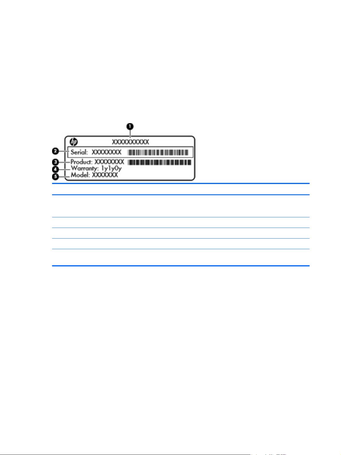
Service tag
When you order parts or request information, provide the computer serial number and model number
provided on the service tag, located inside the battery bay.
Component Description
(1) Part number The number that provides specific information about the product's hardware
(2) Serial number An alphanumeric number that is unique to each product.
(3) Product information The product name affixed to the front of your computer.
(4) Warranty period The duration of the warranty period for this computer.
(5) Model description The alphanumeric identifier you need to locate documents, drivers, and support for
components. The part number helps a service technician to determine what
components and parts are needed.
your computer.
38 Chapter 4 Removal and replacement procedures
Page 47

Computer feet
Description Spare part number
Rubber Kit (includes computer feet) 610829-001
The computer feet are adhesive-backed rubber pads. There are 4 rubber feet that attach to the base
enclosure in the locations shown in the following illustration.
Component replacement procedures 39
Page 48

Battery
Description Spare part number
4-cell, 41-Wh (2.8-Ah) Li-on battery 535630-001
6-cell, 62-Wh (2.8-Ah) Li-ion battery 596236-001
Before removing the battery, follow these steps:
1. Shut down the computer. If you are unsure whether the computer is off or in Hibernation, turn the
computer on, and then shut it down through the operating system.
2. Disconnect all external devices connected to the computer.
3. Disconnect the power from the computer by first unplugging the power cord from the AC outlet and
then unplugging the AC adapter from the computer.
Remove the battery:
1. Position the computer upside down on a flat surface with the battery bay toward you.
2. Slide the right lock latch (1) inward. The latch opening is marked red to indicate that the latch is
unlocked.
3. Slide the left release latch (2) inward and hold it in place as you slide and remove the battery (3).
To insert the battery:
1. Turn the computer upside down on a flat surface, with the battery bay toward you.
2. Slide the battery into the battery bay (1) until the battery release latch (2) clicks.
40 Chapter 4 Removal and replacement procedures
Page 49

3. Slide the battery lock (3) to the right to lock the battery into place.
Component replacement procedures 41
Page 50

SIM
NOTE: This section applies only to select models with WWAN capability.
NOTE: If there is a SIM inserted in the SIM slot, it must be removed before disassembling the
computer. Be sure that the SIM is reinserted in the SIM slot after reassembling the computer.
Before removing the SIM, follow these steps:
1. Shut down the computer. If you are unsure whether the computer is off or in Hibernation, turn the
computer on, and then shut it down through the operating system.
2. Disconnect all external devices connected to the computer.
3. Disconnect the power from the computer by first unplugging the power cord from the AC outlet,
and then unplugging the AC adapter from the computer.
4. Remove the battery (see
Remove the SIM:
1. Position the computer upside down with the battery bay toward you.
2. Press in on the SIM (1) to release it from the SIM slot.
3. Remove the SIM (2) from the computer.
Battery on page 40).
Install the SIM by inserting it into the SIM slot until you hear a click. To prevent damage to the connectors,
use minimal force when inserting a SIM.
CAUTION: If a SIM is inserted backwards or upside down, the battery may not snap into place properly
and could damage the SIM and the SIM connector.
WLAN module
Description Spare part number
Intel Centrino Wireless-N 1000 802.11b/g/n 1x2 593065-001
42 Chapter 4 Removal and replacement procedures
Page 51

Description Spare part number
Intel WiFi Link 6200 802.11 a/b/g/n 572509-001
Broadcom 4313 802.11b/g/n 1x1 WiFi Adapter 593836-001
Broadcom 4322 802.11a/b/g/n 2x2 WiFi Adapter 518434-002
CAUTION: To prevent an unresponsive system, replace the wireless module only with a wireless
module authorized for use in the computer by the governmental agency that regulates wireless devices
in your country or region. If you replace the module and then receive a warning message, remove the
module to restore computer functionality, and then contact technical support through Help and Support.
Before removing the WLAN module, follow these steps:
1. Shut down the computer. If you are unsure whether the computer is off or in Hibernation, turn the
computer on, and then shut it down through the operating system.
2. Disconnect all external devices connected to the computer.
3. Disconnect the power from the computer by first unplugging the power cord from the AC outlet and
then unplugging the AC adapter from the computer.
4. Remove the battery (see
Battery on page 40).
Remove the WLAN module:
1. Position the computer upside down with the battery bay toward you.
2. Slide the lock latch (1) on the service access door inward. The latch opening is marked red to
indicate that the latch is unlocked.
3. Slide the left release latch (2) inward and hold it in place as you slide the door toward the battery
bay.
Component replacement procedures 43
Page 52

4. Release the latch and remove the service access door (3).
NOTE: The service access door is available in the Plastics Kit, part number 610828-001.
5. Disconnect the WLAN antenna cables (1) from the terminals on the WLAN module.
NOTE: The black WLAN antenna cable is connected to the WLAN module “Main” terminal. The
white WLAN antenna cable is connected to the WLAN module “Aux” terminal.
6. Remove the PM2.0×3.0 screw (2) that secures the WLAN module to the system board. (The WLAN
module tilts up.)
7. Remove the WLAN module (3) by pulling the module away from the slot at an angle.
NOTE: WLAN modules are designed with a notch (4) to prevent incorrect insertion.
Reverse this procedure to install the WLAN module.
44 Chapter 4 Removal and replacement procedures
Page 53

WWAN module
NOTE: Only select models include a WWAN module (see Product description on page 1).
Description Spare part number
EVDO Birlion HSPA 531993-001
CAUTION: To prevent an unresponsive system, replace the wireless module only with a wireless
module authorized for use in the computer by the governmental agency that regulates wireless devices
in your country or region. If you replace the module and then receive a warning message, remove the
module to restore computer functionality, and then contact technical support through Help and Support.
Before removing the WWAN module, follow these steps:
1. Shut down the computer. If you are unsure whether the computer is off or in Hibernation, turn the
computer on, and then shut it down through the operating system.
2. Disconnect all external devices connected to the computer.
3. Disconnect the power from the computer by first unplugging the power cord from the AC outlet and
then unplugging the AC adapter from the computer.
4. Remove the battery (see
5. Remove the service access door (see
Battery on page 40).
WLAN module on page 42).
Remove the WWAN module:
1. Position the computer upside down with the front toward you.
2. Disconnect the WWAN antenna cables (1) from the terminals on the WWAN module.
NOTE: The red WWAN antenna cable is connected to the WLAN module “Main” terminal. The
blue WWAN antenna cable is connected to the WWAN module “Aux” terminal.
3. Remove the PM2.0×3.0 screw (2) that secures the WWAN module to the system board. (The
WWAN module tilts up.)
Component replacement procedures 45
Page 54

4. Remove the WWAN module (3) by pulling the module away from the slot at an angle.
NOTE: WWAN modules are designed with a notch (4) to prevent incorrect insertion.
Reverse this procedure to install the WWAN module.
46 Chapter 4 Removal and replacement procedures
Page 55

Memory module
Description Spare part number
Memory module (DDR3 PC3-10600 SDRAM, 1333 MHz, shared)
1024-MB 598859-001
2048-MB 581096-001
4096-MB 599092-001
Before removing the memory module, follow these steps:
1. Shut down the computer. If you are unsure whether the computer is off or in Hibernation, turn the
computer on, and then shut it down through the operating system.
2. Disconnect all external devices connected to the computer.
3. Disconnect the power from the computer by first unplugging the power cord from the AC outlet and
then unplugging the AC adapter from the computer.
4. Remove the battery (see
5. Remove the service access door (see
Battery on page 40).
WLAN module on page 42).
Remove the memory module:
1. Position the computer upside down with the front toward you.
2. Pull away the retention clips (1) on each side of the memory module to release the memory module.
(The memory module tilts up.)
CAUTION: To prevent damage to the memory module, hold it by the edges only. Do not touch
the components on the memory module.
Component replacement procedures 47
Page 56

3. Remove the memory module (2) by pulling the module away from the slot at an angle.
NOTE: Memory modules are designed with a notch (3) to prevent incorrect insertion.
Reverse this procedure to install a memory module.
Hard drive
NOTE: The hard drive spare part kit includes a hard drive connector and hard drive bracket.
Description Spare part number
SATA, 9.5-mm, 6.35-cm (2.5-in) hard drives:
250-GB 7200-rpm hard drive 610818-001
320-GB 7200-rpm hard drive 610819-001
500-GB 7200-rpm hard drive 610820-001
640-GB 7200-rpm hard drive 610821-001
4.57-cm (1.8-in) solid-state drive:
80-GB 610823-001
Before removing the hard drive, follow these steps:
1. Shut down the computer. If you are unsure whether the computer is off or in Hibernation, turn the
2. Disconnect all external devices connected to the computer.
computer on, and then shut it down through the operating system.
3. Disconnect the power from the computer by first unplugging the power cord from the AC outlet and
then unplugging the AC adapter from the computer.
48 Chapter 4 Removal and replacement procedures
Page 57

4. Remove the battery (see Battery on page 40).
5. Remove the service access door (see
WLAN module on page 42).
Remove the hard drive:
1. Position the computer upside down with the front toward you.
2. Disconnect the hard drive connector cable (1).
3. Remove the two PM2.0x3.0 screws (2) and loosen the PM2.5×10.0 captive screw (3) that secures
the hard drive to the computer.
4. Grasp the Mylar tab (4) on the hard drive and lift the hard drive out of the hard drive bay.
5. If it is necessary to replace the hard drive bracket, follow these steps:
a. Remove the two PM3.0×3.5 hard drive bracket screws (1) from each side of the hard drive.
b. Lift the bracket (2) straight up to remove it from the hard drive.
Component replacement procedures 49
Page 58

Reverse this procedure to reassemble and install the hard drive.
50 Chapter 4 Removal and replacement procedures
Page 59

Switch cover
Description Spare part number
Switch cover 610832-001
Before removing the switch cover, follow these steps:
1. Shut down the computer. If you are unsure whether the computer is off or in Hibernation, turn the
computer on, and then shut it down through the operating system.
2. Disconnect all external devices connected to the computer.
3. Disconnect the power from the computer by first unplugging the power cord from the AC outlet and
then unplugging the AC adapter from the computer.
4. Remove the battery (see
Battery on page 40).
Remove the switch cover:
1. Position the computer upside down with the battery bay toward you.
2. Remove the three PM2.0x2.5 screws (1) inside the battery bay.
3. Remove the two PM2.5x6.5 screws (2) located outside the battery bay.
4. Position the computer right-side up with the front toward you, and open the computer.
5. Using a flat-bladed screwdriver, pry up the front edge of the switch cover from the keyboard.
Component replacement procedures 51
Page 60

6. To prevent the tabs on the rear edge from breaking, lift the front edge (1) of the switch cover at an
angle, and then pull the switch cover (2) toward you to remove it from the computer.
Reverse this procedure to install the switch cover.
52 Chapter 4 Removal and replacement procedures
Page 61

Keyboard
NOTE: The keyboard spare part kit includes a keyboard cable.
Description Spare part number
Keyboard
For use in Japan 610826-291
For use in South Korea 610826-AD1
For use in Taiwan 610826-AB1
For use in Thailand 610826-281
For use in United States 610826-001
Before removing the keyboard, follow these steps:
1. Shut down the computer. If you are unsure whether the computer is off or in Hibernation, turn the
2. Disconnect all external devices connected to the computer.
3. Disconnect the power from the computer by first unplugging the power cord from the AC outlet and
computer on, and then shut it down through the operating system.
then unplugging the AC adapter from the computer.
4. Remove the battery (see
5. Remove the switch cover (see
Battery on page 40).
Switch cover on page 51 ).
Remove the keyboard:
1. Position the computer right-side up with the front toward you.
2. Open the computer as far as possible.
Component replacement procedures 53
Page 62

3. Remove the two PM2.0x5.0 screws (1) that secure the keyboard to the computer.
4. Gently slide the keyboard back toward the display (1) until you hear the locking tabs release.
5. Lift the rear edge of the keyboard (2) and rotate it toward you until it rests at an angle.
54 Chapter 4 Removal and replacement procedures
Page 63

6. Release the zero insertion force (ZIF) connector (1) to which the keyboard cable is attached, and
then disconnect the keyboard cable (2) from the system board.
7. Remove the keyboard.
Reverse this procedure to install the keyboard.
Component replacement procedures 55
Page 64

Top cover
Description Spare part number
Top cover
NOTE: The top cover kit includes the TouchPad assembly.
For use with models with fingerprint readers 610833-001
For use with models without fingerprint readers 610834-001
Before removing the top cover, follow these steps:
1. Shut down the computer. If you are unsure whether the computer is off or in Hibernation, turn the
computer on, and then shut it down through the operating system.
2. Disconnect all external devices connected to the computer.
3. Disconnect the power from the computer by first unplugging the power cord from the AC outlet and
then unplugging the AC adapter from the computer.
4. Remove the battery (see
Battery on page 40).
5. Remove the following components:
a. Switch cover (see
b. Keyboard (see
c. WLAN cables (see
Switch cover on page 51)
Keyboard on page 53)
WLAN module on page 42)
d. WWAN cables (see
WWAN module on page 45)
Remove the top cover:
1. Position the computer upside down with the front toward you.
56 Chapter 4 Removal and replacement procedures
Page 65
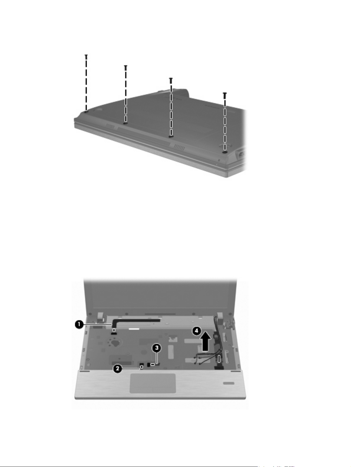
2. Remove the four PM2.5x5.0 screws along the front edge.
3. Position the computer right-side up with the front toward you, and open the display as far as
possible.
4. Release and disconnect the following zero insertion force (ZIF) connector cables from the system
board:
a. Power cable (1)
b. TouchPad cable (2)
c. Fingerprint reader cable (3)
5. Remove the WLAN cables (4) from the routing channel.
Component replacement procedures 57
Page 66

6. Remove the five PM2.5x5.0 screws that secure the keyboard to the base enclosure.
7. Lift the rear edge (1) of the top cover until it rests at an angle and you hear the locking tabs release.
8. Remove the top cover (2) by lifting first one side, then the other, until the top cover is released from
the enclosure.
Reverse this procedure to install the top cover.
58 Chapter 4 Removal and replacement procedures
Page 67

Display assembly
Description Spare part number
Display assembly (includes 2 WLAN antennas and cables and, on select computer models, 2 WWAN antennas and cables)
WXGA AntiGlare display assembly without webcam
●
WXGA AntiGlare display assembly with webcam
●
WXGA AntiGlare display assembly with webcam and WWAN
●
WXGA BrightView display assembly without webcam
●
WXGA BrightView display assembly with webcam
●
Display bezel
For use with displays with webcam
●
For use with displays without webcam
●
Webcam module 610835-001
Display panel
Display Hinge Kit
Display Hinge Kit (includes left and right display hinges)
●
Display cable
Display cable for use with displays with webcam (includes microphone and webcam connector)
●
Display cable for use with displays without webcam (includes microphone)
●
WLAN antennas and cables (included with display back cover)
610807-001
610808-001
610809-001
610810-001
610811-001
610814-001
610815-001
610817-001
610816-001
614742-001
WWAN antennas and cables (included with display back cover used with WWAN option)
Display back cover
For use with displays without WWAN
●
For use with displays with WWAN 610813-001
●
610812-001
Before removing the display assembly, follow these steps:
1. Shut down the computer. If you are unsure whether the computer is off or in Hibernation, turn the
computer on, and then shut it down through the operating system.
2. Disconnect all external devices connected to the computer.
3. Disconnect the power from the computer by first unplugging the power cord from the AC outlet and
then unplugging the AC adapter from the computer.
4. Remove the battery (see
Battery on page 40).
5. Remove the following components:
a. Switch cover (see
b. Keyboard (see
Switch cover on page 51)
Keyboard on page 53)
Component replacement procedures 59
Page 68

c. WWAN cables (see WWAN module on page 45)
d. WLAN cables (see
e. Top cover (see
WLAN module on page 42)
Top cover on page 56)
Remove the display assembly:
1. Disconnect the display cable (1) from the system board (2).
CAUTION: Support the display assembly when removing the following screws. Failure to support
the display assembly can result in damage to the display assembly and other computer
components.
2. Remove the four PM2.5×5.0 screws (1) that secure the display assembly to the base enclosure.
3. Lift the display assembly (2) straight up and remove it from the base enclosure.
60 Chapter 4 Removal and replacement procedures
Page 69

4. If it is necessary to replace the display bezel, display enclosure, or display hinges, remove the four
Mylar screw covers (1) and the four PM2.5×5.0 screws (2) that secure the display bezel to the
display assembly. The screw covers are available in the Rubber Kit, spare part number
610829-001.
5. Remove the bezel:
a. Flex the top (1) of the bezel from the inside edge until it disengages from the display back
cover.
b. Flex the inside edge of the left side and the right side (2) of the bezel until it disengages from
the display back cover.
c. Flex the bottom (3) of the bezel from the inside edge until it disengages from the display back
cover.
d. Remove the display bezel from the display back cover (4).
NOTE: While removing the display bezel, gently remove the double-sided tape that attaches the
bezel to the display panel.
Component replacement procedures 61
Page 70

6. If it is necessary to replace the webcam module, gently pull the webcam module away from the
double-sided tape on the display back cover (1), disconnect the webcam cable from the module
(2), and then remove the webcam.
NOTE: To replace the webcam module in the display enclosure, align the holes on the webcam
module with the pins on the display enclosure and press onto the double-sided tape.
7. If it is necessary to replace the display hinges, remove the display panel by removing the two
PM2.5×5.0 screws and the two PM2.5×3.0 screws (1) that secure the panel to the display back
cover.
8. Remove the display panel (2).
62 Chapter 4 Removal and replacement procedures
Page 71

9. Remove the four PM2.0×3.0 screws (1) that secure the display hinges to the display panel, and
then remove the display hinges (2). The left and right display hinges are available in the Display
Hinge Kit, spare part number 610817-001.
10. If it is necessary to replace the display/webcam cable, turn the display panel upside down and peel
back the tape that secures the display cable to the display panel (1), and then release the connector
locking bar (2).
11. Release the cable from the display panel connector (3).
NOTE: The display cable includes the microphone and, on select models, the webcam connector.
Component replacement procedures 63
Page 72

12. Gently pull the integrated microphone (1) from the clips at the top of the display back cover, remove
the display cable from the clips and routing channels (2) along the bottom of the display back cover,
and then remove the display cable (3).
13. If it is necessary to remove the wireless antennas and cables:
a. Detach the WLAN antennas and the WWAN antennas (1) from the adhesive on the back
cover, and then route the cables through the clips (2) that secure the antenna cables to the
display back cover.
b. Remove the wireless antennas and cables.
Reverse this procedure to reassemble and install the display assembly.
64 Chapter 4 Removal and replacement procedures
Page 73

Modem module
Description Spare part number
Modem module
NOTE: The modem module spare part kit does not include a modem module cable. The modem
module cable is included in the Cable Kit, 610806-001. See Cable Kit on page 27 for more Cable
Kit spare part information.
High-speed 56K modem 510100-011
Before removing the modem module, follow these steps:
1. Shut down the computer. If you are unsure whether the computer is off or in Hibernation, turn the
computer on, and then shut it down through the operating system.
2. Disconnect all external devices connected to the computer.
3. Disconnect the power from the computer by first unplugging the power cord from the AC outlet and
then unplugging the AC adapter from the computer.
4. Remove the battery (see
Battery on page 40).
5. Remove the following components:
a. Switch cover (see
b. Keyboard (see
Switch cover on page 51)
Keyboard on page 53)
c. Top cover (see
Top cover on page 56)
Remove the modem module:
1. Position the computer right-side up with the front toward you.
2. Disconnect the modem module cable (1).
3. Remove the two PM2.0×3.0 screws (2) that secure the modem module to the system board.
Component replacement procedures 65
Page 74

4. Lift the modem module (3) straight up to disconnect it from the system board.
5. Remove the modem module.
Reverse this procedure to install the modem module.
66 Chapter 4 Removal and replacement procedures
Page 75

Bluetooth module
Description Spare part number
Bluetooth module
NOTE: The Bluetooth module spare part kit does not include a Bluetooth module cable. The
Bluetooth module cable is included in the Cable Kit, spare part number 610806-001. See Cable Kit
on page 27) for more Cable Kit spare part information.
537921-001
Before removing the Bluetooth module, follow these steps:
1. Shut down the computer. If you are unsure whether the computer is off or in Hibernation, turn the
computer on, and then shut it down through the operating system.
2. Disconnect all external devices connected to the computer.
3. Disconnect the power from the computer by first unplugging the power cord from the AC outlet and
then unplugging the AC adapter from the computer.
4. Remove the battery (see
Battery on page 40).
5. Remove the following components:
a. Switch cover (see
b. Keyboard (see
c. Top cover (see
Switch cover on page 51)
Keyboard on page 53)
Top cover on page 56)
Remove the Bluetooth module:
1. Position the computer right-side up with the front toward you.
2. Remove the Bluetooth module from the base enclosure (1).
3. Disconnect the Bluetooth module cable (2), and then remove the Bluetooth module.
Component replacement procedures 67
Page 76

4. Remove the Bluetooth module cable (3) from the system board.
Reverse this procedure to install the Bluetooth module.
Audio board
Description Spare part number
Audio board (includes cable) 610805-001
Before removing the audio board, follow these steps:
1. Shut down the computer. If you are unsure whether the computer is off or in Hibernation, turn the
computer on, and then shut it down through the operating system.
2. Disconnect all external devices connected to the computer.
3. Disconnect the power from the computer by first unplugging the power cord from the AC outlet and
then unplugging the AC adapter from the computer.
4. Remove the battery (see
Battery on page 40).
5. Remove the following components:
a. Switch cover (see
b. Keyboard (see
c. Top cover (see
Switch cover on page 51)
Keyboard on page 53)
Top cover on page 56)
Remove the audio board:
1. Disconnect the audio board cable (1) from the system board.
2. Remove the PM 2.5x5.0 screw (2).
68 Chapter 4 Removal and replacement procedures
Page 77

3. Lift the audio board (3) straight up from the base enclosure.
Reverse this procedure to install the audio board.
Component replacement procedures 69
Page 78

RTC battery
Description Spare part number
RTC battery 599516-001
Before removing the RTC battery, follow these steps:
1. Shut down the computer. If you are unsure whether the computer is off or in Hibernation, turn the
computer on, and then shut it down through the operating system.
2. Disconnect all external devices connected to the computer.
3. Disconnect power from the computer by first unplugging the power cord from the AC outlet and
then unplugging the AC adapter from the computer.
4. Remove the battery (see
Battery on page 40).
5. Remove the following components:
a. Switch cover (see
b. Keyboard (see
c. Top cover (see
Switch cover on page 51)
Keyboard on page 53)
Top cover on page 56)
Remove the RTC battery:
1. Use a sharp, non-conductive tool to release the clip that secures the battery to the system board.
2. Lift the battery out of the computer.
To install the RTC battery, press it down into the socket until it is seated.
70 Chapter 4 Removal and replacement procedures
Page 79

System board
NOTE: The system board spare part kit includes replacement thermal material.
Description Spare part number
System board (includes replacement thermal material)
Includes Intel Arrandale I3-350M 2.26-GHz processor
●
Includes Intel Arrandale I5-540M 2.53-GHz processor
●
Includes Intel Arrandale I5-450M 2.4-GHz processor
●
Includes Intel Arrandale I5-520M 2.4-GHz processor
●
Includes Intel Celeron U3400 1.06-GHz processor 614536-001
●
610803-001
611373-001
614534-001
614535-001
Before removing the system board, follow these steps:
1. Shut down the computer. If you are unsure whether the computer is off or in Hibernation, turn the
computer on, and then shut it down through the operating system.
2. Disconnect all external devices connected to the computer.
3. Disconnect the power from the computer by first unplugging the power cord from the AC outlet and
then unplugging the AC adapter from the computer.
4. Remove the battery (see
Battery on page 40).
5. Remove the following components:
a. SIM (see
b. Switch cover (see
SIM on page 42)
Switch cover on page 51)
c. Keyboard (see
d. WWAN module (see
e. Bluetooth module and cable (see
f. WLAN module (see
g. Hard drive (see
h. Top cover (see
Keyboard on page 53)
WWAN module on page 45)
Bluetooth module on page 67)
WLAN module on page 42)
Hard drive on page 48)
Top cover on page 56)
When replacing the system board, be sure that the following components are removed from the defective
system board and installed on the replacement system board:
Memory module (see
●
WLAN module (see
●
WWAN module (see
●
Modem module (see
●
●
SIM (see
SIM on page 42)
Memory module on page 47)
WLAN module on page 42)
WWAN module on page 45)
Modem module on page 65)
Component replacement procedures 71
Page 80

Fan and heat sink (see
●
Fan and heat sink on page 75)
RTC battery (see
●
RTC battery on page 70)
Remove the system board:
1. Position the computer upside down with the rear toward you.
2. Disconnect the power connector cable from the system board.
3. Position the computer right-side up with the front toward you.
4. Disconnect the speaker cable (1) from the system board.
5. Disconnect the Bluetooth cable (2) from the system board.
6. Disconnect the audio board cable (3) from the system board.
72 Chapter 4 Removal and replacement procedures
Page 81

7. Disconnect the display panel cable (1) from the system board.
8. Disconnect the power button ZIF cable (2) from the system board.
9. Remove the two PM2.5×5.0 screws that secure the system board to the base enclosure.
10. Lift the right side of the system board from the base enclosure (1).
Component replacement procedures 73
Page 82

11. Lift the system board up and to the right to remove the system board (2).
Reverse this procedure to install the system board.
74 Chapter 4 Removal and replacement procedures
Page 83

Fan and heat sink
NOTE: The heat sink spare part kit includes replacement thermal material.
Description Spare part number
Fan 610824-001
Heat sink 610825-001
Before removing the heat sink, follow these steps:
1. Shut down the computer. If you are unsure whether the computer is off or in Hibernation, turn the
computer on, and then shut it down through the operating system.
2. Disconnect all external devices connected to the computer.
3. Disconnect the power from the computer by first unplugging the power cord from the AC outlet and
then unplugging the AC adapter from the computer.
4. Remove the battery (see
Battery on page 40).
5. Remove the following components:
a. SIM (see
b. Switch cover (see
c. Keyboard (see
d. WWAN module (see
e. Bluetooth module (see
f. WLAN module (see
g. Hard drive (see
h. Top cover (see
i. System board (see
SIM on page 42)
Switch cover on page 51)
Keyboard on page 53)
WWAN module on page 45)
Bluetooth module on page 67)
WLAN module on page 42)
Hard drive on page 48)
Top cover on page 56)
System board on page 71)
Remove the heat sink:
1. Position the system board upside down on a flat surface.
2. Disconnect the fan cable from the system board (1).
Component replacement procedures 75
Page 84

3. Loosen the two PM2.0×5.0 captive screws (2) from the system board, and then remove the fan
(3).
4. Following the sequence stamped into the heat sink, loosen the four PM2.5×10.0 captive screws
(1) that secure the heat sink to the processor.
5. Lift the heat sink off the processor (2).
NOTE: The thermal material must be thoroughly cleaned from the surfaces of the heat sink
components (1) and (2), and the system board components (3) and (4), each time the heat sink is
removed. Replacement thermal material is included with all heat sink and system board spare part
kits.
76 Chapter 4 Removal and replacement procedures
Page 85

Reverse this procedure to install the heat sink and fan.
Component replacement procedures 77
Page 86

Speakers
Description Spare part number
Speakers 610831-001
Before removing the speakers, follow these steps:
1. Shut down the computer. If you are unsure whether the computer is off or in Hibernation, turn the
2. Disconnect all external devices connected to the computer.
3. Disconnect the power from the computer by first unplugging the power cord from the AC outlet and
computer on, and then shut it down through the operating system.
then unplugging the AC adapter from the computer.
4. Remove the battery (see
Battery on page 40).
5. Remove the following components:
a. Switch cover (see
b. Keyboard (see
c. Top cover (see
d. System board (see
Switch cover on page 51)
Keyboard on page 53)
Top cover on page 56)
System board on page 71)
Remove the speakers:
1. Position the computer right-side up with the front toward you.
2. Remove the two PM2.0×3.0 screws (1) that secure the speakers to the base enclosure.
3. Remove the speakers from the computer (2).
Reverse this procedure to install the speakers.
78 Chapter 4 Removal and replacement procedures
Page 87

Security cable slot bracket
Before removing the security cable slot bracket, follow these steps:
1. Shut down the computer. If you are unsure whether the computer is off or in Hibernation, turn the
computer on, and then shut it down through the operating system.
2. Disconnect all external devices connected to the computer.
3. Disconnect the power from the computer by first unplugging the power cord from the AC outlet and
then unplugging the AC adapter from the computer.
4. Remove the battery (see
5. Remove the following components:
a. Switch cover (see
b. Keyboard (see
c. Top cover (see
d. System board (see
Remove the security cable slot bracket:
1. Position the computer right-side up with the right side toward you.
2. Remove the two PM2.0x5.0 screws (1) that secure the security cable slot bracket to the base
enclosure.
3. Lift the bracket (2) from the rear at an angle up and out.
Battery on page 40).
Switch cover on page 51)
Keyboard on page 53)
Top cover on page 56)
System board on page 71)
4. Disconnect the bracket from the power connector.
Reverse this procedure to install the security cable slot bracket.
Component replacement procedures 79
Page 88

Power connector cable
NOTE: The power connector cable is included in the Cable Kit on page 27, part number 610806-001.
Before removing the power connector cable, follow these steps:
1. Shut down the computer. If you are unsure whether the computer is off or in Hibernation, turn the
computer on, and then shut it down through the operating system.
2. Disconnect all external devices connected to the computer.
3. Disconnect the power from the computer by first unplugging the power cord from the AC outlet and
then unplugging the AC adapter from the computer.
4. Remove the battery (see
5. Remove the following components:
a. Switch cover (see
b. Keyboard (see
c. Top cover (see
d. System board (see
e. Security cable slot bracket (see
Remove the power connector cable.
1. Position the computer right-side up with the front toward you.
2. Remove the power connector cable (1) from the routing in the base enclosure.
3. Remove the power connector cable from the base enclosure (2).
Battery on page 40).
Switch cover on page 51)
Keyboard on page 53)
Top cover on page 56)
System board on page 71)
Security cable slot bracket on page 79)
Reverse this procedure to install the power connector cable.
80 Chapter 4 Removal and replacement procedures
Page 89

Modem module cable
NOTE: The modem module cable with RJ-11 connector is included in the Cable Kit on page 27, part
number 610806-001.
Before removing the modem module cable, follow these steps:
1. Shut down the computer. If you are unsure whether the computer is off or in Hibernation, turn the
computer on, and then shut it down through the operating system.
2. Disconnect all external devices connected to the computer.
3. Disconnect the power from the computer by first unplugging the power cord from the AC outlet and
then unplugging the AC adapter from the computer.
4. Remove the battery (see
5. Remove the following components:
a. Switch cover (see
b. Keyboard (see
c. Speakers (see
d. Hard drive (see
e. Display assembly (see
f. Top cover (see
g. System board (see
h. Security cable slotbracket (see
Remove the modem cable.
1. Position the computer right-side up with the front toward you.
2. Release the modem RJ-11 connector from the base enclosure clips (1).
Battery on page 40).
Switch cover on page 51)
Keyboard on page 53)
Speakers on page 78)
Hard drive on page 48)
Display assembly on page 59)
Top cover on page 56)
System board on page 71)
Security cable slot bracket on page 79)
Component replacement procedures 81
Page 90

3. Remove the modem cable (2) from the routing in the base enclosure.
Reverse this procedure to install the modem cable.
82 Chapter 4 Removal and replacement procedures
Page 91

5 Computer Setup
Computer Setup in Windows 7
Starting Computer Setup
Computer Setup is a preinstalled, ROM-based utility that can be used even when the operating system
is not working or will not load.
NOTE: Some of the Computer Setup menu items listed in this guide may not be supported by your
computer.
NOTE: An external keyboard or mouse connected to a USB port can be used with Computer Setup
only if USB legacy support is enabled.
To start Computer Setup, follow these steps:
1. Turn on or restart the computer, and then press esc while the “Press the ESC key for Startup Menu”
message is displayed at the bottom of the screen.
2. Press f10 to enter BIOS Setup.
Using Computer Setup
Navigating and selecting in Computer Setup
The information and settings in Computer Setup are accessed from the File, Security, Diagnostics, and
System Configuration menus.
To navigate and select in Computer Setup, follow these steps:
1. Turn on or restart the computer, and then press esc while the “Press the ESC key for Startup Menu”
message is displayed at the bottom of the screen.
To select a menu or a menu item, use the tab key and the keyboard arrow keys and then
●
press enter, or use a pointing device to click the item.
To scroll up and down, click the up arrow or the down arrow in the upper-right corner of the
●
screen, or use the up arrow key or the down arrow key.
To close open dialog boxes and return to the main Computer Setup screen, press esc, and
●
then follow the on-screen instructions.
Computer Setup in Windows 7 83
Page 92

NOTE: You can use either a pointing device (TouchPad, pointing stick, or USB mouse) or the
keyboard to navigate and make selections in Computer Setup.
2. Press f10 to enter BIOS Setup.
3. Select the File, Security, Diagnostics, or System Configuration menu.
To exit Computer Setup menus, choose one of the following methods:
To exit Computer Setup menus without saving your changes, click the Exit icon in the lower-left
●
corner of the screen, and then follow the on-screen instructions.
– or –
Use the tab key and the arrow keys to select File > Ignore Changes and Exit, and then press
enter.
– or –
To save your changes and exit Computer Setup menus, click the Save icon in the lower-left corner
●
of the screen, and then follow the on-screen instructions.
– or –
Use the tab key and the arrow keys to select File > Save Changes and Exit, and then press
enter.
Your changes go into effect when the computer restarts.
Restoring factory settings in Computer Setup
NOTE: Restoring defaults will not change the hard drive mode.
To return all settings in Computer Setup to the values that were set at the factory, follow these steps:
1. Turn on or restart the computer, and then press esc while the “Press the ESC key for Startup Menu”
message is displayed at the bottom of the screen.
2. Press f10 to enter BIOS Setup.
3. Use a pointing device or the arrow keys to select File > Restore Defaults.
4. Follow the on-screen instructions.
5. To save your changes and exit, click the Save icon in the lower-left corner of the screen, and then
follow the on-screen instructions.
– or –
Use the arrow keys to select File > Save Changes and Exit, and then press enter.
Your changes go into effect when the computer restarts.
NOTE: Your password settings and security settings are not changed when you restore the factory
settings.
Computer Setup menus
The menu tables in this section provide an overview of Computer Setup options.
84 Chapter 5 Computer Setup
Page 93

NOTE: Some of the Computer Setup menu items listed in this chapter may not be supported by your
computer.
File menu
Select To do this
System Information
Set System Date and Time Set or change the date and time on the computer.
System Diagnostic Display the following information:
View identification information for the computer and the
●
batteries in the system.
View specification information for the processor, memory
●
size, system ROM, video revision, keyboard controller
version, and wireless identification numbers.
System Information
●
Identification information for the computer and the
◦
batteries in the system.
Specification information for the processor, cache
◦
and memory size, system ROM, video revision, and
keyboard controller version.
Start-up Test: verifies the system components needed for
●
starting the computer.
Run-In Test: runs a comprehensive check on system
●
memory.
Hard Disk Test: runs a comprehensive self-test on any
●
hard drive in the system.
Memory Test: runs a comprehensive test on any memory
●
installed in the computer.
Restore Defaults Replace the configuration settings in Computer Setup with the
Reset BIOS security to factory default Resets password to the factory default in case of a forgotten
Ignore Changes and Exit Cancel any changes entered during the current session. Then
Save Changes and Exit Save any changes entered during the current session. Then
Security menu
NOTE: Some of the menu items listed in this section may not be supported by your computer.
Battery Test: runs a comprehensive test on any batteries
●
installed in the computer.
Error Log: displays a log file if any errors have occurred.
●
original factory settings. (Hard drive mode, password settings,
and security settings are not changed when you restore the
factory settings.)
password.
exit and restart the computer.
exit and restart the computer. Your changes go into effect
when the computer restarts.
Computer Setup in Windows 7 85
Page 94

Select To do this
Setup BIOS Administrator Password Set up a BIOS administrator password.
User Management (requires a BIOS administrator password)
Password Policy (requires a BIOS administrator password) Revise password policy criteria.
HP SpareKey Enable/disable HP SpareKey (enabled by default).
Always Prompt for HP SpareKey Enrollment Enable/disable HP SpareKey enrollment (enabled by default).
Anti Theft (select models only) Enable/disable anti-theft protection.
Fingerprint Reset on Reboot (If Present) Reset/clear the fingerprint reader ownership (disabled by
Allow reset of HP ProtectTools security keys Enable/disable reset of HP ProtectTools security keys.
Change Password Enter, change, or delete a BIOS administrator password.
HP SpareKey Enrollment Enroll or reset HP SpareKey, which is a set of security
DriveLock Passwords
Create a new BIOS user account.
●
View a list of HP ProtectTools users.
●
default).
questions and answers used if you forget your password.
Enable/disable DriveLock on any computer hard drive
●
(enabled by default).
Change a DriveLock user password or master password.
●
NOTE: DriveLock settings are accessible only when you
enter Computer Setup by turning on (not restarting) the
computer.
Automatic DriveLock Enable/disable Automatic DriveLock support.
Disk Sanitizer Run Disk Sanitizer to destroy all existing data on the primary
System IDs Enter a user-defined computer asset tracking number and
System Configuration menu
NOTE: Some of the listed System Configuration options may not be supported by your computer.
Select To do this
Language Change the Computer Setup language.
hard drive.
CAUTION: If you run Disk Sanitizer, the data on the selected
drive is destroyed permanently.
ownership tag.
86 Chapter 5 Computer Setup
Page 95

Select To do this
Boot Options
Device Configurations
Set a Startup Menu delay (in seconds).
●
Set the MultiBoot Express Boot Popup delay in seconds.
●
Enable/disable Custom Logo (disabled by default).
●
Enable/disable Display Diagnostic URL (enabled by
●
default).
Enable/disable CD-ROM boot (enabled by default).
●
Enable/disable SD Card boot (enabled by default).
●
Enable/disable floppy boot (enabled by default).
●
Enable/disable PXE Internal NIC boot (enabled by
●
default).
Enable/disable Unified Extensible Firmware Interface
●
(UEFI) Boot Mode (disabled by default).
Set the Express Boot Popup delay in seconds.
●
Set the boot order.
●
Enable/disable USB legacy support (enabled by default).
●
When enabled, USB legacy support allows the following:
Use of a USB keyboard in Computer Setup even
◦
when a Windows® operating system is not running.
Startup from bootable USB devices, including a hard
◦
drive, diskette drive, or external optical drive
connected by a USB port to the computer.
Enable/disable fan always on while connected to an AC
●
outlet (enabled by default).
Enable/disable Data Execution Prevention. When
●
enabled, the processor can disable some virus code
execution, which helps to improve computer security.
Enable/disable LAN Power Save (select models only).
●
When enabled, saves power by turning off the LAN when
not in use (enabled by default).
SATA (Serial Advanced Technology Attachment) device
●
mode. The following options are available:
AHCI (Advanced Host Controller Interface)
◦
IDE (Integrated Drive Electronics)
◦
Computer Setup in Windows 7 87
Page 96

Select To do this
NOTE: Availability of the options above varies by
computer model.
Enable/disable HP DayStarter (enabled by default).
●
Enable/disable HP QuickLook (enabled by default).
●
Enable/disable Preboot Authentication on HP QuickLook
●
Boot (disabled by default).
Enable/disable Virtualization Technology (select models
●
only; disabled by default).
Enable/disable HP QuickWeb (enabled by default).
●
Enable/disable HP QuickWeb write protect (disabled by
●
default).
Enable/disable Multi Core CPU (enabled by default).
●
Enable/disable Intel® HT Technology (enabled by
●
default).
Enable/disable wake on USB (enabled by default).
●
Enable/disable Unified Extensible Firmware Interface
●
(UEFI) mode (disabled by default).
Turn the Numlock state at boot on or off.
●
88 Chapter 5 Computer Setup
Page 97

Select To do this
Built-In Device Options
Enable/disable the wireless button state (enabled by
●
default).
Enable/disable the embedded WLAN device (enabled by
●
default).
Enable/disable embedded WWAN device radio (select
●
models only; enabled by default).
Enable/disable embedded Bluetooth® device radio
●
(enabled by default).
Enable/disable the Network Interface Controller (LAN)
●
(enabled by default).
Enable/disable LAN/WLAN switching (disabled by
●
default).
Set the wake on LAN state. Options include the
●
following:
Disabled
◦
Boot to Network (set by default)
◦
Follow Boot Order
◦
Enable/disable the fingerprint device (enabled by
●
default).
Enable/disable a modem device (enabled by default).
●
Enable the ambient light sensor (enabled by default).
●
Enable/disable the Notebook MultiBay device (enabled by
●
default).
Enable/disable the integrated camera (select models only;
●
enabled by default).
Enable/disable the power monitor circuit (enabled by
●
default).
Enable/disable the audio device (enabled by default).
●
Enable/disable optical disc drive (enabled by default).
●
Enable/disable internal microphone (enabled by default).
●
Enable/disable the internal speakers (enabled by default).
●
Port Options (all are enabled by default) NOTE: All port options are enabled by default.
Enable/disable the Smart Card slot.
●
Enable/disable the flash media reader.
●
Enable/disable the USB port.
●
CAUTION: Disabling the USB port also disables
MultiBay devices on the advanced port replicator.
Enable/disable the 1394 port.
●
Enable/disable the eSATA port.
●
Computer Setup in Windows 7 89
Page 98

Select To do this
Set Security Level Change, view, or hide security levels for all BIOS menu items.
Restore Security Defaults Restore the default security settings.
90 Chapter 5 Computer Setup
Page 99

Computer Setup in Windows Vista and Windows XP
Starting Computer Setup
Computer Setup is a preinstalled, ROM-based utility that can be used even when the operating system
is not working or will not load.
NOTE: Some of the Computer Setup menu items listed in this guide may not be supported by your
computer.
NOTE: An external keyboard or mouse connected to a USB port can be used with Computer Setup
only if USB legacy support is enabled.
To start Computer Setup, follow these steps:
1. Turn on or restart the computer, and then press esc while the “Press the ESC key for Startup Menu”
message is displayed at the bottom of the screen.
2. Press f10 to enter BIOS Setup.
Using Computer Setup
Navigating and selecting in Computer Setup
The information and settings in Computer Setup are accessed from the File, Security, Diagnostics, and
System Configuration menus.
To navigate and select in Computer Setup, follow these steps:
1. Turn on or restart the computer, and then press esc while the “Press the ESC key for Startup Menu”
message is displayed at the bottom of the screen.
To select a menu or a menu item, use the tab key and the keyboard arrow keys and then
●
press enter, or use a pointing device to click the item.
To scroll up and down, click the up arrow or the down arrow in the upper-right corner of the
●
screen, or use the up arrow key or the down arrow key.
To close open dialog boxes and return to the main Computer Setup screen, press esc, and
●
then follow the on-screen instructions.
NOTE: You can use either a pointing device (TouchPad, pointing stick, or USB mouse) or the
keyboard to navigate and make selections in Computer Setup.
2. Press f10 to enter BIOS Setup.
3. Select the File, Security, Diagnostics, or System Configuration menu.
Computer Setup in Windows Vista and Windows XP 91
Page 100

To exit Computer Setup menus, choose one of the following methods:
To exit Computer Setup menus without saving your changes, click the Exit icon in the lower-left
●
corner of the screen, and then follow the on-screen instructions.
– or –
Use the tab key and the arrow keys to select File > Ignore Changes and Exit, and then press
enter.
– or –
To save your changes and exit Computer Setup menus, click the Save icon in the lower-left corner
●
of the screen, and then follow the on-screen instructions.
– or –
Use the tab key and the arrow keys to select File > Save Changes and Exit, and then press
enter.
Your changes go into effect when the computer restarts.
Restoring factory settings in Computer Setup
NOTE: Restoring defaults will not change the hard drive mode.
To return all settings in Computer Setup to the values that were set at the factory, follow these steps:
1. Turn on or restart the computer, and then press esc while the “Press the ESC key for Startup Menu”
message is displayed at the bottom of the screen.
2. Press f10 to enter BIOS Setup.
3. Use a pointing device or the arrow keys to select File > Restore Defaults.
4. Follow the on-screen instructions.
5. To save your changes and exit, click the Save icon in the lower-left corner of the screen, and then
follow the on-screen instructions.
– or –
Use the arrow keys to select File > Save Changes and Exit, and then press enter.
Your changes go into effect when the computer restarts.
NOTE: Your password settings and security settings are not changed when you restore the factory
settings.
92 Chapter 5 Computer Setup
 Loading...