

Page 1

HP ProBook 4325s Notebook PC
HP ProBook 4326s Notebook PC
HP ProBook 4425s Notebook PC
Maintenance and Service Guide
SUMMARY
This guide is a troubleshooting reference used for maintaining and servicing the computer. It provides
comprehensive information on identifying computer features, components, and spare parts;
troubleshooting computer problems; and performing computer disassembly procedures.
Page 2

© Copyright 2010 Hewlett-Packard
Development Company, L.P.
AMD and ATI are trademarks of Advanced
Micro Devices, Inc. Bluetooth is a
trademark owned by its proprietor and used
by Hewlett-Packard Company under
license. Microsoft, Windows, and Windows
Vista are U.S. registered trademarks of
Microsoft Corporation. SD Logo is a
trademark of its proprietor.
The information contained herein is subject
to change without notice. The only
warranties for HP products and services are
set forth in the express warranty statements
accompanying such products and services.
Nothing herein should be construed as
constituting an additional warranty. HP shall
not be liable for technical or editorial errors
or omissions contained herein.
Second Edition: October 2011
First Edition: May 2010
Document Part Number: 602200-002
Page 3

Safety warning notice
WARNING! To reduce the possibility of heat-related injuries or of overheating the computer, do not
place the computer directly on your lap or obstruct the computer air vents. Use the computer only on
a hard, flat surface. Do not allow another hard surface, such as an adjoining optional printer, or a soft
surface, such as pillows or rugs or clothing, to block airflow. Also, do not allow the AC adapter to
contact the skin or a soft surface, such as pillows or rugs or clothing, during operation. The computer
and the AC adapter comply with the user-accessible surface temperature limits defined by the
International Standard for Safety of Information Technology Equipment (IEC 60950).
iii
Page 4

iv Safety warning notice
Page 5

Table of contents
1 Product description ........................................................................................................................................ 1
2 External component identification ................................................................................................................ 9
Identifying hardware ............................................................................................................................. 9
Top components ................................................................................................................................. 10
TouchPad .......................................................................................................................... 10
Lights ................................................................................................................................. 11
Buttons, speakers, switches, and fingerprint reader (select models only) ......................... 12
Keys ................................................................................................................................... 13
Front components .............................................................................................................................. 14
Right-side components ....................................................................................................................... 15
Left-side components ......................................................................................................................... 16
Bottom components ........................................................................................................................... 17
Display ................................................................................................................................................ 18
Wireless antennas (select models only) ............................................................................................. 19
Additional hardware components ....................................................................................................... 20
3 Illustrated parts catalog ............................................................................................................................... 21
Serial number label location ............................................................................................................... 21
Computer major components ............................................................................................................. 22
Display assembly components ........................................................................................................... 28
Plastics Kit .......................................................................................................................................... 30
Cable kit ............................................................................................................................................. 31
Mass storage devices ......................................................................................................................... 32
Miscellaneous parts ............................................................................................................................ 33
Sequential part number listing ............................................................................................................ 34
4 Removal and replacement procedures ....................................................................................................... 39
Preliminary replacement requirements ............................................................................................... 39
Tools required .................................................................................................................... 39
Service considerations ....................................................................................................... 39
v
Page 6

Plastic parts ....................................................................................................... 39
Cables and connectors ..................................................................................... 40
Drive handling ................................................................................................... 40
Grounding guidelines ......................................................................................................... 41
Electrostatic discharge damage ........................................................................ 41
Packaging and transporting guidelines ............................................. 42
Workstation guidelines ..................................................................... 42
Equipment guidelines ....................................................................... 43
Component replacement procedures ................................................................................................. 44
Serial number label ............................................................................................................ 44
Computer feet .................................................................................................................... 44
Battery ............................................................................................................................... 45
SIM .................................................................................................................................... 46
Switch cover ...................................................................................................................... 47
Keyboard ........................................................................................................................... 49
Memory module ................................................................................................................. 51
Optical drive ....................................................................................................................... 53
Power button board ........................................................................................................... 55
Speakers ............................................................................................................................ 56
Palm rest ............................................................................................................................ 58
Hard drive .......................................................................................................................... 61
RTC battery ....................................................................................................................... 64
WLAN module .................................................................................................................... 65
Bluetooth module ............................................................................................................... 68
Heat sink and fan ............................................................................................................... 70
Processor ........................................................................................................................... 74
Power connector cable ...................................................................................................... 76
Display assembly ............................................................................................................... 77
Top cover ........................................................................................................................... 85
Modem module .................................................................................................................. 87
System board ..................................................................................................................... 89
USB connector board ........................................................................................................ 91
Modem module cable ........................................................................................................ 93
5 Computer Setup ............................................................................................................................................ 95
Computer Setup in Windows 7 ........................................................................................................... 95
Starting Computer Setup ................................................................................................... 95
Using Computer Setup ...................................................................................................... 95
Navigating and selecting in Computer Setup .................................................... 95
Restoring factory settings in Computer Setup ................................................... 96
Computer Setup menus ..................................................................................................... 97
vi
Page 7

File menu .......................................................................................................... 97
Security menu ................................................................................................... 98
System Configuration menu .............................................................................. 99
Computer Setup in Windows Vista and Windows XP ...................................................................... 101
Starting Computer Setup ................................................................................................. 101
Using Computer Setup .................................................................................................... 101
Navigating and selecting in Computer Setup .................................................. 101
Restoring factory settings in Computer Setup ................................................. 102
Computer Setup menus ................................................................................................... 103
File menu ........................................................................................................ 103
Security menu ................................................................................................. 104
Diagnostics menu ............................................................................................ 105
System Configuration menu ............................................................................ 106
Computer Setup in Linux .................................................................................................................. 108
Starting Computer Setup ................................................................................................. 108
Using Computer Setup .................................................................................................... 108
Navigating and selecting in Computer Setup .................................................. 108
Restoring factory settings in Computer Setup ................................................. 109
Computer Setup menus ................................................................................................... 109
File menu ........................................................................................................ 109
Security menu ................................................................................................. 110
Diagnostics menu ............................................................................................ 111
System Configuration menu ............................................................................ 112
6 Specifications .............................................................................................................................................. 114
Computer specifications ................................................................................................................... 114
33.8-cm (13.3-in) display specifications ........................................................................................... 115
35.6-cm (14.0-in) display specifications ........................................................................................... 116
Hard drive specifications .................................................................................................................. 117
DVD ROM Drive specifications ........................................................................................................ 118
DVD±RW SuperMulti Double-Layer Drive with LightScribe specifications ....................................... 119
Blu-ray ROM with LightScribe DVD±R/RW SuperMulti DL Drive specifications .............................. 120
System resource specifications ........................................................................................................ 121
7 Backup and recovery .................................................................................................................................. 122
Windows 7 backup and recovery ..................................................................................................... 122
Backing up ....................................................................................................................... 122
Recovering ....................................................................................................................... 124
Backup and recovery in Windows Vista ........................................................................................... 125
Overview .......................................................................................................................... 125
Backing up your information ............................................................................................ 125
vii
Page 8

Performing a recovery ..................................................................................................... 126
Using the Windows recovery tools ................................................................................... 126
Using f11 .......................................................................................................................... 127
Using a Windows Vista operating system DVD (purchased separately) ......................... 128
Backup and recovery in Windows XP .............................................................................................. 129
Overview .......................................................................................................................... 129
Backing up your information ............................................................................................ 129
Performing a recovery ..................................................................................................... 130
Recovering your information ........................................................................... 130
Recovering the operating system and programs ............................................ 130
Linux backup and recovery .............................................................................................................. 131
8 Connector pin assignments ....................................................................................................................... 132
Audio-in (microphone) ...................................................................................................................... 132
Audio-out (headphone) ..................................................................................................................... 133
External monitor ............................................................................................................................... 134
HDMI ................................................................................................................................................ 135
RJ-11 (modem) ................................................................................................................................ 136
RJ-45 (network) ................................................................................................................................ 137
Universal Serial Bus ......................................................................................................................... 138
eSATA/USB ...................................................................................................................................... 139
9 Power cord set requirements .................................................................................................................... 140
Requirements for all countries and regions ...................................................................................... 140
Requirements for specific countries and regions ............................................................................. 141
10 Recycling ................................................................................................................................................... 142
Battery .............................................................................................................................................. 142
Display .............................................................................................................................................. 142
Index ................................................................................................................................................................. 148
viii
Page 9

1 Product description
Category Description HP
ProBook
4325s
UMA Discrete UMA
Product Name HP ProBook 4325s Notebook PC
NOTE: Discrete not for use in the People's Republic of
China.
HP ProBook 4326s Notebook PC
NOTE: For use in the People's Republic of China.
HP ProBook 4425s Notebook PC √
Processors AMD
AMD Phenom II Quad-Core Mobile Processors
● Phenom II P940 1.7 GHz, 2-MB L2 cache (25W) √√√
AMD Phenom II Triple-Core Mobile Processors
● Phenom II P860, 2.0 GHz, 1.5-MB L2 cache (25W) √√√
Phenom II P960 1.8 GHz, 2-MB L2 cache (25W) √√√
●
Phenom II P920 1.6 GHz, 2-MB L2 cache (25W) √√√
●
√
√
HP
ProBook
4326s
HP
ProBook
4425s
AMD Phenom II Dual-Core Mobile Processors
AMD Turion II Dual-Core Mobile Processors
● Turion II P560 2.5 GHz, 2-MB L2 cache (25W) √√√
AMD Athlon II Dual-Core Mobile Processors
Phenom II P840, 1.9 GHz, 1.5-MB L2 cache (25W) √√√
●
Phenom II P820, 1.8 GHz, 1.5-MB L2 cache (25W) √√√
●
Phenom II P650, 2.6 GHz, 2-MB L2 cache (25W) √√√
●
Turion II P540 2.4 GHz, 2-MB L2 cache (25W) √√√
●
Turion II P520 2.3 GHz, 2-MB L2 cache (25W) √√√
●
Athlon II P360 2.3 GHz, 1-MB L2 cache (25W) √√√
●
Athlon II P340 2.2 GHz, 1-MB L2 cache (25W) √√√
●
1
Page 10

Category Description HP
ProBook
4325s
UMA Discrete UMA
HP
ProBook
4326s
HP
ProBook
4425s
● Athlon II P320 2.1 GHz, 1-MB L2 cache (25W)
AMD V-Series Single-Core Processors
● V140 2.3 GHz, 512-KB L2 cache (25W) √√√
Chipsets AMD √√√
● RS880M √ √
Graphics ATI Mobility Radeon™ HD 4250
ATI Mobility Radeon™ HD 530v
ATI Mobility Radeon HD 6370 √
ATI Mobility Radeon HD 5470 √
V160 2.4 GHz, 512-KB L2 cache (25W) √√√
●
V120 2.2 GHz, 512-KB L2 cache (25W) √√√
●
RS880MD √
●
SB820 √√√
●
Universal Memory Architecture (UMA) graphics subsystem
integrated with shared video memory (dynamically allocated)
AMD discrete graphics ATI-M93S3-LP with Hypermemory
support; 512-MB DDR3, 800 MHz
√√√
√ √
√
Panels All display panel assemblies support privacy filter √√√
LED backlight √√√
● 33.8-cm (13.3-in) HD BrightView √√
● 33.8-cm (13.3-in) HD (1366×768 resolution) red √√
● 33.8-cm (13.3-in) HD AG with webcam, red √√
● 35.6-cm (14.0-in) HD BrightView with webcam √
● 35.6-cm (14.0-in) HD BrightView, red √
33.8-cm (13.3-in) HD (1366×768 resolution) √√
●
33.8-cm (13.3-in) HD BrightView with webcam √√
●
33.8-cm (13.3-in) HD AG with webcam √√
●
33.8-cm (13.3-in) HD BrightView, red √√
●
33.8-cm (13.3-in) HD BrightView with webcam, red √√
●
35.6-cm (14.0-in) HD (1366×768 resolution) √
●
35.6-cm (14.0-in) HD BrightView √
●
35.6-cm (14.0-in) HD AG with webcam √
●
35.6-cm (14.0-in) HD (1366x768), red √
●
2 Chapter 1 Product description
Page 11

Category Description HP
ProBook
4325s
UMA Discrete UMA
HP
ProBook
4326s
HP
ProBook
4425s
● 35.6-cm (14.0-in) HD BrightView with webcam, red
Memory 2 customer-accessible/upgradable SODIMM memory module
Supports dual-channel memory √√√
PC3-10600, 1333-MHz, DDR3 √√√
Supports the following configuration:
35.6-cm (14.0-in) HD AG with webcam, red √
●
slots
● 8192-MB total system memory (4096-MB × 2, dual-
channel)
4096-MB total system memory (4096-MB × 1)
●
● 4096-MB total system memory (2048-MB × 2, dual
channel)
3072-MB total system memory (2048-MB + 1024-MB,
●
dual channel)
2048-MB total system memory (2048-MB × 1)
●
2048-MB total system memory (1024-MB × 2, dual
●
channel)
1024-MB total system memory (1024-MB × 1)
●
√
√√√
√√√
Hard drives Supports 9.5-mm, 6.35-cm (2.50-in) hard drives √√√
Customer-accessible √√√
Serial ATA √√√
Supports the following drives:
640-GB, 5400-rpm
●
500-GB, 7200-rpm
●
● 320-GB, 7200-rpm
250-GB, 7200-rpm
●
HP 3D DriveGuard (not available on Linux) √√√
Optical drives Fixed √√√
12.7-mm (0.50-in) tray load √√√
Supports option of no optical drive √√√
Supports the following drives:
Blu-ray ROM with LightScribe DVD±R/RW SuperMulti DL
●
Drive
NOTE: Not available with UMA base model and Window XP.
√√√
√√√
3
Page 12

Category Description HP
ProBook
4325s
UMA Discrete UMA
HP
ProBook
4326s
HP
ProBook
4425s
● DVD±RW SuperMulti Double-Layer Drive with
LightScribe
● DVD ROM Drive √√√
Diskette drive Supports external USB diskette drive only √√√
Audio/Visual HD audio - IDT 92HD80 √√√
Integrated microphone √√√
Two stereo speakers √√√
Integrated 2.0-megapixel webcam (fixed focus) √√√
Headphone and microphone jacks √√√
Modem High-speed 56k modem √√√
High-speed 56k modem for use in Brazil √√
Modem cable not included √√√
Supports no modem option √√√
Ethernet Realtek 10/100/1000 Ethernet network interface card (NIC) √√√
S3/S4/S5 wake on LAN (AC only mode) √√√
S3/S4/S5 wake on LAN (AC only mode) √√√
Ethernet cable not included √√√
√√√
Wireless Integrated WLAN options by way of wireless module:
Support for the following WLAN formats:
Broadcom 802.11b/g
●
Broadcom 802.11b/g/n 1x1
●
● Atheros 802.11b/g/n 1x1
● Realtek 802.11b/g/n 1x1
2 WLAN antennas built into display assembly √√√
Support for no-WLAN option √√√
Integrated personal area network (PAN) options by way of Bluetooth® module:
Support for no-WPAN option √√√
Broadcom Bluetooth 2.1 + EDR √√√
Integrated WWAN options by way of WWAN module:
WWAN module UNDP with 2 antennas (not available with
Two five-band WWAN antennas built into display assembly √
Linux)
√√√
√
4 Chapter 1 Product description
Page 13

Category Description HP
ProBook
4325s
UMA Discrete UMA
HP
ProBook
4326s
HP
ProBook
4425s
Subscriber identity module (SIM) security (customer-
External media
cards
Media Card Reader supporting Memory Stick (MS), Memory
Ports Audio-in (stereo microphone) √√√
Audio-out (stereo headphone) √√√
RJ-11 (modem) √√√
RJ-45 (Ethernet, includes link and activity lights) √√√
USB 2.0 (3) √√√
Combo eSATA/USB 2.0 (1) √√√
HDMI √√√
VGA (Dsub 15-pin) supporting 1600 × 1200 external resolution
Multi-pin AC power √√√
Keyboard and
pointing devices
accessible in battery bay)
One ExpressCard slot (34 mm) √√√
Stick Pro (MSP), Secure Digital (SD) Memory Card, Secure
Digital High Capacity (SDHC) Memory Card, MultiMediaCard
(MMC), and xD-Picture Card formats
at 75-GHz (hot plug/unplug with auto-detect)
33.8-cm (13.3-in) keyboard with TouchPad √√
√
√√√
√√√
35.6-cm (14.0-in) keyboard with TouchPad √
TouchPad only, with 2 TouchPad buttons and vertical scrolling
Power
requirements
90-W AC adapter with localized cable plug support (3-wire
9-cell, 93-Wh Li-ion battery √√ √
6-cell, 47-Wh Li-ion battery √√ √
Security Supports Kensington security lock √√ √
Operating
system
Windows 7 Professional 32 (with Windows XP Professional
Windows 7 Professional 32 with MS Basics (Japan only) √√
Windows 7 Home Premium 32 with MS Basics (Japan only) √√
Windows Vista Business 32 with MS Basics (Japan only) √√
(taps enabled as default)
65-W AC adapter with localized cable plug support (3-wire
plug with ground pin)
plug with ground pin)
Preinstalled:
NOTE: Windows Vista® includes SP2 and Windows® XP
Pro includes SP3 (Ver 2)
images) with MS Basics (Japan only)
√√√
√ √
√
√√
5
Page 14

Category Description HP
ProBook
4325s
UMA Discrete UMA
HP
ProBook
4326s
HP
ProBook
4425s
Windows Vista Home Basic 32 with MS Basics (Japan only)
FreeDOS √√√
RedFlag Linux (People's Republic of China only) √√
SUSE Linux (SLED11) √√√
Preinstalled with Office:
Windows 7 Starter with Office 2007 Ready (excludes Japan) √√√
Windows 7 Starter with Office 2007 Ready - EDGI (available
for Argentina, Brazil - English, Brazil, Latin America, Latin
America - English, Russia, India, Asia Pacific, Thailand)
Windows 7 Home Basic 32 with Office 2007 Ready (excludes
Japan)
Windows 7 Home Basic with Office 2007 Ready - EDGI
(available for Argentina, Brazil - English, Brazil, Latin America,
Latin America - English, Russia, People's Republic of China,
India, Asia Pacific, Thailand)
Windows 7 Home Premium 32 with Office 2007 Ready
(excludes Japan)
Windows 7 Home Premium with Office 2007 Ready - EDGI
(available for Argentina, Brazil - English, Brazil, Latin America,
Latin America - English, Russia, People's Republic of China,
Hong Kong, India, Asia Pacific, Thailand)
√√
√√√
√√√
√√√
√√√
√√√
Windows 7 Home Premium 32 with Office 2007 Personal
(Japan only)
Windows 7 Home Premium 32 with Office 2007 Personal with
PowerPoint (Japan only)
Windows 7 Home Premium 32 with Office 2007 Professional
(Japan only)
Windows 7 Professional 32 with Office 2007 Ready (excludes
Japan)
Windows 7 Professional 32 with Office 2007 Ready - EDGI
(available for Argentina, Brazil - English, Brazil, Latin America,
Latin America - English, Russia, People's Republic of China,
Hong Kong, India, Asia Pacific, Thailand)
Windows 7 Professional 32 with Office 2007 Personal (Japan
only)
Windows 7 Professional 32 with Office 2007 Personal with
PowerPoint (Japan only)
Windows 7 Professional 32 with Office Professional (Japan
only)
Windows 7 Professional (with Windows XP Professional
images) with Office 2007 Ready (excludes Japan)
√√
√√
√√
√√√
√√√
√√
√√
√√
√√√
6 Chapter 1 Product description
Page 15

Category Description HP
ProBook
4325s
UMA Discrete UMA
HP
ProBook
4326s
HP
ProBook
4425s
Windows 7 Professional (with Windows XP Professional
images) with Office 2007 Ready - EDGI (available for
Argentina, Brazil - English, Brazil, Latin America, Latin
America - English, Russia, People's Republic of China, Hong
Kong, India, Asia Pacific, Thailand)
Windows 7 Professional (with Windows XP Professional
images) with Office 2007 Personal (Japan only)
Windows 7 Professional (with Windows XP Professional
images) with Office 2007 Personal with PowerPoint (Japan
only)
Windows 7 Professional (with Windows XP Professional
images) with Office 2007 Professional (Japan only)
Windows Vista Home Basic 32 with Office 2007 Ready
(excludes Japan)
Windows Vista Home Basic 32 with Office 2007 Personal
(Japan only)
Windows Vista Home Basic 32 with Office 2007 Personal with
PowerPoint (Japan only)
Windows Vista Home Basic 32 with Office 2007 Professional
(Japan only)
Windows Vista Business 32 with Office 2007 Ready (excludes
Japan)
√√√
√√
√√
√√
√√√
√√√
√√√
√√√
√√√
Windows Vista Business 32 with Office 2007 Personal (Japan
only)
Windows Vista Business 32 with Office 2007 Personal with
PowerPoint (Japan only)
Windows Vista Business 32 with Office Professional (Japan
only)
Restore media:
Windows 7 Professional 64 √√√
Windows 7 Professional 32 √√√
Windows 7 Home Premium 32 √√√
Windows 7 Home Basic 32 √√√
Windows 7 Starter √√√
Windows Vista Business 32 √√√
Windows Vista Home Basic 32 √√√
Windows XP Professional √√√
Microsoft Office Ready DVD √√√
DRDVD Windows 7 Home Premium/Windows 7 Professional √√√
√√√
√√√
√√√
7
Page 16

Category Description HP
ProBook
4325s
UMA Discrete UMA
HP
ProBook
4326s
HP
ProBook
4425s
DRDVD Windows 7 Starter/Windows 7 Home Basic
DRDVD Windows XP Professional √√√
DRDVD Windows Vista √√√
Red Flag Linux (in the People's Republic of China only) √√√
SUSE Linux √√√
Certified: Microsoft® WHQL √√√
Web Support:
Windows 7 Professional 64 √√√
Windows Vista Business 64 √√√
Serviceability End-user replaceable parts:
AC adapter √√√
Battery (system) √√√
Bluetooth module √√√
Keyboard √√√
Speaker assembly √√√
Hard drive √√√
√√√
Memory module √√√
Optical drive √√√
WLAN module √√√
WWAN module √ √
WWAN SIM √ √
8 Chapter 1 Product description
Page 17

2 External component identification
Identifying hardware
Components included with the computer may vary by region and model. The illustrations in this
chapter identify the standard features on most computer models.
NOTE: Your computer may look slightly different from the illustrations in this section.
Use the following instructions to see a list of hardware installed in the computer.
In Windows® 7:
▲ Select Start > Control Panel > System and Security > Device Manager.
You can also add hardware or modify device configurations using Device Manager.
NOTE: Windows includes the User Account Control feature to improve the security of your
computer. You may be prompted for your permission or password for tasks such as installing
software, running utilities, or changing Windows settings. Refer to Help and Support for more
information.
In Windows Vista®:
1. Select Start > Computer > System Properties.
2. In the left pane, click Device Manager.
You can also add hardware or modify device configurations using Device Manager.
NOTE: Windows includes the User Account Control feature to improve the security of your
computer. You may be prompted for your permission or password for tasks such as installing
software, running utilities, or changing Windows settings. Refer to Help and Support for more
information.
In Windows XP:
1. Select Start > My Computer.
2. In the left pane of the System Tasks window, select View system information.
3. Select Hardware tab > Device Manager.
You can also add hardware or modify device configurations using Device Manager.
Identifying hardware 9
Page 18
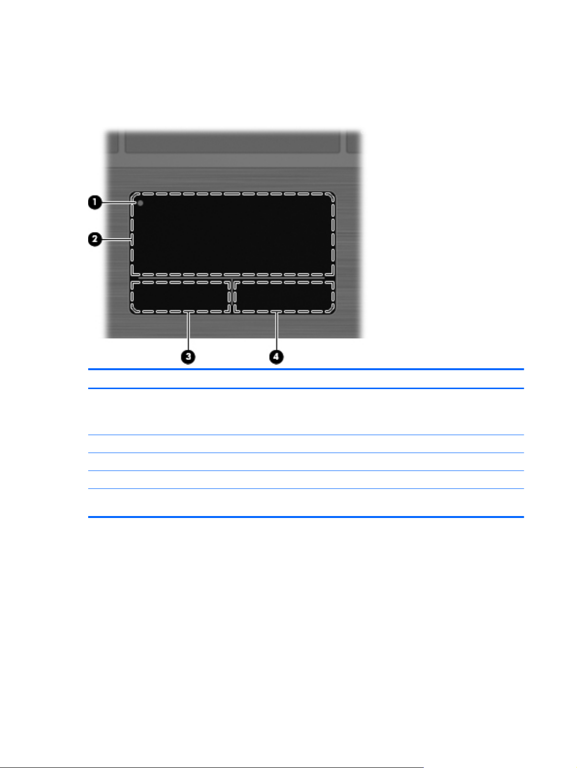
Top components
TouchPad
Component Description
(1) TouchPad off indicator To turn the TouchPad zone on and off, quickly double-tap the
(2) TouchPad zone* Moves the pointer and selects or activates items on the screen.
(3) Left TouchPad button* Functions like the left button on an external mouse.
(4) Right TouchPad button* Functions like the right button on an external mouse.
*This table describes factory settings. To view or change pointing device preferences, select Start > Control Panel >
Printers and Other Hardware > Mouse.
TouchPad off indicator.
NOTE: When the TouchPad zone is active, the light is off.
10 Chapter 2 External component identification
Page 19
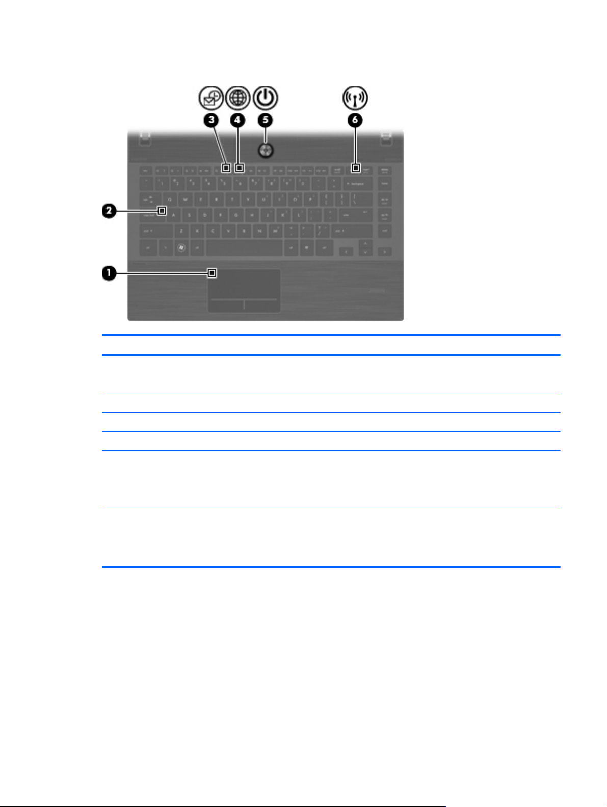
Lights
Component Description
(1) TouchPad off indicator
(2) Caps lock light On: Caps lock is on.
(3) HP QuickLook light Blinking: QuickLook is being opened or closed.
(4) HP QuickWeb light Blinking: The Web browser is being opened or closed.
(5) Power light
(6) Wireless light
Amber: The TouchPad is off.
●
● Off: The TouchPad is on.
On: The computer is on.
●
● Blinking: The computer is in Standby.
● Off: The computer is off or in Hibernation.
White: An integrated wireless device, such as a wireless
●
local area network (WLAN) device and/or a Bluetooth®
device, is on.
Amber: All wireless devices are off.
●
Top components 11
Page 20

Buttons, speakers, switches, and fingerprint reader (select models only)
NOTE: Your computer may look slightly different from the illustration in this section.
Component Description
(1) Speakers (2) Produce sound.
(2) Internal display switch Turns off the display if the display is closed while the power is on.
(3) Power button ● When the computer is off, press the button to turn on the
(4) Fingerprint reader (select models only) Allows a fingerprint logon to Windows, instead of a password
computer.
● When the computer is on, press the button to shut down the
computer.
When the computer is in Standby, press the button briefly to
●
exit Standby.
● When the computer is in Hibernation, press the button
briefly to exit Hibernation.
If the computer has stopped responding and Windows®
shutdown procedures are ineffective, press and hold the power
button for at least 5 seconds to turn off the computer.
To learn more about your power settings and how to change
them, select Start > Control Panel > Performance and
Maintenance > Power Options.
logon.
12 Chapter 2 External component identification
Page 21

Keys
Component Description
(1) esc key Displays system information when pressed in combination with
(2) fn key Executes frequently used system functions when pressed in
(3) Windows logo key Displays the Windows Start menu.
(4) Windows applications key Displays a shortcut menu for items beneath the cursor.
(5) Embedded numeric keypad keys Can be used like the keys on an external numeric keypad when
(6) Function keys Execute frequently used system functions when pressed in
the fn key.
combination with a function key or the esc key.
pressed in combination with the fn and num lk keys.
combination with the fn key.
Top components 13
Page 22

Front components
Component Description
(1) Drive light ● Blinking white: The hard drive or optical drive is being
(2) Media Card Reader Supports the following optional digital card formats:
(3) Audio-out (headphone) jack Produces sound when connected to optional powered stereo
(4) Audio-in (microphone) jack Connects an optional computer headset microphone, stereo
accessed.
Amber: HP 3D DriveGuard has temporarily parked the hard
●
drive.
● Memory Stick
Memory Stick Duo (adapter required)
●
Memory Stick Pro (adapter required)
●
● MultiMediaCard (MMC)
Secure Digital (SD) Memory Card
●
xD-Picture Card (XD)
●
● xD-Picture Card (XD) Type H
xD-Picture Card (XD) Type M
●
speakers, headphones, ear buds, a headset, or television audio.
NOTE: When a device is connected to the headphone jack, the
computer speakers are disabled.
array microphone, or monaural microphone.
14 Chapter 2 External component identification
Page 23
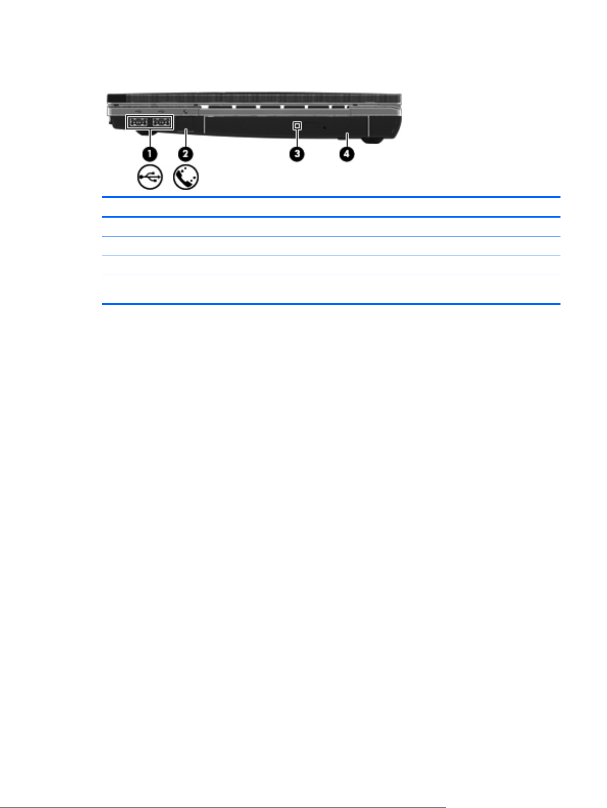
Right-side components
Component Description
(1) USB ports (2) Connect optional USB devices.
(2) RJ-11 (modem) jack (select models only) Connects a modem cable.
(3) Optical drive light (select models only) Blinking: The optical drive is being accessed.
(4) Optical drive (select models only) Reads optical discs and, on select models, also writes to optical
discs.
Right-side components 15
Page 24

Left-side components
Component Description
(1) Security cable slot Attaches an optional security cable to the computer.
(2) Power connector Connects an AC adapter.
NOTE: The security cable is designed to act as a deterrent, but
it may not prevent the computer from being mishandled or stolen.
(3) AC adapter light
(4) Vent Enables airflow to cool internal components.
(5) External monitor port Connects an external VGA monitor or projector.
(6) RJ-45 (network) jack Connects a network cable.
(7) HDMI port Connects an optional HDMI device.
(8) Combo eSATA/USB port Connects an optional USB device or high-performance eSATA
(9) USB port Connects optional USB device.
(10) ExpressCard slot Supports optional ExpressCards.
On: The computer is connected to external power and the
●
battery is charging.
Off: The computer is not connected to external power.
●
NOTE: The computer fan starts up automatically to cool internal
components and prevent overheating. It is normal for the internal
fan to cycle on and off during routine operation.
components, such as an eSATA external hard drive.
16 Chapter 2 External component identification
Page 25

Bottom components
Component Description
(1) Battery release latches (2) Release the battery from the battery bay.
(2) Battery bay Holds the battery.
(3) SIM slot (select models only) Contains a wireless subscriber identity module (SIM). The SIM
slot is located inside the battery bay.
Bottom components 17
Page 26

Display
NOTE: Your computer may look slightly different from the illustration in this section.
Component Description
(1) Internal display switch Turns off the display if the display is closed while the power is on.
(2) Internal microphone Records sound.
(3) Webcam light (select models only) On: The webcam is in use.
(4) Webcam (select models only) Records video and captures still photographs.
18 Chapter 2 External component identification
Page 27
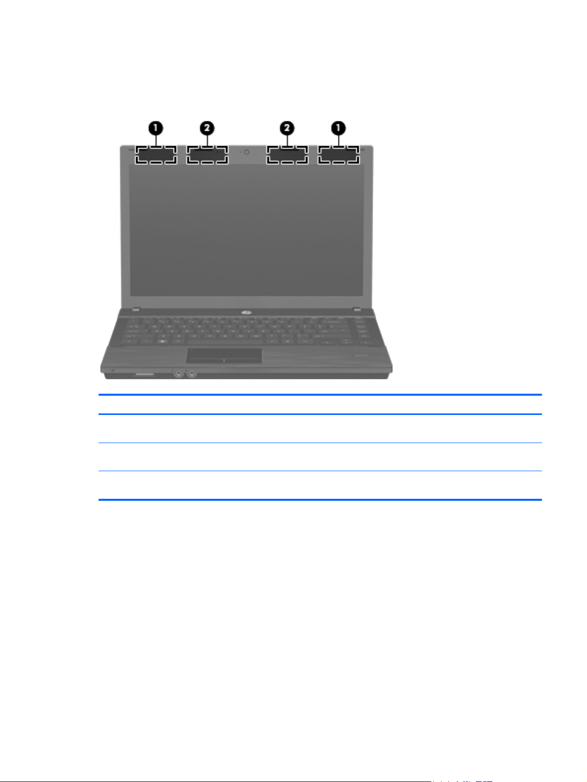
Wireless antennas (select models only)
The antennas send and receive signals from one or more wireless devices. These antennas are not
visible from the outside of the computer.
Component Description
(1) WWAN antennas (2)* Send and receive wireless signals to communicate with wireless
(2) WLAN antennas (2)* Send and receive wireless signals to communicate with wireless
*The antennas are not visible from the outside of the computer. For optimal transmission, keep the areas immediately
around the antennas free from obstructions.
wide area networks (WWANs).
local area networks (WLANs).
To see wireless regulatory notices, refer to the section of the Regulatory, Safety and Environmental
Notices that applies to your country or region. These notices are located in Help and Support.
Wireless antennas (select models only) 19
Page 28

Additional hardware components
Component Description
(1) Power cord* Connects an AC adapter to an AC outlet.
(2) Battery* Powers the computer when the computer is not plugged into an
external power source.
(3) AC adapter Converts AC power to DC power.
*Batteries and power cords vary in appearance by country or region.
20 Chapter 2 External component identification
Page 29

3 Illustrated parts catalog
Serial number label location
When ordering parts or requesting information, the serial number label, located on the bottom of the
computer, provides important information that you may need when contacting technical support.
(1) Product name (4) Warranty period
(2) Serial number (5) Model description (select models)
(3) Product number
Serial number label location 21
Page 30

Computer major components
22 Chapter 3 Illustrated parts catalog
Page 31

Item Description Spare part number
(1) Display assembly (includes 2 WLAN antennas and cables and, on select computer models, 2 WWAN antennas
and cables)
NOTE: WWAN is available only on select models with 33.8-cm 13.3-in displays.
For use in black models:
● 33.8-cm (13.3-in) HD BrightView 599554-001
● 33.8-cm (13.3-in) HD (1366x768 resolution) , red 608736-001
● 35.6-cm (14.0-in) HD BrightView with webcam 608131-001
For use in red models:
● 33.8-cm (13.3-in) HD BrightView 608737-001
● 35.6-cm (14.0-in) HD (1366x768 resolution) 608740-001
33.8-cm (13.3-in) HD (1366x768 resolution) 599553-001
●
33.8-cm (13.3-in) HD BrightView with webcam 608127-001
●
33.8-cm (13.3-in) HD AG with webcam 608128-001
●
35.6-cm (14.0-in) HD (1366x768 resolution) 599559-001
●
35.6-cm (14.0-in) HD BrightView 599560-001
●
35.6-cm (14.0-in) HD AG with webcam 608132-001
●
33.8-cm (13.3-in) HD BrightView with webcam 608730-001
●
33.8-cm (13.3-in) HD AG with webcam 608731-001
●
35.6-cm (14.0-in) HD BrightView 608741-001
●
35.6-cm (14.0-in) HD BrightView with webcam 608734-001
●
● 35.6-cm (14.0-in) HD AG with webcam 608735-001
For use in champagne models:
● 33.8-cm (13.3-in) HD (1366x768 resolution) with a webcam 625718-001
(2) Switch cover
For use in black models:
● For with 33.8-cm
For use in red models:
● For with 33.8-cm (13.3-in) displays 607652-001
For use in champagne models:
33.8-cm (13.3-in) HD (1366x768 resolution) 625690-001
●
33.8-cm (13.3-in) HD BrightView 625692-001
●
33.8-cm (13.3-in) HD BrightView with a webcam 625719-001
●
For with 35.6-cm (14.0-in) displays 599568-001
●
(13.3-in) displays 599567-001
For with 35.6-cm (14.0-in) displays 607653-001
●
Computer major components 23
Page 32

Item Description Spare part number
(3) Power button board (with cable) 599517-001
(4) Keyboard
In computer models with 33.8-cm (13.3-in) displays:
● For use in Japan 599572-291
● For use in Thailand 599572-281
In computer models with 35.6-cm (14.0-in) displays:
● For use in Brazil 599573-201
● For use in the United States 599573-001
(5) Palm rest (includes TouchPad)
For with 33.8-cm (13.3-in) displays 625716-001
●
For use in Greece 599572-DJ1
●
For use in Korea 599572-AD1
●
For use in Taiwan 599572-AB1
●
For use in the United States 599572-001
●
For use in Canada (French) 599573-121
●
For use in Latin America 599573-161
●
For use in black models:
● For use with fingerprint reader and 33.8-cm (13.3-in) displays 599549-001
● For use with 35.6-cm (14.0-in) displays 599552-001
For use in red models:
● For use with 33.8-cm (13.3-in) displays 607650-001
For use in champagne models:
(6) Top heat shield/bracket (included with top cover)
(7) Fan 599544-001
(8) Processor heat sink
For use with 33.8-cm (13.3-in) displays 599551-001
●
For use with fingerprint reader and 35.6-cm (14.0-in) displays 599550-001
●
For use with fingerprint reader and 33.8-cm (13.3-in) displays 607648-001
●
For use with fingerprint reader and 35.6-cm (14.0-in) displays 607649-001
●
For use with 35.6-cm (14.0-in) displays 607651-001
●
For use with fingerprint reader and 33.8-cm (13.3-in) displays 625712-001
●
For use with
●
33.8-cm (13.3-in) displays 625714-001
For use with discrete graphics subsystems 615575-001
For use with Unified Memory Architecture (UMA) graphics subsystems 615576-001
24 Chapter 3 Illustrated parts catalog
Page 33

Item Description Spare part number
(9) Memory module (PC3-10600, 1333-MHz, DDR3, shared)
4096-MB 599092-001
2048-MB 598856-002
(10) Bluetooth module cable (included in
(11) Bluetooth module (without cable) 537921-001
(12) Modem module
NOTE: The modem module spare part kit does not include a modem module cable. The
modem module cable is included in the Cable kit. See
Cable Kit spare part information.
(13) WLAN module
Atheros AR 9285 802.11b/g/n 605560-005
Broadcom BCM94313HMG2L 802.11b/g/n 593836-001
Broadcom 4312G 802.11b/g WiFi Adapter
For use in Canada, the Cayman Islands, Guam, Puerto Rico, the United States, and the
U.S. Virgin Islands
For use in Afghanistan, Albania, Algeria, Andorra, Angola, Antigua and Barbuda, Argentina,
Armenia, Aruba, Australia, Austria, Azerbaijan, the Bahamas, Bahrain, Bangladesh,
Barbados, Belarus, Belgium, Belize, Benin, Bermuda, Bhutan, Bolivia, Bosnia and
Herzegovina, Botswana, Brazil, the British Virgin Islands, Brunei, Bulgaria, Burkina Faso,
Burundi, Cambodia, Cameroon, Cape Verde, the Central African Republic, Chad, Colombia,
Comoros, the Congo, Costa Rica, Croatia, Cyprus, the Czech Republic, Denmark, Djibouti,
Dominica, the Dominican Republic, East Timor, Ecuador, Egypt, El Salvador, Equatorial
Guinea, Eritrea, Estonia, Ethiopia, Fiji, Finland, France, French Guiana, Gabon, Gambia,
Georgia, Germany, Ghana, Gibraltar, Greece, Grenada, Guadeloupe, Guatemala, Guinea,
Guinea-Bissau, Guyana, Haiti, Honduras, Hong Kong, Hungary, Iceland, India, Indonesia,
Ireland, Israel, Italy, the Ivory Coast, Jamaica, Japan, Jordan, Kazakhstan, Kenya, Kiribati,
Kuwait, Kyrgyzstan, Laos, Latvia, Lebanon, Lesotho, Liberia, Liechtenstein, Lithuania,
Luxembourg, Macedonia, Madagascar, Malawi, Malaysia, the Maldives, Mali, Malta, the
Marshall Islands, Martinique, Mauritania, Mauritius, Mexico, Micronesia, Monaco, Mongolia,
Montenegro, Morocco, Mozambique, Namibia, Nauru, Nepal, the Nether Antilles, the
Netherlands, New Zealand, Nicaragua, Niger, Nigeria, Norway, Oman, Pakistan, Palau,
Panama, Papua New Guinea, Paraguay, the People's Republic of China, Peru, the
Philippines, Poland, Portugal, Qatar, the Republic of Moldova, Romania, Russia, Rwanda,
Samoa, San Marino, Sao Tome and Principe, Saudi Arabia, Senegal, Serbia, the
Seychelles, Sierra Leone, Singapore, Slovakia, Slovenia, the Solomon Islands, Somalia,
South Africa, South Korea, Spain, Sri Lanka, St. Kitts and Nevis, St. Lucia, St. Vincent and
the Grenadines, Suriname, Swaziland, Sweden, Switzerland, Syria, Taiwan, Tajikistan,
Tanzania, Thailand, Togo, Tonga, Trinidad and Tobago, Tunisia, Turkey, Turkmenistan,
Tuvalu, Uganda, Ukraine, the United Arab Emirates, the United Kingdom, Uruguay,
Uzbekistan, Vanuatu, Venezuela, Vietnam, Yemen, Zaire, Zambia, and Zimbabwe
Cable kit on page 31, part number 599525-001)
628824-001
Cable kit on page 31 for more
504593-003
504593-004
Realtek RTL8191SE 802.11b/g/n 1x1 WiFi Adapter 593533-001
Ralink RT3090BC4 802.11b/g/n 1x1 WiFi and Bluetooth 2.1+EDR Combo Adapter
(Bluetooth 3.0+high-speed ready)
Broadcom 4313/2070 802.11b/g/n (1x1) and Bluetooth high-speed Half Mini Card 600370-001
(14) WWAN module, Qualcomm EV-DO HSPA 531993-001
(15) RTC battery 599516-001
602992-001
Computer major components 25
Page 34

Item Description Spare part number
(16) Top cover
For use with 33.8-cm (13.3-in) displays 599569-001
For use with 35.6-cm (14.0-in) displays 599570-001
(17) Processor (includes replacement thermal material)
AMD Phenom II processors:
● P960, 1.8Ghz 634689-001
● P860, 2.0Ghz 634688-001
● P650, 2.6Ghz 634687-001
AMD Turion II processors:
● P540, 2.4GHz 616347-001
AMD Athlon II processors:
● P360, 2.3GHz 636635-001
AMD Sempron processor:
P940, 1.7Ghz 616336-001
●
P920, 1.6Ghz 594170-001
●
P840, 1.9Ghz 616335-001
●
P820, 1.8Ghz 594167-001
●
P560, 2.5GHz 634691-001
●
P520, 2.3GHz 594173-001
●
P340, 2.2GHz 616343-001
●
P320, 2.1GHz 594165-001
●
N120, 2.2GHz 594171-001
●
AMD single-core processors:
● V160. 2.4GHz 636634-001
(18) System board (includes replacement thermal material)
For use in all countries and regions except for Russia and the People's Republic of China
V140. 2.3GHz 616333-001
●
For use with ATI Mobility Radeon HD 530v discrete graphics and 33.8-cm (13.3-in)
●
displays
For use with ATI Mobility Radeon HD 5470 discrete graphics and 33.8-cm (13.3-in)
●
displays
For use with ATI Mobility Radeon HD 6370 discrete graphics and 33.8-cm (13.3-in)
●
displays
For use with UMA graphics subsystem and 33.8-cm (13.3-in) displays 607655-001
●
For use with UMA graphics subsystem and 35.6-cm (14.0-in) displays 607656-001
●
26 Chapter 3 Illustrated parts catalog
607654-001
628489-001
628619-001
Page 35

Item Description Spare part number
For use in only Russia and the People's Republic of China:
(19) Power connector board with cable 599517-001
(20) RJ11 (modem) cable (see Cable kit)
(21) Speakers
● For use with 33.8-cm (13.3-in) displays 599566-001
(22) USB connector board and cable 599524-001
(23) ExpressCard slot bezel (included in Plastics kit, see
(24) Base enclosure
For use in computer models with 33.8-cm (13.3-in) displays 599514-001
For use in computer models with 35.6-cm (14.0-in) displays 599515-001
(25) Battery
For use with ATI Mobility Radeon HD 530v discrete graphics and 33.8-cm (13.3-in)
●
displays
For use with ATI Mobility Radeon HD 5470 discrete graphics and 33.8-cm (13.3-in)
●
displays
For use with ATI Mobility Radeon HD 6370 discrete graphics and 33.8-cm (13.3-in)
●
displays
For use with UMA graphics subsystem and 33.8-cm (13.3-in) displays 614963-001
●
For use with 35.6-cm (14.0-in) displays 605559-001
●
Plastics Kit on page 30)
614962-001
628490-001
628620-001
9-cell, 93-Wh (2.8Ah) Li-ion 593573-001
6-cell, 47-Wh (2.2Ah) Li-ion 593572-001
(26) Hard drive (includes hard drive bracket)
750-GB, 5400-rpm 634250-001
640-GB, 5400-rpm 631160-001
500-GB, 7200-rpm 634919-001
320-GB, 7200-rpm 603783-001
250-GB, 7200-rpm 599541-001
Hard Drive Hardware Kit (not illustrated) 630889-001
(27) SIM (provided by your wireless vendor for use with WWAN option)
(28) Optical drive (includes bezel)
Blu-ray Disc ROM Drive with SuperMulti DVD±R/RW Double-Layer 599538-001
DVD±RW SuperMulti Double-Layer Drive with LightScribe 599540-001
DVD ROM Drive 599539-001
Battery Latch Kit (not illustrated) 657098-001
Optical drive connector for use in 35.6-cm (14.0-in) models (not illustrated) 632213-001
Computer major components 27
Page 36

Display assembly components
Item Description Spare part number
(1) Display bezel
● For 33.8-cm (13.3-in) displays with webcam 599530-001
● For 35.6-cm (14.0-in) displays without webcam 599533-001
For 35.6-cm (14.0-in) displays with webcam 599531-001
●
For 33.8-cm (13.3-in) displays without webcam 599532-001
●
28 Chapter 3 Illustrated parts catalog
Page 37

Item Description Spare part number
(2) Webcam module 617666-001
(3) Display panel (also included with display assembly; see
on page 22)
● 35.6-cm (14.0-in), HD, BrightView 592144-001
(4) Display hinge kit
(5) Display cable (includes microphone and, on select models, webcam connector)
● Display cable for 33.8-cm (13.3-in) displays without webcam 605557-001
(6) WLAN antennas and cables (included with back cover)
(7) WWAN antennas and cables (included with back covers used with WWAN option)
33.8-cm (13.3-in), HD, BrightView 588160-001
●
33.8-cm (13.3-in), HD, Anti-Glare 623175-001
●
35.6-cm (14.0-in), HD, Anti-Glare 623176-001
●
Display hinge and panel bracket (left and right) for 33.8-cm (13.3-in) displays 599536-001
●
Display hinge and panel bracket (left and right) for 35.6-cm (14.0-in) displays 599537-001
●
Display cable for 33.8-cm (13.3-in) displays with webcam 599534-001
●
Display cable for 35.6-cm (14.0-in) displays with webcam 605558-001
●
Display cable for 35.6-cm (14.0-in) displays without webcam 599535-001
●
Display cable for 33.8-cm (13.3-in) displays with webcam without WWAN 616070-001
●
Computer major components
(8) Display back cover
For use on black models:
● For 35.6-cm (14.0-in) displays with webcam and without WWAN 605556-001
For use on red models:
● For 33.8-cm (13.3-in) displays without WWAN 607643-001
● For 35.6-cm (14.0-in) displays with webcam and without WWAN 607646-001
For use on champagne models:
● For 33.8-cm (13.3-in) displays with webcam and without WWAN 625699-001
For 33.8-cm (13.3-in) displays without WWAN 599526-001
●
For 35.6-cm (14.0-in) displays without WWAN 599527-001
●
For 33.8-cm (13.3-in) displays with webcam and without WWAN 607094-001
●
For 33.8-cm (13.3-in) displays with webcam and without WWAN 607644-001
●
For 33.8-cm (14.0-in) displays without WWAN 607645-001
●
For 33.8-cm (13.3-in) displays without WWAN 625698-001
●
Display assembly components 29
Page 38

Plastics Kit
Item Description Spare part number
Plastics Kit: 599563-001
(1) ExpressCard slot bezel
(2) Optical drive blank (used with no ODD option)
RJ11 (modem) connector blank (not illustrated, used with No-Modem option)
30 Chapter 3 Illustrated parts catalog
Page 39

Cable kit
Item Description Spare part number
Cable kit: 599525-001
(1) Power cable
(2) Bluetooth cable
(3) RJ-11 (modem) jack cable
Cable kit 31
Page 40

Mass storage devices
Item Description Spare part number
(1) Hard drive (includes bracket)
750-GB, 5400-rpm 634250-001
640-GB, 5400-rpm 631160-001
500-GB, 7200-rpm 634919-001
320-GB, 7200-rpm 603783-001
250-GB, 7200-rpm 599541-001
Hard Drive Hardware Kit 630889-001
(2) Optical drive (includes bezel)
Blu-ray Disc ROM Drive with SuperMulti DVD ±R/RW Double-Layer 599538-001
DVD±RW SuperMulti Double-Layer Drive with LightScribe 599540-001
DVD-ROM Drive 599539-001
32 Chapter 3 Illustrated parts catalog
Page 41

Miscellaneous parts
Description Spare part number
AC adapters
65-W, 3-pin Smart AC adapter
For use in all countries and regions except India 609939-001
●
For use in India 609948-001
●
90-W Slimline AC adapter
For use in all countries and regions except India 609940-001
●
For use in India 609947-001
●
Power cords (AC power, 3-pin, black, 1.83 m)
For use in Argentina 490371-D01
●
For use in Austria 490371-011
●
● For use in Brazil 490371-202
For use in India 490371-D61
●
For use in Japan 490371-291
●
● For use in North America 490371-001
For use in the People's Republic of China 490371-AA1
●
For use in South Korea 490371-AD1
●
● For use in Taiwan 490371-AB1
For use in the United Kingdom and Singapore 490371-031
●
Rubber kit (includes display bumpers, display screw covers, base enclosure feet, and display
hinge bumpers)
Screw kit, includes:
● T8 slotted-torx M2.5x6.5
● T8 slotted-torx M2.5x5.0
● T8 slotted-torx M2.5x3.0
Phillips P1 M2.5x5.0
●
Phillips P1 M2.5x3.0
●
Phillips P1 M2.0x3.0
●
Phillips P0 M2.0x2.5
●
● Phillips M3.0x3.5
599564-001
599565-001
Miscellaneous parts 33
Page 42

Sequential part number listing
Spare part
number
490371-001 Power cord (AC power, 3-pin, black, 1.83 m), for use in North America
490371-011 Power cord (AC power, 3-pin, black, 1.83 m), for use in Austria
490371-031 Power cord (AC power, 3-pin, black, 1.83 m), for use in the United Kingdom and Singapore
490371-202 Power cord (AC power, 3-pin, black, 1.83 m), for use in Brazil
490371-291 Power cord (AC power, 3-pin, black, 1.83 m), for use in Japan
490371-AA1 Power cord (AC power, 3-pin, black, 1.83 m), for use in the People's Republic of China
490371-AB1 Power cord (AC power, 3-pin, black, 1.83 m), for use in Taiwan
490371-AD1 Power cord (AC power, 3-pin, black, 1.83 m), for use in South Korea
490371-D01 Power cord (AC power, 3-pin, black, 1.83 m), for use in Argentina
490371-D61 Power cord (AC power, 3-pin, black, 1.83 m), for use in India
504593-003 Broadcom 4312G 802.11b/g WiFi Adapter for use in Canada, the Cayman Islands, Guam, Puerto Rico,
504593-004 Broadcom 4312G 802.11b/g WiFi Adapter for use in Afghanistan, Albania, Algeria, Andorra, Angola,
Description
the United States, and the U.S. Virgin Islands
Antigua and Barbuda, Argentina, Armenia, Aruba, Australia, Austria, Azerbaijan, the Bahamas, Bahrain,
Bangladesh, Barbados, Belarus, Belgium, Belize, Benin, Bermuda, Bhutan, Bolivia, Bosnia and
Herzegovina, Botswana, Brazil, the British Virgin Islands, Brunei, Bulgaria, Burkina Faso, Burundi,
Cambodia, Cameroon, Cape Verde, the Central African Republic, Chad, Colombia, Comoros, the Congo,
Costa Rica, Croatia, Cyprus, the Czech Republic, Denmark, Djibouti, Dominica, the Dominican Republic,
East Timor, Ecuador, Egypt, El Salvador, Equatorial Guinea, Eritrea, Estonia, Ethiopia, Fiji, Finland,
France, French Guiana, Gabon, Gambia, Georgia, Germany, Ghana, Gibraltar, Greece, Grenada,
Guadeloupe, Guatemala, Guinea, Guinea-Bissau, Guyana, Haiti, Honduras, Hong Kong, Hungary,
Iceland, India, Indonesia, Ireland, Israel, Italy, the Ivory Coast, Jamaica, Japan, Jordan, Kazakhstan,
Kenya, Kiribati, Kuwait, Kyrgyzstan, Laos, Latvia, Lebanon, Lesotho, Liberia, Liechtenstein, Lithuania,
Luxembourg, Macedonia, Madagascar, Malawi, Malaysia, the Maldives, Mali, Malta, the Marshall Islands,
Martinique, Mauritania, Mauritius, Mexico, Micronesia, Monaco, Mongolia, Montenegro, Morocco,
Mozambique, Namibia, Nauru, Nepal, the Nether Antilles, the Netherlands, New Zealand, Nicaragua,
Niger, Nigeria, Norway, Oman, Pakistan, Palau, Panama, Papua New Guinea, Paraguay, the People's
Republic of China, Peru, the Philippines, Poland, Portugal, Qatar, the Republic of Moldova, Romania,
Russia, Rwanda, Samoa, San Marino, Sao Tome and Principe, Saudi Arabia, Senegal, Serbia, the
Seychelles, Sierra Leone, Singapore, Slovakia, Slovenia, the Solomon Islands, Somalia, South Africa,
South Korea, Spain, Sri Lanka, St. Kitts and Nevis, St. Lucia, St. Vincent and the Grenadines, Suriname,
Swaziland, Sweden, Switzerland, Syria, Taiwan, Tajikistan, Tanzania, Thailand, Togo, Tonga, Trinidad
and Tobago, Tunisia, Turkey, Turkmenistan, Tuvalu, Uganda, Ukraine, the United Arab Emirates, the
United Kingdom, Uruguay, Uzbekistan, Vanuatu, Venezuela, Vietnam, Yemen, Zaire, Zambia, and
Zimbabwe
531993-001 WWAN module, Qualcomm EV-DO HSPA
537921-001 Bluetooth module (without cable)
588160-001 Display panel, 33.8-cm (13.3-in), HD, BrightView
592144-001 Display panel, 35.6-cm (14.0-in), HD, BrightView
593533-001 Realtek RTL8191SE 802.11b/g/n 1x1 WiFi Adapter
593572-001 Battery, 6-cell, 47-Wh (2.2Ah) Li-ion
593573-001 Battery, 9-cell, 93-Wh (2.8Ah) Li-ion
593836-001 Broadcom BCM94313HMG2L 802.11b/g/n
34 Chapter 3 Illustrated parts catalog
Page 43

Spare part
number
594165-001 Athlon II P320 processor, 2.1GHz
594167-001 Phenom II P820 processor, 1.8Ghz
594170-001 Phenom II P920 processor, 1.6Ghz
594171-001 Sempron N120 processor, 2.2GHz
594173-001 Turion II P520 processor, 2.3GHz
598856-002 Memory module (PC3-10600 shared), 2048-MB
599092-001 Memory module (PC3-10600 shared), 4096-MB
599514-001 Base enclosure, for use with 33.8-cm (13.3-in) models
599515-001 Base enclosure, for use in 35.6-cm (14.0-in) models
599516-001 RTC battery
599517-001 Power connector board with cable
599524-001 USB board and cable
599525-001 Cable kit
599526-001 Display back cover for 33.8-cm (13.3-in) displays without WWAN
599527-001 Display back cover for 35.6-cm (14.0-in) displays without WWAN
Description
599530-001 Display bezel for 33.8-cm (13.3-in) models with webcam
599531-001 Display bezel for 35.6-cm (14.0-in) models with webcam
599532-001 Display bezel for 33.8-cm (13.3-in) models without webcam
599533-001 Display bezel for 35.6-cm (14.0-in) models without webcam
599534-001 Display cable for 33.8-cm (13.3-in) displays with webcam
599535-001 Display cable for 35.6-cm (14.0-in) displays without webcam
599536-001 Display hinge and bracket (left and right) for 33.8-cm (13.3-in) models
599537-001 Display hinge and bracket (left and right) for 35.6-cm (14.0-in) models
599538-001 Blu-ray Disc ROM Drive with SuperMulti DVD ±R/RW Double-Layer
599539-001 DVD ROM Drive
599540-001 DVD±RW SuperMulti Double-Layer Drive with LightScribe
599541-001 Hard drive, 250-GB, 7200-rpm
599544-001 Fan
599549-001 Palm rest with Touchpad and fingerprint reader for use with 33.8-cm (13.3-in) displays
599550-001 Palm rest with Touchpad and fingerprint reader for use with 35.6-cm (14.0-in) displays
599551-001 Palm rest with Touchpad for use with 33.8-cm (13.3-in) displays, red
599552-001 Palm rest with Touchpad for use with 35.6-cm (14.0-in) displays
599553-001 Display assembly, 33.8-cm (13.3-in) HD (1366x768 resolution)
599554-001 Display assembly, 33.8-cm (13.3-in) HD BrightView
Sequential part number listing 35
Page 44

Spare part
number
599559-001 Display assembly, 35.6-cm (14.0-in) HD (1366x768 resolution)
599560-001 Display assembly, 35.6-cm (14.0-in) HD BrightView
599563-001 Plastics kit
599564-001 Rubber kit
599565-001 Screw kit
599566-001 Speaker assembly, 33.8-cm (13.3-in)
599567-001 Switch cover, 33.8-cm (13.3-in)
599568-001 Switch cover, 35.6-cm (14.0-in)
599569-001 Top cover, for use with 33.8-cm (13.3-in) models
599570-001 Top cover, for use with 35.6-cm (14.0-in) models
599572-001 Keyboard, 33.8-cm (13.3-in), for use in the United States
599572-281 Keyboard, 33.8-cm (13.3-in), for use in Thailand
599572-291 Keyboard, 33.8-cm (13.3-in), for use in Japan
599572-AB1 Keyboard, 33.8-cm (13.3-in), for use in Taiwan
599572-AD1 Keyboard, 33.8-cm (13.3-in), for use in South Korea
Description
599573-001 Keyboard, 35.6-cm (14.0-in), for use in the United States
599573-121 Keyboard, 35.6-cm (14.0-in), for use in Canada (French)
599573-161 Keyboard, 35.6-cm (14.0-in), for use in Latin America
599573-201 Keyboard, 35.6-cm (14.0-in), for use in Brazil
600370-001 Broadcom 4313/2070 802.11b/g/n (1x1) and Bluetooth high-speed Half Mini Card
602992-001 Ralink RT3090BC4 802.11b/g/n 1x1 WiFi and Bluetooth 2.1+EDR Combo Adapter (Bluetooth 3.0+high-
speed ready)
603783-001 Hard drive, 320-GB, 7200-rpm
605556-001 Display back cover for 35.6-cm (14.0-in) displays with webcam and without WWAN
605557-001 Display cable for 33.8-cm (13.3-in) displays without webcam
605558-001 Display cable for 35.6-cm (14.0-in) displays with webcam
605559-001 Speaker assembly, 35.6-cm (14.0-in)
605560-005 Atheros AR 9285 802.11b/g/n
607094-001 Display back cover for 33.8-cm (13.3-in) displays with webcam and without WWAN
607643-001 Display back cover for 33.8-cm (13.3-in) displays without WWAN, red
607644-001 Display back cover for 33.8-cm (13.3-in) displays with webcam and without WWAN, red
607645-001 Display back cover for 35.6-cm (14.0-in) displays without WWAN, red
607646-001 Display back cover for 35.6-cm (14.0-in) displays with webcam and without WWAN, red
607648-001 Palm rest with Touchpad and fingerprint reader for use with 33.8-cm (13.3-in) displays, red
36 Chapter 3 Illustrated parts catalog
Page 45

Spare part
number
607649-001 Palm rest with Touchpad and fingerprint reader for use with 35.6-cm (14.0-in) displays, red
607650-001 Palm rest with Touchpad for use with 33.8-cm (13.3-in) displays, red
607651-001 Palm rest with Touchpad for use with 35.6-cm (14.0-in) displays, red
607652-001 Switch cover, 33.8-cm (13.3-in), red
607653-001 Switch cover, 35.6-cm (14.0-in), red
607654-001 System board, for use with 33.8-cm (13.3-in) models with ATI Mobility Radeon HD 530v discrete graphics
607655-001 System board, for use with 33.8-cm (13.3-in) models with UMA graphics
607656-001 System board for use with 35.6-cm (14.0-in) models with UMA graphics
608127-001 Display assembly, 33.8-cm (13.3-in) HD BrightView with webcam, black
608128-001 Display assembly, 33.8-cm (13.3-in) HD AG with webcam, black
608131-001 Display assembly, 35.6-cm (14.0-in) HD BrightView with webcam, black
608132-001 Display assembly, 35.6-cm (14.0-in) HD AG with webcam, black
608730-001 Display assembly, 33.8-cm (13.3-in) HD BrightView with webcam, red
608731-001 Display assembly, 33.8-cm (13.3-in) HD AG with webcam, red
608734-001 Display assembly, 35.6-cm (14.0-in) HD BrightView with webcam, red
Description
608735-001 Display assembly, 35.6-cm (14.0-in) HD AG with webcam, red
608736-001 Display assembly, 33.8-cm (13.3-in) HD (1366x768 resolution) , red
608737-001 Display assembly, 33.8-cm (13.3-in) HD BrightView, red
608740-001 Display assembly, 35.6-cm (14.0-in) HD (1366x768 resolution), red
608741-001 Display assembly, 35.6-cm (14.0-in) HD BrightView, red
609939-001 65-W, 3-pin Smart AC adapter for use in all countries and regions except India
609940-001 90-W Slimline AC adapter for use in all countries and regions except India
609947-001 90-W Slimline AC adapter for use in India
609948-001 65-W, 3-pin Smart AC adapter for use in India
614962-001 System board, for use with 33.8-cm (13.3-in) models and discrete graphics subsystem in the People's
614963-001 System board, for use with 33.8-cm (13.3-in) models and UMA graphics subsystem in the People's
615575-001 Processor heat sink for use with discrete graphics subsystem
615576-001 Processor heat sink for use with Unified Memory Architecture (UMA) graphics subsystem
616333-001 AMD V140, 2.3-GHz, single-core processor
616335-001 AMD Phenom II P840, 1.9-GHz processor
Republic of China and Russia
Republic of China and Russia
616336-001 AMD Phenom II P940, 1.7-GHz processor
616343-001 AMD Athlon II P340, 2.2-GHz processor
Sequential part number listing 37
Page 46

Spare part
number
616347-001 AMD Turion II P540, 2.4-GHz processor
617070-001 Display cable for 33.8-cm (13.3-in) displays with webcam without WWAN
617666-001 Webcam module
623175-001 Display panel, 33.8-cm (13.3-in), HD, Anti-Glare
623176-001 Display panel, 35.6-cm (14.0-in), HD, Anti-Glare
625690-001 Display assembly, 33.8-cm (13.3-in) HD (1366x768 resolution), champagne
625691-001 Display assembly, 33.8-cm (13.3-in) HD with webcam, champagne
625698-001 Display back cover for 33.8-cm (13.3-in) displays without WWAN, champagne
625699-001 Display back cover for 33.8-cm (13.3-in) displays with webcam and without WWAN, champagne
625712-001 Palm rest with TouchPad and fingerprint reader for use with 33.8-cm (13.3-in) displays, champagne
625714-001 Palm rest with TouchPad for use with 33.8-cm (13.3-in) displays, champagne
625716-001 Switch cover, 33.8-cm (13.3-in), champagne
625718-001 Display assembly, 33.8-cm (13.3-in) HD (1366x768 resolution) with a webcam, champagne
625719-001 Display assembly, 33.8-cm (13.3-in) BrightView, HD (1366x768 resolution), champagne
628489-001 System board for use in models with ATI Mobility Radeon HD 5470 discrete graphics and 33.8-cm (13.3-
Description
in) displays in all countries and regions except for Russia and the People's Republic of China
628490-001 System board for use in models with ATI Mobility Radeon HD 5470 discrete graphics and 33.8-cm (13.3-
in) displays in only Russia and the People's Republic of China
628619-001 System board for use in models with ATI Mobility Radeon HD 6370 discrete graphics and 33.8-cm (13.3-
in) displays in all countries and regions except for Russia and the People's Republic of China
628620-001 System board for use in models with ATI Mobility Radeon HD 6370 discrete graphics and 33.8-cm (13.3-
in) displays in only Russia and the People's Republic of China
628824-001 High-speed 56K modem for use in all countries and regions
630889-001 Hard Drive Hardware Kit
631160-001 Hard drive, 640-GB, 5400 rpm
632213-001 Optical drive connector for use in 35.6-cm (14.0-in) models
634250-001 Hard drive, 750-GB, 5400-rpm
634687-001 AMD Phenom II P650, 2.6-GHz processor
634688-001 AMD Phenom II P860, 2.0-GHz processor
634689-001 AMD Phenom II P960, 1.8-GHz processor
634691-001 AMD Turion II P560, 2.5-GHz processor
634919-001 Hard drive, 500-GB, 7200-rpm
636634-001 AMD V160, 2.4-GHz, single-core processor
636635-001 AMD Athlon II P360, 2.3-GHz processor
657098-001 Battery Latch Kit
38 Chapter 3 Illustrated parts catalog
Page 47

4 Removal and replacement procedures
Preliminary replacement requirements
Tools required
You will need the following tools to complete the removal and replacement procedures:
● Flat-bladed screwdriver
● Phillips P0 and P1 screwdrivers
Torx T8 screwdriver
●
Service considerations
The following sections include some of the considerations that you must keep in mind during
disassembly and assembly procedures.
NOTE: As you remove each subassembly from the computer, place the subassembly (and all
accompanying screws) away from the work area to prevent damage.
Plastic parts
CAUTION: Using excessive force during disassembly and reassembly can damage plastic parts.
Use care when handling the plastic parts. Apply pressure only at the points designated in the
maintenance instructions.
Preliminary replacement requirements 39
Page 48

Cables and connectors
CAUTION: When servicing the computer, be sure that cables are placed in their proper locations
during the reassembly process. Improper cable placement can damage the computer.
Cables must be handled with extreme care to avoid damage. Apply only the tension required to
unseat or seat the cables during removal and insertion. Handle cables by the connector whenever
possible. In all cases, avoid bending, twisting, or tearing cables. Be sure that cables are routed in
such a way that they cannot be caught or snagged by parts being removed or replaced. Handle flex
cables with extreme care; these cables tear easily.
Drive handling
CAUTION: Drives are fragile components that must be handled with care. To prevent damage to
the computer, damage to a drive, or loss of information, observe these precautions:
Before removing or inserting a hard drive, shut down the computer. If you are unsure whether the
computer is off or in Hibernation, turn the computer on, and then shut it down through the operating
system.
Before handling a drive, be sure that you are discharged of static electricity. While handling a drive,
avoid touching the connector.
Before removing a diskette drive or optical drive, be sure that a diskette or disc is not in the drive and
be sure that the optical drive tray is closed.
Handle drives on surfaces covered with at least one inch of shock-proof foam.
Avoid dropping drives from any height onto any surface.
After removing a hard drive, an optical drive, or a diskette drive, place it in a static-proof bag.
Avoid exposing a hard drive to products that have magnetic fields, such as monitors or speakers.
Avoid exposing a drive to temperature extremes or liquids.
If a drive must be mailed, place the drive in a bubble pack mailer or other suitable form of protective
packaging and label the package “FRAGILE.”
40 Chapter 4 Removal and replacement procedures
Page 49

Grounding guidelines
Electrostatic discharge damage
Electronic components are sensitive to electrostatic discharge (ESD). Circuitry design and structure
determine the degree of sensitivity. Networks built into many integrated circuits provide some
protection, but in many cases, ESD contains enough power to alter device parameters or melt
silicon junctions.
A discharge of static electricity from a finger or other conductor can destroy static-sensitive devices or
microcircuitry. Even if the spark is neither felt nor heard, damage may have occurred.
An electronic device exposed to ESD may not be affected at all and can work perfectly throughout a
normal cycle. Or the device may function normally for a while, then degrade in the internal layers,
reducing its life expectancy.
CAUTION: To prevent damage to the computer when you are removing or installing internal
components, observe these precautions:
Keep components in their electrostatic-safe containers until you are ready to install them.
Use nonmagnetic tools.
Before touching an electronic component, discharge static electricity by using the guidelines
described in this section.
Avoid touching pins, leads, and circuitry. Handle electronic components as little as possible.
If you remove a component, place it in an electrostatic-safe container.
The following table shows how humidity affects the electrostatic voltage levels generated by different
activities.
CAUTION: A product can be degraded by as little as 700 V.
Typical electrostatic voltage levels
Relative humidity
Event 10% 40% 55%
Walking across carpet 35,000 V 15,000 V 7,500 V
Walking across vinyl floor 12,000 V 5,000 V 3,000 V
Motions of bench worker 6,000 V 800 V 400 V
Removing DIPS from plastic tube 2,000 V 700 V 400 V
Removing DIPS from vinyl tray 11,500 V 4,000 V 2,000 V
Removing DIPS from Styrofoam 14,500 V 5,000 V 3,500 V
Removing bubble pack from PCB 26,500 V 20,000 V 7,000 V
Packing PCBs in foam-lined box 21,000 V 11,000 V 5,000 V
Preliminary replacement requirements 41
Page 50

Packaging and transporting guidelines
Follow these grounding guidelines when packaging and transporting equipment:
● To avoid hand contact, transport products in static-safe tubes, bags, or boxes.
Protect ESD-sensitive parts and assemblies with conductive or approved containers or
●
packaging.
● Keep ESD-sensitive parts in their containers until the parts arrive at static-free workstations.
Place items on a grounded surface before removing items from their containers.
●
Always be properly grounded when touching a component or assembly.
●
Store reusable ESD-sensitive parts from assemblies in protective packaging or nonconductive
●
foam.
Use transporters and conveyors made of antistatic belts and roller bushings. Be sure that
●
mechanized equipment used for moving materials is wired to ground and that proper materials
are selected to avoid static charging. When grounding is not possible, use an ionizer to dissipate
electric charges.
Workstation guidelines
Follow these grounding workstation guidelines:
● Cover the workstation with approved static-shielding material.
Use a wrist strap connected to a properly grounded work surface and use properly grounded
●
tools and equipment.
● Use conductive field service tools, such as cutters, screwdrivers, and vacuums.
When fixtures must directly contact dissipative surfaces, use fixtures made only of static-safe
●
materials.
● Keep the work area free of nonconductive materials, such as ordinary plastic assembly aids and
Styrofoam.
● Handle ESD-sensitive components, parts, and assemblies by the case or PCM laminate. Handle
these items only at static-free workstations.
Avoid contact with pins, leads, or circuitry.
●
● Turn off power and input signals before inserting or removing connectors or test equipment.
42 Chapter 4 Removal and replacement procedures
Page 51

Equipment guidelines
Grounding equipment must include either a wrist strap or a foot strap at a grounded workstation.
● When seated, wear a wrist strap connected to a grounded system. Wrist straps are flexible
straps with a minimum of one megohm ±10% resistance in the ground cords. To provide proper
ground, wear a strap snugly against the skin at all times. On grounded mats with banana-plug
connectors, use alligator clips to connect a wrist strap.
When standing, use foot straps and a grounded floor mat. Foot straps (heel, toe, or boot straps)
●
can be used at standing workstations and are compatible with most types of shoes or boots. On
conductive floors or dissipative floor mats, use foot straps on both feet with a minimum of one
megohm resistance between the operator and ground. To be effective, the conductive strips
must be worn in contact with the skin.
The following grounding equipment is recommended to prevent electrostatic damage:
Antistatic tape
●
Antistatic smocks, aprons, and sleeve protectors
●
Conductive bins and other assembly or soldering aids
●
Nonconductive foam
●
● Conductive tabletop workstations with ground cords of one megohm resistance
● Static-dissipative tables or floor mats with hard ties to the ground
Field service kits
●
Static awareness labels
●
Material-handling packages
●
Nonconductive plastic bags, tubes, or boxes
●
● Metal tote boxes
● Electrostatic voltage levels and protective materials
The following table lists the shielding protection provided by antistatic bags and floor mats.
Material Use Voltage protection level
Antistatic plastic Bags 1,500 V
Carbon-loaded plastic Floor mats 7,500 V
Metallized laminate Floor mats 5,000 V
Preliminary replacement requirements 43
Page 52

Component replacement procedures
This section provides removal and replacement procedures.
There are as many as 83 screws, in 8 different sizes, that must be removed, replaced, or loosened
when servicing the computer. Make special note of each screw size and location during removal and
replacement.
Serial number label
The serial number label, located on the bottom of the computer, provides important information that
you may need when contacting technical support.
NOTE: Serial number label color varies on select models.
(1) Product name (4) Warranty period
(2) Serial number (5) Model description (select models)
(3) Product number
Computer feet
The computer feet are adhesive-backed rubber pads. The feet are included in the rubber kit, spare
part number 599564-001. There are 4 rubber feet that attach to the base enclosure in the locations
illustrated below.
44 Chapter 4 Removal and replacement procedures
Page 53

Battery
Description Spare part number
Battery
9-cell, 93-Wh (2.8Ah) Li-ion 593573-001
6-cell, 47-Wh (2.2Ah) Li-ion 593572-001
Before disassembling the computer, follow these steps:
1. Shut down the computer. If you are unsure whether the computer is off or in Hibernation, turn
the computer on, and then shut it down through the operating system.
2. Disconnect all external devices connected to the computer.
3. Disconnect the power from the computer by first unplugging the power cord from the AC outlet
and then unplugging the AC adapter from the computer.
Remove the battery:
1. Turn the computer upside-down on a flat surface with the battery bay toward you.
2. Slide the battery release latches (1) to release the battery.
3. Remove the battery (2) from the computer.
Install the battery by inserting it into the battery bay until you hear a click.
Component replacement procedures 45
Page 54

SIM
NOTE: This section applies only to select models with WWAN capability.
NOTE: If there is a SIM inserted in the SIM slot, it must be removed before disassembling the
computer. Be sure that the SIM is reinserted in the SIM slot after reassembling the computer.
Before removing the SIM, follow these steps:
1. Shut down the computer. If you are unsure whether the computer is off or in Hibernation, turn
the computer on, and then shut it down through the operating system.
2. Disconnect all external devices connected to the computer.
3. Disconnect the power from the computer by first unplugging the power cord from the AC outlet,
and then unplugging the AC adapter from the computer.
4. Remove the battery (see
Remove the SIM:
1. Push on the SIM (1) to release it from the SIM slot.
2. Remove the SIM (2) from the computer.
Battery on page 45).
Install the SIM by inserting it into the SIM slot and pushing until you hear a click.
CAUTION: If a SIM is inserted backwards or upside down, the battery may not snap into place
properly and could damage the SIM and the SIM connector.
To prevent damage to the connectors, use minimal force when inserting a SIM.
46 Chapter 4 Removal and replacement procedures
Page 55

Switch cover
Description Spare part number
Switch cover
For use in black models:
For with 33.8-cm (13.3-in) displays 599567-001
●
● For with 35.6-cm (14.0-in) displays 599568-001
For use in red models:
For with 33.8-cm (13.3-in) displays 607652-001
●
● For with 35.6-cm (14.0-in) displays 607653-001
For use in champagne models:
For with 33.8-cm (13.3-in) displays 625716-001
●
Before removing the switch cover, follow these steps:
1. Shut down the computer. If you are unsure whether the computer is off or in Hibernation, turn
the computer on, and then shut it down through the operating system.
2. Disconnect all external devices connected to the computer.
3. Disconnect the power from the computer by first unplugging the power cord from the AC outlet
and then unplugging the AC adapter from the computer.
4. Remove the battery (see
Battery on page 45).
Remove the switch cover:
1. Position the computer upside down with the rear toward you.
Component replacement procedures 47
Page 56

2. Remove the four PM2.5×3.0 screws in the battery bay.
3. Open the computer as far as possible.
4. Slide the switch cover back (1), and then remove it from the computer (2).
Reverse this procedure to install the switch cover and keyboard.
48 Chapter 4 Removal and replacement procedures
Page 57

Keyboard
Description Spare part number
Keyboard
For computer models with 33.8-cm (13.3-in) displays 599572-xxx
For computer models with 35.6-cm (14.0-in) displays: 599573-xxx
NOTE: For a detailed list of keyboards see the parts list in
Computer major components on page 22
Before removing the keyboard, follow these steps:
1. Shut down the computer. If you are unsure whether the computer is off or in Hibernation, turn
the computer on, and then shut it down through the operating system.
2. Disconnect all external devices connected to the computer.
3. Disconnect the power from the computer by first unplugging the power cord from the AC outlet
and then unplugging the AC adapter from the computer.
4. Remove the battery (see
5. Remove the switch cover (see
Battery on page 45).
Switch cover on page 47).
Remove the keyboard:
1. Remove the four Phillips PM2.5×3.0 screws that secure the keyboard to the computer.
2. Slide the keyboard back toward the display.
Component replacement procedures 49
Page 58

3. Rotate it right until it rests upside down on the right side of the computer.
4. Release the zero insertion force (ZIF) connector (1) to which the keyboard cable is attached, and
disconnect the keyboard cable (2) from the system board.
5. Remove the keyboard (3).
50 Chapter 4 Removal and replacement procedures
Page 59

Memory module
Description Spare part number
Memory module (PC3-10600, 1333-MHz, DDR3, shared)
4096-MB 599092-001
2048-MB 598856-002
Before removing the memory module, follow these steps:
1. Shut down the computer. If you are unsure whether the computer is off or in Hibernation, turn
the computer on, and then shut it down through the operating system.
2. Disconnect all external devices connected to the computer.
3. Disconnect the power from the computer by first unplugging the power cord from the AC outlet
and then unplugging the AC adapter from the computer.
4. Remove the battery (see
5. Remove the switch cover (see
6. Remove the keyboard (see
Battery on page 45).
Switch cover on page 47).
Keyboard on page 49).
NOTE: You can release the keyboard without removing the keyboard cable from the system
board, and then rotate it right until it rests upside down on the right side of the computer to
remove the memory modules.
Remove the memory module:
1. Position the computer right-side up with the front toward you.
2. Spread the retaining tabs on each side of the memory module slot to release the memory
module. (The edge of the module opposite the slot rises away from the computer.)
Component replacement procedures 51
Page 60

3. Remove the memory module by pulling the module away from the slot at an angle.
NOTE: Memory modules are designed with a notch to prevent incorrect insertion into the
memory module slot.
Reverse this procedure to install a memory module.
52 Chapter 4 Removal and replacement procedures
Page 61

Optical drive
NOTE: All optical drive spare part kits include an optical drive bezel.
Description Spare part number
Blu-ray ROM with LightScribe DVD±R/RW SuperMulti DL Drive 599538-001
DVD ±RW SuperMulti Double-Layer Drive with LightScribe 599540-001
DVD ROM Drive 599539-001
Before removing the optical drive, follow these steps:
1. Shut down the computer. If you are unsure whether the computer is off or in Hibernation, turn
the computer on, and then shut it down through the operating system.
2. Disconnect all external devices connected to the computer.
3. Disconnect the power from the computer by first unplugging the power cord from the AC outlet
and then unplugging the AC adapter from the computer.
4. Remove the battery (see
5. Remove the switch cover (see
6. Remove the keyboard (see
Battery on page 45).
Switch cover on page 47).
Keyboard on page 49)
NOTE: You can release the keyboard without removing the keyboard cable from the system
board, and then rotate it left until it rests upside down on the left side of the computer to remove
the optical drive .
Remove the optical drive:
1. Position the computer with the right side toward you.
2. Remove the Phillips PM2.5×5.0 screw that secures the optical drive to the computer.
3. Insert a flat-bladed screwdriver (1) or similar tool into the access point on the top cover to the
optical drive bracket and press the to the right to release the optical drive from the computer.
Component replacement procedures 53
Page 62

4. Remove the optical drive (2) from the computer.
5. If it is necessary to replace the optical drive bracket, position the optical drive with the rear
toward you.
6. Remove the two Phillips PM2.0×3.0 screws (1) that secure the optical drive bracket to the optical
drive.
7. Remove the optical drive bracket (2).
Reverse this procedure to reassemble and install an optical drive.
54 Chapter 4 Removal and replacement procedures
Page 63

Power button board
Description
Power button board with cable (included with switch cover, see
Switch cover on page 47)
Before removing the power button board, follow these steps:
1. Shut down the computer. If you are unsure whether the computer is off or in Hibernation, turn
the computer on, and then shut it down through the operating system.
2. Disconnect all external devices connected to the computer.
3. Disconnect the power from the computer by first unplugging the power cord from the AC outlet
and then unplugging the AC adapter from the computer.
4. Remove the battery (see
5. Switch cover (see
Switch cover on page 47)
Battery on page 45).
Remove the power button board:
1. Disconnect the power button board cable (1).
2. Gently pull the power button board away from the double-sided tape that secures the board to
the base enclosure.
3. Remove the power button board (2).
Reverse this procedure to install the power button board.
Component replacement procedures 55
Page 64

Speakers
Description Spare part number
Speakers for use in computer models with 33.8-cm (13.3-in) displays 599566-001
Speakers for use in computer models with 35.6-cm (14.0-in) displays 605559-001
Before removing the speakers, follow these steps:
1. Shut down the computer. If you are unsure whether the computer is off or in Hibernation, turn
2. Disconnect all external devices connected to the computer.
3. Disconnect the power from the computer by first unplugging the power cord from the AC outlet
the computer on, and then shut it down through the operating system.
and then unplugging the AC adapter from the computer.
4. Remove the battery (see
5. Remove the switch cover and keyboard (see
Battery on page 45).
Switch cover on page 47).
Remove the speakers:
1. Position the computer right-side up with the front toward you.
2. Remove the two Phillips PM2.5×3.0 screws that secure the speakers to the base enclosure.
3. Disconnect the speaker cable (1) from the system board.
NOTE: The two speakers are connected with a single cable.
56 Chapter 4 Removal and replacement procedures
Page 65

4. Remove the speaker cable (2) from the clips and routing channel, and then remove the speakers
from the computer (3).
Reverse this procedure to install the speakers.
Component replacement procedures 57
Page 66

Palm rest
Description Spare part number
Palm rest (includes TouchPad)
For use in black models:
●
● For use with 33.8-cm (13.3-in) displays 599551-001
●
●
For use in red models:
●
●
● For use with fingerprint reader and 35.6-cm (14.0-in) displays 607649-001
●
For use in champagne models:
● For use with fingerprint reader and 33.8-cm (13.3-in) displays 625712-001
●
For use with fingerprint reader and 33.8-cm (13.3-in) displays 599549-001
For use with fingerprint reader and 35.6-cm (14.0-in) displays 599550-001
For use with 35.6-cm (14.0-in) displays 599552-001
For use with fingerprint reader and 33.8-cm (13.3-in) displays 607648-001
For use with 33.8-cm (13.3-in) displays 607650-001
For use with 35.6-cm (14.0-in) displays 607651-001
For use with 33.8-cm (13.3-in) displays 625714-001
Before removing the palm rest, follow these steps:
1. Shut down the computer. If you are unsure whether the computer is off or in Hibernation, turn
the computer on, and then shut it down through the operating system.
2. Disconnect all external devices connected to the computer.
3. Disconnect the power from the computer by first unplugging the power cord from the AC outlet
and then unplugging the AC adapter from the computer.
4. Remove the battery (see
5. Remove the switch cover (see
6. Remove the keyboard (see
Battery on page 45).
Switch cover on page 47)
Keyboard on page 49)
Remove the palm rest:
1. Position the computer right-side up with the front toward you.
58 Chapter 4 Removal and replacement procedures
Page 67

2. Remove the three Phillips PM2.5×3.0 broadhead screws that secure the palm rest to the
computer.
3. Slide the palm rest to the right.
4. Turn it over from the front edge until it rests upside down on the top cover.
5. Release the fingerprint reader connector (1) and the TouchPad cable connector (1).
6. Remove the fingerprint reader cable (2) and the TouchPad cable (2) from the system board.
Component replacement procedures 59
Page 68

7. Remove the palm rest (3).
Reverse this procedure to install the palm rest.
60 Chapter 4 Removal and replacement procedures
Page 69

Hard drive
NOTE: The hard drive spare part kit includes a hard drive bracket.
Description Spare part number
750-GB, 5400-rpm hard drive 634250-001
640-GB, 5400-rpm hard drive 631160-001
500-GB, 7200-rpm hard drive 634919-001
320-GB, 7200-rpm hard drive 603783-001
250-GB, 7200-rpm hard drive 599541-001
Hard Drive Hardware Kit 630889-001
Before removing the hard drive, follow these steps:
1. Shut down the computer. If you are unsure whether the computer is off or in Hibernation, turn
2. Disconnect all external devices connected to the computer.
3. Disconnect the power from the computer by first unplugging the power cord from the AC outlet
the computer on, and then shut it down through the operating system.
and then unplugging the AC adapter from the computer.
4. Remove the battery (see
Battery on page 45).
5. Remove the following components:
a. Switch cover (see
b. Keyboard (see
c. Palm rest (see
Switch cover on page 47)
Keyboard on page 49)
Palm rest on page 58)
Remove the hard drive:
1. Position the computer right-side up with the front toward you.
Component replacement procedures 61
Page 70

2. Loosen the Phillips PM2.5×10.0 captive screw (1) that secures the hard drive to the computer
and remove the two Phillips PM2.0×3.0 screws (2).
3. Grasp the Mylar tab on the hard drive and slide the hard drive (1) to the left to disconnect it from
the system board.
4. Remove the hard drive (2) from the hard drive bay.
5. If it is necessary to replace the hard drive bracket, remove the two Phillips PM3.0×3.0 hard drive
bracket screws (1) from each side of the hard drive.
62 Chapter 4 Removal and replacement procedures
Page 71

6. Lift the bracket (2) straight up to remove it from the hard drive.
Reverse this procedure to reassemble and install the hard drive.
Component replacement procedures 63
Page 72

RTC battery
Description Spare part number
RTC battery 599516-001
Before removing the RTC battery, follow these steps:
1. Shut down the computer. If you are unsure whether the computer is off or in Hibernation, turn
the computer on, and then shut it down through the operating system.
2. Disconnect all external devices connected to the computer.
3. Disconnect power from the computer by first unplugging the power cord from the AC outlet and
then unplugging the AC adapter from the computer.
4. Remove the following components:
a. Battery (see
b. Switch cover (see
c. Keyboard (see
d. Palm rest (see
Battery on page 45)
Switch cover on page 47)
Keyboard on page 49)
Palm rest on page 58)
Remove the RTC battery:
1. Disconnect the RTC battery connector from the system board (1).
2. Remove the RTC battery from the system board (2).
Reverse this procedure to install the RTC battery.
64 Chapter 4 Removal and replacement procedures
Page 73

WLAN module
Description Spare part number
Atheros AR 9285 802.11b/g/n 605560-005
Broadcom BCM94313HMG2L 802.11b/g/n 593836-001
Broadcom 4312G 802.11b/g WiFi Adapter
For use in Canada, the Cayman Islands, Guam, Puerto Rico, the United States, and the U.S.
Virgin Islands
For use in Afghanistan, Albania, Algeria, Andorra, Angola, Antigua and Barbuda, Argentina,
Armenia, Aruba, Australia, Austria, Azerbaijan, the Bahamas, Bahrain, Bangladesh, Barbados,
Belarus, Belgium, Belize, Benin, Bermuda, Bhutan, Bolivia, Bosnia and Herzegovina, Botswana,
Brazil, the British Virgin Islands, Brunei, Bulgaria, Burkina Faso, Burundi, Cambodia, Cameroon,
Cape Verde, the Central African Republic, Chad, Colombia, Comoros, the Congo, Costa Rica,
Croatia, Cyprus, the Czech Republic, Denmark, Djibouti, Dominica, the Dominican Republic, East
Timor, Ecuador, Egypt, El Salvador, Equatorial Guinea, Eritrea, Estonia, Ethiopia, Fiji, Finland,
France, French Guiana, Gabon, Gambia, Georgia, Germany, Ghana, Gibraltar, Greece, Grenada,
Guadeloupe, Guatemala, Guinea, Guinea-Bissau, Guyana, Haiti, Honduras, Hong Kong,
Hungary, Iceland, India, Indonesia, Ireland, Israel, Italy, the Ivory Coast, Jamaica, Japan, Jordan,
Kazakhstan, Kenya, Kiribati, Kuwait, Kyrgyzstan, Laos, Latvia, Lebanon, Lesotho, Liberia,
Liechtenstein, Lithuania, Luxembourg, Macedonia, Madagascar, Malawi, Malaysia, the Maldives,
Mali, Malta, the Marshall Islands, Martinique, Mauritania, Mauritius, Mexico, Micronesia, Monaco,
Mongolia, Montenegro, Morocco, Mozambique, Namibia, Nauru, Nepal, the Nether Antilles, the
Netherlands, New Zealand, Nicaragua, Niger, Nigeria, Norway, Oman, Pakistan, Palau, Panama,
Papua New Guinea, Paraguay, the People's Republic of China, Peru, the Philippines, Poland,
Portugal, Qatar, the Republic of Moldova, Romania, Russia, Rwanda, Samoa, San Marino, Sao
Tome and Principe, Saudi Arabia, Senegal, Serbia, the Seychelles, Sierra Leone, Singapore,
Slovakia, Slovenia, the Solomon Islands, Somalia, South Africa, South Korea, Spain, Sri Lanka,
St. Kitts and Nevis, St. Lucia, St. Vincent and the Grenadines, Suriname, Swaziland, Sweden,
Switzerland, Syria, Taiwan, Tajikistan, Tanzania, Thailand, Togo, Tonga, Trinidad and Tobago,
Tunisia, Turkey, Turkmenistan, Tuvalu, Uganda, Ukraine, the United Arab Emirates, the United
Kingdom, Uruguay, Uzbekistan, Vanuatu, Venezuela, Vietnam, Yemen, Zaire, Zambia, and
Zimbabwe
Realtek RTL8191SE 802.11b/g/n 1x1 WiFi Adapter 593533-001
504593-003
504593-004
Broadcom 4313/2070 802.11b/g/n (1x1) and Bluetooth high-speed Half Mini Card 600370-001
Ralink RT3090BC4 802.11b/g/n 1x1 WiFi and Bluetooth 2.1+EDR Combo Adapter (Bluetooth
3.0+high-speed ready)
602992-001
CAUTION: To prevent an unresponsive system, replace the wireless module only with a wireless
module authorized for use in the computer by the governmental agency that regulates wireless
devices in your country or region. If you replace the module and then receive a warning message,
remove the module to restore computer functionality, and then contact technical support through Help
and Support.
Before removing the WLAN module, follow these steps:
1. Shut down the computer. If you are unsure whether the computer is off or in Hibernation, turn
the computer on, and then shut it down through the operating system.
2. Disconnect all external devices connected to the computer.
3. Disconnect the power from the computer by first unplugging the power cord from the AC outlet
and then unplugging the AC adapter from the computer.
Component replacement procedures 65
Page 74

4. Remove the battery (see Battery on page 45).
5. Remove the following components:
a. Switch cover (see
b. Keyboard (see
c. Palm rest (see
Switch cover on page 47)
Keyboard on page 49)
Palm rest on page 58)
Remove the WLAN module:
1. Position the computer right-side up with the front toward you.
2. Disconnect the WLAN antenna cables from the terminals on the WLAN module.
NOTE: The black WLAN antenna cable is connected to the WLAN module “Main” terminal.
The white WLAN antenna cable is connected to the WLAN module “Aux” terminal.
3. Remove the two Phillips PM2.5×3.0 screws that secure the WLAN module to the computer. (The
edge of the module opposite the slot rises away from the computer.)
66 Chapter 4 Removal and replacement procedures
Page 75

4. Remove the WLAN module by pulling the module away from the slot at an angle.
NOTE: WLAN modules are designed with a notch to prevent incorrect insertion.
Reverse this procedure to install the WLAN module.
Component replacement procedures 67
Page 76

Bluetooth module
Description Spare part number
Bluetooth module (Bluetooth module cable included in the Cable kit, part number 599525-001,
see
Cable kit on page 31)
537921-001
Before removing the Bluetooth module, follow these steps:
1. Shut down the computer. If you are unsure whether the computer is off or in Hibernation, turn
the computer on, and then shut it down through the operating system.
2. Disconnect all external devices connected to the computer.
3. Disconnect the power from the computer by first unplugging the power cord from the AC outlet
and then unplugging the AC adapter from the computer.
4. Remove the battery (see
Battery on page 45).
5. Remove the following components:
a. Switch cover (see
b. Keyboard (see
c. Palm rest (see
Switch cover on page 47)
Keyboard on page 49)
Palm rest on page 58)
Remove the Bluetooth module:
1. Position the computer right-side up with the front toward you.
2. Remove the Bluetooth module from the base enclosure (1).
3. Disconnect the Bluetooth module cable (2), and then remove the Bluetooth module (3).
68 Chapter 4 Removal and replacement procedures
Page 77

4. Remove the Bluetooth module cable from the system board.
Reverse this procedure to install the Bluetooth module.
Component replacement procedures 69
Page 78

Heat sink and fan
NOTE: The heat sink spare part kit includes replacement thermal material.
Description Spare part number
Fan 599544-001
Processor heat sink
For use with discrete graphics subsystems 615575-001
For use with Unified Memory Architecture (UMA) graphics subsystems 615576-001
Before removing the heat sink, follow these steps:
1. Shut down the computer. If you are unsure whether the computer is off or in Hibernation, turn
the computer on, and then shut it down through the operating system.
2. Disconnect all external devices connected to the computer.
3. Disconnect the power from the computer by first unplugging the power cord from the AC outlet
and then unplugging the AC adapter from the computer.
4. Remove the battery (see
Battery on page 45).
5. Remove the following components:
a. Switch cover (see
b. Keyboard (see
c. Palm rest (see
Switch cover on page 47)
Keyboard on page 49)
Palm rest on page 58)
Remove the heat sink:
1. Position the computer right-side up with the front toward you.
2. Remove the six Phillips PM2.5×3.0 screws (1) that secure the heat shield to the top cover.
3. Remove the Phillips PM2.5×5.0 screw (2) that secures the heat shield to the top cover.
70 Chapter 4 Removal and replacement procedures
Page 79

4. Lift the right edge of the heat shield to disengage the tabs on the left side of the heat shield from
the top cover, and then remove the heat shield (3).
5. Disconnect the fan cable from the system board (1).
6. Loosen the 2.0×5.0 captive screw from the system board, and then remove the fan (3).
Component replacement procedures 71
Page 80

7. Following the sequence stamped into the heat sink, loosen the four PM2.5×10.0 captive screws
(1) that secure the heat sink to the processor.
NOTE: Loosen the two additional screws that secure the heat sink to the graphics devices on
models with discrete graphics subsystem memory.
8. Lift the heat sink off the processor (2), and then lift the heat sink up and to the right to remove
the heat sink from the base enclosure (3).
NOTE: The thermal material must be thoroughly cleaned from the surfaces heat sink for the
discrete system board (1), (2), and (3), and the system board (4), (5), and (6) each time the heat sink
is removed. Replacement thermal material is included with all heat sink, system board, and processor
spare part kits.
72 Chapter 4 Removal and replacement procedures
Page 81

NOTE: The thermal material must be thoroughly cleaned from the surfaces of heat sink for the UMA
system board (1), (2), and (3) and the system board components (3), (4) and (5) each time the heat
sink is removed. Replacement thermal material is included with all heat sink, system board, and
processor spare part kits.
Reverse this procedure to install the heat sink and fan.
Component replacement procedures 73
Page 82

Processor
NOTE: The processor spare part kit includes replacement thermal material.
Description Spare part number
Processor (includes replacement thermal material) (not illustrated)
AMD Phenom II processors:
●
● P940, 1.7Ghz 616336-001
●
●
● P840, 1.9Ghz 616335-001
●
●
AMD Turion II processors:
●
●
P960, 1.8Ghz 634689-001
P920, 1.6Ghz 594170-001
P860, 2.0Ghz 634688-001
P820, 1.8Ghz 594167-001
P650, 2.6Ghz 634687-001
P560, 2.5GHz 634691-001
P540, 2.4GHz 616347-001
● P520, 2.3GHz 594173-001
AMD Athlon II processors:
P360, 2.3GHz 636635-001
●
● P340, 2.2GHz 616343-001
P320, 2.1GHz 594165-001
●
AMD Sempron processors:
● N120, 2.2GHz 594171-001
AMD single-core processors:
V160, 2.4GHz 636634-001
●
● V140, 2.3GHz 616333-001
Before removing the processor, follow these steps:
1. Shut down the computer. If you are unsure whether the computer is off or in Hibernation, turn
the computer on, and then shut it down through the operating system.
2. Disconnect all external devices connected to the computer.
3. Disconnect the power from the computer by first unplugging the power cord from the AC outlet
and then unplugging the AC adapter from the computer.
74 Chapter 4 Removal and replacement procedures
Page 83

4. Remove the battery (see Battery on page 45).
5. Remove the following components:
a. Switch cover (see
b. Keyboard (see
c. Optical drive (see
d. Speakers (see
e. Palm rest (see
f. Top cover (see
Switch cover on page 47)
Keyboard on page 49)
Optical drive on page 53)
Speakers on page 56)
Palm rest on page 58)
Top cover on page 85)
Remove the processor:
1. Position the computer right-side up with the front toward you.
2. Use a flat-bladed screwdriver to turn the processor locking screw (1) one-half turn
counterclockwise until you hear a click.
3. Lift the processor (2) straight up and remove it.
NOTE: When you install the processor, the gold triangle (3) on the processor must be aligned
with the triangle (4) embossed on the processor socket.
Reverse this procedure to install the processor.
Component replacement procedures 75
Page 84

Power connector cable
NOTE: The power connector cable is included in the Cable kit on page 31, part number
599525-001.
Before removing the power connector cable, follow these steps:
1. Shut down the computer. If you are unsure whether the computer is off or in Hibernation, turn
the computer on, and then shut it down through the operating system.
2. Disconnect all external devices connected to the computer.
3. Disconnect the power from the computer by first unplugging the power cord from the AC outlet
and then unplugging the AC adapter from the computer.
4. Remove the battery (see
5. Remove the following components:
a. Switch cover (see
b. Keyboard (see
c. Fan and heat sink (see
d. Speakers (see
Remove the power connector cable.
1. Position the computer right-side up with the front toward you.
2. Release the power connector cable from the system board (1).
3. Remove the modem cable (2) from the routing in the base enclosure.
Battery on page 45).
Switch cover on page 47)
Keyboard on page 49)
Heat sink and fan on page 70)
Speakers on page 56)
4. Remove the power connector cable
Reverse this procedure to install the power connector cable.
76 Chapter 4 Removal and replacement procedures
Page 85

Display assembly
NOTE: The display assembly spare part kit includes 2 WLAN antennas and cables.
Description Spare part number
Display assembly (includes 2 WLAN antennas and cables and, on select computer models, 2 WWAN antennas and cables)
NOTE: WWAN is available only on select models with 33.8-cm 13.3-in displays.
For use in black models:
33.8-cm (13.3-in) HD (1366x768 resolution) 599553-001
●
33.8-cm (13.3-in) HD BrightView 599554-001
●
● 33.8-cm (13.3-in) HD BrightView with webcam 608127-001
33.8-cm (13.3-in) HD AG with webcam 608128-001
●
35.6-cm (14.0-in) HD (1366x768 resolution) 599559-001
●
● 35.6-cm (14.0-in) HD BrightView 599560-001
35.6-cm (14.0-in) HD BrightView with webcam 608131-001
●
35.6-cm (14.0-in) HD AG with webcam 608132-001
●
For use in red models:
33.8-cm (13.3-in) HD (1366x768 resolution) 608736-001
●
33.8-cm (13.3-in) HD BrightView 608737-001
●
● 33.8-cm (13.3-in) HD BrightView with webcam 608730-001
33.8-cm (13.3-in) HD AG with webcam 608731-001
●
35.6-cm (14.0-in) HD (1366x768 resolution) 608740-001
●
● 35.6-cm (14.0-in) HD BrightView 608741-001
35.6-cm (14.0-in) HD BrightView with webcam 608734-001
●
35.6-cm (14.0-in) HD AG with webcam 608735-001
●
For use in champagne models:
33.8-cm (13.3-in) HD (1366x768 resolution) 625690-001
●
33.8-cm (13.3-in) HD (1366x768 resolution) with a webcam 625718-001
●
● 33.8-cm (13.3-in) HD BrightView 625692-001
33.8-cm (13.3-in) HD BrightView with a webcam 625719-001
●
Display bezel
● For use with 33.8-cm (13.3-in) displays with webcam 599530-001
For use with 35.6-cm (14.0-in) displays with webcam 599531-001
●
For use with 33.8-cm (13.3-in) displays without webcam 599532-001
●
● For use with 35.6-cm (14.0-in) displays without webcam 599533-001
Webcam module 617666-001
Component replacement procedures 77
Page 86

Description Spare part number
Display panel (also included with display assembly)
33.8-cm (13.3-in), HD, BrightView 588160-001
●
● 35.6-cm (14.0-in), HD, BrightView 592144-001
33.8-cm (13.3-in), HD, Anti-Glare 623175-001
●
35.6-cm (14.0-in), HD, Anti-Glare 623176-001
●
Display hinge kit
Display hinge and panel bracket (left and right) for 33.8-cm (13.3-in) displays 599536-001
●
Display hinge and panel bracket (left and right) for 35.6-cm (14.0-in) displays 599537-001
●
Display cable (includes microphone and, on select models, webcam connector)
Display cable for use with 33.8-cm (13.3-in) displays with webcam 599534-001
●
Display cable for use with 35.6-cm (14.0-in) displays with webcam 605558-001
●
● Display cable for use with 33.8-cm (13.3-in) displays without webcam 605557-001
Display cable for use with 35.6-cm (14.0-in) displays without webcam 599535-001
●
WLAN antennas and cables
WWAN antennas and cables
Display back cover
For use in black models:
● For use with 33.8-cm (13.3-in) displays without WWAN 599526-001
For use with 35.6-cm (14.0-in) displays without WWAN 599527-001
●
For use with 35.6-cm (14.0-in) displays with webcam and without WWAN 605556-001
●
● For use with 33.8-cm (13.3-in) displays with webcam and without WWAN 607094-001
For use in red models:
For use with 33.8-cm (13.3-in) displays without WWAN 607643-001
●
● For use with 33.8-cm (13.3-in) displays with webcam and without WWAN 607644-001
For use with 33.8-cm (14.0-in) displays without WWAN 607645-001
●
For use with 35.6-cm (14.0-in) displays with webcam and without WWAN 607646-001
●
For use in champagne models:
For use with 33.8-cm (13.3-in) displays without WWAN, 625698-001
●
For use with 33.8-cm (13.3-in) displays with webcam and without WWAN 625699-001
●
Before removing the display assembly, follow these steps:
1. Shut down the computer. If you are unsure whether the computer is off or in Hibernation, turn
the computer on, and then shut it down through the operating system.
2. Disconnect all external devices connected to the computer.
78 Chapter 4 Removal and replacement procedures
Page 87

3. Disconnect the power from the computer by first unplugging the power cord from the AC outlet
and then unplugging the AC adapter from the computer.
4. Remove the battery (see
Battery on page 45).
5. Remove the following components:
a. Switch cover (see
b. Keyboard (see
c. Speakers (see
d. Palm rest (see
e. WLAN cables (see
Switch cover on page 47)
Keyboard on page 49)
Speakers on page 56)
Palm rest on page 58)
WLAN module on page 65)
Remove the display assembly:
CAUTION: Support the display assembly when removing the following screws. Failure to support
the display assembly can result in damage to the display assembly and other computer components.
1. Remove the five T8 slotted-Torx M2.5×6.0 screws (1) that secure the display assembly to the
base enclosure.
NOTE: Your model of the computer have four screws.
2. Disconnect the display cable from the system board (2), and remove all cables from the routing
channels along the top cover (3).
3. Lift the display assembly (4) straight up and remove it from the base enclosure.
Component replacement procedures 79
Page 88

4. If it is necessary to replace the display bezel, display enclosure, or display hinges, remove the
four Mylar screw covers (1) and the four T8 slotted-Torx M2.5×6.0 screws (2) that secure the
display bezel to the display assembly. The screw covers are available in the rubber kit, spare
part number 599564-001.
5. Remove the bezel:
a. Flex the top of the bezel from the inside edge until it disengages from the display back
cover (1).
b. Flex the bottom of the bezel from the inside edge until it disengages from the display back
cover (2).
c. Flex the inside edge of the left side and the right side of the bezel until it disengages from
the display back cover (3).
d. Remove the display bezel from the display back cover (4).
80 Chapter 4 Removal and replacement procedures
Page 89

6. If it is necessary to replace the webcam module, gently pull the webcam module away from the
double-sided tape on the display back cover (1), disconnect the webcam cable from the module
(2), and then remove the webcam.
NOTE: To replace the webcam module in the display enclosure, align the holes on the
webcam module with the pins on the display enclosure and press onto the double-sided tape.
7. If it is necessary to replace the display hinges, remove the display panel by removing the four T8
slotted-Torx 2.5×5.0 screws (1) that secure the panel to the bottom of the display back cover
and the two T8 slotted-Torx 2.5×3.0 screws (2) that secure the display panel to the top of the
display back cover.
Component replacement procedures 81
Page 90

8. Lift the top of the display panel away from the back cover (3), and then remove the display panel
(4).
9. Remove the four Phillips PM2.0×3.0 screws (1) that secure the display hinges to the display
panel, and then remove the display hinges (2). The left and right display hinges are available in
the display hinge kit.
10. If it is necessary to replace the display/webcam cable, turn the display panel upside-down and
peel back the tape that secures the display cable to the display panel (1), and then release the
connector locking bar (2).
82 Chapter 4 Removal and replacement procedures
Page 91

11. Release the cable from the display panel connector (3).
NOTE: The display cable includes the microphone and webcam connector.
12. Gently pull the integrated microphone (1) from the clips at the top of the display back cover,
remove the display cable from the clips and routing channels (2) along the bottom of the display
back cover, and then remove the display cable (3). The display/mic/webcam cable is included in
the display cable kit.
Component replacement procedures 83
Page 92

13. If it is necessary to remove the wireless antennas and cables:
a. Detach the WLAN antennas (1) and the WWAN antennas (2) from the adhesive on the
back cover, and then route the cables through the clips (3) that secure the antenna cables
to the display back cover.
b. Remove the wireless antennas and cables.
Reverse this procedure to reassemble and install the display assembly.
84 Chapter 4 Removal and replacement procedures
Page 93

Top cover
Description Spare part number
Top cover
For use with 33.8-cm (13.3-in) displays 599569-001
For use with 35.6-cm (14.0-in) displays 599570-001
Before removing the top cover, follow these steps:
1. Shut down the computer. If you are unsure whether the computer is off or in Hibernation, turn
2. Disconnect all external devices connected to the computer.
3. Disconnect the power from the computer by first unplugging the power cord from the AC outlet
the computer on, and then shut it down through the operating system.
and then unplugging the AC adapter from the computer.
4. Remove the battery (see
Battery on page 45).
5. Remove the following components:
a. Switch cover (see
b. Keyboard (see
c. Speakers (see
d. Optical drive (see
e. Palm rest (see
Switch cover on page 47)
Keyboard on page 49)
Speakers on page 56)
Optical drive on page 53)
Palm rest on page 58)
Remove the top cover:
1. Position the computer right-side up with the front toward you.
Component replacement procedures 85
Page 94

2. Remove the 14 T8 slotted-Torx 2.5×5.0 screws (1) and the 3 PM2.0×3.0 screws (2) that secure
the top cover to the base enclosure.
3. If installed, remove the ExpressCard slot bezel (1), release the top cover from the sides of the
base enclosure (2), and then remove the top cover (3).
Reverse this procedure to install the top cover.
86 Chapter 4 Removal and replacement procedures
Page 95

Modem module
Description Spare part number
Modem module
NOTE: The modem module spare part kit does not include a modem module cable. The modem
module cable is included in the cable kit. See
information.
Cable kit on page 31 for more cable kit spare part
628824-001
Before removing the modem module, follow these steps:
1. Shut down the computer. If you are unsure whether the computer is off or in Hibernation, turn
the computer on, and then shut it down through the operating system.
2. Disconnect all external devices connected to the computer.
3. Disconnect the power from the computer by first unplugging the power cord from the AC outlet
and then unplugging the AC adapter from the computer.
4. Remove the battery (see
Battery on page 45).
5. Remove the following components:
a. Switch cover (see
b. Keyboard (see
c. Optical drive (see
Switch cover on page 47)
Keyboard on page 49)
Optical drive on page 53)
d. Speakers (see
e. Palm rest (see
f. Top cover (see
Speakers on page 56)
Palm rest on page 58)
Top cover on page 85)
Remove the modem module:
1. Position the computer right-side up with the front toward you.
2. Remove the two Phillips PM2.5×3.0 screws (1) that secure the modem module to the system
board.
3. Lift the modem module (2) straight up to disconnect it from the system board.
Component replacement procedures 87
Page 96

4. Disconnect the modem module cable (3).
5. Remove the modem module.
Reverse this procedure to install the modem module.
88 Chapter 4 Removal and replacement procedures
Page 97

System board
NOTE: The system board spare part kit includes replacement thermal material.
Description Spare part number
System board (includes replacement thermal material)
For use in all countries and regions except for Russia and the People's Republic of China:
For use with ATI Mobility Radeon HD 530v discrete graphics and 33.8-cm (13.3-in) displays 607654-001
●
● For use with ATI Mobility Radeon HD 5470 discrete graphics and 33.8-cm (13.3-in) displays 628489-001
For use with ATI Mobility Radeon HD 6370 discrete graphics and 33.8-cm (13.3-in) displays 628619-001
●
For use with UMA graphics subsystem and 33.8-cm (13.3-in) displays 607655-001
●
● For use with UMA graphics subsystem and 35.6-cm (14.0-in) displays 607656-001
For use in only Russia and the People's Republic of China:
For use with ATI Mobility Radeon HD 530v discrete graphics and 33.8-cm (13.3-in) displays 614962-001
●
● For use with ATI Mobility Radeon HD 5470 discrete graphics and 33.8-cm (13.3-in) displays 628490-001
For use with ATI Mobility Radeon HD 6370 discrete graphics and 33.8-cm (13.3-in) displays 628620-001
●
For use with UMA graphics subsystem and 33.8-cm (13.3-in) displays 614963-001
●
Before removing the system board, follow these steps:
1. Shut down the computer. If you are unsure whether the computer is off or in Hibernation, turn
the computer on, and then shut it down through the operating system.
2. Disconnect all external devices connected to the computer.
3. Disconnect the power from the computer by first unplugging the power cord from the AC outlet
and then unplugging the AC adapter from the computer.
4. Remove the battery (see
Battery on page 45).
5. Remove the following components:
a. SIM (see
b. Switch cover (see
c. Keyboard (see
d. Speakers (see
e. Palm rest (see
f. Bluetooth module and cable (see
g. WLAN module (see
SIM on page 46)
Switch cover on page 47)
Keyboard on page 49)
Speakers on page 56)
Palm rest on page 58)
Bluetooth module on page 68)
WLAN module on page 65)
h. Hard drive (see
Hard drive on page 61)
i. Optical drive (see
Optical drive on page 53)
Component replacement procedures 89
Page 98

j. Display assembly (see Display assembly on page 77)
k. Top cover (see
Top cover on page 85)
l. Power connector and cable
When replacing the system board, be sure that the following components are removed from the
defective system board and installed on the replacement system board:
Memory module (see
●
WLAN module (see
●
Modem module (see
●
Processor (see
●
Memory module on page 51)
WLAN module on page 65)
Modem module on page 87)
Processor on page 74)
Remove the system board:
1. Position the computer right-side up with the front toward you.
2. Remove the T8 slotted-Torx 2.5×5.0 screw (1) that secures the system board to the base
enclosure.
3. Disconnect the USB board cable from the system board (2).
4. Use the ODD connector (3) to lift the right side of the system board from the base enclosure (4).
5. Lift the system board up and to the right to remove the system board (5).
Reverse this procedure to install the system board.
90 Chapter 4 Removal and replacement procedures
Page 99

USB connector board
Description Spare part number
USB board with cable 599524-001
Before removing the USB connector assembly, follow these steps:
1. Shut down the computer. If you are unsure whether the computer is off or in Hibernation, turn
the computer on, and then shut it down through the operating system.
2. Disconnect all external devices connected to the computer.
3. Disconnect the power from the computer by first unplugging the power cord from the AC outlet
and then unplugging the AC adapter from the computer.
4. Remove the battery (see
Battery on page 45).
5. Remove the following components:
a. Switch cover (see
b. Keyboard (see
c. Optical drive (see
d. Speakers (see
e. Palm rest (see
f. Hard drive (see
g. Display assembly (see
h. Top cover (see
i. System board (see
Switch cover on page 47)
Keyboard on page 49)
Optical drive on page 53)
Speakers on page 56)
Palm rest on page 58)
Hard drive on page 61)
Display assembly on page 77)
Top cover on page 85)
System board on page 89)
Remove the USB connector assembly:
1. Position the computer right-side up with the right side toward you.
2. Release the USB connector board cable from the base enclosure clips and routing channel (1).
Component replacement procedures 91
Page 100

3. Remove the USB connector assembly (2) from the base enclosure.
Reverse this procedure to install the USB connector assembly.
92 Chapter 4 Removal and replacement procedures
 Loading...