

HP Officejet Enterprise Color X555, Officejet Enterprise Color MFP X585 Repair Manual and Troubleshooting Manual
Page 1

Officejet Enterprise Color X555
Officejet Enterprise Color MFP X585
Troubleshooting Manual
c
aps
l
ock
A S D
shift
F
Z
X
G
C
@
H
J
a
V
K
l
t
B
N
L
M
:
“
;
e
nt
,
e
r
‘
?
.
a
lt
s
hi
f
t
/
www.hp.com/support/ojcolorX555
www.hp.com/support/ojcolorMFPX585
Page 2

Page 3

HP Officejet Enterprise Color X555 and MFP
X585 Series
Troubleshooting Manual
Page 4

Copyright and License
Trademark Credits
© 2014 Copyright Hewlett-Packard
Development Company, L.P.
Reproduction, adaptation, or translation
without prior written permission is prohibited,
except as allowed under the copyright laws.
The information contained herein is subject to
change without notice.
The only warranties for HP products and
services are set forth in the express warranty
statements accompanying such products and
services. Nothing herein should be construed
as constituting an additional warranty. HP shall
not be liable for technical or editorial errors or
omissions contained herein.
Edition 1, 4/2014
Microsoft®, Windows®, Windows® XP, and
Windows Vista® are U.S. registered trademarks
of Microsoft Corporation.
Page 5

Conventions used in this guide
TIP: Tips provide helpful hints or shortcuts.
NOTE: Notes provide important information to explain a concept or to complete a task.
CAUTION: Cautions indicate procedures that you should follow to avoid losing data or damaging the
product.
WARNING! Warnings alert you to specific procedures that you should follow to avoid personal injury,
catastrophic loss of data, or extensive damage to the product.
ENWW iii
Page 6

iv Conventions used in this guide ENWW
Page 7

Table of contents
1 Theory of operation ....................................................................................................................................... 1
Basic operation ...................................................................................................................................................... 2
Function structure ............................................................................................................................... 2
Operation sequence ............................................................................................................................ 4
System control ....................................................................................................................................................... 7
Formatter and data path ..................................................................................................................... 7
Engine control ..................................................................................................................................... 8
Pen interface (I/F) .............................................................................................................................. 10
Power supply ..................................................................................................................................... 10
Print subsystem ................................................................................................................................................... 12
Printbar .............................................................................................................................................. 13
Printbar lift ........................................................................................................................................ 14
Ink cartridges ..................................................................................................................................... 15
Optical scan carriage ......................................................................................................................... 15
Print system operational states ....................................................................................................... 15
Paper-handling system ....................................................................................................................................... 17
Input trays ......................................................................................................................................... 24
Paper path zones .............................................................................................................................. 24
Servicing system .................................................................................................................................................. 28
Service sled ....................................................................................................................................... 30
Aerosol management system ............................................................................................................................. 31
Document feeder (X585 models) ........................................................................................................................ 33
Document feeder operation .............................................................................................................. 33
Document feeder paper path and sensors ....................................................................................... 33
Document feeder jam detection ....................................................................................................... 34
Scanner system (X585 models) .......................................................................................................................... 35
Scanner power-on sequence of events ............................................................................................ 35
Copy or scan-to-computer sequence of events ............................................................................... 36
Fax functions and operation (X585 models) ....................................................................................................... 37
Computer and network security features ........................................................................................ 37
PSTN operation ................................................................................................................................. 37
The fax subsystem ............................................................................................................................ 37
ENWW v
Page 8

Fax card in the fax subsystem .......................................................................................................... 37
Fax page storage in flash memory ................................................................................................... 39
2 Solve problems ........................................................................................................................................... 41
Problem-solving checklist ................................................................................................................................... 42
Step 1: Check that the product power is on ...................................................................................... 42
Step 2: Check the control panel for error messages ........................................................................ 42
Step 3: Test print functionality ......................................................................................................... 43
Step 4: Test copy functionality ......................................................................................................... 43
Step 5: Test the fax sending functionality ........................................................................................ 43
Step 6: Test the fax receiving functionality ...................................................................................... 43
Step 7: Try sending a print job from a computer .............................................................................. 43
Step 8: Test the Plug and Print USB Drive printing functionality ..................................................... 44
Factors that affect product performance ......................................................................................... 44
Troubleshooting process .................................................................................................................................... 45
Determine the problem source ......................................................................................................... 45
Power subsystem .............................................................................................................................. 46
Scanning subsystem (X585) ............................................................................................................. 47
Control panel checks ......................................................................................................................... 47
Tools for troubleshooting ................................................................................................................................... 57
Print the configuration page ............................................................................................................. 57
Event log messages .......................................................................................................................... 59
Error messages ................................................................................................................................. 60
Individual component diagnostics .................................................................................................. 149
Diagrams ......................................................................................................................................... 154
Print-quality troubleshooting tools ............................................................................................... 156
Preboot menu options .................................................................................................................... 164
Control-panel menus ........................................................................................................................................ 172
Administration menu ...................................................................................................................... 172
Device Maintenance menu .............................................................................................................. 233
Solve image quality problems .......................................................................................................................... 236
Clean ink smears ............................................................................................................................. 236
Recover the printhead .................................................................................................................... 236
Solve paper jam or feed problems .................................................................................................................... 237
Product does not pick up paper or misfeeds .................................................................................. 237
Clear jams ........................................................................................................................................ 238
Solve performance problems ............................................................................................................................ 254
The product does not print ............................................................................................................. 254
The product prints slowly ............................................................................................................... 254
Solve connectivity problems ............................................................................................................................. 256
Solve USB direct-connect problems ............................................................................................... 256
vi ENWW
Page 9

Solve network problems ................................................................................................................. 256
Solve wireless network problems .................................................................................................. 257
Service mode functions ..................................................................................................................................... 262
Service menu and Secondary service menu ................................................................................... 262
Product resets ................................................................................................................................. 262
Solve fax problems ............................................................................................................................................ 263
Fax reports ...................................................................................................................................... 263
Possible fax issues .......................................................................................................................... 266
Product upgrades .............................................................................................................................................. 275
Appendix A Service and support .................................................................................................................... 277
Hewlett-Packard limited warranty statement ................................................................................................. 278
UK, Ireland, and Malta ..................................................................................................................... 279
Austria, Belgium, Germany, and Luxemburg .................................................................................. 279
Belgium, France, and Luxemburg ................................................................................................... 279
Italy .................................................................................................................................................. 281
Spain ................................................................................................................................................ 281
Denmark .......................................................................................................................................... 281
Norway ............................................................................................................................................ 281
Sweden ............................................................................................................................................ 282
Portugal ........................................................................................................................................... 282
Greece and Cyprus ........................................................................................................................... 282
Hungary ........................................................................................................................................... 282
Czech Republic ................................................................................................................................ 282
Slovakia ........................................................................................................................................... 283
Poland ............................................................................................................................................. 283
Bulgaria ........................................................................................................................................... 283
Romania .......................................................................................................................................... 283
Belgium and The Netherlands ........................................................................................................ 283
Finland ............................................................................................................................................. 284
Slovenia ........................................................................................................................................... 284
Croatia ............................................................................................................................................. 284
Latvia ............................................................................................................................................... 284
Lithuania .......................................................................................................................................... 284
Estonia ............................................................................................................................................. 285
End User License Agreement ............................................................................................................................ 286
OpenSSL ............................................................................................................................................................. 288
Customer self-repair warranty service ............................................................................................................. 289
Customer support .............................................................................................................................................. 290
ENWW vii
Page 10

Appendix B Product specifications ................................................................................................................. 291
Physical specifications (X555 models) ............................................................................................................. 292
Physical specifications (X585 models) ............................................................................................................. 292
Power consumption, electrical specifications, and acoustic emissions .......................................................... 292
Environmental specifications ............................................................................................................................ 292
Appendix C Regulatory information ............................................................................................................... 293
FCC regulations .................................................................................................................................................. 294
Environmental product stewardship program ................................................................................................. 295
Protecting the environment ........................................................................................................... 295
Ozone production ............................................................................................................................ 295
Power consumption ........................................................................................................................ 295
Paper use ......................................................................................................................................... 295
Plastics ............................................................................................................................................ 295
HP Officejet print supplies .............................................................................................................. 295
Return and recycling instructions ................................................................................................... 296
Paper ............................................................................................................................................... 297
Material restrictions ........................................................................................................................ 297
Disposal of waste equipment by users ........................................................................................... 297
Electronic hardware recycling ........................................................................................................ 298
Chemical substances ....................................................................................................................... 298
Material Safety Data Sheet (MSDS) ................................................................................................ 298
EPEAT .............................................................................................................................................. 298
For more information ...................................................................................................................... 298
Declaration of conformity (X555 models) ........................................................................................................ 299
Declaration of conformity (X585dn model) ...................................................................................................... 301
Declaration of conformity (X585f and X585z models) ..................................................................................... 303
Certificate of volatility (X555 models) .............................................................................................................. 305
Certificate of volatility (X585 models) .............................................................................................................. 307
Safety statements ............................................................................................................................................. 309
Canada - Industry Canada ICES-003 Compliance Statement ......................................................... 309
VCCI statement (Japan) ................................................................................................................... 309
Power cord instructions .................................................................................................................. 309
Power cord statement (Japan) ....................................................................................................... 309
EMC statement (China) .................................................................................................................... 309
EMC statement (Korea) ................................................................................................................... 309
EMI statement (Taiwan) .................................................................................................................. 310
GS statement (Germany) ................................................................................................................ 311
Substances Table (China) ................................................................................................................ 311
SEPA Ecolabel User Information (China) ........................................................................................ 311
Restriction on Hazardous Substances statement (India) .............................................................. 312
viii ENWW
Page 11

Restriction on Hazardous Substances statement (Turkey) ........................................................... 312
Restriction on Hazardous Substances statement (Ukraine) .......................................................... 312
Eurasian Conformity (Belarus, Kazakhstan, Russia) ...................................................................... 312
Additional statements for telecom (fax) products ........................................................................................... 313
EU Statement for Telecom Operation ............................................................................................ 313
New Zealand Telecom Statements ................................................................................................. 3 13
Additional FCC statement for telecom products (US) .................................................................... 313
Telephone Consumer Protection Act (US) ...................................................................................... 314
Industry Canada CS-03 requirements ............................................................................................ 314
Vietnam Telecom wired/wireless marking for ICTQC Type approved products ............................ 315
Japan Telecom Mark ....................................................................................................................... 315
Index ........................................................................................................................................................... 317
ENWW ix
Page 12

x ENWW
Page 13

List of tables
Table 1-1 Operation sequence ............................................................................................................................................. 4
Table 1-2 Power supply module operating modes ............................................................................................................ 11
Table 1-3 Printbar components ......................................................................................................................................... 14
Table 1-4 Product sensors ................................................................................................................................................. 20
Table 1-5 Paper-handling system motors ......................................................................................................................... 23
Table 1-6 Paper path zones ............................................................................................................................................... 26
Table 1-7 Service sled components ................................................................................................................................... 30
Table 1-8 Aerosol management system components ...................................................................................................... 32
Table 2-1 Troubleshooting flowchart ................................................................................................................................ 45
Table 2-2 Control panel diagnostic functions .................................................................................................................... 47
Table 2-3 Important information on the configuration pages .......................................................................................... 59
Table 2-4 Heartbeat LED status ....................................................................................................................................... 150
Table 2-5 Plug/jack locations (X555) ............................................................................................................................... 154
Table 2-6 Plug/jack locations (X585) ............................................................................................................................... 155
Table 2-7 Preboot menu options (1 of 6) ......................................................................................................................... 165
Table 2-8 Preboot menu options (2 of 6) ......................................................................................................................... 167
Table 2-9 Preboot menu options (3 of 6) ......................................................................................................................... 168
Table 2-10 Preboot menu options (4 of 6) ...................................................................................................................... 169
Table 2-11 Preboot menu options (5 of 6) ...................................................................................................................... 169
Table 2-12 Preboot menu options (6 of 6) ...................................................................................................................... 170
Table 2-13 Reports menu ................................................................................................................................................. 172
Table 2-14 General Settings menu .................................................................................................................................. 174
Table 2-15 Copy Settings menu (X585) ........................................................................................................................... 179
Table 2-16 Scan/Digital Send Settings menu (X585) ...................................................................................................... 185
Table 2-17 Fax Settings menu (X585) ............................................................................................................................. 195
Table 2-18 General Print Settings menu ......................................................................................................................... 207
Table 2-19 Print Options menu ........................................................................................................................................ 210
Table 2-20 Display Settings menu ................................................................................................................................... 211
Table 2-21 Manage Supplies menu .................................................................................................................................. 213
Table 2-22 Manage Trays menu ....................................................................................................................................... 217
Table 2-23 Network Settings menu ................................................................................................................................. 219
Table 2-24 Jetdirect Menu ................................................................................................................................................ 219
ENWW xi
Page 14

Table 2-25 Troubleshooting menu .................................................................................................................................. 230
Table 2-26 Backup/Restore menu ................................................................................................................................... 233
Table 2-27 Calibrate/Cleaning menu ............................................................................................................................... 233
Table B-1 Physical specifications (X555 models), with ink cartridges ............................................................................ 292
Table B-2 Physical specifications (X585 models), with ink cartridges ............................................................................ 292
Table B-3 Operating-environment specifications ........................................................................................................... 292
xii ENWW
Page 15

List of figures
Figure 1-1 Main components (X555 models) ....................................................................................................................... 2
Figure 1-2 Main components (X585 models) ....................................................................................................................... 3
Figure 1-3 System control .................................................................................................................................................... 7
Figure 1-4 Print subsystem components (X555 models) .................................................................................................. 12
Figure 1-5 Print subsystem components (X585 models) .................................................................................................. 13
Figure 1-6 Printbar components ........................................................................................................................................ 14
Figure 1-7 Paper-handling system paper path (X555 models) ......................................................................................... 17
Figure 1-8 Paper-handling system paper path (X585 models) ......................................................................................... 18
Figure 1-9 Product sensors (X555 models) ....................................................................................................................... 19
Figure 1-10 Product sensors (X585 models) ..................................................................................................................... 20
Figure 1-11 Paper-handling-system motors (X555 models) ............................................................................................ 22
Figure 1-12 Paper-handling-system motors (X585 models) ............................................................................................ 23
Figure 1-13 Paper path zones (X555 models) ................................................................................................................... 25
Figure 1-14 Paper path zones (X585 models) ................................................................................................................... 26
Figure 1-15 Servicing system components (X555 models) ............................................................................................... 28
Figure 1-16 Servicing system components (X585 models) ............................................................................................... 29
Figure 1-17 Service sled components ................................................................................................................................ 30
Figure 1-18 Aerosol management process ........................................................................................................................ 31
Figure 1-19 Aerosol management system components ................................................................................................... 32
Figure 1-20 Document feeder paper path and sensors ..................................................................................................... 34
Figure 2-1 Touchscreen blank, white, or dim (no image) .................................................................................................. 51
Figure 2-2 Touchscreen is slow to respond or requires multiple presses to respond ...................................................... 52
Figure 2-3 Touchscreen has an unresponsive zone .......................................................................................................... 53
Figure 2-4 No control panel sound ..................................................................................................................................... 54
Figure 2-5 Home
Figure 2-6 Hardware integration pocket (HIP) is not functioning (control panel functional) ........................................... 56
Figure 2-7 Configuration page ........................................................................................................................................... 57
Figure 2-8 HP embedded Jetdirect page ............................................................................................................................ 58
Figure 2-9 LEDs ................................................................................................................................................................. 149
Figure 2-10 Plug/jack locations (X555) ........................................................................................................................... 154
Figure 2-11 Plug/jack locations (X585) ........................................................................................................................... 155
Figure 2-12 Mark the web wipe ........................................................................................................................................ 163
button is unresponsive ..................................................................................................................... 55
ENWW xiii
Page 16

Figure C-1 Certificate of volatility (X555 models) (1 of 2) ............................................................................................... 305
Figure C-2 Certificate of volatility (X555 models) (2 of 2) ............................................................................................... 306
Figure C-3 Certificate of volatility (X585 models) (1 of 2) ............................................................................................... 307
Figure C-4 Certificate of volatility (X585 models) (2 of 2) ............................................................................................... 308
xiv ENWW
Page 17

1 Theory of operation
●
Basic operation
●
System control
●
Print subsystem
●
Paper-handling system
●
Servicing system
●
Aerosol management system
●
Document feeder (X585 models)
●
Scanner system (X585 models)
●
Fax functions and operation (X585 models)
ENWW 1
Page 18
Basic operation
Function structure
The product consists of the following components.
Figure 1-1 Main components (X555 models)
Control panel
Output bin
Optical
scan
carriage
Printbar
Service sled
Multipurpose tray
(Tray 1)
Main input tray (Tray 2)
Duplex module\
Waste ink module
Optional tray (Tray 3)
2 Chapter 1 Theory of operation ENWW
Page 19

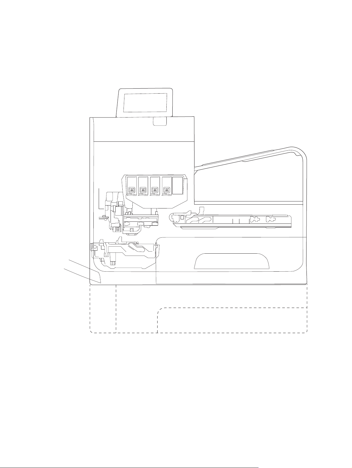
Figure 1-2 Main components (X585 models)
Document feeder
Optical
scan
carriage
Control panel
Scanner
Output bin
Printbar
Multipurpose tray
(Tray 1)
Duplex module\
Waste ink module
The product contains the following systems:
●
Engine control system
●
Print subsystem
Service sled
Main input tray (Tray 2)
Optional tray (Tray 3)
●
Paper-handling system
●
Servicing system
ENWW Basic operation 3
Page 20

●
Aerosol management system
●
Scanner and document feeder system (X585 models)
Two elements influence the product architecture:
●
Orienting the printbar with its active face downward and statically located above the print media. This
requires the printbar to move vertically to access its active face.
●
Producing face-down output. Rather than ejecting the page face-up immediately after the ink is
applied, as many inkjet printers do, the printed page is routed up and back over the printbar to eject
face-down.
Operation sequence
The engine-control system on the formatter PCA controls the operational sequences. The following table
describes durations and operations for each period of a print operation from when the product is turned on to
when the motors stop rotating.
Table 1-1 Operation sequence
Period Duration Purpose
Initial startup and
calibrations
Servicing operations When the printbar is entering
When the product is set up for
the first time from the factory.
the capping state after printing,
when leaving capping state after
a print job is initiated, or during
extended print jobs.
This period gets the product ready to print for the first time.
●
The product flushes the shipping and handling fluid out of the
printbar and replaces it with ink.
●
Die alignment—The product aligns the 10 die on the printbar
active face.
●
Die density leveling—The product measures and compensates
for the drop variation.
Servicing maintains the print quality by ensuring debris and excess
ink are removed and missing nozzles are replaced.
●
Nozzle presence detection—The optical scan carriage detects
and disables inoperable nozzles, and replaces them with
operable nozzles.
●
Printbar servicing—The web wipe on the service sled moves
under the printbar to clean the active face and fire the nozzles
into the waste ink module to clear clogs.
4 Chapter 1 Theory of operation ENWW
Page 21

Table 1-1 Operation sequence (continued)
Period Duration Purpose
Print preparation From the time the product
receives a print command until
paper enters the print zone.
Printing From the end of the preparation
period until the last sheet is
delivered.
Prepares the product for a print job.
●
The printbar leaves the capping state as the service sled
moves away from the printbar.
●
If needed, some servicing occurs.
●
The printbar lowers to the printing position. The media type
and printing mode determine the print zone height.
●
The product picks media from one of the input trays.
●
Every page from Tray 1 is scanned. For Tray 2 and optional
Tray 3, the product performs media edge detection after
printing the first sheet after the main or optional tray is
loaded. The last sheet of each job is also scanned if at least
five sheets have been printed.
●
The product monitors environmental conditions. The product
can decrease the print speed if conditions are significantly
different from a normal office environment (23 degrees C (73
degrees F), 50% relative humidity).
●
The formatter PCA processes print data and transmits the data
to the printbar.
Processes the print job.
●
As the page travels through the print zone, the printbar
applies ink to the page.
●
Simplex print job: the page moves up, over the printbar, and
out to the output bin (face-down).
●
Duplex print job: the page moves up until the trailing edge is
40 mm past the star-wheel jam reflective sensor, then
reverses direction down through the duplex path underneath
the waste ink module, and then reenters the print zone where
the printbar applies ink to the second side.
●
The process continues until all the pages of the print job are
completed. Occasional nozzle presence detection and
servicing events might occur if the job includes many pages.
ENWW Basic operation 5
Page 22

Table 1-1 Operation sequence (continued)
Period Duration Purpose
End of print job Performed after the print job is
completed, and continues until
the next job is initiated.
Standby The product is sitting idle,
waiting for the next print job to
be initiated.
Puts the product in a state where it’s ready for the next print job.
●
If needed, some servicing occurs.
●
The printbar moves to the capping position after a short dwell
interval.
●
The service sled moves to cap the printbar.
Conserves energy while the product is sitting idle. Certain functions
might be disabled to save power, then are restarted when needed.
The product has three sleep modes:
●
Idle mode—The printbar is capped and the product is ready to
immediately start a new job
●
Sleep1 mode—After the product is inactive for about 10
minutes, the control panel dims and the power LED blinks to
indicate the unit is in Sleep1. All product functions are
available. This setting can be adjusted from the control panel.
●
Sleep2 mode—After the product is inactive for a longer period
of time (typically 2 hours), the engine controller powers down
to minimize power consumption. This setting can be adjusted
from the control panel.
6 Chapter 1 Theory of operation ENWW
Page 23

System control
The system control coordinates all the other systems, according to commands from the formatter.
Figure 1-3 System control
I/O
Formatter
I/O, PDL, UI control
Scanner/
document feeder
(X585 models)
Power supply
Datapath
ASIC +memory
Engine control
Motor + sensor drive
Pen I/F
• Pen energy control
• Pen voltage
sequencing
• Signal integrity
• Ink-short protection
• Printhead
interconnects
• Ink supply
Printbar
40,000 nozzles
The system consists of the following major sections:
●
Formatter
●
Data path
●
Engine control
●
Pen interface
●
Scanner/document feeder (X585 models)
●
Power supply
The engine control electronics are located on the engine control board (ECB). The formatter PCA is a separate
assembly. The fax module (X585 models) is attached to the formatter PCA.
Formatter and data path
The formatter controller ASIC controls the input/output (I/O) control, the user interface, and the rendering of
page description language files into printer-specific commands.
Input/output (I/O) control
The products support 10/100 Ethernet, a rear USB host port, a rear USB device port, a control panel USB host
port, and analog fax port (some X585 models). For Ethernet networks, the formatter PCA uses a separate
integrated circuit (Broadcom 57761) to provide the physical network interface.
The formatter PCA also controls the USB device and USB host.
User interface
The products contain either a 4.2-in (X555 models) or an 8-in (X585 models) color graphics display. The
control panels include a USB host port for connection to thumb drives.
Formatter digital ASIC
The formatter digital ASIC has an ARM CPÙ (792 MHz) that executes firmware code that provides high-level
device control. The digital ASIC uses a standard PCle interface to pass data to the engine control ASIC. The
ENWW System control 7
Page 24

formatter firmware is located on either a rotating hard disk drive (HDD) or, on some X555 models, a solid
state drive (SSD).
Additionally, the formatter digital ASIC manages the real-time clock, interfaces to the mass storage
controller ASIC, provides control of USB ports, and interfaces with the Ethernet LAN ASIC and fax module.
Formatter Ethernet ASIC
The formatter Ethernet ASIC connects to the formatter digital ASIC with a PCIe interface to transmit and
receive network packets.
Formatter mass storage ASIC
The formatter mass storage ASIC bridges between the formatter digital ASIC (via PCIe interface) and the mass
storage device (via SATA interface). Both HDD and SSD mass storage media are supported. The X585 models
all use a rotating media HDD, while the X555 models use either HDD or SSD depending upon the bundle
option.
Formatter memory
Formatter memory is installed on-board and there is no support for additional DIMM memory installation.
The size of the memory on the formatter is fixed at 1 GB.
Real-time clock
The real-time clock (RTC) allows the fax module to time-stamp outgoing faxes. It also determines the
elapsed time between printhead and ISS calibration events. The RTC uses a separate device connected to the
formatter digital ASIC, along with a crystal and a battery.
Engine control
The engine controller digital ASIC receives high-level commands from the formatter, and then provides lowlevel control to the print mechanism. The engine controller digital ASIC and its firmware control motors,
system sensors, and the printbar. The engine controller analog ASIC integrates motor drivers, voltage
regulators, sensor interfaces, and supervisory circuits.
Engine controller digital ASIC
The engine controller digital ASIC has a high-performance 480 MHz ARM CPU and DSP co-processors that
execute firmware code to provide low-level engine control. It also drives the printbar via 15 high-speed LVDS
transmission lines, which are routed from the engine PCA to the printbar via two large FFC cables. The engine
controller digital ASIC receives pre-rendered data from the formatter digital ASIC over a standard PCle
interface.
In some product sleep modes, the digital ASIC powers down. If a print job is received while the product is in
this mode, power resumes to the digital ASIC, which then must “boot up”. This can take approximately 15
seconds, which will delay the first page out (FPO) time accordingly. This sleep mode typically begins after two
hours of product inactivity.
Engine controller analog ASIC
The engine uses two analog ASICs to generate the system voltages for the engine, drive the engine motors,
control various engine sensors, and monitor printbar power delivery for correct operation.
The engine has seven motors, some of which are shared with other subsystems:
8 Chapter 1 Theory of operation ENWW
Page 25

●
Pick motor
●
Feed motor
●
Duplex motor
●
Lift motor
●
Eject motor
●
Sensor carriage motor
●
Aerosol fan motor
Each one is a DC motor with encoder feedback, to provide precision servo control. These motors are driven
directly by one of the engine analog ASICs. Small DC motors also are used to drive the ISS pump and the
aerosol fan. Solenoids actuate the ejection flap and the ISS priming system.
The product uses many sensors to track the media as it travels through the paper path. Most of these are
optical REDI sensors, which are used in conjunction with mirrors to sense the presence or absence of paper in
a particular location. These are carefully aligned and calibrated at the factory, so care must be taken when
servicing these sensors. See the Remove and Replace chapter in the repair manual for more details.
Other printed circuit-board assemblies (PCAs)
In addition to hosting the system ASICs, the engine PCA is home to many circuits needed to interface to
sensors and other sub-system components. In some cases, this circuitry is located on a smaller remote PCA
(SLB) to optimize cable interconnects.
●
Humidity sensor—The humidity sensor causes the product to adjust printing speed if ambient
conditions are outside the optimal humidity range. This sensor is calibrated at the factory to ensure
maximum accuracy.
●
Temperature sensor—The temperature sensor causes the product to adjust printing speed if ambient
conditions are outside the optimal temperature range. In some products, this sensor resides on a
separate, remote PCA.
●
Main tray presence sensor—The hall-effect sensor that detects if the main tray is properly engaged
resides on the back of the engine PCA. A small magnet on the back of the main tray actuates the sensor.
If the tray is fully engaged, the magnetic field strength is sufficient to trigger the sensor.
Additionally, the product includes the following PCAs:
●
Fax PCA—Governs the product fax module.
●
Duplex module presence sensor—A hall-effect sensor that detects that the duplex module is properly
seated.
●
Power button PCA—Includes the power button and power LED, as well as interface cables to the duplex
module presence sensor and the MP tray empty REDI sensor.
●
Accessory tray interconnect PCA—Provides communication to optional Tray 3.
●
Pick encoder distribution PCA—Includes the pick motor encoder and the pick motor interconnect cable.
●
Eject encoder distribution PCA—Includes the eject motor encoder and the interconnect cables to the
eject motor and the aerosol fan.
ENWW System control 9
Page 26

●
Print zone distribution PCA—Joins interconnect cables to the following sensors: separator REDI, feed
motion encoder, main tray empty sensor, feed roller OOPs REDI sensor, and the starwheel jam REDI
sensor.
●
REDI distribution PCA—Includes hall-effect sensors that detect ink cartridge door and left door
positions. It also combines the interconnect cables for the eject jam REDI sensor, the upper drying path
REDI sensor, the lower drying path REDI sensor, and the eject flap opto flag sensor.
●
Sensor carriage PCA—Includes a carriage motion encoder, a ZIM sensor, and the BDD sensor.
●
Printbar lift encoder distribution PCA—This PCA includes the printbar lift motion encoder, and combines
interconnect cables to the printbar lift motor, carriage motor, and eject flap solenoid.
●
Duplex encoder PCA—Contains the motion encoder for the duplex motor.
●
SHAID PCA —Contains interfaces to the out-of-ink sensors for the ink cartridges, and combines the
interface cables to the acumen PCA, the ISS pump, and the ISS solenoids.
●
Acumen PCA—Contains interfaces to the acumen memory devices for the ink cartridges.
Pen interface (I/F)
The printbar is the key component that differentiates this product from other inkjet printers. The
conventional approach is to print a page in horizontal swaths by moving a “scanning” printhead horizontally
over a fixed sheet of paper, advancing the paper a fixed amount, and then printing the next swath. With this
product, the paper moves underneath a fixed page-wide printhead in a single smooth motion.
Single pass page-wide printing requires that data and power be delivered to the printbar at a very high rate,
while also maintaining good control of paper position as it moves past the printhead nozzles.
The engine PCA sends power and data to the printbar via two large flat flexible cables (36 and 38 pins). The
printbar PCA routes power and data to 10 printhead die, which are attached to the PCA using a flexible tab
circuit and wire-bonding process.
Electronics control the ink supply station (ISS). The SHAID PCA detects low-ink conditions. It gauges ink levels
by electrically sensing the presence of ink and/or ink foam in the X-chamber. The SHAID PCA also collects and
distributes electrical signals that drive the push-prime pump(s), engage the solenoids, and read the ink
supply acumen data. All are routed through a single 17-pin FFC from the SHAID PCA to the engine PCA.
Each ink supply has a memory tag that stores information about its type of ink, the amount of ink remaining,
and other critical data. It uses a special authentication scheme to ensure that only genuine HP supplies are
used and the product is not damaged by using invalid supplies. Acumen uses a two-line serial bus, which,
along with 3.3 V and ground, is cabled via the SHAID PCA to the engine PCA and the engine control digital
ASIC.
Power supply
The power supply module converts 100-240 VAC to 33 VCD and 5.1 VCD to power the system. The 33 V rail
goes to the engine and the scanner/document feeder, and the 5.1 V rail is supplies power to the formatter.
The power supply module has a sleep mode that reduces power consumption in system low-power modes.
The power supply module has four operating modes, depending on certain control signals, as outlined in the
table below. The power supply has a power factor correction (PFC) circuit to improve efficiency when the
system is in the active mode.
10 Chapter 1 Theory of operation ENWW
Page 27

Table 1-2 Power supply module operating modes
Mode n33V_OFF input signal nPFC_OFF input signal PFC Status 33 V rail status 5.1 V rail status
OFF Low Low Off Off On
Sleep 2 Low Low Off Off On
Sleep 1 High Low Off On On
Active High High On On On
The power supply is a self-contained module that can be replaced if it is defective (see the Remove and
Replace chapter of the Repair Manual).
To ensure safe operation, the power supply will “latch off” if a persistent over-current fault condition exists.
This is typically caused by a short-circuit from 33 V or 5.1 V to ground in the product. Less severe faults also
can cause the power supply to latch off, if present for an extended period of time, or if the product is
operated above the recommended operating range.
ENWW System control 11
Page 28

Print subsystem
The print subsystem includes the following components:
●
Printbar
●
Printbar lift
●
Ink cartridges
●
Optical scan carriage
Figure 1-4 Print subsystem components (X555 models)
Optical
scan
carriage
Ink cartridges
Printbar lift
Printbar
12 Chapter 1 Theory of operation ENWW
Page 29

Figure 1-5 Print subsystem components (X585 models)
Ink cartridges
Optical
scan
carriage
Printbar lift
Printbar
Printbar
The printbar converts the digital firing instructions from the product electronics into properly formed and
timed microscopic drops of the four ink colors. The printbar spans the full width of a letter/A4-size sheet
(216 mm (8.5 in)), which allows it to be statically positioned within the product and have the media move
underneath it, printing the entire page in a single motion.
ENWW Print subsystem 13
Page 30

Figure 1-6 Printbar components
1
4
23
Table 1-3 Printbar components
Item Description
1 Ink cartridge connections
2 Thermal inkjet (TIJ) die array
3 Data/power flow and regulation
4 Inkflow channels and pressure regulation
The printbar has a fixed array of 10 thermal inkjet (TIJ) die oriented in two staggered rows. Each die contains
over one thousand nozzles for each of the four ink colors (black (K), cyan (C), magenta (M) and yellow (Y)).
Behind the die array are the ink flow channels and pressure regulation mechanisms that supply the die array
with ink at the proper pressure and flow. Onboard electronic circuitry feeds power and data to the die at the
appropriate levels and rates. Four ink cartridge receptacles, one for each color, are located at the top of the
printbar. Flow connections link these cartridges to the rest of the printbar to supply the ink necessary for its
operation.
A sensor technology called back-scatter drop detect (BDD) monitors printbar health and calibrations. This
system looks at the reflection of the miniscule drops in flight and passes these signals through proprietary,
advanced high-speed, high-gain, bandpass filters. An artificial intelligence (AI) system decides which drop
ejectors are currently in or out of specifications.
After the AI system determines which drop ejectors are out of specification, the product compensates for
them. Some ejectors use neighboring nozzles and at times even tiny amounts of other inks – whichever
combination of methods necessary to deliver the best print quality possible at that moment. Up to half of the
nozzles can be “out” without a noticeable degradation in quality. The compensation is done in real time with
a dedicated high-speed DSP. The system can scan portions of the system after print jobs, but it is fully
interruptible by new incoming print jobs.
Printbar lift
The printbar lift positions the printbar within the product and moves it up and down as required. This vertical
motion establishes proper spacing to the paper during printing. It also raises the printbar to access the active
face or perform necessary calibrations.
14 Chapter 1 Theory of operation ENWW
Page 31

During printing, the lift mechanism sets the printbar height and paper height depending on the type of paper.
Ink cartridges
This product has new, state-of-the-art pigmented inks. They are filtered using proprietary processes to
prevent printhead contamination. These inks are designed to produce optimal print quality on ColorLok office
papers, but also produce very good print quality on regular office papers and specialty media.
Optical scan carriage
The optical scan carriage has optical sensors used for calibration. Its motion is along the long axis of the
printbar. These sensors are used by a number of in-printer calibration features that are important for proper
subsystem function. The BDD sensor is located on the optical scan carriage.
Print system operational states
The print subsystem has a number of distinct operational states besides active printing.
Startup
As it comes from the factory, the printbar is initially filled with an inert ink-substitute called Shipping and
Handling Fluid (SHF). This fluid, essential for the manufacture and transportation of the printbar, must be
flushed and replaced with actual ink. This is accomplished during the Startup phase. The flushing process
automatically commences when ink supplies are inserted and the unit powered up for the first time. The SHF
is removed by sustained printbar operation and replaced by ink from the supplies. The process terminates
once all the SHF has been flushed from the printbar.
Special host supplies are supplied with the product prior to its first use. These supplies contain additional ink
so that there will be 100 percent ink level after the SHF is replaced with ink. These supplies can be used only
to initialize the product. You cannot use them in another product that has been initialized.
NOTE: The initial startup time is noticeably longer than the following regular startup times.
Die alignment
Die alignment is done by printing a special diagnostic image on a sheet of paper and then scanning it with the
optical scan carriage. It is performed as part of initial unit startup, and can be manually invoked as part of the
print quality recovery tool. Die alignment calibrates the positions of the 10 die. It also allows a uniform
application of ink to the media, without gaps or overlaps between adjacent die.
Die density leveling
A set of diagnostic images is printed and scanned by the optical scan carriage to achieve uniform application
of ink droplets to the media. Die alignment and die density leveling are usually paired together.
Nozzle presence detection
In printing, since all the ink is applied in a single smooth motion of the media past the printbar, any
inoperable nozzle can show up as a streak. The operational state of each of the thousands of nozzles on the
printbar is periodically measured. The printbar is raised by the printbar lift, and the BDD assembly on the
optical scan carriage watches for drop presence as each nozzle is fired. Inoperable nozzles are turned off and
other operable nozzles used on subsequent printed pages to apply the missing ink. Nozzle presence
detection is fully interruptible by new incoming print jobs.
ENWW Print subsystem 15
Page 32

Media edge position detection
The product uses a learning algorithm to define media center as a function of input source—multipurpose
tray, main tray, or accessory tray. The edge scan is located downstream of the print zone. As media is
scanned, the media center database is updated. The image is registered to the page using the media center
database.
Servicing and capping
When in the capped state, the printbar is fully raised, the service sled is positioned underneath, and the
printbar cap is engaged against the printbar active face. Servicing—the cleaning of the active face and the
firing of the nozzles—can occur either during Sleep2 mode or after extended time in storage. It can also
occur during extended print jobs.
Printing
The printing state begins by the printbar leaving the capping state, and being lowered to the printing position
after the service sled moves out of the way. At the same time, a sheet of media is picked from one of the
three trays and the leading edge staged at the entrance to the print zone. Once the print data has been sent,
the media sheet is fed at a constant velocity through the print zone and the ink applied by the printbar.
In the case of one-sided printing the inked sheet is conducted up, over and out to the output tray. For twosided printing the sheet is moved until its trailing edge is past the merge to the vertical path, and then it is
reversed down through the duplex path underneath the waste ink module, and reintroduced into the print
zone for inking of the second side.
This process continues until all the pages of the print job are completed, perhaps being interrupted by
servicing events if the job is many pages.
16 Chapter 1 Theory of operation ENWW
Page 33

Paper-handling system
The paper-handling system moves paper through the product according to commands from the formatter.
The following figure shows the product paper path.
Figure 1-7 Paper-handling system paper path (X555 models)
ENWW Paper-handling system 17
Page 34

Figure 1-8 Paper-handling system paper path (X585 models)
The paper path consists of the following major components:
●
Two integrated input trays plus one optional accessory tray
●
Four motors and a solenoid plus two more motors in the accessory tray
●
Duplex module
●
Fourteen sensors plus four more sensors in the accessory tray
18 Chapter 1 Theory of operation ENWW
Page 35

●
Feed rollers, pinch rollers, star wheels, and media guides
●
Transmission components (gears, shafts, levers, swing arms) that interface with other subsystems such
as the printbar and service sled.
Components of the paper path move the paper from the input tray to a position 1 to 2 mm underneath the
printbar, and then deliver the printed result to the output tray. The combined orientations and actions of the
printbar, the printbar lift, and the paper path establish the print-zone, where the ink drops move from the
active face of the printbar to the paper.
The following figure shows the product sensors.
Figure 1-9 Product sensors (X555 models)
24
23
22
21
20
19
18
17
16
15
14
1
2
3
13
12 11 10 89 999997 6 45
ENWW Paper-handling system 19
Page 36

Figure 1-10 Product sensors (X585 models)
24
23
22
21
20
19
18
17
16
15
14
1
2
3
13
12 11 10 89 999997 6 45
Table 1-4 Product sensors
Item Description Item Description
1 Output flap jam sensor 13 Feed roller jam sensor
2 Ambient temperature sensor 14 Feed roller encoder
3 Ambient humidity sensor 15 Feed roller home sensor
20 Chapter 1 Theory of operation ENWW
Page 37

Table 1-4 Product sensors (continued)
Item Description Item Description
4 Tray 2 pickup tire home sensor 16 Duplex module presence sensor
5 Tray 2 tray presence sensor 17 Star-wheel jam sensor
6 Tray 3 pickup tire home sensor 18 Back-scatter drop detect sensor
7 Tray 3 paper presence sensor 19 Print calibration/Media edge detect sensor
8 Tray 3 separation sensor 20 Lower left door jam sensor
9 Tray 2 paper presence sensor 21 Left door open sensor
10 Tray 3 tray presence sensor 22 Upper left door jam sensor
11 Tray 1 paper presence sensor 23 Ink supply door open sensor
12 Tray 3 cleanout presence sensor 24 Eject jam sensor
There are several motors in the product for pick, feed, duplexing, printbar lift, delivery, and the scanning
sensor carriage.
ENWW Paper-handling system 21
Page 38

Figure 1-11 Paper-handling-system motors (X555 models)
8
7
6
1
5
234
22 Chapter 1 Theory of operation ENWW
Page 39

Figure 1-12 Paper-handling-system motors (X585 models)
8
1
7
6
5
234
Table 1-5 Paper-handling system motors
Item Description
1 Eject (or output drive) motor
2 Tray 2 pickup motor
3 Tray 3 pickup motor
ENWW Paper-handling system 23
Page 40

Table 1-5 Paper-handling system motors (continued)
Item Description
4 Duplex Tray 1 motor
5 Tray 3 feed motor
6 Feed motor
7 Optical carriage motor
8 Printbar lift motor
Input trays
The product comes standard with two input trays, and also accepts an accessory tray.
●
●
50-page multipurpose (MP) tray—Tray 1: The tray shares a motor with the duplex module and has one
sensor. This reflective (REDI) sensor determines if media is present in the tray. The feed roller REDI
sensor determines if a sheet of media is successfully picked from the tray.
500-sheet letter/A4 size main tray—Tray 2: The tray has a pick motor, which is also moves the service
sled. Both the main tray motor and the duplex MP tray motor operate at the same time when picking
paper from the main tray. The main tray has three sensors:
◦
A hall effect sensor determines if the tray is closed.
◦
A flag/opto sensor determines if there is media in the tray.
◦
A flag/opto sensor determines if the pick roller is in home position.
The feed roller jam sensor determines if a sheet of media is successfully picked from the main tray.
●
Optional 500-sheet legal size accessory tray—Tray 3: This optional tray has two motors, one for picking
paper and one for the turn roller. The turn roller receives paper from the pickup roller and transfers it to
the multipurpose tray ITR that is driven by the duplex module/MP tray motor. Both the accessory tray
motor and the duplex module/MP tray motor operate at the same time when picking paper out of the
accessory tray.
The accessory tray has the following sensors:
◦
A hall effect sensor detects if the tray is closed.
◦
A flag/opto sensor detects if there is media in the tray.
◦
A flag/opto sensor detects if the pickup roller is in home position.
◦
A hall effect sensor detects if the left door is closed.
◦
A separation sensor detects if the product successfully picked media.
Paper path zones
The product paper path includes the following elements.
●
Deskew buckle
●
Print zone
24 Chapter 1 Theory of operation ENWW
Page 41

●
Duplex
●
Output
●
Eject
Figure 1-13 Paper path zones (X555 models)
5
4
1
3
2
ENWW Paper-handling system 25
Page 42

Figure 1-14 Paper path zones (X585 models)
5
1
4
3
2
Table 1-6 Paper path zones
Item Zone Description
1 Deskew buckle This is the area between the turn roller and feed roller. All print job paper passes through this zone.
During the deskew operation, the duplex module/MP tray motor rotates forward, driving the paper
into the feed roller nip while the feed roller is not moving. The feed roller REDI sensor determines the
leading edge for accurate deskew buckle size, jam detection, and if the tray successfully picked
media.
26 Chapter 1 Theory of operation ENWW
Page 43

Table 1-6 Paper path zones (continued)
Item Zone Description
2 Print zone This is the path between the feed roller and output pinch 1 roller. The feed roller, which has an analog
quadrature encoder, precisely controls the paper in the paper feed direction . In the vertical direction,
a combination of the platen, feed roller, and output pinch roller 1 controls the paper. The user can
rotate the platen down for jam access after removing the duplex module.
There are no paper path sensors in the print zone. If a jam occurs in the print zone, it is not detected
until the leading edge of the paper is determined to be “late” in reaching the jam sensor in the output
path.
When a user pulls on jammed media in the print zone that is still partially in the feed roller nip, the
servo control will detect a slight movement of the feed roller and assist the user by applying a
forward torque to the roller. Also, the motion control system will disengage the duplex module
rectifier (swing arm) so that the turn roller can spin freely. This feature reduces the pulling force
needed by the user and therefore reduces the chance of leaving torn pieces of paper in the path—
especially in the deskew buckle zone.
3 Duplex By opening the left door, the duplex module can be removed to clear jams. The duplex module also
serves as waste collection unit for the print bar and will expose the user to waste ink when it is
removed. Therefore there are warnings on the module to not touch certain areas.
When the user pulls on jammed media from the duplex module (or any of the trays) that is partially in
the feed roller nip, the servo control detects a slight movement of the feed roller and assists the user
by applying a reverse torque to the feed roller and disengages. Also, the motion control system
disengages the duplex module rectifier so the turn roller can spin freely. This feature reduces the
pulling force needed by the user and therefore reduces the chance of leaving torn pieces of paper in
the path—especially in the deskew buckle zone.
In order for the product to determine the duplex module's presence, the duplex module has a magnet
that triggers a hall effect sensor mounted to the structure.
4 Output The output path begins at output pinch roller 1 and continues to output pinch roller 5. There are four
REDI sensors in this path that detect leading and trailing edges and jams.
The feed motor drives the rollers in the output path, except output pinch roller 5. All the pinch rollers
in the output and exit path are star wheels to prevent roller tracking on wet/damp ink. However, the
turn roller pinch is solid and has a high amount of force for deskew buckle formation. Also, the feed
motor drives all output shafts except shafts 5 and 6.
The REDI dry path lower, REDI dry path upper, and eject jam REDI sensor in the output path all track
the leading and trailing edges of media.
The outer and top portions of the vertical path are formed by paper guides molded in and attached to
the left door. The left door can be opened for jam clearance and has a hall effect sensor to determine
if it is closed. Also when the left door is opened, drive rollers that form pinches 3 and 4 disengage
from the feed motor for safety purposes.
5 Eject The eject portion of the paper path includes the zone from output pinch roller 5 to the eject flap.
The eject motor powers output pinch roller 5 and eject pinch roller 6.
The eject flap has 3 positions:
●
Closed when not printing.
●
Partially open for heavy ink printing in dry environments, to limit severe curl.
●
Ofpen for all other printing. This position controls moderately curled media.
The flap is opened and closed by a torque clutch on the eject roller shaft. The flap also has a locking
feature that is controlled by a solenoid. In order for the door to open all the way, or move between
positions, the solenoid must be actuated.
ENWW Paper-handling system 27
Page 44

Servicing system
The servicing system comprises the service sled, which maintains print quality by wiping debris and ink off
the print nozzles, and the service ink module, where waste ink is deposited.
Figure 1-15 Servicing system components (X555 models)
Service sled
Duplex module\
Waste ink module
28 Chapter 1 Theory of operation ENWW
Page 45

Figure 1-16 Servicing system components (X585 models)
Duplex module\
Waste ink module
Service sled
ENWW Servicing system 29
Page 46

Service sled
Figure 1-17 Service sled components
1
Table 1-7 Service sled components
Item Description
1 Service sled cap
4
2
3
2 Service sled wiping surface
3 Service sled web fabric loop
4 Printbar support posts
The service sled system keeps the printbar nozzles firing correctly throughout the life of the product as it
performs the wiping and capping functions.
●
The wiping function cleans the nozzles of ink residue and particulates.
●
The capping function keeps the nozzles moist during storage when the product is idle.
The service sled system uses the pick drive system (a component of the paper path) for horizontal motion to
perform its functions.
To perform the wiping function, the product moves the service sled underneath the printbar (which is
elevated from the print position) so that the web fabric makes contact with the ink nozzles. The web fabric is
a looped belt that advances after every wipe. Since the belt is a finite loop, it will eventually reuse previously
used material. The web advances when the web wipe module moves to the right out of the print zone. The
advance mechanism is triggered by a mechanism located on the rear wall of the unit.
To perform the capping function, the service sled moves underneath the printbar (which is elevated from the
print position), which allows the rubber cap to seal the print nozzles from the environment.
30 Chapter 1 Theory of operation ENWW
Page 47

Aerosol management system
The aerosol management system consists of a fan module and filter box to keep ink aerosol from building up
inside the product. The following figure shows the service ink and aerosol capture system components.
Figure 1-18 Aerosol management process
Printbar
Paper
Platen
Spit
Roller
Absorbers
Service ink capture (in duplex module)
Between pages, printed aerosol is drawn though the platen openings. Service ink travels directly through the
platen, impacting and collecting on the spit roller. Aerosol from the service spitting is also collected. Service
ink collects in the duplex module, and a porous filter element captures the aerosol as aerosol-laden air
passes though it. The aerosol blower mounted to the filter housing creates the air motion (suction—lower
pressure—in the print zone).
Aerosol blower
Duplex
module
Duct
Aerosol filter
Most of printbar servicing ink (spit ink) is captured by the spit roller and scraped into the bottom of the
bucket on the duplex module. The service ink spit roller is indexed slowly by the motion of paper though the
product, driven by the swing-arm and turn-roller gear train, with power provided by the duplex motor.
When the product purges the printbar of its shipping fluid at initial startup, absorbers in the duplex module
collect the fluid. These absorbers allow much of the initial water to evaporate from the shipping fluid over
time. Also, they allow service ink coming into contact with the absorbers to leach some of their fluids into
them, assisting with drying and thickening of the sludge.
The blower remains active as long as the printbar is uncapped, and it continues to operate for a few seconds
after capping is complete.
ENWW Aerosol management system 31
Page 48

Figure 1-19 Aerosol management system components
1
2
Table 1-8 Aerosol management system components
4
3
Item Description
1Blower
2 Aerosol filter housing
3 Duplex module/waste ink module
4Platen
32 Chapter 1 Theory of operation ENWW
Page 49

Document feeder (X585 models)
Document feeder operation
Standby (paper-loading) mode: In standby mode, the pickup roller is up and the stack-stop is down,
preventing the user from inserting the original document too far. When a document is inserted correctly, the
paper-present sensor detects its presence.
The standard operation of the document feeder consists of the pick, feed, and lift steps.
Pick: When it receives a copy or scan command, the document feeder motor engages the gear train to lower
the pickup-roller assembly and raise the stack-stop. The pre-pick roller moves the top few sheets forward
into the document feeder. The pickup roller contacts the document feeder separation pad, which separates
multiple pages into single sheets.
Feed: The form sensor, which is a set distance from the document feeder glass, detects the sheet. This alerts
the scanner to start when the page reaches the glass. The scanner acquires the image until it detects the end
of the page. The page is then ejected. The pick and feed steps are repeated as long as paper is detected in the
document feeder input tray.
Duplex: When the product duplexes from the document feeder, the paper passes through the document
feeder three times. During the second instance, the product reverses the page orientation and then scans it.
During the third instance, the product returns the page to the original orientation.
Lift: When no more paper is detected in the document feeder input tray and the form sensor detects the
trailing edge of the last page, the last sheet is ejected and the motor lifts the pick-roller assembly to standby
(paper-loading) mode again.
The document feeder will not function when the document feeder cover is open. When the document feeder
cover is closed, the cover-present sensor detects its presence.
The paper path is incomplete if the scanner lid/document feeder is lifted from the glass, and it will result in a
paper jam error.
Document feeder paper path and sensors
The following diagram shows the document feeder paper path during a duplexed copy job. The paper enters
the product from the document feeder input tray and passes through the paper path for the first time. The
product then pulls the paper back through the path to reorient the page and scan the second side. The paper
then travels back to the end of the paper path, where it is pulled in again to be reoriented and ejected into the
output bin.
ENWW Document feeder (X585 models) 33
Page 50

Figure 1-20 Document feeder paper path and sensors
(1)
(1)
(1)
(1.2)
(1.2)
(1.2)
Flag TOP
Prepick roller
Document flag
Output roller
Output tray
Input tray
Stack Shop
(2)
Separation roller
Stack Shop
Stack shop
Prepick roller
Document flag
Document flag
Input tray
Input tray
(1)
(1)
(1.2)
Flag TOP
Flag TOP
Paper travel direction
(1.2)
Prepick roller
Prepick roller
Scan glass
The paper-present sensor determines if paper is in the document feeder input tray. The form sensor detects
the top and bottom edges of the document. Another sensor detects an open document feeder cover.
Document feeder jam detection
The document feeder has two sensors that detect paper. The paper-present sensor detects the presence of
media in the document feeder input tray. The form sensor detects media moving through the document
feeder. If a jam is detected, the document feeder immediately stops the paper feeding and initiates a jam
clearing routine. A jam message appears on the control-panel display.
A jam can be detected under any of the following conditions:
●
Document-feeder jam:When documents are detected in the document feeder input tray, and a
command to copy, scan or fax is received, the document feeder attempts three times, or for about 10
seconds, to advance the paper to the form sensor. If the paper does not advance, the scan module turns
off and the ADF Misfeed message appears on the control-panel display.
(2)
(2)
(1.2)
(1.2)
(1)
(1)
(1)
(1)
Output roller
Output roller
(1.2)
(1.2)
Paper pulled back
after first side scan
Output tray
Output tray
●
Long-document jam: If the paper has advanced to trigger the form sensor, but the trailing edge is not
detected within the time allowed for a 381 mm (15 in) document (the maximum allowable page length
for the document feeder), the scan module turns off and the message Paper Jam appears on the
control-panel display.
●
Stall jam: When a page that is less than 381 mm (15 in) long has advanced to the form sensor but has
not left it within the expected time, the paper has probably stalled or jammed. The scan module turns
off and the message Paper Jam appears on the control-panel display.
●
Other: If the paper stops in the document feeder and the scan module remains under the document
feeder scanner glass, an internal firmware error has probably occurred and the message Cannot Scan,
Copy, or Fax appears on the control-panel display. This is usually remedied by cycling the power.
34 Chapter 1 Theory of operation ENWW
Page 51

Scanner system (X585 models)
The flatbed image scanner captures an electronic image of the document on the glass. The scanner does this
by illuminating the document with LEDs (red, green, and blue) and capturing the image in the image sensor to
create an electronic image of the document. The flatbed scanner consists of three main elements
●
CIS scanner. The CIS (contact image sensor) scanner captures an image using the product's optical path.
Red, green, and blue LEDs sequentially illuminate a small strip of the document (often called a raster
line), and the optical system captures each color in a single row of CCD sensors that cover the entire
page width. Because only one color is captured for each line per exposure, the three colors are
recombined electronically to create the full color image. For monochromatic scans or copies, all three
LEDs are illuminated to create a white light for the scan so the raster line can be captured in one
exposure.
●
Mechanical carriage drive. The carriage drive moves the CIS scan head along the document length to
create the image. In this product, a small DC motor with an optical encoder creates this motion. The
speed of the carriage drive is proportional to the scan resolution (300 ppi is much faster than 1200 ppi)
and also proportional to the type of scan (color scans are three times slower than monochromatic
scans). A 1200 ppi color scan moves so slowly that the product might appear to not be working,
whereas a monochromatic copy scan moves at 50 times that speed and will be somewhat noisy.
●
Image processing system (formatter). The formatter processes the scanner data into either a copy or a
scan to the computer. For copies, the image data is sent directly to the product without being
transmitted to the computer. Depending on user selections for the copy settings, the formatter
enhances the scanner data before sending it to the product. Image data is captured at 300 ppi for copies
and is user selectable for scans to the computer. Each pixel is represented by 8 bits for each of the three
colors (256 levels for each color), for a total of 24 bits per pixel (24-bit color).
Scanner power-on sequence of events
When the product is turned on, it performs the following tests:
●
Motor test. The product moves the motor left and right to confirm operation. It reports a scanner error
12 if no motion is detected in the motor encoder system.
●
Wall find. The scan carriage moves slowly to the left while watching an encoder on the carriage motor
to determine when the carriage has found the side wall or stop. This enables the product to identify the
document origin (position of the original). If the document origin cannot be located, a default position is
used instead.
●
LED check. The product moves the carriage to the white calibration label under the left side of the
flatbed image scanner, and it verifies that the minimum and maximum response is acceptable. It
reports a scanner error 14 if the response is unacceptable.
●
Home find. The scan carriage uses the optical scanner to find physical reference features that relate to
the document origin at the left side of the image glass. This process ensures accurate location of the
first document pixels so that the user documents will have an accurate placement of the image on
scans and copies. It reports a scanner error 6 message if the reference features are not found.
●
Calibration. This test, also known as scanner color calibration, enables the product to identify the black
and white on every pixel in the CCD. Calibration occurs in two processes: a broad (analog) adjustment of
all pixels to bring them into the target output range, and a pixel-by-pixel adjustment (digital) to fine
tune the actual black and white response. The calibration process occurs under the left side of flatbed
image scanner where there is a special white calibration label. The calibration code in the product
firmware needs to be updated when the scanner assembly is replaced.
ENWW Scanner system (X585 models) 35
Page 52

Calibration is the most important step in creating a high quality image. Calibration problems can include
color and brightness inaccuracies and vertical streaks through the image. The calibration process
identifies any bad pixels and enables the image formatter to recreate the lost information from
adjacent pixels. Extreme cases of this problem can appear as large vertical streaks or image smears.
The user has no control over the calibration process itself or this pixel-replacement process.
For best calibration results, make sure that the scanner lid is in the down (closed) position.
Copy or scan-to-computer sequence of events
To create an accurate rendition of a document, the scanner must be calibrated for the requested operation. If
the user selects a scan at 600 ppi color, the flatbed image scanner calibrates for that specific operational
mode. The flatbed image scanner automatically re-calibrates for the next requested operation. Calibration
does not occur for every new copy request.
This is the normal sequence of operation for a flatbed copy or scan.
1. LEDs illuminate.
2. Carriage motion begins moving the CIS scanner toward the right.
3. Image capture continues for the entire page or length requested in a scan-to-computer operation.
4. Carriage returns to the home position on the left.
36 Chapter 1 Theory of operation ENWW
Page 53

Fax functions and operation (X585 models)
The following sections describe the product fax capabilities.
Computer and network security features
The product can send and receive fax data over telephone lines that conform to public switch telephone
network (PSTN) standards. The secure fax protocols make it impossible for computer viruses to be
transferred from the telephone line to a computer or network.
The following product features prevent virus transmission:
●
No direct connection exists between the fax line and any devices that are connected to the USB or
Ethernet ports.
●
The internal firmware cannot be modified through the fax connection.
●
All fax communications go through the fax subsystem, which does not use Internet data-exchange
protocols.
PSTN operation
The PSTN operates through a central office (CO) that generates a constant voltage on the TIP and RING wires
(usually 48 V). A device goes off-hook by connecting impedance (such as 600 ohms for the U.S.) across the
TIP and RING so that a line current can flow. The CO can detect this current and send impulses like dial tones.
The product generates more signaling tones, such as dialing digits, to tell the CO how to connect the call. The
product can also detect tones, such as a busy tone from the CO, that tell it how to behave.
When the call is connected, the CO behaves like a wire connecting the sender and receiver. This is the period
during which all of the fax signaling and data transfer occurs. When a call is completed, the circuit opens
again and the line-current flow ceases, removing the CO connection from both the sender and the receiver.
On most phone systems, the TIP and RING signals appear on pins 3 and 4 of the RJ-11 modular jack (the one
on the fax card, as defined in the common six-wire RJ standard). These two signals do not have to be
polarized because all of the equipment works with either TIP or RING on one pin and the other signal on the
other pin. This means that cables of either polarity can interconnect and still work.
These basic functions of PSTN operation are assumed in the design of the fax subsystem. The product
generates and detects the signaling tones, currents, and data signals that are required to transmit and
receive faxes using the PSTN.
The fax subsystem
The formatter, fax card, firmware, and software all contribute to the product fax functionality. The designs of
the formatter and fax card, along with parameters in the firmware, determine the majority of the regulatory
requirements for telephony on the product.
The fax subsystem is designed to support V.34 fax transmission, medium speeds (such as V.17 fax), and the
lower speeds of older fax machines.
Fax card in the fax subsystem
The fax card contains the modem chipset (DSP and CODEC) that controls the basic fax functions of tone
generation and detection, along with channel control for fax transmissions. The CODEC and its associated
circuitry act as the third-generation silicon data access arrangement (DAA) to comply with worldwide
regulatory requirements.
ENWW Fax functions and operation (X585 models) 37
Page 54

Safety isolation
The fax card provides safety isolation between the high-voltage, transient-prone environment of the
telephone network (TNV [telephone network voltage]) and the low-voltage analog and digital circuitry of the
formatter (SELV [secondary extra-low voltage]). This safety isolation provides both customer safety and
product reliability in the telecom environment.
Any signals that cross the isolation barrier do so magnetically. The breakdown voltage rating of barriercritical components is greater than 5 kV.
Safety-protection circuitry
In addition to the safety barrier, the fax card protects against over-voltage and over-current events.
Telephone over-voltage events can be either differential mode or common mode. The event can be transient
in nature (a lightning-induced surge or ESD) or continuous (a power line crossed with a phone line). The fax
card protection circuitry provides a margin of safety against combinations of over-voltage and over-current
events.
Common mode protection is provided by the selection of high-voltage-barrier critical components
(transformer and relay). The safety barrier of the fax card PCA and the clearance between the fax card and
surrounding components also contribute to common mode protection.
A voltage suppressor (a crowbar-type thyristor) provides differential protection. This device becomes low
impedance at approximately 300 V differential, and crowbars to a low voltage.
Data path
TIP and RING are the two-wire paths for all signals from the telephone network. All signaling and data
information comes across them, including fax tones and fax data.
The telephone network uses DC current to determine the hook state of the telephone, so line current must be
present during a call. The silicon DAA provides a DC holding circuit to keep the line current constant during a
fax call.
The silicon DAA converts the analog signal to a digital signal for DSP processing, and also converts the digital
signal to an analog signal for transmitting data through a telephone line.
The magnetically coupled signals that cross the isolation barrier go through a transformer.
The DSP in the fax card communicates with the ASIC in the formatter using the high-speed serial interface.
Ring detect
Ring detect is performed by the line voltage monitoring module of the silicon DAA, and is a combination of
voltage levels and cadence (time on and time off). Both must be present to detect a valid ring. The CODEC
works with DSP and the firmware to determine if an incoming signal is an answerable ring.
Line current control
The DC current from the CO needs to have a path to flow from TIP to RING. The DC impedance emulation line
modulator and DC terminations modules in the silicon DAA act as a DC holding circuit, and work with the
firmware to achieve the voltage-current characteristic between TIP and RING. The impedance (the currentvoltage characteristic) changes corresponding to certain special events, such as pulse dialing or when the
product goes on-hook.
38 Chapter 1 Theory of operation ENWW
Page 55

Fax page storage in flash memory
Fax pages are the electronic images of the document page. They can be created in any of three ways:
scanned to be sent to another fax machine, generated to be sent by the computer, or received from a fax
machine to be printed.
The product automatically stores all fax pages in flash memory. After these pages are written into flash
memory, they are stored until the pages are sent to another fax machine, printed on the product, transmitted
to the computer, or erased by the user.
These pages are stored in flash memory, which is the nonvolatile memory that can be repeatedly read from,
written to, and erased. The product has 2 MB of flash memory, of which 1.5 MB is available for fax storage.
The remaining 0.5 MB is used for the file system and reclamation. Adding RAM does not affect the fax page
storage because the product does not use RAM for storing fax pages.
Advantages of flash memory storage
Fax pages that are stored in flash memory are persistent. They are not lost as a result of a power failure, no
matter how long the power is off. Users can reprint faxes if an ink cartridge runs out of ink or the product
experiences other errors while printing.
The product also has scan-ahead functionality that makes use of flash memory. Scan-ahead automatically
scans pages into flash memory before a fax job is sent. This allows the sender to pick up the original
document immediately after it is scanned, eliminating the need to wait until the fax transmission is complete.
Because fax pages are stored in flash memory rather than RAM, more RAM is available to handle larger and
more complicated copy and print jobs.
ENWW Fax functions and operation (X585 models) 39
Page 56

40 Chapter 1 Theory of operation ENWW
Page 57

2 Solve problems
●
Problem-solving checklist
●
Troubleshooting process
●
Tools for troubleshooting
●
Control-panel menus
●
Solve image quality problems
●
Solve paper jam or feed problems
●
Solve performance problems
●
Solve connectivity problems
●
Service mode functions
●
Solve fax problems
●
Product upgrades
ENWW 41
Page 58

Problem-solving checklist
Follow these steps when trying to solve a problem with the product.
●
Step 1: Check that the product power is on
●
Step 2: Check the control panel for error messages
●
Step 3: Test print functionality
●
Step 4: Test copy functionality
●
Step 5: Test the fax sending functionality
●
Step 6: Test the fax receiving functionality
●
Step 7: Try sending a print job from a computer
●
Step 8: Test the Plug and Print USB Drive printing functionality
●
Factors that affect product performance
Step 1: Check that the product power is on
1. Make sure that the product is plugged in and turned on. The power button should be lit with a green
light. If it is not, press the power button. It should first glow with an amber color, and then quickly
switch to green as the product initializes. If the power button does not light up, check the following
conditions.
●
Make sure that the power cable is connected to the product and the outlet.
●
Check the power source by connecting the power cable to a different outlet.
2. If the product motors do not rotate, make sure that the ink cartridges are installed and that the doors
are all closed. The control panel displays messages to indicate these problems.
3. If the document feeder motor does not rotate, open the document feeder cover and remove any
packing material or shipping tape.
4. If the scanner bulb does not light during copying, scanning, or faxing, contact HP support.
Step 2: Check the control panel for error messages
The control panel should indicate ready status. If an error message appears, resolve the error.
Print a supplies status page to ensure that the supplies are not at or over end of life.
●
Ink collection unit (B5L09A): estimated life is 115,000 pages.
●
Document feeder (ADF) roller kit, X585 models only (L2718A): estimated life is 100,000 pages.
NOTE: HP long-life consumable and maintenance kit life specifications are estimations. Actual individual
life or yield during normal use will vary depending on usage, environment, media, and other factors.
Estimated life is not an implied warranty.
42 Chapter 2 Solve problems ENWW
Page 59

Step 3: Test print functionality
1. From the control panel Home screen, touch the Administration button.
2. Open the Reports menu, touch the Configuration/Status Pages menu, select the Configuration Page
item, and then touch the Print button to print the report.
3. If the report does not print, make sure that paper is loaded in the tray, and check the control panel to
see if paper is jammed inside the product.
NOTE: Make sure that the paper in the tray meets specifications for this product.
Step 4: Test copy functionality
1. Place the configuration page into the document feeder and make a copy. If paper does not feed
smoothly through the document feeder, you might need to clean the document feeder rollers and
separation pad. Make sure that the paper meets specifications for this product.
2. Place the configuration page onto the scanner glass and make a copy.
3. If the print quality on the copied pages is not acceptable, clean the scanner glass and the small glass
strip.
Step 5: Test the fax sending functionality
1. From the control panel Home screen, touch the Administration button.
2. Open the Fax Setup menu, and then open the Fax Tools menu. Touch the Run Fax Test button to test the
fax functionality.
3. Touch the Fax on the product control panel, and then touch the Start Fax button.
Step 6: Test the fax receiving functionality
1. From the control panel Home screen, touch the Administration button.
2. Touch the Fax Setup menu, and then touch the Fax Tools menu. Touch the Run Fax Test button to test
the fax functionality.
3. Use another fax machine to send a fax to the product.
4. Review and reset the product fax settings.
Step 7: Try sending a print job from a computer
1. Use a word-processing program to send a print job to the product.
2. If the job does not print, make sure that you selected the correct printer driver.
3. Uninstall and then reinstall the product software.
ENWW Problem-solving checklist 43
Page 60

Step 8: Test the Plug and Print USB Drive printing functionality
1. Load a .PDF document or .JPEG photo onto a USB flash drive, and insert it in the slot on the front of the
product.
2. The USB Flash Drive menu opens. Try printing the document or photo.
3. If no documents are listed, try a different type of USB flash drive.
Factors that affect product performance
Several factors affect the time it takes to print a job:
●
The software program that you are using and its settings
●
The use of special paper (such as heavy paper or custom-size paper)
●
Product processing and download time
●
The complexity and size of graphics
●
The speed of the computer you are using
●
The USB or network connection
●
Whether the product is printing in color or in monochrome
●
The type of USB drive, if you are using one
●
Environmental factors, such as low temperature or high humidity
44 Chapter 2 Solve problems ENWW
Page 61

Troubleshooting process
Determine the problem source
When the product malfunctions or encounters an unexpected situation, the product control panel alerts you
to the situation. This section contains a pre-troubleshooting checklist to filter out many possible causes of
the problem. A troubleshooting flowchart helps you diagnose the root cause of the problem. The remainder
of this chapter provides steps for correcting problems.
●
Use the troubleshooting flowchart to pinpoint the root cause of hardware malfunctions. The flowchart
guides you to the section of this chapter that contains steps for correcting the malfunction.
Before beginning any troubleshooting procedure, check the following issues:
●
Are supply items within their rated life?
●
Are supply items Genuine HP supplies?
●
Does the configuration page reveal any configuration errors?
NOTE: The customer is responsible for checking supplies and for using supplies that are in good condition.
Troubleshooting flowchart
This flowchart highlights the general processes that you can follow to quickly isolate and solve product
hardware problems.
Each row depicts a major troubleshooting step. A “yes” answer to a question allows you to proceed to the
next major step. A “no” answer indicates that more testing is needed. Go to the appropriate section in this
chapter, and follow the instructions there. After completing the instructions, go to the next major step in this
troubleshooting flowchart.
Table 2-1 Troubleshooting flowchart
1
Power on
2
Control-panel
messages
3
Event log
Is the product on and does a readable message
display?
Yes
Does the message Ready display on the control
panel?
Yes
Open the Troubleshooting menu and print an
event log to see the history of errors with this
product.
Does the event log print?
Yes
No
No
No
Follow the power-on troubleshooting checks. See Power subsystem
on page 46.
After the control-panel display is functional, see step 2.
After the errors have been corrected, go to step 3. See Error messages
on page 60.
If the event log does not print, check for error messages. See Error
messages on page 60.
If paper jams inside the product, clear the jam. See
on page 238.
If error messages display on the control panel when you try to print an
event log, see the control-panel message section of the service
manual.
After successfully printing and evaluating the event log, see step 4.
Clear jams
ENWW Troubleshooting process 45
Page 62

Table 2-1 Troubleshooting flowchart (continued)
4
Information pages
5
Print quality
6
Interface
Open the Reports menu and print the
configuration pages to verify that all the
accessories are installed.
Are all the accessories installed?
Yes
Does the print quality meet the customer's
requirements?
Yes
Can the customer print successfully from the
host computer?
Yes. This is the end of
the troubleshooting
process.
Power subsystem
Power-on checks
No
No
No
If accessories that are installed are not listed on the configuration
page, remove the accessory and reinstall it.
After evaluating the configuration pages, see step 5.
Compare the images with the print quality report. See Interpret the
print quality report on page 156.
After the print quality is acceptable, see step 6.
Verify that all I/O cables are connected correctly and that a valid
IP address is listed on the HP Jetdirect configuration page.
If error messages display on the control panel when you try to print an
event log, see the control-panel message section of the service
manual.
When the customer can print from the host computer, this is the end of
the troubleshooting process.
The basic product functions should start up when the product is connected into an electrical outlet and the
power switch is pushed to the on position. If the product does not start, use the information in this section to
isolate and solve the problem.
If the control-panel display remains blank, random patterns display, or asterisks remain on the control-panel
display, perform power-on checks to find the cause of the problem.
Power-on troubleshooting overview
During normal operation, a cooling fan begins to spin briefly after the product power is turned on. Place your
hand over the vents at the rear of the product, next to the formatter, or on the on the rear of the scanner
(X585 models). If the fan is operating, you will feel air passing out of the product. You can lean close to the
product and hear the fan operating.
After the fan is operating, the main motor turns on (unless the left door or cartridge access door is open, a
jam condition is sensed, or the paper-path sensors are damaged). You might be able to visually and audibly
determine if the main motor is turned on.
If the fan and main motor are operating correctly, the next troubleshooting step is to isolate print engine,
formatter, and control panel problems.
If the control panel is blank when you turn on the product, check the following items:
1. Make sure that the product is connected directly into an active electrical outlet (not a power strip) that
delivers the correct voltage.
2. Make sure that the power switch is in the on position.
3. Make sure that the fan runs briefly, which indicates that the power supply is operational.
4. Make sure that the control-panel display wire harness is connected.
46 Chapter 2 Solve problems ENWW
Page 63

5. Make sure that the formatter is seated and operating correctly. Turn off the product and remove the
formatter. Reinstall the formatter, make sure the power switch is in the on position, and then verify that
the heartbeat LED is blinking.
6. Remove any external solutions, and then try to turn the product on again.
Scanning subsystem (X585)
Calibrate the scanner
Use this procedure to properly position the copied image on the page.
TIP: This adjustment might be required after the scanner or document feeder is replaced.
1. From the Home screen on the product control panel, scroll to and touch the Device Maintenance button.
2. Touch the Calibration/Cleaning button.
3. Touch the Calibrate Scanner button, and then follow the instructions provided on the screen.
Control panel checks
The product includes a diagnostic test mode for the control panel. This mode allows you to troubleshoot
issues with the touchscreen, the speaker, and the Home
button.
NOTE: Some of the diagnostic tests are for factory use only.
TIP: To diagnose control panel problems, see Control panel diagnostic flowcharts on page 50.
Open diagnostic mode
●
Tilt the control panel forward. On the back side of the control panel, press the button that is underneath
the round black rubber cover near the center of the control panel to access the diagnostic mode.
Repeatedly pressing the button will scroll through additional screens on the control-panel display.
Continue to press the button to scroll back to the diagnostic-mode main test screen.
Exit diagnostic mode
Do one of the following:
●
Touch the Cancel
●
Wait 20 seconds. The control panel will return to the Home screen.
Table 2-2 Control panel diagnostic functions
Item Description Remarks
button.
Exits a test
Cancel button
ENWW Troubleshooting process 47
Page 64

Table 2-2 Control panel diagnostic functions (continued)
Item Description Remarks
Selects test settings in some of the test windows
Keypad
Red-grid touch test
Calibration touch test
Verifies that all areas respond to a touch Use this item to check the accuracy of the touch
screen.
Use a finger or 3 mm (.118 in) conductive stylus to
trace between the grid lines to check the accuracy
of the touchscreen calibration.
NOTE: The gap between the grid lines is 6 mm (.
236 in).
When the screen is touched, a line or a dot displays
on the screen (the X and Y coordinates of the
position on the screen are also displayed).
Checks calibration Use this item to determine if the touchscreen
calibration is within the acceptable range.
When selected, ten target points (and the X and Y
coordinates of the position of the target point)
display on the screen.
Touching a target causes the X and Y coordinate of
that target to appear in the middle of the
touchscreen (above the cancel button).
NOTE: The product automatically calibrates the
touchscreen. A manual touchscreen calibration
procedure is not available for this product.
Selects a test pattern to view on the display. Use this item to identify touchscreen LED display
problems.
1. Touch the icon.
Touchscreen LED display
test
Speaker test
2. Touch the up
scroll though touchscreen LED display test
screens.
Tests sounds Use this item to test audio functionality.
1. Touching this item causes the speaker to emit
a tone.
2. Touch the 2 button on the keypad, and then
touch this item to cause the speaker to emit a
more complex tone.
or down arrow buttons to
48 Chapter 2 Solve problems ENWW
Page 65

Table 2-2 Control panel diagnostic functions (continued)
Item Description Remarks
Shows the firmware version Touch this item to display the control panel
firmware version and firmware build date.
Firmware information
Factory use only
Keyboard test
Backlight test
Ambient-light sensor
test
Tests the product keyboard
NOTE: For products with a keyboard feature only.
Adjusts the backlight Use this item to adjust the brightness of the
Checks the ambient light sensor Use this item to test the ambient-light sensor
When this item is selected, pressing a button on the
keyboard causes the corresponding character to
appear on the control-panel display.
1. Touch the icon.
2. Press a button on the keyboard. The
corresponding character should appear on the
control-panel display.
control-panel display.
1. Touch the icon.
2. Touch the up
adjust the backlight level.
functionality.
1. Touch the icon.
2. Shine a flashlight at the control panel to the
left of, and down about 25.4 mm (1 in,) from
the Home
3. The numbers displayed below the icon should
be any value other than zero.
or down arrow buttons to
button.
Tests the Home
Home button test
button Use this item to test the Home button LED and
switch functionality.
1. Touch the icon.
2.
Press the Home
the control panel. The LED icon on the control-
panel display illuminates if the button LED and
switch are correctly functioning.
button on the right side of
ENWW Troubleshooting process 49
Page 66

Control panel diagnostic flowcharts
TIP: Tilt the control panel forward. On the back side of the control panel, press the button that is
underneath the round black rubber cover near the center of the control panel to access the diagnostic mode.
Use the flowcharts in this section to troubleshoot the following control panel problems.
●
Touchscreen is blank, white, or dim (no image).
●
Touchscreen is slow to respond or requires multiple presses to respond.
●
Touchscreen has an unresponsive zone.
●
No control panel sound.
●
Home
●
Hardware integration pocket (HIP) is not functioning (control panel functional).
button is unresponsive.
50 Chapter 2 Solve problems ENWW
Page 67

Touchscreen black, white, or dim (no image)
Figure 2-1 Touchscreen blank, white, or dim (no image)
Problem solved.
Black display
(no backlight
White display
(no image)
Dim display
(no image)
or image)
Is the Home button
illuminated
(bright white)?
N
Touch the display or Home button
to exit sleep mode. Make sure that
the product is plugged in and
the power is turned on.
Y
Does the display
turn on?
N
Are the formatter
LEDs functioning?
Y
Y
Open the
diagnostic function.
Does an image
appear on the
control panel?
N
Turn the product power off.
Inspect and reseat the
control panel cables.
Remove and reseat the
formatter.
Make sure that the
formatter LEDs function.
Problem fixed?
Is the product in bright
sunlight?
If yes, move the
product to a
different location.
Y
Open the
diagnostic function.
Perform the
backlight test.
Y
Y
Is the backlight
adjustable?
N
Turn the product power off.
Remove and reseat the formatter.
Troubleshoot the formatter.
Do not replace the control panel.
N
Replace the
control panel.
Do not replace the control panel.
Turn the product power off.
Remove and reseat the formatter.
If the error persists,
troubleshoot the formatter, USB cable,
and the control panel.
N
ENWW Troubleshooting process 51
Page 68

Touchscreen is slow to respond or requires multiple presses to respond
TIP: Use the red-grid touch test to verify that all areas of the touchscreen are correctly functioning. See
Table 2-2 Control panel diagnostic functions on page 47.
Figure 2-2 Touchscreen is slow to respond or requires multiple presses to respond
Touchscreen slow to
respond or requires
multiple presses
to respond
Not a control-panel problem.
Do not replace the control panel.
Troubleshoot firmware or
software application problems.
52 Chapter 2 Solve problems ENWW
Page 69

Touchscreen has an unresponsive zone
Y
Figure 2-3 Touchscreen has an unresponsive zone
Touchscreen
unresponsive
Is the area of the
touchscreen you are touching
greyed out (intentionally
deactivated)?
Open the
diagnostic function.
Perform the
red-grid touch test.
Does the previously
inactive area respond
to a touch?
has an
zone
N
N
Replace the
control panel.
Turn the product
Does the previously
N
inactive area respond
Do not replace the
power off,
and then
on again.
to a touch?
Y
control panel.
Y
ENWW Troubleshooting process 53
Page 70

No control panel sound
Figure 2-4 No control panel sound
Control panel
has no
sound
Open the following menus:
Administration
Display Settings
Key Press Sound
Select the following:
On
Save
Can sounds
be heard?
N
Y
Replace the control panel.
Open the
diagnostic function.
Perform the sound test.
Can sounds
be heard?
Turn the product power off.
Remove the control panel.
Check the cables to the speaker.
N
Reseat the cables to the speaker.
Turn the product power on.
Can sounds be heard?
Y
N
Do not replace the
control panel.
54 Chapter 2 Solve problems ENWW
Page 71

Home button is unresponsive
Figure 2-5 Home
Home button
unresponsive
Open the
diagnostic function.
Perform the Home
button test.
Does the virtual LED
illuminate green when
the Home button is pressed?
N
Turn the product power off,
and then on again.
button is unresponsive
Y
Open the
diagnostic function.
Perform the
Home button test.
Does the virtual LED
illuminate green when
the Home button is pressed?
N
Replace the
control panel.
Y
Do not replace the
control panel.
ENWW Troubleshooting process 55
Page 72

Hardware integration pocket (HIP) is not functioning (control panel functional)
Figure 2-6 Hardware integration pocket (HIP) is not functioning (control panel functional)
Hardware integration
pocket (HIP)
not functional
(control panel
functional)
Check that all installed hardware integration
pocket devices are within HP specifications.
The control panel provides only 0.5 Amps to
the port. If an installed device attempts to draw
more power than is provided, the port is
automatically disabled. Troubleshoot third-party
devices with the device manufacturer.
56 Chapter 2 Solve problems ENWW
Page 73

Tools for troubleshooting
Print the configuration page
Depending on the model, up to three pages print when you print a configuration page. In addition to the main
configuration page, the HP embedded Jetdirect configuration pages print.
Configuration page
Use the configuration page to view current product settings, to help troubleshoot product problems, or to
verify installation of optional accessories, such as memory (DIMMs), paper trays, and product languages.
1. From the Home screen on the product control panel, scroll to and touch the Administration button.
2. Open the following menus:
●
Reports
●
Configuration/Status Pages
3. Touch Configuration Page to select it.
4. Touch the View button to view the information on the control panel, or touch the Print button to print
the pages.
Figure 2-7 Configuration page
1
4
5
6
2
7
8
3
1 Device Information information, including the firmware version, usage statistics, and the service ID.
2 Installed Personalities and Options information, including installed printer languages and hard disk information.
3 HP Web Services status information
ENWW Tools for troubleshooting 57
Page 74

4 Calibration Information that shows when the product most recently performed a calibration.
5 Memory
6 Event Log information that shows the most recent entries in the log.
7 Security information that includes encryption information and current security settings.
8 Paper Trays and Options information that shows installed trays and current paper size/type settings.
HP embedded Jetdirect page
The second configuration page is the HP embedded Jetdirect page, which contains the following information.
Always make sure the status line under the general information line indicates: I/O Card Ready.
Figure 2-8 HP embedded Jetdirect page
1 4
2
5
6
3
1 General Information indicates the product status, model number, hardware firmware version, port select, port configuration,
auto negotiation, manufacturing identification, and manufactured date.
2 Security Settings information
3 Network Statistics indicates the total packets received, unicast packets received, bad packets received, framing errors
received, total packets transmitted, unsendable packets, transmit collisions, and transmit late collisions.
4 TCP/IP information, including the IP address
5 IPv4 information
6 IPv6 information
58 Chapter 2 Solve problems ENWW
Page 75

Finding important information on the configuration pages
Certain information, such as the firmware date codes, the IP address, and the email gateways, is especially
helpful while servicing the product. This information is on the various configuration pages.
Table 2-3 Important information on the configuration pages
Type of information Specific information Configuration page
Firmware date codes
When you use the remote firmware upgrade
procedure, all of these firmware components
are upgraded.
Accessories and internal storage
All optional devices that are installed on the
product should be listed on the main
configuration page.
In addition, separate pages print for the
optional paper handling devices and the fax
accessory. These pages list more detailed
information for those devices.
Finishing accessories Installed finishing accessory type Look on the main configuration page,
Engine cycles and event logs
Total page counts and maintenance kit counts
are important for ongoing product
maintenance.
The configuration page lists only the three
most recent errors. To see a list of the 50 most
recent errors, print an event log from the
Troubleshooting menu.
Engine firmware revision Look on the main configuration page,
under “Device Information.”
Firmware datecode Look on the main configuration page,
under “Device Information.”
HP embedded Jetdirect firmware version Look on the HP embedded Jetdirect
page, under “General Information.”
Embedded HP Jetdirect Look on the main configuration page,
under “Installed Personalities and
Options.” Shows model and ID.
Total RAM Look on the main configuration page,
under “Memory.”
Duplex unit Look on the main configuration page,
under “Paper Trays and Options.”
under “Paper Trays and Options.”
Engine cycles Look on the main configuration page,
under “Device Information.”
Event log information Event log information Look on the main configuration page,
under “Event Log.”
Event log messages
See the control-panel message and event-log entries section of the product reoubleshooting manual for
eventl-log entry descriptions and solutions.
Print or view an event log
NOTE: The event log in the Administration menu shows only a subset of events. For a complete event log,
use the Service menu.
Print or view the event log from the Administration menu
1. From the Home screen on the product control panel, scroll to and touch the Administration button.
2. Open the following menus:
ENWW Tools for troubleshooting 59
Page 76

●
Troubleshooting
●
Event Log
3. The event log displays on the screen. To print it, touch the Print button.
Print or view the event log from the Device Maintenance menu
1. From the Home screen on the product control panel, scroll to and touch the Device Maintenance button.
2. Open the Service menu.
3. On the sign-in screen, select the Service Access Code option from the drop-down list.
4. Enter one of the following service access code for your product:
●
X555: 04055514
●
X585: 04058514
5. Touch the Event Log item.
6. The event log displays on the screen. To print it, touch the Print button.
Clear an event log
1. From the Home screen on the product control panel, scroll to and touch the Device Maintenance button.
2. Open the Service menu.
3. On the sign-in screen, select the Service Access Code option from the drop-down list.
4. Enter one of the following service access code for your product:
●
X555: 04055514
●
X585: 04058514
5. Select the Clear Event Log item, and then touch the OK button.
Error messages
The following control-panel messages and software error messages, which appear on the user's computer
screen, indicate the current product status or situations that might require action.
11.XX.YZ Error Messages
11.00.01 or 11.00.02 Internal clock error
Description
This message indicates a problem with the formatter's real time clock.
The product real time clock has experienced an error.
01=dead clock
02=dead real time clock
60 Chapter 2 Solve problems ENWW
Page 77

Recommended action
1. Whenever the product is turned off and then turned on again, set the time and date on the control
panel.
2. If the error persists, you might need to replace the formatter.
15.XX.YZ Error Messages
15.00.00 Unknown Jam
Description
A paper jam has occurred in the printer at an unknown location.
Recommended action
1. Follow jam removal instructions on the screen.
2. Open all doors and trays and remove all paper from the paper path.
3. Run Paper Path Diagnostics to move paper from tray to output bin (Administration / Troubleshooting /
Paper Path Page).
15.A0.01 Input Jam, Tray 1
Description
An input jam occurred from Tray 1 but sensor and condition are unknown.
No Pick "Did not pick page from tray 1”.
This jam occurs when the paper does not reach the Feed roller REDI sensor [1] for Tray 1 in designated
amount of time after the start of paper pick-up from Tray 1.
Recommended action
1. Follow jam removal instructions on the screen.
2. Clear all possible paper jam locations (remove paper stack, open left door, remove ICU, lower flap, clear
paper, raise flap, install ICU, close door ).
3. Verify the paper meets the specifications for the tray.
4. Ensure that the tray width setting is set to your paper being installed into the tray.
The arrow on the guide should line up exactly with the line connected to paper size designation.
5. Make sure the tray is not overload above the marking shown on the tray side guide.
6. Check the Tray 1 feed roller for wear, damage or paper dusk. Clean or replace the rollers as needed.
7. Run Paper Path Diagnostics to move paper from tray to output bin (Administration / Troubleshooting /
Paper Path Page).
8. Replace the Mech Kit.
ENWW Tools for troubleshooting 61
Page 78

15.A0.02 Input Jam, Tray 2
Description
An input jam occurred from Tray 2 but sensor and condition are unknown.
No Pick "Did not pick page from tray 2”.
This jam occurs when the paper does not reach the Feed roller REDI sensor [1] for Tray 2 in designated
amount of time after the start of paper pick-up from Tray 2.
Recommended action
1. Follow jam removal instructions on the screen.
2. Clear all possible paper jam locations (Open paper cassette remove paper, open left door, remove ICU,
lower flap, clear paper, raise flap, install ICU, close door).
3. Verify the paper meets the specifications for the tray.
4. Ensure that the tray width setting is set to your paper being installed into the tray.
The arrow on the guide should line up exactly with the line connected to paper size designation.
5. Make sure the tray is not overload above the marking shown on the tray side guide.
6. Check the Tray 2 pickup and feed rollers for wear, damage or paper dusk. Clean or replace the rollers as
needed.
7. Run Paper Path Diagnostics to move paper from tray to output bin (Administration / Troubleshooting /
Paper Path Page).
8. Replace the Mech Kit.
15.A0.03 Input Jam, Tray 3
Description
An input jam occurred from Tray 3 but sensor and condition are unknown.
No Pick "Did not pick page from tray 3”.
This jam occurs when the paper does not reach the Tray 3 separation REDI sensor in designated amount of
time after the start of paper pick-up from Tray 3.
Recommended action
1. Follow jam removal instructions on the screen.
2. Clear all possible paper jam locations (Open paper cassette remove paper, open left door, remove ICU,
lower flap, clear paper, raise flap, install ICU, close door ).
3. Verify the paper meets the specifications for the tray.
4. Ensure that the tray width setting is set to your paper being installed into the tray.
The arrow on the guide should line up exactly with the line connected to paper size designation.
5. Make sure the tray is not overload above the marking shown on the tray side guide.
62 Chapter 2 Solve problems ENWW
Page 79

6. Check the Tray 3 pickup and feed rollers for wear, damage or paper dusk. Clean or replace the rollers as
needed.
7. Run Paper Path Diagnostics to move paper from tray to output bin (Administration / Troubleshooting /
Paper Path Page).
8. Replace the Mech Kit.
15.B0.0Z Image Area Jam from Tray X
Description
A Print Zone jam occurred from tray indicated but sensor and condition are unknown.
●
15.B0.01 — Image Area from Tray 1
●
15.B0.02 — Image Area from Tray 2
●
15.B0.03 — Image Area from Tray 3
●
15.B0.0D — Image Area from Duplexer
Recommended action
1. Clear all possible paper jam locations (Remove paper from tray, open left door, remove ICU, lower flap,
clear paper, raise flap, install ICU, close door ).
2. Run Paper Path Diagnostics to move paper from tray to output bin (Administration / Troubleshooting /
Paper Path Page).
3. Replace Mech Kit.
15.C0.0Z Switchback area Jam from Tray X
Description
An output jam occurred while printing from indicated tray or area.
●
15.C0.01 — Switchback jam from Tray 1
●
15.C0.02 — Switchback jam from Tray 2
●
15.C0.03 — Switchback from Tray 3
●
15.C0.0D — Switchback from Duplexer
Recommended action
1. Clear all possible paper jam locations (Open left door, remove ICU, lower flap, clear paper, raise flap,
install ICU, close door ).
2. Run Paper Path Diagnostics to move paper from tray to output bin (Administration / Troubleshooting /
Paper Path Page).
3. Replace Mech Kit.
15.E0.0Z Output jam from Tray X
Description
An eject jam occurred from the tray designated.
ENWW Tools for troubleshooting 63
Page 80

●
15.E0.01 — Output jam from Tray 1
●
15.E0.02 — Output jam from Tray 2
●
15.E0.03 — Output jam from Tray 3
●
15.E0.0D — Output jam from Duplexer
Recommended action
1. Clear all possible paper jam locations (Open left door, remove ICU, lower flap, clear paper, raise flap,
install ICU, close door ).
2. Run Paper Path Diagnostics to move paper from tray to output bin (Administration / Troubleshooting /
Paper Path Page).
3. Replace Mech Kit.
17.XX.YZ Error Messages (Supply errors)
17.0X.00 Failed Cartridge
Description
The indicated cartridge is detected but its data is corrupt or invalid in some way.
●
17.00.00 — Black Cartridge
●
17.01.00 — Cyan Cartridge
●
17.02.00 — Magenta Cartridge
●
17.03.00 — Yellow Cartridge
Recommended action
1. Remove the cartridge, reinstall it and close the ink door.
2. Turn the product off, and then on again.
3. Replace the failing cartridge.
4. Replace the Mech Kit.
17.0X.34 Counterfeit or refilled cartridge installed
Description
The supply being used is either a counterfeit or refilled cartridge.
●
17.00.34 — Black Cartridge
●
17.01.34 — Cyan Cartridge
●
17.02.34 — Magenta Cartridge
●
17.03.34 — Yellow Cartridge
Recommended action
To avoid this condition – always use genuine HP cartridges.
64 Chapter 2 Solve problems ENWW
Page 81

The user must replace with a genuine HP cartridge OR approve the use of refilled cartridges before printing
can continue.
If you believe you purchased a genuine HP supply, go to
repair required as a result of using used cartridges is not covered under warranty. Supply status and features
depending on supply status are not available.
17.0X.35 Incompatible <supply>
Description
The indicated supply is not compatible with this product.
●
17.00.35 — Black Cartridge
●
17.01.35 — Cyan Cartridge
●
17.02.35 — Magenta Cartridge
●
17.03.35 — Yellow Cartridge
Recommended action
To avoid this condition – always use genuine HP cartridges.
The user must replace with a genuine HP cartridge OR approve the use of refilled cartridges before printing
can continue.
17.0X.36 Non-Startup cartridge at startup
www.hp.com/go/anticounterfeit. Any print quality
Description
Non-Startup cartridge at startup.
A trade cartridge has been installed before purge has been completed.
●
17.00.36 — Black Cartridge
●
17.01.36 — Cyan Cartridge
●
17.02.36 — Magenta Cartridge
●
17.03.36 — Yellow Cartridge
Recommended action
To avoid this condition – always use the startup cartridges that shipped with the product.
Do not override and use trade cartridges unless absolutely necessary. If the user later finds the startup
cartridges after initialization, these startup cartridges will be unusable on this device.
17.0X.37 Startup Cartridge after startup completed
Description
Startup cartridge is being used after startup completed.
●
17.00.37 — Black Cartridge
●
17.01.37 — Cyan Cartridge
ENWW Tools for troubleshooting 65
Page 82

●
17.02.37 — Magenta Cartridge
●
17.03.37 — Yellow Cartridge
Recommended action
To avoid this condition, always use trade cartridges after initialization has completed and the original startup
cartridges are spent.
Startup cartridges can only be used the first time the product is initialized.
Once a startup cartridge has been used for initialization it’s memory tag contents are changed to indicate it
will now behave and be detected as a trade cartridge.
17.0X.38 Cartridge might be empty
Description
The cartridge indicated might be empty.
Continuing may cause image quality issues.
This is a transient condition that occurs when the cartridge memory tag indicates empty and the cartridge is
newly inserted into a printer.
●
17.00.38 — Black Cartridge
●
17.01.38 — Cyan Cartridge
●
17.02.38 — Magenta Cartridge
●
17.03.38 — Yellow Cartridge
Recommended action
There several possible outcomes when this condition is detected:
1. The user removes the cartridge from the printer and replaces it with a non-empty cartridge.
2. The user touches “OK” and approves the use of the “Possibly Empty” cartridge.
●
Printer attempts to pump/prime ink but is unsuccessful. The cartridge is declared as “Empty”.
●
Some ink was previously stranded due to tilt and the pump/prime is successful. The cartridge is
declared as “Low” or possibly “Very Low”.
●
Cartridge has been refilled and now after printing some number of pages, the cartridge will be
declared as “Refilled”.
17.0X.39 Use new cartridges
Description
The Startup-Trade cartridge override feature has been enabled and a partially used Cyan Cartridge has been
installed before the ink initialization process completed.
The cartridge might not be able to complete the ink initialization.
Using a new cartridge allows the process to complete in one session, preventing the user from leaving and
coming back to find the process incomplete.
66 Chapter 2 Solve problems ENWW
Page 83

●
17.00.39 — Black Cartridge
●
17.01.39 — Cyan Cartridge
●
17.02.39 — Magenta Cartridge
●
17.03.39 — Yellow Cartridge
Recommended action
Touch “OK” to continue or use a new cartridge.
If a “Too Low to Prime” condition occurs, use the following steps.
1. The engine has determined that there is probably not enough ink in the installed trade cartridge to
complete the initialization (ink purge) process.
2. The user can touch “OK” to proceed anyway (they may see this same message again once the current
cartridge is depleted).
3. The user can replace the partially full trade cartridge with a replacement that is full.
17.0X.42 General printing error
Description
Printer failure or the indicated cartridge SHAID too early.
●
17.00.42 — Black Cartridge
●
17.01.42 — Cyan Cartridge
●
17.02.42 — Magenta Cartridge
●
17.03.42 — Yellow Cartridge
NOTE: Condition does not distinguish between SHAID Too Early and a failure in the ink delivery system.
Recommended action
1. Turn the product off, and then on again.
2. Replace the cartridge.
3. Replace the Mech kit.
17.0X.52 Supply upgrade detected
Description
The indicated supply upgrade was detected.
●
17.00.52 — Black Cartridge
●
17.01.52 — Cyan Cartridge
●
17.02.52 — Magenta Cartridge
●
17.03.52 — Yellow Cartridge
ENWW Tools for troubleshooting 67
Page 84

Recommended action
Touch “OK” to continue or change cartridge.
17.0X.53 Supply upgrade successful
Description
The indicated supply upgrade was successful.
●
17.00.53 — Black Cartridge
●
17.01.53 — Cyan Cartridge
●
17.02.53 — Magenta Cartridge
●
17.03.53 — Yellow Cartridge
Recommended action
No action necessary.
17.0X.54 Supply upgrade problem
Description
The indicated supply encountered an upgrade problem.
The requested upgrade (addition of a new cartridge to the list of supported cartridges stored in the engine
NVRAM) using a “Trade” cartridge did not succeed. The formatter does not know why the failure occurred,
only that it did fail.
●
17.00.54 — Black Cartridge
●
17.01.54 — Cyan Cartridge
●
17.02.54 — Magenta Cartridge
●
17.03.54 — Yellow Cartridge
Recommended action
1. Replace the failed cartridge with one that is known good and then reinsert the upgrade cartridge and try
again.
2. Turn the product off, and then on again.
3. Remove the upgrade cartridge and go back to using the cartridge(s) supported at release.
4. Replace the Mech Kit.
17.0X.55 Supply upgrade problem
Description
The indicated supply encountered an upgrade problem.
The requested upgrade (addition of a new cartridge to the list of supported cartridges stored in the engine
NVRAM) using a “Startup” cartridge did not succeed. The formatter does not know why the failure occurred,
only that it did fail.
68 Chapter 2 Solve problems ENWW
Page 85

●
17.00.55 — Black Cartridge
●
17.01.55 — Cyan Cartridge
●
17.02.55 — Magenta Cartridge
●
17.03.55 — Yellow Cartridge
Recommended action
1. Replace the failed cartridge with one that is known good and then reinsert the upgrade cartridge and try
again.
2. Turn the product off, and then on again.
3. Remove the upgrade cartridge and go back to using the cartridge(s) supported at release.
4. Replace the Mech Kit.
17.0X.56 Ink sensor warning
Description
The indicated cartridge has printed past approximately 150% of its expected capacity and there has been no
SHAID event.
The ink sensor might not be able to detect when supplies are empty or the cartridge has been refilled.
●
17.00.56 — Black Cartridge
●
17.01.56 — Cyan Cartridge
●
17.02.56 — Magenta Cartridge
●
17.03.56 — Yellow Cartridge
Recommended action
1. If print quality issues exist, replace the cartridge.
2. Check cartridge warranty and manufacture date. Check event log for low on ink code. If user
acknowledges, assume cartridge has been refilled.
17.0X.57 HP Cartridge Protection enabled
Description
The indicated cartridge that has been protected using the HP cartridge protection feature has been detected.
The target cartridge has been locked to a different printer and cannot be used on this device.
●
17.00.57 — Black Cartridge
●
17.01.57 — Cyan Cartridge
●
17.02.57 — Magenta Cartridge
●
17.03.57 — Yellow Cartridge
ENWW Tools for troubleshooting 69
Page 86

Recommended action
1. Replace the indicated cartridge with one that has not been “protected” on another device.
2. Once a cartridge is locked to a given device there is no way to unlock the cartridge.
17.0X.60 Cartridge Low Warning
Description
The indicated cartridge is low.
●
17.00.60 — Black Cartridge
●
17.01.60 — Cyan Cartridge
●
17.02.60 — Magenta Cartridge
●
17.03.60 — Yellow Cartridge
Recommended action
No action necessary.
17.0X.65 Install Supply
Description
The indicated cartridge is not installed or missing or has a damaged acumen.
●
17.00.65 — Black Cartridge
●
17.01.65 — Cyan Cartridge
●
17.02.65 — Magenta Cartridge
●
17.03.65 — Yellow Cartridge
Recommended action
1. Reinstall the supply.
2. Replace the indicated supply with a replacement.
17.0X.69 Cartridge Very Low
Description
The indicated cartridge is very low.
●
17.00.69 — Black Cartridge
●
17.01.69 — Cyan Cartridge
●
17.02.69 — Magenta Cartridge
●
17.03.69 — Yellow Cartridge
70 Chapter 2 Solve problems ENWW
Page 87

Recommended action
The target cartridge has been depleted and the only ink remaining is in the X chamber and print head. The
cartridge can be replaced in this state without any loss of ink to the system.
No action necessary.
17.0X.70 Printing past very low
Description
The indicated cartridge is printing past very low.
●
17.00.70 — Black Cartridge
●
17.01.70 — Cyan Cartridge
●
17.02.70 — Magenta Cartridge
●
17.03.70 — Yellow Cartridge
Recommended action
The print quality should not degrade in any way when the ink cartridge approaches end-of-life as the product
will halt printing when all of the usable ink has been depleted.
Customers should have a spare cartridge on-hand as the indicated cartridge will transition to Empty in just a
few pages.
If print quality is not acceptable replace the indicated cartridge.
17.0X.80 Install Supply
Description
The indicated cartridge is missing.
●
17.00.80 — Black Cartridge
●
17.01.80 — Cyan Cartridge
●
17.02.80 — Magenta Cartridge
●
17.03.80 — Yellow Cartridge
Recommended action
Install the indicated cartridge.
17.31.60 Ink Collection Unit Warning
Description
Ink Collection Unit almost full. The percentage of life remaining is 2%.
The product’s Ink Collection Unit (ICU) collects unused ink for later disposal. The life tracking on this supply is
accomplished via a numeric percent life remaining (PLR) that starts at 100% and decreases in 1% increments
as pages are printed. The engine counts the number of ink droplet that go into the ICU and reports this
information to the formatter as a percentage of life remaining. The expected life of the ICU is nominally
120,000 page but this will vary depending on printing patterns.
ENWW Tools for troubleshooting 71
Page 88

Recommended action
A new ICU should be ordered and printing can continue.
NOTE: There is no sensor that indicates when the ICU has been replaced. For this reason the user will be
asked near end of ICU life if the ICU has been replaced each time the left door closes or a power-on occurs.
17.31.65 Install Supply Ink Collection Unit
Description
The Ink Collection Unit (ICU) is not installed.
Recommended action
Install the ICU, make sure it is aligned and installed correctly.
If message continues to appear, install a replacement ICU.
17.31.69 Ink Collection Unit full
Description
The Ink Collection Unit is full. This is the second warning that the ICU life is almost depleted. The percentage
of life remaining is 1% or less.
The products Ink Collection Unit (ICU) collects unused ink for later disposal. The life tracking on this supply is
accomplished via a numeric percent life remaining (PLR) that starts at 100% and decreases in 1% increments
as pages are printed. The engine counts the number of ink droplet that go into the ICU and reports this
information to the formatter as a percentage of life remaining. The expected life of the ICU is nominally
120,000 page but this will vary depending on printing patterns.
Recommended action
Replace the ICU or continue printing until stop occurs.
17.31.70 Ink Collection Printing past full
Description
Ink Collection Unit (ICU) printing past full.
Recommended action
Replace the ICU.
Replacement can occur at this point or the user can continue until halted.
17.31.71 Reinstall Ink Collection Unit
Description
The product has prompted the user to remove and reinstall the Ink Collection Unit (ICU) to maintain print
quality.
Recommended action
Remove and reinstall ICU, make sure it is aligned and installed correctly.
72 Chapter 2 Solve problems ENWW
Page 89

17.31.72 Ink Collection Unit reinstalled
Description
The user removed and reinstalled the Ink Collection Unit (ICU) to maintain print quality.
Recommended action
No action necessary.
17.31.73 New Ink Collection Unit
Description
The Ink Collection Unit (ICU) counter has been reset.
Recommended action
There is no sensor that indicates when the ICU has been replaced. For this reason the user will be asked near
end of ICU life if the ICU has been replaced each time the left door closes or a power-on occurs. When “YES” is
selected the reset will be performed.
17.31.80 Replace Ink Collection Unit
Description
Ink Collection Unit (ICU) is full and must be replaced.
Recommended action
Replace the ICU.
17.99.31 Non-HP supply in use
Description
Non-HP supply in use. If any of these bits are set, the event could be posted.
This message does not distinguish between supplies.
Recommended action
No action necessary.
17.99.32 Previously used HP Supply installed
Description
An original HP supply that started its life in another product is in use.
This message does not distinguish between supplies.
Recommended action
No action necessary.
17.99.40 Supplies installed
Description
Transition of at least one non-HP to all genuine.
ENWW Tools for troubleshooting 73
Page 90

This message does not distinguish between supplies.
Recommended action
No action necessary.
17.99.49 Startup Cartridge Override
Description
User has overridden using Startup cartridges.
This message does not distinguish between supplies.
Recommended action
No action necessary.
17.99.58 HP Cartridge Protection enabled
Description
A user enabled the HP Cartridge Protection Feature, protecting their cartridges and restricting the cartridges
to only be usable in the product that originally protected them.
Recommended action
No action necessary.
20.XX.YZ, 21.XX.YZ Error Messages
20.00.00 Insufficient memory: <Device>
Description
Event log error message 20.00.00.
The product does not have enough memory to print the page.
The product received more data than can fit in the available memory. You might have tried to transfer too
many macros, soft fonts, or complex graphics.
Recommended action
Touch the OK button to print the transferred data. Some data might be lost. Reduce the page complexity or
add product memory.
21.00.00 Page Too Complex
Description
Event log error message 21.00.00.
The product displays this message to indicate that the page decompression process was too slow for the
product.
Recommended action
Touch the OK button to continue. There may be some data loss on the page that was being formatted when
the error occurred.
74 Chapter 2 Solve problems ENWW
Page 91

21.1C.2D Page complex error
Description
Event log error message 21.1C.2D.
The product displays this message to indicate that the page decompression process was too slow for the
product.
Recommended action
Touch the OK button to continue. There may be some data loss on the page that was being formatted when
the error occurred.
30.XX.YZ Error Messages — X585 only
30.01.01
Description
The flatbed cover sensor was interrupted.
The scanner flatbed cover is open.
Message appears only in the event log and is not posted on the control panel.
The control panel will read Flatbed Cover Open.
Recommended action
No action necessary. This error message should automatically clear.
If the error persists, open the Scanner Tests to test the flatbed cover sensor.
1. If the cover is closed, check the cover sensor at the right rear of the scanner for correct mechanical
functionality, using the scanner sensor test in the Administration / Troubleshooting / Diagnostics /
Scanner Tests Menu.
2. Check the connectors on the scanner control board (SCB) for loose connections.
3. Replace the lid-sensor assembly.
4. Replace the scanner control board (SCB).
5. Replace the integrated scanning assembly (ISA).
30.01.02 Scanner calibration failure
Description
The scanner calibration failed.
Recommended action
1. Turn the product off, and then on again.
2. After the product warms up, repeat the calibration process.
3. If the error persists, replace the Integrated Scanning Assembly (ISA).
ENWW Tools for troubleshooting 75
Page 92

30.01.06 Scanner Fan failure
Description
Scanner fan error.
The Copy, Fax and Send options will be grayed out or not present on the control panel and message will be
posted in event log.
Recommended action
1. Turn the product off, and then on again.
2. During the product initialization sequence, listen to the fan to determine if it is operating.
3. the error persists, turn the product off and then check the fan wire-harness connectors.
4. If the error persists, replace the scanner control board (SCB).
5. Replace the integrated scanning assembly (ISA).
30.01.08 Home position error
Description
The scanner optic failed to return to the home position.
Recommended action
1. Turn the product off, and then on again.
2. Observe the movement of the optics assembly.
3. If the error persists, run the scanner motor test under component test. Administration/
Troubleshooting/Scanner tests/Flatbed motor test
4. If issue still remains and firmware has been upgraded replace scanner control board (SCB).
5. If the error persists, replace the integrated scanning assembly (ISA).
30.01.14 Scan system EEPROM error
Description
Scanner control board (SCB) EEPROM error.
Recommended action
1. Turn the product off, and then on again.
2. Ensure all connectors on the SCB are connected and properly seated.
3. Ensure the MFP has at latest SCB firmware version.
4. Replace the SCB.
30.01.15 Scanner error
Description
Scanner did not initialize (internal error).
76 Chapter 2 Solve problems ENWW
Page 93

The scanner failed to be initialized due to an internal error.
Recommended action
1. Turn the product off, and then on again.
2. Verify that all covers are installed correctly and that the ADF and ADF jam cover are closed.
3. Check all sensors on the scanner to ensure they are not blocked.
4. Look through the vents on back of scanner check to see if GREEN SCB LEDs are lit.
5. Check all connections for SCB to print engine and make sure the are properly seated.
6. Replace the SCB.
30.01.18 Scanner Error
Description
Scanner internal optical sensor error.
Recommended action
1. Turn the product off, and then on again.
2. Make sure that all the connectors on the SCB are properly seated.
3. Make sure that the MFP has the latest SCB firmware version.
4. Replace the SCB.
5. If the error persists, replace the integrated scanning assembly (ISA)
30.01.19 Scanner lamp error
Description
Scanner internal lamp sensor error.
Recommended action
1. Turn the product off, and then on again.
2. Determine if the scanner lamp turns on and off approximately 12 second after the product turns on.
3. Test the lower lamp using the scanner test located in the Diagnostics menu.
4. Re-seat the interconnect cables between the optical carriage and the SCB.
5. Replace the integrated scanning assembly (ISA)
30.01.30 or 30.01.32
Description
HP image ASIC error.
Recommended action
Turn the product off, and then on again.
ENWW Tools for troubleshooting 77
Page 94

Check all connections on the SCB.
Replace the SCB.
30.01.36 Upgrade Error Try downloading upgrade again
Description
Scanner firmware upgrade error.
Recommended action
1. Re-send the scanner firmware upgrade.
2. If the error persists, replace the SCB.
30.01.41 Scanner error
Description
The formatter lost connections with the SCB or communication was corrupted.
Recommended action
1. Turn the product off, and then on.
2. Remove and reinstall the formatter making to verify it is properly seated.
3. Upgrade the firmware.
4. Verify that all cables are connected to the product and to the interconnect board / formatter and SCB.
5. Verify that the scanner control board (SCB) has power.
6. Replace the scanner control board (SCB).
7. Replace the formatter.
30.01.42 Scanner error
Description
Internal product communication error.
Recommended action
1. Turn the product off, and then on again.
2. If the error persists, turn the product off, and then check all scanner control board (SCB) connectors are
fully seated.
3. If this error occurs after a formatter, fax card or hard disk has been replaced, check that the formatter is
fully seated and the “Smiley face” icon on the formatter is illuminated. Check the fax card for proper
seating on the formatter. (If Fax card is not properly seated it can prevent the formatter from seating
properly.
4. If the error persists, replace the scanner control board (SCB).
78 Chapter 2 Solve problems ENWW
Page 95

30.01.43 Scanner memory failure
Description
Scan memory error.
Recommended action
1. Turn the product off, and then on again.
2. If the error persists, turn the product off, and then re-seat the formatter.
3. If the error persists, replace the formatter.
30.01.44
Description
Copy processor (CPB) / scanner control board (SCB) communication error
Recommended action
1. Turn the product off, and then on again.
2. If the error persists, turn the product off, and then check the scanner cable.
3. Upgrade the firmware.
4. If the error persists, turn the product off, and then re-seat the formatter.
5. If the error persists, replace the scanner control board (SCB) or the formatter.
30.01.45
Description
Internal copy processor board (CPB) communication error.
CPB code assertion error for the copy processor board firmware.
Recommended action
1. Turn the product off, and then on again.
2. If the error persists, turn the product off, and then re-seat the formatter.
3. Upgrade the firmware.
4. If the error persists, replace the scanner control board (SCB).
5. If the error persists, replace the formatter.
30.01.46 Scanner Error
Description
The firmware cannot find the copy processor board (CPB).
ENWW Tools for troubleshooting 79
Page 96

Recommended action
1. Turn the product off, and then on again.
2. If the error persists, turn the product off, and then re-seat the formatter.
3. If the error persists, replace the scanner control board (SCB).
30.01.48 Scanner error
Description
Scanner error.
Scanner power is not connected.
Recommended action
1. Turn the product off, and then on again.
2. If the error persists, turn the product off, and then check the scanner wire-harness connectors and the
scanner power supply fan.
3. If the error persists, replace integrated scanning assembly (ISA).
30.01.50 Scanner error
30.03.14
30.03.20
Description
Internal scanner control board (SCB) error.
Recommended action
1. Turn the product off, and then on again.
2. Upgrade the firmware (FW).
3. If the error persists, replace the SCB.
Description
A non-fatal error has occurred.
A scanner EEPROM (NVM) error has occurred.
Recommended action
This is an informational message, and no action is required.
Description
The copy processor board firmware cannot communicate with the PCA on the optical assembly.
80 Chapter 2 Solve problems ENWW
Page 97

Recommended action
1. Turn the product off, and then on again.
2. Verify that the flat flexible cables (FFCs) between scanner and the SCB are connected and properly
seated.
3. Replace the integrated scanning assembly (ISA).
30.03.22 Scanner failure
Description
Front side illumination calibration failure.
The scan module cannot see the illumination module, or marginal illumination.
The optical assembly may not be parked under the calibration strip.
Recommended action
1. Turn the product off, and then on again.
2. Upgrade the firmware.
3. Check the service event log for other scanner errors, and then resolve those errors.
4. Check the scan module flat flexible cable (FFC) connection.
5. Replace the integrated scanning assembly (ISA).
30.03.23 Scanner failure
Description
Flatbed alignment calibration error.
Recommended action
1. Turn the product off, and then on again.
2. Upgrade the firmware.
3. Replace the scanner.
30.03.30 Scanner Failure
Description
Flatbed motor shutdown.
The scanner control board cannot communicate with the flatbed scanner motor.
Recommended action
1. Turn the product off, and then on again. As the product turns on, verify that the scan head moves.
2. Verify that the drive belt is in the correct position.
3. Run diagnostics on the flatbed scanner to see if the scan bar moves.
ENWW Tools for troubleshooting 81
Page 98

4. Check the cable connection to the SCB.
5. Replace the scanner.
30.03.45 Scanner Error To continue turn off then on
Description
Scanner control board (SCB) firmware assertion failure. SCB firmware assert controls the scan head motor.
Recommended action
1. Turn the product off, and then on again.
2. Upgrade the firmware.
3. Replace the Scanner control board (SCB).
4. Replace the scanner assembly.
31.XX.YZ Error Messages — X585 only
31.01.03 Document feeder pick error
Description
The document feeder cannot pick up paper.
Recommended action
1. Verify that the paper meets the product specifications.
2. Make sure that the input tray is not overloaded and the tray guides are properly aligned to both edges
of the media.
3. Check and clean the rollers and separation pad, and test the registration sensor. If needed, replace
pickup roller assembly and separation pad.
4. Open and close the top cover to see if the pick motor turns without posting this error. If the motor turns,
then the motor is good.
5. Verify that the motor cables are connected.
6. Re-seat the document feeder to the scanner control board (SCB).
7. Replace the document feeder assembly.
31.01.47 Document feeder not detected
Description
The document feeder was not detected, and might not be document feeder connected. The flatbed glass is
still available for scanning.
Recommended action
Turn the product off and then on.
If error persists, replace document feeder
82 Chapter 2 Solve problems ENWW
Page 99

NOTE: Before replacing the document feeder technicians should check the connections for the unit to make
sure they are correctly and firmly seated.
31.03.14
Description
Backside scanner EEPROM (NVM) error.
A non-fatal error has occurred.
Recommended action
This is an informational message, and no action is required.
31.03.20 backside scanner not detected
Description
Backside scanner not detected.
Recommended action
1. Turn the product off, and then on again.
2. Verify the cables between scanner and scanner control board are connected.
3. Replace the document feeder assembly
31.03.22 Scanner calibration failure
Description
Backside illumination calibration failure.
Recommended action
1. Turn the product off, and then on.
2. Upgrade the firmware.
3. Verify the cables between scanner and scanner control board are connected.
4. Replace the document feeder assembly.
31.03.30 Document feeder pick motor error
Description
The document feeder pick motor is not turning.
Recommended action
1. Verify that the paper meets the product specifications.
2. Make sure that the feed tray is not overloaded.
3. Check the event log for document feeder errors, and then resolve any errors first.
4. Open and close the top cover to see if the pick motor turns without posting this error. If the motor turns,
then the motor is good.
ENWW Tools for troubleshooting 83
Page 100

5. Verify that the motor cables are connected.
6. Re-seat the document feeder to the scanner control board (SCB).
7. Replace the document feeder assembly.
31.03.31 Document feeder motor stall
Description
The document feeder feed motor is not turning.
Recommended action
1. Verify that the paper meets the product specifications.
2. Make sure that the feed tray is not overloaded.
3. Check the event log for document feeder errors, and then resolve any errors first.
4. Verify that the motor cables are connected.
5. Re-seat the document feeder to the scanner control board (SCB).
6. Replace the document feeder assembly.
31.03.32
Description
The document feeder de-skew motor is not turning.
Recommended action
1. Verify that the paper meets the product specifications.
2. Make sure that the input tray is not overloaded.
3. Check the event log for document feeder errors, and then resolve any errors first.
4. Verify that the motor cables are connected.
5. Re-seat the document feeder to scanner control board (SCB) cables.
6. Replace the document feeder assembly.
31.03.33 Backside scanner calibration area dirty
Description
The white area used for backside scanner calibration is dirty.
Recommended action
1. Remove the white background and clean it.
2. Clean the backside scanner glass.
3. If issue remains replace the document feeder assembly.
84 Chapter 2 Solve problems ENWW
 Loading...