

Page 1
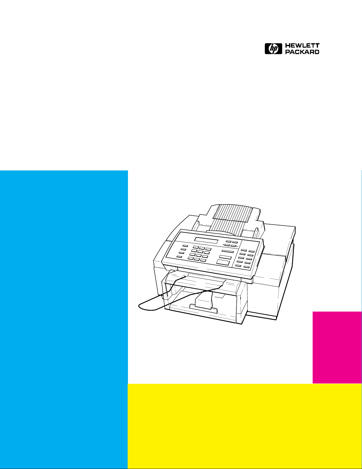
HP OfficeJet Series 300
Printer Fax Copier Scanner
Technical Support Solutions Guide
Model 300
(PrinterFaxCopier Only)
Model 330
Model 350
Page 2

1
Product Information
Subject Page
Introduction 1-2. . . . . . . . . . . . . . . . . . . . . . . . . . . . . . . . . . . . . . . . . . . . . . . . . . . . . . . . . . . . . . . . . . . . . . . . . . . .
Product Description 1-2. . . . . . . . . . . . . . . . . . . . . . . . . . . . . . . . . . . . . . . . . . . . . . . . . . . . . . . . . . . . . . . . . . . . . .
Overview of Product Capabilities 1-3. . . . . . . . . . . . . . . . . . . . . . . . . . . . . . . . . . . . . . . . . . . . . . . . . . . . . . . . . . .
Product Features 1-4. . . . . . . . . . . . . . . . . . . . . . . . . . . . . . . . . . . . . . . . . . . . . . . . . . . . . . . . . . . . . . . . . . . . . . . .
Simultaneous Tasking Features 1-6. . . . . . . . . . . . . . . . . . . . . . . . . . . . . . . . . . . . . . . . . . . . . . . . . . . . . . . . . . . . .
Product Specifications 1-8. . . . . . . . . . . . . . . . . . . . . . . . . . . . . . . . . . . . . . . . . . . . . . . . . . . . . . . . . . . . . . . . . . . .
Print Cartridges 1-11. . . . . . . . . . . . . . . . . . . . . . . . . . . . . . . . . . . . . . . . . . . . . . . . . . . . . . . . . . . . . . . . . . . . . . . . .
Software Programs 1-11. . . . . . . . . . . . . . . . . . . . . . . . . . . . . . . . . . . . . . . . . . . . . . . . . . . . . . . . . . . . . . . . . . . . . . .
Media 1-11. . . . . . . . . . . . . . . . . . . . . . . . . . . . . . . . . . . . . . . . . . . . . . . . . . . . . . . . . . . . . . . . . . . . . . . . . . . . . . . . .
Media Tray Capacities 1-13. . . . . . . . . . . . . . . . . . . . . . . . . . . . . . . . . . . . . . . . . . . . . . . . . . . . . . . . . . . . . . . . . . . .
Media Print Area 1-14. . . . . . . . . . . . . . . . . . . . . . . . . . . . . . . . . . . . . . . . . . . . . . . . . . . . . . . . . . . . . . . . . . . . . . . .
Ordering Information 1-15. . . . . . . . . . . . . . . . . . . . . . . . . . . . . . . . . . . . . . . . . . . . . . . . . . . . . . . . . . . . . . . . . . . . .
Product Information 1-1
Page 3

Introduction
This Technical Support Solutions Guide contains information necessary to support the HP OfficeJet Series 300
Printer/Fax/Copier/Scanner family of products. Although model and country-specific functionality may differ across
the HP OfficeJet product line, the support and service strategy is consistent. The products covered in this guide will be
commonly referred to as the HP OfficeJet Series 300 except where model or country-specific differences are noted.
This guide is divided into six chapters as follows:
D Chapter 1 Product Information
D Chapter 2 Installation and Configuration
D Chapter 3 Routine Maintenance
D Chapter 4 Calibration and Adjustment
D Chapter 5 Problem Resolution
D Chapter 6 Service and Support Information
This Technical Support Solutions Guide is designed to be used with the HP OfficeJet Models 300, 330, and 350 User’s
Guides as a complete technical support reference package. Typical user setup tasks are contained in the User’s Guides
and answers to questions related to such tasks can be found there. Refer to the User’s Guide for your model when
questions about setup, user settings and use are encountered. Refer to this guide for information on troubleshooting
and service and support programs.
Product Description
The HP OfficeJet Model 300 is a plain paper, thermal inkjet printer,facsimile(fax),convenience copier machine. The
HP OfficeJet Models 330 and 350 are plain paper, thermal inkjet printer, facsimile (fax), convenience copier, and
scanner machines. Models 330 and 350 can also fax documents directly from a personal computer (PC) or scan
documents into a PC. The Model 350 includes optical character recognition (OCR) software from Caere. For
answers to questions about the OCR software, contact Caere directly. All members of this series are CCITT/ITU
group 3-ECM compatible. Designed to fit on a desktop, they weigh 9.55 kg (21 lb). HP OfficeJet Series 300 machines
have a full-featured printer, which can be used with your PC and either Windows or DOS drivers. Each has 256 KB of
printer memory and a 16 KB printer buffer. The built-in fax machine feature provides many advanced fax features
including speed dialing capability for 65 stations, with a 10 seconds per page transmission speed and 24 page fax
memory. As a convenience copier, HP OfficeJet Series 300 machines can be set to copy up to 99 copies of an original
at a speed of 50 seconds per page. The Model 330 and 350 versions of the HP OfficeJet Series 300 use Eclipse FAX
SE which provides the ability to send faxes directly from the PC, receive faxes to the PC, and scan images into
PC-based files. HP OfficeJet Series 300 machines also use a management function that allows them to be set up from
the PC using Windows-based menus. All HP OfficeJet Series 300 machines use cut–sheet plain paper (100 sheet
paper tray capacity) and a thermal inkjet cartridge.
R
Product Information1-2
Page 4
SL1
HP OfficeJet Model Series 300 Printer/Fax/Copier/Scanner
Overview of Product Capabilities
The following table provides an overview of HP OfficeJet Series 300 capabilities.
Overview of HP OfficeJet Series 300 Capabilities
Model 300 Model 330 Model 350
Print from a PC
Receive a Fax
Fax from the Automatic
Document Feeder (ADF)
Fax from memory
Copy from the ADF
Print from a PC
Fax from a PC
Receive a fax to a PC
Scan a document to a PC
Scan a document to a PC
with OCR*
Note: The Optical Character Recognition (OCR) package used with the Model 350
is OmniPage Limited Edition.
Product Information 1-3
Page 5

Product Features
The following table lists the features of the HP OfficeJet Series 300 printer/fax/copier/scanner described in this guide.
HP OfficeJet Series 300 Features
Feature Description
Shares a single line with the telephone and a
telephone answering machine (TAM)
Speed dialing A two-digit number represents a telephone number.
Fax settings Settings allow the user or service person to customize
Halftone scanning The ability to interpret shades of gray into dot
Error Correction Mode Detects errors that occur during the transmission of a
Automatic Journals The HP OfficeJet can be set to print a summary sheet
Print from PC functionality Allows printing of print jobs from the personal
Copy functionality Allows for up to 99 copies of an original, includes
Polling and being polled Ability to have a document ready for retrieval by
Sending faxes at deferred times The ability to delay fax transmissions to another
Automatic and fixed print reduction modes Print reduction modes which fit an incoming
Automatic and manual redialing Automatically redials if the line is busy or no
Backup (Out-of-paper, out-of-ink) reception Stores incoming faxes and print jobs in memory if
Remote diagnostics Allows remote access to all user settings and
Sending to multiple fax numbers The ability to send a document to multiple (up to 10)
(Continued on next page)
Answering machine answers all calls. While your
greeting plays, the HP OfficeJet listens for a fax tone.
If fax tone is detected, the HP OfficeJet takes the call.
Provides quick and easy dialing for up to 60 locations and 5 groups of numbers.
the fax for specific needs.
patterns to produce an appearance of gray in an
image. Improves the image quality of photographs.
document and automatically requests resending of
the erroneous portion.
of each transaction or polling operation, to print a
journal of the last 30 transactions, print a record of
the speed dial numbers stored in memory, print a
menu structure diagram with current settings and to
print self-test and demo reports.
computer, when using appropriate printer driver.
copy reduction.
another fax station and to call other fax stations to
retrieve information.
station until a user-set time is reached.
document onto a given paper size.
answer; retains the last number dialed. Redials up to
5 times at 5 minute intervals.
out of paper or ink, or paper or ink is not installed.
machine parameters.
fax numbers.
Product Information1-4
Page 6

HP OfficeJet Features (Continued)
Feature Description
Memory reception capacity Depending upon amount of information on pages
sent, memory allows for up to 24 page storage.
One-touch feature Ten programmable one-touch keys are provided for
easier, speedier faxing.
Fax to/from PC functionality
(HP OfficeJet Models 330 and 350 only, using the
Eclipse FAX SE software program provided)
The ability to send and receive faxes from the PC
using Eclipse FAX SE functionality. Faxes can be
sent directly from the PC without printing them and
faxes can be received either to paper or to the PC
The Model 300 can receive and print a fax sent from
where they can be viewed, filed or printed.
a remote PC over the telephone line, but it cannot
receive and upload a fax to a local PC.
HP OfficeJet Series 300 Manager Allows the user to setup and monitor the status of the
HP OfficeJet from the PC using Windows-based me-
nus.
Convenience Scanning
(HP OfficeJet Models 330 and 350 only)
Provides a convenience scanner to scan images into
PC-based files.
Software Programs Windows and DOS printer drivers, a scanner driver
and printer fonts are provided.
Product Information 1-5
Page 7

Simultaneous Tasking Features
If HP OfficeJet
The HP OfficeJet Series 300 is capable of performing several tasks at the same time. Use the following chart as a
reference of which tasks can be performed simultaneously. Attempting to perform concurrent tasks not supported
may result in a display message or error condition.
Can I?
Series 300 is ...
Send
a print job
Receive
a paper fax
All HP OfficeJet Series 300s HP OfficeJet 330 and 350
Printing
a PC file
Printing
a paper fax
Receiving
a paper fax
Sending
a paper fax
Copying Yes
Receiving
a PC fax
Sending
a PC fax
Scanning Yes Yes No
Yes
prints when
first print
job ends
Yes
prints when
fax printing
ends
Yes
prints when
fax printing
ends
Yes No
prints when
copying ends
Yes No
Yes No
Yes
prints when
PC print
job ends
Yes
prints when
first print
job ends
No
phone line is
being used
phone line is
being used
Yes
prints when
copying ends
phone line is
being used
phone line is
being used
Send
a paper fax
Yes Yes Yes Yes
Yes Yes Yes Yes
No
phone line is
being used
No
phone line is
being used
No
ADF is
being used
No
phone line is
being used
No
phone line is
being used
ADF is
being used
Receive
a PC fax
No
phone line is
being used
No
phone line is
being used
Yes Yes No
No
phone line is
being used
No
phone line is
being used
Yes Yes No
Send
a PC fax
Yes (with
delay) sent
as soon as
first fax is
complete
Yes (with
delay) sent
as soon as
first fax is
complete
Yes (with
delay) sent
as soon as
first fax is
complete
Yes (with
delay) sent
as soon as
first fax is
complete
Scan
to the PC
Yes
No
ADF is
being used
ADF is
being used
Yes
Yes
ADF is
being used
Product Information1-6
Page 8

The following task combinations can be performed simultaneously.
1. An incoming fax will be stored in memory while:
faxes in memory are printing
a local copy is printing
a print job is printing
a report is printing
2. A fax can be sent from the automatic document feeder while:
faxes in memory are printing
a print job is printing
a report is printing
3. Print jobs can be printed while:
a fax is being sent from the automatic document feeder
a delayed send fax from memory is being sent
a delayed send fax from the automatic document feeder is being sent
a broadcast fax from memory is being sent
a document is polled from the automatic document feeder
4. A delayed send fax from memory can be sent while:
a print job is printing
5. A broadcast fax from memory can be sent while:
a print job is printing
6. A delayed send fax from the automatic document feeder can be sent while:
a print job is printing
7. Remote fax machines can poll the HP OfficeJet Series 300 machine while:
faxes in memory are printing
a print job is printing
a report is printing
8. Faxes in memory can be printed while:
an incoming fax is stored in memory (and takes over the display)
Product Information 1-7
Page 9

Product Specifications
Review the following table for product specifications of the HP OfficeJet Series 300 machines.
HP OfficeJet Series 300 Specifications
Function Specification Description
Overall Specifications Dimensions 17.25 w x 15.5 d x 11.125 h (inches)
438 w x 394 d x 283 h (mm)
Weight 19.5 lb (8.85 kg)
Power Source (autoranging) 100-240 Vac, 1.0 A, 50-60 Hz
Power Consumption 10 watts at idle, 45 watts maximum
Operating Environment Temperature range for best print quality:
15°C (59°F) to 35°C (95°F)
Allowable temperature/humidity range: 5°C
(41°F) to 40°C (104°F), 15-80% RH non-
condensing
Maximum noise level generated:
Sound Power, LwAd = 6.4 B(A)
Sound Pressure, LpAm = 50 dB(A)
Printer Specifications Print Method Plain paper drop-on-demand thermal inkjet
Printer Memory 16 KB printer buffer
Printer Command Language HP PCL Level 3
Printer Interface Parallel (Bi-Centronics)
Resolution
(dots per inch = dpi)
Print Speed
(page(s) per minute = ppm)
Windows:
Presentation mode = 600 x 300 dpi with
REt
Normal mode = 600 x 300 dpi with RE
Fast mode = 300 dpi
DOS (text):
Letter quality = 600 x 300 dpi with RE
Draft quality = 300 dpi with ink reduction
Windows print speed:
Presentation mode = 1 ppm
Normal mode = 2.5 ppm
Fast mode = 3 ppm
DOS print speed:
(characters per second = cps
(characters per inch = cpi)
Paper Sizes U.S. letter = 8.5 x 11 in.
Product Information1-8
Letter quality = 167 cps at 10 cpi
Draft quality = 240 cps at 10 cpi
U.S. legal = 8.5 x 14 in.
European A4 = 210 x 297 mm
Executive = 7.25 x 10.5 in
U.S. No. 10 envelope = 4.12 x 9.5 in
European DL envelope = 220 x 110 mm
U.S. transparency = 8.5 x 11 in.
European A4 transparency = 210x297 mm
Page 10

Function Specification Description
Printer Specifications
(continued)
HP OfficeJet Series 300 Specifications (continued)
Internal Fonts Courier (Portrait Orientation):
Pitch: 5, 10, 16.67, 20 cpi
Point size: 6, 12 pt.
CG Times (Portrait Orientation):
Pitch: Proportional
Point size: 5, 6, 7, 8, 10, 12, 14 pt.
Letter Gothic (Portrait Orientation):
Pitch: 6, 12, 24 cpi
Point size: 6, 12 pt.
Univers (Portrait Orientation):
Pitch: Proportional
Point size: 5, 6, 7, 8, 10, 12, 14 pt.
Courier (Landscape Orientation):
Pitch: 10, 16.67, 20 cpi
Point size: 6, 12, 24 pt.
Letter Gothic (Landscape Orientation):
Point and Pitch: 6, 12, 24 pt for 12, 24 cpi;
4.75, 9.5, 19 pt for 16.67 cpi
Character Set Support PC-8, HP Roman 8, PC-8
Danish/Nor, UK ISO 4, German ISO 21,
French ISO 69, Italian ISO 15, Nor v.1 ISO
60, Swed Names ISO 11, Spanish ISO 17,
ASCII, Portug ISO 16, PC-850, ECMA-94
Latin 1, HP Legal
Printing Margins
(These numbers represent the
maximum printable area for this
device. However, your printer
driver may create a smaller
printable area.)
U.S. letter-size paper:
Top margin = 1.0 mm 〈± 1.0 mm)
Bottom margin = 10.9 mm (± 0.6 mm)
Left margin = 6.4 mm (± 1.0 mm)
Right margin = 6.4 mm (± 1.0 mm)
European A4-size paper:
Top margin = 1.0 mm 〈± 1.0 mm)
Bottom margin = 10.9 mm (± 0.6 mm)
Left margin = 3.4 mm (± 1.0 mm)
Right margin = 3.4 mm (± 1.0 mm)
Vertical Alignment ±0.002 in.
Scalable TrueTypet Fonts
for MicrosoftE Windows
Arial Black, CG Goudy Old Style,
Phyllis, Graphite Light, CG Poster
Bodoni, Lucida
Casual, Gill Sans
Shadow, Milestone Font, Signet
Roundhand, and PL Benguiat Frisky
Product Information 1-9
Page 11

HP OfficeJet Series 300 Specifications (continued)
Function Specification Description
Printer Specifications
(continued)
Software Compatibility Microsoft Windows 3.1
Microsoft Windows 95
MS Word for Windows (6.0 and above)
WordPerfect for Windows (6.0a and above)
WordPro (Ami Pro) for Windows
(3.0 and above)
MS Excel for Windows (5.0)
Lotus 1-2-3 for Windows (4.0 and above)
Also compatible with DOS application
HP DeskJet 520
Fax Specifications Coding Schemes MH, MR, MMR
Compatibility CCITT/ITU Group 3
Distinctive Ring Detect Yes
Image Memory 24 pages (CCITT/ITU chart #1, about
400 kB)
Modem Speed 9600, 7200, 4800 and 2400 bits per second
Paper Sizes U.S. letter = 8.5 x 11 in.
U.S. legal = 8.5 x 14 in.
European A4 = 210 x 297 mm
Paper Weight (faxes sent) 16 to 24 lb (60 to 90 g/m2)
Scan Margins (faxes sent) Top margin = 3.0 mm ± 3.0 mm
Bottom margin = 0.0 mm ± 4.0 mm
Center line = 0.0 mm ± 2.5 mm
Width = 216.2 mm ± 2.6 mm
Scan Resolution Standard = 203 x 98 dpi
Fine = 203 x 196 dpi
Photo = 203 x 196 dpi (dithered)
Scan Width Maximum = 8.5 inches (216 mm)
Speed Dialing 60 locations and 5 groups
One-Touch Dialing 10 of the 60 Speed Dial locations
Transmission Speed 10 seconds per page
(CCITT/ITU chart #1 using ECM)
Reception Speed 20 seconds per page
(CCITT/ITU chart #1 using ECM)
Copier Specifications Copy Speed 50 seconds per page
Copier Resolution Fine or Standard = 300 x 300 dpi (Bi-level)
Photo = 300 x 300 dpi (grayscale)
Paper Sizes U.S. letter = 8.5 x 11 in.
U.S. legal = 8.5 x 14 in.
European A4 = 210 x 297 mm
Multiple Copies Up to 99 (per full paper tray)
Copy Reduction 100%, 95%, 90%, 85%, 80%,
75% (Legal-to-Letter), 70%
Product Information1-10
Page 12

HP OfficeJet Series 300 Specifications (continued)
Function Specification Description
Copier Specifications
(Continued)
PC Scan
Specifications
Scan Margins Top margin = 3.0 mm ± 3.0 mm
Bottom margin = 2.0 mm ± 3.0 mm
Left: U.S. letter = 0.0 mm ± 3.0 mm
A4 = 0.0 mm ± 0.0 mm
Right: U.S. letter = 0.0 mm ± 3.0 mm
A4 = 0.0 mm ± 0.0 mm
Width = 216.2 mm ± 2.6 mm12
Scan Width Maximum = 8.5 inches (216 mm)
Current Connectivity TWAIN 1.6 Interface
Scan Resolution Software Determined
203 x 196 dpi
or 300 x 196 dpi
Print Cartridges
The HP OfficeJet uses one high–capacity black print cartridge, HP part number 51626A.
When printing text only on letter-size media, ink lasts, on average, about 1000 pages. Text used was CCITT/ITU test
image number 1, the Slerexe Company letter. If text of greater density is printed or quality mode is used, results may
vary considerably. Ink cartridge longevity is also affected by larger paper sizes containing more printed matter or
photos or illustrations. If the ink lasts much less than 1000 pages, ensure that you have removed both pieces of tape
from the print cartridge before beginning to use it, and that the conductive part of the cartridge surface is clean.
Software Programs
Several software programs and drivers are provided. The Eclipse FAX SE is provided and used with Models 330 and
350. The HP OfficeJet Series 300 Manager programs and Windows drivers are provided with all models.
Eclipse FAX SE allows the user to send high-quality faxes directly from the PC, receive faxes to the PC,
and scan images into PC-based files.
HP OfficeJet Series 300 Manager lets the user setup the HP OfficeJet Series 300 from the PC, using
Windows-based menus, rather than the device’s front panel. The Manager also serves as a status monitor,
displaying information and error messages. It also tells the user whether or not the HP OfficeJet Series
300 is properly connected.
Windows drivers are provided. A DOS driver is provided with many applications, but one may be ordered
separately from Hewlett Packard. See “Ordering Information” later in this chapter for information on how
to order the DOS driver.
Media
An HP OfficeJet Series 300 works with ordinary bond and photocopy papers. Paper properties are subject to change by
paper manufacturers, and Hewlett-Packard has no control over such changes. For optimum print quality, test paper
(printing on both sides) for suitability, before you purchase large quantities.
Use plain bond or white photocopy paper of high quality. It should be free of:
Carbon Loose Particles
Cuts or tears Dust
Grease spots Curled, bent or frayed edges
Product Information 1-11
Page 13

Colored bond and photocopy paper (such as pink, yellow, or blue) can be used, as long as it meets these specifications:
D Paper Size U.S. letter 8 1/2 in x 11 in, (216 x 279 mm)
U.S. legal 8 1/2 in x 14 in, (215 x 356 mm)
Executive 7.25 x 10.5 in, (184 mm x 267 mm)
A4 metric 8.27 x 11.7 in, (210 mm x 297 mm)
D Envelope Size U.S. No. 10 4.12 x 9.5 in, (105 x 241 mm)
European DL 8.66 x 4.33 in, (220 x 110 mm)
D Paper Type Cut sheet
D Cut Edge Conditions Sharp blade cut, with no visible fray
D Finishing Dimensions ± 0.0313 inch of nominal, corners 90_± 0.20_
D Paper Grain Long grain
D Moisture Content 4% to 6% by weight
D Opacity 84% minimum
D Packaging Polylaminated moisture-proof ream wrap
D Paper weight 60 to 135 g/m
2 (
16 lb to 36 lb), 75 g/m
2 (
20 lb) recommended
D Wax Pick 2 inch minimum (Dennison)
When loading paper, observe the following precautions:
D Handle all paper by the edges only
D Load all paper types the same way
D Use only one paper type in the printer’s paper tray at a time
D Always load paper print side up in the media tray
Plain paper has a print side which is not visible to the naked eye, so before removing paper from its package for use in
the printer, check the outside package label. Always load the paper into the machine with the print side facing down.
The print side will be indicated by an arrow or other symbol on the label.
Avoid the following types of media:
D Paper greater than 135 g/m
2
(36 lb) or less than 60 g/m
2
(16 lb)
D Paper with cutouts or perforations
D Multiple part forms
D Carbon copy forms
D Paper sizes other than those listed in this document
Product Information1-12
Page 14

Media Tray Capacities
Sheet capacity for the various paper tray is as follows:
Access door assembly (automatic document feed tray for faxes to be sent)
2
= 20 pages (paper weight ≤ 20 lb or 75 g/m
)
Minimum paper width = 6 in. (152 mm)
Maximum paper width = 8.5 in. (216 mm)
Maximum paper length = 17 in. (432 mm)
2
Input Tray = 100 sheets at a paper weight ≤ 20 lb (75 g/m
) or 20 envelopes (U.S. No. 10 or European
DL)
2
Output tray = 100 sheets at a paper weight ≤ 20 lb (75 g/m
)
Product Information 1-13
Page 15
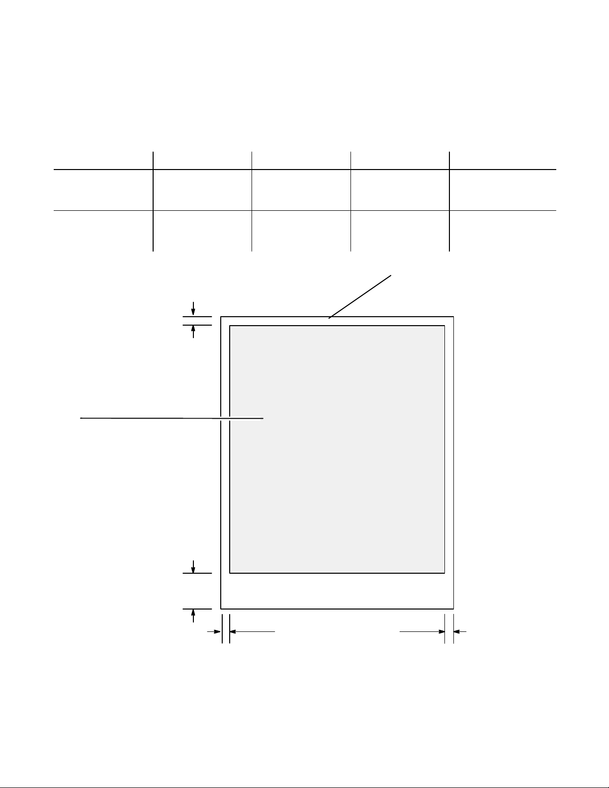
Media Print Area
Maximum printable area for the HP OfficeJet is dependent upon the media size being used. The printable areas for the
media sizes are shown in the following diagram. Data on the minimum margins that can be set effectively and the
amount of variation in those margins is shown in the table above the diagram. The minimum margins are also shown
on the diagram.
Paper Size Left Margin
U.S. Letter
8.5 x 11 in.
0.25 in. ± 0.04 in.
(6.4 mm ± 1.0 mm)
(215 x 279 mm)
European A4
210 x 297 mm
3.4 mm ± 1.0 mm
(0.13 in. ± 0.04 in.)
(8.27 x 11.7 in.)
1.0 mm
(0.04 in.)
Printable area
Letter: 8.0 by 10.5 in.
(203 by 267 mm)
Right Margin Top Margin Bottom Margin
0.25 in. ± 0.04 in.
(6.4 mm ± 1.0 mm)
3.4 mm ± 1.0 mm
(0.13 in. ± 0.04 in.)
0.04 in. ± 0.04 in.
(1.0 mm ± 1.0 mm)
1.0 mm ± 1.0 mm
(0.04 in. ± 0.04 in.)
Paper Size:
U.S. Letter 8.5 x 11 in. (215 x 279 mm)
U.S. Legal 11 x 14 in. (279 x 356 mm)
European A4 210 x 297 mm (8.27 x 11.7 in.)
0.42 in. ± 0.02 in.
(10.9 mm ± 0.06 mm)
10.9 mm ± 0.06 mm
(0.42 in. ± 0.02 in.)
Legal: 8.0 by 13.5 in.
(203 by 343 mm)
A4 198 by 284 mm
(7.8 by 11.2 in.)
10.9 mm
(0.42 in.)
U.S. = 0.25 in. (6.4 mm)
A4 = 3.4 mm (0.13 in.)
Maximum Media Print Area
U.S. = 0.25 in. (6.4 mm)
A4 = 3.4 mm (0.13 in.)
Product Information1-14
Page 16

Ordering Information
Information on ordering exchange units under the HP Exchange program is provided with the program information in
Chapter 6 of this manual.
To order the supplies and accessories listed in the table below, contact your HP dealer. If your dealer is out of stock,
you can order directly from HP for fast shipping service:
Within the U.S.: Call 1-800-538-8787 for all supplies/accessories except documents.
Call 1-800-227-8164 to order user’s guides and technical reference guides.
Outside the U.S.: For phone numbers and addresses of contacts in Australia, Europe, China, India and Korea,
refer to the appropriate Product Support table in Chapter 6. The various countries have
different organizations to contact for support.
Availability, technical information and items shipped with the HP OfficeJet are subject to change without notice.
Ordering Information
Supply/Accessory HP Reorder Part Number
Centronics Parallel Interface Cable (shielded) HP C2950A (2 meter), or HP C2951A (3 meter)
High Capacity InkJet Print Cartridge 51626A
Media
HP Premium Transparency Film (U.S. Letter)
HP Premium Transparency Film (European A4)
HP Premium Glossy Paper (U.S. Letter)
HP Premium Glossy Paper (European A4)
HP OfficeJet and HP OfficeJet Series 300 User’s
Guides
United States (English)
Australia (English)
France (French)
German (German)
Netherlands (Dutch)
United Kingdom (English)
India (English)
Korea (Hungu)
China (Chinese)
HP DeskJet 500 Series Technical Reference Guide C2170-90099
Access Door (see diagram on next page) C2890-60064
Tray Wire (Document Catch) (see diagram on next
page)
Output Tray Assembly (see diagram on next page) C4661-60004
Tray Bridge (see diagram on next page) C4661-40006
Input Tray Assembly (see diagram on next page) C4661-60003
DOS Drivers C2890-10012 (Call HP Driver Distribution Center,
C3834A
C3835A
C3836A
C3837A
Model 300 Model 330 Model 350
C4662-90001 C4661-90001 C4663-90001
C4661-90021
C4661-90003
C4661-90005
C4661-90011
C4661-90000
C4662-90020
C4661-90018
C4662-90016
C4661-80001
Ph (303) 339-7009. Ask for the DOS Driver for HP
OfficeJet.)
Product Information 1-15
Page 17
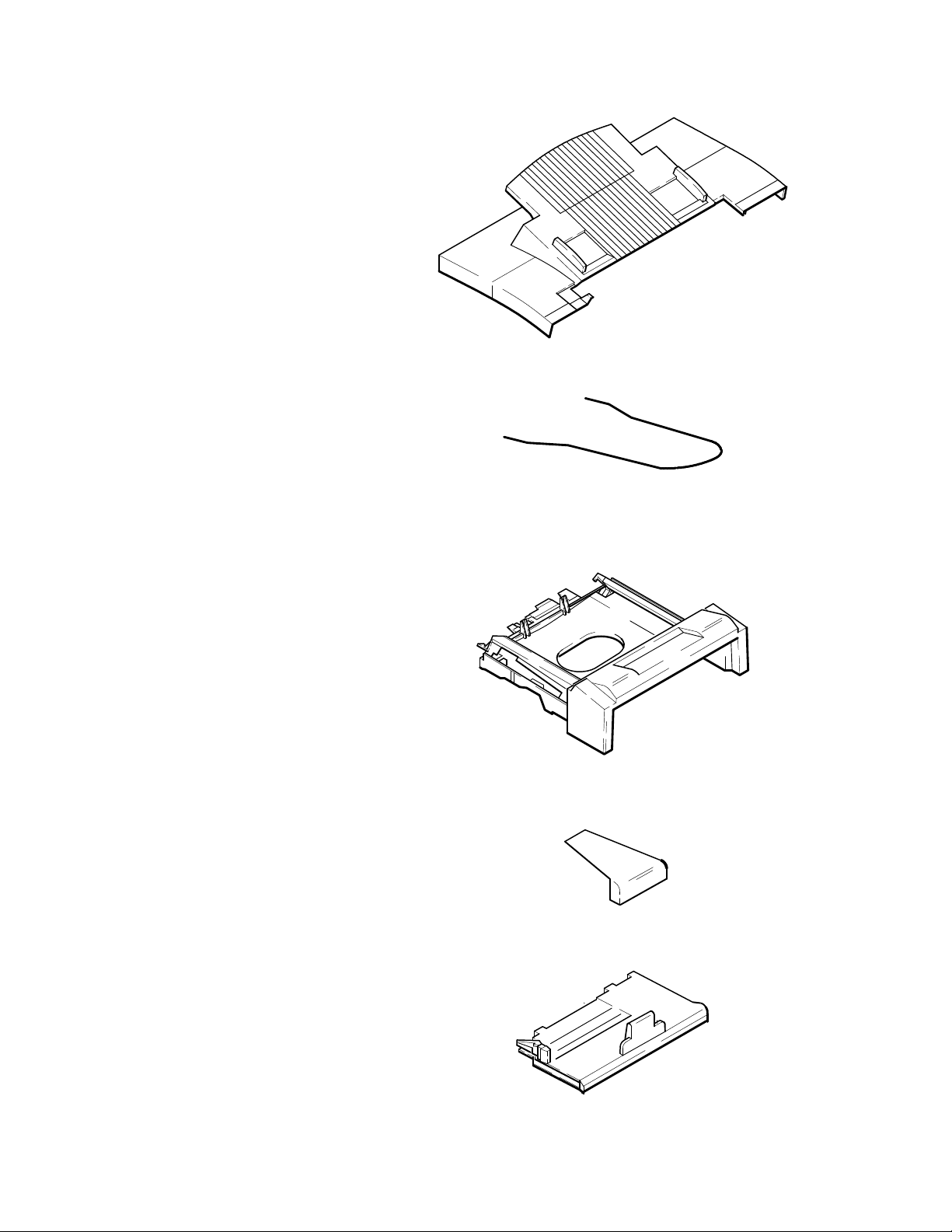
Access Door Assembly
Tray Wire (Document Catch)
Output Tray Assembly
Tray Bridge
Input Tray Assembly
Product Information1-16
Page 18

2
Installation and Configuration
Subject Page
Introduction 2-3. . . . . . . . . . . . . . . . . . . . . . . . . . . . . . . . . . . . . . . . . . . . . . . . . . . . . . . . . . . . . . . . . . . . . . . . . . . .
Using Printer Driver Software 2-3. . . . . . . . . . . . . . . . . . . . . . . . . . . . . . . . . . . . . . . . . . . . . . . . . . . . . . . . . . . . . .
Using Microsoft Windows 3.1 2-4. . . . . . . . . . . . . . . . . . . . . . . . . . . . . . . . . . . . . . . . . . . . . . . . . . . . . . . . . . .
Using Microsoft Windows 95 2-4. . . . . . . . . . . . . . . . . . . . . . . . . . . . . . . . . . . . . . . . . . . . . . . . . . . . . . . . . . .
Using DOS software applications 2-4. . . . . . . . . . . . . . . . . . . . . . . . . . . . . . . . . . . . . . . . . . . . . . . . . . . . . . . .
Hardware and Software Requirements 2-4. . . . . . . . . . . . . . . . . . . . . . . . . . . . . . . . . . . . . . . . . . . . . . . . . . . .
Installing the HP OfficeJet Series 300 Software 2-4. . . . . . . . . . . . . . . . . . . . . . . . . . . . . . . . . . . . . . . . . . . . . . . .
Running the HP OfficeJet Series 300 Manager 2-7. . . . . . . . . . . . . . . . . . . . . . . . . . . . . . . . . . . . . . . . . . . . . . . . .
Running Eclipse FAX SE from the HP OfficeJet Series 300 Manager 2-8. . . . . . . . . . . . . . . . . . . . . . . . . . . . . . .
Changing Parameters and Solving Problems with the OfficeJet Service
Application 2-9. . . . . . . . . . . . . . . . . . . . . . . . . . . . . . . . . . . . . . . . . . . . . . . . . . . . . . . . . . . . . . . . . . . . . . . . . . . . .
Running the Service Application 2-9. . . . . . . . . . . . . . . . . . . . . . . . . . . . . . . . . . . . . . . . . . . . . . . . . . . . . . . .
HP OfficeJet Service Application Characteristics 2-10. . . . . . . . . . . . . . . . . . . . . . . . . . . . . . . . . . . . . . . . . . . .
Changing Parameters 2-11. . . . . . . . . . . . . . . . . . . . . . . . . . . . . . . . . . . . . . . . . . . . . . . . . . . . . . . . . . . . . . . . . .
Printing a Parameter Report 2-12. . . . . . . . . . . . . . . . . . . . . . . . . . . . . . . . . . . . . . . . . . . . . . . . . . . . . . . . . . . .
Setting the Front Panel Language 2-13. . . . . . . . . . . . . . . . . . . . . . . . . . . . . . . . . . . . . . . . . . . . . . . . . . . . . . . .
Setting Remote Service 2-14. . . . . . . . . . . . . . . . . . . . . . . . . . . . . . . . . . . . . . . . . . . . . . . . . . . . . . . . . . . . . . . .
Using Other PC Fax Programs With Models 330 and 350 2-15. . . . . . . . . . . . . . . . . . . . . . . . . . . . . . . . . . . . . . . .
Installing Control Panel and One-Touch Overlays 2-16. . . . . . . . . . . . . . . . . . . . . . . . . . . . . . . . . . . . . . . . . . . . . .
Installing a Print Cartridge 2-17. . . . . . . . . . . . . . . . . . . . . . . . . . . . . . . . . . . . . . . . . . . . . . . . . . . . . . . . . . . . . . . . .
Installing an Interface Cable for Printing 2-18. . . . . . . . . . . . . . . . . . . . . . . . . . . . . . . . . . . . . . . . . . . . . . . . . . . . .
Installing the Power Cord 2-19. . . . . . . . . . . . . . . . . . . . . . . . . . . . . . . . . . . . . . . . . . . . . . . . . . . . . . . . . . . . . . . . .
Installing a Tray Wire 2-19. . . . . . . . . . . . . . . . . . . . . . . . . . . . . . . . . . . . . . . . . . . . . . . . . . . . . . . . . . . . . . . . . . . .
Installing an Access Door Assembly 2-20. . . . . . . . . . . . . . . . . . . . . . . . . . . . . . . . . . . . . . . . . . . . . . . . . . . . . . . . .
Installing an Output Tray 2-20. . . . . . . . . . . . . . . . . . . . . . . . . . . . . . . . . . . . . . . . . . . . . . . . . . . . . . . . . . . . . . . . . .
Installing an Input Tray 2-21. . . . . . . . . . . . . . . . . . . . . . . . . . . . . . . . . . . . . . . . . . . . . . . . . . . . . . . . . . . . . . . . . . .
Loading Paper in the Input (Paper) Tray 2-22. . . . . . . . . . . . . . . . . . . . . . . . . . . . . . . . . . . . . . . . . . . . . . . . . . . . . .
Loading Envelopes in the Input (Paper) Tray 2-23. . . . . . . . . . . . . . . . . . . . . . . . . . . . . . . . . . . . . . . . . . . . . . . . . .
Setting the Paper Size in the Front Panel Menu 2-24. . . . . . . . . . . . . . . . . . . . . . . . . . . . . . . . . . . . . . . . . . . . . . . .
Setting Up for Printing 2-25. . . . . . . . . . . . . . . . . . . . . . . . . . . . . . . . . . . . . . . . . . . . . . . . . . . . . . . . . . . . . . . . . . . .
Setting Up for Faxing (U.S. and Australian Installations) 2-26. . . . . . . . . . . . . . . . . . . . . . . . . . . . . . . . . . . . . . . . .
Receive fax calls only – no voice calls, on a dedicated fax line 2-26. . . . . . . . . . . . . . . . . . . . . . . . . . . . . . . . .
Receive fax and voice calls at the same phone number – without an answering machine 2-27. . . . . . . . . . . . .
Receive fax and voice calls at the same phone number – with an answering machine 2-28. . . . . . . . . . . . . . .
Receive fax and voice calls on the same line with distinctive ring 2-29. . . . . . . . . . . . . . . . . . . . . . . . . . . . . . .
Setting Up for Distinctive Ring 2-30. . . . . . . . . . . . . . . . . . . . . . . . . . . . . . . . . . . . . . . . . . . . . . . . . . . . . . . . . . . . .
Setting the Reception Mode for Incoming Calls 2-31. . . . . . . . . . . . . . . . . . . . . . . . . . . . . . . . . . . . . . . . . . . . . . . .
Setting the Number of Rings to Answer 2-32. . . . . . . . . . . . . . . . . . . . . . . . . . . . . . . . . . . . . . . . . . . . . . . . . . . . . .
Selecting Tone or Pulse Dialing 2-33. . . . . . . . . . . . . . . . . . . . . . . . . . . . . . . . . . . . . . . . . . . . . . . . . . . . . . . . . . . . .
Entering the Date and Time 2-34. . . . . . . . . . . . . . . . . . . . . . . . . . . . . . . . . . . . . . . . . . . . . . . . . . . . . . . . . . . . . . . .
Entering the Header Information (company name and fax number) 2-35. . . . . . . . . . . . . . . . . . . . . . . . . . . . . . . . .
Setting Up for Faxing (U.K. Installation) 2-37. . . . . . . . . . . . . . . . . . . . . . . . . . . . . . . . . . . . . . . . . . . . . . . . . . . . .
Receive fax calls only – no voice calls, on a dedicated fax line 2-38. . . . . . . . . . . . . . . . . . . . . . . . . . . . . . . . .
Receive fax and voice calls at the same phone number – without an answering machine 2-38. . . . . . . . . . . . .
Receive fax and voice calls at the same phone number – with an answering machine 2-39. . . . . . . . . . . . . . .
Setting Up for Faxing (Germany Installation) 2-40. . . . . . . . . . . . . . . . . . . . . . . . . . . . . . . . . . . . . . . . . . . . . . . . . .
Receive fax calls only – no voice calls, on a dedicated fax line 2-41. . . . . . . . . . . . . . . . . . . . . . . . . . . . . . . . .
Installation and Configuration
2-1
Page 19

Subject Page
Setting Up for Faxing (Germany Installation) (Continued)
Receive fax and voice calls at the same phone number – without an answering machine 2-41. . . . . . . . . . . . .
Receive fax and voice calls at the same phone number – with an answering machine 2-42. . . . . . . . . . . . . . .
Setting Up for Faxing (France Installation) 2-43. . . . . . . . . . . . . . . . . . . . . . . . . . . . . . . . . . . . . . . . . . . . . . . . . . . .
Receive fax calls only – no voice calls, on a dedicated fax line 2-44. . . . . . . . . . . . . . . . . . . . . . . . . . . . . . . . .
Receive fax and voice calls at the same phone number – without an answering machine 2-44. . . . . . . . . . . . .
Receive fax and voice calls at the same phone number – with an answering machine 2-45. . . . . . . . . . . . . . .
Setting Up for Faxing (Netherlands Installation) 2-46. . . . . . . . . . . . . . . . . . . . . . . . . . . . . . . . . . . . . . . . . . . . . . .
Receive fax calls only – no voice calls, on a dedicated fax line 2-47. . . . . . . . . . . . . . . . . . . . . . . . . . . . . . . . .
Receive fax and voice calls at the same phone number – without an answering machine 2-47. . . . . . . . . . . . .
Receive fax and voice calls at the same phone number – with an answering machine 2-48. . . . . . . . . . . . . . .
Installation and Configuration
2-2
Page 20

Introduction
In this chapter contains information about installing the software applications provided with HP OfficeJet Series 300,
including the:
Printer Drivers
(including Windows driver software)
HP OfficeJet Series 300 Software
(including the HP OfficeJet Series 300 Manager and Eclipse FAX SE (PC fax applications)
Included is information about installing the:
control panel overlay (if a new one is being installed)
print cartridge
interface cable for printing
power cord
Instructions for installing the following customer orderable and installable parts are provided:
access door assembly
output tray assembly
input tray assembly
tray wire (document catch) (installation is optional)
Also provided is information on how to:
load paper
load envelopes
set the paper size in the menu
set up for printing
set up for faxing
Using Printer Driver Software
Detailed information on each of the software installations and their use is provided in the HP OfficeJet Series 300
User’s Guides. Also, the applications guides provided with each driver will provide specific information for the
installation and use of the software package.
Refer to the options listed below to determine which printer driver the user needs to install to make his computer and
software work with the HP OfficeJet. Printer drivers (also called printer software) are software files that control the
user’s printer and allow his software application to access the printer’s features.
Installation and Configuration
2-3
Page 21

Using Microsoft Windows 3.1
Install the HP OfficeJet Series 300 Printer Software for Microsoft Windows 3.1 provided with the HP OfficeJet Series
300 machine. See the documentation that came with the printer software for installation instructions.
Using Microsoft Windows 95
Ensure that the user has installed the HP OfficeJet Series 300 Printer Software for Microsoft Windows 95 provided
with the HP OfficeJet Series 300 machine. See the documentation that came with the printer software for installation
instructions.
Using DOS software applications
For each DOS software application used, the user must install a specific printer driver. The user’s DOS software
application supplies printer drivers for many printer models. A printer driver that supports printer features may
already be in the software application. A DOS driver disk can also be ordered separately from Hewlett-Packard Driver
Distribution Center. See the section labeled “Ordering Information” in chapter 1of this guide for details on how to
order this disk. Additional information is provided in this section, see Setting Up for Printing.
Hardware and Software Requirements
The following are the minimum computer system requirements:
Parallel port must support bidirectional communication
4 Megabytes (MB) of Random Access Memory (RAM). 8 MB RAM recommended
5 MB hard disk space
Windows 3.1 operating system
Note: To have the customer add the HP OfficeJet Series 300 Manager to the Windows
StartUp group, so that the HP OfficeJet Series 300 Manager will run automatically
whenever Windows is started, make sure that the PC has enough memory to run the
HP OfficeJet Series 300 Manager simultaneously with all the other applications that
will be run. Then, have the customer open the HP OfficeJet Series 300 Manager
and StartUp groups, press the Ctrl key, and click and drag the HP OfficeJet Series
300 Manager icon into the StartUp group.
Installing the HP OfficeJet Series 300 Software
The information provided here will help with the installation of the HP OfficeJet Series 300 Software including the
HP OfficeJet Series 300 Manager and Eclipse FAX SE software applications. Additionally, other PC Fax programs
usable with the HP OfficeJet Series 300 are described. Detailed information on custom installation and usage is
provided in the HP OfficeJet Series 300 User’s Guide for each model.
Installation and Configuration
2-4
Page 22
Use the following instructions when helping the user install the software for the first time in the HP OfficeJet Series
300. Have the user perform the following steps:
1. Check that the HP OfficeJet Series 300 device has been properly set up, and that it is connected to the computer,
turned on, and has paper loaded.
2. Close any open applications, saving files if necessary.
3. Insert Disk 1 of the HP OfficeJet Series 300 software
into the flexible disk drive.
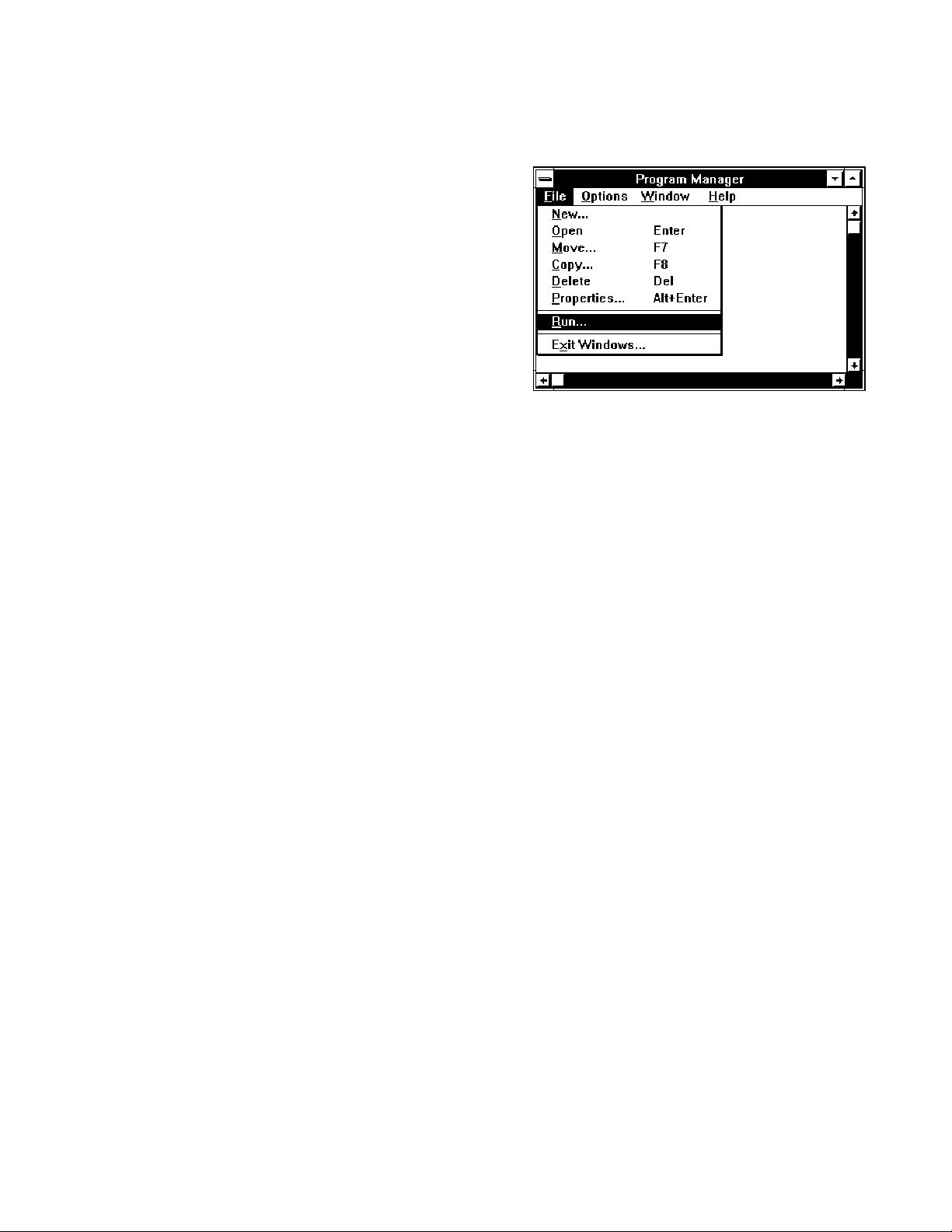
4. From the Windows Program Manager menu bar,
choose File/Run. The Run dialog box appears.
5. In the Command Line box, type one of the following commands, depending on which flexible disk drive is used:
A:SETUP.EXE
or
B:SETUP.EXE.
6. An “initializing” screen appears, followed by a screen that asks the user to select Standard Installation,
Custom Installation, or Uninstall.
We recommend that first-time users choose Standard Installation, which copies all the HP OfficeJet Series 300
software to the hard disk and sets up the device for printing, scanning, and PC faxing. For information about Custom
Installation, see “Performing a Custom Installation” in the HP OfficeJet Series 300 User’s Guide. For information
about the uninstall option, see “Using the Uninstall Option” in the HP OfficeJet Series 300 User’s Guide.
Click the Standard Installation button and then the OK button.
7. A screen appears, allowing the user to specify the directory in which the HP OfficeJet Series 300 software will be
installed. The default directory is C:\HPOJET.
If this is acceptable, click the OK button. If it is not acceptable, follow the instructions on the screen to select a
different directory. Then click the OK button.
8. As installation takes place, screens are displayed that provide “must know” information about the HP OfficeJet
Series 300. Reading these screens will give the user a head start on understanding how his new product works. Be sure
he has read these screens completely before inserting a new installation disk.
9. After all the files have been copied to the hard disk, the setup program tries to communicate with the
HP OfficeJet Series 300.
If the device is properly connected and turned on, a screen appears, giving the name of the port to which the HP
OfficeJet Series 300 is connected. Click the OK button.
10. If the setup program cannot find the HP OfficeJet Series 300, follow the troubleshooting instructions on the screen
to correct the problem. Then click the Retry button. The setup program tries again to communicate with the HP
OfficeJet Series 300. If it succeeds, a screen appears, giving the name of the port to which the HP OfficeJet Series 300
is connected. Click the OK button.
11. The PC Fax Cover Sheet Information dialog box appears. Complete it as directed, pointing and clicking in each
field to fill it in. When finished, click the OK button.
12. The Fax Header dialog box appears. Complete it as directed and click the OK button.
Installation and Configuration
2-5
Page 23
13. The Fax Receive Mode dialog box appears. Complete it as directed and click the OK button.
Á
Á
Á
Á
Á
Á
Á
Á
Á
Á
Á
Á
Á
Á
Á
Á
Á
Á
Á
Á
Á
Á
Á
Á
Á
Á
Á
Á
If This Is the User’s Situation ...
The user has a separate telephone number dedicated to re-
БББББББББББББББББ
ceiving fax calls only (no voice calls).
The user has one telephone number for both voice and fax
calls, and doesn’t have a telephone answering machine.
БББББББББББББББББ
The user has one telephone number for both voice and fax
БББББББББББББББББ
calls, and does have a telephone answering machine.
БББББББББББББББББ
The user has one telephone number for both voice and fax
БББББББББББББББББ
calls, and subscribes to a distinctive ringing service from the
БББББББББББББББББ
telephone company.
Choose This Setting
Auto.
ББББББББББ
Manual.
ББББББББББ
Auto (The “rings to answer” setting
ББББББББББ
of the answering machine must be
ББББББББББ
less than that of the HP OfficeJet.)
Auto, and click the Distinctive Ring
ББББББББББ
button in the Settings box.
ББББББББББ
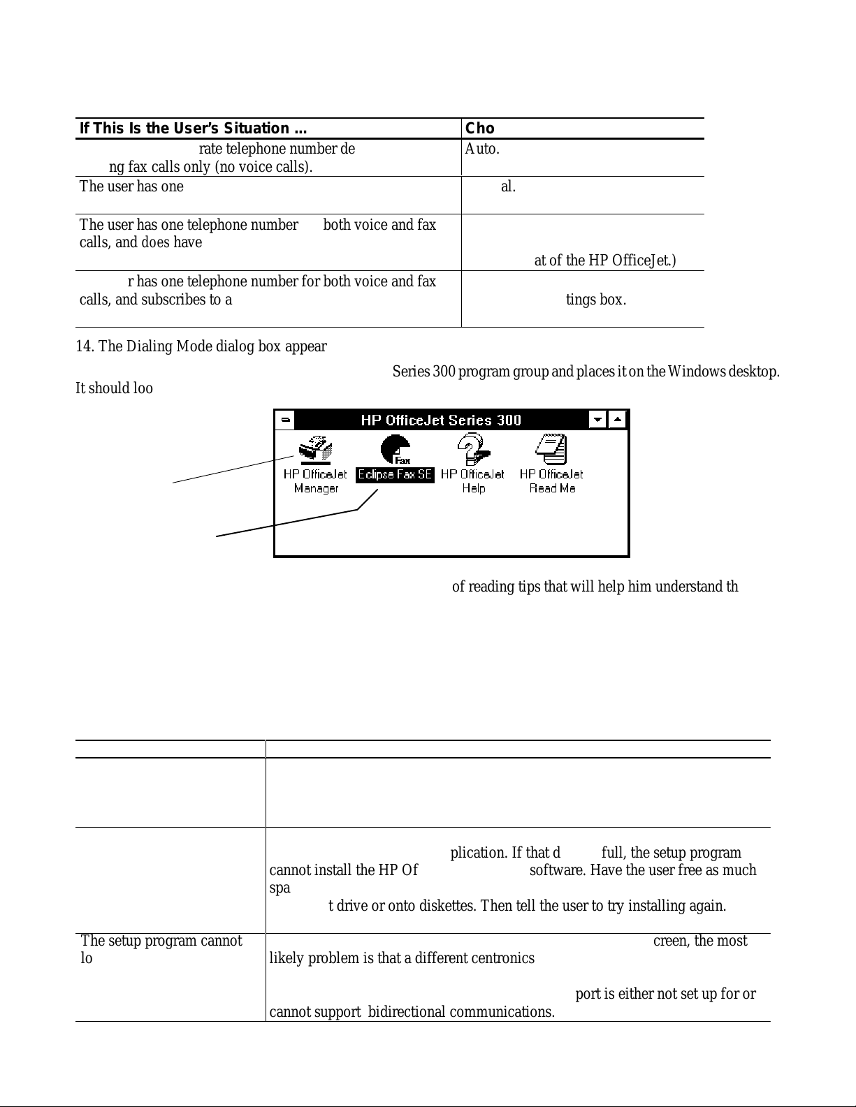
14. The Dialing Mode dialog box appears. Complete it as directed and click the OK button.
15. Next, the setup program creates the HP OfficeJet Series 300 program group and places it on the Windows desktop.
It should look similar to this:
The HP OfficeJet
Manager icon
Not present on the
Model 300
16. As a last step, the setup program gives the user the option of reading tips that will help him understand the basic
functions of the new product.
As the first “tips” screen appears, the HP OfficeJet Series 300 prints a Self Test report. This report shows samples of
new internal fonts, reviews the factory device settings, notifies the user about any print cartridge problems, and
provides product revision information.
Have the user click the Exit button when ready to leave the setup program.
If difficulties arise with the installation, review the following recommendations:
Problem
When reinstalling the software, and the setup program
ББББББББ
says there isn’t enough disk
ББББББББ
space.
The user’s C: drive is full,
so he tried to install the soft-
ББББББББ
ware on his D: drive, but the
ББББББББ
setup program still says he
ББББББББ
don’t have enough disk
ББББББББ
space.
The setup program cannot
locate the HP OfficeJet Se-
ББББББББ
ries 300.
ББББББББ
ББББББББ
Installation and Configuration
2-6
Recommended Action
Use the setup program to uninstall the HP OfficeJet Series 300 software. Then
try installing again.
ББББББББББББББББББББББ
ББББББББББББББББББББББ
The HP OfficeJet Series 300 software requires several files to reside in the drive
that contains the Windows application. If that drive is full, the setup program
ББББББББББББББББББББББ
cannot install the HP OfficeJet Series 300 software. Have the user free as much
ББББББББББББББББББББББ
space on the drive as he can by either deleting unneeded files or moving files to
ББББББББББББББББББББББ
a different drive or onto diskettes. Then tell the user to try installing again.
ББББББББББББББББББББББ
If the user has followed the troubleshooting directions on the screen, the most
likely problem is that a different centronics cable is needed. (About 10% of
ББББББББББББББББББББББ
centronics cables cannot support bidirectional communications.)
ББББББББББББББББББББББ
There is also a chance that user’s PC’s centronics port is either not set up for or
ББББББББББББББББББББББ
cannot support bidirectional communications.
Page 24
Problem
Á
Á
Á
Á
Á
Á
Á
Á
Á
Á
Á
Á
The user is reinstalling the
ББББББББ
software. It ran correctly
ББББББББ
before, but now the setup
program cannot locate the
ББББББББ
Recommended Action
Make sure that the HP OfficeJet Series 300 Manager is not running. Have the
ББББББББББББББББББББББ
user Exit from Windows and then try again. Make sure that (1) the device is
ББББББББББББББББББББББ
properly cabled to the PC, (2) the device is turned on, and (3) the front panel
says “Ready.”
ББББББББББББББББББББББ
device.
The user is trying to
ББББББББ
uninstall the software, but
ББББББББ
the setup program says it
ББББББББ
cannot delete the directory.
Either the directory contains files that do not belong to the HP OfficeJet Series
ББББББББББББББББББББББ
300, or one or more files are open. Ascertain which of these conditions exists
ББББББББББББББББББББББ
by questioning the user. Correct the problem and try again.
ББББББББББББББББББББББ
Running the HP OfficeJet Series 300 Manager
The HP OfficeJet Series 300 Manager is one of two software applications that may be included with the HP OfficeJet
Series 300. The other software application is Eclipse FAX SE (available on the Models 330 and 350, but not on the
Model 300), which lets the user do PC faxing and scanning.
The HP OfficeJet Series 300 Manager allows the user to manage the way that his or her HP OfficeJet Series 300
works. It can be used it to do the following:
Monitor the status of the HP OfficeJet Series 300
Print logs and reports
Change the device settings that were made during installation, and make additional settings that control
faxing, printing, and copying
Note: The HP OfficeJet Series 300 Manager has one other important function: it must
be running in order to use Eclipse FAX SE. It can be either open as a window
or minimized.
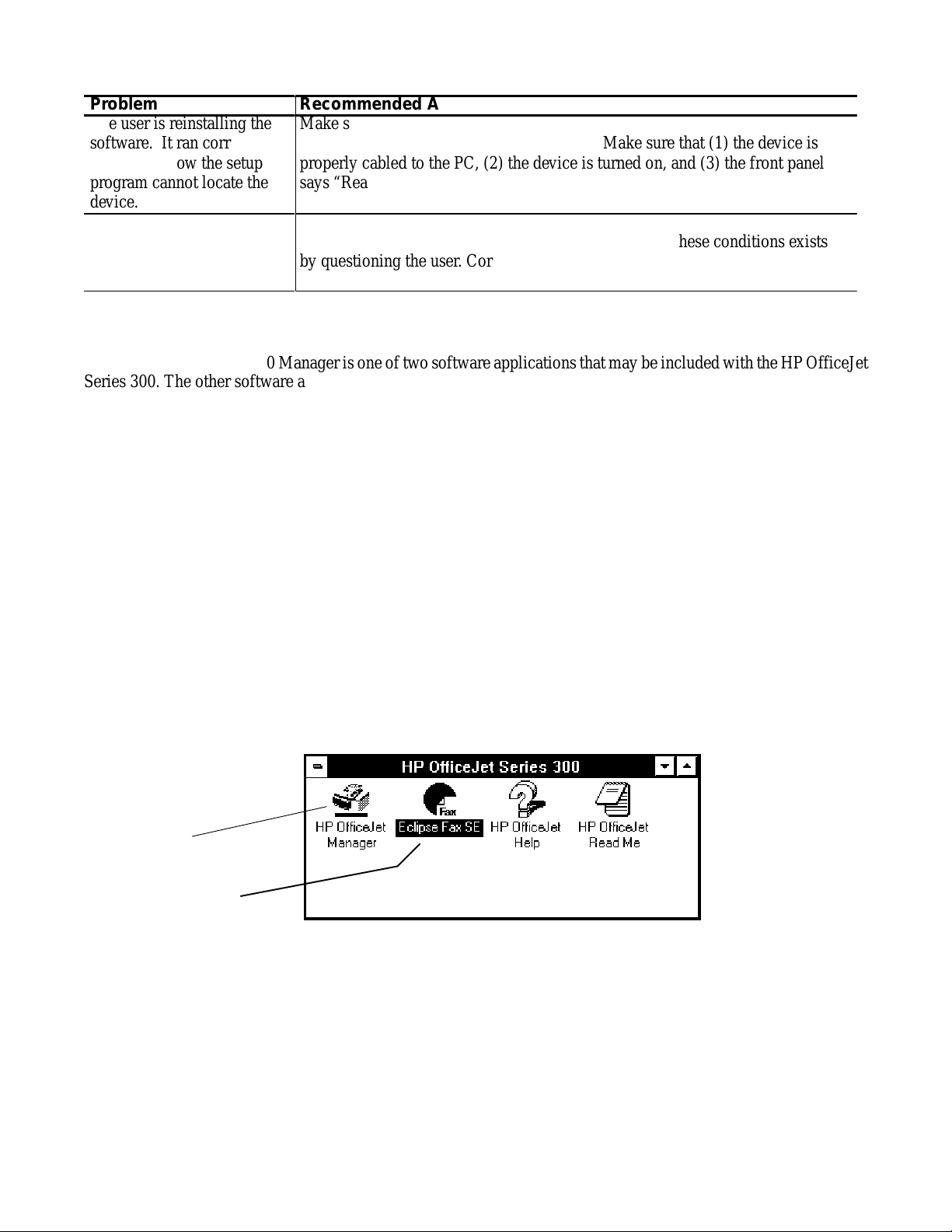
To run the HP OfficeJet Series 300 Manager, the user must double-click the HP OfficeJet Series 300 Manager icon,
which is placed in the HP OfficeJet Series 300 group during installation. The HP OfficeJet Series 300 Manager
window appears.
The HP OfficeJet
Manager icon
Not present on the
Model 300
The user can minimize or close the HP OfficeJet Series 300 Manager as he would any other Windows application.
Remember that when this application is closed, the user can make copies, print, and send and receive paper faxes, but
cannot use Eclipse FAX SE to send and receive PC faxes or do PC scanning. (If the user has a Model 300, the Eclipse
FAX SE is not available.)
Detailed information on use of the Manager is provided in the HP OfficeJet Series 300 User’s Guide.
Installation and Configuration
2-7
Page 25
Running Eclipse FAX SE from the HP OfficeJet Series 300 Manager
The HP OfficeJet Series 300 Models 330 and 350 include a software application, Eclipse FAX SE, that allows the user
to send and receive faxes directly to his or her PC, rather than to the device itself, and to do PC scanning.
Note: Eclipse FAX SE is a separate application from the HP OfficeJet Series 300
Manager, and is not available in the Model 300. Some of the settings that can be
made with the HP OfficeJet Series 300 Manager affect PC faxing. In addition,
the HP OfficeJet Series 300 Manager must be running in order to use Eclipse
FAX SE. It can be either open as a window or minimized.
There may be times when the user wants to run Eclipse FAX SE directly from the HP OfficeJet Series 300 Manager.
To do so, from the HP OfficeJet Series 300 Manager menu bar, have the user choose File/Run Eclipse FAX SE.
Eclipse FAX SE makes it possible for the user to do the following:
Set up to six phonebooks (lists of names and fax numbers) for use with PC faxes. (Phonebooks are
similar to the Speed Dial entries that are used for paper faxing.)
Create a document in any Windows application and then fax it directly from the PC
Receive faxes directly to the PC. Once an incoming fax has been received, the user can use Eclipse FAX
SE to view, print, and delete it
Forward a fax that has been received to another recipient
Fax a document to a file in order to use it later as a fax document
Scan a document into the PC to be sent as a fax, saved as a file, or printed
Add text and images to the faxes
Modify cover pages and include a letterhead and previously created second sheets with faxes.
Send two or more documents as a fax.
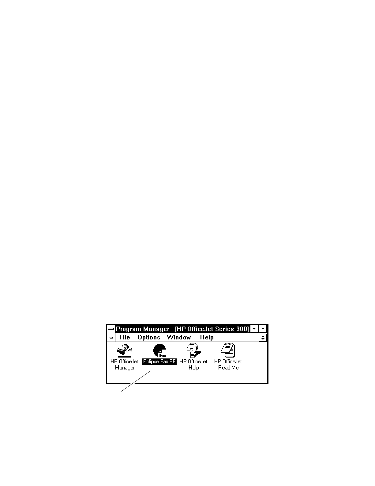
There are three ways to run Eclipse FAX SE.
1. In the HP OfficeJet Series 300 Manager menu bar, choose File/Run Eclipse FAX SE
2. Double-click the Eclipse FAX SE icon in the HP OfficeJet Series 300 program window.
The Eclipse FAX SE icon (not available in the Model 300)
The Eclipse FAX SE window appears. Note the menu bar across the top of the window. For additional information on
using the Eclipse FAX SE application, refer to the HP OfficeJet Series 300 User’s Guide for the user’s model.
3. Click the Fax or Scan button in the AutoPrompt window.
Detailed information on use of the Eclipse FAX SE is provided in the HP OfficeJet Series 300 User’s Guide.
Installation and Configuration
2-8
Page 26
Changing Parameters and Solving Problems with the OfficeJet Service
Application
With assistance from a service representative, the OfficeJet Service Application is a program that allows the user to
easily change OfficeJet parameters from the PC. The service representative will use this tool to diagnose OfficeJet
problems by suggesting parameter changes. The user will key in the changes, and further testing will indicate whether
or not the problem is solved.
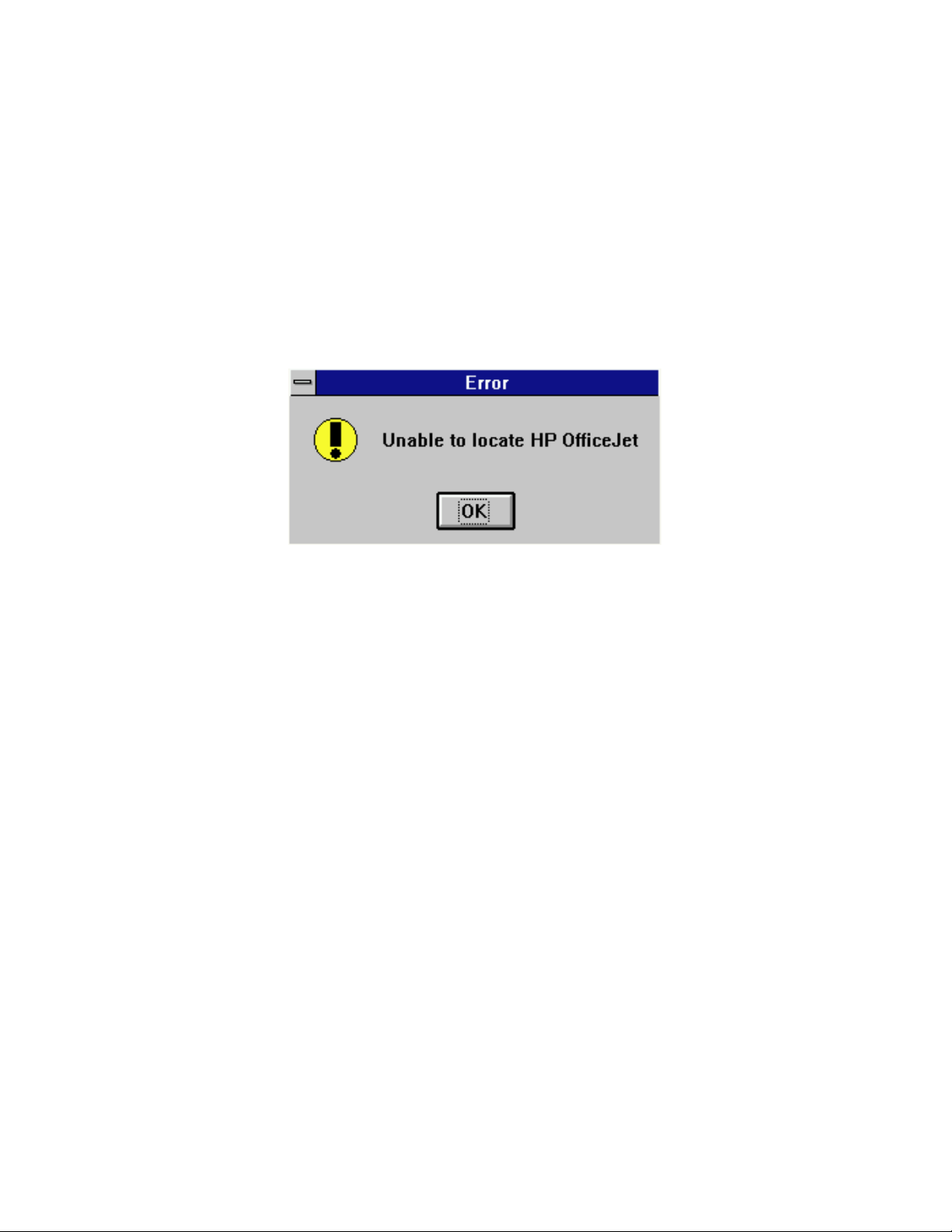
Running the Service Application
Ensure the the HP OfficeJet is connected and powered on. If the HP OfficeJet is not connected and powered on, your
attempt to run the service application will produce the following error message:
Windows 3.1 system: To run the Service Application, perform the following steps.
1. From the Program Manager, choose File, then Run.
2. Type the pathname: c:\hpojet\mgr\service.exe. The executable filename that you must run is service.exe.
Note: The actual pathname may differ from c:\hpojet\mgr\service.exe after a
custom installation. However, the service.exe file will always be in the
same directory as the OfficeJet Manager.
3. Click OK. The window that will appear is shown on the next page of this guide.
Windows 95 system: To run the Service Application, perform the following steps.
1. Click on Start. Then choose Run.
2. Type the pathname: c:\hpojet\mgr\service.exe. The executable filename that you must run is service.exe.
Note: The actual pathname may differ from c:\hpojet\mgr\service.exe after a
custom installation. However, the service.exe file will always be in the
same directory as the OfficeJet Manager.
3. Click OK. The window that will appear is shown on the next page of this guide.
Installation and Configuration
2-9
Page 27
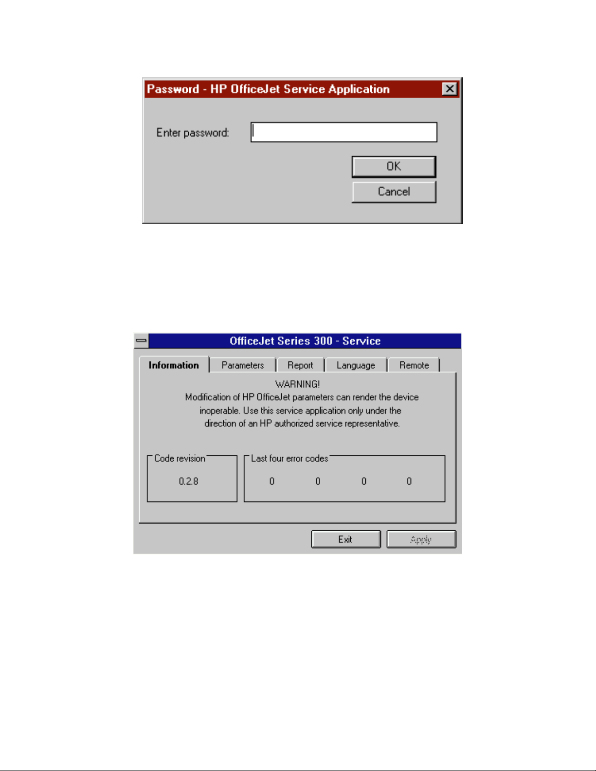
The following window will appear:
To access the HP OfficeJet Service Application, type the password solo. Then click OK. There will be a delay of
approximately 5 to 12 seconds before the HP OfficeJet Series 300 service application appears on the screen.
HP OfficeJet Service Application Characteristics
When the HP OfficeJet Service Application is up and running, its window will appear as follows:
Note: The “Code revision” number or “Last four error codes” numbers may differ
from those shown.
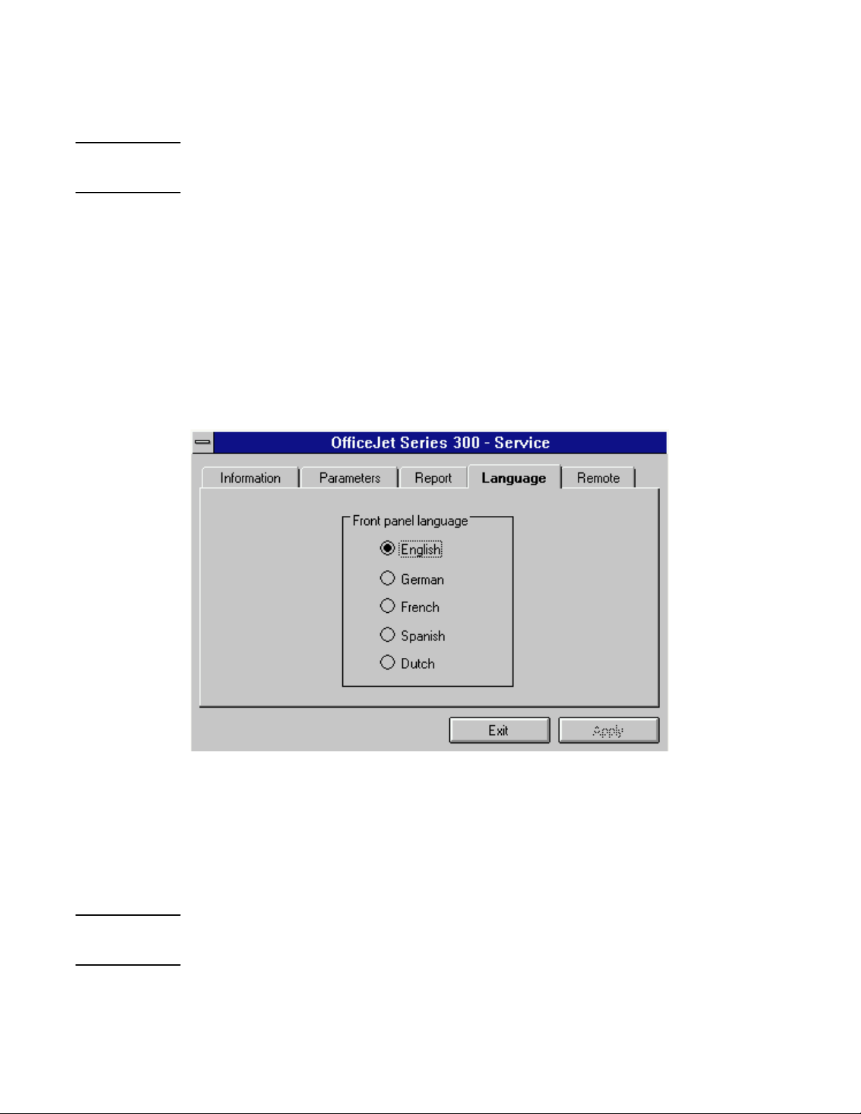
The OfficeJet Service Application contains five tab windows. They are:
Information Displays the code revision and the last four system error codes
Parameters Used to change HP OfficeJet Parameters
Report Used to print an HP OfficeJet Parameter Report
Language Used to set the HP OfficeJet front panel language
Remote Used to set the Remote Service ON or OFF
Installation and Configuration
2-10
Page 28
Click on the tab (Information, Parameters, Report, Language, or Remote to move between windows.
The Apply button applies the selected parameter, language, or remote setting to the HP OfficeJet.
Exiting the Service Application
Whenever exiting the Service Application Program, allow 5 to 10 seconds for the hardware to
terminate the factory and service capability.
To exit or quit the program, click on the Exit button. After depressing the Exit button, be sure to wait 5 to 10 seconds
for the hardware to terminate the factory and service capability before taking any other action. During the transition
observe the HP OfficeJet front panel LCD display for the following events:
The phrase “Enter header number” appears on the top line of the HP OfficeJet LCD display.
A string of characters appears on the bottom line of the HP OfficeJet LCD display.
The HP OfficeJet LCD display blanks out briefly and returns to the normal “ready” state
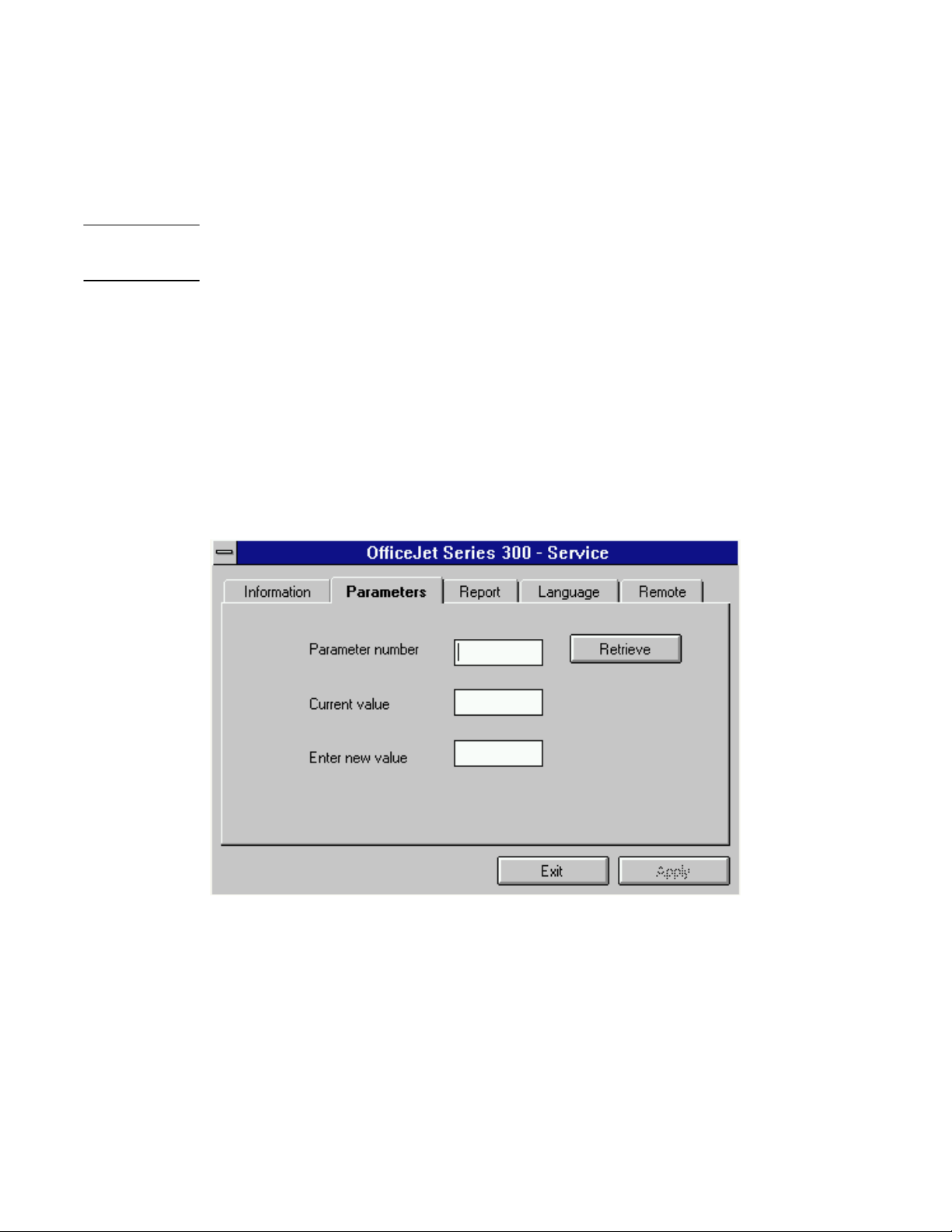
Changing Parameters
Clicking on the “Parameters” tab in the service application main menu causes the window to appear as follows:
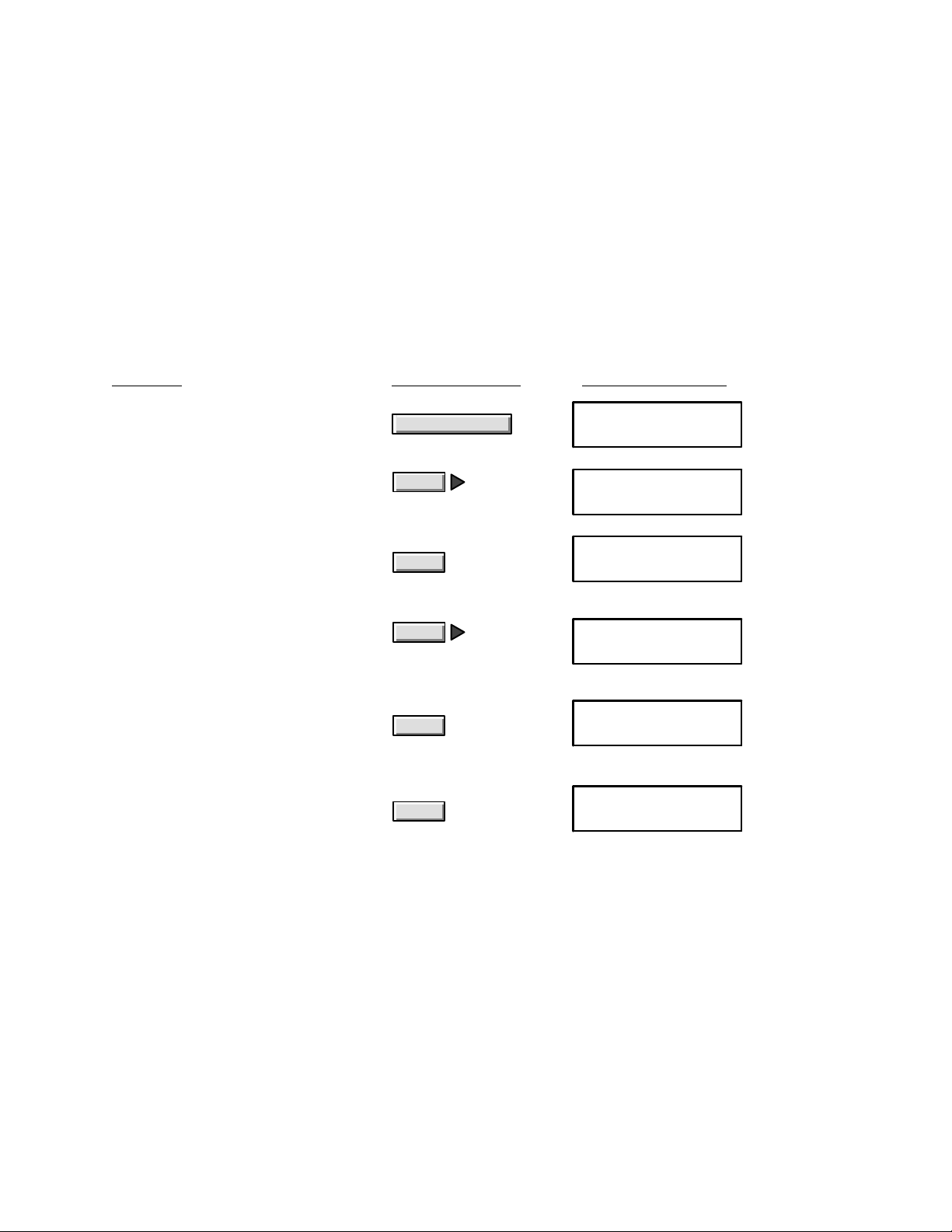
To change an HP OfficeJet parameter, perform the following steps:
1. Enter the parameter number.
2. Click on Retrieve to display the current value.
3. Type the new value in the Enter new value dialog box.
Note: If the user enters the same value in the “Enter new value” dialog box that appears
in the “Current value” Dialog box, the Retrieve and Apply buttons will be grayed
Installation and Configuration
2-11
Page 29
out. Either change the value in the “Enter new value” dialog box or enter a new
parameter number into the Parameter number dialog box.
4. Click on the Apply button to set the HP OfficeJet with the new parameter value.
If you want to change another parameter, repeat step 1.
Because there is no minimize button, use the alt and tab keys to hide or show the HP OfficeJet Service Application
window if another application has covered the Service Application window.
Exiting the Service Application
Whenever exiting the Service Application Program, allow 5 to 10 seconds for the hardware to
terminate the factory and service capability.
To exit or quit the program, click on the Exit button. After depressing the Exit button, be sure to wait 5 to 10 seconds
for the hardware to terminate the factory and service capability before taking any other action. During the transition
observe the OfficeJet front panel LCD display for the following events:
The phrase “Enter header number” appears on the top line of the HP OfficeJet LCD display.
A string of characters appear on the bottom line of the HP OfficeJet LCD display.
The HP OfficeJet LCD display blanks out briefly and returns to the normal “ready” state
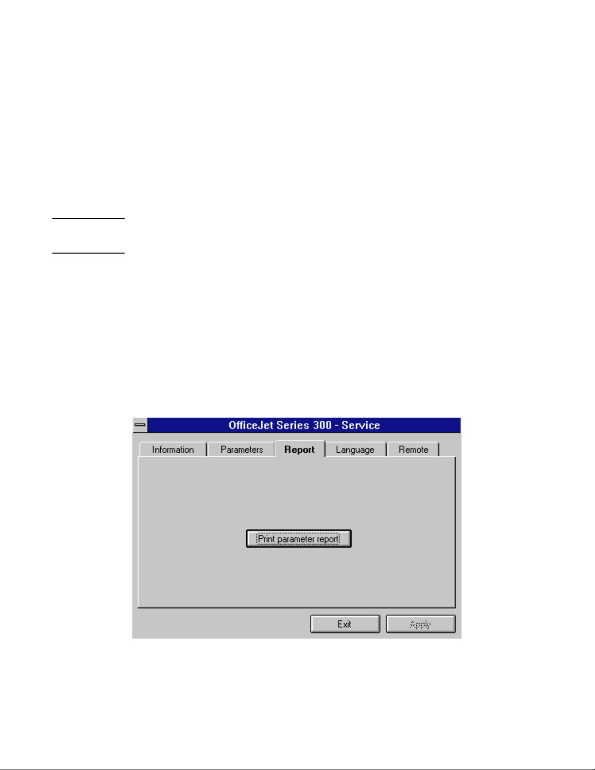
Printing a Parameter Report
Clicking on the “Report tab in the service application main menu causes the window to appear as follows:
To print a parameter report, click on the Print parameter report button.
Note: There is a 5 second delay before printing begins.
Installation and Configuration
2-12
Page 30
Exiting the Service Application
Whenever exiting the Service Application Program, allow 5 to 10 seconds for the hardware to
terminate the factory and service capability.
To exit or quit the program, click on the Exit button. After depressing the Exit button, be sure to wait 5 to 10 seconds
for the hardware to terminate the factory and service capability before taking any other action. During the transition
observe the OfficeJet front panel LCD display for the following events:
The phrase “Enter header number” appears on the top line of the HP OfficeJet LCD display.
A string of characters appears on the bottom line of the HP OfficeJet LCD display.
The HP OfficeJet LCD display blanks out briefly and returns to the normal “ready” state
Setting the Front Panel Language
Clicking on the “Language” tab in the service application main menu causes the window to appear as follows:
Select the language. Then Click Apply to set the front panel language.
Note: It takes 0 to 59 seconds (30 seconds on average) for the front panel menu of
the OfficeJet to change.
Exiting the Service Application
Whenever exiting the Service Application Program, allow 5 to 10 seconds for the hardware to
terminate the factory and service capability.
To exit or quit the program, click on the Exit button. After depressing the Exit button, be sure to wait 5 to 10 seconds
for the hardware to terminate the factory and service capability before taking any other action. During the transition
observe the OfficeJet front panel LCD display for the following events:
Installation and Configuration
2-13
Page 31

The phrase “Enter header number” appears on the top line of the HP OfficeJet LCD display.
A string of characters appears on the bottom line of the HP OfficeJet LCD display.
The HP OfficeJet LCD display blanks out briefly and returns to the normal “ready” state
Setting Remote Service
Clicking on the “Remote” tab in the service application main menu causes the window to appear as follows:
Click the square by the text,“Enable remote operation” to select On, then click “Apply”. Enabling remote operation
allows a service representative to diagnose HP OfficeJet from a remote location. When remote operations are
complete, click the square by the text, “Enable remote operation”a second time to select Off, then click “Apply”.
Exiting the Service Application
Whenever exiting the Service Application Program, allow 5 to 10 seconds for the hardware to
terminate the factory and service capability.
To exit or quit the program, click on the Exit button. After depressing the Exit button, be sure to wait 5 to 10 seconds
for the hardware to terminate the factory and service capability before taking any other action. During the transition
observe the OfficeJet front panel LCD display for the following events:
The phrase “Enter header number” appears on the top line of the HP OfficeJet LCD display.
A string of characters appears on the bottom line of the HP OfficeJet LCD display.
The HP OfficeJet LCD display blanks out briefly and returns to the normal “ready” state
Installation and Configuration
2-14
Page 32

Using Other PC Fax Programs With Models 330 and 350
The user can use most Windows-based PC fax software that supports standard CAS modems with the HP OfficeJet
Models 330 and 350. If the user is in doubt as to which applications can be used with the HP OfficeJet Series 300
Models 330 and 350, have him refer to the Software Compatibility Matrix that came with the machine. Please note
that the HP OfficeJet Series 300 Manager must be installed and running in order to use PC fax software with the HP
OfficeJet Series 300 Models 330 and 350.
If the installation fails for any reason, have the user refer to the application’s installation instructions or to the
“Troubleshooting” section in the HP OfficeJet Model 330 or 350 User’s Guide, Chapter 6.
Note: In order to run the HP OfficeJet Series 300 Manager and Eclipse FAX SE for PC
faxing and scanning, the user must be running Windows in 386 Enhanced Mode.
(To find out which mode the user is running, have him or her choose Help/About
Program Manager from the Windows Program Manager menu bar.) If the user has
an 80386 processor with at least 2 MB of RAM, the user’s PC should run Windows
in 386 Enhanced Mode by default. If the user has a 386 PC with at least 1 MB of
RAM but the user’s PC does not run Windows 386 mode by default, the user can
cause it to run in this mode by typing WIN/3 to run Windows, rather than WIN.
Installation and Configuration
2-15
Page 33

Installing Control Panel and One-Touch Overlays
Each HP OfficeJet Series 300 is shipped with a control panel overlay appropriate for the country of destination
installed. The overlay has the HP logo and HP Model 300, Model 330, or Model 350 name as well as the control panel
button names printed on it. If an overlay needs to be installed, remove the protective cover from the back of the overlay
and carefully position the overlay on the control panel. Then press the o verlay into place and remove the protective
cover from the top of the overlay. The illustration below shows the overlay in place with the protective cover being
removed.
One-Touch Speed Dial
SL50A
Removing the Protective Cover from the Top of the Control Panel Overlay
Each HP OfficeJet Series 300 is shipped with a One-Touch speed dial overlay and clear plastic protective cover for the
overlay installed. If a new overlay and protective cover need to be installed, position the overlay and cover over the
one-touch buttons as shown below. Press the overlay into place. Then place the protective cover over the overlay.
Insure that the tabs on the protective cover are properly seated.
Tab
Protective
Cover
Overlay
One-Touch Buttons
FX-75
Placing the OneĆTouch Speed Dial Overlay and Protective Cover Over the OneĆTouch Panel
Installation and Configuration
2-16
Page 34

Installing a Print Cartridge
With the control panel and top cover open, locate
1
the print cartridge cradle inside the HP OfficeJet
Series 300, near on the right side.
Print cartridge cradle
Place the print cartridge down into the cradle as
34
shown. Align the green arrow on the cartridge
top with the green dot on top of the cradle.
Open the print cartridge box and container, then
2
grasp the print cartridge by the green top and remove
the cartridge from the container. Gently remove both
pieces of tape – blue and white – covering the ink
nozzles and vent hole.
CAUTIONS: 1) If the user doesn’t remove the white
tape, the cartridge will prematurely fail.
2) Be careful not to touch the ink nozzles or the
copper contacts. Fingerprints may damage them.
SL16SL42A
Push the green arrow toward the green dot until
the cartridge snaps into place.
Remove both pieces of tape!
SL42
Close the top cover, then close the control panel.
5 Helpful Hint:
SL18A
SL43
Be sure to close the control panel firmly, until it
snaps into place.
Installation and Configuration
2-17
Page 35

Installing an Interface Cable for Printing
The user must purchase separately a shielded Centronics bi-directionsl parallel interface cable
to connect the HP OfficeJet Series 300 to his computer for printing. He or she can use the HP
C2950A (2 meter) or the HP C2951A (3 meter) Centronics parallel cable. See chapter 1of
this guide for ordering information.
Make sure the computer is turned off by pressing
“O” on the On/Off switch (located on the left side
of the machine’s base). Then remove the output
tray from the HP OfficeJet Series 300 and set it
aside.
Output Tray
SL6
Snap both clips into the notches on the connector
3
as shown.
Place the HP OfficeJet Series 300 on a stable
21
surface at a safe distance from the edge. Then tilt
and rotate it on its side so that the bottom of the
unit faces the user as shown below. Connect the
printer end* of the interface cable firmly to the
interface port on the HP OfficeJet.
* The printer end of the interface cable has
notches, and the computer end has screws.
SL54
Return the HP OfficeJet Model Series 300 to its
4
upright position, making sure it does not rest on
the interface cable. Insert the output tray.
Now connect the computer end of the interface
cable to the parallel (LPT 1) port on the
computer and tighten the screws on the
connector (not shown).
Installation and Configuration
2-18
SL51SL31
Page 36

Installing the Power Cord
Make sure the printer is turned off by pressing
“O” on the On/Off switch (located on the left side
of the machine’s base).
Look on the back of the HP OfficeJet Series 300
21
and locate the power socket. Then plug the power
cord connector firmly into the power socket.
WARNING: To avoid the possibility of electric
shock, plug the other end of the cord into a
grounded
SL53SL27
electrical outlet only.
Power
socket
Installing a Tray Wire
The document catch tray will hold the original documents after they have been scanned for faxing or copying.
Install the tray wire in the holes provided at the front of the output tray.
1
Ensure that the ends of the tray wire are securely in the holes.
Tray Wire
SL84
Installation and Configuration
2-19
Page 37

Installing an Access Door Assembly
The access door assembly contains the document feed tray and extender and adjustable paper size guides.
Originals of faxes to be sent or documents to be copied are placed on the feed tray for processing.
The tray extender can be raised to support legal size documents being faxed or copied.
The paper size guides are adjusted to fit the size of the original document being sent or copied.
To remove the old access door assembly, lift
1
open the control panel assembly and raise the
access door assembly to the fully open position.
Flex out the sides of the access door near
the lower corners and lift the access door
assembly straight up to remove it.
SL30A
Installing an Output Tray
Flex out the sides of the access door near the
2
lower corners and lower the new access door
assembly into place.
Close the access door and control panel
assemblies.
Be sure to close the control panel firmly, until it
snaps into place.
SL30B
The output tray collects faxes, print jobs, reports and copies after they are received and printed.
Remove the old output tray from the HP OfficeJet
1
Series 300.
SL6
Install the new output tray into the HP OfficeJet
2
Series 300.
SL51
Installation and Configuration
2-20
Page 38

Installing an Input Tray
The input tray is also known as the paper supply tray. This tray is where paper is loaded for the printing
of received faxes, print jobs, reports and copies. The tray holds 100 sheets of paper.
Remove the output tray from the HP OfficeJet
12
Series 300.
Remove the old tray by pulling the input tray forward to expose the flex tabs. Press down firmly
on the two flex tabs and pull the input tray out of
the unit. If the tray does not easily release, the
user may need to slide the tray in slightly, press
the flex tabs down again and pull the tray forward
and out of the unit..
Flex Tab
Flex Tab
SL6
SL2
When installing the new input tray, ensure
3
that the tray is properly aligned with its seat
and slide it all the way into the machine.
SL5
Pull the input tray out and check the posi-
4
tion of the paper size setting. Adjust if
necessary.
Slide the green paper guide until it snaps into
place at the appropriate paper size setting.
Note: Only letter-, legal-, and A4-size paper
can be loaded for fax reception and copying.
Be sure to set the paper size in the menu.
Paper Guide
SL3A
Installation and Configuration
2-21
Page 39

Loading Paper in the Input (Paper) Tray
Pull the input tray out until it is fully extended.
12
Check the position of the paper size setting
and adjust if necessary.
Slide the green paper guide until it snaps into
place at the appropriate paper size setting.
Note: Only letter-, legal-, and A4-size paper
can be loaded for fax reception and copying.
Be sure to set the paper size in the menu.
Remove the tray bridge by lifting it up and
off of the handle grip..
Paper Guide
SL2
Tray Bridge
SL3
Up to 100 sheets (about 1 cm. or 1/2-inch thick
34
Helpful Hints:
stack) can be loaded into the tray.
Load the paper (print side down), aligning the
right edge of the paper to the right side of the
tray. The paper stack should fit underneath the
Do not force the input tray all the way in when
closing it. The paper must not buckle or a paper
jam could occur.
grip on the input tray handle.
This table lists the allowable paper sizes.
Install the tray bridge by pressing it down
onto the handle grip.
Description
Letter
1
A4
Legal
Executive
Size
8.5 x 11 inches (216 x 279 mm)
8.27 x 11.7 inches (210 x 297 mm)
8.5 x 14 inches (216 x 356 mm)
2
7.25 x 10.5 inches (184 x 267 mm)
The tray bridge lifts printed faxes and pages
above the paper tray handle to prevent them
from becoming jammed inside the machine.
(The tray bridge must be used when receiving
faxes to legal-size paper or when printing on
glossy paper or HP Premium Transparency
Film.)
Input Tray Handle Grip
1
SL28
A4 is the standard size for letters in European countries.
2
The user cannot make copies or receive faxes on this paper
size.
Installation and Configuration
2-22
Page 40

Loading Envelopes in the Input (Paper) Tray
Pull the input tray out until it is fully extended.
12
The user can remove the output tray to facilitate
envelope loading as shown in this procedure. Be
Load up to 20 envelopes flap up, with the
top edge aligned to the right side of the
HP OfficeJet Series 300, as shown.
sure to install the output tray before printing.
SL7
SL8
Slide the green paper guide until it snaps into
34
place at the appropriate envelope size setting.
The envelope guide will pop up to keep the
Install the output tray. If necessary refer to
“Installing an Output Tray” earlier in this
chapter.
envelopes vertically aligned. Install the output
tray if not already installed.
Helpful Hints:
Do not force the input tray all the way in when
closing it. The envelopes must not buckle or a
paper jam could occur.
An “out of fax paper” error will display on the
front panel card of the HP OfficeJet Manager, if
it is open. Although the device is unable to detect the presence of envelopes even when properly loaded, it will print them.
The following table lists the two allowable
envelope sizes. Note that copies cannot be
made and faxes cannot be received on any
Paper Guide
SL9
U.S. No. 10
envelope
European DL
envelope
envelopes. Be sure to set the paper size in the
menu to envelopes before printing.
Description Size
U.S. No. 10
envelopes 9.5 x4.12 inches (241x105 mm)
European DL
envelopes 8.66x4.33 inches (220x110mm)
Installation and Configuration
2-23
Page 41
Setting the Paper Size in the Front Panel Menu
The paper size
in an HP OfficeJet Series 300 is setup during installation of the software but can be changed using the
HP OfficeJet Series 300 Manager software by selecting the Loaded Paper Size in the HP OfficeJet Series 300 Setup
dialog box as described in the HP OfficeJet Series 300 User’s Guide for the user’s model.
The paper size can also be set using the front panel menu as described below.
Set the paper size in the menu to match the paper size loaded in the input tray. Setting the paper size allows the
HP OfficeJet Series 300 to scale incoming faxes to fit the paper size loaded. The factory setting is Letter (8 1/2
x 11 inches). If Letter size paper is loaded, no change is required unless the menu setting was previously
changed and not reset to Letter size. If Legal or Envelope sizes are loaded, set the menu to the appropriate size.
Using
Do this:
1. Press the Menu button to display
the menu.
2. Press Right Arrow multiple
times to move to “Paper Size.”
3. Press Enter/Save to select “Paper
Size.” The selected paper size is
marked with an asterisk (*).
these buttons: For this display:
Menu
Enter/Save
MENU
Time/Date, Header
MENU
Paper Size
PAPER SIZE
Letter (8.5 x 11 in) *
4. Press Right Arrow multiple times
to move to the desired setting.
(The example is “Legal.”)
5. Press Enter/Save to select the
displayed setting. An asterisk (*)
denotes the new selection.
6. Press Enter/Save to return to the
Ready display.
Enter/Save
Enter/Save
PAPER SIZE
Legal (8.5x14 in)
PAPER SIZE
Legal (8.5x14 in) *
Ready Auto
Oct-10-95 10:47 AM
Installation and Configuration
2-24
Page 42

Setting Up for Printing
Using an HP OfficeJet Series 300 machine with the HP OfficeJet Series 300 Manager to control printing is briefly
described earlier in this section. Detailed and custom setup information is provided in the HP OfficeJet Series 300
User’s Guide for the user’s model.
In order to use the HP OfficeJet Series 300 printer function with a PC, the interface cable and a printer driver must be
installed to make the computer and computer software work with the HP OfficeJet. Printer drivers are software files
that control the printer and allow the computer software applications to access the printer’s features.
The HP OfficeJet Series 300 will work with Microsoft
Windows drivers are supplied with the HP OfficeJet Series 300. The user’s DOS application may have the appropriate
driver, if not, a separate DOS driver disk can be ordered from HP Driver Distribution Division. See the section,
“Ordering Information” in chapter 1. Install the drivers according to the instructions supplied with the drivers. Since
the HP OfficeJet Series 300 is compatible with HP DeskJet 520 and 510 printers, applications drivers for these
printers can be used with the HP OfficeJet Series 300.
Note: If using both Windows and DOS applications, be sure to exit Windows before
running the DOS applications. Do not run DOS applications from the MS-DOS
prompt from within Windows.
Each DOS software application requires a specific printer driver. Access to some printer features such as font selection
depends on the application and driver installed.
Determine if the user’s software application provides a printer driver that he or she can use.
Check the printer selection or printer setup menu in the user’s software application for a list of printer models. The list
below identifies recommended printer driver selections the user can use with the HP OfficeJet Series 300 and the type
of support that each offers:
Windows 3.1, Windows 95, and DOS software applications.
Use this printer driver selection:
For this type of printer support:
HP DeskJet 520 printer All printer features
HP DeskJet 510 printer All printer features
HP DeskJet 550C printer All printer features (except color)
HP DeskJet Portable printer All printer features except
envelope printing
HP DeskJet 500 printer All printer features except for some
fonts and envelope printing
Note: Unlike the HP DeskJet 520 printer, the HP OfficeJet Series 300 cannot be used with
external font cartridges nor accept character fonts downloaded from the PC.
Have the user select the printer driver using the instructions provided in the software application manual.
If the HP DeskJet 520 printer is not listed in the application, use one of the alternate printer drivers listed and have the
user contact his software company to determine if an HP DeskJet 520 printer driver is available. The user could also
try the HP DeskJet, HP DeskJet+ or other HP printer driver.
Note: The user may need to add or change the MODE statement in the user’s
AUTOEXEC.BAT file. The MODE statement tells the user’s computer where to
send printing information. This statement is not always required. If the HP
OfficeJet Series 300 will not print, have the user check the AUTOEXEC.BAT file to
make sure the MODE statement for a Centronics bidirectional parallel connection
to the LPT 1 port is: MODE LPT 1:,,P. If the user is not familiar with the
AUTOEXEC.BAT file, have the user refer to the DOS manual for information.
If the HP OfficeJet Series 300 will not print, reconnect the interface cable and try again before referring to the
troubleshooting chapter in this manual.
Installation and Configuration
2-25
Page 43

Setting Up for Faxing (U.S. and Australian Installations)
Using an HP OfficeJet Series 300 with the HP OfficeJet Series 300 Manager and Eclipse FAX SE to control faxing is
briefly described earlier in this section. Detailed information is provided in the HP OfficeJet Series 300 User’s Guide
for the user’s model.
be changed using the HP OfficeJet Series 300 Manager software as described in the HP OfficeJet Series 300 User’s
Guide for the user’s model.The reception mode can also be changed from the front panel as described later in this
chapter.
The following four types of installations are the ones recommended for use with the HP OfficeJet Series 300 to
achieve the best call-handling results. While other situations are possible, it is recommended that one of these be used.
Determine which installation most closely meets the user’s needs and follow the instructions given.
Receive fax calls only – no voice calls, on a dedicated fax line
Receive fax and voice calls at the same phone number – without an answering machine
Receive fax and voice calls at the same phone number – with an answering machine
Receive fax and voice calls on the same line with distinctive ring
After selecting the best installation to meet the user needs, the correct reception mode and certain station specific
information will need to be set up. The procedures to accomplish this are in the following topics:
Setting up for Distinctive Ring
Setting the Reception Mode for incoming calls
On an HP OfficeJet Series 300, reception mode is set during installation of the software, but can
Setting the number of rings to answer
Selecting Tone or Pulse dialing
Entering the Date and Time
Entering the header information (company name and fax number)
Note: The HP OfficeJet Series 300 is not supported with roll-over phone systems (such as
the automatic answering systems often used in large companies), voicemail, call
waiting, and some other advanced features provided by the user’s phone company.
If the user has call waiting or other features that can be temporarily turned off by
pressing a series of buttons on the user’s phone, we recommend that having the user
turn them off while sending and receiving faxes with the HP OfficeJet Series 300.
Check with the user’s phone company if the user needs help.
Receive fax calls only – no voice calls, on a dedicated fax line
This installation is recommended when using a separate telephone line and number dedicated to receiving faxes only
(no voice calls). Installation consists of connecting the HP OfficeJet Series 300 to the telephone wall jack with the
telephone cord provided with the machine and setting the Receive Mode to Auto. Auto receive mode is the factory
default set at shipment. If the setting was changed and the user wants to use Auto mode reception, have the user set the
mode to Auto. Instructions for setting the Reception Modes are provided later in this chapter.
Note: In Auto receiv e mode, the HP OfficeJet Series 300 will pick up the line after
detecting the number of rings specified in the Rings to Answer setting and then
send a fax tone signal to the calling fax machine to start communication. The fax is
then sent and the HP OfficeJet Series 300 will start to receive it. The Rings to
Answer setting is user defined through the front panel menu. The user can choose
from 2 to 5 rings. The factory default is 2 rings.
Installation and Configuration
2-26
Page 44

Receive fax and voice calls at the same phone number – without an answering machine
This installation is recommended when using one telephone number for both fax and voice calls and not using a
telephone answering machine. Installation consists of connecting the HP OfficeJet Series 300 to the telephone wall
jack, connecting a telephone directly to the HP OfficeJet Series 300 and setting the Receive Mode to Manual.
Instructions for setting the Receive Modes are provided later in this chapter.
HP OfficeJet
Series 300
Optional:
The user can
connect a telephone to
the “TEL” socket of the
HP OfficeJet Series 300
for outgoing voice calls
if desired.
Cord to socket labelled “LINE”
SLX19
Note: In Manual receive mode the HP OfficeJet Series 300 will never pick up the line to
answer a call. All calls must be answered manually. Voice calls are treated as
normal voice calls by answering the phone. To receive a fax, the user must first
answer the phone, listen for the fax tone and then press the Start/Copy button on
the front panel. For fax calls, the user must use the telephone that is directly
connected to the TEL jack on the back of the HP OfficeJet Series 300. After
answering the phone and the caller notifies the user that a fax is about to be sent to
him, or the user hears a fax tone, presses the Start/Copy button and then hangs up
the telephone. The fax is then sent and the HP OfficeJet Series 300 will start to
receive it.
Telephone Wall Jack
SLX20
If the user has a shared fax/voice line and wants to be able to receive faxes
automatically, the user cannot use Manual receive mode. To receive faxes
automatically, the user needs to either connect an answering machine to the HP
OfficeJet Series 300 and use Auto receive mode or, if the user’s phone company has
a distinctive ringing service available, he could connect his HP OfficeJet Series 300
to receive fax and voice calls on the same line with distinctive ring in Auto receive
mode. Information on using an answering machine or distinctive ring are provided
later in this chapter.
HP OfficeJet
Series 300
Telephone Wall Jack
Cord to socket labelled “TEL”
Telephone
Cord to socket labelled “LINE”
Installation and Configuration
2-27
Page 45

Receive fax and voice calls at the same phone number – with an answering machine
This installation is recommended when using one telephone number for both fax and voice calls and using a telephone
answering machine. Installation consists of connecting the HP OfficeJet Series 300 to the telephone wall jack,
connecting a telephone answering machine directly to the HP OfficeJet Series 300 and setting the Receive Mode to
Auto. Instructions for setting the Receive Mode are provided later in this chapter, but, with an answering machine
connected, ensure that the rings to answer setting of the HP OfficeJet is greater than the rings to answer setting of the
answering machine. If the answering machine has answered, the HP OfficeJet will eavesdrop and take the call if
another fax machine is calling. Two scenarios are possible when using an answering machine – one where the
telephone handset is an attached part of the answering machine and one where the telephone is a separate item that
must be connected to the answering machine that is directly connected to the HP OfficeJet Series 300. Both scenarios
are depicted in the following diagram.
HP OfficeJet
Series 300
Telephone Wall Jack
Answering Machine
To TAM socket labelled “TEL”
Note: TAM stands for Telephone Answering Machine
SLX22
Note: In Auto receive mode, if an answering machine has answered, the HP OfficeJet
Series 300 will eavesdrop and, if a calling fax is detected, will pick up the line after
detecting the number of rings specified in the Rings to Answer setting. It will then
send a fax tone signal to the calling fax machine to start communication. If no
answering machine has answered, the OfficeJet will wait to detect the number of
rings specified in the Rings to Answer setting. It will then send a fax tone signal to
the calling fax machine to start communication. The fax is then sent and the HP
OfficeJet Series 300 will start to receive it. The Rings to Answer setting is user
defined through the front panel menu. The user can choose from 1 to 5 rings. The
factory default is 2 rings, but it should be set to a number greater than the number
of rings to answer setting of the answering machine, if one is connected.
Cord to socket labelled “LINE”
Cord to socket labelled “TEL”
Telephone
To TAM socket labelled “Line” or “Wall”
Installation and Configuration
2-28
Page 46

Receive fax and voice calls on the same line with distinctive ring
This installation is recommended when using one telephone number for both fax and voice calls and using a
distinctive ringing service through the local telephone company. The telephone company’s distinctive ring service
allows the use of 2 or 3 phone numbers on the same phone line. The HP OfficeJet Series 300, however, will only accept
up to 2 numbers on a single line. Each of the phone numbers will have a distinctive ringing pattern: The first phone
number will have a single ring (ring) and the second will have a double ring (ring-ring) pattern. When activated, the
HP OfficeJet Series 300 distinctive ring feature can use the ring patterns to distinguish between fax and voice calls
received on the same line. The feature will need to be set to On in the HP OfficeJet Series 300 if distinctive ring is to be
used. If not used, the feature must be deactivated. Factory default for the feature is Off.
Note: The distinctive ring feature is not available in all local telephone system networks.
Currently, only certain U.S. regions and some Asian countries offer the service. The
local telephone company should be contacted for availability of the service.
This application can be used either with or without an answering machine attached to the HP OfficeJet Series 300.
Installation and setup for use of distinctive ring is as follows:
1. Connect the HP OfficeJet Series 300 to the telephone wall jack.
2. If an answering machine is to be used, connected it to the HP OfficeJet Series 300, or to a separate wall jack.
3. Set the HP OfficeJet Series 300 Receive Mode to Auto, or fax calls will not be received.
4. Also, if connecting an answering machine for voice calls on this line, make sure the Rings to Answer setting on the
HP OfficeJet Series 300 is set to a number greater than the setting on the answering machine that controls the number
of rings before answering. For example, if the answering machine is set to 2 rings to answer, set the HP OfficeJet
Series 300 to 3 or more rings to answer. CAUTION: If the user doen’t do this, he or she may not receive fax calls
properly. Instructions on setting the Receive Mode and HP OfficeJet Series 300 Rings to Answer number are given
later in this chapter.
HP OfficeJet Series 300
Optional:
The user can
connect a telephone or
answering machine to the
“TEL” socket of the HP
OfficeJet Series 300.
Cord to socket labelled “LINE”
SLX19
Note: If using the telephone company’s distinctive ring service, have the single-ring
assigned to the phone number at which voice calls are to be received and the
multiple-rings assigned to the phone number(s) at which the fax calls are to be
received. When the HP OfficeJet Series 300’s Distinctive Ring feature is set to On,
it will only answer the phone and receive fax es when it detects any multiple ring
pattern.
Telephone Wall Jack
The factory default setting for the HP OfficeJet Series 300 distinctive ring feature is Off. The feature should not be set
to On unless the user has already subscribed to the telephone company’s distinctive ring service. If set to On before
service is established, the HP OfficeJet Series 300 will not receive faxes automatically.
Installation and Configuration
2-29
Page 47

Setting Up for Distinctive Ring
Distinctive Ring in an HP OfficeJet Series 300 is set Off, but can be set On using the HP OfficeJet Series 300 Manager
software by selecting the Distinctive Ring in the Receive Fax Setup dialog box as described in the HP OfficeJet Series
300 User’s Guide for the user’s model. To set the HP OfficeJet Series 300 distinctive ring feature to On at the front
panel, use the following instructions:
Do this: Using these buttons: For this display:
a. Press the Menu button to display the menu.
b. Press Right Arrow multiple times to move to
“Fax Settings.”
c. Press Enter/Save to select “Fax Settings.”
d. Press Right Arrow multiple times to move to
“Phone Setup.”
e. Press Enter/Save to select “Phone Setup.”
f. Press Right Arrow multiple times to move to
“Distinctive Ring.”
g. Press Enter/Save to select “Distinctive Ring.”
Note that an asterisk (*) denotes the current
selection.
Menu
Enter/Save
Enter/Save
Enter/Save
MENU
Time/Date, Header
MENU
Fax Settings
FAX SETTINGS
Speed Dial Setup
FAX SETTINGS
Phone Setup
PHONE SETUP
Rings to Answer
PHONE SETUP
Distinctive Ring
DISTINCTIVE RING
Off *
h. Press Right Arrow to move to the desired
setting..
i. Press Enter/Save to select the displayed setting.
An asterisk (*) denotes the user’s new selection.
j. Press Enter/Save again to return to the
Ready display.
Installation and Configuration
2-30
Enter/Save
Enter/Save
DISTINCTIVE RING
On
DISTINCTIVE RING
On *
Ready Auto
Nov-10-95 12:45 PM
Page 48

Setting the Reception Mode for Incoming Calls
The Reception Mode affects how the HP OfficeJet Series 300 answers incoming fax and voice calls. Use the following
instructions to change the Reception Mode setting. Reception mode in an HP OfficeJet Series 300 is set during
installation of the software, but can be changed using the HP OfficeJet Series 300 Manager software by selecting the
Receive Mode in the Receive Fax Setup dialog box as described in the HP OfficeJet Series 300 User’s Guide for the
user’s model. Below is a diagram detailing the steps to change the reception mode using the front panel followed by a
table of the types of setups and the mode to use with each setup.
Do this: Using these buttons: For this display:
1. Make sure the HP OfficeJet Series 300
is turned ON.
2. Press the Receive Mode button to display
the current Receive Mode setting, which is
marked with an asterisk (*). (The example
shown is Auto, the factory setting.)
3. Press Receive Mode multiple times to get to
the appropriate setting (see the following table)
(“Manual,” shown at right, is only an example.)
4. Press Enter/Save to select the displayed setting.
Note that an asterisk (*) denotes the new selection.
5. Press Enter/Save again to return to the Ready
display. Note that the Receive Mode selected is
displayed on the top line next to “Ready.”
If the user has Set the
this type of setup:
Dedicated fax line
Receive Mode to: And read this note:
Auto
(receives only fax calls)
Shared fax/voice line,
Manual
no answering machine,
telephone connected
to HP OfficeJet Series
300
Shared fax/voice line,
Auto Select the rings to answer for the HP OfficeJet
with answering machine
Ready Auto
Nov-10-95 12:30 PM
Receive Mode
Receive Mode
Enter/Save
Enter/Save
RECEIVE MODE
Auto *
RECEIVE MODE
Manual
RECEIVE MODE
Manual *
Ready Manual
Nov-10-95 12:32 PM
When Auto is selected with a dedicated fax line, the
HP OfficeJet Series 300 answers all incoming calls
after the number of rings specified in the Rings to
Answer setting and sends out fax reception tones to
receive a fax.
When Manual is selected, the HP OfficeJet Series
300 never answers incoming calls. To receive a fax,
pick up the handset of the phone connected to the
HP OfficeJet Series 300, press the Start/Copy button, then hang up the phone.
Series 300 to a number of rings greater than that
selected for the answering machine. The HP
OfficeJet answers all incoming calls after the
number of rings selected if the answering machine
hasn’t answered. If the answering machine answers,
the HP OfficeJet will eavesdrop and take the call if
another fax machine is calling.
Shared fax/voice line,
with Distinctive Ring
feature (with or without
an answering machine)
Auto
When Auto is selected and user has subscribed to a
distinctive ring feature through the user’s phone company, the HP OfficeJet Series 300 will only answer
incoming calls with any multiple-ringing pattern.
Installation and Configuration
2-31
Page 49

Setting the Number of Rings to Answer
The number of rings setting is ONLY used when the HP OfficeJet Series 300 is in the Auto Receive Mode. This setting
is determines the number of rings sensed before the HP OfficeJet Series 300 answers a call. Although the range of
rings may vary for different countries, in the U.S.A., up to 5 rings can be set. The factory default setting is 2 rings. If an
answering machine is connected to the
OfficeJet is greater than the rings to answer setting of the answering machine. If the answering machine has answered,
the OfficeJet will eavesdrop and take the call if another fax machine is calling. The number of rings
OfficeJet Series 300 is set during installation of the software, but can be changed using the HP OfficeJet Series 300
Manager software by setting the Rings to Answer in the Receive Fax Setup dialog box as described in the HP OfficeJet
Series 300 User’s Guide for the user’s model. To change the rings to answer using the front panel use the following
instructions:
HP OfficeJet Series 300, ensure that the rings to answer setting of the HP
to answer in an HP
Do this:
1. Press the Menu button to display the Menu.
2. Press Right Arrow multiple times to move
to “Fax Settings.”
3. Press Enter/Save to select “Fax Settings.”
4. Press Right Arrow multiple times to move
to “Phone Setup.”
5. Press Enter/Save to select “Phone Setup.”
(“Rings to Answer” is displayed.)
6. Press Enter/Save to select “Rings to
Answer.” The allowable range (in brackets)
and the factory setting (far right) are displayed.
Using these buttons: For this display:
Menu
Enter/Save
Enter/Save
Enter/Save
MENU
Time/Date, Header
MENU
Fax Settings
FAX SETTINGS
Speed Dial Setup
FAX SETTINGS
Phone Setup
PHONE SETUP
Rings to Answer
Rings to Answer
[1-5] 2
7. Enter a number up to 5, inclusive.
(The example shows that 5 has been entered.)
8. Press Enter/Save to save the new value and
return to the Ready display.
Installation and Configuration
2-32
5
Enter/Save
Rings to Answer
[1-5] 5
Ready Auto
Nov-10-95 12:36 PM
Page 50

Selecting Tone or Pulse Dialing
The HP OfficeJet Series 300 is factory set for touchtone (Tone) dialing telephone systems. If used with a rotary (Pulse)
dialing telephone system, the HP OfficeJet Series 300 will need to be set for Pulse dialing. This procedure can be used
to set for either dialing system as required. The dialing mode in an HP OfficeJet Series 300 is set during installation of
the software, but can be changed using the front panel or using the HP OfficeJet Series 300 Manager software and
selecting Tone or Pulse in the Dialing Mode menu of the Send Fax Setup dialog box as described in the HP OfficeJet
Series 330 or 350 User’s Guide. To select the dialing mode from the front panel use the following instructions:
Do this: Using these buttons: For this display:
1. Press the Menu button to display the menu.
2. Press Right Arrow multiple times to move
to “Fax Settings.”
3. Press Enter/Save to select “Fax Settings.”
4. Press Right Arrow multiple times to move
to “Phone Setup.”
5. Press Enter/Save to select “Phone Setup.”
6. Press Right Arrow multiple times to move
to “Dialing Mode.”
7. Press Enter/Save to select “Dialing Mode.”
The factory setting, Tone, is displayed.
Menu
Enter/Save
Enter/Save
Enter/Save
MENU
Time/Date, Header
MENU
Fax Settings
FAX SETTINGS
Speed Dial Setup
FAX SETTINGS
Phone Setup
PHONE SETUP
Rings to Answer
PHONE SETUP
Dialing Mode
DIALING MODE
Tone *
8. Press Right Arrow to move to “Pulse.”
9. Press Enter/Save to select “Pulse.” An
asterisk (*) denotes the user’s new selec-
tion.
10.Press Enter/Save again to return to the
Ready display.
Enter/Save
Enter/Save
DIALING MODE
Pulse
DIALING MODE
Pulse *
Ready Auto
Nov-10-94 12:41 PM
Installation and Configuration
2-33
Page 51

Entering the Date and Time
Date and Time entries are required on all outgoing faxes. The fax log report will also reflect the date and time of
transactions for reference. When entering the information, the current date and time should be entered for accurate
reports and tracking of transactions. The date and time information in an HP OfficeJet Series 300 is set during
installation of the software, but can be changed using the front panel or using the HP OfficeJet Series 300 Manager
software , selecting the Send Fax Setup dialog box and entering the information as described in the HP OfficeJet
Series 330 or 350 User’s Guide.
Note: The Telephone Protection Act of 1991 requires that all faxes transmitted in the
U.S.A. display the date and time they are sent in a header, footer or cover page.
Most applications contain the information in the document header.
The date and time can be entered from the front panel using the following procedure:
Do this: Using these buttons: For this display:
1. Press the Menu button to display the menu.
(“Time/Date, Header” is displayed.)
2. Press Enter/Save to select “Time/Date,
Header.” (“Time/Date” is displayed.)
3. Press Enter/Save to select “Time/Date.”
4. Press “1” if entering the time in AM/PM
format, or press “2” to enter the
time in 24-hour format. (The example shows
the AM/PM format.)
5. Enter the current time in the format
selected. (Example shows AM/PM format.)
Press the Backspace button to correct any
mistakes.
6. Enter the current date in month-day-year
format.
7. Press Enter/Save to save the date
entered.
Menu
Enter/Save
Enter/Save
12
09
0
Enter/Save
or
through
through
9
MENU
Time/Date, Header
TIME/DATE, HEADER
Time/Date
Enter time format
1=AM/PM 2=24-hour
Enter time
12:46 PM
Enter 1=AM 2=PM
08:05 PM
Enter date
11-10-95
Ready Auto
Nov-10-95 08:05 AM
Installation and Configuration
2-34
Page 52

Entering the Header Information (company name and fax number)
Sender Identification and fax number entries are required on all outgoing faxes. This information will appear in the
header of transactions for reference. The header information in an HP OfficeJet Series 300 is set during installation of
the software, but can be changed using the HP OfficeJet Series 300 Manager software by selecting the Send Fax Setup
dialog box and entering the information as described in the HP OfficeJet Series 300 User’s Guide.
The header information can also be changed using the front panel menu. The procedures to change the header
information using the front panel is shown on the next page of this guide.
Note: The Telephone Protection Act of 1991 requires that all faxes transmitted in the
U.S.A. display the sender’s identifying name and fax number in a header, footer or
cover page. Most applications contain the information in the document header.
Use the procedure on the next page to enter header information using the front panel.
Installation and Configuration
2-35
Page 53

Do this: Using these buttons: For this display:
1. Press the Menu button to display the menu.
“Time/Date, Header” is displayed.
2. Press Enter/Save to select “Time/Date,
Header.”
3. Press Right Arrow to move to “Fax Header.”
4. Press Enter/Save to select “Fax Header.”
5. Type the desired name to be displayed in the
header of the user’s outgoing faxes, using
Menu
Enter/Save
Enter/Save
ABC
29
WXYZ
through
MENU
Time/Date, Header
TIME/DATE, HEADER
Time/Date
TIME/DATE, HEADER
Fax Header
Enter header name
Enter header name
ACME Co.
theseguidelines:
•Enter up to 25 characters, including letters, symbols, and spaces.
• Use the number buttons 2 through 9 to enter the lowercase and uppercase letters shown above the buttons.
Note: When the cursor is at a given position, pressing a number button multiple times
will cause the characters associated with that button to appear in succession. For
example, pressing the number button, 2, will cause the letters, a, b, c, A, B, and C
to appear in succession.
• After entering a character, use Right Arrow to move the cursor to the right before entering the next
character.
• Use the Space button to enter a space.
• Use the Symbols button to enter punctuation and symbols, such as a period (.), an asterisk (*), or an at
sign (@).
To delete an unwanted character in the user’s header, move the cursor one space to the right of the character
and press the Backspace button.
6. Press Enter/Save to save the name typed.
Enter/Save
Enter header number
7. Enter the telephone number of the fax line
connected to the user’s HP OfficeJet Series
300 using these guidelines:
through
0
9
Enter header number
619 555–1234
• Up to 20 characters are allowed, including numbers, spaces, dashes (–), and the plus sign (+).
• Use the Space button to enter a space.
• Use the Redial/Pause button to enter a dash (–).
• Use the Symbols button to enter a plus sign (+) before the country code when dialing the user’s fax
number from another country. (For example, +1 619 555–1234.) The country code for the U.S. and Canada
is 1. For more information about international calls, contact the telephone company.
To delete an unwanted number or symbol, use the Backspace button.
8. Press Enter/Save to save the fax number
entered and return to the Ready display.
Enter/Save
Ready Auto
Nov-10-95 08:15 AM
Installation and Configuration
2-36
Page 54

Setting Up for Faxing (U.K. Installation)
The following types of installations are the ones recommended for use with the HP OfficeJet Series 300 to achieve the
best call-handling results. While other situations are possible, it is recommended that one of these be used. Determine
which installation most closely meets the user’s needs and follow the instructions given.
Receive fax calls only – no voice calls, on a dedicated fax line
Receive fax and voice calls at the same phone number – without an answering machine
Receive fax and voice calls at the same phone number – with an answering machine
After selecting the best installation to meet the user needs, the correct reception mode and certain station specific
information will need to be set up. The procedures to accomplish this are in the following topics which are presented
in the HP OfficeJet Series 300 User’s Guide for the user’s model:
Setting the Reception Mode for incoming calls
Setting the number of rings to answer
Selecting Tone or Pulse dialing
Entering the Date and Time
Entering the header information (company name and fax number)
The above operations can also be accomplished from the front panel as described earlier in this chapter.
Refer to the HP OfficeJet Series 300 User’s Guide for the user’s model about how to use the Mercury Telephone
Network System.
Using an HP OfficeJet Series 300 with the HP OfficeJet Series 300 Manager and Eclipse FAX SE to control faxing is
briefly described earlier in this section. Detailed information is provided in the HP OfficeJet Series 300 User’s Guide.
Reception mode in an HP OfficeJet Series 300 is set during installation of the software, but can be changed using the
HP OfficeJet Series 300 Manager software by selecting the Receive Mode in the Receive Fax Setup dialog box as
described in the HP OfficeJet Series 300 User’s Guide for the user’s model.
The reception mode can also be changed using the front panel as described earlier in this chapter.
Installation and Configuration
2-37
Page 55

Receive fax calls only – no voice calls, on a dedicated fax line
This installation is recommended when using a separate telephone line and number dedicated to receiving faxes only
(no voice calls). Installation consists of connecting the HP OfficeJet Series 300 to the telephone wall jack using the
telephone cord provided, and setting the Receive Mode to Auto. Refer to the HP OfficeJet Series 300 User’s Guide for
the user’s model or to the instructions on setting up the Reception Mode from the front panel given earlier in this
chapter.
HP OfficeJet
Series 300
Telephone Wall Jack
SLX1
Receive fax and voice calls at the same phone number – without an answering machine
This installation is recommended when using one telephone number for both fax and voice calls and not using a
telephone answering machine. Installation consists of connecting the HP OfficeJet Series 300 to the telephone wall
jack, connecting the telephone directly to the HP OfficeJet Series 300 wall jack connector as shown, and setting the
Receive Mode to Manual. Refer to the HP OfficeJet Series 300 User’s Guide for the user’s model or to the instructions
on setting up the Reception Mode from the front panel given earlier in this chapter.
HP OfficeJet
Series 300
Telephone
Telephone Wall Jack
SLX2
Installation and Configuration
2-38
Page 56

Receive fax and voice calls at the same phone number – with an answering machine
This installation is recommended when using one telephone number for both fax and voice calls and using a telephone
answering machine. Installation consists of connecting the HP OfficeJet Series 300 to the telephone wall jack,
connecting the telephone answering machine directly to the HP OfficeJet Series 300 wall jack connector as shown,
and setting the Receive Mode to Auto. Ensure that the rings to answer setting of the HP OfficeJet is greater than the
rings to answer setting of the answering machine. If the answering machine has answered, the HP OfficeJet will
eavesdrop and take the call if another fax machine is calling. Two scenarios are possible when using an answering
machine – one where the telephone handset is an attached part of the answering machine and one where the telephone
is a separate item that must be connected following the answering machine. Both scenarios are depicted in the
following diagram.
HP OfficeJet
Series 300
Answering Machine
Telephone Wall Jack
SLX3
HP OfficeJet
Series 300
Telephone
Telephone Wall Jack
SLX4
For use with separate telephone. Attach the telephone after the answering machine cord is connected.
Answering Machine
Installation and Configuration
2-39
Page 57

Setting Up for Faxing (Germany Installation)
The following types of installations are the ones recommended for use with the HP OfficeJet Series 300 to achieve the
best call-handling results. While other situations are possible, it is recommended that one of these be used. Determine
which installation most closely meets the user’s needs and follow the instructions given.
Receive fax calls only – no voice calls, on a dedicated fax line
Receive fax and voice calls at the same phone number – without an answering machine
Receive fax and voice calls at the same phone number – with an answering machine
After selecting the best installation to meet the user needs, the correct reception mode and certain station specific
information will need to be set up. The procedures to accomplish this are in the following topics which are presented
in the HP OfficeJet Series 300 User’s Guide for the user’s model:
Setting the Reception Mode for incoming calls
Setting the number of rings to answer
Selecting Tone or Pulse dialing
Entering the Date and Time
Entering the header information (company name and fax number)
The above operations can also be accomplished from the front panel as described earlier in this chapter.
Refer to the HP OfficeJet Series 300 User’s Guide for the user’s model to find out how to use in a PBX system.
Using an HP OfficeJet Series 300 with the HP OfficeJet Series 300 Manager and Eclipse FAX SE to control faxing is
briefly described earlier in this section. Detailed information is provided in the HP OfficeJet Series 300 User’s Guide.
Reception mode in an HP OfficeJet Series 300 is set during installation of the software, but can be changed using the
HP OfficeJet Series 300 Manager software by selecting the Receive Mode in the Receive Fax Setup dialog box as
described in the HP OfficeJet Series 300 User’s Guide for the user’s model.
the front panel as described earlier in this chapter.
Reception modes can also be changed from
The types of installation recommended can be depicted in the same diagrams as shown on the next two pages.
Installation consists of connecting the HP OfficeJet Series 300, telephone, and answering machine directly to the
telephone wall jack as shown. Set the Receive Mode as specified in the HP OfficeJet Series 300 User’s Guide for the
user’s model.
Installation and Configuration
2-40
Page 58

Receive fax calls only – no voice calls, on a dedicated fax line
This installation is recommended when using a separate telephone line and number dedicated to receiving faxes only
(no voice calls). Installation consists of connecting the HP OfficeJet Series 300 to the telephone wall jack using the
telephone cord provided, and setting the Receive Mode to Auto. Refer to the HP OfficeJet Series 300 User’s Guide for
the user’s model or to the instructions on setting up the Reception Mode from the front panel given earlier in this
chapter.
HP OfficeJet
Series 300
Telephone Wall Jack
SLX11
Connect the telephone to the left jack.
Receive fax and voice calls at the same phone number – without an answering machine
This installation is recommended when using one telephone number for both fax and voice calls and not using a
telephone answering machine. Installation consists of connecting the HP OfficeJet Series 300 to the telephone wall
jack, connecting the telephone directly to the HP OfficeJet Series 300 wall jack connector as shown, and setting the
Receive Mode to Manual. Refer to the HP OfficeJet Series 300 User’s Guide for the user’s model or to the instructions
on setting up the Reception Mode from the front panel given earlier in this chapter.
HP OfficeJet
Series 300
Telephone
SLX12
Telephone Wall Jack
Connect the telephone to the center jack.
Installation and Configuration
2-41
Page 59

Receive fax and voice calls at the same phone number – with an answering machine
This installation is recommended when using one telephone number for both fax and voice calls and using a telephone
answering machine. Installation consists of connecting the HP OfficeJet Series 300 to the telephone wall jack,
connecting the telephone answering machine directly to the HP OfficeJet Series 300 wall jack connector as shown,
and setting the Receive Mode to Auto. If an answering machine is connected to the
that the rings to answer setting of the HP OfficeJet is greater than the rings to answer setting of the answering machine.
If the answering machine has answered, the HP OfficeJet will eavesdrop and take the call if another fax machine is
calling. Two scenarios are possible when using an answering machine – one where the telephone handset is an
attached part of the answering machine and one where the telephone is a separate item that must be connected
following the answering machine. Both scenarios are depicted in the following diagram.
HP OfficeJet Series 300, ensure
HP OfficeJet
Series 300
SLX13
Telephone Wall Jack
HP OfficeJet
Series 300
Answering Machine
Connect the answering
machine to the right-hand jack.
Answering Machine
SLX14
Telephone Wall Jack
Installation and Configuration
2-42
Telephone
Connect the telephone to the center jack,
answering machine to the right-hand jack.
Page 60

Setting Up for Faxing (France Installation)
The following types of installations are the ones recommended for use with the HP OfficeJet Series 300 to achieve the
best call-handling results. While other situations are possible, it is recommended that one of these be used. Determine
which installation most closely meets the user’s needs and follow the instructions given.
Receive fax calls only – no voice calls, on a dedicated fax line
Receive fax and voice calls at the same phone number – without an answering machine
Receive fax and voice calls at the same phone number – with an answering machine
After selecting the best installation to meet the user needs, the correct reception mode and certain station specific
information will need to be set up. The procedures to accomplish this are in the following topics which are presented
in the HP OfficeJet Series 300 User’s Guide for the user’s model:
Setting the Reception Mode for incoming calls
Setting the number of rings to answer
Selecting Tone or Pulse dialing
Entering the Date and Time
Entering the header information (company name and fax number)
The above operations can also be accomplished from the front panel as described earlier in this chapter.
Using an HP OfficeJet Series 300 with the HP OfficeJet Series 300 Manager and Eclipse FAX SE to control faxing is
briefly described earlier in this section. Detailed information is provided in the HP OfficeJet Series 300 User’s Guide
for the user’s model.
Reception mode in an HP OfficeJet Series 300 is set during installation of the software, but can
be changed using the HP OfficeJet Series 300 Manager software by selecting the Receive Mode in the Receive Fax
Setup dialog box as described in the HP OfficeJet Series 300 User’s Guide for the user’s model.
also be changed from the front panel as described earlier in this chapter.
Reception modes can
Installation and Configuration
2-43
Page 61

Receive fax calls only – no voice calls, on a dedicated fax line
This installation is recommended when using a separate telephone line and number dedicated to receiving faxes only
(no voice calls). Installation consists of connecting the HP OfficeJet Series 300 to the telephone wall jack using the
telephone cord provided, and setting the Receive Mode to Auto. Refer to the HP OfficeJet Series 300 User’s Guide for
the user’s model or to the instructions on setting up the Reception Mode from the front panel given earlier in this
chapter.
HP OfficeJet
Series 300
Telephone Wall Jack
SLX1
Receive fax and voice calls at the same phone number – without an answering machine
This installation is recommended when using one telephone number for both fax and voice calls and not using a
telephone answering machine. Installation consists of connecting the HP OfficeJet Series 300 to the telephone wall
jack, connecting the telephone directly to the HP OfficeJet Series 300 wall jack connector as shown, and setting the
Receive Mode to Manual. Refer to the HP OfficeJet Series 300 User’s Guide for the user’s model or to the instructions
on setting up the Reception Mode from the front panel given earlier in this chapter.
HP OfficeJet
Series 300
Telephone
Telephone Wall Jack
SLX6
Installation and Configuration
2-44
Page 62

Receive fax and voice calls at the same phone number – with an answering machine
This installation is recommended when using one telephone number for both fax and voice calls and using a telephone
answering machine. Installation consists of connecting the HP OfficeJet Series 300 to the telephone wall jack,
connecting the telephone answering machine directly to the HP OfficeJet Series 300 wall jack connector as shown,
and setting the Receive Mode to Auto. If an answering machine is connected to the
that the rings to answer setting of the HP OfficeJet is greater than the rings to answer setting of the answering machine.
If the answering machine has answered, the HP OfficeJet will eavesdrop and take the call if another fax machine is
calling. Two scenarios are possible when using an answering machine – one where the telephone handset is an
attached part of the answering machine and one where the telephone is a separate item that must be connected
following the answering machine. Both scenarios are depicted in the following diagram.
HP OfficeJet
Series 300
HP OfficeJet Series 300, ensure
Telephone Wall Jack
SLX7
HP OfficeJet
Series 300
Telephone Wall Jack
SLX9
Answering Machine with
attached handset
Answering Machine
Telephone
For use with separate telephone if the phone handset
is not part of the answering machine, attach after the
answering machine cord is connected
Installation and Configuration
2-45
Page 63

Setting Up for Faxing (Netherlands Installation)
The following types of installations are the ones recommended for use with the HP OfficeJet Series 300 to achieve the
best call-handling results. While other situations are possible, it is recommended that one of these be used. Determine
which installation most closely meets the user’s needs and follow the instructions given.
Receive fax calls only – no voice calls, on a dedicated fax line
Receive fax and voice calls at the same phone number – without an answering machine
Receive fax and voice calls at the same phone number – with an answering machine
After selecting the best installation to meet the user needs, the correct reception mode and certain station specific
information will need to be set up. The procedures to accomplish this are in the following topics which are presented
in the HP OfficeJet Series 300 User’s Guide for the user’s model:
Setting the Reception Mode for incoming calls
Setting the number of rings to answer
Selecting Tone or Pulse dialing
Entering the Date and Time
Entering the header information (company name and fax number)
The above operations can also be accomplished from the front panel as described earlier in this chapter.
Using an HP OfficeJet Series 300 with the HP OfficeJet Series 300 Manager and Eclipse FAX SE to control faxing is
briefly described earlier in this section. Detailed information is provided in the HP OfficeJet Series 300 User’s Guide.
Reception mode in an HP OfficeJet Series 300 is set during installation of the software, but can be changed using the
HP OfficeJet Series 300 Manager software by selecting the Receive Mode in the Receive Fax Setup dialog box as
described in the HP OfficeJet Series 300 User’s Guide for the user’s model or to the instructions on setting up the
Reception Mode from the front panel given earlier in this chapter.
panel as described earlier in this chapter.
Reception modes can also be changed from the front
Installation and Configuration
2-46
Page 64

Receive fax calls only – no voice calls, on a dedicated fax line
This installation is recommended when using a separate telephone line and number dedicated to receiving faxes only
(no voice calls). Installation consists of connecting the HP OfficeJet Series 300 to the telephone wall jack using the
telephone cord provided, and setting the Receive Mode to Auto. Refer to the HP OfficeJet Series 300 User’s Guide for
the user’s model or to the instructions on setting up the Reception Mode from the front panel given earlier in this
chapter.
HP OfficeJet
Series 300
Telephone Wall Jack
SLX15
Receive fax and voice calls at the same phone number – without an answering machine
This installation is recommended when using one telephone number for both fax and voice calls and not using a
telephone answering machine. Installation consists of connecting the HP OfficeJet Series 300 to the telephone wall
jack, connecting the telephone directly to the HP OfficeJet Series 300 wall jack connector as shown, and setting the
Receive Mode to Manual. Refer to the HP OfficeJet Series 300 User’s Guide for the user’s model or to the instructions
on setting up the Reception Mode from the front panel given earlier in this chapter.
HP OfficeJet
Series 300
Telephone
Telephone Wall Jack
SLX16
Installation and Configuration
2-47
Page 65

Receive fax and voice calls at the same phone number – with an answering machine
This installation is recommended when using one telephone number for both fax and voice calls and using a telephone
answering machine. Installation consists of connecting the HP OfficeJet Series 300 to the telephone wall jack,
connecting the telephone answering machine directly to the HP OfficeJet Series 300 wall jack connector as shown,
and setting the Receive Mode to Auto. If an answering machine is connected to the
that the rings to answer setting of the HP OfficeJet is greater than the rings to answer setting of the answering machine.
If the answering machine has answered, the HP OfficeJet will eavesdrop and take the call if another fax machine is
calling. Two scenarios are possible when using an answering machine – one where the telephone handset is an
attached part of the answering machine and one where the telephone is a separate item that must be connected
following the answering machine. Both scenarios are depicted in the following diagram.
HP OfficeJet
Series 300
Answering Machine with
attached handset
HP OfficeJet Series 300, ensure
Telephone Wall Jack
SLX17
HP OfficeJet
Series 300
Telephone Wall Jack
SLX18
Answering Machine
Telephone
For use with separate telephone if the phone handset
is not part of the answering machine, attach after the
answering machine cord is connected
Installation and Configuration
2-48
Page 66

3
Routine Maintenance
Subject Page
Introduction 3-2. . . . . . . . . . . . . . . . . . . . . . . . . . . . . . . . . . . . . . . . . . . . . . . . . . . . . . . . . . . . . . . . . . . . . . . . . . . .
Changing a Print Cartridge 3-2. . . . . . . . . . . . . . . . . . . . . . . . . . . . . . . . . . . . . . . . . . . . . . . . . . . . . . . . . . . . .
Exterior Cleaning 3-3. . . . . . . . . . . . . . . . . . . . . . . . . . . . . . . . . . . . . . . . . . . . . . . . . . . . . . . . . . . . . . . . . . . .
Routine Maintenance
3-1
Page 67

Introduction
Use the guidelines in this chapter to keep the HP OfficeJet 300, 330, or 350 in the best operating condition.
Changing a Print Cartridge
When installing or replacing a print cartridge, following these recommendations will optimize the performance and
extend the lifetime of the ink cartridge.
Keep print cartridges in the print cradle in the machine to reduce exposure to air
Keep new unused cartridges in their sealed packaging until ready to use
Do not turn the machine OFF before printing is complete
Open the control panel, then the top cover.
1
SL30
Lift the print cartridge out of its cradle.
3
Pull the print cartridge toward you until it
2
releases and snaps forward.
SL44
Open the new print cartridge box and container,
4
then grasp the print cartridge by the green top
and remove the cartridge from the container.
Gently remove both pieces of tape (blue and
white) covering the ink nozzles and vent hole.
CAUTIONS: 1) If you don’t remove the white
tape, the ink in the cartridge will
be depleted prematurely.
2) Do not to touch the ink
nozzles or the copper contacts.
Fingerprints may damage them.
SL45
Routine Maintenance
3-2
SL16
Remove both pieces of tape!
Page 68

Place the print cartridge down into the cradle as
5
shown. Align the green arrow on the cartridge
top with the green dot on top of the cradle.
Push the green arrow toward the green dot until
6
the cartridge snaps into place.
SL42
Close the top cover, then close the control panel.
7
SL18A
SL43
Helpful Hint:
Be sure to close the control panel firmly, until
both corners snap into place.
Exterior Cleaning
Follow the these recommendations when cleaning the exterior surfaces of the HP OfficeJet Series 300 machine.
Use a soft cloth moistened with water to wipe dust off the exterior
Do not clean the interior of the machine
Keep liquids out of the interior of the unit
Routine Maintenance
3-3
Page 69

Notes:
Routine Maintenance
3-4
Page 70

4
Calibration and Adjustment
Subject Page
Introduction 4-2. . . . . . . . . . . . . . . . . . . . . . . . . . . . . . . . . . . . . . . . . . . . . . . . . . . . . . . . . . . . . . . . . . . . . . . . . . . .
Print Calibration Chart 4-2. . . . . . . . . . . . . . . . . . . . . . . . . . . . . . . . . . . . . . . . . . . . . . . . . . . . . . . . . . . . . . . . . . . .
Calibration and Adjustment
4-1
Page 71

Introduction
The only procedure available outside of the factory environment is the calibration chart, which can be printed out and
used to determine if the top margin must be adjusted. This procedure is used to adjust the top margin when performing
a copy function. It is performed at the factory before shipment and should never need readjusting.
Print Calibration Chart
WARNING: This procedure should only be accomplished under the direction of a trained HP support agent.
Do NOT perform this procedure unless directed to do so by the agent.
The distance between the page detect sensor and the location of the scanner will vary between machines due to parts
tolerances. This variation affects the top scanning margin. The scanner position calibration will adjust the top margin.
A Calibration Chart is used for this procedure and contains the following features:
A check to see if the calibration is successful or needed
Instructions on how to perform the calibration
Calibration scale used to select the correct parameter value
To check if a calibration is needed, first print the Calibration Chart. Then cut the top of the chart along the dotted line.
Set the HP OfficeJet Series 300 copy reduction setting to 100%. Make one copy of the chart by feeding the top end first
into the document feeder. If the hour-glass printed on the chart is either completely visible or not visible at all, a
calibration is needed. Ideally, exactly one-half of the hour-glass will be visible. Detailed instructions are provided in
the following paragraphs. A sample chart is provided following this procedure.
To print a calibration chart, you must enter the Service and Factory Menu. There are two methods that can be used to
access the Service and Factory Menu:
1. Press the * and 7 buttons simultaneously while powering on the HP OfficeJet Series 300.
2. From the “Enter Header Number” display, first use the Backspace button to erase the currently displayed header
number (if present), then press the Redial/Pause, *, Redial/Paus, 2, 3, 2 and Enter/Save buttons in sequence. Press
the Menu button and scroll to the Service and Factory Menu.
Once the Service and Factory Menu has been accessed, it will remain part of the main menu structure until the HP
OfficeJet Series 300 is powered OFF. Cycling the power OFF and then ON will remove the Service and Factory
Menu from the display and return to the regular user menu.
The same method used to navigate and select user menu functions is also used for the Service and Factory Menu. A
full description of the Service and Factory Menu is provided in chapter 5 of this manual.
Calibration and Adjustment
4-2
Page 72

After accessing the Service and Factory Menu, scroll to the Print Calib Chart submenu and start printing the chart.
The chart contains a complete description of the following procedure:
1. Remove the top portion of the chart by cutting along the dotted line.
2. Enter the Change Stored Parameter submenu and select parameter 200.
3. Write down the existing value at parameter 200, then enter a new value of 1500.
4. Press the front panel Resolution button until FINE is displayed on the front panel display.
5. Using the front panel menu, set the Copy Reduction to 100%.
6. Load the chart (with the top portion removed at the dotted line) into the automatic document feed tray and make one
copy. Make sure the chart is loaded top end first with the print side facing down.
7. Look at the copy and find the top-most visible tick mark of the Calibration Value Scale where the scale is cut off.
8. Determine the Calibration Value corresponding to this tick mark by reading the “How to Read Scale” portion of the
sample chart following this procedure. The normal range is 550 to 650 on the scale.
9. Reenter the Service and Factory Menu.
10. Scroll to the Change Stored Parameter submenu and access parameter 200.
11. Enter the Calibration Value determined from the “How to Read Scale” into parameter location 200.
12. The calibration test is complete. Check that the calibration is correct by making another copy of the chart
previously used (with the top portion removed). Ideally, one-half of the hour-glass will be visible.
A sample calibration chart is provided on the next page. Refer to it facilitate performing the procedure and to obtain
the calibration value.
Calibration and Adjustment
4-3
Page 73

CUT HERE
1
FEED THIS END FIRST TOPTOP
4
5
950 850 750 650 550 450 500 600 700 800 900
CALIBRATION VALUE SCALE
SET-UP
Cut the top of this chart along the
1
dashed line.
Enter the “Change Parameter” menu and
2
select parameter 200.
a) note existing value:
b) enter new value: 1500
MEASUREMENT
Exit the Service Menu and
3
a) set Copy Reduction to: 100%
b) set Resolution to: FINE
Load this sheet (after the top portion
4
is removed) into the FAX document
feed tray (print side down, top end
first). Make one copy.
6
How to Read the Scale
630
610
630
530
610
510
590
490
570
470
580
560
540
520
640
620
680
660
640
620
500 600 700450550650
CALIBRATION VALUE SCALE
Moving from the left side to the right
side, the scale increments by 10 for
each scale tick mark (20 between
tick marks on the same side). The
highest readable value in this
example is 640.
CALIBRATION
Look at the copy and find the top most tick mark
5
of the Calibration Value Scale which is visible.
Determine the Calibration Value corresponding to this
6
tick mark. See “How to Read the Scale”.
7
Enter this value at parameter 200 location using the
“Change Parameter” menu. Calibration is complete.
Calibration and Adjustment
4-4
Page 74

COMMUNICATION ERROR CODES
RECEIVE ERRORS (400 level codes) – Code numbers not listed are not used
CODE DESCRIPTION COMMENTS
401 DCN received You are called by a fax that is polling and from the DIS you
send, it is noted that there is no document to send. The calling fax then sends you a DCN (Sharp brand fax machines).
402 Line disconnect You transmitted a DCN and dropped the line after waiting 3
seconds for a received frame from the transmitter or the line
signal was gone more than 0.2 seconds.
403 Time-out Typically occurs if you are called by a person instead of a fax.
No fax commands are detected and you time-out.
404 No document to be polled You have polled another fax that does not have a document to
be polled. Ricoh FAX800 or an HP OfficeJet Series 300 will
cause this error to be reported on the polling machine. Also
may be caused if a Canon B200 polled the HP OfficeJet Series 300 but the Canon user did not press the <START> key
soon enough to force the Canon to poll rather than manual
receive.
411 No post MSG or local interrupt This error occurs if the line drops or the calling fax aborts
during the training phase of the receive. For the first page at
least, the message is “Connecting...”
412 Line disconnect Time-out on the HDLC buffer. If the HDLC buffer finishes
due to a line drop and loss of data, the system will wait for
the message to finish to resynch and retransmit data to the
receiver. Receiver sent DCN and dropped line after waiting 3
seconds for a receive frame from the transmitter or the line
signal was gone for more than 0.2 seconds.
413 DCN received You have polled a fax and it disconnects instead of sending a
page. The sender fails to pick the next page in the scanner.
The sender presses STOP as the sender starts to transmit.
414 No documents to be polled There were no documents to be polled.
415 Invalid DCS DCS was received in the command frame but was invalid. A
valid DCS must correspond to the products request for ECM
mode ON or OFF.
416 Speed mismatch Set if the DCS frame received from a remote transmitter con-
tains a minimum scan speed non-compatible with the receiv-
er’s capabilities.
417 T30R
(at least one page not confirmed)
In the non- error correction mode, the unit sent an RTN signal
indicating that the page received had many bad lines and may
not be readable (noisy line). In the error correction mode, the
unit fails to receive a complete correct page after all attempts
at resending.
419 System exception The fax receive was aborted. The most common cause is lack
of memory.
421 Phone disconnected The user has disconnected the line after the voice session
without continuing the fax session.
(Continued on next page)
Problem Resolution
5-35
Page 75

COMMUNICATION ERROR CODES (Continued)
RECEIVE ERRORS (400 level codes continued) – Code numbers not listed are not used
CODE DESCRIPTION COMMENTS
422 Irrelevant response In non-ECM mode the command received was none of the
expected responses.
431 No local response for
remote interrupt
Set by a receiver when working in ECM mode. The post-
message voice request command was received and there was
no local line request during T3 time-out.
432 Phone disconnected The user has disconnected the line after the voice session
without continuing the fax session while in ECM mode.
441 Phone disconnected The user has disconnected the line after the voice session
without continuing the fax session while in ECM mode.
451 Phone disconnected The user has disconnected the line after the voice session
without continuing the fax session while in ECM mode.
461 Time-out T2 timer time-out waiting for a command following an RNR.
462 DCN received A DCN was received in a command frame that was received
in response to RNR. The local unit ran out of memory while
receiving. When the sender asked RR (receive ready?), your
unit sent RNR (receiver not ready). The sender will ask RR
for 1–4 minutes and when it gives up waiting, will send a
DCN (disconnect) back to you.
463 Line disconnect Receiver sent DCN and dropped the line after waiting 3 sec-
onds for a received frame from the transmitter or the line sig-
nal was gone more than 0.2 seconds.
464 Irrelevant response In ECM mode the command received was not expected.
471 Time-out T2 timer time-out waiting for a command following an RNR.
472 ERR transmitted Set by a receiver in ECM if a transmitter decides to abort re-
transmissions of current block/page/document after 4 unsuc-
cessful retries and possible fallbacks in modem speed.
473 DCN received A DCN was received in a command frame that was received
in response to RNR.
474 Line disconnect Receiver sent DCN and dropped the line after waiting 3 sec-
onds for a received frame from the transmitter or the line sig-
nal was gone more than 0.2 seconds.
475 Irrelevant response In ECM mode the command received was not expected.
481 Irrelevant response In ECM mode, the command received was not RR.
(Continued on next page)
Problem Resolution
5-36
Page 76

COMMUNICATION ERROR CODES (Continued)
TRANSMIT ERRORS (500 level codes) – Code numbers not listed are not used
CODE DESCRIPTION COMMENTS
501 Line busy Busy tone detected during initial handshake. “BUSY” dis-
played on journal.
502 DCN received A DCN was received in a command frame that was received
in response to CNG. The remote side ended the session by
sending DCN (disconnect) very early in the session setup.
Between 2 HP OfficeJet Series 300s, you can cause this con-
dition by pressing STOP on the receiving unit immediately
upon seeing the “Answering...” display.
503 Line disconnect Receiver sent DCN and dropped the line after waiting 3 sec-
onds for a received frame or the line signal was gone more
than 0.2 seconds.
504 Irrelevant response Command following CNG was not valid.
505 Time-out T1 timer elapsed and no response received. “No answer” dis-
played on journal report.
511 Incompatible remote receiver Receiver is non-compatible for customizable functions.
512 Incompatible remote receiver Receiver is non-compatible or polling was requested and de-
nied.
513 Polling password incorrect You were polled and there was no document to send.
514 No documents to be polled The polling unit does not look at the DIS which says we do
not have a document to poll and requests us to send one any-
way.
515 Time-out Timer has elapsed.
521 DCN received DCN was received in a response frame following the training
phase. The remote side ended the session by sending DCN
(disconnect) during the session setup. Between 2 HP
OfficeJet Series 300s, you can cause this condition by press-
ing STOP on the receiving unit immediately upon seeing the
“Connecting...” display.
522 Line disconnect Receiver sent DCN and dropped the line after waiting 3 sec-
onds for a received frame or the line signal was gone more
than 0.2 seconds.
523 No response on all retries No response was received on all 3 attempts to establish con-
nection with DCS.We lost connection with the receiver, either
because the line dropped or because the receiver hung up.
524 Identification received Failure to sync with the remote unit. The line may be defec-
tive which keeps the remote unit from seeing the DCS com-
mand.
525 Fallback impossible Fallback in modem speed is needed but impossible (for exam-
ple: receiver supports V.29 but V.27 is needed). All attempts
to train with the remote unit have failed. The HP OfficeJet
Series 300 attempts to train at 9600, 7200, 4800 and 2400
baud.
(Continued on next page)
Problem Resolution
5-37
Page 77

COMMUNICATION ERROR CODES (Continued)
TRANSMIT ERRORS (500 level codes continued) – Code numbers not listed are not used
CODE DESCRIPTION COMMENTS
526 Irrelevant response The response received following the DCS + training was not
valid (expected CFR).
531 Irrelevant response The response received following the transmission of MPS,
EOP, EOM was incorrect. Check diagnostic bits 11 and 12.
532 DCN received DCN was received in a response to the transmittal signal.
Check diagnostic bits 11 and 12.
533 Line disconnect Receiver sent DCN and dropped the line after waiting 3 sec-
onds for a received frame or the line signal was gone more
than 0.2 seconds.
534 No response on all retries The connection was lost either because the line was dropped
or the receiver hung up.
535 Fallback impossible Fallback in the transmission of post messages is not possible.
Remote receiver does not respond with a RTP or RTN or the
transmitter can’t retransmit. If the session is non-ECM and
the receiver responded RTN after the sending unit sent a
page, the sending unit will train down to a slower speed for
the next page. After 2400 baud fails, the unit cannot train
down any slower and reports error code 535. In ECM mode,
the error might be possible, but the sequence would be differ-
ent (not using RTN).
536 At least one page not confirmed Occurs in non-ECM mode when there are many errors on a
page. The page received was not readable.
541 Phone disconnected The user has disconnected the line after the voice session
without continuing the fax session.
542 Time-out The T3 operator intervention timer has expired.
543 Irrelevant response The response received after the transmission of a voice re-
quest to the remote sender was not a DIS.
551 DCN received DCN was received in a response to the transmitted signal.
Check diagnostic bits 11 and 12.
552 Line disconnect Receiver sent DCN and dropped the line after waiting 3 sec-
onds for a received frame or the line signal was gone more
than 0.2 seconds.
553 No response on all retries The connection was lost with the receiver either because the
line was lost or the receiver hung up.
554 Irrelevant response The response received following the transmission of PPS-
NULL, PPS-MPS, PPS-EOM was incorrect. Check diagnos-
tic bits 11 and 12.
555 Fallback impossible System is unable to receive a valid ECM transmission at any
baud rate.
(Continued on next page)
Problem Resolution
5-38
Page 78

COMMUNICATION ERROR CODES (Continued)
TRANSMIT ERRORS (500 level codes continued) – Code numbers not listed are not used
CODE DESCRIPTION COMMENTS
561 DCN received DCN was received in a response to the transmitted signal.
Check diagnostic bits 11 and 12.
562 Line disconnect Receiver sent DCN and dropped the line after waiting 3 sec-
onds for a received frame or the line signal was gone more
than 0.2 seconds.
563 No response on all retries The connection was lost with the receiver either because the
line was lost or the receiver hung up.
564 Irrelevant response The response received following the transmission of PPS-
NULL, PPS-MPS, PPS-EOM was incorrect. Check diagnos-
tic bits 11 and 12.
565 No cont. with next message Set by a transmitter (ECM) when it aborted retransmissions
of current block/page/document after 4 unsuccessful retries
and possible fallbacks in modem speed.
566 At least one page not confirmed ERR was received from the receiver in response to EOR–
MPS, -EOP, -EOM, or -NULL.
These examples will help understand how the communication error coding works.
What the user sees on the display: NOISY LINE
What is in the error code: 463
Code description: 4 = Receive
6 = State VIIIa
3 = T30R LINE DISCONNECTED
What it means: The user was receiving a document from a remote transmitter when
the line disconnected.
What the user sees on the display: LINE BUSY
What is in the error code: 501
Code description: 5 = Transmit
0 = State T
1 = T30R LINE BUSY
What it means: The user was attempting to transmit a document and was in the first
state (T) of transmit. The line on the other end was already
off-hook.
Problem Resolution
5-39
Page 79

Power-On Initialization Tests
When first powered-on, the HP OfficeJet Series 300 performs a series of tests during the initialization sequence. The
control panel will briefly display “Servo Processor Revision x.x.”, even if no firmware is installed. If the
initialization cannot proceed past this display, the firmware should be checked (or installed if missing). The next
display shown will be “Self Test Please Wait”.
Refer to the following table for a description of the power-on self tests performed.
Power-On Initialization Sequence Tests
Test # Test Description
1 Test RAM Memory Checks RAM not used for system.
2 Test ROM Firmware checksum.
3 Scanner Check Calibrates scanner. Calibrated sensitivity level checked against a
minimum reference level.
4 Printer Mechanism Check Paper drive motor is briefly driven, carriage driven to service sta-
tion position, presence of encoder feedback checked, extreme left
carriage position located, paper pick mechanism exercised, pen
presence and ink level detected, carriage returned to service station.
5 SRAM Checksum Catches SRAM corruption or SRAM lost due to a low or
defective battery.
6 LIU Code # Matches the LIU code read from the LIU to that which is
already stored in SRAM.
7 SRAM Version # Compares the SRAM version number read from firmware to that
which is already stored in SRAM.
8 LIU Check Checks if the LIU is present. A system error code will be
displayed if there is no LIU.
When the display reads “Ready (receive mode) (date) (time)”, the test is complete.
If an error is detected, an error message or diagnostic code will be displayed. If necessary, refer to the display
messages and diagnostic codes presented earlier in this chapter.
Problem Resolution
5-40
Page 80

Special Menus and Functions
Special menus and various functions can be accessed through multiple (simultaneous) button presses while powering
on the HP OfficeJet Series 300. These button combinations should be held prior to and during powering on until the
display reads “Self Test Please Wait”. Most of these functions can also be accessed through the Service and Factory
menus described later in this section. Using these functions should be limited to only accessing the Service and
Factory menus, for transferring the settings of one HP OfficeJet Series 300 to another, and for resetting parameter
values.
Refer to the following table for accessing the special menus and functions.
Special Menus and Functions
Buttons to be pressed Menu/Function accessed Use
* and 7 Menus access Accesses 3 menus: Service and Factory,
Regulatory Settings and Underware. Only
the Service and Factory menus should be
accessed by persons other than HP
authorized repair center personnel.
4 and 7 Local Receive Used when copying or transferring the user
settings from one HP OfficeJet Series 300
to another HP OfficeJet Series 300 locally.
The two HP OfficeJet Series 300s are
connected by a common phone cord
between each LINE telephone connection.
This HP OfficeJet Series 300 will be cloned
to the other since this one is set to receive
the data. The data transfer is
automatic. It does not matter which HP
OfficeJet Series 300 is powered on first.
4 and 1 Local Send Used when copying or transferring the user
settings from one HP OfficeJet Series 300
to another HP OfficeJet Series 300 locally.
The two HP OfficeJet Series 300s are
connected by a common phone cord
between each LINE telephone connection.
The other HP OfficeJet Series 300 will be
cloned to this one since this one is set to
send the data. The data transfer is
automatic. It does not matter which HP
OfficeJet Series 300 is powered on first.
* and 1 Full Reset Will reset all settings and user menu setup
items to factory default settings except for
parameter 200 (scanner calibration) unless
this value is out of range. Header, speed
dial numbers, etc. will be erased.
* and 4 Partial Reset Will reset most user menu setup items
except for header name and number, speed
dial numbers, journal entries, broadcast
header and numbers, and the Mercury
number (U.K. only). Parameters 1 through
127, 155, 175 through 179, 200, 201, and
226 through 229 are not reset.
Problem Resolution
5-41
Page 81

Also, after the HP OfficeJet Series 300 is powered on and in the “Ready” state, pressing the 5 and 2 buttons
simultaneously will produce a one-page demo printout which includes a listing of many of the product’s features and
capabilities.
Service and Factory Menu
Located in the Service and Factory Menu structure are several unique tests and procedures which can be used to help
isolate problems, perform remote diagnostics and change internal parameters.
Problem Resolution
5-42
Page 82

Service and Factory Menu Structure
This menu tree shows the structure of the Service and Factory Menu presented on the following pages.
SHOW CODE REVISION
SHOW FAILURE CODE
FACTORY DEFAULTS
(press * and 1)
SET PANEL LANGUAGE
(parameter 118 affected)
PRINT CALIB CHART
(parameter 200 affected)
PRINT STORED PARAMS
CHANGE STORED PARAMS
REMOTE OPERATIONS
English
(default for U.S.)
Dutch
French
German
Spanish
Receive from REMOTE
Send to REMOTE
Receive from LOCAL
Send to LOCAL
(press 4 and 1)
(press 4 and 7)
TEST MENU
BENCH RUN TESTS
Printer Motor Test
Scanner Motor Test
Sensor Test
Front Panel Test
Scanner Light Test
Transmission Test
Monitor Test
LIU Test
Tel Test
Extended Bench Run
Start std Bench Run
Problem Resolution
5-43
Page 83

There are two methods that can be used to access the Service and Factory Menu as follows:
Press the * and 7 buttons simultaneously while powering on the HP OfficeJet Series 300.
From the “Enter Header Number” display, first use the Backspace button to erase the currently
displayed header number (if present), then press the Redial/Pause, *, Redial/Pause, 2, 3, 2 and
Enter/Save buttons in sequence.
Two other menu headings will also appear. The Regulatory Settings and the Underware menu headings will be seen as
well as the Service and Factory Menu headings. Do NOT attempt to access or use the Regulatory Settings or
Underware menus. These should only be accessed by HP factory personnel.
Once the Service and Factory Menu has been accessed, it will remain part of the main menu structure until the HP
OfficeJet Series 300 is powered OFF. Cycling the power OFF and then ON will return the main menus back to normal
(the Service and Factory Menu will no longer be accessible). To reaccess the Service and Factory Menu, this
procedure will need to be restarted.
When the Service and Factory Menu is made accessible, the following features will change:
The menu settings report will print out all available menu structures.
The Self Test report will also print out a complete parameter listing (firmware revision dependent).
An error report will include a more detailed listing of the diagnostic code.
The same method used to navigate and select user menu functions is also used for the Service and Factory Menu. All
the various functions and tests available in the Service and Factory Menu are listed in the following paragraphs.
Show Code Revision: The current firmware revision level is displayed for 5 seconds.
Show Failure Code: The last system error failure code is displayed for 5 seconds.
Factory Defaults: Sets all user and parameter settings to default. Once selected, pressing the Start/Copy
button will continue the default procedure. Pressing any other button will exit the selection.
The HP OfficeJet Series 300 must be powered OFF and then ON to begin using the default
values. This menu item may also be selected by pressing the * and 1 buttons
simultaneously while powering the unit ON.
Set Panel Language: Will set the front panel display to the selected language option. Available options are
English, Dutch, French, and German. The default language setting is determined by the Line
Interface Unit installed as prescribed by the unit’s country of destination for shipment.
Print Calib Chart: The distance between the page detect sensor and the location of the scanner will vary
between machines due to parts tolerances. This variation affects the top scanning margin.
The scanner position calibration will adjust the top margin. The Print Calib Chart is used for
this procedure and contains the following features:
1. A check to see if a calibration is successful or needed
2. Instructions on how to perform the calibration
3. Calibration scale used to select the correct parameter value
To check if a calibration is needed, first print the Calibration Chart. Then cut the top of the
chart along the dotted line. Set the HP OfficeJet Series 300 copy reduction setting to 100%.
Make one copy of the chart by feeding the top end first into the document feeder. If the
hour-glass figure printed on the chart is either completely visible or not visible at all, a
calibration is needed. Ideally, one–half of the hour-glass figure should be visible. A detailed
description of this procedure is provided in chapter 4 of this manual.
Problem Resolution
5-44
Page 84

Print Stored Params: A four-page hard copy printout of all parameter values. The report provides the
following: 1. Parameter number
2. Brief parameter description.
3. Current parameter values.
4. Default parameter values if different from the current value.
Change Stored Params: Provides the ability to change the value of any parameter. After selecting this
item, the procedure to change a parameter value is as follows:
1. Type in the parameter number to be changed, then press “Enter/Save”
2. Type in the desired parameter value, then press “Enter/Save”
The new value is now stored and will be retained even if the unit is powered
OFF.
Remote Operations: Allows parameter values to be sent to, or received from, a remote or local
device. There are four menu selections available from this menu item as
follows:
Receive from REMOTE: The remote device must have “Remote Service” selected to ON from the
“Phone Setup” User Menu. After selecting this item, the display will request the
remote fax machine’s number. The remote HP OfficeJet Series 300 will be
called and all parameter values will be copied into the calling unit, including all
the user menu setup items. The calling HP OfficeJet Series 300 will be
effectively cloned to the remote HP OfficeJet Series 300.
Send to REMOTE: The remote device must have “Remote Service” selected to ON from the
“Phone Setup” User Menu. After selecting this item, the display will ask if you
want to send the remote device all parameter values or only non-user menu
items:
1 = All (all parameter values)
2 = Params only (non-user menu parameters only)
Selecting ALL will effectively clone the remote device to the calling device
including header information and speed dial numbers. Selecting Params only
will not affect the remote device’s header or speed dial number information or
any other settings from the normal user menu.
Receive from LOCAL: This feature is used between two HP OfficeJet Series 300s that are connected by
a common phone cord plugged into the LINE connector on each device. An
outside phone service or telephone line simulator is not required. Selecting this
menu item will clone this device to the other HP OfficeJet Series 300. The other
HP OfficeJet Series 300 must be set to Send to LOCAL before data will actually
be received. This feature may also be selected by pressing the 7 and 4
buttons simultaneously while powering the unit ON.
Send to LOCAL: This feature is used between two HP OfficeJet Series 300s that are connected by
a common phone cord plugged into the LINE connector on each device. An
outside phone service or telephone line simulator is not required. Selecting this
menu item will clone the other HP OfficeJet Series 300 to this device. The other
HP OfficeJet Series 300 must be set to Receive from LOCAL before data will
actually be received. This feature may also be selected by pressing the 4 and
1 buttons simultaneously while powering the unit ON.
Note: The order in which you select Receive from LOCAL and Send to LOCAL
devices is not important.
Problem Resolution
5-45
Page 85

Test Menu: This menu allows access to the following separately selectable tests:
Printer Motor Test: Remove any paper from the input tray before selecting this test. The paper pick
mechanics are tested continuously until the Stop button is pressed. The front
cover and access door may be opened after the test has started, to allow the test
components to be viewed during the test. Components tested include:
1. Printer stepper motor
2. Carriage Actuated lever
3. Engagement clutch
Scanner Motor Test: The automatic document feed mechanism of the scanner is tested continuously.
until the Stop button is pressed. The front cover may be opened after the test
has started to allow viewing of the following tested components:
1. Scanner stepper motor
2. Transmission gears/clutch
3. Pick roller
4. Drive roller
5. Kickout roller
Sensor Test: Allows manual testing of the five optical and mechanical sensors. A five-digit
binary word is displayed on the front panel. Each digit is assigned to a specific
sensor and will toggle from “0” to “1” when the sensor is activated. A “0” is
displayed when the sensor in inactive and a “1” displayed when the sensor is
activated. The front cover may be opened after the test has started to allow
access to some sensors. Pressing the Stop button will exit the test.
In order, from left to right, the digits are assigned to the sensors indicated below:
1. Front panel cover open sensor (micro switch)
2. Print mechanism paper sensor
3. Input tray paper sensor
4. Scanner document present sensor
5. Scanner end of document sensor
Front Panel Test: A 2- by 14- digit binary array is displayed on the front panel display. Each
binary digit is assigned to a particular front panel button. As each button is
pressed, the assigned digit will toggle from “0” to “1” and from “1” to “0” when
pressed again. Pressing the Stop button will exit the test.
Scanner Light Test: Lights all segments of the scanner bar LED. The front cover may be opened after
the test has started to allow viewing of the LED bar during testing. Pressing the
Stop button will exit the test.
Transmission Test: Pressing the left arrow () button will invoke the following transmission
sequence (ensure the volume is loud enough to hear the signals):
Off hook (should hear dial tone)
V.29 9600 bps V.29 7200 bps
V.27 4800 bps V.27 2400 bps
V.21 300 bps 2100 Hz (CED)
1100 Hz (CNG) 1000 Hz (Test)
Digit 1 Digit 2
Digit 3 Digit 3
Digit 5 Digit 6
Digit 7 Digit 8
Digit 9 Digit 0
Digit * Digit #
On hook (no tone)
Problem Resolution
5-46
Page 86

Monitor Test: This test is used to determine if the HP OfficeJet Series 300 is sensing a false
calling CNG tone, which would cause the unit to interrupt a voice call while in
Fax/TAM receive mode. Two modes are available in this test, On-hook and
Off-hook monitor tests. Pressing the left arrow () button will toggle between
the two monitor modes.The Off-hook monitor mode simply detects the
presence of a dial tone. The On-hook monitor mode detects the presence of a
ring and calling (CNG) tone. The number of rings detected as well as the ring
frequency is displayed when the HP OfficeJet Series 300 is called. If a telephone
handset or answering machineanswers the call, the number of CNG tones
detected is displayed. Pressing the Stop button will exit the test.
LIU Test: This test will check the following line interface unit functions:
1. LIU identification
2. LIU inputs
3. LIU outputs
The LIU identification includes the country-specific option and LIU revision
level. LIU codes and their associated country assignments are as follows:
LIU Code
Country LIU Code Country
15 USA 23 Australia
47 France 39 Germany
35 Netherlands 31 United Kingdom
25 India 4 Korea
6 China
The LIU inputs detected are defines as follows:
rdt ring detect will toggle between “Y/N” during an incoming call
tlp Telsep loop current will display “N” if the attached handset is
On-hook and “Y” if it is Off-hook
mlp Modem loop current is for Europe only and will display “Y” for
Off-hook and “N” for On-hook
The LIU outputs detected are defined as follows:
ex press the 1 button to activate the exclusion relay which is the
main Off-hook relay
pu press the 2 button to activate the pulse dial relay which is used for
pulse dialing
sh press the 3 button to activate the shunt relay (used only in
Europe)
gr press the 4 button to activate the ground start relay (used for
German PBX systems)
Tel Test: Tests the dialing capability of the HP OfficeJet Series 300 without having to use
the Fax portion of the mechanism.
Bench Run Test: Allows testing of the HP OfficeJet Series 300 in unattended mode. Paper must
be loaded in the input tray and up to twenty documents should be loaded in the
automatic document feeder. Both printing and scanning functions are exercised.
The two bench run optionsavailable are:
1. Extended Bench Run – allows you to select how long to perform the bench
run test
2. Start std Bench Run – (standard test) runs through 120 cycles of the bench run
test
Note: The only way to exit the bench run test is to power the unit OFF.
Problem Resolution
5-47
Page 87

System Error Codes
System error codes may be displayed on the front panel display. They are recorded at parameter locations 176 through
179. Printing the Stored Parameter Report from the Service and Factory Menu will provide a printed copy of all the
parameter values. Individual parameter values may be viewed using the Changes Stored Parameters feature also in the
Service and Factory Menu.
The error codes are recorded sequentially starting at parameter location 176. If more than four system errors have
occurred, the previously recorded error codes will be overwritten in a wrap-around manner. In this case, the last four
error codes will be known but the last error that occurred cannot be determined.
Refer to the following table for a description of the system error codes and recommended actions. Replacement of the
Main PCA, LIU, scanner parts, and print mechanism should be referred to the HP Customer Support Center for repair
arrangements. Do not attempt to repair the unit.
System Error Codes
Error Code Number Description Recommended Action
105, 107 ROM test failed Cycle power. If error persists, replace/reseat ROMs.
106, 108, 110 RAM/SRAM failed Cycle power. If error persists, replace Main PCA battery.
111 Character ROM
failed
205, 208, 209, 210, 211,
212, 213
301 LIU failure Cycle power. If error persists, replace/reseat LIU.
all 400s and 500s Fax firmware failure Cycle power. If error persists, note the code number and
all 600s and 700s Firmware error Cycle power. If error persists, note the code number and
778 Firmware error If error occurs on power up, indicates Main Board revi-
801 Servo shutdown Power OFF the unit. Check for obstruction of pen
all 800s except 801 Firmware error Cycle power. If error persists, note the code number and
901
“Stored data lost
call for service”
902
“Stored data lost
check settings”
Scanner failure Cycle power. If error persists, check the scanner cable
Battery failure Cycle power. If error persists, replace battery on Main
SRAM corrupted Cycle power. If error persists, replace the Main PCA.
Replace Main PCA.
connections, clean the scanner glass, replace scanner.
For codes 208 - 213, note the code number and call for
service.
Replace Main PCA.
call for service.
call for service.
sion check failed.
carriage. If error persists, replace print mechanism.
call for service.
PCA.
Problem Resolution
5-48
Page 88

User Menu - Associated Parameter Structure
Certain user menu selections either affect, or are affected by, various internal parameters. The following diagram
shows the various user menu functions and the associated parameter numbers whose values are affected by the user
menu item.
HP OfficeJet Series 300 User Menu - Associated Parameter Structure
Menu Hierarchy – Left to right, top to bottom
Time/Date, Header Time/Date-
Fax Header
Reports Fax log Print Now
Speed Dial
Menu Settings
Self Test
Print Demo
Print All
Fax/Copy Contrast Normal/Lighten/Darken (143)
Paper Size Letter = 8.5 x 11 in./A4 = 210 x 297 mm
Legal = 8.5 x 14 in./Exec = 7.25 x 10.5 in./Envelopes
Fax Settings Speed Dial Setup
Group Dial Setup
Phone Setup
Send Fax Later
Polling Setup
Backup Reception
Silent Detect
Auto Reduction
(Default settings are in bold typeface) Parameter
Number(s)
Affected
(116 / 117)
Last fax/Last 30 faxes
Automatic Log
Rings to Answer 2, 3, 4, 5
Ringer On/Off
Ring/Beep Volume Soft/Loud
Button Beeps On/Off
Dialing Mode Tone/Pulse
Auto Redial On/Off
Distinctive Ring On/Off
Remote Service On/Off
Setup/Cancel Send
Receive/Send
On/Off
On/Off
On/Off
Error only/Send or error/
Send only/Off
(130)
(115)
(005)
(136)
(141)
(149)
(067)
(098)
(004)
(151)
(139)
(018)
(140)
Printer Settings Character Set PC-8/HP Roman 8/PC-8 Danish/Nor/Uk ISO 4/
German ISO 21/French ISO 69/Italian ISO 15/
Nor V.1 ISO 60/Swed Names ISO 11/ASCII/
Spanish ISO 17/Portug ISO 16/PC-850/
ECMS-94/HP Legal
Carriage Return
Perf Skip Mode
Text Scale Mode
Copier Settings Copy Reduction 100% to 75% in 5% steps (Legal-to-Letter) /70% (142)
Also, the following immediate action front panel buttons affect parameter values:
Resolution
Receive Mode
CR only/CR and LF
On/Off
On/Off
Problem Resolution
(132)
(133)
(134)
(135)
(144, 145)
(003, 017)
5-49
Page 89

HP OfficeJet Series 300 Parameter Descriptions
Á
Á
Á
Á
Á
Á
Á
Á
Á
БББББББББББББББББББББББББ
Á
Á
Á
Á
Á
Á
Á
Á
Á
Á
Á
Á
Á
Á
Á
Á
Á
Á
Á
Á
Á
Á
Á
Á
Á
Á
Á
БББББББББББББББББББББББББ
Á
Á
Á
Á
Á
Á
Á
Á
Á
Á
Á
Á
Á
Á
Á
Á
Á
Á
The parameter database is initialized from internal tables based on the LIU country code and revision. Many of these
parameters are modifiable by the user or support person and are not initialized whenever the unit is powered ON.
Changes made will normally be retained. Parameter values will initialize to default values under the following
circumstances:
First startup at factory
Startup after battery failure
Factory (or full) reset
LIU replacement
Refer to the following parameter listing for a description and value(s) for each parameter number. The units describe
the range of selection (in parenthesis) and incremental units for that range. Default values for various countries are
specified in the listing. Parameters shown with an “*” are affected by the User menu.
LIU (Line Interface Unit) Identification
Parameter # Description Units
1
ÁÁÁ
ÁÁÁ
ÁÁÁ
ÁÁÁ
ÁÁÁ
ÁÁÁ
ÁÁÁ
ÁÁÁ
ÁÁÁ
2
ÁÁÁ
ÁÁÁ
ÁÁÁ
ÁÁÁ
ÁÁÁ
ÁÁÁ
ÁÁÁ
ÁÁÁ
ÁÁÁ
LIU ID interface code. Code displayed depends on the country LIU installed
ББББББББББББББББББББББББ
ББББББББББББББББББББББББ
ББББББББББББББББББББББББ
ББББББББББББББББББББББББ
ББББББББББББББББББББББББ
ББББББББББББББББББББББББ
ББББББББББББББББББББББББ
ББББББББББББББББББББББББ
ББББББББББББББББББББББББ
Code
Country
15 United States
23 Australia
47 France
39 Germany
35 Netherlands
31 United Kingdom
25 India
4 Korea
6 China
LIU Revision code. Also depends on the LIU installed. Values of 0 through 3 are
supported. For example: Default = 0 (=rev. 0)
ББББББББББББББББББББББББ
Country Default
ББББББББББББББББББББББББ
United States 0
ББББББББББББББББББББББББ
Australia 0
France 0
ББББББББББББББББББББББББ
Germany 0
ББББББББББББББББББББББББ
Netherlands 0
ББББББББББББББББББББББББ
United Kingdom 0
ББББББББББББББББББББББББ
India 0
ББББББББББББББББББББББББ
Korea 0
China 1
ББББББББББББББББББББББББ
N/A
ÁÁÁÁ
ÁÁÁÁ
ÁÁÁÁ
ÁÁÁÁ
ÁÁÁÁ
ÁÁÁÁ
ÁÁÁÁ
ÁÁÁÁ
ÁÁÁÁ
0–3
ÁÁÁÁ
ÁÁÁÁ
ÁÁÁÁ
ÁÁÁÁ
ÁÁÁÁ
ÁÁÁÁ
ÁÁÁÁ
ÁÁÁÁ
ÁÁÁÁ
Problem Resolution
5-50
Page 90

Ring Detection and Auto Answering
Á
Á
Á
Á
Á
Á
Á
Á
Á
Á
БББББББББББББББББББББББББ
Á
Á
Á
Á
Á
Á
Á
Á
Á
Á
Á
Á
Á
Á
Á
Á
Á
Á
Á
Á
Á
Á
Á
Á
Á
Á
Á
Á
Á
Á
БББББББББББББББББББББББББ
Á
Á
Á
Á
Á
Á
Á
Á
Á
Á
Á
Á
Á
Á
Á
Á
Á
Á
Á
Á
Á
Á
Á
Á
Á
Á
Á
Á
Á
Á
БББББББББББББББББББББББББ
Á
Á
Á
Á
Á
Á
Á
Á
Á
Á
Á
Á
Á
Á
Á
Á
Á
Á
Á
Á
Parameter # Description Units
3*
ÁÁÁ
ÁÁÁ
ÁÁÁ
ÁÁÁ
ÁÁÁ
ÁÁÁ
ÁÁÁ
ÁÁÁ
ÁÁÁ
ÁÁÁ
4*
ÁÁÁ
ÁÁÁ
ÁÁÁ
ÁÁÁ
ÁÁÁ
ÁÁÁ
ÁÁÁ
ÁÁÁ
ÁÁÁ
ÁÁÁ
5*
ÁÁÁ
ÁÁÁ
ÁÁÁ
ÁÁÁ
ÁÁÁ
ÁÁÁ
ÁÁÁ
ÁÁÁ
ÁÁÁ
ÁÁÁ
Auto answer enabled. Modified by the user using the <Receive Mode> key. If
ББББББББББББББББББББББББ
TRUE then HP OfficeJet Series 300 will automatically answer and attempt to
ББББББББББББББББББББББББ
receive a fax after the set rings to answe
ББББББББББББББББББББББББ
Country
United States 1
ББББББББББББББББББББББББ
Australia 1
ББББББББББББББББББББББББ
France 1
ББББББББББББББББББББББББ
Germany 1
ББББББББББББББББББББББББ
Netherlands 1
ББББББББББББББББББББББББ
United Kingdom 1
India 1
ББББББББББББББББББББББББ
Korea 1
ББББББББББББББББББББББББ
Default
China 1
Distinctive ring detection mode. Determines the types of rings that are counted. HP
ББББББББББББББББББББББББ
OfficeJet Series 300 can only be set to detect any non–single ring. This parameter
ББББББББББББББББББББББББ
is selected by the customer from the Phone Setup menu
ББББББББББББББББББББББББ
Country
United States 0
ББББББББББББББББББББББББ
Australia 0
ББББББББББББББББББББББББ
France 0
ББББББББББББББББББББББББ
Germany 0
ББББББББББББББББББББББББ
Netherlands 0
ББББББББББББББББББББББББ
United Kingdom 0
India 0
ББББББББББББББББББББББББ
Korea 0
ББББББББББББББББББББББББ
Default
China 0
Rings to answer. Minimum number of rings that must be detected before HP
ББББББББББББББББББББББББ
OfficeJet Series 300 will automatically answer if the receive mode is set to AUTO.
ББББББББББББББББББББББББ
Users may select from 2 thru 5 rings from the Phone Setup menu.
Country
ББББББББББББББББББББББББ
United States 2
ББББББББББББББББББББББББ
Australia 2
ББББББББББББББББББББББББ
France 2
ББББББББББББББББББББББББ
Germany 2
ББББББББББББББББББББББББ
Netherlands 2
United Kingdom 2
ББББББББББББББББББББББББ
India 2
ББББББББББББББББББББББББ
Korea 2
ББББББББББББББББББББББББ
China 2
Default
0 = FALSE
ÁÁÁÁ
1 = TRUE
ÁÁÁÁ
ÁÁÁÁ
ÁÁÁÁ
ÁÁÁÁ
ÁÁÁÁ
ÁÁÁÁ
ÁÁÁÁ
ÁÁÁÁ
ÁÁÁÁ
0 = OFF
ÁÁÁÁ
4 = ON
ÁÁÁÁ
ÁÁÁÁ
ÁÁÁÁ
ÁÁÁÁ
ÁÁÁÁ
ÁÁÁÁ
ÁÁÁÁ
ÁÁÁÁ
ÁÁÁÁ
1 ring
ÁÁÁÁ
(1 ring to
ÁÁÁÁ
15 rings)
ÁÁÁÁ
ÁÁÁÁ
ÁÁÁÁ
ÁÁÁÁ
ÁÁÁÁ
ÁÁÁÁ
ÁÁÁÁ
ÁÁÁÁ
Problem Resolution
5-51
Page 91

Parameter # Description Units
Á
Á
Á
Á
Á
Á
Á
Á
БББББББББББББББББББББББББ
Á
Á
Á
Á
Á
Á
Á
Á
Á
Á
Á
Á
Á
Á
Á
Á
Á
Á
Á
Á
Á
Á
Á
Á
Á
БББББББББББББББББББББББББ
Á
Á
Á
Á
Á
Á
Á
Á
Á
Á
Á
Á
Á
Á
Á
Á
Á
Á
Á
Á
Á
Á
Á
Á
Á
Á
Á
Á
БББББББББББББББББББББББББ
Á
Á
Á
Á
Á
Á
Á
Á
Á
Á
Á
Á
Á
Á
Á
Á
Á
Á
Á
Á
6
ÁÁÁ
ÁÁÁ
ÁÁÁ
ÁÁÁ
ÁÁÁ
ÁÁÁ
ÁÁÁ
ÁÁÁ
7
ÁÁÁ
ÁÁÁ
ÁÁÁ
ÁÁÁ
ÁÁÁ
ÁÁÁ
ÁÁÁ
ÁÁÁ
ÁÁÁ
8
ÁÁÁ
ÁÁÁ
ÁÁÁ
ÁÁÁ
ÁÁÁ
ÁÁÁ
ÁÁÁ
ÁÁÁ
ÁÁÁ
ÁÁÁ
Ring detect low frequency. Minimum valid frequency for the incoming ring signal.
Country
ББББББББББББББББББББББББ
United States 15
ББББББББББББББББББББББББ
Australia 13
ББББББББББББББББББББББББ
France 25
ББББББББББББББББББББББББ
Germany 21
ББББББББББББББББББББББББ
Netherlands 20
United Kingdom 15
ББББББББББББББББББББББББ
India 15
ББББББББББББББББББББББББ
Korea 15
ББББББББББББББББББББББББ
China 15
Default
Ring detect high frequency. Maximum valid frequency for the incoming ring
ББББББББББББББББББББББББ
signal.
Country
ББББББББББББББББББББББББ
United States 68
ББББББББББББББББББББББББ
Australia 58
ББББББББББББББББББББББББ
France 60
ББББББББББББББББББББББББ
Germany 60
ББББББББББББББББББББББББ
Netherlands 55
ББББББББББББББББББББББББ
United Kingdom 40
India 68
ББББББББББББББББББББББББ
Korea 68
ББББББББББББББББББББББББ
Default
China 68
Ring envelope minimum ON time. Minimum time an entire ring signal must be
ББББББББББББББББББББББББ
present to be counted as 1 ring. The entire ring signal may consist of several ring
ББББББББББББББББББББББББ
bursts separated by periods of silence.
Country
ББББББББББББББББББББББББ
United States 150
ББББББББББББББББББББББББ
Australia 180
ББББББББББББББББББББББББ
France 500
ББББББББББББББББББББББББ
Germany 250
ББББББББББББББББББББББББ
Netherlands 300
United Kingdom 300
ББББББББББББББББББББББББ
India 150
ББББББББББББББББББББББББ
Korea 150
ББББББББББББББББББББББББ
China 150
Default
1 Hz (10 Hz
to 99 Hz)
ÁÁÁÁ
ÁÁÁÁ
ÁÁÁÁ
ÁÁÁÁ
ÁÁÁÁ
ÁÁÁÁ
ÁÁÁÁ
ÁÁÁÁ
1 Hz (10 Hz
ÁÁÁÁ
to 99 Hz)
ÁÁÁÁ
ÁÁÁÁ
ÁÁÁÁ
ÁÁÁÁ
ÁÁÁÁ
ÁÁÁÁ
ÁÁÁÁ
ÁÁÁÁ
1 ms
ÁÁÁÁ
(50 ms to
ÁÁÁÁ
10000 ms)
ÁÁÁÁ
ÁÁÁÁ
ÁÁÁÁ
ÁÁÁÁ
ÁÁÁÁ
ÁÁÁÁ
ÁÁÁÁ
ÁÁÁÁ
Problem Resolution
5-52
Page 92

Parameter # Description Units
Á
Á
Á
Á
Á
Á
Á
Á
Á
Á
БББББББББББББББББББББББББ
Á
Á
Á
Á
Á
Á
Á
Á
Á
Á
Á
Á
Á
Á
Á
Á
Á
Á
Á
Á
Á
Á
Á
Á
Á
Á
Á
Á
Á
Á
БББББББББББББББББББББББББ
Á
Á
Á
Á
Á
Á
Á
Á
Á
Á
Á
Á
Á
Á
Á
Á
Á
Á
Á
Á
Á
Á
Á
Á
Á
Á
Á
Á
Á
Á
БББББББББББББББББББББББББ
Á
Á
Á
Á
Á
Á
Á
Á
Á
Á
Á
Á
Á
Á
Á
Á
Á
Á
Á
Á
9
ÁÁÁ
ÁÁÁ
ÁÁÁ
ÁÁÁ
ÁÁÁ
ÁÁÁ
ÁÁÁ
ÁÁÁ
ÁÁÁ
ÁÁÁ
10
ÁÁÁ
ÁÁÁ
ÁÁÁ
ÁÁÁ
ÁÁÁ
ÁÁÁ
ÁÁÁ
ÁÁÁ
ÁÁÁ
ÁÁÁ
11
ÁÁÁ
ÁÁÁ
ÁÁÁ
ÁÁÁ
ÁÁÁ
ÁÁÁ
ÁÁÁ
ÁÁÁ
ÁÁÁ
ÁÁÁ
Ring envelope maximum ON time. Maximum time an entire ring signal can be
present to be counted as 1 ring. The entire ring signal may consist of several ring
ББББББББББББББББББББББББ
bursts separated by periods of silence.
ББББББББББББББББББББББББ
Country
ББББББББББББББББББББББББ
United States 8000
ББББББББББББББББББББББББ
Australia 8000
ББББББББББББББББББББББББ
France 8000
Germany 8000
ББББББББББББББББББББББББ
Netherlands 8000
ББББББББББББББББББББББББ
United Kingdom 8000
ББББББББББББББББББББББББ
India 8000
ББББББББББББББББББББББББ
Korea 8000
ББББББББББББББББББББББББ
China 8000
Default
Ring envelope minimum OFF time. Minimum time between ring envelopes, where
each ring envelope may consist of a single or multiple rings. Once this time has
ББББББББББББББББББББББББ
expired the ring count is incremented.
ББББББББББББББББББББББББ
Country
ББББББББББББББББББББББББ
United States 1000
ББББББББББББББББББББББББ
Australia 1000
ББББББББББББББББББББББББ
France 1000
Germany 1000
ББББББББББББББББББББББББ
Netherlands 2000
ББББББББББББББББББББББББ
United Kingdom 1000
ББББББББББББББББББББББББ
India 1000
ББББББББББББББББББББББББ
Korea 1000
ББББББББББББББББББББББББ
China 1000
Default
Ring envelope maximum OFF time. Maximum time between ring envelopes after
which the ring count is reset to zero. When this period of silence has expired all
ББББББББББББББББББББББББ
ringing is considered complete.
ББББББББББББББББББББББББ
Country
ББББББББББББББББББББББББ
United States 8000
ББББББББББББББББББББББББ
Australia 8000
France 7000
ББББББББББББББББББББББББ
Germany 8000
ББББББББББББББББББББББББ
Netherlands 8000
ББББББББББББББББББББББББ
United Kingdom 8000
ББББББББББББББББББББББББ
India 8000
ББББББББББББББББББББББББ
Korea 8000
China 8000
ББББББББББББББББББББББББ
Default
1 ms
(50 ms to
ÁÁÁÁ
10000 ms)
ÁÁÁÁ
ÁÁÁÁ
ÁÁÁÁ
ÁÁÁÁ
ÁÁÁÁ
ÁÁÁÁ
ÁÁÁÁ
ÁÁÁÁ
ÁÁÁÁ
1 ms
(200 ms to
ÁÁÁÁ
20000 ms)
ÁÁÁÁ
ÁÁÁÁ
ÁÁÁÁ
ÁÁÁÁ
ÁÁÁÁ
ÁÁÁÁ
ÁÁÁÁ
ÁÁÁÁ
ÁÁÁÁ
1 ms
(200 ms to
ÁÁÁÁ
20000 ms)
ÁÁÁÁ
ÁÁÁÁ
ÁÁÁÁ
ÁÁÁÁ
ÁÁÁÁ
ÁÁÁÁ
ÁÁÁÁ
ÁÁÁÁ
ÁÁÁÁ
Problem Resolution
5-53
Page 93

Parameter # Description Units
Á
Á
Á
Á
Á
Á
Á
Á
Á
БББББББББББББББББББББББББ
Á
Á
Á
Á
Á
Á
Á
Á
Á
Á
Á
Á
Á
Á
Á
Á
Á
Á
Á
Á
Á
Á
Á
Á
Á
Á
Á
БББББББББББББББББББББББББ
Á
Á
Á
Á
Á
Á
Á
Á
Á
Á
Á
Á
Á
Á
Á
Á
Á
Á
Á
Á
Á
Á
Á
Á
Á
Á
Á
БББББББББББББББББББББББББ
Á
Á
Á
Á
Á
Á
Á
Á
Á
Á
Á
Á
Á
Á
Á
Á
Á
Á
Á
Á
Á
Á
Á
Á
Á
Á
Á
БББББББББББББББББББББББББ
Á
Á
Á
Á
Á
Á
Á
Á
Á
Á
Á
Á
Á
Á
Á
Á
Á
Á
12
ÁÁÁ
ÁÁÁ
ÁÁÁ
ÁÁÁ
ÁÁÁ
ÁÁÁ
ÁÁÁ
ÁÁÁ
ÁÁÁ
14
ÁÁÁ
ÁÁÁ
ÁÁÁ
ÁÁÁ
ÁÁÁ
ÁÁÁ
ÁÁÁ
ÁÁÁ
ÁÁÁ
15
ÁÁÁ
ÁÁÁ
ÁÁÁ
ÁÁÁ
ÁÁÁ
ÁÁÁ
ÁÁÁ
ÁÁÁ
ÁÁÁ
16
ÁÁÁ
ÁÁÁ
ÁÁÁ
ÁÁÁ
ÁÁÁ
ÁÁÁ
ÁÁÁ
ÁÁÁ
ÁÁÁ
Problem Resolution
5-54
Ring burst minimum ON time. Minimum time a single ring signal must be active
before it is counted. If this time is not exceeded the ring burst is ignored.
ББББББББББББББББББББББББ
Country Default
ББББББББББББББББББББББББ
United States 100
ББББББББББББББББББББББББ
Australia 100
ББББББББББББББББББББББББ
France 100
ББББББББББББББББББББББББ
Germany 250
Netherlands 100
ББББББББББББББББББББББББ
United Kingdom 100
ББББББББББББББББББББББББ
India 100
ББББББББББББББББББББББББ
Korea 100
ББББББББББББББББББББББББ
China 100
Ring burst minimum OFF time. Minimum time that must occur between two ring
bursts if they are to be counted as two individual bursts.
ББББББББББББББББББББББББ
Country Default
ББББББББББББББББББББББББ
United States 100
ББББББББББББББББББББББББ
Australia 100
ББББББББББББББББББББББББ
France 100
ББББББББББББББББББББББББ
Germany 250
Netherlands 100
ББББББББББББББББББББББББ
United Kingdom 100
ББББББББББББББББББББББББ
India 100
ББББББББББББББББББББББББ
Korea 100
ББББББББББББББББББББББББ
China 100
Minimum number of rings. This is the minimum ring count the user can enter. This
ББББББББББББББББББББББББ
is used for data entry validation only.
Country Default
ББББББББББББББББББББББББ
United States 1
ББББББББББББББББББББББББ
Australia 1
ББББББББББББББББББББББББ
France 2
ББББББББББББББББББББББББ
Germany 2
ББББББББББББББББББББББББ
Netherlands 2
United Kingdom 2
ББББББББББББББББББББББББ
India 1
ББББББББББББББББББББББББ
Korea 1
ББББББББББББББББББББББББ
China 1
Maximum number of rings. This is the maximum ring count that the user can enter.
ББББББББББББББББББББББББ
This is used for data entry validation only.
Country
ББББББББББББББББББББББББ
United States 6
ББББББББББББББББББББББББ
Australia 6
ББББББББББББББББББББББББ
France 5
ББББББББББББББББББББББББ
Germany 6
ББББББББББББББББББББББББ
Netherlands 7
United Kingdom 6
ББББББББББББББББББББББББ
India 6
ББББББББББББББББББББББББ
Korea 6
ББББББББББББББББББББББББ
China 6
Default
1 ms
(50 ms to
ÁÁÁÁ
1000 ms)
ÁÁÁÁ
ÁÁÁÁ
ÁÁÁÁ
ÁÁÁÁ
ÁÁÁÁ
ÁÁÁÁ
ÁÁÁÁ
ÁÁÁÁ
1 ms
(50 ms to
ÁÁÁÁ
1000 ms)
ÁÁÁÁ
ÁÁÁÁ
ÁÁÁÁ
ÁÁÁÁ
ÁÁÁÁ
ÁÁÁÁ
ÁÁÁÁ
ÁÁÁÁ
1 ring (1 ring
ÁÁÁÁ
to 15 rings)
ÁÁÁÁ
ÁÁÁÁ
ÁÁÁÁ
ÁÁÁÁ
ÁÁÁÁ
ÁÁÁÁ
ÁÁÁÁ
ÁÁÁÁ
1 ring (1 ring
ÁÁÁÁ
to 15 rings)
ÁÁÁÁ
ÁÁÁÁ
ÁÁÁÁ
ÁÁÁÁ
ÁÁÁÁ
ÁÁÁÁ
ÁÁÁÁ
ÁÁÁÁ
Page 94

Eavesdrop Detection and Automatic Answering
Á
Á
Á
Á
Á
Á
Á
Á
Á
Á
БББББББББББББББББББББББББ
Á
Á
Á
Á
Á
Á
Á
Á
Á
Á
Á
Á
Á
Á
Á
Á
Á
Á
Á
Á
Á
Á
Á
Á
Á
Á
Á
Á
Á
Á
БББББББББББББББББББББББББ
Á
Á
Á
Á
Á
Á
Á
Á
Á
Á
Á
Á
Á
Á
Á
Á
Á
Á
Á
Á
Á
Á
Á
Á
Á
Á
Á
Á
Á
Á
БББББББББББББББББББББББББ
Á
Á
Á
Á
Á
Á
Á
Á
Á
Á
Á
Á
Á
Á
Á
Á
Á
Á
Á
Á
Parameter # Description Units
17*
ÁÁÁ
ÁÁÁ
ÁÁÁ
ÁÁÁ
ÁÁÁ
ÁÁÁ
ÁÁÁ
ÁÁÁ
ÁÁÁ
ÁÁÁ
18*
ÁÁÁ
ÁÁÁ
ÁÁÁ
ÁÁÁ
ÁÁÁ
ÁÁÁ
ÁÁÁ
ÁÁÁ
ÁÁÁ
ÁÁÁ
19
ÁÁÁ
ÁÁÁ
ÁÁÁ
ÁÁÁ
ÁÁÁ
ÁÁÁ
ÁÁÁ
ÁÁÁ
ÁÁÁ
ÁÁÁ
Eavesdrop enable. If TRUE then HP OfficeJet Series 300 will attempt to detect an
ББББББББББББББББББББББББ
incoming fax when a downstream or parallel telephone (or TAM) answers. Selected
ББББББББББББББББББББББББ
by the user using the <Receive Mode> key.
ББББББББББББББББББББББББ
Country
United States 1
ББББББББББББББББББББББББ
Australia 1
ББББББББББББББББББББББББ
France 1
ББББББББББББББББББББББББ
Germany 1
ББББББББББББББББББББББББ
Netherlands 1
ББББББББББББББББББББББББ
United Kingdom 1
India 1
ББББББББББББББББББББББББ
Korea 1
ББББББББББББББББББББББББ
Default
China 1
Silent detect enable. Incoming faxes are detected though the presence of CNG tone
ББББББББББББББББББББББББ
or a sufficient period of silence. If TRUE then silent detection is attempted.
ББББББББББББББББББББББББ
Selected by the user using the Fax Settings menu.
ББББББББББББББББББББББББ
Country
United States 0
ББББББББББББББББББББББББ
Australia 0
ББББББББББББББББББББББББ
France 0
ББББББББББББББББББББББББ
Germany 0
ББББББББББББББББББББББББ
Netherlands 0
ББББББББББББББББББББББББ
United Kingdom 0
India 0
ББББББББББББББББББББББББ
Korea 0
ББББББББББББББББББББББББ
Defaul
China 0
Parallel detect enable. If TRUE, then eavesdrop detection is attempted when either
ББББББББББББББББББББББББ
a parallel or downstream telephone (or TAM) answers. If FALSE then detection is
ББББББББББББББББББББББББ
attempted only with a downstream device.
Country
ББББББББББББББББББББББББ
United States 1
ББББББББББББББББББББББББ
Australia 1
ББББББББББББББББББББББББ
France 1
ББББББББББББББББББББББББ
Germany 1
ББББББББББББББББББББББББ
Netherlands 1
United Kingdom 1
ББББББББББББББББББББББББ
India 1
ББББББББББББББББББББББББ
Korea 1
ББББББББББББББББББББББББ
China 1
Default
0 = FALSE
ÁÁÁÁ
1 = TRUE
ÁÁÁÁ
ÁÁÁÁ
ÁÁÁÁ
ÁÁÁÁ
ÁÁÁÁ
ÁÁÁÁ
ÁÁÁÁ
ÁÁÁÁ
ÁÁÁÁ
0 = FALSE
ÁÁÁÁ
1 = TRUE
ÁÁÁÁ
ÁÁÁÁ
ÁÁÁÁ
ÁÁÁÁ
ÁÁÁÁ
ÁÁÁÁ
ÁÁÁÁ
ÁÁÁÁ
ÁÁÁÁ
0 = FALSE
ÁÁÁÁ
1 = TRUE
ÁÁÁÁ
ÁÁÁÁ
ÁÁÁÁ
ÁÁÁÁ
ÁÁÁÁ
ÁÁÁÁ
ÁÁÁÁ
ÁÁÁÁ
ÁÁÁÁ
Problem Resolution
5-55
Page 95

Parameter # Description Units
Á
Á
Á
Á
Á
Á
Á
Á
Á
БББББББББББББББББББББББББ
Á
Á
Á
Á
Á
Á
Á
Á
Á
Á
Á
Á
Á
Á
Á
Á
Á
Á
Á
Á
Á
Á
Á
Á
Á
Á
Á
БББББББББББББББББББББББББ
Á
Á
Á
Á
Á
Á
Á
Á
Á
Á
Á
Á
Á
Á
Á
Á
Á
Á
Á
Á
Á
Á
Á
Á
Á
Á
Á
БББББББББББББББББББББББББ
Á
Á
Á
Á
Á
Á
Á
Á
Á
Á
Á
Á
Á
Á
Á
Á
Á
Á
Á
Á
Á
Á
Á
Á
Á
Á
Á
БББББББББББББББББББББББББ
Á
Á
Á
Á
Á
Á
Á
Á
Á
Á
Á
Á
Á
Á
Á
Á
Á
Á
20
ÁÁÁ
ÁÁÁ
ÁÁÁ
ÁÁÁ
ÁÁÁ
ÁÁÁ
ÁÁÁ
ÁÁÁ
ÁÁÁ
21
ÁÁÁ
ÁÁÁ
ÁÁÁ
ÁÁÁ
ÁÁÁ
ÁÁÁ
ÁÁÁ
ÁÁÁ
ÁÁÁ
22
ÁÁÁ
ÁÁÁ
ÁÁÁ
ÁÁÁ
ÁÁÁ
ÁÁÁ
ÁÁÁ
ÁÁÁ
ÁÁÁ
23
ÁÁÁ
ÁÁÁ
ÁÁÁ
ÁÁÁ
ÁÁÁ
ÁÁÁ
ÁÁÁ
ÁÁÁ
ÁÁÁ
Problem Resolution
5-56
Eavesdrop evaluation time. Eavesdrop is automatically started (and restarted) when
each ring ends. It is automatically deactivated after this time.
ББББББББББББББББББББББББ
Country Default
ББББББББББББББББББББББББ
United States 60
ББББББББББББББББББББББББ
Australia 60
ББББББББББББББББББББББББ
France 30
ББББББББББББББББББББББББ
Germany 60
Netherlands 60
ББББББББББББББББББББББББ
United Kingdom 60
ББББББББББББББББББББББББ
India 60
ББББББББББББББББББББББББ
Korea 60
ББББББББББББББББББББББББ
China 60
Calling tone minimum ON time. Minimum time a CNG tone must be present for
the tone sequence to be valid.
ББББББББББББББББББББББББ
Country Default
ББББББББББББББББББББББББ
United States 350
ББББББББББББББББББББББББ
Australia 350
ББББББББББББББББББББББББ
France 350
ББББББББББББББББББББББББ
Germany 350
Netherlands 350
ББББББББББББББББББББББББ
United Kingdom 350
ББББББББББББББББББББББББ
India 350
ББББББББББББББББББББББББ
Korea 350
ББББББББББББББББББББББББ
China 350
Calling tone maximum ON time. Maximum time a CNG tone can be present for
ББББББББББББББББББББББББ
the tone sequence to be valid.
Country Default
ББББББББББББББББББББББББ
United States 800
ББББББББББББББББББББББББ
Australia 800
ББББББББББББББББББББББББ
France 800
ББББББББББББББББББББББББ
Germany 800
ББББББББББББББББББББББББ
Netherlands 800
United Kingdom 800
ББББББББББББББББББББББББ
India 800
ББББББББББББББББББББББББ
Korea 800
ББББББББББББББББББББББББ
China 800
Calling tone minimum OFF time. Minimum period of silence that must exist
ББББББББББББББББББББББББ
between CNG tones for the tone sequence to be valid.
Country
ББББББББББББББББББББББББ
United States 2000
ББББББББББББББББББББББББ
Australia 2000
ББББББББББББББББББББББББ
France 2000
ББББББББББББББББББББББББ
Germany 2000
ББББББББББББББББББББББББ
Netherlands 2000
United Kingdom 2000
ББББББББББББББББББББББББ
India 2000
ББББББББББББББББББББББББ
Korea 2000
ББББББББББББББББББББББББ
China 2000
Default
1 sec
(10 sec to
ÁÁÁÁ
120 sec)
ÁÁÁÁ
ÁÁÁÁ
ÁÁÁÁ
ÁÁÁÁ
ÁÁÁÁ
ÁÁÁÁ
ÁÁÁÁ
ÁÁÁÁ
1 ms (100 ms
to 1000 ms)
ÁÁÁÁ
ÁÁÁÁ
ÁÁÁÁ
ÁÁÁÁ
ÁÁÁÁ
ÁÁÁÁ
ÁÁÁÁ
ÁÁÁÁ
ÁÁÁÁ
1 ms (100 ms
ÁÁÁÁ
to 1000 ms)
ÁÁÁÁ
ÁÁÁÁ
ÁÁÁÁ
ÁÁÁÁ
ÁÁÁÁ
ÁÁÁÁ
ÁÁÁÁ
ÁÁÁÁ
1 ms
ÁÁÁÁ
(1000 ms to
15000 ms)
ÁÁÁÁ
ÁÁÁÁ
ÁÁÁÁ
ÁÁÁÁ
ÁÁÁÁ
ÁÁÁÁ
ÁÁÁÁ
ÁÁÁÁ
Page 96
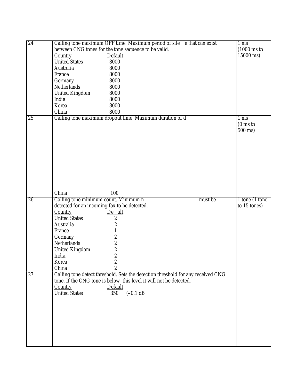
Parameter # Description Units
Á
Á
Á
Á
Á
Á
Á
Á
Á
БББББББББББББББББББББББББ
Á
Á
Á
Á
Á
Á
Á
Á
Á
Á
Á
Á
Á
Á
Á
Á
Á
Á
Á
Á
Á
Á
Á
Á
Á
Á
Á
Á
БББББББББББББББББББББББББ
Á
Á
Á
Á
Á
Á
Á
Á
Á
Á
Á
Á
Á
Á
Á
Á
Á
Á
Á
Á
Á
Á
Á
Á
Á
Á
Á
Á
Á
БББББББББББББББББББББББББ
Á
Á
Á
Á
Á
Á
Á
Á
Á
Á
Á
Á
Á
Á
Á
Á
Á
Á
Á
Á
Á
Á
Á
Á
Á
Á
Á
БББББББББББББББББББББББББ
Á
Á
Á
Á
Á
Á
Á
Á
Á
Á
Á
Á
Á
Á
Á
Á
Á
Á
24
ÁÁÁ
ÁÁÁ
ÁÁÁ
ÁÁÁ
ÁÁÁ
ÁÁÁ
ÁÁÁ
ÁÁÁ
ÁÁÁ
25
ÁÁÁ
ÁÁÁ
ÁÁÁ
ÁÁÁ
ÁÁÁ
ÁÁÁ
ÁÁÁ
ÁÁÁ
ÁÁÁ
ÁÁÁ
26
ÁÁÁ
ÁÁÁ
ÁÁÁ
ÁÁÁ
ÁÁÁ
ÁÁÁ
ÁÁÁ
ÁÁÁ
ÁÁÁ
27
ÁÁÁ
ÁÁÁ
ÁÁÁ
ÁÁÁ
ÁÁÁ
ÁÁÁ
ÁÁÁ
ÁÁÁ
ÁÁÁ
Calling tone maximum OFF time. Maximum period of silence that can exist
between CNG tones for the tone sequence to be valid.
ББББББББББББББББББББББББ
Country Default
ББББББББББББББББББББББББ
United States 8000
ББББББББББББББББББББББББ
Australia 8000
ББББББББББББББББББББББББ
France 8000
ББББББББББББББББББББББББ
Germany 8000
Netherlands 8000
ББББББББББББББББББББББББ
United Kingdom 8000
ББББББББББББББББББББББББ
India 8000
ББББББББББББББББББББББББ
Korea 8000
ББББББББББББББББББББББББ
China 8000
Calling tone maximum dropout time. Maximum duration of dropout which can
interrupt a CNG tone. If the dropout is less than this time, then the CNG tone will
ББББББББББББББББББББББББ
be processed as a single continuous tone.
ББББББББББББББББББББББББ
Country
ББББББББББББББББББББББББ
United States 100
ББББББББББББББББББББББББ
Australia 100
ББББББББББББББББББББББББ
France 100
Germany 100
ББББББББББББББББББББББББ
Netherlands 100
ББББББББББББББББББББББББ
United Kingdom 100
ББББББББББББББББББББББББ
India 100
ББББББББББББББББББББББББ
Korea 100
ББББББББББББББББББББББББ
China 100
Default
Calling tone minimum count. Minimum number of CNG tones that must be
detected for an incoming fax to be detected.
ББББББББББББББББББББББББ
Country
ББББББББББББББББББББББББ
United States 2
ББББББББББББББББББББББББ
Australia 2
ББББББББББББББББББББББББ
France 1
ББББББББББББББББББББББББ
Germany 2
Netherlands 2
ББББББББББББББББББББББББ
United Kingdom 2
ББББББББББББББББББББББББ
India 2
ББББББББББББББББББББББББ
Korea 2
ББББББББББББББББББББББББ
China 2
Default
Calling tone detect threshold. Sets the detection threshold for any received CNG
tone. If the CNG tone is below this level it will not be detected.
ББББББББББББББББББББББББ
Country Default
ББББББББББББББББББББББББ
United States 350 (–0.1 dBm)
ББББББББББББББББББББББББ
Australia 350 (–0.1 dBm)
ББББББББББББББББББББББББ
France 450 (–0.1 dBm)
ББББББББББББББББББББББББ
Germany 350 (–0.1 dBm)
Netherlands 350 (–0.1 dBm)
ББББББББББББББББББББББББ
United Kingdom 350 (–0.1 dBm)
ББББББББББББББББББББББББ
India 450 (–0.1 dBm)
ББББББББББББББББББББББББ
Korea 350 (–0.1 dBm)
ББББББББББББББББББББББББ
China 450 (–0.1 dBm)
1 ms
(1000 ms to
ÁÁÁÁ
15000 ms)
ÁÁÁÁ
ÁÁÁÁ
ÁÁÁÁ
ÁÁÁÁ
ÁÁÁÁ
ÁÁÁÁ
ÁÁÁÁ
ÁÁÁÁ
1 ms
(0 ms to
ÁÁÁÁ
500 ms)
ÁÁÁÁ
ÁÁÁÁ
ÁÁÁÁ
ÁÁÁÁ
ÁÁÁÁ
ÁÁÁÁ
ÁÁÁÁ
ÁÁÁÁ
ÁÁÁÁ
1 tone (1 tone
to 15 tones)
ÁÁÁÁ
ÁÁÁÁ
ÁÁÁÁ
ÁÁÁÁ
ÁÁÁÁ
ÁÁÁÁ
ÁÁÁÁ
ÁÁÁÁ
ÁÁÁÁ
10
(260 to 510)
ÁÁÁÁ
ÁÁÁÁ
ÁÁÁÁ
ÁÁÁÁ
ÁÁÁÁ
ÁÁÁÁ
ÁÁÁÁ
ÁÁÁÁ
ÁÁÁÁ
Problem Resolution
5-57
Page 97

Parameter # Description Units
Á
Á
Á
Á
Á
Á
Á
Á
Á
Á
Á
БББББББББББББББББББББББББ
Á
Á
Á
Á
Á
Á
Á
Á
Á
Á
Á
Á
Á
Á
Á
Á
Á
Á
Á
Á
Á
Á
Á
Á
Á
Á
Á
Á
Á
Á
Á
Á
БББББББББББББББББББББББББ
Á
Á
Á
Á
Á
Á
Á
Á
Á
Á
Á
Á
Á
Á
Á
Á
Á
Á
Á
Á
Á
Á
Á
Á
Á
Á
Á
Á
Á
Á
Á
БББББББББББББББББББББББББ
Á
Á
Á
Á
Á
Á
Á
Á
Á
Á
Á
Á
Á
Á
Á
Á
Á
Á
Á
Á
Á
Á
28
ÁÁÁ
ÁÁÁ
ÁÁÁ
ÁÁÁ
ÁÁÁ
ÁÁÁ
ÁÁÁ
ÁÁÁ
ÁÁÁ
ÁÁÁ
ÁÁÁ
29
ÁÁÁ
ÁÁÁ
ÁÁÁ
ÁÁÁ
ÁÁÁ
ÁÁÁ
ÁÁÁ
ÁÁÁ
ÁÁÁ
ÁÁÁ
ÁÁÁ
30
ÁÁÁ
ÁÁÁ
ÁÁÁ
ÁÁÁ
ÁÁÁ
ÁÁÁ
ÁÁÁ
ÁÁÁ
ÁÁÁ
ÁÁÁ
ÁÁÁ
Problem Resolution
5-58
Silence minimum time. An incoming fax will be detected if this period of silence is
detected. Silent detection is only intended to apply to downstream TADs. Silent
ББББББББББББББББББББББББ
detection will only start after an OGM has been detected and if downstream
ББББББББББББББББББББББББ
activity is detected.
ББББББББББББББББББББББББ
Country Default
ББББББББББББББББББББББББ
United States 3000
ББББББББББББББББББББББББ
Australia 3000
France 3000
ББББББББББББББББББББББББ
Germany 3000
ББББББББББББББББББББББББ
Netherlands 3000
ББББББББББББББББББББББББ
United Kingdom 3000
ББББББББББББББББББББББББ
India 3000
ББББББББББББББББББББББББ
Korea 3000
China 3000
ББББББББББББББББББББББББ
FAX TAM interface enable. If TRUE then the user will be able to select FAX/TAM
as a receive configuration. If FALSE the FAX/TAM selections will not be seen by
ББББББББББББББББББББББББ
the user when selecting a receive mode. Intended for countries which do not allow
ББББББББББББББББББББББББ
FAX/TAM support.
ББББББББББББББББББББББББ
Country
United States 0
ББББББББББББББББББББББББ
Australia 0
ББББББББББББББББББББББББ
France 0
ББББББББББББББББББББББББ
Germany 0
ББББББББББББББББББББББББ
Netherlands 0
ББББББББББББББББББББББББ
United Kingdom 0
ББББББББББББББББББББББББ
India 0
Korea 0
ББББББББББББББББББББББББ
China 0
ББББББББББББББББББББББББ
Calling tone auto stop enable. If TRUE, HP OfficeJet Series 300 will stop
ББББББББББББББББББББББББ
transmitting the CNG signal as soon as 750 ms of an incoming CED signal has
ББББББББББББББББББББББББ
been detected. If this value is FALSE, it will transmit the CNG signal until T30
ББББББББББББББББББББББББ
frames are detected.
Country
ББББББББББББББББББББББББ
United States 0
ББББББББББББББББББББББББ
Australia 0
ББББББББББББББББББББББББ
France 1
ББББББББББББББББББББББББ
Germany 0
ББББББББББББББББББББББББ
Netherlands 0
United Kingdom 0
ББББББББББББББББББББББББ
India 0
ББББББББББББББББББББББББ
Korea 0
ББББББББББББББББББББББББ
China 0
Default
Default
1 ms
(1000 ms to
ÁÁÁÁ
15000 ms)
ÁÁÁÁ
ÁÁÁÁ
ÁÁÁÁ
ÁÁÁÁ
ÁÁÁÁ
ÁÁÁÁ
ÁÁÁÁ
ÁÁÁÁ
ÁÁÁÁ
ÁÁÁÁ
0 = FALSE
1 = TRUE
ÁÁÁÁ
ÁÁÁÁ
ÁÁÁÁ
ÁÁÁÁ
ÁÁÁÁ
ÁÁÁÁ
ÁÁÁÁ
ÁÁÁÁ
ÁÁÁÁ
ÁÁÁÁ
ÁÁÁÁ
0 = FALSE
ÁÁÁÁ
1 = TRUE
ÁÁÁÁ
ÁÁÁÁ
ÁÁÁÁ
ÁÁÁÁ
ÁÁÁÁ
ÁÁÁÁ
ÁÁÁÁ
ÁÁÁÁ
ÁÁÁÁ
ÁÁÁÁ
Page 98

Connection Establishment
Á
Á
Á
Á
Á
Á
Á
Á
Á
БББББББББББББББББББББББББ
Á
Á
Á
Á
Á
Á
Á
Á
Á
Á
Á
Á
Á
Á
Á
Á
Á
Á
Á
Á
Á
Á
Á
Á
Á
Á
Á
Á
БББББББББББББББББББББББББ
Á
Á
Á
Á
Á
Á
Á
Á
Á
Á
Á
Á
Á
Á
Á
Á
Á
Á
Á
Á
Á
БББББББББББББББББББББББББ
Á
Á
Á
Á
Á
Á
Á
Á
Á
Á
Á
Á
Á
БББББББББББББББББББББББББ
Á
Á
Á
Á
Á
Á
Á
Á
Á
Á
Á
Á
Á
Á
Á
Á
Á
Á
Á
Á
Á
Á
Parameter # Description Units
31
ÁÁÁ
ÁÁÁ
ÁÁÁ
ÁÁÁ
ÁÁÁ
ÁÁÁ
ÁÁÁ
ÁÁÁ
ÁÁÁ
Line seizure delay timer. Specifies the minimum time between the completion of
ББББББББББББББББББББББББ
an outgoing or incoming call and the automatic dialing of the next outgoing call.
ББББББББББББББББББББББББ
Country Default
United States 5000
ББББББББББББББББББББББББ
Australia 5000
ББББББББББББББББББББББББ
France 6500
ББББББББББББББББББББББББ
Germany 7000
ББББББББББББББББББББББББ
Netherlands 7000
ББББББББББББББББББББББББ
United Kingdom 3500
India 5000
ББББББББББББББББББББББББ
Korea 5000
ББББББББББББББББББББББББ
China 5000
32
ÁÁÁ
ÁÁÁ
ÁÁÁ
ÁÁÁ
ÁÁÁ
ÁÁÁ
ÁÁÁ
ÁÁÁ
ÁÁÁ
ÁÁÁ
33
ÁÁÁ
34
ÁÁÁ
ÁÁÁ
ÁÁÁ
ÁÁÁ
ÁÁÁ
ÁÁÁ
ÁÁÁ
ÁÁÁ
ÁÁÁ
ÁÁÁ
ÁÁÁ
Pre OFF hook shunt. Defines the time the LIU shunt will be active. The shunt is
ББББББББББББББББББББББББ
activated just prior to when HP OfficeJet Series 300 goes OFF hook. Not supported
ББББББББББББББББББББББББ
by all LIUs.
Country
ББББББББББББББББББББББББ
United States 0
ББББББББББББББББББББББББ
Australia 325
ББББББББББББББББББББББББ
France 0
ББББББББББББББББББББББББ
Germany 0
ББББББББББББББББББББББББ
Netherlands 0
United Kingdom 0
ББББББББББББББББББББББББ
India 0
ББББББББББББББББББББББББ
Korea 0
ББББББББББББББББББББББББ
China 0
Default
(Reserved)
ББББББББББББББББББББББББ
Modem loop current failure test enable. Controls is a modem loop current test is
performed after HP OfficeJet Series 300 has dialed a number or after it has
ББББББББББББББББББББББББ
answered an incoming call. If TRUE it will continuously test for the absence of
ББББББББББББББББББББББББ
loop current. If no loop current is detected the fax session will be aborted.
ББББББББББББББББББББББББ
Country
ББББББББББББББББББББББББ
United States 0
ББББББББББББББББББББББББ
Australia 0
France 0
ББББББББББББББББББББББББ
Germany 0
ББББББББББББББББББББББББ
Netherlands 0
ББББББББББББББББББББББББ
United Kingdom 0
ББББББББББББББББББББББББ
India 0
ББББББББББББББББББББББББ
Korea 0
China 0
ББББББББББББББББББББББББ
Default
1 ms (0 ms to
ÁÁÁÁ
15000 ms)
ÁÁÁÁ
ÁÁÁÁ
ÁÁÁÁ
ÁÁÁÁ
ÁÁÁÁ
ÁÁÁÁ
ÁÁÁÁ
ÁÁÁÁ
1 ms (0 ms to
ÁÁÁÁ
1000 ms)
ÁÁÁÁ
ÁÁÁÁ
ÁÁÁÁ
ÁÁÁÁ
ÁÁÁÁ
ÁÁÁÁ
ÁÁÁÁ
ÁÁÁÁ
ÁÁÁÁ
ÁÁÁÁ
0 = FALSE
1 = TRUE
ÁÁÁÁ
ÁÁÁÁ
ÁÁÁÁ
ÁÁÁÁ
ÁÁÁÁ
ÁÁÁÁ
ÁÁÁÁ
ÁÁÁÁ
ÁÁÁÁ
ÁÁÁÁ
ÁÁÁÁ
Problem Resolution
5-59
Page 99

Parameter # Description Units
Á
Á
Á
Á
Á
Á
Á
Á
Á
Á
Á
БББББББББББББББББББББББББ
Á
Á
Á
Á
Á
Á
Á
Á
Á
Á
Á
Á
Á
Á
Á
Á
Á
Á
Á
Á
Á
Á
Á
Á
Á
Á
Á
Á
Á
Á
Á
Á
Á
БББББББББББББББББББББББББ
Á
Á
Á
Á
Á
Á
Á
Á
Á
Á
Á
Á
Á
Á
Á
Á
Á
Á
Á
Á
Á
Á
Á
Á
Á
Á
Á
Á
Á
Á
Á
Á
Á
БББББББББББББББББББББББББ
Á
Á
Á
Á
Á
Á
Á
Á
Á
Á
Á
Á
Á
Á
Á
Á
Á
Á
Á
Á
Á
Á
35
ÁÁÁ
ÁÁÁ
ÁÁÁ
ÁÁÁ
ÁÁÁ
ÁÁÁ
ÁÁÁ
ÁÁÁ
ÁÁÁ
ÁÁÁ
ÁÁÁ
Modem loop current test enable. Controls if a modem loop current test is
performed after HP OfficeJet Series 300 has connected to the external line and
ББББББББББББББББББББББББ
before dialing is started.. If TRUE, HP OfficeJet Series 300 will test for the
ББББББББББББББББББББББББ
presence of loop current after going OFF hook prior to dialing. If loop current is
ББББББББББББББББББББББББ
not detected, the fax session is aborted.
ББББББББББББББББББББББББ
Country Default
United States 0
ББББББББББББББББББББББББ
Australia 1
ББББББББББББББББББББББББ
France 1
ББББББББББББББББББББББББ
Germany 1
ББББББББББББББББББББББББ
Netherlands 1
ББББББББББББББББББББББББ
United Kingdom 1
India 0
ББББББББББББББББББББББББ
Korea 0
ББББББББББББББББББББББББ
China 0
36
ÁÁÁ
ÁÁÁ
ÁÁÁ
ÁÁÁ
ÁÁÁ
ÁÁÁ
ÁÁÁ
ÁÁÁ
ÁÁÁ
ÁÁÁ
ÁÁÁ
37
ÁÁÁ
ÁÁÁ
ÁÁÁ
ÁÁÁ
ÁÁÁ
ÁÁÁ
ÁÁÁ
ÁÁÁ
ÁÁÁ
ÁÁÁ
ÁÁÁ
Problem Resolution
5-60
Modem loop current detection time minimum. Minimum time that continuous
ББББББББББББББББББББББББ
modem loop current must be present when the machine fist connects and a loop
ББББББББББББББББББББББББ
current test is performed. Also, this is the minimum time that loop current must be
ББББББББББББББББББББББББ
absent once dialing has completed, when performing the loop current failure test.
Country
ББББББББББББББББББББББББ
United States 0
ББББББББББББББББББББББББ
Australia 200
ББББББББББББББББББББББББ
France 250
ББББББББББББББББББББББББ
Germany 200
ББББББББББББББББББББББББ
Netherlands 200
United Kingdom 200
ББББББББББББББББББББББББ
India 0
ББББББББББББББББББББББББ
Korea 0
ББББББББББББББББББББББББ
China 0
Default
Modem loop current detection delay. The delay that occurs before starting the loop
ББББББББББББББББББББББББ
current failure test. Allows time for the network to settle after dialing and prevents
”open switch interrupts” from falsely being interpreted as problems with the
ББББББББББББББББББББББББ
connection.
ББББББББББББББББББББББББ
Country
ББББББББББББББББББББББББ
United States 0
ББББББББББББББББББББББББ
Australia 10000
ББББББББББББББББББББББББ
France 10000
Germany 10000
ББББББББББББББББББББББББ
Netherlands 10000
ББББББББББББББББББББББББ
United Kingdom 10000
ББББББББББББББББББББББББ
India 0
ББББББББББББББББББББББББ
Korea 0
ББББББББББББББББББББББББ
China 0
Default
0 = FALSE
1 = TRUE
ÁÁÁÁ
ÁÁÁÁ
ÁÁÁÁ
ÁÁÁÁ
ÁÁÁÁ
ÁÁÁÁ
ÁÁÁÁ
ÁÁÁÁ
ÁÁÁÁ
ÁÁÁÁ
ÁÁÁÁ
1 ms
ÁÁÁÁ
(0 ms to
ÁÁÁÁ
15000 ms)
ÁÁÁÁ
ÁÁÁÁ
ÁÁÁÁ
ÁÁÁÁ
ÁÁÁÁ
ÁÁÁÁ
ÁÁÁÁ
ÁÁÁÁ
ÁÁÁÁ
1 ms
ÁÁÁÁ
(0 ms to
15000 ms)
ÁÁÁÁ
ÁÁÁÁ
ÁÁÁÁ
ÁÁÁÁ
ÁÁÁÁ
ÁÁÁÁ
ÁÁÁÁ
ÁÁÁÁ
ÁÁÁÁ
ÁÁÁÁ
Page 100

Parameter # Description Units
Á
Á
Á
Á
Á
Á
Á
Á
Á
БББББББББББББББББББББББББ
Á
Á
Á
Á
Á
Á
Á
Á
Á
Á
Á
Á
Á
Á
Á
Á
Á
Á
Á
Á
Á
Á
Á
Á
Á
Á
Á
Á
Á
БББББББББББББББББББББББББ
Á
Á
Á
Á
Á
Á
Á
Á
Á
Á
Á
Á
Á
Á
Á
Á
Á
Á
Á
Á
Á
Á
Á
Á
Á
Á
Á
Á
Á
Á
Á
Á
БББББББББББББББББББББББББ
Á
Á
Á
Á
Á
Á
Á
Á
Á
Á
Á
Á
Á
Á
Á
Á
Á
Á
Á
Á
38
ÁÁÁ
ÁÁÁ
ÁÁÁ
ÁÁÁ
ÁÁÁ
ÁÁÁ
ÁÁÁ
ÁÁÁ
ÁÁÁ
39
ÁÁÁ
ÁÁÁ
ÁÁÁ
ÁÁÁ
ÁÁÁ
ÁÁÁ
ÁÁÁ
ÁÁÁ
ÁÁÁ
ÁÁÁ
ÁÁÁ
40
ÁÁÁ
ÁÁÁ
ÁÁÁ
ÁÁÁ
ÁÁÁ
ÁÁÁ
ÁÁÁ
ÁÁÁ
ÁÁÁ
ÁÁÁ
Modem loop current evaluation time. Maximum time the machine will wait for
loop current before dialing when performing a loop current test.
ББББББББББББББББББББББББ
Country Default
ББББББББББББББББББББББББ
United States 0
ББББББББББББББББББББББББ
Australia 4000
ББББББББББББББББББББББББ
France 4000
ББББББББББББББББББББББББ
Germany 4000
Netherlands 4000
ББББББББББББББББББББББББ
United Kingdom 4000
ББББББББББББББББББББББББ
India 0
ББББББББББББББББББББББББ
Korea 0
ББББББББББББББББББББББББ
China 0
Telset loop current test enable. Controls whether a telset loop current test is
performed before HP OfficeJet Series 300 is connected to the external line. The
ББББББББББББББББББББББББ
presence of loop current would indicate that a downstream telephone is active. If
ББББББББББББББББББББББББ
TRUE, the machine will check for telset loop current.
ББББББББББББББББББББББББ
Country Default
ББББББББББББББББББББББББ
United States 1
ББББББББББББББББББББББББ
Australia 1
France 1
ББББББББББББББББББББББББ
Germany 1
ББББББББББББББББББББББББ
Netherlands 1
ББББББББББББББББББББББББ
United Kingdom 1
ББББББББББББББББББББББББ
India 1
ББББББББББББББББББББББББ
Korea 1
ББББББББББББББББББББББББ
China 1
Telset loop current detection time minimum. Minimum time that continuous telset
loop current must be absent to be evaluated as absent. Once absent the line is
ББББББББББББББББББББББББ
considered available.
ББББББББББББББББББББББББ
Country
ББББББББББББББББББББББББ
United States 1000
ББББББББББББББББББББББББ
Australia 1000
France 5000
ББББББББББББББББББББББББ
Germany 1000
ББББББББББББББББББББББББ
Netherlands 1000
ББББББББББББББББББББББББ
United Kingdom 1000
ББББББББББББББББББББББББ
India 1000
ББББББББББББББББББББББББ
Korea 1000
China 1000
ББББББББББББББББББББББББ
Default
1 ms
(0 ms to
ÁÁÁÁ
15000 ms)
ÁÁÁÁ
ÁÁÁÁ
ÁÁÁÁ
ÁÁÁÁ
ÁÁÁÁ
ÁÁÁÁ
ÁÁÁÁ
ÁÁÁÁ
0 = FALSE
1 = TRUE
ÁÁÁÁ
ÁÁÁÁ
ÁÁÁÁ
ÁÁÁÁ
ÁÁÁÁ
ÁÁÁÁ
ÁÁÁÁ
ÁÁÁÁ
ÁÁÁÁ
ÁÁÁÁ
ÁÁÁÁ
1 ms
(50 ms to
ÁÁÁÁ
15000 ms)
ÁÁÁÁ
ÁÁÁÁ
ÁÁÁÁ
ÁÁÁÁ
ÁÁÁÁ
ÁÁÁÁ
ÁÁÁÁ
ÁÁÁÁ
ÁÁÁÁ
Problem Resolution
5-61
 Loading...